JP5017510B2 - Game machine - Google Patents
Game machine Download PDFInfo
- Publication number
- JP5017510B2 JP5017510B2 JP2009192911A JP2009192911A JP5017510B2 JP 5017510 B2 JP5017510 B2 JP 5017510B2 JP 2009192911 A JP2009192911 A JP 2009192911A JP 2009192911 A JP2009192911 A JP 2009192911A JP 5017510 B2 JP5017510 B2 JP 5017510B2
- Authority
- JP
- Japan
- Prior art keywords
- reach
- control board
- image
- random number
- value
- Prior art date
- Legal status (The legal status is an assumption and is not a legal conclusion. Google has not performed a legal analysis and makes no representation as to the accuracy of the status listed.)
- Expired - Lifetime
Links
Images


Description
本発明は遊技機に関し、詳しくは遊技機のリーチ画像の変動表示制御に係る。 The present invention relates to a gaming machine, and more particularly to variable display control of a reach image of a gaming machine.
遊技機、例えば、パチンコ機やアレンジボール式パチンコ機等の弾球遊技機には、判定条件の成立、例えば始動入賞口への入賞があることに起因して、特別遊技状態とするか否かの当否判定を行い、複数の図柄を可変表示装置に変動表示した後に順次停止表示してその判定結果を表示するものがある。この判定結果の表示(大当り図柄とも特定表示結果とも呼ばれる)、例えば3個の図柄の組合せで表示、例えば777のように3図柄が揃えば大当り表示とし特別遊技状態を発生するようになっており、一方、そうでなければ外れの表示とするのが普通である。この場合、当否判定が行われると、例えばスクロール等によって変動表示し、3個の図柄を例えば左、右、中の順に停止表示してすべてが停止表示された時点で当り外れが確定される。左と右の図柄が異なれば、例えば左の図柄が7で右の図柄が8で停止されたとすると、その時点で外れであることが判明する。左と右の図柄が同じなら、例えば左、右ともに7なら、最後に停止表示される中の図柄が7になるか否かで当りか外れかが決まるわけで、これをリーチ表示と呼んでいる(単にリーチともいう)。 Whether or not a game machine, for example, a ball or ball game machine such as a pachinko machine or an arrangement ball type pachinko machine, is put into a special game state due to the establishment of a judgment condition, for example, a prize at a start winning opening In other cases, the determination of whether or not is performed, a plurality of symbols are variably displayed on the variable display device, and then sequentially stopped and displayed to display the determination result. This judgment result display (also called a jackpot symbol or a specific display result), for example, a combination of three symbols, such as 777, if three symbols are aligned, a bonus game is displayed and a special gaming state is generated. On the other hand, otherwise, it is normal to display a detachment. In this case, when the determination is made, for example, the display is variably displayed by scrolling or the like, and the three symbols are stopped and displayed in the order of, for example, left, right, and the middle, and when all are stopped and displayed, the hit / miss is determined. If the left and right symbols are different, for example, if the left symbol is 7 and the right symbol is stopped at 8, it is determined that the symbol is out of place at that time. If the left and right symbols are the same, for example, if both the left and right are 7, the final symbol that is displayed in a stop state will be determined by whether or not it will be 7, so this is called reach display. Yes (also simply called reach).
このリーチ表示においては、例えば、最後に停止させられる図柄の変動速度を変化させたり、背景の画像を変化させたり、あるいは人物等が登場して何らかの動作をする等、さまざまなリーチアクションと呼ばれる表示がなされ、それらリーチアクション毎に信頼度が異なるように設定するのが普通である。このため、遊技者は、リーチの信頼度が高いリーチアクションであると期待を大きくし、そうでない場合には大して期待しない等、リーチアクションにより一喜一憂させられていた。 In this reach display, for example, various reach actions such as changing the speed of change of the symbol that is stopped at the end, changing the background image, or performing some action such as the appearance of a person, etc. Normally, the reliability is set differently for each reach action. For this reason, the player has been amazed by the reach action, such as increasing the expectation that the reach action is highly reachable and not expecting it otherwise.
このリーチの信頼度は、リーチとなってから当りが表示される確率であり、大当り確率とリーチ判定確率の逆数との積で算出される。大当り確率とは大当りとなる確率であり、リーチ判定確率とはリーチとする確率である。例えば、大当り確率が1/300でリーチ判定確率が1/30の場合、リーチの大当りに対する信頼度は0.1(10%)であり、大当り確率が1/300でリーチ判定確率が1/6の場合、リーチの信頼度は0.02(2%)である。ここで、リーチ判定確率が1/30ということは、確率論からいえば、前述の当否判定が連続して30回行われたとすると、そのうちの1回はリーチ変動表示となり、それ以外はすべて非リーチ変動表示になる設定であるということである。尚、大当り確率が1/300でリーチ判定確率が1/300の場合、リーチ表示すると必ず大当りとなり、リーチの信頼度は100%となる。 The reach reliability is the probability that a hit is displayed after reaching reach, and is calculated by the product of the big hit probability and the reciprocal of the reach determination probability. The jackpot probability is the probability of a big hit, and the reach determination probability is the probability of reaching. For example, when the jackpot probability is 1/300 and the reach determination probability is 1/30, the reliability of the reach jackpot is 0.1 (10%), the jackpot probability is 1/300 and the reach determination probability is 1/6. In this case, the reach reliability is 0.02 (2%). Here, if the reach determination probability is 1/30, according to probability theory, if the above-described success / failure determination is performed 30 times in succession, one of them is displayed as reach fluctuation, and all other cases are not displayed. This means that the setting is a reach variation display. When the big hit probability is 1/300 and the reach determination probability is 1/300, the reach is always a big hit when the reach is displayed, and the reach reliability is 100%.
ところが、従来では、主制御基板によってリーチ変動を実行するか否かを決定するので、主制御基板の負担が重くなるとともに、リーチ変動を連続で発生させたり、変動回数に従って発生させたりする等、自由にリーチ画像を表示制御する自由度に制限が生じるという問題がある。また、変動時間とリーチ画像の表示との関係が明確ではなく、リーチ表示の趣向性に限界が生じていた。さらに、リーチ判定確率が大きいということはリーチ信頼度が低く、リーチされた場合に大当りとなる確率が低くなる反面、リーチ回数が集中し面白さが高まる。一方、リーチ判定確率が低いということはリーチの信頼度が高く、リーチ表示された場合に大当りとなる確率が高くなる反面、リーチ表示回数が少なくなり図柄の変動停止画面が単調となり面白さに欠けることを意味する。従って、従来の手法ではリーチの集中とリーチの信頼度の向上との相関関係を改善することは困難であった。即ち、遊技者にしてみれば、リーチが集中すれば大当りが近いと感じ期待感が高まるのが普通であるが、実際にはリーチが集中したとしても却ってリーチの信頼度が低くなるものであり、遊技者がリーチへの信頼を失い、遊技の趣向が失われるおそれがある。 However, in the past, since it is determined whether or not the reach variation is executed by the main control board, the burden on the main control board becomes heavy, and the reach variation is continuously generated or generated according to the number of changes. There is a problem that the degree of freedom in freely controlling the display of reach images is limited. In addition, the relationship between the variation time and the reach image display is not clear, and there is a limit to the preference of reach display. Furthermore, a high reach determination probability means low reach reliability, and the probability of winning a big hit when reaching is low, but the reach frequency is concentrated and the fun is increased. On the other hand, if the reach determination probability is low, the reach reliability is high and the probability of winning a big hit when reach display is high, but the number of reach display is reduced and the pattern change stop screen is monotonous and lacks in interest. Means that. Therefore, it has been difficult to improve the correlation between the concentration of reach and the increase in reach reliability with the conventional method. In other words, for players, if the reach is concentrated, it is normal to feel that the big hit is near and the expectation will increase, but even if the reach is concentrated, the reliability of the reach will be lowered on the contrary. The player may lose confidence in the reach and lose the game preferences.
そこで、本発明は、主制御基板の制御負担を軽減すること、リーチ変動を連続で発生させたり、変動回数に従って発生させたりする等、自由にリーチ画像を表示制御できること、リーチ表示の趣向性を高まること、リーチが集中する場合はリーチの信頼度を高め、リーチにおける興趣を盛り上げることを可能とする遊技機を提供することを目的とする。 Therefore, the present invention can reduce the control burden on the main control board, can generate reach fluctuations continuously, or can generate reach images freely according to the number of fluctuations. It is an object of the present invention to provide a gaming machine that can increase the reliability of reach when the reach is concentrated, and increase the interest in reach.
前記課題を解決するため請求項1に記載の遊技機は、遊技球の入球に起因して遊技者に有利なゲームを実行するか否かを決定する当否乱数を有する条件成立判定手段を備えた遊技制御基板と、
前記条件成立判定手段により抽出された前記当否乱数の値が所定値である場合には遊技者に有利なゲームが実行される旨の有利報知画像、条件が成立しない場合には有利なゲームが実行されない旨の不利報知画像を表示する報知画像表示手段を備えた画像制御基板と、
前記遊技制御基板に、
前記報知画像表示手段により表示される画像の変動時間を前記入球に起因して複数の変動時間の中から決定する変動時間決定手段と、
該変動時間決定手段により決定された変動時間を示すデータ及び前記条件成立判定手段により抽出された前記当否乱数の値が所定値であるか否かを示す当否データを前記画像制御基板に送信するデータ送信手段と、
を備え、前記画像制御基板の報知画像表示手段は、受信した前記変動時間を示すデータに従って前記有利報知画像又は前記不利報知画像を変動表示する遊技機であって、
前記画像制御基板に、
受信した前記当否データに基づき遊技者に有利なゲームを実行しないと判定したとき、 前記有利報知画像が成立する前提条件となるリーチ画像を表示するか否かをリーチ乱数の抽出により決定するリーチ決定手段と、
該リーチ決定手段によりリーチ画像を表示すると決定された場合には、該リーチ画像を含む前記不利報知画像を決定し、該不利報知画像の画像制御データを生成して該決定された不利報知画像を受信した前記変動時間に従って変動表示するリーチ画像表示手段と、
を備え、
前記画像制御基板と前記遊技制御基板との送信は、前記遊技制御基板からのみ送信することができる一方向通信であり、
前記リーチ乱数は、前記受信した変動時間を示すデータが長い変動時間を示している場合、変動時間が短い場合よりリーチ発生確率が高く、
前記画像制御基板の前記リーチ画像表示手段が前記リーチ画像を変動表示するとき、前記リーチ画像に伴う制御を前記遊技制御基板は行わない、
ことを特徴とする遊技機である。
In order to solve the above-mentioned problem, the gaming machine according to
An advantageous notification image that a game advantageous to the player is executed when the value of the success / failure random number extracted by the condition establishment determining means is a predetermined value, and an advantageous game is executed when the condition is not established An image control board provided with a notification image display means for displaying a disadvantage notification image indicating that
In the game control board,
Fluctuation time determination means for determining a fluctuation time of an image displayed by the notification image display means from a plurality of fluctuation times due to the entry,
Data indicating the variation time determined by the variation time determination means and data for transmitting to the image control board the success / failure data indicating whether or not the value of the success / failure random number extracted by the condition satisfaction determination means is a predetermined value. A transmission means;
The notification image display means of the image control board is a gaming machine that variably displays the advantage notification image or the disadvantage notification image according to the received data indicating the variation time,
On the image control board,
Reach determination for determining whether or not to display a reach image as a precondition for establishing the advantage notification image when it is determined not to execute a game advantageous to the player based on the received success / failure data Means,
When the reach determination means determines to display the reach image, the disadvantage notification image including the reach image is determined, image control data of the disadvantage notification image is generated, and the determined disadvantage notification image is displayed. Reach image display means for variably displaying according to the received variation time;
Bei to give a,
Transmission between the image control board and the game control board is a one-way communication that can be transmitted only from the game control board,
The reach random number has a higher reach probability than the case where the variation time is short when the received data indicating the variation time indicates a long variation time,
When the reach image display means of the image control board displays the reach image variably, the game control board does not perform the control associated with the reach image.
It is a gaming machine characterized by this.
前記構成を有する請求項1に記載の遊技機は、前記画像制御基板でリーチ変動を実行するか否かをリーチ乱数の抽出により決定するので、遊技制御基板の負担が軽減されるとともに、リーチ変動を連続で発生させたり、変動回数に従って発生させたりする等、自由にリーチ画像を表示制御することができる。また、変動時間に従ってリーチ画像を表示させているので、リーチ表示の趣向性を高まることができる。
遊技制御基板は、抽選の当否結果を示す当否データを送信する。受信した当否データに基づき遊技者に有利なゲームを実行しないと判定したとき、 画像制御基板がリーチ画像を表示するか否かを決定する。リーチ画像を含む前記不利報知画像を画像制御基板が決定する。
これにより、遊技制御基板は、当否結果が外れ時にリーチ表示を行うか否か決定する必要なく、リーチ画像を含む不利報知画像を決定する必要なく、処理の負担は軽減化される。
一方、リーチ画像を表示するか否かを画像制御基板が決定し、リーチ画像を含む不利報知画像を画像制御基板が決定するので、リーチ変動を連続で発生させたり、変動回数に従って発生させたりする等、自由にリーチ画像を画像制御基板が表示制御することができる。
また、請求項1に記載の遊技機は、受信した変動時間が長ければリーチ発生確率を高くするので、長い変動時間であっても遊技者は画面に飽きなく、大当たりに対する期待を抱かせることができる。
更に、前記画像制御基板の前記リーチ画像表示手段が前記リーチ画像を変動表示するとき、前記リーチ画像に伴う制御を前記遊技制御基板は行わないので、遊技制御基板の処理の負担を極めて軽減化することができる。
The gaming machine according to
The game control board transmits success / failure data indicating the success / failure result of lottery. When it is determined that the game advantageous to the player is not executed based on the received correct / incorrect data, the image control board determines whether or not to display the reach image. The image control board determines the disadvantage notification image including the reach image.
Thereby, the game control board does not need to determine whether or not to perform reach display when the result is unacceptable, and does not need to determine the disadvantage notification image including the reach image, thereby reducing the processing load.
On the other hand, since the image control board determines whether or not to display the reach image, and the image control board determines the disadvantage notification image including the reach image, the reach variation is generated continuously or according to the number of times of the change. The image control board can display and control the reach image freely.
In addition, since the gaming machine according to
Further, when the reach image display means of the image control board displays the reach image in a variable manner, the game control board does not perform the control associated with the reach image, thereby greatly reducing the processing load on the game control board. be able to.
ここでいう「有利なゲーム」とは、有利報知画像を表示して大入賞口を開放するゲームは勿論、有利報知画像を表示して特定入賞口(特定入球口)を開放するゲームを含み、特定入賞口内の特定領域を通過することを条件に大入賞口を開放するゲームを付加しても良い。「遊技球の入球に起因して遊技者に有利なゲームを実行するか否かを決定する条件成立判定手段」は、例えば、遊技盤面上に発射された遊技球が特定の入球口に入球又は特定の通過口を通過するタイミングに起因して抽出される乱数値に従って遊技者に有利なゲーム内容とするか否かを決定するものである。特定の入球口に入球又は特定の通過口を通過するタイミングに起因して抽出される乱数の値により直接的に遊技者に有利な状態とすることは当然に含まれる他、特定の入球口に入球又は特定の通過口を通過するタイミングに起因して抽出される乱数の値により所定の入賞口(入球口)を開放し、この開放した特定入賞口内の特定領域を遊技球が通過すると遊技者に有利な状態とする所謂第3種遊技機(権利物)、アレンジボール遊技機、その他、第1種パチンコ機ないし第3種パチンコ機を適宜組み合わせて複合化された遊技機等、遊技機が有する間接的に遊技者に有利な状態とするゲーム内容も含む。尚、入球に伴い賞球としての遊技球を払い出す構成としても良いし(この場合、「入賞口」と呼ばれることが多い)、払い出さない構成としても良い。
The term “advantageous game” as used herein includes not only a game that displays an advantageous notification image and opens a special winning opening, but also a game that displays an advantageous notification image and opens a specific winning opening (specific entry gate). A game may be added that opens the grand prize opening on condition that the specific area in the specific winning opening is passed. “Condition establishment determination means for determining whether or not to execute a game advantageous to the player due to the entry of a game ball” is, for example, a game ball launched on a game board surface at a specific entrance Whether or not the game content is advantageous to the player is determined according to the random number value extracted due to the timing of entering the ball or passing through a specific passage. Naturally, it is naturally included in a state that is advantageous to the player by the value of a random number extracted due to the timing of entering or passing through a specific entrance. A predetermined winning entrance (entrance entrance) is opened by a random value extracted due to the timing of entering the ball entrance or passing through a specific passage entrance, and a specific area in the opened specific winning entrance is a game ball. So-called
「報知画像表示手段」とは、例えば、遊技者に有利なゲーム内容とするか否かを決定する毎に画面上の画像を変動表示した後、遊技者に有利なゲーム内容であるか否かを示す有利報知画像で静止表示するよう制御するものであれば良く、遊技者に有利なゲーム内容であることを示す画像は、例えば「777」のように3桁同一の記号を表示する画像、格闘技で主役(主人公)が優勝する画像、レースで主役が一番になる画像や、球技で主役が優勝する画像又はゴールする画像や、冒険物語で主役が宝物を発見する画像や、主役又は主役に関係する人々が利益を受ける等してハッピーな状態を示す画像が考えられる。また、「不利報知画像」としては、例えば「769」のように3桁非同一の記号を表示する画像、主人公が不幸な状態を示す画像等が含まれる。「報知画像表示手段」は、CRT及び液晶表示体の画面は言うに及ばず、ドットマトリクス表示体及び7セグメントLED等の前記画像を表示させることができる装置の表示部を含む。 “Notification image display means” means, for example, whether or not the game content is advantageous to the player after the image on the screen is variably displayed every time it is determined whether or not the game content is advantageous to the player. As long as it is controlled so as to be displayed statically with an advantageous notification image indicating, an image indicating that the game content is advantageous to the player is, for example, an image displaying the same three-digit symbol such as “777”, Images where the leading role (hero) wins in martial arts, images where the leading role wins the race, images where the leading role wins or finishes in ball games, images where the leading role finds a treasure in an adventure story, or the leading role or leading role An image showing a happy state can be considered, for example, by benefiting people related to. The “disadvantage notification image” includes, for example, an image that displays a three-digit non-identical symbol such as “769”, an image that indicates that the main character is unhappy, and the like. The “notification image display means” includes a display unit of a device capable of displaying the image, such as a dot matrix display and a 7-segment LED, as well as a screen of a CRT and a liquid crystal display.
「画像」とは、画面上に表示されるものであって、特別図柄、背景、キャラクタの個々を要素とするものでも良いし、それらの組合せでも良い。例えば、数字、文字、人物や動物等を示した図柄及び特定形状の特定色等も含む。図柄の形状が変化しなくとも良いし、変化させるものでも良い。例えば、同一でも拡大縮小いずれでも良い。 The “image” is displayed on the screen, and may be a special symbol, background, or character, or a combination thereof. For example, it includes numbers, letters, symbols and figures indicating people and animals, and specific colors of specific shapes. The shape of the pattern does not need to change or may change. For example, they may be the same or enlarged / reduced.
請求項2に記載の遊技機は、請求項1に記載の遊技機において、前記画像制御手段の前記リーチ決定手段は、当選値の数を相違させた確率の相違するリーチ乱数を2種類以上有し、抽選された乱数値が前記当選値と一致すれば前記リーチ画像を表示することを決定し、該乱数の確率の高い方により所定回数リーチ画像が表示された後、該乱数の確率の低い方を用いることを特徴とする遊技機である。
これにより、意図的にリーチ決定確率を変えることができる。つまりリーチ集中後は当り易い遊技機となり、リーチの頻発を遊技者が信用しないという面が解消ないし緩和できるという効果がある。
更に、所定回数はランダムなので、リーチの集中度が高まる期間をランダムに変化させることができる。
The gaming machine according to
Thereby, the reach determination probability can be changed intentionally. In other words, the game machine is easy to hit after concentration of reach, and the effect that the player does not trust the frequent occurrence of the reach can be eliminated or alleviated.
Furthermore, since the predetermined number of times is random, the period during which the concentration of reach is increased can be changed randomly.
以下に、本発明の好適な実施形態を図面に基づいて説明する。尚、本発明の実施の形態は、下記の実施形態に何ら限定されるものではなく、本発明の技術的範囲に属する限り種々の形態を採り得ることはいうまでもない。 Preferred embodiments of the present invention will be described below with reference to the drawings. Note that the embodiment of the present invention is not limited to the following embodiment, and it goes without saying that various forms can be adopted as long as it belongs to the technical scope of the present invention.
図1に示すように、本実施形態のパチンコ機10は、大きくは長方形の外枠11と前面枠12とからなり、外枠11の左隣に公知のプリペイドカードユニット13が設けられている。前面枠12は、左端上下のヒンジ14により外枠11に対し回動可能に取り付けられている。
As shown in FIG. 1, the
前面枠12の下方には上皿15が設けられ、この上皿15に貸出釦16、精算釦17及び残高表示部18が設けられている。プリペイドカードユニット13のカード口19にプリペイドカードを挿入すると、記憶された残高が残高表示部18に表示され、貸出釦16を押下すると遊技球の貸出しが実行され上皿15の払い出し口より遊技球が排出される。
An
前面枠12には、窓状の金枠20が前面枠12に対して解放可能に取り付けられている。この金枠20には板ガラス21が二重にはめ込まれている。板ガラス21の奥には遊技盤22が収納されている。
A window-shaped
上皿15の前面枠12下部には、下皿23が設けられ、下皿23の右側には発射ハンドル24が取り付けられている。この発射ハンドル24の外周には、図示しない回動リングが擁され、時計方向に回動すれば遊技球を遊技盤22上に発射することができる。
A
上皿15と下皿23とは連結されていて、上皿15が遊技球で満杯状態になれば下皿23に遊技球を誘導するよう構成されている。
The
図2はパチンコ機10を裏側から見た裏面図である。図示するように、前述した遊技盤22を脱着可能に取り付ける機構盤26が前述した外枠11に収納されている。この機構盤26には、上方から、球タンク27、誘導樋28及び払出し装置29が設けられている。この構成により、遊技盤22上の入賞口に遊技球の入賞があれば球タンク27から誘導樋28を介して所定個数の遊技球を払出し装置29により前述した上皿15に排出することができる。
FIG. 2 is a back view of the
また、機構盤26には主制御基板30及び賞球制御基板31が脱着可能に、遊技盤22には特別図柄表示装置32が、前面枠左下部には発射制御基板33が、特別図柄表示装置32の左側に外部接続端子基板50が、各々取り付けられている。尚、機構盤26を中心とした遊技球の払い出し等に関する構造は従来の構成と同様なのでその詳細な説明は割愛する。
In addition, the
次に図3を用いて遊技盤22について説明する。図3に示すように遊技盤22には、中央に特別図柄表示装置32を構成するLCDパネルユニット(以下、「LCD」という。)32a、その下部に第1種始動口としての普通電動役物36、LCD32a上部の普通図柄表示装置37、普通図柄表示装置37に表示される図柄の変動開始に用いられるLCD32aの左右の普通図柄作動ゲート38及び39、普通電動役物36下部の大入賞口40、盤面最下部のアウト口41、その他の各種入賞口、風車及び図示しない遊技釘等が備えられている。この構成により、前述した発射ハンドル24を回動すれば発射制御基板33により駆動される発射モータ33a(図4参照)が駆動されて上皿15上の遊技球がガイドレールを介して遊技盤22上に発射される。発射された遊技球が各入賞口に入賞すれば遊技球は盤面裏面にセーフ球として取り込まれ、入賞しなければアウト口41を介してアウト球として同様に盤面裏面に取り込まれる。
Next, the
続いて前述したパチンコ機10の電気的構成を図4のブロック図を用いて説明する。パチンコ機10の電気回路は、図示するように、前述した主制御基板30、賞球制御基板31、特別図柄表示装置32、発射制御基板33、ランプ制御基板34及び音制御基板35等から構成されている。尚、この回路図には、信号の受け渡しを行うために所謂中継基板及び電源回路等は記載していない。
Next, the electrical configuration of the
主制御基板30は、遊技制御プログラムを記憶したROM及び演算等の作業領域として働くRAMを内蔵した8ビットワンチップマイコンを中心とした論理演算回路として構成され、この他各基板又は各種スイッチ類及び各種アクチュエータ類との入出力を行うための外部入出力回路も設けられている。主制御基板30の入力側には、第1種始動口スイッチ36a、普通図柄作動スイッチ38a及び39a、役物連続作動スイッチ(以下、単に「Vスイッチ」と呼ぶ)40a、(テン)カウントスイッチ40b、賞球払い出しスイッチ29a、満タンスイッチ43、補給スイッチ44、タッチスイッチ24a等が接続されている。また、出力側には、大入賞口ソレノイド40c、Vソレノイド40d、普通役物ソレノイド36b及び外部接続端子基板50等が接続されている。
The
ここで第1種始動口スイッチ36aは前述した遊技盤22上の普通電動役物36内、普通図柄作動スイッチ38a及び39aは各々普通図柄作動ゲート38及び39内、Vスイッチ40aは大入賞口40内の特定領域内、同じくカウントスイッチ40bは大入賞口40内、賞球払い出しスイッチ29aは払出し装置29内の玉切モータ29bの下方、満タンスイッチ43は下皿23内、補給スイッチ44は球タンク27内、に各々取り付けられている。ここで、Vスイッチ40aは大入賞口40内に入賞した遊技球が特別装置作動領域(以下、「特別領域」という。)を通過したことを、カウントスイッチ40bは大入賞口40内に入賞する全ての遊技球を、賞球払い出しスイッチ29aは玉切モータ29bにより上皿15に排出される遊技球を、満タンスイッチ43は下皿23内に遊技球が満タン状態になったことを、補給スイッチ44は球タンク27内に遊技球が存在することを、タッチスイッチ24aは発射ハンドル24に内蔵され遊技者が発射ハンドル24に触れていることを、各々検出するためのものである。また、出力側に接続された大入賞口ソレノイド40cは大入賞口40、Vソレノイド40dは大入賞口40内の特別領域、普通役物ソレノイド36bは普通電動役物36の開閉に各々使用されるものである。
Here, the first type start port switch 36a is in the ordinary
特別図柄表示装置32は、前述したLCD32aと、このLCD32aを駆動制御する図柄表示装置制御基板(以下、単に「図柄制御基板」(「画像制御基板」ともいう。)という。)32b及びバックライト及びインバータ基板等の付属ユニット32cから構成されている。図柄制御基板32bは、前述した主制御基板30と同様、画像制御プログラムを記憶したROM及び演算等の作業領域として働くRAMを内蔵した8ビットワンチップマイコンを中心とした論理演算回路として構成され、この他各基板又は各種スイッチ類及び各種アクチュエータ類との入出力を行うための外部入出力回路や乱数更新のためのカウンタも設けられている。
The special
賞球制御基板31は、主制御基板30からの指令コマンドに従って玉切モータ29bを駆動制御して入賞があった場合に遊技者に賞球としての遊技球を払い出すと共に、前述したプリペイドカードユニット13及びCR精算表示基板42等も制御するものであり、マイクロコンピュータを用いた論理演算回路として構成しても良いし、ディスクリートな回路として構成しても良い。CR精算表示基板42は、前述した上皿15の貸出釦16、精算釦17及び残高表示部18等から構成されている。賞球制御基板31は主制御基板30からの指令に従って遊技球を払い出すが、入賞に対応した遊技球が払い出されているか否かの検知は主制御基板30で行われる。
The prize
発射制御基板33は、遊技者が操作する発射ハンドル24の回動量に応じて発射モータ33aを駆動制御するものであり、その他遊技者が発射停止スイッチ24bを押下したとき発射を停止させたり、発射ハンドル24に内蔵された前記タッチスイッチ24aがオン状態のときタッチランプ45を点灯させるためのものである。
The
ランプ制御基板34は主としてトランジスタ等の駆動素子から構成されており、主制御基板30からの指令を受けて普通図柄表示装置37、大当りランプやエラーランプ等のランプ類及びLED等の各種ランプ類を点灯表示させるためのものである。
The
音制御基板35は音源IC及びアンプ等から構成されており、主制御基板30の指令を受けてスピーカ46を駆動制御するためのものである。
The
前述した特別図柄表示装置32、賞球制御基板31、発射制御基板33、ランプ制御基板34及び音制御基板35への送信は、主制御基板30からのみ送信することができるよう一方向通信の回路として構成されている。
A circuit for one-way communication so that the transmission to the special
以上説明した回路構成を有するパチンコ機10の主制御基板30内の8ビットワンチップマイコン(以下、単に「マイコン」と呼ぶ。)が実行する処理を図5に示すフローチャートに従って説明することにする。図5に示されるフローチャートは、主制御基板30のマイコンにより実行されるメイン処理を表したものであり、約2ms毎のハード割り込みにより定期的に実行される処理である。本実施形態では、ステップS10〜S60までの各処理は割り込み処理において1回だけ実行される処理であって「本処理」と称し、この本処理を実行して余った時間内に時間の許す限り繰り返し実行されるステップS65及びS70の処理を「残余処理」と称する。
Processing executed by an 8-bit one-chip microcomputer (hereinafter simply referred to as “microcomputer”) in the
マイコンによるハード割り込みが実行されると、まず正常割り込みであるか否かが判断される(ステップS10)。この判断処理は、メモリとしてのRAMの所定領域の値が所定値であるか否かを判断することにより行われ、マイコンにより実行される処理が本処理に移行したとき、通常の処理を実行して良いのか否かを判断するためのものである。通常でない場合としては、電源投入時又はノイズ等によるマイコンの暴走等が考えられるが、マイコンの暴走は近年の技術の向上によりほとんど無いものと考えて良いので、たいていが電源投入時である。電源投入時には、RAMの所定領域の値が所定値と異なる値となっている。通常でないと判断されると、前記メモリの所定領域に所定値を書き込む、特別図柄及び普通図柄を初期図柄とする等のメモリの作業領域への各初期値の書き込み、即ち初期設定が為され(ステップS15)、残余処理に移行する。 When a hardware interrupt is executed by the microcomputer, it is first determined whether or not the interrupt is a normal interrupt (step S10). This determination process is performed by determining whether or not the value of a predetermined area of the RAM as a memory is a predetermined value. When the process executed by the microcomputer shifts to this process, the normal process is executed. It is for judging whether it is okay. As an unusual case, a microcomputer runaway due to noise or the like may be considered when the power is turned on, but the microcomputer runaway may be considered to be almost impossible due to recent technological improvements, and is usually at the time of power on. When the power is turned on, the value in the predetermined area of the RAM is different from the predetermined value. If it is determined that it is not normal, each initial value is written to the memory work area, such as a predetermined value is written in the predetermined area of the memory, a special symbol and a normal symbol are set as an initial symbol, that is, initial setting is performed ( Step S15), the process proceeds to the remaining process.
通常との肯定判断が為されると、まず初期乱数更新処理が実行される(ステップS20)。この処理は、初期乱数の値についてこの処理を実行する毎に+1するインクリメント処理であり、この処理実行前の初期乱数の値に+1するが、この処理を実行する前の乱数値が最大値である「299」のときには次回の処理で初期値である「0」に戻り、「0」〜「299」までの300個の整数を繰り返し昇順に作成する。 If a positive determination is made, an initial random number update process is first executed (step S20). This process is an increment process that increments the initial random number value by 1 each time this process is executed. The initial random number value before this process is incremented by one, but the random value before this process is executed is the maximum value. When it is “299”, it returns to the initial value “0” in the next processing, and 300 integers from “0” to “299” are repeatedly generated in ascending order.
ステップS20に続く当否乱数更新処理(ステップS25)は、初期乱数更新処理と同様に処理を実行する毎に+1するインクリメント処理であるが、最大値である「299」に至ると次回の処理では、そのときの前記初期乱数の値を初期値(以下、「更新初期値」という。)とし、更に割り込み毎に+1する処理を続行して更新初期値より「1」少ない値(以下、「更新最大値」という。)に至れば次回の処理では、更にそのときの初期乱数の値を初期値とし「0」〜「299」までの300個の整数値を繰り返し作成する。 The success / failure random number update process (step S25) subsequent to step S20 is an increment process that is incremented by 1 every time the process is executed, as in the initial random number update process. However, when the maximum value “299” is reached, The initial random number at that time is set as an initial value (hereinafter referred to as “update initial value”), and further incremented by +1 for each interrupt, and a value “1” less than the update initial value (hereinafter referred to as “maximum update”). In the next processing, 300 integer values from “0” to “299” are repeatedly created with the initial random number at that time as the initial value.
即ち、割り込み処理毎に+1し、乱数を構成する要素を「0」〜「299」までの整数値とすることは前記初期乱数と何等変わることはないが、今回の更新最大値に至れば次回の割り込み処理ではそのときの更新初期値を初期値とし更新最大値に至るまで割り込み毎に+1し、更に次回の更新初期値を初期値とする構成である。これにより、当否乱数は、乱数を構成する要素を「0」〜「299」までの300個の整数値とし、割り込み処理毎に+1するが、更新最大値に至れば、次回の割り込み処理ではそのときの初期乱数により決定される値に変更されるので、当否乱数の値を予測不可能にすることができる。また、更新初期値と更新最大値とにより決定される乱数の構成要素は従来の当否乱数と同じ「0」〜「299」の300個の整数値と何等変わることがないので乱数を構成する要素の出現率を均一にしている。 That is, +1 is added for each interrupt process, and setting the elements constituting the random number to an integer value from “0” to “299” is not different from the initial random number. In this interrupt processing, the update initial value at that time is set as the initial value, and +1 is added for each interrupt until the update maximum value is reached, and the next update initial value is set as the initial value. As a result, the random number is set to 300 integer values from “0” to “299” as elements constituting the random number, and is incremented by +1 for each interrupt process. Since it is changed to a value determined by the initial random number, the value of the random number can be made unpredictable. In addition, the constituent elements of the random number determined by the update initial value and the update maximum value are the same as the 300 integer values “0” to “299” that are the same as the conventional pass / fail random numbers, and thus the elements constituting the random numbers The appearance rate is made uniform.
大当り図柄乱数更新処理(ステップS30)は、「0」〜「14」の15個の整数を繰り返し作成するカウンタとして構成され、本処理毎に+1され最大値を超えると初期値である「0」に戻る。15個の各乱数値「0」〜「14」は、画面上に表示される3桁同一の「111」、「222」、「333」、「444」、「555」、「666」、「777」、「888」、「999」、[AAA」、「BBB」、「CCC」、「DDD」、「EEE」、「FFF」に各々対応する。 The jackpot symbol random number update process (step S30) is configured as a counter that repeatedly creates 15 integers “0” to “14”, and is incremented by 1 every time this process is exceeded and the initial value is “0”. Return to. Each of the 15 random numbers “0” to “14” is “111”, “222”, “333”, “444”, “555”, “666”, “ 777 ”,“ 888 ”,“ 999 ”, [AAA”, “BBB”, “CCC”, “DDD”, “EEE”, “FFF”, respectively.
外れ図柄乱数更新処理(ステップS35)は、左図柄用乱数、中図柄用乱数及び右図柄用乱数から構成され、大当りでないときの外れ図柄として使用される。左図柄用乱数は、「0」〜「14」の15個の整数を繰り返し作成するカウンタとして構成され、本処理毎に+1され最大値を超えると初期値である「0」に戻る。中図柄用乱数は、「0」〜「14」の15個の整数を繰り返し作成するカウンタとして構成され、左図柄用乱数が「0」に戻るときに本処理毎で+1され最大値を超えると「0」に戻る。右図柄用乱数は、「0」〜「14」の15個の整数を繰り返し作成するカウンタとして構成され、中図柄用乱数が「0」に戻るときに本処理毎に+1され最大値を超えると「0」に戻る。 The off symbol random number update process (step S35) is composed of a random symbol for the left symbol, a random number for the middle symbol, and a random number for the right symbol, and is used as a miss symbol when it is not a big hit. The left symbol random number is configured as a counter that repeatedly generates 15 integers “0” to “14”, and is incremented by 1 every time this process is exceeded, and returns to the initial value “0”. The medium symbol random number is configured as a counter that repeatedly creates 15 integers from “0” to “14”. When the left symbol random number returns to “0”, it is incremented by 1 every time this process exceeds the maximum value. Return to "0". The right design random number is configured as a counter that repeatedly creates 15 integers from “0” to “14”. When the medium design random number returns to “0”, it is incremented by 1 every time this process is exceeded and exceeds the maximum value. Return to "0".
普通図柄乱数更新処理(ステップS40)は、「0」〜「6」の7個の整数を繰り返し作成するカウンタとして構成され、本処理毎で+1され最大値を超えると初期値である「0」に戻る。 The normal symbol random number update process (step S40) is configured as a counter that repeatedly generates seven integers “0” to “6”, and is incremented by +1 for each process and is an initial value “0”. Return to.
前述した各乱数更新処理(ステップS20〜S40)により、初期乱数、当否乱数、大当り図柄乱数、外れ図柄乱数及び普通図柄乱数が各々更新されるが、続く処理(ステップS45)ではパチンコ機10に設けられ主制御基板30に接続された各スイッチ類の入力処理が実行される。本実施形態では、前述した満タンスイッチ43、補給スイッチ44、タッチスイッチ24a、第1種始動口スイッチ36a、Vスイッチ40a、カウントスイッチ40b、普通図柄作動スイッチ38a及び39a、その他の入賞口に設けられた図示しない各入賞検知スイッチ、等の各スイッチの作動状況をチェックする処理が実行される。この入力処理により第1種始動口スイッチ36aに入力がある場合には、始動口としての普通電動役物36に遊技球が入賞したときであり、この割り込み処理時の前記当否乱数の値が抽出され当否判定値と比較される。
The initial random number, the success / failure random number, the jackpot symbol random number, the off symbol random number, and the normal symbol random number are respectively updated by each of the random number update processes (steps S20 to S40) described above. The input processing of each switch connected to the
本実施形態のパチンコ機10は、確率変動機として構成され、通常確率時では当否判定値は「1」であり、高確率時には「1」、「3」、「5」、「7」、「9」である。前述したように当否乱数を構成する「0」〜「299」の300個の各整数値の出現率は均一であり、遊技球が始動口としての普通電動役物36に入賞するタイミングで抽出される当否乱数の値は、前記ハード割り込みの微小時間である2msと比較すれば入賞タイミングを微小時間単位で調節できないことから無作為に抽出された値となり、当否乱数は完全なる乱数として機能する。従って、抽出された当否乱数の値が当否判定値と一致して大当りとなる確率は、通常確率時には1/300であり、高確率時には1/60(=5/300)となる。この大当りを発生させる確率が低確率状態から高確率状態に移行するのは、本実施形態では、大当り発生時の割り込み処理における前述した大当り図柄乱数の値が、「1」、「3」、「5」、「7」、「9」、「11」及び「13」(以下、「高確率乱数値」という。)の場合であり、大当りが発生するときの7/15の確率で高確率に移行する。そして、高確率中において、再び大当りを発生させたときの大当り図柄乱数の値が高確率乱数値であれば更に高確率状態が継続する。即ち、1度高確率状態になる毎に7/15の確率で高確率が継続する可能性を有することになる。
The
続いて、大当りか否かを判定する当否判定処理(ステップS50)を行う。この当否判定処理(ステップS50)が終了すると、続いて画像出力処理(ステップS55)が実行される。この画像出力処理(ステップS55)を、図7を用いて詳細に説明する。図7に示すコマンドコードは、主制御基板30から特別図柄表示装置32の図柄制御基板32bに送信されるコードである。
Subsequently, a success / failure determination process (step S50) for determining whether or not a big hit is made. When this success / failure determination process (step S50) is completed, an image output process (step S55) is subsequently executed. This image output process (step S55) will be described in detail with reference to FIG. The command code shown in FIG. 7 is a code transmitted from the
図7に示すように、本実施形態の主制御基板30と図柄制御基板32bとの送信コマンドコードは、1.電源投入時、2.客待ちデモ、3.図柄変動中、4.大当り開始時、5.大当り中、6.大当り終了時、7.動作異常時、の7種類に大別できる。
As shown in FIG. 7, the transmission command codes of the
1.電源投入時
電源投入時のコマンドは、パチンコ機10に電源が投入されたとき主制御基板30から図柄制御基板32bに送信されるコマンドコードであり、動作番号10H及び識別番号01Hの2バイト命令で構成されている。図柄制御基板32bがこのコマンドを受信するとROMに書き込まれた制御プログラムに従ってLCD32aの画面上に電源投入時のデモ画面を表示する。
1. When the power is turned on, the command when turning on the power is a command code transmitted from the
2.客待ちデモ
客待ちデモのコマンドは、前記電源投入時のデモ画面が終了した後、又は遊技者が所定時間(通常約3分間)発射ハンドル24に触れていないと判断されたときに送信されるコマンドであり、動作番号20H及び識別番号01Hの2バイト命令で構成されている。図柄制御基板32bがこのコマンドを受信するとROMに書き込まれた制御プログラムに従ってLCD32aの画面上に客待ちのデモ画面を表示する。例えば、図6に示す特別図柄表示領域50a〜50c上に変動表示される特別図柄の変動パターンを全て順番に表示する。また、保留記憶表示部51a〜51dを順次点灯表示する。このとき、背景画面52上には各々の変動パターンに対応した背景画像及びキャラクタが表示される。この客待ちデモ画面は遊技客が発射ハンドル24を操作するまで全ての変動パターンを順番に表示して一巡した後繰り返し表示する。尚、遊技者が発射ハンドル24に触れているか否かはタッチスイッチ24aの入力により検知することができる。本実施形態では、タッチスイッチ24aの入力を主制御基板30に入力する構成としたので、主制御基板30と発射制御基板33との通信を主制御基板30からの一方向通信としながらも前記検知が可能なのである。もちろん、主制御基板30からタッチスイッチ24aのオンオフ情報は発射制御基板33に送信される。このタッチスイッチ24aの入力を発射制御基板33に入力する構成とし、いずれかの又は全ての入賞口に所定時間入賞がないこと、又は遊技盤22面のアウト口41にスイッチを設けてこのスイッチが所定時間オンしないことにより遊技者が遊技を実行していないことを判断する構成としても良い。
2. Customer Waiting Demo A customer waiting demo command is sent after the demo screen when the power is turned on or when it is determined that the player has not touched the firing handle 24 for a predetermined time (usually about 3 minutes). This is a command and is composed of a 2-byte instruction having an
3.図柄変動中
図柄変動中コマンドは、主制御基板30で生成され、特別図柄変動時に主制御基板30から図柄制御基板32bへ送信されるコマンドであり、図7に示すように(1)変動タイムコード、(2)左静止図柄指定コード、(3)中静止図柄指定コード、(4)右静止図柄指定コード、の4種類のコマンドコード(以下、この4つのコマンドコードを総称して「画像表示コマンド」ということもある。)に分類される。
3. The symbol changing command is a command generated by the
(1)変動タイムコード
変動タイムコードは、動作番号として30Hの1バイト命令と識別番号として01Hから1EHの30種類の1バイト命令とから30種類の2バイト命令として構成されている。30種類の1バイト命令は、1秒単位の5秒〜35秒の30種類の時間を表している。
(1) Fluctuating time code Fluctuating time codes are composed of 30 types of 1-byte instructions as operation numbers and 30 types of 1-byte instructions of 01H to 1EH as identification numbers as 30 types of 2-byte instructions. Thirty types of 1-byte instructions represent 30 types of time from 5 seconds to 35 seconds in units of 1 second.
(2)左静止図柄指定コード
左静止図柄指定コードは、31Hの動作番号と01H〜0FHの15種類の識別番号とからなる命令コードであり、識別番号が01Hのときは左静止図柄として「0」、02Hのときは「1」、03Hのときは「2」、04Hのときは「3」、05Hのときは「4」、06Hのときは「5」、07Hのときは「6」、08Hのときは「7」、09Hのときは「8」、0AHのときは「9」、0BHのときは「A」、0CHのときは「B」、0DHのときは「C」、0EHのときは「D」、0FHのときは「E」の文字を特別図柄として特別図柄表示領域50aに表示させるためのものである。
(2) Left stationary symbol designation code The left stationary symbol designation code is an instruction code consisting of an operation number of 31H and 15 types of identification numbers of 01H to 0FH. When the identification number is 01H, the left stationary symbol designation code is “0”. "1" for 02H, "2" for 03H, "3" for 04H, "4" for 05H, "5" for 06H, "6" for 07H, “7” for 08H, “8” for 09H, “9” for 0AH, “A” for 0BH, “B” for 0CH, “C” for 0DH, 0EH When “D”, the character “E” is displayed as a special symbol in the special symbol display area 50a.
(3)中静止図柄指定コード
中静止図柄指定コードは、32Hの動作番号と01H〜0FHの15種類の識別番号とからなる命令コードであり、識別番号は前記左静止図柄指定コードの識別番号と同じ意味をもち、各々で指定される文字を特別図柄として特別図柄表示領域50bに表示させるためのものである。
(3) Medium stationary symbol designation code The middle stationary symbol designation code is an instruction code consisting of 32H operation number and 15 types of
(4)右静止図柄指定コード
右静止図柄指定コードは、33Hの動作番号と01H〜0FHの15種類の識別番号とからなる命令コードであり、識別番号は前記左静止図柄指定コードの識別番号と同じ意味をもち、各々で指定される文字を特別図柄として特別図柄表示領域50cに表示させるためのものである。
(4) Right stationary symbol designation code The right stationary symbol designation code is an instruction code composed of an operation number of 33H and 15 types of identification numbers of 01H to 0FH. The identification number is an identification number of the left stationary symbol designation code. The characters having the same meaning are displayed in the special symbol display area 50c as special symbols.
この変動タイムコード、左、中及び右静止図柄指定コードは、遊技盤22上に発射された遊技球が始動口としての普通電動役物36に入賞したとき2バイトづつほぼ同時に図柄制御基板32bへ送信されるコマンドコードであり、その内容は次のようにして決定される。
This variable time code, left, middle and right stationary symbol designation codes are sent almost simultaneously to the
前述したように、遊技球が普通電動役物36に入賞すると、そのときの当否乱数の値、大当り図柄乱数の値、外れ図柄乱数の値、普通図柄乱数の値が各々抽出される。抽出された当否乱数値は、通常確率時には当否判定値「1」と比較し、高確率時には当否判定値「1」、「3」、「5」、「7」、「9」及び「11」と比較し一致すれば大当りが発生、一致しなければ外れとなる。一致して大当り発生時には、抽出された大当り図柄乱数値に+1して、この値を左、中及び右静止図柄指定コードの識別番号とする。即ち、左、中及び右静止図柄指定コードの識別番号は同一となる。一致しなくて外れのときには、抽出された外れ図柄乱数の左図柄用乱数値、中図柄用乱数値及び右図柄用乱数値の各々の値に+1した値を各々左、中及び右静止図柄指定コードの識別番号とする。このとき、偶然に3つの識別番号が一致する場合には、右静止図柄指定コードの識別番号の値を「1」だけ異なる値とする処理が為される。前述した変動タイムコードは、左、中及び右静止図柄指定コードの識別番号が全て一致するときには大きな値とし、全て一致しなくとも左及び中静止図柄指定コードの識別番号が一致するときには中間の値とし、全く一致しないときには小さな値に振り分けられる。
As described above, when the game ball wins the ordinary
この4つのコマンドコードからなる画像表示コマンドを受信したときの図柄制御基板32bが行う処理を説明する。なお、リーチとリーチ判定確率の制御についての詳細は後述する。図柄制御基板32bのマイコンが前記画像表示コマンドを受信すると、受信した変動タイムと左、中及び右静止図柄指定コードの識別番号とから特別図柄の変動パターンを作成する処理を実行する。図柄制御基板32bのROMには、図8に示されるように、受信した画像表示コマンドの各値の組合せに対応したテーブルが書き込まれている。図柄制御基板32bのマイコンは、受信した画像表示コマンドからROMに書き込まれたテーブルを読み出し特別図柄の変動パターンを作成する。この変動パターンは次のようにして作成される。
A process performed by the
マイコンは、受信した左、中及び右静止図柄指定コードの識別番号から左と中との識別番号が一致するか否か(即ち、リーチであるか否か)を判断して通常変動なのか、リーチ変動なのかを判断し、更にリーチ変動でも変動タイムの値が所定値より大きいのか小さいのかによりトリック変動等各種の変動をするのか否かを判断し、これらの判断と変動タイムとにより特別図柄の左、中及び右図柄の変動開始から静止するまでの各々の時間を決定する。こうして作成された特別図柄の変動パターンに従って、背景画面52上に表示され背景及びキャラクタの表示データも作成される。変動パターンが作成されると、作成された変動パターンに従って左、中及び右の各特別図柄の変動を開始し指定された静止図柄で静止表示する処理を実行すると共に、背景及びキャラクタの表示制御も実行される。尚、特別図柄の変動中に始動口としての普通電動役物36に遊技球の入賞があると、図7に示さないコマンドコードが主制御基板30から図柄制御基板32bに送信され、保留記憶表示部51a〜51dが点灯表示される。
The microcomputer determines whether or not the left and middle identification numbers match from the identification numbers of the received left, middle and right stationary design designation codes (that is, whether or not it is a reach), and whether the fluctuation is normal or not. Judgment is made on reach fluctuations, and whether or not various fluctuations such as trick fluctuations are made depending on whether the fluctuation time value is larger or smaller than the predetermined value even in reach fluctuations. Each time from the start of the fluctuation of the left, middle and right symbols to the time of standing still is determined. The background and character display data displayed on the
4.大当り開始
大当り開始デモコマンドコードは、特別図柄表示領域50a〜50cに表示される左、中及び右特別図柄が同一図柄を表示した後から大当り動作が開始されるまでの間に大当りが発生したということを遊技者にアピールする画像を表示するときに使用されるコマンドであり、40Hの動作番号と01Hの識別番号により構成されている。この命令コードを図柄制御基板32bが受信するとLCD32aの画面上に大当り等の文字を表示しキャラクタが喜ぶ画像を表示すると共に、音制御基板35により効果音を出力する処理がなされる。このとき、図柄制御基板32bは、前記画像表示コマンドから、即ち、受信した左、中及び右静止図柄指定コードの識別番号が一致しているか否かにより大当りが発生したことを判断し、大当りとの肯定判断をすると前回記憶した大当り回数の値を+1して、その回数を背景画面52上に表示する処理を実行する。これにより、パチンコホールを開店してからの営業中におけるパチンコ機10で発生した大当り回数の累計回数を遊技者に報知することができる。
4). Big hit start The big hit start demo command code says that a big hit has occurred after the left, middle and right special symbols displayed in the special symbol display areas 50a to 50c display the same symbol until the big hit operation starts. This command is used to display an image that appeals to the player, and is composed of an operation number of 40H and an identification number of 01H. When the
また、図柄制御基板32bは、前記画像表示コマンドから、即ち、受信した左、中及び右静止図柄指定コードの識別番号が一致していることと、前回大当りが発生したときのその値とから高確率中の大当りなのか否かを判断することができ、高確率中の大当りとの肯定判断をすると前回記憶した高確率中の大当り回数の値を+1して、その回数を背景画面52上に表示する処理を実行する。これにより、遊技者には、高確率中における大当り回数(所謂「連チャン回数」)が報知される。この高確率中の大当り回数は、高確率の継続が実行されなくなったときに零クリアされ、高確率継続の大当りが再び発生したときから再表示される。図柄制御基板32bは、営業中におけるパチンコホールを開店してからの最大の高確率中の当り回数を記憶しておき、この最大回数を超える高確率中の大当りが発生するとその値を更新し、この高確率中の大当り回数を前記累計大当り回数と共に表示することもできる。
In addition, the
5.大当り中大当り中コマンドは、開放前コード、開放中コード、10カウント入賞コード、V通過コード及びラウンド表示コードの5個のコマンドコードに分類される。
(1)開放前コードは、50Hの動作番号及び01Hの識別番号より構成され、図柄制御基板32bがこの命令コードを入力すると、大入賞口40を開放することを遊技者に知らせる画像を背景画面52に表示する処理を実行する。
(2)開放中コードは、50Hの動作番号及び02Hの識別番号より構成され、図柄制御基板32bがこの命令コードを入力すると、大入賞口40が開放中であることを遊技者に知らせる画像を背景画面52に表示する処理を実行する。
(3)10カウント入賞コードは、50Hの動作番号及び03Hの識別番号より構成され、主制御基板30は大入賞口40に遊技球が入球したことをカウントスイッチ40b又はVスイッチ40aにより検知する毎にこの命令コードを送信する。図柄制御基板32bがこの命令コードを入力すると、入力する毎にその値をインクリメントしその値を背景画面52上に表示する処理を行う。これにより、画面上には、大入賞口40に遊技球が入賞する毎に0から10個までの個数表示がなされる。
(4)V通過コードは、50Hの動作番号及び04Hの識別番号より構成され、主制御基板30は大入賞口40内の特別領域を遊技球が通過したことをVスイッチ40aにより検知するとこの命令コードを送信する。図柄制御基板32bがこの命令コードを入力すると背景画面52に「V」の文字を大きく表示し大入賞口40が閉鎖した後再び開放することを遊技者に知らせる。
(5)ラウンド表示コードは、50Hの動作番号及び05Hの識別番号より構成され、主制御基板30は大入賞口40が開放動作終了後に再び開放する毎にこの命令コードを送信する。図柄制御基板32bがこの命令コードを入力すると、入力する毎にその値をインクリメントしその値を背景画面52上に表示する処理を行う。これにより、遊技者には大入賞口40の開放回数が報知される。
5. The jackpot, jackpot, and jackpot commands are classified into five command codes: pre-open code, open code, 10-count winning code, V pass code, and round display code.
(1) The pre-release code is composed of an operation number of 50H and an identification number of 01H. When the
(2) The open code is composed of an operation number of 50H and an identification number of 02H, and when the
(3) The 10-count winning code is composed of an operation number of 50H and an identification number of 03H, and the
(4) The V passing code is composed of an operation number of 50H and an identification number of 04H. When the
(5) The round display code is composed of an operation number of 50H and an identification number of 05H, and the
6.大当り終了
大当り終了コマンドは、大当り終了デモコマンドコードと高確率移行コマンドコードとからなる。大当り終了デモコマンドコードは、大当り動作が終了したとき、即ち大入賞口40が16回の開放動作を終了したとき、または16回まで継続しなくとも開放中に遊技球が特別領域を通過しなかったときに送信される命令コードであり、60Hの動作番号及び01Hの識別番号より構成される。図柄制御基板32bがこの命令コードを入力すると大当りが終了したことを遊技者に知らせるメッセージを表示する。高確率移行コマンドコードは、61Hの動作番号及び01H〜02Hの識別番号より構成される。識別番号が01Hのときは高確率状態が継続する場合であり、識別番号が02Hのときは高確率が継続しない場合である。この高確率移行コマンドコードは、本実施形態のように、主制御基板30から送信する構成としても良いし、前述した画像表示コマンドの値から図柄制御基板32bが判断する構成としても良い。
6). Jackpot End The jackpot end command consists of a jackpot end demo command code and a high probability transition command code. The jackpot end demo command code indicates that the game ball does not pass through the special area when the jackpot operation ends, that is, when the big winning
7.動作異常時
動作異常時コマンドは、パチンコ機10に異常が発生したときに送信される命令コマンドであり、本具体例では、70H01HのE1エラーコード、70H02HのE2エラーコード、70H03HのE3エラーコードより構成されている。本具体例ではE1エラーコードは、テンカウント異常エラーであり大入賞口40が開放したときに遊技球が1個も検知されない場合に出力され、E2エラーコードは下皿23が満杯で満タンスイッチ43がオンしたとき出力され、E3エラーコードは補給スイッチ44がオンしたとき出力される。これらの異常時コマンドを送信することにより表示されるエラーメッセージは、異常が解除されたとき送信される70H04Hのエラー解除コードにより消去される。
7). When abnormal operation The abnormal operation command is an instruction command that is sent when an abnormality occurs in the
続く各出力処理(ステップS60)は、遊技の進行に応じて主制御基板30は、特別図柄表示装置32、賞球制御基板31、発射制御基板33、ランプ制御基板34、音制御基板35、大入賞口ソレノイド40c等の各種ソレノイドに対して各々出力処理を実行する。即ち、前記各入力処理(ステップS45)により遊技盤面22上の各入賞口に遊技球の入賞があることが検知されたときには賞球としての遊技球を払い出すべく賞球制御基板31に賞球データを出力する処理を、遊技状態に対応したサウンドデータを音制御基板35に出力する処理を、パチンコ機10に異常があるときにはエラー中であることを報知すべく図柄制御基板32bにエラー信号を出力する処理を、更には、大当り発生時には大当り処理を、各々実行する。
In each subsequent output process (step S60), as the game progresses, the
前述した本処理に続く残余処理は、外れ図柄乱数更新処理(ステップS65)及び初期乱数更新処理(ステップS70)から構成されるが、各々前述したステップS20及びステップS35と全く同じ処理である。この2つの処理は無限ループを形成し、次の割り込みが実行されるまで時間の許される限り繰り返し実行される。前述したステップS10〜S60までの本処理を実行するのに必要とされる時間は、大当り処理を実行するか否か、特別図柄の表示態様の相違等により割り込み毎に異なる。この結果、残余処理を実行する回数も割り込み毎に異なり、図5に示された割り込み処理が1回実行されることにより外れ図柄乱数及び初期乱数の更新される(加算される)値も一律ではなくなる。これにより、初期乱数及び外れ図柄乱数が当否乱数と同期する可能性はなくなる。尚、本実施形態においては、当否乱数の更新は初期乱数の値により変更される構成なので同期の虞は全くない。また、前述した普通図柄乱数更新処理(ステップS40)も残余処理内において実行するよう構成しても良い。 The remaining process subsequent to the above-described process is composed of an outlier symbol random number update process (step S65) and an initial random number update process (step S70), which are exactly the same as the above-described steps S20 and S35, respectively. These two processes form an infinite loop and are repeatedly executed as long as time is allowed until the next interrupt is executed. The time required for executing this processing from steps S10 to S60 described above differs for each interrupt depending on whether or not to execute the jackpot processing, the difference in the display mode of special symbols, and the like. As a result, the number of times the remaining process is executed is different for each interrupt, and the interrupted process shown in FIG. 5 is executed once, and the values to be updated (added) of the symbol random number and the initial random number are uniform. Disappear. Thereby, there is no possibility that the initial random number and the out-of-sequence random number are synchronized with the random number. In the present embodiment, the update of the random number is changed according to the value of the initial random number, so there is no possibility of synchronization. The normal symbol random number update process (step S40) described above may also be executed in the remaining process.
遊技中において前述した賞球制御基板31、ランプ制御基板34及び音制御基板35等が実行する制御は従来と同様な構成であり、その説明は割愛することにする。
The control executed by the prize
次に図柄制御基板32bで実行されるメインルーチンについて図9を参照して説明する。図柄制御基板32bは、始動口に入賞があったことを示す始動口入賞コマンドの受信処理を行う(S110)。これは、主制御基板30は始動口入賞か否か、即ち普通電動役物36に遊技球が入賞し、第1種始動口スイッチ36aがオンしたか否かを判定し、オンであれば、始動口入賞コマンドを生成し、これを図柄制御基板32bに送信するので、図柄制御基板32bはこれを受けて前記処理を行う。次に、前記始動口への入賞に起因して行われる乱数抽選結果を示す当否決定データの受信処理を行う(S120)。これは、主制御基板30が当否決定を司り、当否乱数が所定値であるか否かを示す当否決定データを生成してこれを図柄制御基板32bに送信するので、図柄制御基板32bはこれを受けて前記処理を行う。画像表示コマンド等の各コマンド(図7参照)の受信処理を行う(S130)。前述ステップで受信したコマンドデータと、図柄制御基板32bで独自に生成するリーチデータとを参照して、特別図柄変動実行を含む画像出力処理をLCD32aに対して行う(S140)。これについては図5のS55の画像出力処理に関連して詳述したので、ここでは割愛する。さらに、その他の処理を行い(S150)、リターンに抜ける。
Next, a main routine executed by the
(第1具体例のリーチ判定乱数変更1の処理)図10に示すリーチ判定乱数更新ルーチン、図12に示すリーチ判定乱数変更1ルーチン及び図13に示すリーチ発生判定ルーチンは、予め設定されたタイミングによるハードウェア割り込みによりパチンコ機10の稼動中を通じて図柄制御基板32bが繰り返し実行する。大当り発生の場合には、必ず、その前にリーチが発生し、一方、大当りでない場合、リーチが発生する場合と発生しない場合がある。リーチを発生させるか否かを決定するのがリーチ判定乱数であり、前述の図10ないし図13の各ルーチンが行われる。
(Process of Reach Determination
図10の通り、リーチ判定乱数更新処理を行う。まず、リーチ判定乱数であるカウント値Nを例えば+1ずつインクリメントして更新してリーチ発生のランダム性を保つ。ここで、リーチ判定乱数としては、例えば0〜29の30種類を設定する。即ち、このリーチ判定乱数更新ルーチンを開始すると、図柄制御基板32bに設けられたカウンタ(図示略)のカウント値Nを0に設定する(S210)。続いて出力要求の有無を判定する(S220)。S220で出力要求ありと判定されれば、処理はS230に進んで、カウント値Nを出力する。S220で出力要求無しと判定された場合及びS230の処理を実施した後、カウント値N=29であるか否かを判定する(S240)。ここでN=29であればS210へ回帰して上述の処理を繰り返す。他方N≠29であれば、カウント値Nをインクリメントして(S250)、S220へ回帰する。すなわち、カウンタはカウント値Nとして0〜29を繰り返してカウントし、要求がある毎にカウント値Nを出力することになる。前記インクリメントは、リーチ判定乱数を0〜29の30個の整数を時間毎(例えば、1.3ms毎)+1するものであり、また、前述の出力要求は、例えば、主制御基板30から図柄制御基板32bへコマンドデータが送信されたタイミンクで発生させることで、図柄制御基板32bは乱数を抽出することになる。
As shown in FIG. 10, reach determination random number update processing is performed. First, the count value N, which is a reach determination random number, is updated by incrementing, for example, +1 to maintain the randomness of reach generation. Here, for example, 30 types of 0 to 29 are set as the reach determination random numbers. That is, when the reach determination random number update routine is started, a count value N of a counter (not shown) provided on the
次に、図柄制御基板32bは、前述の通りリーチ判定乱数を0〜29の30個に設定しており、このうち、リーチを発生させることとなる判定値を2種類設定してある。リーチ発生となる判定値を抽出すれば、リーチを発生させ、残りの判定値ではリーチを発生させない。即ち、図11の中欄及び下欄の通り、リーチ発生の範囲、リーチ該当個数、リーチ判定確率、リーチ信頼度について、判定値Aと判定値Bの2種類が設定してある。具体的には、(1)判定値A=0、リーチ発生となる値は1個、リーチ判定(発生)確率が1/30、リーチ信頼度10%(30×100/300)の場合、及び、(2)判定値B=0〜7で、リーチ発生となる値は8個、リーチ判定(発生)確率が8/30、リーチ信頼度1.25%(30×100/8×300)の場合である。図11の上欄に示す従来の場合、判定値Aと判定値Bとの平均確率により計算すると、リーチ判定乱数が0〜59の60個で、判定値=0〜8、リーチ発生となる値は9個、リーチ判定(発生)確率が9/60=4.5/30、リーチ信頼度2.2%(30×100/4.5×300)である。従って、従来のものと本実施形態のリーチ信頼度とを比較すると、判定値AからBに切り替えることでリーチを人為的に集中的に発生させることができ、その後、判定値BからAに戻すことで、リーチ信頼度が高まる。この判定値Aと従来のリーチ信頼度を比較すると、リーチ信頼度は10/2.2=4.5倍となる。これにより従来と異なった趣向を実現できる。尚、抽出された当否乱数の値が当否判定値と同一(大当り)であれば、図柄制御基板32bは強制的にリーチ乱数の判定値を抽出する処理を行なう。そのためリーチ判定確率やリーチの大当りに対する信頼度は理論値とは若干誤差が生じるが問題ない。
Next, as described above, the
次に、こうした判定値A及びBを切り替える制御の一例である図12のリーチ判定乱数変更1のルーチンを説明する。まず、図柄制御基板32bが主制御基板30から当否決定データを受信したか否かを判定し(S310)、否定判断ならリターンに抜け、肯定判断なら最初のリーチか否かを判定、即ち、図柄制御基板32bに記憶されるリーチの履歴テーブルから今回のリーチが最初か否かを判断する(S320)。肯定判断なら、リーチ判定乱数の判定値を判定値Aに設定し(S330)、リーチを発生させるか否かの判定を行い(S340)、リターンに抜ける。一方、S320で否定判断された場合、即ち、今回のリーチが最初のリーチでない場合つまり2度目以降である場合、前回のリーチにおいて判定値Aを用いたか否かをリーチの履歴テーブルから読み出して判定し(S350)、肯定判断なら前回は判定値Aを用いて判定しているので判定値Bに設定し(S360)、リーチを発生させるか否かの判定を行い(S340)、リターンに抜ける。S350で否定判断なら、前回は判定値Bを用いて判定しているので判定値Aに設定し(S370)、リーチを発生させるか否かの判定を行い(S340)、リターンに抜ける。こうしてリーチ判定の要求があるごとに判定値A及びBを切り替えて使用するのである。
Next, the routine for reach determination
前述のS340のサブルーチンを説明する。図13に示す通り、まずリーチ判定乱数をカウンタから読み込む(S410)。このリーチ判定乱数が前述の判定値A又はBと等しいか否かを判定する(S420)。S420で肯定判断ならリーチコマンドを生成しリーチ表示を指示し(S430)、S420で否定判断なら非リーチコマンドを生成し非リーチ表示を指示し(S440)、リターンに抜ける。S430でリーチ画像を表示すると決定された場合には、主制御基板30で決定された変動時間に従ってリーチ画像を変動表示することに特徴がある。
The subroutine of S340 will be described. As shown in FIG. 13, the reach determination random number is first read from the counter (S410). It is determined whether or not the reach determination random number is equal to the above-described determination value A or B (S420). If a positive determination is made in S420, a reach command is generated and a reach display is instructed (S430). If a negative determination is made in S420, a non-reach command is generated and a non-reach display is instructed (S440), and the process returns. If the reach image is determined to be displayed in S430, the reach image is displayed in a variable manner according to the change time determined by the
以上述べた通り、第1具体例によれば、図柄制御基板32bによるリーチ判定確率制御によって、まず1回目のリーチ発生迄は判定値Aによりリーチ発生を決定するので、リーチの発生確率は低いがリーチ信頼度は高く、2回目のリーチ発生迄は判定値Bにより決定するので、リーチ発生確率は高くなりリーチは集中するがリーチ信頼度は低く、さらに、3回目のリーチ発生迄は判定値Aにより決定するので、リーチの発生確率は低いがリーチ信頼度は高くなる。つまり奇数回目のリーチ発生確率は1/30、偶数回目のリーチ発生確率は8/30であり、リーチによる大当りの信頼度が高くなったり元に戻ったりする。こうしたリーチの発生を判定値A及びBの2回で1セットと考えると、3回目のリーチの信頼度は該1セットの場合と比較して約2倍となり信頼性が高まる。また判定値Bの採用により2回目のリーチがすぐ発生しやすいので3回目のリーチを発生させようと遊技者は躍起になり趣向性が高まる。図11の通り、従来では、リーチ信頼度は一定に制御されているのであるが、本具体例では図10、12、13の通り従来とは大きく異なった構成となっている。
As described above, according to the first specific example, the reach determination probability is controlled by the determination value A until the first reach is generated by the reach determination probability control by the
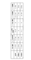
(第2具体例のリーチ判定乱数変更2の処理)上述第1具体例では、判定値A及びBを交互にリーチ発生判定に利用したが、図14の第2具体例のリーチ判定乱数変更2ルーチンの通り、判定値Bによるリーチ変動を所定回数表示(ここでは3回)した後に、判定値Aに切り替えるものである。例えば、1回目のリーチまでは判定値Aを用い、その後3回の実行されるリーチまでは判定値Bを用い、その後再び判定値Aを用い、そして、それらの処理を繰り返す。図14において、S510〜560は、前述図12のS310〜360と同様の処理である。しかし、第2具体例ではS560の後、カウンタCI(初期値は0)を1に設定し(S570)、リーチ発生判定(S540)を実行しリターンに抜ける。S550で否定判断の場合、前回のリーチは判定値Aを用いなかった即ち判定値Bを用いた場合であり、カウンタCIが3であるか否か、即ち判定値Bが3回連続して用いられたか否かを判定し(S580)、否定判断の場合即ち判定値Bが3回連続して用いられるには到らない場合、つまり、判定値Bが1回又は2回連続して用いられた場合、カウンタCIを1インクリメントした後(S595)、リーチ発生判定(S540)を実行しリターンに抜ける。S580で肯定判断即ち判定値Bが3回連続して用いられた場合、カウンタCIを初期値0に設定した後(S590)、リーチの履歴テーブルをクリアし(S600)、リーチ発生判定(S540)を実行しリターンに抜ける。こうして、判定値ABBBの順序でリーチが発生し、リーチ履歴がクリアされ、その後、同様な処理を繰り返す。この結果、例えば、図15の一覧表の通り、1回目のリーチは判定値Aにより変動時間が5秒行われ、2回目のリーチは判定値Bにより変動時間が10秒行われ、3回目のリーチは判定値Bにより変動時間が7秒行われ、4回目のリーチは判定値Bにより変動時間が30秒行われ、5回目のリーチは判定値Aにより変動時間が20秒行われ、以後同様な処理が行われる。それらリーチとリーチの間は、リーチとならない変動停止が適宜介在することもあることは無論であり該図表では省略している。なお、上記具体例では最初のリーチまでは判定値Aを用いたが、これを複数回(例えば、2回、3回…)のリーチまでは判定値Aを用いて行っても良い。
(Processing of Reach Determination
以上述べた通り、第2具体例によれば、図柄制御基板32bによるリーチ判定確率制御によって、まず1回目のリーチ発生迄は判定値Aによりリーチ発生を決定するので、リーチの発生確率は低いがリーチ信頼度は高く、2回目から4回目までのリーチ発生迄は判定値Bにより決定するので、リーチ発生確率は高いがリーチ信頼度は低くしかもリーチの集中度(発生頻度)が高まり、さらに、5回目のリーチ発生迄は判定値Aに戻り決定するので、リーチの発生確率は低いがリーチ信頼度は高い。つまり所定回数判定値Bを連続して採用することで、リーチの発生頻度は高まりリーチが集中し、その後、判定値Aの採用によりリーチからの大当りの信頼度が高くなり遊技者の満足度が高くなり、遊技者の期待に的確に応じることができる。また2回から4回目までのリーチについては短期間で発生しやすいので5回目のリーチを発生させようと遊技者は躍起になり趣向性が高まる。
As described above, according to the second specific example, the reach determination probability is controlled by the determination value A until the first reach is generated by the reach determination probability control by the
(第3具体例のリーチ判定乱数変更3の処理)前記第2具体例では、判定値Bを所定回数用いたが、この所定回数を乱数でランダムに決定しても良い。例えば、1回目のリーチまでは判定値Aを用い、その後ランダムに抽選された所定回数K回目のリーチまで判定値Bを用い、その後再び判定値Aを用い、そして、それらの処理を繰り返す。図16において、S610〜700は、前述図14のS510〜600と同様の処理である。しかし、第3具体例では、図16の通り、S661でカウンタ上限値Kを乱数値0〜5(乱数値0〜5はリーチ上限値3回からリーチ上限値8回までに各々対応し、それらの範囲は適宜変更可能)によって1つの値を抽選し、S662でこの乱数値に対応する回数をカウンタ上限値Kに設定し、さらに、S680でカウンタCIをカウンタ上限値Kと比較する処理が追加及び変更となっている。
(Processing of Reach Determination
以上述べた通り、第3具体例によれば、図柄制御基板32bによるリーチ判定確率制御によって、2回目からK+1回目までのリーチ発生迄は判定値Bにより決定し、且つ、判定値Bを用いる回数がランダムに変化するので、リーチの集中度がランダムに変化し、遊技者の予測がつかない面白さが生じる。
As described above, according to the third specific example, by the reach determination probability control by the
(第4具体例のリーチ判定乱数変更4の処理)以上の第1具体例ないし第3具体例では、主制御基板30から受信した特別図柄の変動時間に従ってリーチ変動を行ない、判定値A及びBを適宜に切換制御し、リーチを集中発生させる場合は、特別図柄の変動時間に関係なく判定値の多い方でリーチ画像を所定回数発生させたものである。しかし、変動タイムコードによってリーチ判定乱数の判定値A及びBの範囲の採択に影響を及ぼすようにする処理を可能とし、リーチ決定処理を、主制御基板30から送信されてくる変動タイムコードが示す変動時間に応じてリーチ画像を表示するか否かを決定することも可能である。例えば、リーチを集中的に発生させる場合、特別図柄の変動時間に関係なく判定値の範囲の広い方でリーチを所定回数発生させ、その後においては、変動時間が長く且つ判定値の範囲が少ない方のリーチ判定乱数でリーチを発生させる構成、或いは、特別図柄の変動時間の長い場合にだけリーチを発生させる構成等の様々な構成を採用可能である。この第4具体例では、リーチ判定乱数の判定値A及びBを、特別図柄の変動時間に応じて増減する処理とする。例えば、変動時間を10秒以上の場合に判定値の範囲を拡大してリーチ変動を多くし、10秒以下の場合は判定値の範囲を狭小に設定する等、変動時間に従ってリーチの発生頻度を決定する。例えば、図17のテーブルの通り、(1)変動時間が10秒以下の場合、判定値Aは0、判定値Bは0〜5、(2)変動時間が10〜20秒の場合、判定値Aは0,1、判定値Bは0〜10、(3)変動時間が20〜30秒の場合、判定値Aは0,1,2、判定値Bは0〜15、(4)変動時間が30秒以上の場合、判定値Aは0,1,2,3、判定値Bは0〜20に設定してある。図18の通り、まず変動タイムコードを主制御基板30から受信したか否かを判定し(S710)、肯定判断なら現在判定値A又はBいずれを使用しているのかを読み取り(S720)、変動タイムコード及び現在の使用すべき判定値A又はBに対応する判定値を図17のテーブルから読み取り(S730)、リターンに抜ける。S710で否定判断の場合、リターンに抜ける。
(Processing of Reach Determination Random Number Change 4 in the Fourth Specific Example) In the above first specific example to third specific example, the reach variation is performed according to the variation time of the special symbol received from the
以上の第4具体例によれば、特別図柄の変動時間が長ければリーチの集中度(発生頻度)が高まるので、変動時間が長くとも遊技者は画面に飽きない。また、大当りになる場合は、変動時間が長く決定される制御が行われるのが通常であるので、遊技者が変動時間の長さから大当りがくることを期待できる。さらに判定値Bを用いることよりリーチが集中したとしても、判定値Aに戻すことで、リーチの信頼性を高めることができる。 According to the above fourth specific example, the reach concentration (occurrence frequency) increases if the variation time of the special symbol is long, so that the player does not get bored with the screen even if the variation time is long. In the case of a big hit, since control is usually performed in which the fluctuation time is determined to be long, it can be expected that the player will win a big hit from the length of the fluctuation time. Further, even if the reach is concentrated by using the determination value B, the reliability of the reach can be improved by returning to the determination value A.
(第5具体例のリーチ判定乱数変更5の処理)以上の第1具体例ないし第4具体例では判定値A及びBの2種類であったが、これを3種類以上とするリーチ判定乱数変更処理が可能である。例えば、図19の通り、リーチ判定乱数の取り得る値の範囲は0〜29、3種類の判定値A、B及びCはリーチを発生させる値である。判定値Aの取り得る範囲は0の1個でリーチ判定確率は1/30、判定値Bの取り得る範囲は0〜1の2個でリーチ判定確率は2/30、判定値Cの取り得る範囲は0〜7の8個でリーチ判定確率は8/30に設定されている。そして、最初のリーチまでは判定値A、次の所定回数のリーチまでは判定値B、更に次の所定回数の判定値までは判定値C、そして、次のリーチまで判定値Aが設定されている。フローチャートは当業者であれば2種類の場合の処理から3種類以上の処理の場合も実施が可能であるので、説明は援用する。以上の第5具体例によれば、多段階に判定確率乱数を変更することができるので、きめ細かなリーチの発生頻度の制御が可能となる。
(Process of Reach Determination
(本実施形態の動作)前述した各処理を実行することにより、パチンコ機10は次のような動作を実行する。即ち、遊技者により操作される発射ハンドル24の回動量に応じて発射モータ33aにより遊技球が遊技盤22上に発射され、発射された遊技球が第1種始動口としての普通電動役物36に入賞すれば第1種始動口スイッチ36aにより検出され、特別図柄表示装置32のLCD32a画面上の特別図柄表示領域50a〜50c(図6参照)に特別図柄を所定時間変動表示した後に静止表示するよう働く。主制御基板30から図柄制御基板32bへ図柄に関するコマンド等が送信され、図柄制御基板32bでは前述の通りリーチ発生の判定を行って、LCD32a画面上への特別図柄、背景図柄などの画像を表示するように画像制御が実行される。特別図柄に関しては、まず左図柄が静止表示され、次に右図柄が静止表示され、右図柄と左図柄が一致しない場合は外れが確定し、その後、中図柄が静止表示される。右図柄と左図柄が一致した場合(例えば7?7)はリーチとなり、中図柄が変動した後に静止表示する。この静止表示した中図柄が右及び左図柄と一致しない場合はリーチ外れとなる(例えば727)。一方、特別図柄がこの静止表示した特別図柄が予め定められた特定図柄、例えば、前記リーチの後、全ての特別図柄が一致した場合(「777」等の3桁同一図柄)を表示すると大当り状態として、その後、遊技者に有利なゲーム内容を提供する。前述の通り、大当り状態となるか否かは、主制御基板30により遊技球が第1種始動口スイッチ36aにより検出されたとき抽出される当否決定乱数の値が所定値であるか否かにより決定される。また、リーチとなるか否かは、図柄制御基板32bによりリーチ判定乱数の値が判定値であるか否かにより決定される。
(Operation of this embodiment) By executing the above-described processes, the
こうして大当り状態となると、大入賞口40が約30秒間又は遊技球が10個入賞したことがカウントスイッチ40bにより検出されるまでいずれか早く経過する時まで開放され、このとき大入賞口40内に入賞した遊技球が特別領域を通過したことがVスイッチ40aにより検出されると一旦大入賞口40が閉鎖された後に再び開放され、この開放動作を最大16回繰り返す。通常、遊技球1個の入賞に対して15個の遊技球が賞球として払い出すよう構成しているので、1回の大当り状態が発生すると、約2400(=15×10×16)個の遊技球を賞球として獲得することができる。この賞球排出動作は、賞球制御基板31が実行する。尚、大入賞口40の特別領域を開閉するVソレノイド40dは、特別領域に遊技球が1個通過すると特別領域を閉鎖するためのものである。
In this way, when the big hit state is reached, the big winning
(本実施形態の効果)以上、詳細に説明した本実施形態によると、主制御基板30は図柄制御基板32bに図柄表示コマンド等の各種コマンドを送信するだけであり、該送信されたデータに加えて、図柄制御基板32bが独自にリーチを実行するか否かを決定した上で画像制御データを生成する。従って、主制御基板30のリーチ制御の負担が大いに軽減される。また、リーチ判定確率の確率の高い方により所定回数リーチ画像を表示することで意図的にリーチを集中させ、その後、リーチ判定確率の確率の低い方を用いることで、強制的にリーチの信頼度を高める制御を実行する。従って、リーチの発生頻度が高まれば高まるほど、リーチの信頼度が高まることとなり、遊技者の趣向はいやがうえでも高まることになる。画像制御基板32bでリーチ変動を実行するか否かを決定するので、リーチ変動を連続で発生させたり、変動回数に従って発生させたりする等自由にリーチ画像を表示制御することができる。
(Effects of the present embodiment) According to the present embodiment described in detail above, the
尚、本発明は、前述した具体例に何等制限されるものではなく、本発明の意図する範囲内で実施変更可能なことは言うまでもないことである。前述実施形態では、主制御基板30が図柄制御基板32bに当否判定データを送信するタイミングに起因して図柄制御基板32bがリーチ判定乱数を抽出したが、主制御基板30から図柄データその他のデータが送信されくるタイミングに起因してリーチ判定乱数を抽出しても良いし、更には、始動入賞コマンドが受信されたタイミングに起因してリーチ判定乱数を抽出することで、主制御基板30で始動入賞検出に同期したタイミングとしても良い。この場合、主制御基板30で更新され抽出される当否乱数と同じ構成のリーチ乱数を図柄制御基板32bで更新し抽出する構成とし、リーチ乱数の判定値に当否判定値を含む構成としても良い。
The present invention is not limited to the specific examples described above, and it goes without saying that the present invention can be modified within the intended scope of the present invention. In the embodiment described above, the
10…パチンコ機 22…遊技盤 24…発射ハンドル
24a…タッチスイッチ 30…主制御基板 31…賞球制御基板
32…特別図柄表示装置 32a…LCDパネルユニット(LCD)
32b…図柄表示装置制御基板(図柄制御基板)
33…発射制御基板 34…ランプ制御基板
35…音制御基板 36…普通電動役物(始動口)
36a…第1種始動口スイッチ 37…普通図柄表示装置
40…大入賞口 40a…役物連続作動スイッチ(VSW)
40b…(テン)カウントスイッチ(カウントSW)
50a,50b,50c…特別図柄表示領域
52…背景画面 hero、bad…キャラクタ
DESCRIPTION OF
32b ... design display control board (design control board)
33 ...
36a ... First-type
40b ... (ten) count switch (count SW)
50a, 50b, 50c ... Special
Claims (2)
前記条件成立判定手段により抽出された前記当否乱数の値が所定値である場合には遊技者に有利なゲームが実行される旨の有利報知画像、条件が成立しない場合には有利なゲームが実行されない旨の不利報知画像を表示する報知画像表示手段を備えた画像制御基板と、
前記遊技制御基板に、
前記報知画像表示手段により表示される画像の変動時間を前記入球に起因して複数の変動時間の中から決定する変動時間決定手段と、
該変動時間決定手段により決定された変動時間を示すデータ及び前記条件成立判定手段により抽出された前記当否乱数の値が所定値であるか否かを示す当否データを前記画像制御基板に送信するデータ送信手段と、
を備え、前記画像制御基板の報知画像表示手段は、受信した前記変動時間を示すデータに従って前記有利報知画像又は前記不利報知画像を変動表示する遊技機であって、
前記画像制御基板に、
受信した前記当否データに基づき遊技者に有利なゲームを実行しないと判定したとき、 前記有利報知画像が成立する前提条件となるリーチ画像を表示するか否かをリーチ乱数の抽出により決定するリーチ決定手段と、
該リーチ決定手段によりリーチ画像を表示すると決定された場合には、該リーチ画像を含む前記不利報知画像を決定し、該不利報知画像の画像制御データを生成して該決定された不利報知画像を受信した前記変動時間に従って変動表示するリーチ画像表示手段と、
を備え、
前記画像制御基板と前記遊技制御基板との送信は、前記遊技制御基板からのみ送信することができる一方向通信であり、
前記リーチ乱数は、前記受信した変動時間を示すデータが長い変動時間を示している場合、変動時間が短い場合よりリーチ発生確率が高く、
前記画像制御基板の前記リーチ画像表示手段が前記リーチ画像を変動表示するとき、前記リーチ画像に伴う制御を前記遊技制御基板は行わない、
ことを特徴とする遊技機。 A game control board having condition establishment determination means having a random number for determining whether or not to execute a game advantageous to the player due to the entry of the game ball;
An advantageous notification image that a game advantageous to the player is executed when the value of the success / failure random number extracted by the condition establishment determining means is a predetermined value, and an advantageous game is executed when the condition is not established An image control board provided with a notification image display means for displaying a disadvantage notification image indicating that
In the game control board,
Fluctuation time determination means for determining a fluctuation time of an image displayed by the notification image display means from a plurality of fluctuation times due to the entry,
Data indicating the variation time determined by the variation time determination means and data for transmitting to the image control board the success / failure data indicating whether or not the value of the success / failure random number extracted by the condition satisfaction determination means is a predetermined value. A transmission means;
The notification image display means of the image control board is a gaming machine that variably displays the advantage notification image or the disadvantage notification image according to the received data indicating the variation time,
On the image control board,
Reach determination for determining whether or not to display a reach image as a precondition for establishing the advantage notification image when it is determined not to execute a game advantageous to the player based on the received success / failure data Means,
When the reach determination means determines to display the reach image, the disadvantage notification image including the reach image is determined, image control data of the disadvantage notification image is generated, and the determined disadvantage notification image is displayed. Reach image display means for variably displaying according to the received variation time;
Bei to give a,
Transmission between the image control board and the game control board is a one-way communication that can be transmitted only from the game control board,
The reach random number has a higher reach probability than the case where the variation time is short when the received data indicating the variation time indicates a long variation time,
When the reach image display means of the image control board displays the reach image variably, the game control board does not perform the control associated with the reach image.
A gaming machine characterized by that.
前記条件成立判定手段により抽出された前記当否乱数の値が所定値である場合には遊技者に有利なゲームが実行される旨の有利報知画像、条件が成立しない場合には有利なゲームが実行されない旨の不利報知画像を表示する報知画像表示手段を備えた画像制御基板と、
前記遊技制御基板に、
前記報知画像表示手段により表示される画像の変動時間を前記入球に起因して複数の変動時間の中から決定する変動時間決定手段と、
該変動時間決定手段により決定された変動時間を示すデータ及び前記条件成立判定手段により抽出された前記当否乱数の値が所定値であるか否かを示す当否データを前記画像制御基板に送信するデータ送信手段と、
を備え、前記画像制御基板の報知画像表示手段は、受信した前記変動時間を示すデータに従って前記有利報知画像又は前記不利報知画像を変動表示する遊技機であって、
前記画像制御基板に、
受信した前記当否データに基づき遊技者に有利なゲームを実行しないと判定したとき、 前記有利報知画像が成立する前提条件となるリーチ画像を表示するか否かをリーチ乱数の抽出により決定するリーチ決定手段と、
該リーチ決定手段によりリーチ画像を表示すると決定された場合には、該リーチ画像を含む前記不利報知画像を決定し、該不利報知画像の画像制御データを生成して該決定された不利報知画像を受信した前記変動時間に従って変動表示するリーチ画像表示手段と、
を備え、前記画像制御基板の前記リーチ決定手段は、当選値の数を相違させた確率の相違するリーチ乱数を2種類以上有し、抽選された乱数値が前記当選値と一致すれば前記リーチ画像を表示することを決定し、該乱数の確率の高い方により所定回数リーチ画像が表示された後、該乱数の確率の低い方を用い、
前記リーチ乱数は、前記受信した変動時間を示すデータが長い変動時間を示している場合には変動時間が短い場合よりリーチ発生確率が高く、
前記所定回数をランダムとする、ことを特徴とする遊技機。 A game control board having condition establishment determination means having a random number for determining whether or not to execute a game advantageous to the player due to the entry of the game ball;
An advantageous notification image that a game advantageous to the player is executed when the value of the success / failure random number extracted by the condition establishment determining means is a predetermined value, and an advantageous game is executed when the condition is not established An image control board provided with a notification image display means for displaying a disadvantage notification image indicating that
In the game control board,
Fluctuation time determination means for determining a fluctuation time of an image displayed by the notification image display means from a plurality of fluctuation times due to the entry,
Data indicating the variation time determined by the variation time determination means and data for transmitting to the image control board the success / failure data indicating whether or not the value of the success / failure random number extracted by the condition satisfaction determination means is a predetermined value. A transmission means;
The notification image display means of the image control board is a gaming machine that variably displays the advantage notification image or the disadvantage notification image according to the received data indicating the variation time ,
On the image control board,
Reach determination for determining whether or not to display a reach image as a precondition for establishing the advantage notification image when it is determined not to execute a game advantageous to the player based on the received success / failure data Means ,
When the reach determination means determines to display the reach image, the disadvantage notification image including the reach image is determined, image control data of the disadvantage notification image is generated, and the determined disadvantage notification image is displayed. Reach image display means for variably displaying according to the received variation time;
And the reach determination means of the image control board has two or more types of reach random numbers having different probabilities of different numbers of winning values, and the reach if the lottery random number value matches the winning value. Decide to display an image, and after the reach image is displayed a predetermined number of times by the higher probability of the random number, the lower probability of the random number is used,
The reach random number has a higher reach occurrence probability than the case where the variation time is short when the received variation time data indicates a long variation time,
A gaming machine , wherein the predetermined number of times is random .
Priority Applications (1)
| Application Number | Priority Date | Filing Date | Title |
|---|---|---|---|
| JP2009192911A JP5017510B2 (en) | 2009-08-24 | 2009-08-24 | Game machine |
Applications Claiming Priority (1)
| Application Number | Priority Date | Filing Date | Title |
|---|---|---|---|
| JP2009192911A JP5017510B2 (en) | 2009-08-24 | 2009-08-24 | Game machine |
Related Parent Applications (1)
| Application Number | Title | Priority Date | Filing Date |
|---|---|---|---|
| JP2000223926A Division JP4636571B2 (en) | 2000-07-25 | 2000-07-25 | Game machine |
Related Child Applications (1)
| Application Number | Title | Priority Date | Filing Date |
|---|---|---|---|
| JP2010278618A Division JP4825950B2 (en) | 2010-12-14 | 2010-12-14 | Game machine |
Publications (3)
| Publication Number | Publication Date |
|---|---|
| JP2009273918A JP2009273918A (en) | 2009-11-26 |
| JP2009273918A5 JP2009273918A5 (en) | 2011-02-17 |
| JP5017510B2 true JP5017510B2 (en) | 2012-09-05 |
Family
ID=41439840
Family Applications (1)
| Application Number | Title | Priority Date | Filing Date |
|---|---|---|---|
| JP2009192911A Expired - Lifetime JP5017510B2 (en) | 2009-08-24 | 2009-08-24 | Game machine |
Country Status (1)
| Country | Link |
|---|---|
| JP (1) | JP5017510B2 (en) |
Families Citing this family (1)
| Publication number | Priority date | Publication date | Assignee | Title |
|---|---|---|---|---|
| JP5807298B2 (en) * | 2010-08-19 | 2015-11-10 | 株式会社ソフイア | Game machine |
Family Cites Families (8)
| Publication number | Priority date | Publication date | Assignee | Title |
|---|---|---|---|---|
| JPH06210058A (en) * | 1993-01-14 | 1994-08-02 | Sophia Co Ltd | Game machine controller |
| JPH06246050A (en) * | 1993-02-22 | 1994-09-06 | Sophia Co Ltd | Game machine |
| JP3967395B2 (en) * | 1995-11-29 | 2007-08-29 | 株式会社ソフィア | Game machine |
| JPH09262345A (en) * | 1996-03-29 | 1997-10-07 | Samii Kk | Pachinko game machine |
| JP3986582B2 (en) * | 1996-04-18 | 2007-10-03 | 株式会社ソフィア | Game machine |
| JP4137263B2 (en) * | 1998-12-29 | 2008-08-20 | 株式会社三共 | Game machine |
| JP3789664B2 (en) * | 1998-12-29 | 2006-06-28 | 株式会社三共 | Game machine |
| JP2000202101A (en) * | 1999-01-13 | 2000-07-25 | Sankyo Kk | Game machine |
-
2009
- 2009-08-24 JP JP2009192911A patent/JP5017510B2/en not_active Expired - Lifetime
Also Published As
| Publication number | Publication date |
|---|---|
| JP2009273918A (en) | 2009-11-26 |
Similar Documents
| Publication | Publication Date | Title |
|---|---|---|
| JP4621831B2 (en) | Game machine | |
| JP3608606B2 (en) | Game machine | |
| JP4448907B2 (en) | Bullet ball machine | |
| JP2007038028A (en) | Pinball game machine | |
| JP4621830B2 (en) | Game machine | |
| JP2006000568A (en) | Game machine | |
| JP2005342262A (en) | Game machine | |
| JP2002102468A (en) | Game machine | |
| JP2002102465A (en) | Game machine | |
| JP2000288219A (en) | Game machine | |
| JP2005334362A (en) | Game machine | |
| JP4636571B2 (en) | Game machine | |
| JP2001286633A (en) | Pinball game machine | |
| JP5017510B2 (en) | Game machine | |
| JP2002306750A (en) | Game machine, computer program and recording medium | |
| JP4825950B2 (en) | Game machine | |
| JP3669567B2 (en) | Game machine | |
| JP2005342352A (en) | Game machine | |
| JP2000317078A (en) | Pinball game machine | |
| JP4882056B2 (en) | Game machine | |
| JP3674758B2 (en) | Bullet ball machine | |
| JP4224531B2 (en) | Bullet ball machine | |
| JP6959088B2 (en) | Pachinko machine | |
| JP2000308746A (en) | Game machine | |
| JP3416588B2 (en) | Ball game machine |
Legal Events
| Date | Code | Title | Description |
|---|---|---|---|
| A621 | Written request for application examination |
Free format text: JAPANESE INTERMEDIATE CODE: A621 Effective date: 20090916 |
|
| A521 | Written amendment |
Free format text: JAPANESE INTERMEDIATE CODE: A523 Effective date: 20101014 |
|
| A521 | Written amendment |
Free format text: JAPANESE INTERMEDIATE CODE: A523 Effective date: 20101220 |
|
| A871 | Explanation of circumstances concerning accelerated examination |
Free format text: JAPANESE INTERMEDIATE CODE: A871 Effective date: 20110217 |
|
| A131 | Notification of reasons for refusal |
Free format text: JAPANESE INTERMEDIATE CODE: A131 Effective date: 20110228 |
|
| A975 | Report on accelerated examination |
Free format text: JAPANESE INTERMEDIATE CODE: A971005 Effective date: 20110224 |
|
| A521 | Written amendment |
Free format text: JAPANESE INTERMEDIATE CODE: A523 Effective date: 20110411 |
|
| A131 | Notification of reasons for refusal |
Free format text: JAPANESE INTERMEDIATE CODE: A131 Effective date: 20110714 |
|
| A521 | Written amendment |
Free format text: JAPANESE INTERMEDIATE CODE: A523 Effective date: 20110818 |
|
| A131 | Notification of reasons for refusal |
Free format text: JAPANESE INTERMEDIATE CODE: A131 Effective date: 20111110 |
|
| A521 | Written amendment |
Free format text: JAPANESE INTERMEDIATE CODE: A523 Effective date: 20111216 |
|
| TRDD | Decision of grant or rejection written | ||
| A01 | Written decision to grant a patent or to grant a registration (utility model) |
Free format text: JAPANESE INTERMEDIATE CODE: A01 Effective date: 20120315 |
|
| A01 | Written decision to grant a patent or to grant a registration (utility model) |
Free format text: JAPANESE INTERMEDIATE CODE: A01 |
|
| A61 | First payment of annual fees (during grant procedure) |
Free format text: JAPANESE INTERMEDIATE CODE: A61 Effective date: 20120315 |
|
| R150 | Certificate of patent or registration of utility model |
Ref document number: 5017510 Country of ref document: JP Free format text: JAPANESE INTERMEDIATE CODE: R150 Free format text: JAPANESE INTERMEDIATE CODE: R150 |
|
| FPAY | Renewal fee payment (event date is renewal date of database) |
Free format text: PAYMENT UNTIL: 20150622 Year of fee payment: 3 |
|
| S531 | Written request for registration of change of domicile |
Free format text: JAPANESE INTERMEDIATE CODE: R313531 |
|
| FPAY | Renewal fee payment (event date is renewal date of database) |
Free format text: PAYMENT UNTIL: 20150622 Year of fee payment: 3 |
|
| R350 | Written notification of registration of transfer |
Free format text: JAPANESE INTERMEDIATE CODE: R350 |
|
| R250 | Receipt of annual fees |
Free format text: JAPANESE INTERMEDIATE CODE: R250 |
|
| R250 | Receipt of annual fees |
Free format text: JAPANESE INTERMEDIATE CODE: R250 |
|
| EXPY | Cancellation because of completion of term |