JP4970723B2 - Method and apparatus for switching semiconductor switch using multi-state drive circuit - Google Patents
Method and apparatus for switching semiconductor switch using multi-state drive circuit Download PDFInfo
- Publication number
- JP4970723B2 JP4970723B2 JP2004365877A JP2004365877A JP4970723B2 JP 4970723 B2 JP4970723 B2 JP 4970723B2 JP 2004365877 A JP2004365877 A JP 2004365877A JP 2004365877 A JP2004365877 A JP 2004365877A JP 4970723 B2 JP4970723 B2 JP 4970723B2
- Authority
- JP
- Japan
- Prior art keywords
- semiconductor switch
- state
- voltage
- drive
- time period
- Prior art date
- Legal status (The legal status is an assumption and is not a legal conclusion. Google has not performed a legal analysis and makes no representation as to the accuracy of the status listed.)
- Expired - Fee Related
Links
- 239000004065 semiconductor Substances 0.000 title claims description 86
- 238000000034 method Methods 0.000 title claims description 18
- 230000007704 transition Effects 0.000 claims description 15
- 230000008859 change Effects 0.000 claims description 12
- 230000005669 field effect Effects 0.000 claims description 2
- 229910044991 metal oxide Inorganic materials 0.000 claims description 2
- 150000004706 metal oxides Chemical class 0.000 claims description 2
- 238000001514 detection method Methods 0.000 claims 1
- 230000000977 initiatory effect Effects 0.000 claims 1
- 230000008901 benefit Effects 0.000 description 15
- 238000010586 diagram Methods 0.000 description 4
- 230000008878 coupling Effects 0.000 description 2
- 238000010168 coupling process Methods 0.000 description 2
- 238000005859 coupling reaction Methods 0.000 description 2
- 238000004519 manufacturing process Methods 0.000 description 2
- 230000002411 adverse Effects 0.000 description 1
- 230000007423 decrease Effects 0.000 description 1
- 230000000694 effects Effects 0.000 description 1
- 238000012986 modification Methods 0.000 description 1
- 230000004048 modification Effects 0.000 description 1
Images


Classifications
-
- H—ELECTRICITY
- H03—ELECTRONIC CIRCUITRY
- H03K—PULSE TECHNIQUE
- H03K17/00—Electronic switching or gating, i.e. not by contact-making and –breaking
- H03K17/16—Modifications for eliminating interference voltages or currents
- H03K17/161—Modifications for eliminating interference voltages or currents in field-effect transistor switches
- H03K17/162—Modifications for eliminating interference voltages or currents in field-effect transistor switches without feedback from the output circuit to the control circuit
- H03K17/163—Soft switching
- H03K17/164—Soft switching using parallel switching arrangements
-
- H—ELECTRICITY
- H03—ELECTRONIC CIRCUITRY
- H03K—PULSE TECHNIQUE
- H03K17/00—Electronic switching or gating, i.e. not by contact-making and –breaking
- H03K17/04—Modifications for accelerating switching
- H03K17/042—Modifications for accelerating switching by feedback from the output circuit to the control circuit
- H03K17/04206—Modifications for accelerating switching by feedback from the output circuit to the control circuit in field-effect transistor switches
-
- H—ELECTRICITY
- H03—ELECTRONIC CIRCUITRY
- H03K—PULSE TECHNIQUE
- H03K17/00—Electronic switching or gating, i.e. not by contact-making and –breaking
- H03K17/16—Modifications for eliminating interference voltages or currents
- H03K17/161—Modifications for eliminating interference voltages or currents in field-effect transistor switches
- H03K17/165—Modifications for eliminating interference voltages or currents in field-effect transistor switches by feedback from the output circuit to the control circuit
- H03K17/166—Soft switching
- H03K17/167—Soft switching using parallel switching arrangements
Description
本発明は一般に、半導体スイッチに関し、更に具体的には、本発明は、オフ状態からオン状態、或いはオン状態からオフ状態に切換えられる半導体スイッチに関する。 The present invention relates generally to semiconductor switches, and more specifically, the present invention relates to semiconductor switches that are switched from an off state to an on state, or from an on state to an off state.
半導体スイッチを使用する多くの電子回路では、回路効率を最大にすることが重要である。従って、高周波で切換えられる半導体デバイスを使用する電子回路では、オフ状態からオン状態及びオン状態からオフ状態に半導体スイッチを切換えることに伴う、多くの場合スイッチングロスと呼ばれる損失を最小にすることが重要である。 In many electronic circuits that use semiconductor switches, it is important to maximize circuit efficiency. Therefore, in electronic circuits that use semiconductor devices that can be switched at high frequencies, it is important to minimize the loss often referred to as switching loss associated with switching semiconductor switches from off to on and from on to off. It is.
半導体スイッチがオフ状態にあるときには、半導体スイッチを流れる電流は通常はほぼゼロであり、高電圧が半導体スイッチ両端に存在する。半導体スイッチがオフ状態からオン状態に切換えられると、半導体スイッチを流れる電流が増大し、半導体スイッチ両端に電圧降下が生じる。電力損失は、電圧と電流の積に等しいので、オフ状態からオン状態への切換え時に損失する総エネルギーは、オフ状態からオン状態への遷移に要する時間を最小にすることによって低減される。 When the semiconductor switch is in the OFF state, the current flowing through the semiconductor switch is normally almost zero, and a high voltage exists across the semiconductor switch. When the semiconductor switch is switched from the off state to the on state, the current flowing through the semiconductor switch increases, causing a voltage drop across the semiconductor switch. Since power loss is equal to the product of voltage and current, the total energy lost when switching from the off state to the on state is reduced by minimizing the time required to transition from the off state to the on state.
しかしながら、半導体スイッチがオフ状態からオン状態に切換わるのに要する時間を単純に低減させると、半導体スイッチがその一部をなす電子回路の他の回路の動作で問題が生じる可能性がある。一般にdv/dtと呼ばれる電圧の変化の増加率、及び、一般にdi/dtと呼ばれる電流の変化の増加率は、半導体スイッチが切換える毎に生じる電気雑音を増加させる。この電気雑音は、他の回路の動作に悪影響を及ぼす場合があり、従ってdv/dt及びdi/dtを制限し、許容できるレベルに電気雑音を維持することが望ましい場合が多い。スイッチングロスを最小にするだけでなく電気雑音を許容できるレベルに制限することへの必要性は、オフ状態からオン状態に半導体スイッチを切換えるためのドライブ信号を供給するドライブ回路の設計がトレードオフであることを意味している。 However, simply reducing the time required for the semiconductor switch to switch from the off state to the on state can cause problems in the operation of other circuits in the electronic circuit of which the semiconductor switch is a part. The rate of increase in voltage change, commonly referred to as dv / dt, and the rate of increase in current change, generally referred to as di / dt, increase the electrical noise that occurs each time the semiconductor switch is switched. This electrical noise can adversely affect the operation of other circuits, so it is often desirable to limit dv / dt and di / dt and maintain the electrical noise at an acceptable level. The need to not only minimize switching losses but also limit electrical noise to an acceptable level is a trade-off in the design of drive circuits that provide drive signals to switch semiconductor switches from off to on. It means that there is.
スイッチングロスを低減させることが望ましい箇所に半導体スイッチを使用し、dv/dt及びdi/dtを制限する電子回路は、スイッチング電源を含む。これらのスイッチング電源では、半導体スイッチをオフ状態からオン状態及びオン状態からオフ状態に切換えるためのドライブ信号を印加するために接続されたドライブ回路が、電源コントローラ集積回路の一部を形成する場合が多い。また、ドライブ回路は、集積回路に外付けの電源コントローラ集積回路とディスクリート部品とを備えることができる。 Electronic circuits that use semiconductor switches where it is desirable to reduce switching losses and limit dv / dt and di / dt include switching power supplies. In these switching power supplies, the drive circuit connected to apply a drive signal for switching the semiconductor switch from the off state to the on state and from the on state to the off state may form part of the power controller integrated circuit. Many. The drive circuit may include an external power controller integrated circuit and discrete components.
多段ドライブ回路によって半導体スイッチを切換えるための方法及び装置が開示される。1つの実施態様では、回路は、第1と第2の状態の間を切換えるように適合されている半導体スイッチを含む。第1の状態は、オフ状態又はオン状態の一方であり、第2の状態はオフ状態又はオン状態の他方である。また回路は、半導体スイッチに接続された複数のドライブ回路を含む。複数のドライブ回路は、半導体スイッチを第1の状態から第2の状態に切換えるための複数のドライブ信号を供給するよう接続される。更に回路は、半導体スイッチが第1の状態から第2の状態に切換えるときに半導体スイッチに複数のドライブ信号を供給するドライブ回路を選択するよう接続されたセレクタ回路を含む。 A method and apparatus for switching semiconductor switches with a multi-stage drive circuit is disclosed. In one embodiment, the circuit includes a semiconductor switch that is adapted to switch between first and second states. The first state is one of an off state and an on state, and the second state is the other of the off state and the on state. The circuit also includes a plurality of drive circuits connected to the semiconductor switch. The plurality of drive circuits are connected to supply a plurality of drive signals for switching the semiconductor switch from the first state to the second state. The circuit further includes a selector circuit connected to select a drive circuit that supplies a plurality of drive signals to the semiconductor switch when the semiconductor switch switches from the first state to the second state.
本発明の更に別の特徴及び利点は、以下に示される詳細な説明、図、及び請求項から明らかになるであろう。
本発明は実施形態によって詳細に例証されるが、添付図面により限定されるものではない。
改良された半導体スイッチ多段ドライブ回路を実施する装置及び方法の実施形態が開示される。以下の説明において、本発明を完全に理解できるように多数の特定の詳細が説明される。しかしながら、本発明を実施するために特定の詳細を利用する必要がないことは、当業者にとは明らかであろう。この実施に関する公知の方法は、本発明を曖昧にしないように詳細には説明していない。
Additional features and advantages of the invention will be apparent from the detailed description, figures and claims set forth below.
The present invention is illustrated in detail by the embodiments, but is not limited by the attached drawings.
Embodiments of apparatus and methods for implementing an improved semiconductor switch multi-stage drive circuit are disclosed. In the following description, numerous specific details are set forth in order to provide a thorough understanding of the present invention. However, it will be apparent to one skilled in the art that the specific details need not be utilized to practice the invention. Known methods for this implementation have not been described in detail so as not to obscure the present invention.
本明細書を通して、「1つの実施形態」又は「ある実施形態」という表現は、実施形態に関連して説明された特定の特徴、構造、或いは特性が本発明の少なくとも1つの実施形態に含まれることを意味する。従って、本明細書を通して様々な箇所での「1つの実施形態では」又は「ある実施形態では」という語句の出現は、必ずしも同じ実施形態に対して全て言及しているわけではない。更に、特定の特徴、構造、或いは特性は、1つ又はそれ以上の実施形態においてどのような適切な方法にも組み合わせることができる。 Throughout this specification, the expression "one embodiment" or "an embodiment" includes a particular feature, structure, or characteristic described in connection with the embodiment is included in at least one embodiment of the invention. Means that. Thus, the appearances of the phrases “in one embodiment” or “in an embodiment” in various places throughout this specification are not necessarily all referring to the same embodiment. Furthermore, the particular features, structures, or characteristics may be combined in any suitable manner in one or more embodiments.
次に、本発明の教示に従ってこのような回路を実現するための改良された半導体スイッチ多段ドライブ回路及び方法を説明する。本発明の実施形態は、オフ状態からオン状態、及び/又はオン状態からオフ状態に切換える半導体スイッチのスイッチングロスを低減する方法及び装置を含む。本明細書を通して、nチャネル金属酸化膜電界効果トランジスタ(MOSFET)半導体スイッチのドライブ回路が実施形態によって示されている。しかしながら開示される技術は、この開示の利点を有する当業者にはよく知られているpチャネルMOSFET及び他のタイプの半導体スイッチに適用することができる。同様に、この開示を通して特にオフ状態からオン状態への半導体スイッチのスイッチング遷移に対して言及されている。説明される技術がオン状態からオフ状態への半導体スイッチのスイッチング遷移にも適用できることは、本開示の恩恵を有する当業者には理解されるであろう。 An improved semiconductor switch multi-stage drive circuit and method for implementing such a circuit in accordance with the teachings of the present invention will now be described. Embodiments of the present invention include a method and apparatus for reducing switching loss of a semiconductor switch that switches from an off state to an on state and / or from an on state to an off state. Throughout this specification, a drive circuit of an n-channel metal oxide field effect transistor (MOSFET) semiconductor switch is illustrated by embodiments. However, the disclosed technique can be applied to p-channel MOSFETs and other types of semiconductor switches well known to those skilled in the art having the benefit of this disclosure. Similarly, throughout this disclosure, reference is made specifically to the switching transition of a semiconductor switch from an off state to an on state. Those skilled in the art having the benefit of this disclosure will appreciate that the described techniques can also be applied to switching transitions of semiconductor switches from an on state to an off state.
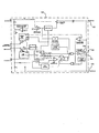
図1は、本発明の実施形態による、ドライブ回路の恩恵を受けることのできる電源コントローラ101の1つの実施形態のブロック図を示す。電源コントローラ101は、ドライブ回路103を含む。ドライブ回路103は、MOSFET半導体スイッチ104のゲート端子と呼ばれることが多いドライブ端子106にドライブ信号を加えて、MOSFET104をオフ状態からオン状態へ及びオン状態からオフ状態へ切換える。MOSFET104は更に、電圧基準すなわちソース端子105及びドレイン端子102を含む。
FIG. 1 shows a block diagram of one embodiment of a
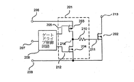
図2は、MOSFET202をドライブするよう接続された回路の概略図を示す。この回路は、MOSFET202をオフ状態からオン状態に切換えるドライブ信号をドライブ端子211に供給するよう接続されたpチャネルMOSFET203を含むドライブ回路201を備える。ドライブ回路201は更に、MOSFET202をオン状態からオフ状態へ切換えるドライブ信号をドライブ端子211に供給するよう接続されたnチャネルMOSFET204を備える。本開示の他のものと同様に、以下の説明は、オフ状態からオン状態へのMOSFET202のスイッチング遷移に集中しているが、当業者であれば、本教示はオン状態からオフ状態へのスイッチングにも同様に関連することが理解されるであろう。
FIG. 2 shows a schematic diagram of a circuit connected to drive
MOSFET202がオフ状態からオン状態に切換わる速度は、1つには電源レール206とゲート211間のインピーダンスによって支配される。このインピーダンスが低いほど、MOSFET202のオフ状態からオン状態への遷移が速くなる。ドライブ回路の全インピーダンスは、pチャネルMOSFET203のオン抵抗にインピーダンス210を加えたものである。pチャネルMOSFET203のオン抵抗は、そのソース端子206に対してゲート205のノードの電圧によって影響を受ける。図2に示された概略図では、ゲートドライブ制御回路209が、端子205で固定電圧を与えてMOSFET203をターンオンする。このタイプのドライブ回路では、MOSFET203のオン抵抗は、MOSFET202がオフ状態からオン状態に切換えられる間はほぼ一定である。
The speed at which the
しかし、MOSFET202がオフ状態からオン状態へ切換えるときに、ゲートドライブ制御回路209が、第1の時間期間で端子205に第1の電圧を加え、且つ第2の時間期間で第2の電圧を加える場合には、ドライブ回路201のより高度な制御を実現することができる。このように、ドライブ回路201のインピーダンスは、以下に説明されるようにオフ状態からオン状態へのMOSFET202の遷移中に変化する場合がある。
However, when the
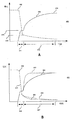
図3は、MOSFET203のようなMOSFETに典型的な出力特性曲線と一般にされる2つの曲線301を示す。これらの曲線は、端子206と214との間に流れる電流の関数として端子206と214との間の電圧を示している。MOSFET203は、306で示される領域で動作するように通常は設計されている。この領域での出力特性は、電圧と電流との間にほぼ線形の関係を示しており、従って実質的に抵抗特性を示す。
FIG. 3 shows two
曲線303は、ソース端子206に対してゲート端子205に印加された特定電圧での出力特性を示す。曲線302は、ゲート端子205とソース端子206との間に印加されたより高い相対電圧での出力特性を示す。
A
本明細書では、曲線302は、十分に強化された出力特性と呼ばれ、温度及び製造のばらつきによってMOSFET203のゲート閾値電圧が大きく変化する曲線303の部分的に強化された特性に比べて、製造のばらつき及び温度に関して比較的安定した特性である。図に示すように、特性302は領域306でより急な勾配を有し、従って曲線303より低い抵抗を示す。1つの実施形態において、この低い抵抗は、本発明の教示に従って、上記に説明されたMOSFET202のオフ状態からオン状態への遷移中にドライブ回路201のインピーダンスが変化することができる第2の時間期間に使用される。このようなドライブ回路201のインピーダンスが変化する利点は、図4A、4Bに示されている。
In this specification,
図4Aの曲線400は、MOSFET202がオフ状態からオン状態へ切換えるときの基準電圧端子208に対する、ゲート端子211とドレイン端子213それぞれのゲート電圧曲線403とドレイン電圧曲線402をそれぞれ示す。ドレイン端子213の電圧は、ゲート端子211の電圧よりも普通ははるかに高い値になるが、本明細書ではゲート電圧曲線403と同じ電圧スケールで示されている。図4A、4Bの曲線400、401は、縮尺通りに描かれていないが、本開示の対象であるゲートドライブ回路の作用を示すために使用される。図4A、4Bに示されるスイッチング波形をもたらす正確な半導体スイッチパラメータは、本発明の教示をあいまいにしないように、本明細書には示されていないが、本開示の恩恵を受ける当業者には明らかであろう。
第1の時間期間411の間に、ゲート電圧曲線403は上昇し、ドレイン電圧曲線402は下降し始める。MOSFET202のゲート211の静電容量の特性に起因して、MOSFET202のゲート211の電圧は、ドレイン213の電圧が値416に達するまでは電圧レベル413に一時的にクランプされる。MOSFET202のゲート211の電圧のクランプがとれると、第2の時間期間412内で最終値414まで上昇し、その継続時間は、上記のようにドライブ回路201のインピーダンスによって支配される。図示された実施形態に示されるように、第2の時間期間412は第1の時間期間411の後であり、ドレイン電圧曲線402がすでに下降が開始し終わった後に開始する。第2の時間期間412全体を通して、ゲート電圧曲線403が上昇すると、全ゲート電圧414がゲート211に存在するときにMOSFET202のオン抵抗が最小値まで下降する。
During the
図4Bは、図2に関して上述されたゲートドライブ回路インピーダンスを変化させる影響を示す。図4Aと同様に、図4Bの曲線401は、MOSFET202がオフ状態からオン状態へ切換わるときに基準電圧端子208に対して、それぞれゲート端子211とドレイン端子213のゲート電圧曲線404とドレイン電圧曲線409をそれぞれ示している。ドライブ回路インピーダンスが第2の時間期間407の最初で低くなる場合には、第2の時間期間407中のMOSFET202のゲート電圧曲線404の上昇時間は、ゲート電圧曲線410で示される時間まで短縮され、MOSFET202のドレイン電圧は、曲線405によって示されるようにより急速に下降するので、曲線406によって示される以前の特性に対してオフ状態からオン状態への遷移中の損失が低減される。図示された実施形態に示されるように、第2の時間期間407は第1の時間期間408の後にあり、ドレイン電圧曲線409が既に下降開始が終わった後に開始する。第2の時間期間が開始する時間は、ドライブ回路インピーダンスが変化しない上述の最も単純なドライブ回路の動作を説明するのにも使用されていたので図2には示されていないが、例えばゲートドライブ回路209をMOSFET202のゲート端子211に接続することによるような、幾つかの方法で感知することができる。
FIG. 4B illustrates the effect of changing the gate drive circuit impedance described above with respect to FIG. Similar to FIG. 4A,
しかしながら、MOSFET202がオフ状態からオン状態へ遷移している間、第1の時間期間で端子205に第1固定電圧を供給し、及び第2の時間期間で第2固定電圧を供給することによってドライブ回路201のインピーダンスを低減させることは、大量生産の回路で使用される場合に一貫性のない結果をもたらす。MOSFET203の出力特性は、温度及び製造のばらつきによってかなり変動する。このため、動作中のこの回路の正確な性能、従って得られるはずの利点を予測することは難しい。
However, while
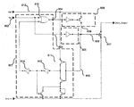
図5は、本発明の教示による恩恵を受ける回路の別の実施形態を示す。第1ドライブ回路501は、pチャネルMOSFET503及びnチャネルMOSFET504を含む。第2ドライブ回路518は、pチャネルMOSFET513及びnチャネルMOSFET514を含む。本明細書では、インピーダンス510は、ドライブ回路501、518の両方とも同じインピーダンスを与えるので、これらの外側に示されている。ゲートドライブ制御及びセレクタ回路509は、入力507と、MOSFET503、504、513、514を別々にドライブするための個別の出力を有する。
FIG. 5 illustrates another embodiment of a circuit that would benefit from the teachings of the present invention. The
動作中、オフ状態からオン状態へのMOSFET502のスイッチングの間、MOSFET503が第1の時間期間にターンオンされ、第1ドライブ信号を供給する。次にセレクタ回路509が第2の時間期間の間にMOSFET513をターンオンし、第2ドライブ信号を供給する。図5に示される実施形態では、ゲートドライブ制御及びセレクタ回路509は、接続517を使用してMOSFET502のゲート511に接続されている。1つの実施形態では、この接続は、ゲートドライブ制御及びセレクタ回路509が第2ドライブ回路518をターンオンする正確な時間を感知することができる1つの方法を提供する。
In operation, during switching of
ドライブ又はゲート端子511と基準電圧又はソース端子508との間の電圧が回路509の設計で定められた電圧閾値に達すると、第2の時間期間が上記で図4に関して説明されたように開始する。実施形態に応じて、回路509内のセレクタ回路が、第1の時間期間の終わりにMOSFET503をターンオフするか、又は第1と第2の時間期間の両方でMOSFET503をオンのまま保持するように設計することができる。
When the voltage between the drive or
図5に示された実施形態は、MOSFET205のゲート電圧がドライブ回路201のインピーダンスを変えるために変化する図2に関して説明された方式とは異なる。例えば、1つの相違点は、1つの実施形態の両方のMOSFET503、513は、十分強化されるようにドライブされ、従って図3の曲線302に関して上述された十分に強化された出力特性の比較的安定した特性を示すので、第1の時間期間から第2の時間期間へのインピーダンス変化の程度を正確に予測できることである。更に、ドライブ回路501と518の結合インピーダンスは、例えば、MOSFET503を第2の時間期間の持続時間の間にターンオフするか、或いはオンのままにすることができるので、図2のドライブ回路よりも制御が容易である。
The embodiment shown in FIG. 5 differs from the scheme described with respect to FIG. 2 in which the gate voltage of
1つの実施形態においては、2つより多い複数のドライブ回路が用いられる場合に、第1と第2の時間期間中にオン及びオフにされるMOSFETの種々の組合せを選択することによって可能な結合インピーダンスの変化において更に高い融通性が存在する。全ての場合に、MOSFETが十分強化された特性を有してドライブされるので、オフ状態からオン状態へ切換わるときの出力特性、従ってMOSFET502の特性は、容易に予測される。2つより多い複数のドライブ回路が用いられる場合には、MOSFET502が、複数のドライブ回路の結合インピーダンスが変化することになる複数の期間を使用してオフ状態からオン状態に切換えることができることも明らかである。本開示の以下の説明は、本発明の教示を曖昧にしないために2つのドライブ回路の使用に向けられる。
In one embodiment, possible coupling by selecting different combinations of MOSFETs that are turned on and off during the first and second time periods when more than two drive circuits are used. There is even greater flexibility in changing impedance. In all cases, the MOSFET is driven with sufficiently enhanced characteristics so that the output characteristics when switching from the off state to the on state, and thus the characteristics of the
図6は、本発明の教示の恩恵を受ける回路の別の実施形態を示す。ここでもやはり、2つのドライブ回路601、618は、MOSFET602のゲートに第1と第2のドライブ信号をそれぞれ別々に供給する第1と第2ドライブ回路として機能する。しかしながら、第2の時間期間の開始を決定するのに使用される感知信号は、ゲートドライブ制御及びセレクタ回路609から接続617を介してMOSFET602のドレイン613に接続されている。図4Bに関して、これはまた、MOSFET602両端の電圧の1時間期間にわたるMOSFET602両端の電圧降下の急激な変化(dv/dt)の遷移415が終わった時間、或いは、MOSFET602両端の電圧がdv/dt遷移415後に電圧閾値まで低下するか又はこれに達した時間を検出する1つの方法であることが分かる。この点で、本発明の教示によってMOSFET602両端の電圧が特性406ではなく特性405に従うのを確実にするのは、第2の時間期間407を開始する正確な時間である。
FIG. 6 illustrates another embodiment of a circuit that would benefit from the teachings of the present invention. Again, the two
図7は、本発明の教示による恩恵を受ける回路の別の実施形態を示す。図示された実施形態に示されるように、電流センサー720は、MOSFET702に接続され、MOSFET702のドレイン端子713とソース708端子間に流れる電流を感知する。電流センサー720は、本発明の教示を曖昧にしないために本明細書で示されていない公知の種々の技術を使用して、MOSFET702を通って流れる電流を感知することができる。電流センサー720は、接続717を介してゲートドライブ制御及びセレクタ回路709に接続される。このようにオフ状態からオン状態への遷移中にMOSFET702に流れる電流を感知することによって、回路709内のセレクタ回路は、この情報を使用してMOSFET702に流れる電流が第2の時間期間407が開始する正確な時間を決定するための電流閾値を越える時間を感知するように設計することができる。
FIG. 7 illustrates another embodiment of a circuit that would benefit from the teachings of the present invention. As shown in the illustrated embodiment, the
図8は、本発明の教示の恩恵を受ける回路の別の実施形態を示す。図示された実施形態に示されるように、ゲートドライブ及びセレクタ回路801は、入力802と2つの出力803、804とを有する。出力803は、第1ドライブ回路805への入力である。ゲートドライブ及びセレクタ回路801は、接続810を介して第1ドライブ回路805の出力を感知するように接続されている。ドライブ回路805は、半導体スイッチ或いはMOSFET807のドライブ端子すなわちゲート806をオフ状態からオン状態に切換えるようドライブし、且つオン状態からオフ状態へドライブするドライブ信号を供給する回路を含む。
FIG. 8 illustrates another embodiment of a circuit that would benefit from the teachings of the present invention. As shown in the illustrated embodiment, the gate drive and
図示された実施形態に示されるように、第2ドライブ回路808は、MOSFET807がオフ状態からオン状態に切換わるときに、出力809からMOSFET807ドライブ端子すなわちゲート806に第2ドライブ信号を供給するだけである。従って、この実施形態では、MOSFET807がオン状態からオフ状態へ切換わるときには、ドライブ回路805からの1つのドライブ信号だけが供給される。ゲートドライブ制御及びセレクタ回路801は、MOSFET807のゲート806の電圧がpチャネルMOSFET811のゲート閾値電圧及び電源レール812の電圧の値によって決定された閾値に達したことを接続810によって感知したときには、MOSFET811はターンオフし、インバータゲート813、814の出力は極性が変化し、これにより、NORゲート815の出力804の極性がハイ状態に変わる。これは第2ドライブ回路808をターンオンし、本発明の教示に従ってMOSFET807のゲート806へのドライブを向上させる。
As shown in the illustrated embodiment, the
第1ドライブ回路805はMOSFET807の望ましいターンオン特性を提供するように設計することができ、一方、第2ドライブ回路808は、MOSFET807が本発明の教示に従って最終オン抵抗値に落ち着くときに損失を低減させるための閾値にゲートが達すると、MOSFET807へのゲートドライブを向上させることが理解される。
The
上述の詳細な説明において、本発明の方法及び装置をその特定の例示的な実施形態に関して説明してきた。しかしながら、本発明の広範な精神及び範囲から逸脱することなく、本発明に種々の修正及び変更を行うことができる点は明らかであろう。従って、本明細書及び図は、限定ではなく例示的なものと考えるべきである。 In the foregoing detailed description, the method and apparatus of the present invention have been described with reference to specific exemplary embodiments thereof. However, it will be apparent that various modifications and changes can be made to the present invention without departing from the broad spirit and scope of the invention. The specification and drawings are accordingly to be regarded as illustrative rather than restrictive.
201 ドライブ回路、202 MOSFET、203 pチャネルMOSFET、204 nチャネルMOSFET、205 ゲート端子、206 ソース端子、207 端子、208 基準電圧端子、209 ゲートドライブ制御回路、210 インピーダンス、211 ドライブ端子、212 端子、213 ドレイン端子、214 端子
201 drive circuit, 202 MOSFET, 203 p-channel MOSFET, 204 n-channel MOSFET, 205 gate terminal, 206 source terminal, 207 terminal, 208 reference voltage terminal, 209 gate drive control circuit, 210 impedance, 211 drive terminal, 212 terminal, 213 Drain terminal, 214 terminal
Claims (19)
ドライブ回路インピーダンスを有するとともに前記半導体スイッチに接続され、前記半導体スイッチを前記第1の状態から前記第2の状態へ切換えるための複数のドライブ信号を供給する複数のドライブ回路と、
接続部を介して前記前記半導体スイッチに連結されて半導体スイッチを感知するためのセレクタ回路とを備え、
前記セレクタ回路はさらに、各前記ドライブ回路に接続され、前記接続部を介しての前記半導体スイッチの感知に応答して、前記半導体スイッチが前記第1の状態から前記第2の状態に切換わるときに、前記ドライブ回路インピーダンスを低減するために、前記半導体スイッチに前記複数のドライブ信号を供給する前記ドライブ回路を選択し、
前記複数のドライブ回路は、前記半導体スイッチが前記第1の状態から前記第2の状態に切換わるときに、第1の時間期間に第1ドライブ信号を供給する第1ドライブ回路と、
第2の時間期間に第2ドライブ信号を供給する第2ドライブ回路とを備え、前記第2の時間期間は、前記半導体スイッチのゲート容量の特性により該ゲートの電圧が一時的にクランプされた後に前記半導体スイッチのドレイン電圧の立上りまたは立下り開始後に始まり、
前記セレクタ回路は、前記半導体スイッチ両端の電圧のdv/dt遷移期間の前記半導体スイッチ両端の電圧降下の高速変化が終了するか、または前記dv/dt遷移後に前記半導体スイッチ両端の電圧が電圧しきい値に低下するかもしくは到達するときを検出して前記ドライブ回路インピーダンスを低減する前記第2の時間期間の開始を決定することを特徴とするスイッチング回路。 A first state is one of an off state or an on state, the semiconductor switch which is adapted to switch the second state is the other of the off state or the on state,
A plurality of drive circuits having a drive circuit impedance and connected to the semiconductor switch for supplying a plurality of drive signals for switching the semiconductor switch from the first state to the second state;
Coupled to said semiconductor switch through a connection and a selector circuit for sensing the semiconductor switch,
It said selector circuit is further coupled to each of said drive circuits, in response to sensing the said semiconductor switch through the connection portion, Ru switching Wa to said second state from said semiconductor switch is the first state Occasionally, in order to reduce the drive circuit impedance, select the drive circuit for supplying said plurality of drive signals to the semiconductor switches,
The plurality of drive circuits include a first drive circuit that supplies a first drive signal during a first time period when the semiconductor switch is switched from the first state to the second state;
A second drive circuit for supplying a second drive signal during a second time period, wherein the second time period is after the gate voltage is temporarily clamped by the characteristics of the gate capacitance of the semiconductor switch. Starting after the rise or fall of the drain voltage of the semiconductor switch,
The selector circuit finishes a high-speed change in the voltage drop across the semiconductor switch during the dv / dt transition period of the voltage across the semiconductor switch, or the voltage across the semiconductor switch becomes a voltage threshold after the dv / dt transition. A switching circuit, characterized by detecting when the value drops or reaches a value and determining the start of the second time period for reducing the drive circuit impedance .
接続部を通じて前記半導体スイッチを感知して、前記半導体スイッチ両端の電圧のdv/dt遷移期間の前記半導体スイッチ両端の電圧の高速変化が終了するかまたは前記dv/dt遷移後に前記半導体スイッチ両端の電圧が電圧しきい値にまで降下するかもしくは到達したときを検出してドライブ回路インピーダンスを低減する第2の時間期間の開始を決定するステップと、
前記半導体スイッチが前記第1の状態から前記第2の状態に既に切換わり始めた後に前記ドライブ回路のインピーダンスを低減するために、前記接続部を介しての前記半導体スイッチの感知の結果に応じて前記ドライブ回路から受ける第2ドライブ信号により前記半導体スイッチを選択的にドライブして前記第1の状態から前記第2の状態に切換えるステップとを備え、
前記第1ドライブ信号により前記半導体スイッチを選択的にドライブするステップは、第1の時間期間前記第1ドライブ信号を用いて選択的に前記半導体スイッチをドライブするステップを備え、
前記第2ドライブ信号により前記半導体スイッチを選択的にドライブするステップは、第2の時間期間前記半導体スイッチを前記第2ドライブ信号で選択的にドライブするステップを備え、
前記第2の時間期間は、前記半導体スイッチのゲート容量の特性により該ゲート電圧が一時的にクランプされた後に前記半導体スイッチのドレイン電圧が立上りまたは立下り始めた後に始まる、スイッチング方法。 The semiconductor switch is selectively driven by the first drive signal from the drive circuit for switching from the first state including one of the off state and the on state to the second state including the other of the off state and the on state. And steps to
The semiconductor switch is sensed through a connection portion , and a high-speed change in the voltage across the semiconductor switch during the dv / dt transition period of the voltage across the semiconductor switch ends or the voltage across the semiconductor switch after the dv / dt transition Determining when to fall to or reach a voltage threshold and determining the start of a second time period to reduce drive circuit impedance ;
To reduce the impedance of the drive circuit after the semiconductor switch is started already switching despite the second state from the first state, according to the semiconductor switches of the detection result through the front Symbol connecting portion Selectively driving the semiconductor switch by a second drive signal received from the drive circuit to switch from the first state to the second state ,
Selectively driving the semiconductor switch according to the first drive signal comprises selectively driving the semiconductor switch using the first drive signal for a first time period;
Selectively driving the semiconductor switch with the second drive signal comprises selectively driving the semiconductor switch with the second drive signal for a second time period;
The switching method, wherein the second time period starts after the drain voltage of the semiconductor switch starts to rise or fall after the gate voltage is temporarily clamped due to the characteristics of the gate capacitance of the semiconductor switch .
前記第1ドライブ回路は、pチャネルMOSFETおよびnチャネルMOSFETを備え、前記第2ドライブ回路は、pチャネルMOSFETおよびnチャネルMOSFETを備える、請求項1記載のスイッチング回路。The switching circuit according to claim 1, wherein the first drive circuit includes a p-channel MOSFET and an n-channel MOSFET, and the second drive circuit includes a p-channel MOSFET and an n-channel MOSFET.
Applications Claiming Priority (2)
| Application Number | Priority Date | Filing Date | Title |
|---|---|---|---|
| US10/742,545 | 2003-12-19 | ||
| US10/742,545 US7061301B2 (en) | 2003-12-19 | 2003-12-19 | Method and apparatus switching a semiconductor switch with a multi-state drive circuit |
Related Child Applications (1)
| Application Number | Title | Priority Date | Filing Date |
|---|---|---|---|
| JP2011265948A Division JP5466690B2 (en) | 2003-12-19 | 2011-12-05 | Switching method and circuit of semiconductor switch by multi-state drive circuit |
Publications (3)
| Publication Number | Publication Date |
|---|---|
| JP2005184831A JP2005184831A (en) | 2005-07-07 |
| JP2005184831A5 JP2005184831A5 (en) | 2008-02-07 |
| JP4970723B2 true JP4970723B2 (en) | 2012-07-11 |
Family
ID=34523257
Family Applications (2)
| Application Number | Title | Priority Date | Filing Date |
|---|---|---|---|
| JP2004365877A Expired - Fee Related JP4970723B2 (en) | 2003-12-19 | 2004-12-17 | Method and apparatus for switching semiconductor switch using multi-state drive circuit |
| JP2011265948A Expired - Fee Related JP5466690B2 (en) | 2003-12-19 | 2011-12-05 | Switching method and circuit of semiconductor switch by multi-state drive circuit |
Family Applications After (1)
| Application Number | Title | Priority Date | Filing Date |
|---|---|---|---|
| JP2011265948A Expired - Fee Related JP5466690B2 (en) | 2003-12-19 | 2011-12-05 | Switching method and circuit of semiconductor switch by multi-state drive circuit |
Country Status (4)
| Country | Link |
|---|---|
| US (3) | US7061301B2 (en) |
| EP (3) | EP2256928B1 (en) |
| JP (2) | JP4970723B2 (en) |
| DE (1) | DE602004019491D1 (en) |
Families Citing this family (23)
| Publication number | Priority date | Publication date | Assignee | Title |
|---|---|---|---|---|
| JP2003168735A (en) * | 2001-11-30 | 2003-06-13 | Hitachi Ltd | Semiconductor integrated circuit device |
| US7061301B2 (en) * | 2003-12-19 | 2006-06-13 | Power Integrations, Inc. | Method and apparatus switching a semiconductor switch with a multi-state drive circuit |
| TWI258261B (en) * | 2004-05-18 | 2006-07-11 | Richtek Techohnology Corp | JFET driving circuit applied to DC/DC converter and method thereof |
| CN100495881C (en) * | 2005-12-21 | 2009-06-03 | 昂宝电子(上海)有限公司 | System for driving bipolar transistor and system for controlling power converter |
| US7576528B2 (en) * | 2006-10-04 | 2009-08-18 | Power Integrations, Inc. | Control circuit responsive to an impedance |
| US7518885B2 (en) * | 2006-10-04 | 2009-04-14 | Power Integrations, Inc. | Method and apparatus for a control circuit with multiple operation modes |
| US7502236B2 (en) | 2006-10-04 | 2009-03-10 | Power Integrations, Inc. | Power supply controller responsive to a feedforward signal |
| US7760524B2 (en) * | 2007-10-17 | 2010-07-20 | Power Integrations, Inc. | Method and apparatus to reduce the volume required for bulk capacitance in a power supply |
| EP2356737B1 (en) * | 2008-12-09 | 2018-02-28 | Hewlett-Packard Enterprise Development LP | Power circuit |
| EP2430755A4 (en) | 2009-05-11 | 2014-01-15 | Power Integrations Inc | Gate driver for enhancement-mode and depletion-mode wide bandgap semiconductor jfets |
| US8441149B2 (en) | 2010-06-25 | 2013-05-14 | Intel Corporation | Distributed power delivery scheme for on-die voltage scaling |
| JP5397571B2 (en) * | 2011-05-11 | 2014-01-22 | 富士電機株式会社 | Control device |
| JP5611118B2 (en) * | 2011-05-16 | 2014-10-22 | 三菱電機株式会社 | Semiconductor integrated circuit |
| EP2665172B1 (en) * | 2012-05-18 | 2016-10-12 | Silergy Corp. | Soft-switching circuit |
| DE102012104590A1 (en) * | 2012-05-29 | 2013-12-05 | Infineon Technologies Ag | driver circuit |
| CN104065251B (en) * | 2013-03-18 | 2017-03-15 | 意法半导体研发(上海)有限公司 | There is the drive circuit of controlled gate discharge current |
| US9397652B2 (en) * | 2013-12-03 | 2016-07-19 | Infineon Technologies Ag | Circuitry and method for operating such circuitry |
| US9825625B2 (en) | 2014-07-09 | 2017-11-21 | CT-Concept Technologie GmbH | Multi-stage gate turn-off with dynamic timing |
| US9473135B2 (en) * | 2014-09-29 | 2016-10-18 | Stmicroelectronics International N.V. | Driver circuit including driver transistors with controlled body biasing |
| JP6617571B2 (en) * | 2016-01-14 | 2019-12-11 | 富士電機株式会社 | Semiconductor switching element gate drive circuit |
| US9954461B1 (en) | 2017-06-12 | 2018-04-24 | Power Integrations, Inc. | Multiple stage gate drive for cascode current sensing |
| US10998843B2 (en) | 2019-09-23 | 2021-05-04 | Power Integrations, Inc. | External adjustment of a drive control of a switch |
| US11437911B2 (en) | 2020-12-22 | 2022-09-06 | Power Integrations, Inc. | Variable drive strength in response to a power converter operating condition |
Family Cites Families (37)
| Publication number | Priority date | Publication date | Assignee | Title |
|---|---|---|---|---|
| JPH01279631A (en) * | 1988-05-02 | 1989-11-09 | Toshiba Corp | Output circuit for semiconductor integrated circuit |
| US5231311A (en) | 1989-02-28 | 1993-07-27 | Vlsi Technology, Inc. | Digital output buffer and method with slew rate control and reduced crowbar current |
| US5285116A (en) | 1990-08-28 | 1994-02-08 | Mips Computer Systems, Inc. | Low-noise high-speed output buffer and method for controlling same |
| DE69334110T2 (en) * | 1992-06-15 | 2007-05-10 | Fujitsu Ltd., Kawasaki | Integrated semiconductor circuit with input-output interface for small signal amplitudes |
| JP3123349B2 (en) | 1994-06-29 | 2001-01-09 | 富士電機株式会社 | Control circuit for semiconductor device |
| JP3577807B2 (en) * | 1995-05-23 | 2004-10-20 | 富士電機デバイステクノロジー株式会社 | Driver circuit for self-extinguishing semiconductor device |
| JP3614519B2 (en) * | 1995-07-25 | 2005-01-26 | 株式会社日立製作所 | Method and apparatus for driving insulated gate semiconductor device |
| JP3152867B2 (en) | 1995-08-25 | 2001-04-03 | 株式会社東芝 | Level shift semiconductor device |
| US5859552A (en) | 1995-10-06 | 1999-01-12 | Lsi Logic Corporation | Programmable slew rate control circuit for output buffer |
| JP3667447B2 (en) * | 1996-06-20 | 2005-07-06 | 株式会社ルネサステクノロジ | Output circuit |
| JP3421507B2 (en) * | 1996-07-05 | 2003-06-30 | 三菱電機株式会社 | Driver circuit for semiconductor device |
| JPH10108477A (en) * | 1996-09-30 | 1998-04-24 | Mitsutoyo Corp | Inverter circuit |
| US5898321A (en) | 1997-03-24 | 1999-04-27 | Intel Corporation | Method and apparatus for slew rate and impedance compensating buffer circuits |
| DE19855604C5 (en) * | 1998-12-02 | 2004-04-15 | Siemens Ag | Method and device for controlling a power output stage |
| US6163178A (en) * | 1998-12-28 | 2000-12-19 | Rambus Incorporated | Impedance controlled output driver |
| JP2000232347A (en) * | 1999-02-08 | 2000-08-22 | Toshiba Corp | Gate circuit and gate circuit control method |
| JP3666843B2 (en) | 1999-02-26 | 2005-06-29 | 株式会社東芝 | Gate circuit of insulated gate semiconductor device |
| US6204700B1 (en) * | 1999-04-13 | 2001-03-20 | Delphi Technologies, Inc. | Predriver circuit for controlling a power drive circuit |
| JP2001045742A (en) * | 1999-07-29 | 2001-02-16 | Nissan Motor Co Ltd | Power mos drive circuit |
| EP1094606B1 (en) * | 1999-10-22 | 2004-03-03 | STMicroelectronics S.r.l. | Driver circuit for P-channel MOS switches |
| JP3888019B2 (en) * | 2000-02-28 | 2007-02-28 | ヤマハ株式会社 | Output buffer circuit |
| US6441673B1 (en) * | 2000-11-06 | 2002-08-27 | General Electric Company | High-frequency resonant gate driver circuit for MOS-gated power switches |
| JP2002199758A (en) * | 2000-12-28 | 2002-07-12 | Canon Inc | Vibration type actuator controller |
| EP1221771A1 (en) * | 2001-01-08 | 2002-07-10 | STMicroelectronics S.r.l. | High configurability output-buffer circuit |
| DE10104590C1 (en) * | 2001-02-01 | 2002-08-08 | Infineon Technologies Ag | Acoustic signal generating device and method for generating an acoustic signal |
| US6531895B1 (en) * | 2002-02-08 | 2003-03-11 | Delphi Technologies, Inc. | Isolated gate drive circuit having a switched input capacitor |
| JP3678208B2 (en) * | 2002-04-19 | 2005-08-03 | 株式会社デンソー | Load driving semiconductor device |
| DE10217611B4 (en) * | 2002-04-19 | 2005-06-30 | Infineon Technologies Ag | Method and device for EMC-optimized control of a semiconductor switching element |
| US7276954B2 (en) * | 2002-06-26 | 2007-10-02 | Kabushiki Kaisha Toyota Jidoshokki | Driver for switching device |
| JP4023336B2 (en) * | 2003-02-20 | 2007-12-19 | 株式会社日立製作所 | Method and apparatus for driving semiconductor device |
| US6756826B1 (en) * | 2003-06-12 | 2004-06-29 | Fairchild Semiconductor Corporation | Method of reducing the propagation delay and process and temperature effects on a buffer |
| US6809560B1 (en) * | 2003-07-11 | 2004-10-26 | Micrel, Inc. | Load sensing circuit for a power MOSFET switch |
| JP2005045590A (en) * | 2003-07-23 | 2005-02-17 | Mitsubishi Electric Corp | Semiconductor device |
| US6836173B1 (en) * | 2003-09-24 | 2004-12-28 | System General Corp. | High-side transistor driver for power converters |
| US7061301B2 (en) * | 2003-12-19 | 2006-06-13 | Power Integrations, Inc. | Method and apparatus switching a semiconductor switch with a multi-state drive circuit |
| US7071740B2 (en) * | 2003-12-30 | 2006-07-04 | Texas Instruments Incorporated | Current limiting circuit for high-speed low-side driver outputs |
| TWI258261B (en) * | 2004-05-18 | 2006-07-11 | Richtek Techohnology Corp | JFET driving circuit applied to DC/DC converter and method thereof |
-
2003
- 2003-12-19 US US10/742,545 patent/US7061301B2/en not_active Expired - Lifetime
-
2004
- 2004-12-09 DE DE602004019491T patent/DE602004019491D1/en active Active
- 2004-12-09 EP EP10176425A patent/EP2256928B1/en not_active Expired - Fee Related
- 2004-12-09 EP EP09152724.2A patent/EP2107652B1/en not_active Expired - Fee Related
- 2004-12-09 EP EP04257648A patent/EP1545004B1/en not_active Expired - Fee Related
- 2004-12-17 JP JP2004365877A patent/JP4970723B2/en not_active Expired - Fee Related
-
2006
- 2006-05-12 US US11/433,256 patent/US8207760B2/en not_active Expired - Fee Related
-
2011
- 2011-12-05 JP JP2011265948A patent/JP5466690B2/en not_active Expired - Fee Related
-
2012
- 2012-05-08 US US13/466,833 patent/US8410829B2/en not_active Expired - Fee Related
Also Published As
| Publication number | Publication date |
|---|---|
| US20120223746A1 (en) | 2012-09-06 |
| US20060261878A1 (en) | 2006-11-23 |
| US8207760B2 (en) | 2012-06-26 |
| EP2256928B1 (en) | 2013-02-13 |
| DE602004019491D1 (en) | 2009-04-02 |
| EP2107652B1 (en) | 2014-09-03 |
| EP1545004B1 (en) | 2009-02-18 |
| US8410829B2 (en) | 2013-04-02 |
| US20050134358A1 (en) | 2005-06-23 |
| JP5466690B2 (en) | 2014-04-09 |
| EP2256928A1 (en) | 2010-12-01 |
| EP1545004A1 (en) | 2005-06-22 |
| JP2012075176A (en) | 2012-04-12 |
| JP2005184831A (en) | 2005-07-07 |
| US7061301B2 (en) | 2006-06-13 |
| EP2107652A3 (en) | 2009-12-02 |
| EP2107652A2 (en) | 2009-10-07 |
Similar Documents
| Publication | Publication Date | Title |
|---|---|---|
| JP5466690B2 (en) | Switching method and circuit of semiconductor switch by multi-state drive circuit | |
| KR100641862B1 (en) | Semiconductor apparatus | |
| US7205821B2 (en) | Driver for switching circuit and drive method | |
| JP5141049B2 (en) | Gate voltage control circuit and gate voltage control method | |
| CN101442284B (en) | Motor drive circuit, fan motor, electronic device, and notebook personal computer | |
| JP3840241B2 (en) | Gate drive circuit and gate drive method for power MOSFET | |
| US7180337B2 (en) | Method for switching driving of a semiconductor switching element | |
| US10218258B1 (en) | Apparatus and method for driving a power stage | |
| JPWO2009044602A1 (en) | Gate drive circuit | |
| JP2008078816A (en) | Drive method of voltage driving type semiconductor device, and gate driving circuit | |
| JP2006203987A (en) | Switching regulator circuit | |
| JPWO2018116431A1 (en) | POWER CONVERTER, CONTROL DEVICE FOR POWER CONVERTER, AND CONTROL METHOD OF POWER CONVERTER | |
| CN114089014B (en) | Drain-source voltage detection circuit and drain-source voltage detection method | |
| JP2008067593A (en) | Gate drive circuit for insulated gate semiconductor switching elements | |
| JP2006340579A (en) | Gate circuit of insulating gate semiconductor element | |
| US6813169B2 (en) | Inverter device capable of reducing through current | |
| JP7226099B2 (en) | gate drive circuit | |
| JP2002223157A (en) | Drive circuit for voltage drive transistor such as mosfet | |
| JP2001274665A (en) | Drive method and drive circuit for voltage drive element | |
| JP7243583B2 (en) | gate drive | |
| JPH07337070A (en) | Insulated gate transistor output circuit | |
| JP2005073423A (en) | Motor driving device | |
| KR20190050173A (en) | Magnetic stripe transmitter driving device with low power consumption with limited maximum value of a driving current |
Legal Events
| Date | Code | Title | Description |
|---|---|---|---|
| A521 | Request for written amendment filed |
Free format text: JAPANESE INTERMEDIATE CODE: A523 Effective date: 20071217 |
|
| A621 | Written request for application examination |
Free format text: JAPANESE INTERMEDIATE CODE: A621 Effective date: 20071217 |
|
| RD03 | Notification of appointment of power of attorney |
Free format text: JAPANESE INTERMEDIATE CODE: A7423 Effective date: 20090304 |
|
| A521 | Request for written amendment filed |
Free format text: JAPANESE INTERMEDIATE CODE: A821 Effective date: 20090501 |
|
| RD04 | Notification of resignation of power of attorney |
Free format text: JAPANESE INTERMEDIATE CODE: A7424 Effective date: 20090501 |
|
| A977 | Report on retrieval |
Free format text: JAPANESE INTERMEDIATE CODE: A971007 Effective date: 20101119 |
|
| A131 | Notification of reasons for refusal |
Free format text: JAPANESE INTERMEDIATE CODE: A131 Effective date: 20101124 |
|
| A521 | Request for written amendment filed |
Free format text: JAPANESE INTERMEDIATE CODE: A523 Effective date: 20110215 |
|
| A131 | Notification of reasons for refusal |
Free format text: JAPANESE INTERMEDIATE CODE: A131 Effective date: 20110906 |
|
| TRDD | Decision of grant or rejection written | ||
| A01 | Written decision to grant a patent or to grant a registration (utility model) |
Free format text: JAPANESE INTERMEDIATE CODE: A01 Effective date: 20120327 |
|
| A01 | Written decision to grant a patent or to grant a registration (utility model) |
Free format text: JAPANESE INTERMEDIATE CODE: A01 |
|
| A61 | First payment of annual fees (during grant procedure) |
Free format text: JAPANESE INTERMEDIATE CODE: A61 Effective date: 20120405 |
|
| FPAY | Renewal fee payment (event date is renewal date of database) |
Free format text: PAYMENT UNTIL: 20150413 Year of fee payment: 3 |
|
| R150 | Certificate of patent or registration of utility model |
Free format text: JAPANESE INTERMEDIATE CODE: R150 |
|
| R250 | Receipt of annual fees |
Free format text: JAPANESE INTERMEDIATE CODE: R250 |
|
| R250 | Receipt of annual fees |
Free format text: JAPANESE INTERMEDIATE CODE: R250 |
|
| R250 | Receipt of annual fees |
Free format text: JAPANESE INTERMEDIATE CODE: R250 |
|
| LAPS | Cancellation because of no payment of annual fees |