JP4925574B2 - Fuel cell and fuel cell - Google Patents
Fuel cell and fuel cell Download PDFInfo
- Publication number
- JP4925574B2 JP4925574B2 JP2004340341A JP2004340341A JP4925574B2 JP 4925574 B2 JP4925574 B2 JP 4925574B2 JP 2004340341 A JP2004340341 A JP 2004340341A JP 2004340341 A JP2004340341 A JP 2004340341A JP 4925574 B2 JP4925574 B2 JP 4925574B2
- Authority
- JP
- Japan
- Prior art keywords
- interconnector
- fuel cell
- layer
- fuel
- support substrate
- Prior art date
- Legal status (The legal status is an assumption and is not a legal conclusion. Google has not performed a legal analysis and makes no representation as to the accuracy of the status listed.)
- Expired - Fee Related
Links
Images


Classifications
-
- Y—GENERAL TAGGING OF NEW TECHNOLOGICAL DEVELOPMENTS; GENERAL TAGGING OF CROSS-SECTIONAL TECHNOLOGIES SPANNING OVER SEVERAL SECTIONS OF THE IPC; TECHNICAL SUBJECTS COVERED BY FORMER USPC CROSS-REFERENCE ART COLLECTIONS [XRACs] AND DIGESTS
- Y02—TECHNOLOGIES OR APPLICATIONS FOR MITIGATION OR ADAPTATION AGAINST CLIMATE CHANGE
- Y02E—REDUCTION OF GREENHOUSE GAS [GHG] EMISSIONS, RELATED TO ENERGY GENERATION, TRANSMISSION OR DISTRIBUTION
- Y02E60/00—Enabling technologies; Technologies with a potential or indirect contribution to GHG emissions mitigation
- Y02E60/30—Hydrogen technology
- Y02E60/50—Fuel cells
Landscapes
- Inert Electrodes (AREA)
- Fuel Cell (AREA)
Description
本発明は、燃料電池セル及び燃料電池に関し、特に支持基板内部に軸長方向にガス流路が形成され、支持基板の一方側主面にガス流路形成方向に連続して形成された固体電解質層を有する中空平板形で、縦縞型の燃料電池セル及び燃料電池に関するものである。
The present invention relates to a fuel cell and a fuel cell, and more particularly, a solid electrolyte in which a gas flow path is formed in the axial direction in a support substrate and is continuously formed in a gas flow path formation direction on one main surface of the support substrate. BACKGROUND OF THE
次世代エネルギーとして、近年、燃料電池セルのスタックを収納容器内に収容した燃料電池が種々提案されている。 In recent years, various fuel cells in which a stack of fuel cells is accommodated in a storage container have been proposed as next-generation energy.
図5は従来の中空平板型の固体電解質形燃料電池セルのセルスタックを示すもので、このセルスタックは、複数の燃料電池セル23(23a、23b)を集合させ、一方の燃料電池セル23aと他方の燃料電池セル23bとの間に金属フェルトなどからなる集電部材25を介在させ、一方の燃料電池セル23aの内側電極(酸素極層)27と他方の燃料電池セル23bの外側電極(燃料極層)28とを電気的に接続して構成されていた。
FIG. 5 shows a cell stack of a conventional hollow plate type solid oxide fuel cell. This cell stack is composed of a plurality of fuel cells 23 (23a, 23b) and one
燃料電池セル23(23a、23b)は、扁平状の内側電極27の外周面に、固体電解質層29、外側電極28を順次設けて構成されており、固体電解質層29、外側電極28から露出した内側電極27には、外側電極28に接続しないようにインターコネクタ30が設けられている。内側電極27内にはガス流路を構成する複数のガス通過孔32が形成されている。
The fuel battery cell 23 (23a, 23b) is configured by sequentially providing a
一方の燃料電池セル23aと他方の燃料電池セル23bとの電気的接続は、一方の燃料電池セル23aの内側電極27を、該内側電極27に設けられたインターコネクタ30、集電部材25を介して、他方の燃料電池セル23bの外側電極28に接続することにより行われていた(例えば特許文献1、2参照)。
しかしながら、上記燃料電池セルでは、内側電極27の一方側主面には、ガス流路形成方向に連続して固体電解質層29が形成され、他方側主面には、固体電解質層29と対向するように、ガス流路形成方向に連続してインターコネクタ30が形成されているため、発電中に燃料電池セルが、インターコネクタ30側が背となるように反るという問題があった。
However, in the fuel cell described above, the
即ち、燃料電池セルは、通常、大気中にて焼結して作製され、発電時には還元性ガスに晒されるが、通常用いられるLaCrO3系からなるインターコネクタ材料は、還元雰囲気において寸法変化を起こすことが知られており、この還元雰囲気における寸法変化のために、燃料電池セルが変形するといった問題があった。 That is, the fuel cell is usually produced by sintering in the atmosphere and exposed to a reducing gas during power generation. However, the interconnector material made of LaCrO 3 system usually causes a dimensional change in a reducing atmosphere. It is known that there is a problem that the fuel cell is deformed due to the dimensional change in the reducing atmosphere.
つまり、内側電極27の一方側主面に形成された、ZrO2系、CeO2系、ランタンガレート系等からなる固体電解質層29は還元雰囲気における寸法変化が小さいのに対し、他方側主面に設けられたインターコネクタ30は還元雰囲気において寸法変化が大きいため、インターコネクタ側を背に(インターコネクタ側が凸となるように)燃料電池セルが反るという問題点があった。この燃料電池セルの反りは、長さ方向に弓なりに反る場合のみならず、幅方向においても発生し、特に、セル一本当たりの発電量を大きくするため、燃料電池セルの長さを長くすると長さ方向に弓なりに反り易く、燃料電池セルの幅を大きくすると、幅方向に反り易いという問題があった。
That is, the
そして、セルスタックは、複数の燃料電池セルを集電部材により連結して作製されるが、上記したように燃料電池セルが反ると、複数の燃料電池セルの集電部材による電気的接続が解除され、複数の燃料電池セルから集電することができなくなるという危険性があった。 The cell stack is manufactured by connecting a plurality of fuel cells with current collecting members. As described above, when the fuel cells are warped, electrical connection by the current collecting members of the plurality of fuel cells is performed. There was a risk that the battery could not be collected from a plurality of fuel cells after being released.
一方、焼成時においても、固体電解質材料とインターコネクタ材料の熱膨張係数差により変形するという問題点があった。 On the other hand, even during firing, there is a problem of deformation due to a difference in thermal expansion coefficient between the solid electrolyte material and the interconnector material.
本発明は、変形を抑制できる燃料電池セル及び燃料電池を提供することを目的とする。 An object of this invention is to provide the fuel cell and fuel cell which can suppress a deformation | transformation.
本発明の燃料電池セルは、細長基板状であり、内部を長さ方向に沿って貫通するガス流路が設けられた、導電性を有する支持基板の一方側面上に、内側電極層、固体電解質層、外側電極が順に設けられ、前記支持基板の前記一方側面と対向する他方側面にランタンクロマイト系の材料からなるインターコネクタが設けられてなる燃料電池セルであって、前記支持基板の一方側面にランタンクロマイト系の材料からなるインターコネクタ材料層を有することを特徴とする。
また本発明の燃料電池セルは、細長基板状であり、内部を長さ方向に沿って貫通するガス流路が設けられた、導電性を有し、かつ内側電極を兼ねる支持基板の一方側面上に、固体電解質層、外側電極が順に設けられ、前記支持基板の前記一方側面と対向する他方側面にランタンクロマイト系の材料からなるインターコネクタが設けられてなる燃料電池セルであって、前記支持基板の一方側面にランタンクロマイト系の材料からなるインターコネクタ材料層を有することを特徴とする。
Fuel cell of the present invention is an elongated substrate-like gas flow path through along the inside length direction is provided, on one side of the supporting base plate having conductivity, the inner electrode layer, a solid electrolyte layer, an outer electrode provided in this order, a said the one side opposite to the fuel cell interconnector made on the other side from the material of La Ntankuromaito system ing provided in the supporting substrate, the supporting substrate On one side, it has an interconnector material layer made of a lanthanum chromite material .
The fuel cell of the present invention is in the form of an elongated substrate, provided with a gas flow path penetrating the inside along the length direction, and having conductivity, on one side surface of a support substrate that also serves as an inner electrode. A solid electrolyte layer and an outer electrode in order, and an interconnector made of a lanthanum chromite material is provided on the other side surface of the support substrate opposite to the one side surface, wherein the support substrate It has an interconnector material layer made of a lanthanum chromite-based material on one side surface.
本発明の燃料電池セルは、インターコネクタ材料層がインターコネクタと対向して形成されていることが望ましい。In the fuel battery cell of the present invention, it is desirable that the interconnector material layer is formed facing the interconnector.
本発明の燃料電池セルは、インターコネクタ材料層及びインターコネクタが、ガス流路の形成方向に連続して形成されていることが望ましい。
Fuel cell of the present invention, Lee centers connector material layer and the interconnector, it is preferably formed continuously in the forming direction of the gas flow path.
本発明の燃料電池セルは、インターコネクタ材料層が外側電極の両側に離間して設けられていることが望ましい。
In the fuel battery cell of the present invention, it is desirable that the interconnector material layer is provided on both sides of the outer electrode.
本発明の燃料電池セルは、外側電極が支持基板の長さ方向に複数に分割されており、イ
ンターコネクタ材料層が複数の外側電極の間に離間して支持基板の幅方向に設けられていることが望ましい。
Fuel cell of the present invention, the outer-side electrode is divided into a plurality in the longitudinal direction of the supporting substrate, provided in the width direction of the supporting substrate spaced between interconnector material layer of the plurality of outer electrodes It is desirable.
本発明の燃料電池セルは、外側電極が支持基板の長さ方向に複数に分割されており、インターコネクタ材料層が複数の外側電極の間に離間して支持基板の幅方向に設けられているとともに、支持基板の長さ方向に沿って外側電極の両側にも離間して設けられていることが望ましい。
Fuel cell of the present invention, the outer-side electrode is divided into a plurality in the longitudinal direction of the supporting substrate, provided in the width direction of the supporting substrate spaced between interconnector material layer of the plurality of outer electrodes In addition, it is desirable that they are provided on both sides of the outer electrode along the length direction of the support substrate .
さらに、本発明の燃料電池セルは、インターコネクタ材料層は絶縁層により被覆されていることを特徴とする。このような燃料電池セルでは、外側電極との導通や、他部材との導通を防止でき、燃料電池セルの信頼性を向上できる。 Furthermore, the fuel cell of the present invention is characterized in that the interconnector material layer is covered with an insulating layer. In such a fuel cell, conduction with the outer electrode and conduction with other members can be prevented, and the reliability of the fuel cell can be improved.
また、本発明の燃料電池セルは、インターコネクタ材料層の厚みは、インターコネクタよりも厚いことを特徴とする。インターコネクタの厚みが100μm以下であることを特徴とする。インターコネクタ材料層は、インターコネクタの形成面積よりも小さくなる傾向にあるが、インターコネクタ材料層の厚みをインターコネクタよりも厚くすることにより、支持基板の両側で還元雰囲気に晒されることにより発生する反り量を近づけることができ、反り量をさらに低減できるとともに、インターコネクタ材料層の形成面積を小さくできる。 The fuel cell of the present invention is characterized in that the interconnector material layer is thicker than the interconnector. The thickness of the interconnector is 100 μm or less. The interconnector material layer tends to be smaller than the area where the interconnector is formed, but it is generated when the interconnector material layer is exposed to a reducing atmosphere on both sides of the support substrate by making the interconnector material layer thicker than the interconnector. The amount of warpage can be made closer, the amount of warpage can be further reduced, and the formation area of the interconnector material layer can be reduced.
また、本発明の燃料電池セルは、導電性支持基板の一方側主面に形成された内側電極層は、燃料極層であることを特徴とする。導電性支持基板の一方側主面に形成された内側電極層が、酸素極層である場合も含まれる。
In the fuel cell of the present invention, the inner electrode layer formed on one main surface of the conductive support substrate is a fuel electrode layer. The case where the inner electrode layer formed on one main surface of the conductive support substrate is an oxygen electrode layer is also included.
このような燃料電池セルでは、ガス透過性が要求される支持基板、及びガスとの反応性が要求される内側電極層を、別個に形成するため、それぞれの機能に対応した材料、組織等とすることができ、また集電も容易に行うことができ、最適な燃料電池セルを作製できる。 In such a fuel cell, since a support substrate that requires gas permeability and an inner electrode layer that requires reactivity with gas are separately formed, materials, tissues, and the like corresponding to the respective functions are used. In addition, current collection can be easily performed, and an optimal fuel cell can be manufactured.
また、本発明の燃料電池セルは、長さが120mm以上であることが望ましい。このような燃料電池セルでは、長さが長いため、セルを長さ方向に見た場合に、インターコネクタ側を背にして弓なりに反り易くなるため、本発明を有効に用いることができる。また、燃料電池セルの厚みが8mm以下であることが望ましい。このような燃料電池セルでは、厚み、即ち、対向する主面間の距離が薄いため、長さ方向や幅方向に反り易くなるため、本発明を有効に用いることができる。さらに、燃料電池セルの幅は20mm以上であることが望ましい。このような燃料電池セルでは、セルの幅方向に反り易くなるため、即ち、燃料電池セルを幅方向に見た場合に、インターコネクタ側を背にして三日月状に反り易くなるため、本発明を有効に用いることができる。 In addition, the length of the fuel battery cell of the present invention is preferably 120 mm or more. In such a fuel cell, since the length is long, when the cell is viewed in the length direction, it tends to warp like a bow with the interconnector side as the back, so that the present invention can be used effectively. The thickness of the fuel cell is desirably 8 mm or less. In such a fuel cell, since the thickness, that is, the distance between the opposing main surfaces is thin, the fuel cell is likely to warp in the length direction or the width direction, and thus the present invention can be used effectively. Furthermore, the width of the fuel cell is preferably 20 mm or more. In such a fuel cell, since it tends to warp in the width direction of the cell, that is, when the fuel cell is viewed in the width direction, it tends to warp in a crescent shape with the interconnector side as the back. It can be used effectively.
本発明の燃料電池は、上記燃料電池セルを収納容器内に収納してなることを特徴とする。このような燃料電池では、燃料電池セルの反りを抑制できるため、例えば、一方の燃料電池セルと他方の燃料電池セルとを集電部材により確実に接続でき、電気的接続信頼性を向上できる。 The fuel cell of the present invention is characterized in that the fuel cell is housed in a housing container. In such a fuel cell, since the warpage of the fuel cell can be suppressed, for example, one fuel cell and the other fuel cell can be reliably connected by the current collecting member, and the electrical connection reliability can be improved.
本発明の燃料電池セルでは、インターコネクタの寸法変化が、インターコネクタ材料層の寸法変化により打ち消され、燃料電池セルの反り量を減少することができる。 In the fuel battery cell of the present invention, the change in dimension of the interconnector is canceled by the change in dimension of the interconnector material layer, and the amount of warpage of the fuel battery cell can be reduced.
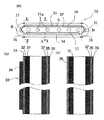
本発明の燃料電池セルを示す図1、図2において、全体として30で示す燃料電池セルは中空平板状であり、断面が扁平状で、全体的に見て細長基板状の導電性の支持基板31を備えている。支持基板31の内部には、適当な間隔で複数の燃料ガス通路31a(ガス流路を形成する)が長さ方向(軸長方向)に貫通して形成されており、燃料電池セル30は、この支持基板31上に各種の部材が設けられた構造を有している。このような燃料電池セル30の複数を、図3に示すように、集電部材40により互いに直列に接続することにより、燃料電池を構成するセルスタックを形成することができる。
1 and 2 showing the fuel battery cell of the present invention, the fuel battery cell indicated by 30 as a whole has a hollow flat plate shape, a flat cross section, and a conductive support substrate having an elongated substrate shape as a whole. 31 is provided. Inside the
支持基板31は、図1、2に示されている形状から理解されるように、平坦部Aと平坦部Aの両端の弧状部Bとからなっており、平坦部Aは主面を構成する。平坦部Aの両主面は互いにほぼ平行に形成されており、平坦部Aの一方の主面と両側の弧状部Bを覆うように燃料極層32が設けられており、さらに、この燃料極層32を覆うように、緻密質な固体電解質層33が積層されており、この固体電解質層33の上には、燃料極層32と対面するように、平坦部Aの一方の主面に酸素極層34が積層されている。燃料極層32及び固体電解質層33は、平坦部Aの一方の主面に、ガス流路形成方向に連続して形成されている。いわゆる縦縞型の燃料電池セルである。
As can be understood from the shape shown in FIGS. 1 and 2, the
燃料電池セル30は、支持基板31が導電性を有するとともに、該導電性支持基板31の一方側主面を構成する平坦部Aに燃料極層32を介して固体電解質層33を形成することにより、ガス透過性が要求される支持基板31、及びガスとの反応性が要求される電極層を、別個に形成するため、それぞれの機能に対応した材料、組織等とすることができ、また集電も容易に行うことができ、最適な燃料電池セルを作製できる。本発明との絡みで説明することが最も良い。
In the
また、燃料極層32及び固体電極層33が積層されていない、支持基板31の他方側主面を構成する平坦部Aには、インターコネクタ35が形成されている。図1から明らかな通り、燃料極層32及び固体電解質層33は、インターコネクタ35の両サイドにまで延びており、支持基板31の表面が外部に露出しないように構成されている。
In addition, an
そして、本発明では、図1(a)(c)、図4(b)に示すように、支持基板31の一方側主面(酸素極層34が形成された側の面)に、酸素極層34の両側に、酸素極層34と所定間隔を置いて離間してインターコネクタ材料層36が形成されており、これらのインターコネクタ材料層36は一定幅を有する直線状とされ、ガス流路形成方向に、かつインターコネクタ35と支持基板31を介して対向するように連続して形成されている。インターコネクタ材料層36は、燃料極層32、固体電解質層33から露出している。
In the present invention, as shown in FIGS. 1 (a), 1 (c), and 4 (b), an oxygen electrode is formed on one main surface of the support substrate 31 (the surface on which the
このような燃料電池セルでは、インターコネクタ35と対向して2条のインターコネクタ材料層36が形成されているため、支持基板31の両側に形成されたインターコネクタ35、インターコネクタ材料層36がそれぞれ長さ方向、幅方向に寸法変化が発生しても、それぞれの寸法変化が打ち消しあって燃料電池セル全体としての長さ方向、幅方向の反り量を抑制できる。特に酸素極層34の両側に所定間隔をおいて2条のインターコネクタ材料層36が形成されているため、図4(c)に示すように、1条のインターコネクタ材料層36を有する場合よりも燃料電池セルの幅方向の反り量を大きく低減できるとともに、反り量低減効果を幅方向両側で均一とできる。尚、図4(b)(c)に示す場合には、長さ方向の寸法変化を抑制することができる。また、インターコネクタ材料層36が長さ方向に連続して形成されているため、長さ方向の反り量を低減できる。さらに、燃料電池セルの製造時においても、熱膨張による変形を低減することができる。
In such a fuel cell, since two interconnector material layers 36 are formed facing the
これらのインターコネクタ材料層36は、インターコネクタ35の厚みよりも厚いことが望ましい。インターコネクタ材料層36は、インターコネクタ35の形成面積よりも小さくなる傾向にあるが、インターコネクタ材料層36の厚みをインターコネクタ35よりも厚くすることにより、支持基板31の両側で還元雰囲気に晒されることにより発生する反り量を近づけることができ、反り量をさらに低減できるとともに、インターコネクタ材料層36の形成面積を小さくできる一方で、酸素極層34の形成面積を大きくすることができる。インターコネクタ35の厚みは100μm以下、特には70μm以下であることが望ましい。
These interconnector material layers 36 are preferably thicker than the
また、図4(d)に示すように、酸素極層34をセル長さ方向に複数に分割し、これらの分割酸素極層34aの間に、該分割酸素極層34と離間してインターコネクタ材料層36をセル幅方向に直線状に設けることができる。この場合には、セル幅方向の寸法変化を十分に抑制することができる。
Further, as shown in FIG. 4D, the
また、図4(e)に示すように、酸素極層34をセル長さ方向に複数に分割するとともに、幅方向及び長さ方向に複数に分割し、これらの分割酸素極層34aを取り囲むように、分割酸素極層34aとは離間してインターコネクタ材料層36を格子状に設けることができる。この場合には、セル幅方向及び長さ方向の寸法変化を十分に抑制することができる。
Further, as shown in FIG. 4 (e), the
また、図4(f)に示すように、酸素極層34の燃料ガス出口側に、酸素極層34と離間してインターコネクタ材料層36をセル幅方向に設けることができる。これにより、燃料ガス出口側におけるセル幅方向の寸法変化を抑制することができるとともに、インターコネクタ材料層36により、セルの燃料ガス出口側端の強度が向上し、端部の破損を抑制できる。
Further, as shown in FIG. 4 (f), an
インターコネクタ材料層36は、図2(b)に示すように、絶縁層33aにより被覆されていることが望ましい。これにより酸素極層34との導通や、他部材、例えば集電部材との導通を防止でき、燃料電池セルの信頼性を向上できる。図2(b)では、固体電解質層33の開口部の燃料極32上に、固体電解質層33の厚みよりも厚いインターコネクタ材料層36が形成され、このインターコネクタ材料層36は絶縁層33aにより被覆されている。
The
尚、図2(a)に示すように、支持基板31に直接インターコネクタ材料層36を設け、このインターコネクタ材料層36を絶縁層33aにより被覆しても良いことは勿論である。この場合、インターコネクタ35と異なり、インターコネクタ材料層36が支持基板31に直接形成されているため、より反り量を抑制できる。また、インターコネクタ材料層36を薄くし、インターコネクタ材料層36上の絶縁層33aの露出面を固体電解質層33の露出面とほぼ同一面とすることにより、凹凸を無くすこともできる。
Of course, as shown in FIG. 2A, an
このようにインターコネクタ材料層36を絶縁層33aにより被覆することにより、インターコネクタ材料層36の厚みを自由に制御できるとともに、絶縁層33aとして最適な材料を選択できる。絶縁層33aは、ガス封止性の点からはガラスからなることが望ましい。
By covering the
また、本発明の燃料電池セルでは、長さが120mm以上、厚みが8mm以下、幅が20mm以上である場合に好適に用いることができる。即ち、中空平板型燃料電池セルでは、長さが長い場合、図4(a−1)に示すように、セルを長さ方向に見た場合に、インターコネクタ側を背にして弓なりに反り易くなるため(a−2)、本発明を有効に用いることができ、また、幅が広くなると、セルの幅方向に、即ち、燃料電池セルを幅方向に見た場合に、インターコネクタ側を背にして三日月状に反り易くなるため(a−3)、本発明を有効に用いることができる。セルの長さは120mm以上、特に145mm以上である場合に、好適に用いることができる。 The fuel cell of the present invention can be suitably used when the length is 120 mm or more, the thickness is 8 mm or less, and the width is 20 mm or more. That is, in a hollow flat plate type fuel cell, when the length is long, as shown in FIG. 4 (a-1), when the cell is viewed in the length direction, it is easy to warp like a bow with the interconnector side as the back. Therefore, (a-2) the present invention can be used effectively, and when the width is increased, the interconnector side is placed in the back direction when the fuel cell is viewed in the width direction. Therefore, the present invention can be effectively used because it tends to warp in a crescent shape (a-3). When the length of the cell is 120 mm or more, particularly 145 mm or more, it can be suitably used.
また、燃料電池セルの厚みが8mm以下である場合には、対向する主面間の距離が薄いため、長さ方向や幅方向に反り易くなるため、本発明を有効に用いることができる。特に3mm以下である場合に好適に用いることができる。 In addition, when the thickness of the fuel cell is 8 mm or less, the distance between the main surfaces facing each other is small, so that the fuel cell tends to warp in the length direction and the width direction, so that the present invention can be used effectively. In particular, it can be suitably used when it is 3 mm or less.
上記のような構造の燃料電池セルでは、燃料極層32の酸素極34と対面している部分が燃料極として作動して発電する。即ち、酸素極層34の外側に空気等の酸素含有ガスを流し、且つ支持基板31内のガス通路31aに燃料ガス(水素)を流し、所定の作動温度まで加熱することにより、酸素極層34で下記式(1)の電極反応を生じ、また燃料極層32の燃料極となる部分では例えば下記式(2)の電極反応を生じることによって発電する。
In the fuel cell having the above structure, the portion of the
酸素極: 1/2O2+2e− → O2− (固体電解質) …(1)
燃料極: O2− (固体電解質)+ H2 → H2O+2e− …(2)
かかる発電によって生成した電流は、支持基板31に取り付けられているインターコネクタ35を介して集電される。
Oxygen electrode: 1 / 2O 2 + 2e − → O 2− (solid electrolyte) (1)
Fuel electrode: O 2− (solid electrolyte) + H 2 → H 2 O + 2e − (2)
The current generated by the power generation is collected through the
(支持基板31)
上記のような構造を有する燃料電池セル30において、支持基板31は、燃料ガスを燃料極層32まで透過させるためにガス透過性であること、及びインターコネクタ35を介しての集電を行うために導電性であること、同時焼成時の熱膨張差による固体電解質などのクラックや剥離がないことが要求されるが、このような要求を満たすと同時に、還元・酸化サイクルにおける支持基板31の体積膨張に起因した固体電解質などのクラックを抑制する目的で、触媒活性金属及びその酸化物のいずれかと、触媒金属及びその酸化物との反応物を生成しない無機骨材、例えば、金属酸化物である固体電解質層又は少なくとも一種の希土類元素を含有する希土類元素酸化物とを含有せしめて構成する。
(Support substrate 31)
In the
触媒金属としてはFe、Co、Niなどの鉄族成分があり、金属単体であってもよいし、また酸化物、合金もしくは合金酸化物であってもよい。本発明では、何れをも使用することができるが、安価であること及び燃料ガス中で安定であることからNi及び/またはNiOを含有していることが好ましい。 As the catalyst metal, there are iron group components such as Fe, Co, and Ni, which may be a single metal, or an oxide, an alloy, or an alloy oxide. In the present invention, any of them can be used, but it is preferable that Ni and / or NiO are contained because they are inexpensive and stable in fuel gas.
また、無機骨材としては、(2)の電極反応を促進するために、所謂三相界面(電解質/触媒金属/気相の界面)を増やすために、固体電解質層33を形成している安定化ジルコニアやランタンガレート系ペロブスカイト型組成物等と同等の材料を用いても良いし、熱膨張係数を下げて固体電解質層33と近似させるために希土類酸化物を用いても良い。後者には特にSc,Y,Lu,Yb,Tm,Er,Ho,Dy,Gd,Sm,Prからなる群より選ばれた少なくとも1種の希土類元素を含む酸化物が使用される。このような希土類酸化物の具体例としては、Sc2O3、Y2O3、Lu2O3、Yb2O3、Tm2O3、Er2O3、Ho2O3、Dy2O3、Gd2O3、Sm2O3、Pr2O3を例示することができ、特に安価であるという点で、Y2O3,Yb2O3、さらにはY2O3が好適である。
Further, as the inorganic aggregate, the
尚、支持基板31中には、要求される特性が損なわれない限りの範囲で他の金属成分や酸化物成分を含有していてもよい。
The
上記のような支持基板31は、燃料ガス透過性を有していることが必要であるため、通常、開気孔率が30%以上、特に35〜50%の範囲にあることが好適である。また、支持基板31の導電率は、300S/cm以上、特に440S/cm以上であることが好ましい。
Since the
また、支持基板31の平坦部Aの長さは、通常、20〜35mm、弧状部Bの長さ(弧の長さ)は、3〜8mm程度であり、支持基板31の厚みは(平坦部Aの両面の間隔)は2.5〜8mm程度であることが望ましい。
Further, the length of the flat portion A of the
(燃料極層32)
本発明において、燃料極層32は、前述した式(2)の電極反応を生じせしめるものであり、それ自体公知の多孔質の導電性セラミックスから形成される。例えば、希土類元素が固溶しているZrO2と、Ni及び/またはNiOとから形成される。この希土類元素が固溶しているZrO2(安定化ジルコニア)としては、以下に述べる固体電解質層33の形成に使用されているものと同様のものを用いるのがよい。
(Fuel electrode layer 32)
In the present invention, the
燃料極層32中の安定化ジルコニア含量は、35〜65体積%の範囲にあるのが好ましく、またNi或いはNiO含量は、65〜35体積%であるのがよい。さらに、この燃料極層32の開気孔率は、15%以上、特に20〜40%の範囲にあるのがよく、その厚みは、1〜30μmであることが望ましい。例えば、燃料極層32の厚みがあまり薄いと、性能が低下するおそれがあり、またあまり厚いと、固体電解質層33と燃料極層32との間で熱膨張差による剥離等を生じるおそれがある。
The stabilized zirconia content in the
また、図1の例では、この燃料極層32は、インターコネクタ35の両サイドにまで延びているが、酸素極層34に対面する位置に存在して燃料極層が形成されていればよいため、例えば酸素極層34が設けられている側の平坦部Aにのみ燃料極層32が形成されていてもよい。さらには、支持基板31の全周にわたって燃料極層32を形成することも可能である。本発明においては、固体電解質層33と支持基板31との接合強度を高めるために、固体電解質層33の全体が燃料極層32上に形成されていることが好適である。
Further, in the example of FIG. 1, the
(固体電解質層33)
この燃料極層32上に設けられている固体電解質層33は、一般に3〜15モル%の希土類元素が固溶したZrO2(通常、安定化ジルコニア)と呼ばれる緻密質なセラミックスから形成されている。希土類元素としては、Sc,Y,La,Ce,Pr,Nd,Pm,Sm,Eu,Gd,Tb,Dy,Ho,Er,Tm,Yb,Luを例示することができるが、安価であるという点からY、Ybが望ましい。
(Solid electrolyte layer 33)
The
この固体電解質層33を形成する安定化ジルコニアセラミックスは、ガス透過を防止するという点から、相対密度(アルキメデス法による)が93%以上、特に95%以上の緻密質であることが望ましく、且つその厚みが10〜100μmであることが望ましい。固体電解質層3としては、安定化ジルコニア以外に、ランタンガレート系ペロブスカイト型組成物から構成されていても良い。
The stabilized zirconia ceramics forming the
(酸素極層34)
酸素極層34は、所謂ABO3型のペロブスカイト型酸化物からなる導電性セラミックスから形成される。かかるペロブスカイト型酸化物としては、遷移金属ペロブスカイト型酸化物、特にAサイトにLaを有するLaMnO3系酸化物、LaFeO3系酸化物、LaCoO3系酸化物の少なくとも1種が好適であり、600〜1000℃程度の作動温度での電気伝導性が高いという点からLaFeO3系酸化物が特に好適である。尚、上記ペロブスカイト型酸化物においては、AサイトにLaと共にSrなどが存在していてもよいし、さらにBサイトには、FeとともにCoやMnが存在していてもよい。
(Oxygen electrode layer 34)
The
また、酸素極層34は、ガス透過性を有していなければならず、従って、酸素極層34を形成する導電性セラミックス(ペロブスカイト型酸化物)は、開気孔率が20%以上、特に30〜50%の範囲にあることが望ましい。
The
このような酸素極層34の厚みは、集電性という点から30〜100μmであることが望ましい。
The thickness of the
(インターコネクタ35)
上記の酸素極層34に対面する位置において、支持基板31上に設けられているインターコネクタ35は、導電性セラミックスからなるが、燃料ガス(水素)及び酸素含有ガスと接触するため、耐還元性、耐酸化性を有していることが必要である。このため、かかる導電性セラミックスとしては、一般に、ランタンクロマイト系のペロブスカイト型酸化物(LaCrO3系酸化物)を使用できる。ランタンクロマイト系酸化物としては、(La,Sr)CrO3、Laの一部をSrで置換したもの、Crの一部をMgで置換したもの、La(Cr,Mg)O3を使用できる。
(Interconnector 35)
The
また、支持基板31の内部を通る燃料ガス及び支持基板31の外部を通る酸素含有ガスのリークを防止するため、かかる導電性セラミックスは緻密質でなければならず、例えば93%以上、特に95%以上の相対密度を有していることが好適である。
Further, in order to prevent leakage of the fuel gas passing through the inside of the
かかるインターコネクタ35は、ガスのリーク防止と電気抵抗という点から、10〜200μmであることが望ましい。即ち、この範囲よりも厚みが薄いと、ガスのリークを生じやすく、またこの範囲よりも厚みが大きいと、電気抵抗が大きく、電位降下により集電機能が低下してしまうおそれがあるからである。
The
また、図1から明らかな通り、ガスのリークを防止するために、インターコネクタ35の両サイドには、緻密質の固体電解質層33が密着しているが、シール性を高めるために、例えばY2O3などからなる接合層(図示せず)をインターコネクタ35の両側面と固体電解質層33との間に設けることもできる。
Further, as is clear from FIG. 1, in order to prevent gas leakage, a dense
インターコネクタ材料層36は、インターコネクタ35と同一材料を用いることができるが、この場合には製造上容易となる。また、インターコネクタ35の材料と少々異なっていても良い。例えば、置換材料が異なっていたり、添加物が異なるものも使用できる。
The
インターコネクタ35の外面(上面)には、P型半導体層39が設けられている。即ち、この燃料電池セルから組み立てられるセルスタック(図3参照)では、インターコネクタ35には、導電性の集電部材40が接続されるが、集電部材40を直接インターコネクタ35に直接接続すると、非オーム接触により、電位降下が大きくなってしまい、集電性能が低下してしまう。
A P-
しかるに、集電部材40を、P型半導体層39を介してインターコネクタ35に接続させることにより、両者の接触がオーム接触となり、電位降下を少なくし、集電性能の低下を有効に回避することが可能となり、例えば、一方の燃料電池セル30の酸素極層34からの電流を、他方の燃料電池セル30の支持基板31に効率良く伝達できる。このようなP型半導体としては、遷移金属ペロブスカイト型酸化物を例示することができる。
However, by connecting the current collecting
具体的には、インターコネクタ35を構成するLaCrO3系酸化物よりも電子伝導性が大きいもの、例えば、BサイトにMn、Fe、Coなどが存在するLaMnO3系酸化物、LaFeO3系酸化物、LaCoO3系酸化物などの少なくとも一種からなるP型半導体セラミックスを使用することができる。このようなP型半導体層39の厚みは、一般に、30〜100μmの範囲にあることが好ましい。
Specifically, those having higher electronic conductivity than LaCrO 3 oxides constituting the
また、インターコネクタ35は、固体電解質層33が設けられていない側の支持基板31の平坦部分A上に直接設けることもできるが、この部分にも燃料極材料が設けられ、この燃料極材料層37上にインターコネクタ35が設けられている。即ち、燃料極材料を支持基板31の全周にわたって設け、燃料極材料層37上にインターコネクタ35を設けられており、この場合には、支持基板31とインターコネクタ35との間の界面での電位降下を抑制することができる上で有利である。
The
(燃料電池セルの製造)
以上のような構造を有する燃料電池セルは、以下のようにして製造される。先ず、Ni等の鉄族金属或いはその酸化物粉末と、例えばY2O3粉末と、有機バインダーと、溶媒とを混合して坏土を調製し、この坏土を用いての押出成形により、支持基板成形体を作製し、これを乾燥する。
(Manufacture of fuel cells)
The fuel battery cell having the above structure is manufactured as follows. First, an iron group metal such as Ni or its oxide powder, for example, Y 2 O 3 powder, an organic binder, and a solvent are mixed to prepare a clay, and by extrusion molding using this clay, A support substrate molding is produced and dried.
次に、燃料極層形成用材料(Ni或いはNiO粉末と安定化ジルコニア粉末)、有機バインダー及び溶媒を混合してスラリーを調製し、このスラリーを用いて燃料極層用のシートを作製する。また、燃料極層用のシートを作製する代りに、燃料極層形成用材料を溶媒中に分散したペーストを、上記で形成された支持基板成形体の所定位置に塗布し乾燥して、燃料極層用のコーティング層を形成してもよい。この際、インタコネクタ材料層が形成される部分には燃料極層が形成されないようにした。これを仮焼し、表面に燃料極層仮焼体が形成された支持基板仮焼体を作製し、インターコネクタが形成される部分、及び燃料極層仮焼体の開口部にマスクして、固体電解質層が形成されないようにする。 Next, a fuel electrode layer forming material (Ni or NiO powder and stabilized zirconia powder), an organic binder, and a solvent are mixed to prepare a slurry, and a sheet for the fuel electrode layer is prepared using this slurry. Further, instead of producing a sheet for the fuel electrode layer, a paste in which the material for forming the fuel electrode layer is dispersed in a solvent is applied to a predetermined position of the formed support substrate and dried, and then the fuel electrode layer is formed. A coating layer for the layer may be formed. At this time, the fuel electrode layer was not formed in the portion where the interconnector material layer was formed. This is calcined to produce a support substrate calcined body having a fuel electrode layer calcined body formed on the surface, masking the portion where the interconnector is formed, and the opening of the fuel electrode layer calcined body, A solid electrolyte layer is prevented from being formed.
この後、固体電解質材料を含有する浸漬液を作製し、この浸漬液に上記支持基板仮焼体を浸漬する。固体電解質材料としては、例えば希土類元素が固溶したZrO2粉を用い、その他に、浸漬液中には、有機バインダーと、溶媒が添加混合されている。この浸漬液は、所定の粘度を有するように、有機成分が調整されている。 Thereafter, an immersion liquid containing a solid electrolyte material is prepared, and the support substrate calcined body is immersed in the immersion liquid. As the solid electrolyte material, for example, ZrO 2 powder in which a rare earth element is dissolved is used. In addition, an organic binder and a solvent are added and mixed in the immersion liquid. The immersion liquid has an organic component adjusted so as to have a predetermined viscosity.
この後、インターコネクタ用材料(例えば、LaCrO3系酸化物粉末)、有機バインダー及び溶媒を混合してスラリーを調製し、インターコネクタ用シート及びインターコネクタ材料層用シートを作製する。これらのシートを、上記で得られた積層体のマスクした所定位置に、マスクを除去して積層し、焼成用積層体を作製する。 Thereafter, a material for an interconnector (for example, LaCrO 3 oxide powder), an organic binder and a solvent are mixed to prepare a slurry, and an interconnector sheet and an interconnector material layer sheet are prepared. These sheets are laminated by removing the mask at the masked predetermined position of the laminate obtained above to produce a laminate for firing.
次いで、上記の焼成用積層体を脱バインダ処理し、酸素含有雰囲気中、1300〜1600℃で同時焼成し、得られた焼結体の所定の位置に、酸素極層形成用材料(例えば、LaFeO3系酸化物粉末)と溶媒を含有するペースト、及び必要により、P型半導体層形成用材料(例えば、LaFeO3系酸化物粉末)と溶媒を含むペーストを、ディッピング等により塗布し、1000〜1300℃で焼き付けることにより、図1に示す構造の本発明の燃料電池セル30を製造することができる。
Next, the above laminate for firing is subjected to binder removal treatment, and co-fired at 1300 to 1600 ° C. in an oxygen-containing atmosphere, and an oxygen electrode layer forming material (for example, LaFeO) is placed at a predetermined position of the obtained sintered body. 3 type oxide powder) and a paste containing a solvent, and if necessary, a paste containing a P-type semiconductor layer forming material (for example, LaFeO 3 type oxide powder) and a solvent is applied by dipping or the like, and 1000-1300 By baking at a temperature of 0 ° C., the
尚、支持基板31や燃料極層32の形成にNi単体を用いた場合には、酸素含有雰囲気での焼成により、Niが酸化されてNiOとなっているが、必要により、還元処理することにより、Niに戻すことができる。
In the case where Ni alone is used to form the
(セルスタック)
セルスタックは、図3に示すように、上述した燃料電池セル30が複数集合して、上下に隣接する一方の燃料電池セル30と他方の燃料電池セル30との間に、金属フェルト及び/又は金属板からなる集電部材40を介在させ、両者を互いに直列に接続することにより構成されている。即ち、一方の燃料電池セル30の支持基板31は、インターコネクタ35、P型半導体層39、集電部材40を介して、他方の燃料電池セル30の酸素極層34に電気的に接続されている。また、このようなセルスタックは、図3に示すように、サイドバイサイドに配置されており、隣接するセルスタック同士は、導電部材42によって直列に接続されている。尚、図3では、燃料電池セルは簡略化して記載している。
(Cell stack)
As shown in FIG. 3, the cell stack includes a plurality of the
本発明の燃料電池は、図3のセルスタックを、収納容器内に収容して構成される。この収納容器には、外部から水素等の燃料ガスを燃料電池セル30に導入する導入管、及び空気等の酸素含有ガスを燃料電池セル30の外部空間に導入するための導入管が設けられており、燃料電池セルが所定温度(例えば、600〜900℃)に加熱されることにより発電し、使用された燃料ガス、酸素含有ガスは、収納容器外に排出される。
The fuel cell of the present invention is configured by accommodating the cell stack of FIG. 3 in a storage container. The storage container is provided with an introduction pipe for introducing a fuel gas such as hydrogen into the
尚、本発明は上記形態に限定されるものではなく、発明の要旨を変更しない範囲で種々の変更が可能である。例えば、上記形態では、支持基板31上に燃料極層32を形成した場合について説明したが、支持基板自体に燃料極としての機能を付与し、支持基板に固体電解質層、酸素極層を形成しても良い。また、上記形態では、支持基板31上に燃料極層32を形成した場合について説明したが、支持基板に酸素極層を形成したセルであってもよい。さらに、支持基板自体に酸素極層としての機能を付与しても良い。
In addition, this invention is not limited to the said form, A various change is possible in the range which does not change the summary of invention. For example, in the above embodiment, the case where the
平均粒径0.5μmのNiO粉末と、Y2O3粉末(平均粒径は0.6〜0.9μm)を、焼成後におけるNiOがNi換算で48体積%、Y2O3が52体積%になるようにして混合し、この混合粉末に、ポアー剤、有機バインダーと、水とを混合して形成した支持基板用坏土を押出成形し、これを乾燥し、脱バインダー処理し、扁平状の支持基板用成形体を作製し、これを乾燥した。この後、1000℃で仮焼し、支持基板仮焼体を作製した。 NiO powder having an average particle size of 0.5 μm and Y 2 O 3 powder (average particle size is 0.6 to 0.9 μm), after firing, NiO is 48 vol% in terms of Ni, and Y 2 O 3 is 52 vol. The resulting mixed powder is extruded with a support substrate clay formed by mixing a pore agent, an organic binder, and water, dried, debindered, and flattened. A shaped support substrate shaped body was prepared and dried. Then, it calcined at 1000 degreeC and produced the support substrate calcined body.
次に、8モル%Y2O3を含有するZrO2(YSZ)粉末と、NiO粉末と、有機バインダーと、溶媒とを混合したスラリーを用いて燃料極層形成用シートを作製し、これを支持基板仮焼体の所定位置に積層し、1000℃で仮焼し、支持基板仮焼体の表面に燃料側電極仮焼体を形成した。尚、燃料極層形成用シートとして、インターコネクタ材料層を形成する位置に開口したシートを用いた。 Next, a fuel electrode layer forming sheet was prepared using a slurry obtained by mixing ZrO 2 (YSZ) powder containing 8 mol% Y 2 O 3 , NiO powder, an organic binder, and a solvent. It laminated | stacked on the predetermined position of the support substrate calcined body, and calcined at 1000 degreeC, and formed the fuel side electrode calcined body on the surface of the support substrate calcined body. In addition, the sheet | seat opened in the position which forms an interconnector material layer was used as a sheet | seat for fuel electrode layer forming.
この後、図2(a)、図4(b)のインターコネクタ材料層を形成する位置、及びインターコネクタ形成位置にマスクした。 Thereafter, masking was performed at the position where the interconnector material layer shown in FIGS. 2A and 4B was formed and the position where the interconnector was formed.
一方、上記YSZ粉末と、有機バインダーと、溶媒とを混合した浸漬液を作製し、この浸漬液中に支持基板仮焼体を浸漬し、引き上げることにより燃料側電極仮焼体の表面に固体電解質材料の塗布膜を形成し、乾燥することにより固体電解質層成形体を形成した。 On the other hand, an immersion liquid in which the YSZ powder, an organic binder, and a solvent are mixed is prepared, and the support substrate calcined body is immersed in the immersion liquid, and then pulled up to form a solid electrolyte on the surface of the fuel-side electrode calcined body. A coating film of the material was formed and dried to form a solid electrolyte layer molded body.
次に、平均粒径2μmのLaCrO3系酸化物粉末と、有機バインダーと、溶媒とを混合したスラリーを用いて、インターコネクタ用シート、及びインターコネクタ材料層用シートを作製し、これらのシートを、上記マスクを剥離して露出した部分に積層し、図2(b)に示すように、インターコネクタ材料層用シート表面及びその近傍にガラスペーストを塗布し、支持基板仮焼体、燃料極層仮焼体、インターコネクタ用シート、及びインターコネクタ材料層用シート、固体電解質層成形体からなる焼結用積層シートを作製した。次に、この焼結用積層シートを脱バインダ処理し、大気中にて1500℃で同時焼成した。 Next, an interconnector sheet and an interconnector material layer sheet are prepared using a slurry obtained by mixing LaCrO 3 oxide powder having an average particle diameter of 2 μm, an organic binder, and a solvent. The mask is peeled and laminated on the exposed portion, and as shown in FIG. 2B, a glass paste is applied to the surface of the interconnector material layer sheet and its vicinity, and the support substrate calcined body, fuel electrode layer A laminated sheet for sintering composed of a calcined body, an interconnector sheet, an interconnector material layer sheet, and a solid electrolyte layer molded body was produced. Next, the laminated sheet for sintering was subjected to binder removal treatment, and co-fired at 1500 ° C. in the air.
得られた焼結体を、平均粒径2μmのLa0.6Sr0.4Co0.2Fe0.8O3粉末と、溶媒をからなるペースト中に浸漬し、焼結体に形成されている固体電解質層の表面に酸素極層用コーティング層を設け、同時に、上記ペーストを焼結体に形成されているインターコネクタの外面に塗布し、P型半導体用コーティング層を設け、さらに、1150℃で焼き付け、燃料電池セルを作製した。 The obtained sintered body is immersed in a paste made of La 0.6 Sr 0.4 Co 0.2 Fe 0.8 O 3 powder having an average particle diameter of 2 μm and a solvent, and formed into a sintered body. A coating layer for the oxygen electrode layer is provided on the surface of the solid electrolyte layer, and at the same time, the paste is applied to the outer surface of the interconnector formed in the sintered body, and a coating layer for P-type semiconductor is provided. Baking was performed at 0 ° C. to produce a fuel cell.
作製した燃料電池セルの長さは145mm、幅は26mm、厚みは3.2mm、燃料極層の厚みは10μm、酸素極層の厚みは50μm、インターコネクタの厚みは50μm、インターコネクタ材料層の厚みは70μm、P型半導体層の厚みは50μmであった。インターコネクタ材料層の幅は5mmであった。 The produced fuel cell has a length of 145 mm, a width of 26 mm, a thickness of 3.2 mm, a fuel electrode layer thickness of 10 μm, an oxygen electrode layer thickness of 50 μm, an interconnector thickness of 50 μm, and an interconnector material layer thickness. Was 70 μm, and the thickness of the P-type semiconductor layer was 50 μm. The width of the interconnector material layer was 5 mm.
作製した燃料電池セルについて、図4(a)に示すように、インタコネクタの形成側と反対側の面の上下端に直線状の定規を当て、この定規とセル表面との最大距離Lhを求め、長さ方向の反り量とし、インタコネクタの形成側と反対側の面の幅方向両端に直線状の定規を当て、この定規とセル表面との最大距離Lbを求め、幅方向の反り量とした。この結果、長さ方向の反り量は0.15mm、幅方向の反り量は0.07mmであった。 For the manufactured fuel cell, as shown in FIG. 4A, a linear ruler is applied to the upper and lower ends of the surface opposite to the interconnector forming side, and the maximum distance Lh between the ruler and the cell surface is obtained. The amount of warpage in the length direction is determined by applying a linear ruler to both ends in the width direction of the surface opposite to the interconnector forming side to obtain the maximum distance Lb between the ruler and the cell surface. did. As a result, the warpage amount in the length direction was 0.15 mm, and the warpage amount in the width direction was 0.07 mm.
さらに、得られた燃料電池セルを850℃の温度で水素ガスをガス通路31a内に12時間供給し、水素ガスを流しながら放冷した。その後、上記と同様にして長さ方向の反り量及び幅方向の反り量を求めたところ、長さ方向の反り量は0.4mm、幅方向の反り量は0.15mmであった。
Furthermore, hydrogen gas was supplied into the
一方、インターコネクタ材料層を形成しない以外は、上記と同様にして比較例の燃料電池セルを作製し、作製後の反り量、及び上記還元処理後の反り量を測定したところ、焼成後においては、長さ方向の反り量は0.5mm、幅方向の反り量は0.3mmであり、還元処理後では、長さ方向の反り量は1.8mm、幅方向の反り量は0.6mmであった。従って、本発明の燃料電池セルでは、反り量を抑制できることがわかる。 On the other hand, except that no interconnector material layer was formed, a fuel cell of a comparative example was produced in the same manner as described above, and the amount of warpage after production and the amount of warpage after the reduction treatment were measured. The warping amount in the length direction is 0.5 mm, the warping amount in the width direction is 0.3 mm, and after the reduction treatment, the warping amount in the length direction is 1.8 mm, and the warping amount in the width direction is 0.6 mm. there were. Therefore, it can be seen that the amount of warpage can be suppressed in the fuel battery cell of the present invention.
31・・・支持基板(支持体)
31a・・・燃料ガス通路
32・・・燃料極層
33・・・固体電解質層
34・・・酸素極層
35・・・インターコネクタ
36・・・インターコネクタ材料層
40・・・集電部材
31 ... Support substrate (support)
31a ...
Claims (12)
Priority Applications (1)
| Application Number | Priority Date | Filing Date | Title |
|---|---|---|---|
| JP2004340341A JP4925574B2 (en) | 2004-11-25 | 2004-11-25 | Fuel cell and fuel cell |
Applications Claiming Priority (1)
| Application Number | Priority Date | Filing Date | Title |
|---|---|---|---|
| JP2004340341A JP4925574B2 (en) | 2004-11-25 | 2004-11-25 | Fuel cell and fuel cell |
Publications (2)
| Publication Number | Publication Date |
|---|---|
| JP2006155919A JP2006155919A (en) | 2006-06-15 |
| JP4925574B2 true JP4925574B2 (en) | 2012-04-25 |
Family
ID=36633975
Family Applications (1)
| Application Number | Title | Priority Date | Filing Date |
|---|---|---|---|
| JP2004340341A Expired - Fee Related JP4925574B2 (en) | 2004-11-25 | 2004-11-25 | Fuel cell and fuel cell |
Country Status (1)
| Country | Link |
|---|---|
| JP (1) | JP4925574B2 (en) |
Families Citing this family (5)
| Publication number | Priority date | Publication date | Assignee | Title |
|---|---|---|---|---|
| JP4942335B2 (en) * | 2005-11-30 | 2012-05-30 | 京セラ株式会社 | Fuel cell stack and fuel cell |
| JP2010516035A (en) * | 2007-01-12 | 2010-05-13 | 本田技研工業株式会社 | Structure of cathode for solid oxide fuel cell |
| JP5188069B2 (en) * | 2007-01-29 | 2013-04-24 | 京セラ株式会社 | Fuel cell and cell stack and fuel cell |
| JP4942852B2 (en) * | 2011-10-24 | 2012-05-30 | 京セラ株式会社 | Fuel cell stack and fuel cell |
| JP6139344B2 (en) * | 2013-09-06 | 2017-05-31 | 株式会社東芝 | Electrochemical cell |
Family Cites Families (4)
| Publication number | Priority date | Publication date | Assignee | Title |
|---|---|---|---|---|
| JPH10134828A (en) * | 1996-10-30 | 1998-05-22 | Tokyo Gas Co Ltd | Current collecting method between fuel electrode and separator of flat solid electrolyte fuel cell |
| JPH1116585A (en) * | 1997-06-26 | 1999-01-22 | Tokyo Gas Co Ltd | Flat solid electrolyte fuel cell and its layering method |
| JP4028809B2 (en) * | 2003-02-20 | 2007-12-26 | 京セラ株式会社 | Fuel cell and fuel cell |
| JP4192017B2 (en) * | 2003-03-12 | 2008-12-03 | 京セラ株式会社 | Cell stack and fuel cell |
-
2004
- 2004-11-25 JP JP2004340341A patent/JP4925574B2/en not_active Expired - Fee Related
Also Published As
| Publication number | Publication date |
|---|---|
| JP2006155919A (en) | 2006-06-15 |
Similar Documents
| Publication | Publication Date | Title |
|---|---|---|
| JP3996861B2 (en) | Fuel cell and fuel cell | |
| JP5175527B2 (en) | Cell stack and fuel cell | |
| JP5175461B2 (en) | Horizontally-striped fuel cell and fuel cell | |
| JP5118865B2 (en) | Horizontally-striped fuel cell and method for producing the same | |
| JP5188069B2 (en) | Fuel cell and cell stack and fuel cell | |
| JP5079991B2 (en) | Fuel cell and fuel cell | |
| JP4931365B2 (en) | Support substrate for fuel cell, fuel cell, and fuel cell | |
| JP4545014B2 (en) | FUEL BATTERY CELL, FUEL BATTERY CELL STACK USING THE SAME, FUEL CELL | |
| JP2004265734A (en) | Fuel battery cell | |
| JP5094005B2 (en) | Fuel cell, cell stack and fuel cell | |
| JP4798947B2 (en) | Fuel cell, cell stack and fuel cell | |
| JP4350403B2 (en) | Solid oxide fuel cell | |
| JP4883992B2 (en) | Fuel cell and fuel cell | |
| JP2007200761A (en) | Battery cell, cell stack and fuel cell | |
| JP4748971B2 (en) | Fuel cell and fuel cell | |
| JP4593997B2 (en) | Support for fuel cell, fuel cell, and fuel cell | |
| JP4925574B2 (en) | Fuel cell and fuel cell | |
| JP4130135B2 (en) | Surface treatment method for current collecting member | |
| JP5036163B2 (en) | Fuel cell, cell stack and fuel cell | |
| JP4805642B2 (en) | Fuel cell, fuel cell stack and fuel cell | |
| JP2006127973A (en) | Fuel battery cell | |
| JP4480377B2 (en) | Fuel cell and fuel cell | |
| JP4794233B2 (en) | Hollow flat plate fuel cell and fuel cell | |
| JP4646511B2 (en) | Fuel cell, cell stack and fuel cell | |
| JP2005216619A (en) | Fuel battery cell and fuel battery |
Legal Events
| Date | Code | Title | Description |
|---|---|---|---|
| A621 | Written request for application examination |
Free format text: JAPANESE INTERMEDIATE CODE: A621 Effective date: 20070912 |
|
| A977 | Report on retrieval |
Free format text: JAPANESE INTERMEDIATE CODE: A971007 Effective date: 20100709 |
|
| A131 | Notification of reasons for refusal |
Free format text: JAPANESE INTERMEDIATE CODE: A131 Effective date: 20100803 |
|
| A521 | Written amendment |
Free format text: JAPANESE INTERMEDIATE CODE: A523 Effective date: 20100930 |
|
| A131 | Notification of reasons for refusal |
Free format text: JAPANESE INTERMEDIATE CODE: A131 Effective date: 20110517 |
|
| A521 | Written amendment |
Free format text: JAPANESE INTERMEDIATE CODE: A523 Effective date: 20110707 |
|
| TRDD | Decision of grant or rejection written | ||
| A01 | Written decision to grant a patent or to grant a registration (utility model) |
Free format text: JAPANESE INTERMEDIATE CODE: A01 Effective date: 20120110 |
|
| A01 | Written decision to grant a patent or to grant a registration (utility model) |
Free format text: JAPANESE INTERMEDIATE CODE: A01 |
|
| A61 | First payment of annual fees (during grant procedure) |
Free format text: JAPANESE INTERMEDIATE CODE: A61 Effective date: 20120207 |
|
| FPAY | Renewal fee payment (event date is renewal date of database) |
Free format text: PAYMENT UNTIL: 20150217 Year of fee payment: 3 |
|
| R150 | Certificate of patent or registration of utility model |
Free format text: JAPANESE INTERMEDIATE CODE: R150 |
|
| LAPS | Cancellation because of no payment of annual fees |