JP4923201B2 - Bullet ball machine - Google Patents
Bullet ball machine Download PDFInfo
- Publication number
- JP4923201B2 JP4923201B2 JP2006305155A JP2006305155A JP4923201B2 JP 4923201 B2 JP4923201 B2 JP 4923201B2 JP 2006305155 A JP2006305155 A JP 2006305155A JP 2006305155 A JP2006305155 A JP 2006305155A JP 4923201 B2 JP4923201 B2 JP 4923201B2
- Authority
- JP
- Japan
- Prior art keywords
- control device
- floating
- fan
- symbol
- blow
- Prior art date
- Legal status (The legal status is an assumption and is not a legal conclusion. Google has not performed a legal analysis and makes no representation as to the accuracy of the status listed.)
- Expired - Fee Related
Links
Images


Landscapes
- Pinball Game Machines (AREA)
Description
本発明は、抽選結果を遊技者に報知する表示装置の前面にて浮遊物を舞い上がらせることで、抽選結果に期待感を与える遊技機に関するものである。 The present invention relates to a gaming machine that gives a sense of expectation to a lottery result by causing a floating object to rise in front of a display device that informs a player of the lottery result.
従来、弾球遊技機であるパチンコ遊技機は、遊技領域に配置された抽選口(始動口)に発射された遊技球が入球することで乱数値を抽出し、該抽出した乱数値が予め定められた所定の値であるか否かを抽選し、その抽選で当選すると遊技者にとって有利な遊技状態(大当り状態)に移行する構成が一般的である。
なお、遊技者にとって有利な遊技状態に移行するか否かの抽選は、遊技機全体の制御を司る主制御装置で行なわれる。また、パチンコ遊技機には、主制御装置以外に賞球の払出しを制御する払出制御装置のほか、遊技機の電源を制御する電源基板(装置)、遊技球の発射を制御する発射制御装置、演出図柄表示装置を制御する演出図柄制御装置、ランプを制御するランプ制御装置、遊技機から出力される音を制御する音制御装置などが設けられている。
なお、主制御装置及び払出制御装置は遊技の結果に影響を及ぼす装置なので主基板と呼び、同じように遊技の結果に影響を及ぼす装置であるがCPUを備えていない電源基板(装置)、発射制御装置を副基板と呼び、その他の演出図柄制御装置、ランプ制御装置、音制御装置などを周辺基板(サブ基板)と呼んでいる。
Conventionally, a pachinko gaming machine, which is a ball game machine, extracts a random number value when a game ball launched into a lottery port (starting port) arranged in a game area enters, and the extracted random number value is stored in advance. Generally, a configuration is adopted in which a determination is made as to whether or not a predetermined value is determined, and when a winning is made in the lottery, the game state is shifted to a gaming state (big hit state) that is advantageous to the player.
The lottery for determining whether or not to shift to a game state advantageous to the player is performed by a main control device that controls the entire gaming machine. In addition to the main control device, the pachinko gaming machine includes a payout control device that controls the payout of prize balls, a power supply board (device) that controls the power supply of the gaming machine, a launch control device that controls the launch of the game ball, An effect symbol control device that controls the effect symbol display device, a lamp control device that controls the lamp, a sound control device that controls sound output from the gaming machine, and the like are provided.
The main control device and the payout control device are devices that affect the game result, so they are called main boards. Similarly, the power control board (device) that does not have a CPU but is a device that affects the game result, launch The control device is called a sub-board, and other effect symbol control devices, lamp control devices, sound control devices, etc. are called peripheral boards (sub-boards).
特別遊技に移行させるか否かの抽選結果は、主制御装置が制御する特別図柄を特別図柄表示装置に表示することによって報知する。
なお、特別図柄は主制御装置に負担をかけないように複雑な変動表示を行わないほか、小さく表示される。
複雑な変動表示を行わないうえに小さく表示される特別図柄では、遊技者はどの変動でも期待感が持てないため、特別図柄の疑似演出を行なう疑似図柄(特別図柄よりも複雑な変動表示を大きく表示している)を使用して、各々の変動(抽選結果)に対して、期待感の持たせ方を変更している。
疑似図柄はサブ制御装置である演出図柄制御装置が制御して、演出図柄表示装置に表示させている。
また、最近では、他のパチンコ遊技機との差別化を図るために演出図柄制表示装置の近辺に可動物を備え、遊技者に期待感を与えたい変動に対しては該可動物を可動させ、その変動について遊技者に期待感を与えている。なお、このような可動物も主制御装置ではなくサブ制御装置にて制御している。
The lottery result indicating whether or not to shift to the special game is notified by displaying the special symbol controlled by the main control device on the special symbol display device.
The special symbol is not displayed in a complicated manner so as not to impose a burden on the main controller, and is displayed in a small size.
With special symbols that are not displayed in a complicated manner and are displayed in a small size, the player cannot have a sense of expectation for any variation, so a pseudo-design that performs a pseudo-design of a special symbol (a larger variation display than a special symbol) The method of giving a sense of expectation is changed for each change (lottery result).
The pseudo symbol is controlled by an effect symbol control device which is a sub-control device, and is displayed on the effect symbol display device.
Recently, in order to differentiate it from other pachinko gaming machines, a moving object is provided in the vicinity of the production symbol display device, and the movable object can be moved in response to fluctuations that give the player a sense of expectation. , Giving the player a sense of expectation about the change. Such a movable object is also controlled by the sub-control device instead of the main control device.
背景技術に記載したように、現状のパチンコ遊技機は、他のパチンコ遊技機と差別化を図るために図柄表示装置の近辺に可動物を設けた構成が多い。しかし、ほとんどのパチンコ遊技機が演出用の可動部を設けているので、設けていることが当たり前になってしまい、差別化が出来ていないのが現状である。
なお、少しでも他のパチンコ遊技機との差別化を図るために可動物の可動の仕方を複数種類設定しているパチンコ遊技機もあるが、それほど大きな効果は生じない。差別化が図れない理由としては、可動物は所定時期に予め定められた所定の動き(動きの種類が複数あり、その中の一つの動きが選択される構成も同様に)しかしないからだと考えられる。そこで他のパチンコ遊技機と差別化を図るには、いわゆるデジタル的な動きではなくアナログ的な動き(動き方が一定ではない動き)を行なう可動物を設けることが考えられる。
As described in the background art, current pachinko gaming machines often have a configuration in which a movable object is provided in the vicinity of the symbol display device in order to differentiate from other pachinko gaming machines. However, since most pachinko gaming machines are provided with a moving part for production, it has become commonplace to provide differentiation, and the current situation is that differentiation is not possible.
Although there are some pachinko gaming machines in which a plurality of ways of moving a movable object are set in order to differentiate them from other pachinko gaming machines as much as possible, such a large effect does not occur. The reason why differentiation cannot be achieved is that movable objects are only predetermined movements that are set in advance at predetermined times (similarly, there are multiple types of movements, and one movement is selected in the same way). It is done. Therefore, in order to differentiate from other pachinko machines, it is conceivable to provide a movable object that performs an analog movement (a movement that is not constant) instead of a so-called digital movement.
上記したようにアナログ的な動きをさせる装置を設けた構成としては、特開2002−263251号公報(特許文献1)に、スロットマシンにおいて、表示装置の近辺に吹出し又は吸込みによって人工風を形成する風形成手段を設け、風遊動演出物を風圧によって演出動作させる発明が開示されている。
また、アナログ的な動きをさせる可動物とは少し異なるが特開2003−117085号公報(特許文献2)には、送風口を遊技機前面の操作部近傍に配した送風装置を具備し、抽選結果に基づいて送風口から遊技者の手に向けて送風させるパチンコ遊技機の発明が開示されている。
また、特開2003−310883号公報(特許文献3)には、前面枠に単独又は多数の浮遊体が収められて当該浮遊体を前面から視認可能とした装飾部室を設け、その装飾部室に気体を吹き込む送風手段の作動によって前記浮遊体をリズミカルに流動させるようにしたパチンコ遊技機の発明が開示されている。
また、自ら(出願人)、アナログ的な動きさせる装置をパチンコ遊技機に設けた発明も出願している(特開2004−121551号公報(特許文献4))。
As described above, as a configuration provided with an apparatus that performs an analog motion, Japanese Patent Laid-Open No. 2002-263251 (Patent Document 1) forms an artificial wind by blowing or sucking in the vicinity of a display device in a slot machine. An invention is disclosed in which wind forming means is provided and a wind-moving effect is produced by wind pressure.
Moreover, although it is slightly different from a movable object that makes an analog movement, Japanese Patent Laid-Open No. 2003-117085 (Patent Document 2) includes a blower device in which a blower opening is arranged in the vicinity of the operation unit on the front surface of the gaming machine, and lottery. An invention of a pachinko gaming machine that blows air from an air outlet toward a player's hand based on the result is disclosed.
Japanese Patent Application Laid-Open No. 2003-310883 (Patent Document 3) provides a decorative part chamber in which a single or a large number of floating bodies are housed in a front frame so that the floating body can be viewed from the front surface. An invention of a pachinko gaming machine is disclosed in which the floating body is rhythmically flowed by the operation of a blowing means for blowing air.
In addition, an invention has been filed (Patent Document 4) in which the pachinko gaming machine is provided with an analog moving device by itself (applicant) (Japanese Patent Laid-Open No. 2004-121551).
なお、特開2002−263251号公報(特許文献1)に記載されているようにスロットマシンにアナログ的な動きをさせる装置を設けた場合には問題は発生し難いが、特開2003−310883号公報(特許文献3)や特開2004−121551号公報(特許文献4)に記載されているようにパチンコ遊技機にアナログ的な動きをさせる装置を設けた場合には以下のような問題が発生する。
スロットマシンは、スタートレバーを操作した際に行なわれる抽選とストップボタンを押した際に停止した図柄(図柄の組合せ)の判定によって、特別遊技を行なうか否かが決定される構成である。よって、スタートレバーを操作した際に行なわれた抽選が当選していた場合でも、所定の図柄を停止させなければ特別遊技は発生しないほか、スタートレバーを操作した際に行なわれた抽選が当選していれば、そのときの図柄変動で所定の図柄を停止出来なくても、以降の変動で所定の図柄を停止させれば特別遊技は発生する。つまり、スロットマシンはドラムの変動開始からドラムの停止までの1回の変動にて、全てが決定される構成でないため、例えば、スタートレバーを操作に起因して、アナログ的な動きをさせる装置を作動させた場合において、ドラムが全て停止した後でも、作動させたアナログ的な動きが完全に停止していなくても大きな問題にはならないが、パチンコ遊技機の場合には、上述したように発射された遊技球が始動口に入球した際に抽出された乱数が予め定められた値か否かで抽選が行われ、その抽選結果を特別図柄の停止態様で報知する(予め停止する図柄が決まっている)。つまり、パチンコ遊技機の場合には、遊技球が始動口に入球した際に抽出した際に抽出した乱数によって全てが決定し、その乱数が予め定められた所定の値と一致しておれば、必ずその際の特別図柄が確定表示されたあとに特別遊技が発生する。よって、パチンコ遊技機に関しては1回の特別図柄の変動中にアナログ的な動きを完全に停止させなければならない。あるいは次の変動中に前の変動で作動させたアナログ的な動きを遊技者に見させないようにしなければならない。
もし、その次の変動中も前回の変動から継続してアナログ的な動きが行なわれていると、遊技者は、その変動(アナログ的な動きが開始された変動の次に行なわれた変動)についても期待感をもってしまうことになる。
Note that, as described in Japanese Patent Application Laid-Open No. 2002-263251 (Patent Document 1), a problem hardly occurs when an apparatus for causing an analog movement is provided in a slot machine, but Japanese Patent Application Laid-Open No. 2003-310883. As described in Japanese Laid-Open Patent Publication (Patent Document 3) and Japanese Patent Application Laid-Open No. 2004-121551 (Patent Document 4), the following problems occur when a device that causes an analog motion to a pachinko gaming machine is provided. To do.
The slot machine has a structure in which whether or not to play a special game is determined by a lottery performed when the start lever is operated and a determination of a symbol (combination of symbols) stopped when the stop button is pressed. Therefore, even if the lottery performed when operating the start lever is won, special games will not occur unless the specified symbol is stopped, and the lottery performed when operating the start lever is won. If so, even if the predetermined symbol cannot be stopped by the symbol variation at that time, a special game will be generated if the predetermined symbol is stopped by the subsequent variation. In other words, the slot machine is not configured to be determined by a single change from the start of the change of the drum to the stop of the drum. For example, a device that makes an analog movement due to the operation of the start lever is provided. In the case of operation, even after all the drums have stopped, it is not a big problem if the operated analog movement is not completely stopped. The lottery is performed based on whether or not the random number extracted when the played game ball enters the starting port is a predetermined value, and the lottery result is notified in a special symbol stop mode (the symbol to be stopped in advance is Decided). In other words, in the case of a pachinko gaming machine, all are determined by the random number extracted when the game ball is extracted when it enters the start opening, and if the random number matches a predetermined value A special game is always generated after the special symbol is confirmed and displayed. Therefore, for pachinko machines, analog movement must be completely stopped during one special symbol change. Alternatively, the player must not be able to see the analog movement that was activated by the previous change during the next change.
If the analog movement continues from the previous fluctuation during the next fluctuation, the player will change the fluctuation (the fluctuation that was made after the fluctuation where the analog movement was started). Will also have a sense of expectation.
前記課題を解決するために請求項1記載の弾球遊技機は、遊技者に抽選結果を示す図柄の変動停止を表示する表示装置を備えた弾球遊技機において、
前記表示装置の前面に、前記表示装置の表示領域が可視可能な窓部が形成され、該窓部の前面を浮遊可能な浮遊物が封入されているとともに前記浮遊物を舞い上がらせるための吹上ファンを備えた演出ケースを配置し、
該演出ケースは、
前記窓部の両サイド及び前記窓部の中央部を除く上側に配置された内ガイド部材と、該内ガイド部材の外側及び前記窓部の上側中央部に配置された外ガイド部材とにより前記窓部の外側に形成した、前記表示装置の前面に舞い上がった前記浮遊物が通る浮遊物通路と、
前記窓部の下側中央に山状に形成された吹上台と、
該吹上台の両傾斜面に前記浮遊物を溜めておく貯留部と、が設けられ、
前記窓部の上側中央部に配置された前記外ガイド部材は、風抜き穴が施された逆山状の振分部を備え、
前記浮遊物通路を通る前記浮遊物を遊技者から見えないようにするとともに前記浮遊物通路を通った前記浮遊物を、前記貯留部に流下させるようにし、
前記吹上ファンを、当該吹上ファンから出力される風が前記貯留部に当たるように配置したことを特徴とする弾球遊技機である。
In order to solve the above-described problem, the ball game machine according to
A window portion in which a display area of the display device can be seen is formed on the front surface of the display device, and a floating material capable of floating on the front surface of the window portion is enclosed, and a blowing fan for causing the floating material to rise Place a production case with
The production case is
The inner guide member disposed on the upper side excluding both sides of the window portion and the central portion of the window portion, and the outer guide member disposed on the outer side of the inner guide member and the upper central portion of the window portion. A floating passage formed on the outside of the section, through which the floating floating up to the front surface of the display device passes ,
A blast stand formed in a mountain shape in the lower center of the window,
A storage part for storing the suspended matter on both inclined surfaces of the blast stand, and
The outer guide member disposed in the upper center portion of the window portion includes an inverted mountain-shaped distribution portion provided with an air vent hole,
The floating matter passing through the floating passage is made invisible to a player and the floating matter passing through the floating passage is caused to flow down to the storage section.
In the bullet ball game machine, the blowing fan is arranged so that wind output from the blowing fan hits the storage unit.
遊技者に抽選結果を示す図柄の変動停止を表示する表示装置とは、遊技の抽選結果、遊技の状態を報知する表示装置であり、液晶表示装置、EL表示装置、ドットセグメント表示装置、7セグメント表示装置などが考えられる。
演出ケースに封入された浮遊物とは、ファンによって出力される風によって舞い上がるものであれば特には限定はない。なお、1つ浮遊物の大きさ(全長、直径)を2mm〜6mm程度のものとし、その浮遊物を沢山設けたほうが、インパクトもあるほか綺麗に舞い上がる。なお、形状は円でも四角でも何でもよい。また、立体物でなくて平面体でもよい。なお、本実施例では、難燃性発泡ビーズを使用しているが材質に限定はなく、プラスチック、ハッポースチロール、紙などでも良い。
演出ケースの窓部の左右端には内ガイド部材が立設されている。この内ガイド部材は、窓部の上部にも続いているが、窓部の中央上部には設けられていない。また、窓部の上部に設けられた内ガイド部材は、中央に近づくにつれて上側に上がっている(傾斜している)。これは、窓部の上部に設けられた内ガイド部材に乗った浮遊物を窓部の横側(浮遊物通路)に移動させるためである。
内ガイド部材の外側には、外ガイド部材が設けられており、この内ガイド部材と外ガイド部材にて浮遊物通路を形成している。
なお、外ガイド部材は、内ガイド部材とは異なり、窓部の中央上部にも設けられており、窓部の中央上部に設けられた外ガイド部材は、逆山状(つまり、下側に出っ張っている)になっており、その外ガイド部材の逆山状の部分(傾斜部)には風抜き穴が設けられている。また、その逆山状の外ガイド部材によって舞い上がった浮遊物を右側の浮遊物通路と左側の浮遊物通路に振り分けている(逆山状の外ガイド部材が振分部になっている)。
なお、本実施例では、外ガイド部材の上部両角にも風抜き穴が設けられている。当然、風抜き穴の1個の切り欠きの大きさは、浮遊物1個の大きさよりも小さくなっている。
なお、内ガイド部材及び/又は外ガイド部材は透明(半透明)で形成し、内ガイド部材又は外ガイド部材の外側に発光物を設け、該発光物により内側を照らすような構成にすることで、舞い上がっている浮遊物に光が当たり幻想的な演出が可能になる。
A display device for displaying the variation stop symbol indicating the lottery result to the player, the game of the lottery result, a display device for notifying the state of the game, the liquid crystal display devices, EL display devices, dot-segment display, 7-segment A display device can be considered.
The floating substance enclosed in the production case is not particularly limited as long as it floats by the wind output by the fan. In addition, if the size (full length, diameter) of one floating object is about 2 mm to 6 mm and many floating objects are provided, there is an impact and it rises cleanly. The shape may be a circle or a square. Further, it may be a flat body instead of a three-dimensional object. In this embodiment, flame-retardant foam beads are used, but the material is not limited, and plastic, haptostyrene, paper, or the like may be used.
Inner guide members are erected on the left and right ends of the window portion of the effect case. The inner guide member continues to the upper portion of the window portion, but is not provided at the upper center portion of the window portion. Moreover, the inner guide member provided in the upper part of the window part is raised upward (inclined) as it approaches the center. This is for the purpose of moving the floating material on the inner guide member provided on the upper portion of the window portion to the side of the window portion (floating material passage).
An outer guide member is provided outside the inner guide member, and a floating substance passage is formed by the inner guide member and the outer guide member.
Unlike the inner guide member, the outer guide member is also provided at the center upper portion of the window portion, and the outer guide member provided at the center upper portion of the window portion has an inverted mountain shape (that is, protrudes downward). The air guide hole is provided in the inverted mountain-shaped part (inclined part) of the outer guide member. In addition, the floating material soared by the reverse mountain-shaped outer guide member is distributed to the right-hand floating material passage and the left-hand floating material passage (the reverse mountain-shaped outer guide member serves as a distributing portion).
In the present embodiment, air vent holes are provided at both upper corners of the outer guide member. Naturally, the size of one notch in the air vent hole is smaller than the size of one suspended matter.
The inner guide member and / or the outer guide member are made transparent (semi-transparent), and a luminescent material is provided on the outer side of the inner guide member or the outer guide member, and the inner side is illuminated by the luminescent material. , Light hits the floating objects that are soaring, making it possible to create a fantastic production.
窓部の下側中央には、山状に設けられた吹上げ台が設けられており、その吹上げ台の傾斜面にて浮遊物を溜めておく構成になっている。なお、吹上げ台の天辺部分も窓部よりも下方に設けられている。つまり、吹上台の傾斜面は完全に窓部よりも下方に位置し、貯留部に浮遊物が貯留されている状態では遊技者は、浮遊物が見えない状態になっている。
貯留部の横には吹上げファンが設けられており、吹上げファンから排出される風が貯留部に当たるようになっており、吹上げファンが作動することで浮遊物は窓部の中央下部から飛び出す構成になっている。
吹上げファンが作動することで浮遊物は、窓部の前、さらには窓部の上部まで舞い上がる。窓部の上部に設けられた内ガイド部材まで舞い上がった浮遊物は、浮遊物通路(窓部の上部から窓部の横を通って)を通過する。浮遊物通路は貯留部に繋がっており、浮遊物通路を通った浮遊物は再び貯留部に戻ることになる。なお、窓部の上部に設けられた内ガイド部材まで舞い上がらなかった浮遊物もそのまま落下して貯留部に戻る構成になっている。
また、本実施例では、外ガイド部材のさらに外側に風通路が設けられており、風抜き穴から出た風は、風通路を通って吹上げファンの吸込口に流れる構成になっている。
In the lower center of the window portion, a wind-up stand provided in a mountain shape is provided, and the suspended matter is stored on the inclined surface of the wind-up stand. In addition, the top part of the blowing platform is also provided below the window part. That is, the inclined surface of the wind-up platform is located completely below the window portion, and the player cannot see the floating material in a state where the floating material is stored in the storage portion.
A blow-up fan is provided next to the storage section, and the wind exhausted from the blow-up fan hits the storage section. It is configured to pop out.
When the blow-up fan is activated, the floating material soars to the front of the window and further to the top of the window. The floating material that has risen up to the inner guide member provided at the upper portion of the window portion passes through the floating material passage (from the upper portion of the window portion to the side of the window portion). The floating substance passage is connected to the storage part, and the floating substance that has passed through the floating substance passage returns to the storage part again. In addition, the suspended | floating matter which did not move up to the inner guide member provided in the upper part of the window part falls, and it is the structure which returns to the storage part as it is.
Further, in this embodiment, a wind passage is provided on the outer side of the outer guide member, and the wind coming out of the wind vent hole is configured to flow through the wind passage to the suction port of the blowing fan.
本実施例では、吹上台(貯留部も含む)の一部が導電性部材で構成されており、その導電部分からアース処理が施されている(吹上台によって溜まった静電気を逃がす構成になっている)。さらに、本実施例では、貯留部に導電線が入り込む構成になっており、この導電線によっても演出ケースに溜まった静電気を逃がすようにしている。
沢山ある細かい浮遊物を舞い上がらせることで浮遊物同士が接触して多くの静電気が発生するが、このような静電気対策を施しているので静電気による不具合は発生しない。
In this embodiment, a part of the blast stand (including the storage part) is made of a conductive member, and grounding is applied from the conductive part (the structure is configured to release static electricity accumulated by the blast stand. ) Furthermore, in the present embodiment, a conductive wire enters the storage portion, and the static electricity accumulated in the effect case is also released by this conductive wire.
A lot of small floating objects are brought up so that the floating objects come into contact with each other and a lot of static electricity is generated. However, since such static electricity countermeasures are taken, there is no problem due to static electricity.
前記課題を解決するために請求項2記載の弾球遊技機は、遊技機全体の制御を司る主制御装置と、該主制御装置から送られるコマンドをもとに制御されるサブ制御装置と、を備え、
前記主制御装置は、遊技球が始動口に入球した際に抽出する乱数値によって、遊技者に有利な状態である特別遊技を行なうか否かの抽選(以下、「特別遊技抽選」という)及び該特別遊技抽選の結果を報知するまでの時間(以下、「変動時間」という)の決定を行い、該決定された変動時間に従って前記特別遊技抽選の結果を特別図柄の確定表示によって報知するほか、前記決定された変動時間及び前記特別遊技抽選の結果を含む表示制御コマンドを前記サブ制御装置に送信し、
前記サブ制御装置は、前記表示制御コマンドに応じて前記特別図柄の擬似演出を行なう擬似図柄を前記表示装置にて表示するための制御を行なうようにし、
さらに、前記サブ制御装置は、前記表示制御コマンドに応じて前記吹上ファンを作動させるか否か及び前記吹上ファンの作動態様を決定するとともに、前記吹上ファンの作動を制御するようにし、
決定された前記変動時間及び吹上ファンの作動態様が何れであっても決定された前記変動時間が終了する前に前記吹上ファンの作動を停止させるようにしたことを特徴とする請求項1記載の弾球遊技機である。
In order to solve the above-mentioned problem, the ball game machine according to
The main control device determines whether or not to perform a special game that is advantageous to the player based on a random number value extracted when the game ball enters the start opening (hereinafter referred to as “special game lottery”). And determining the time until the result of the special game lottery is notified (hereinafter referred to as “variable time”), and notifying the result of the special game lottery by a special symbol confirmation display according to the determined variable time. A display control command including the determined variation time and the result of the special game lottery is transmitted to the sub-control device;
The sub-control device performs control for displaying a pseudo symbol for performing a pseudo effect of the special symbol on the display device according to the display control command ,
Further, the sub-control device determines whether or not to operate the blowing fan according to the display control command and the operating mode of the blowing fan, and controls the operation of the blowing fan,
2. The operation of the blow-up fan is stopped before the determined fluctuation time ends regardless of the determined variation time and the operation mode of the blow-up fan . A ball game machine.
主制御装置は、遊技球が始動口に入球した際に抽出した乱数値によって、遊技者に有利な状態である特別遊技(大当り遊技)を行なうか否か決定する。遊技球が始動口に入球した際に抽出する乱数値は、特別遊技を行なうか否かを抽選するための乱数以外にも変動時間を決定するための乱数値も抽出し、その変動時間を決定するための乱数値と特別遊技抽選の結果などから、複数ある特別図柄の変動時間より、一つの変動時間を決定し、特別遊技抽選の結果とともに決定した変動時間を含む表示制御コマンドをサブ制御装置に送信する。
サブ制御装置は、表示制御コマンドに応じて擬似図柄を表示装置に表示するための制御を行う。なお、そのサブ制御装置にて表示する擬似図柄を決定する構成でもよいし、他のサブ制御装置にて擬似図柄を決定する構成にしてもよい。
サブ制御装置は、特別遊技抽選の結果及び決定された変動時間により吹上ファンを作動させるか否かを決定する。また、吹上ファンによる風の吹き出し開始時期もサブ制御装置が決定する。
なお、吹上ファンによる風の吹き出し威力が複数段階ある構成にし、サブ制御装置が吹上ファンによる風の吹き出し威力の決定及び制御を行なう構成にしてもよい。
また、本構成では吹上ファンは左右に1個ずつ設けられているが、状況によって片方の吹上ファンのみを作動させたり、左右の吹上ファンによる風の吹き出し威力を変更する構成にしてもよい。このような場合でも全てサブ制御装置が決定及び制御を行なう構成が好適である。
ただ、どの変動時間が決定されてもあるいはどのような方法で吹上ファンを作動させる構成にしても、吹上ファンによる風の吹き出し動作は、決定された変動時間の残り変動時間が、少なくとも前記決定された変動時間の1/10の時間になる前に停止させる構成が好適である。例えば、変動時間が30秒と決定されている場合には、吹上ファンによる風の吹き出し開始時間はどうのようなタイミングでもよいが、残り変動時間が30秒の1/10である3秒になる前に必ず吹上ファンによる風の吹き出し動作は終了させる。
また、本遊技機の構成を所定条件(乱数抽選など)が成立することで特別遊技(大当り遊技)終了したあとに特別遊技抽選の当る確率が高い高確率遊技状態に移行する弾球遊技機にしてもよい。なお、高確率遊技状態にするか否かの抽選も主制御装置が行う構成が好適である。
The main control device determines whether or not to perform a special game (big hit game) that is advantageous to the player, based on the random number value extracted when the game ball enters the starting port. In addition to random numbers for drawing whether or not to play a special game, a random number value for determining the variation time is also extracted as the random number value that is extracted when the game ball enters the starting port. From the random number value to determine and the result of special game lottery, etc., one variable time is determined from the change time of multiple special symbols, and the display control command including the variable time determined together with the result of special game lottery is sub-controlled Send to device.
The sub-control device performs control for displaying the pseudo symbol on the display device in accordance with the display control command. In addition, the structure which determines the pseudo symbol displayed in the sub control apparatus may be sufficient, and the structure which determines a pseudo symbol in another sub control apparatus may be sufficient.
The sub-control device determines whether or not to operate the blowing fan based on the result of the special game lottery and the determined variation time. Further, the sub-control device also determines the start timing of wind blowing by the blowing fan.
It is also possible to adopt a configuration in which there are a plurality of levels of wind blowing power by the blowing fan, and the sub-control device may determine and control the wind blowing power by the blowing fan.
Further, in this configuration, one blowing fan is provided on each of the left and right, but only one blowing fan may be operated depending on the situation, or the wind blowing power of the left and right blowing fans may be changed. Even in such a case, a configuration in which the sub-control device performs determination and control is preferable.
However, no matter which variation time is determined or in any manner in which the blowing fan is operated, the blowing operation of the wind by the blowing fan is determined by at least the remaining variation time of the determined variation time. A configuration in which the motor is stopped before reaching 1/10 of the fluctuation time is suitable . For example, when the variation time is determined to be 30 seconds, the timing of the wind blowing start time by the blowing fan may be any timing, but the remaining variation time is 3 seconds which is 1/10 of 30 seconds. Be sure to finish the wind blowing operation by the blowing fan before.
In addition, the configuration of this gaming machine is a ball game machine that transitions to a high-probability gaming state with a high probability of winning a special game lottery after a special game (big hit game) is completed by establishing a predetermined condition (random number lottery, etc.). May be. A configuration in which the main controller also performs lottery for determining whether or not to enter the high-probability gaming state is preferable.
前記課題を解決するために請求項3記載の弾球遊技機は、前記外ガイド部材の外側から前記風抜き穴に風が当たるように設置された前記サブ制御装置によって制御される吹下ファンを設け、前記吹上ファンの作動が終了したあとに前記吹下ファンを作動させるように設定したことを特徴とする請求項1乃至2に記載の弾球遊技機である。
In order to solve the above-mentioned problem, the ball game machine according to
吹下ファンの作動は、吹上ファンの作動が停止した直後でなくても吹上ファンの作動が停止してから所定時間経過後であってもよい。
また、吹上ファンの作動が停止してから浮遊物が未だに舞い上がっているか否かを検知する検知手段を設け、該検知手段によって浮遊物が未だに浮遊していると判断した場合に吹下ファンを作動させる構成にしてもよい。つまり、必ず吹下ファンを作動させるのではなく、吹下ファンを作動させるときと作動させないときがある構成。
ただ、どのような場合でも吹下ファンの作動も変動時間が終了する前に停止させたほうが好適である。
The operation of the blow-down fan may not be immediately after the operation of the blow-up fan is stopped, but may be after a predetermined time has elapsed since the operation of the blow-up fan stopped.
In addition, a detection means is provided to detect whether or not the floating object is still rising after the operation of the blow-up fan is stopped. When the detection means determines that the floating object is still floating, the blow-down fan is activated. You may make it the structure to make. In other words, the blower fan is not always operated, and the blower fan may or may not be operated.
However, in any case, it is preferable to stop the operation of the blow-down fan before the fluctuation time ends.
請求項1記載の発明によれば、遊技者が注目する表示装置の前面にてアナログ的な動きを作り出す演出ケースを配置することで、遊技者に大きなインパクトを与えることが出来るほか、他のパチンコ遊技機との大きな差別化が出来る。
また、浮遊物を舞い上がらせる構成だと、高く舞い上がった浮遊物が落下するのに時間がかかってしまい、次の変動が開始されても遊技者にその浮遊物が見えてしまう可能性が高いが、本構成にすることで高く舞い上がった浮遊物は窓部の外側に設けられた浮遊物通路を通るので次の変動が始まった際には遊技者が浮遊物を見る可能性を極端に低くすることが出来、遊技者に意図しない期待感を与えることはなくなる。
According to the first aspect of the present invention, it is possible to make a big impact on the player by arranging a production case that creates an analog movement on the front surface of the display device that the player pays attention to, and other pachinko machines. Great differentiation from gaming machines.
Also, if it is configured to float the floating object, it takes a long time for the floating object to rise so high that it is likely that the player will see the floating object even if the next change starts. In this configuration, the floating material soared through the floating material passage provided outside the window will extremely reduce the possibility that the player will see the floating material when the next change starts. And no unintentional expectations are given to the player.
請求項2記載の発明によれば、遊技者が実際に抽選結果だと思って見る表示装置の前面にて、浮遊物を舞い上がらせるので、遊技者に期待感を与えたいときに大きな期待感を与えることが出来るようになる。
また、サブ制御装置によって、吹上ファンを制御するので主制御装置には負担を与えことはない。
また、吹上ファンの作動を、決定された変動時間が終了する前に停止させるように設定してあるので、より、次の変動中に遊技者が浮遊物を見てしまう可能性を低く出来る。
According to the second aspect of the present invention, since the floating material is raised in front of the display device that the player actually thinks is the lottery result, a great sense of expectation is given when it is desired to give the player a sense of expectation. Can be given.
Further, since the blowing fan is controlled by the sub-control device, the main control device is not burdened.
Further, since the operation of the blow-up fan is set to stop before the determined fluctuation time ends, the possibility that the player will see the floating object during the next fluctuation can be reduced.
請求項3記載の発明によれば、さらに、次の変動中に遊技者が浮遊物を見てしまう可能性を低く出来る。
According to the invention described in
次に、本発明の実施例等により発明の実施の形態を説明する。なお、本発明は下記の実施例等に限定されるものではなく、本発明の要旨を逸脱しない範囲でさまざまに実施できることは言うまでもない。 Next, embodiments of the present invention will be described based on examples of the present invention. The present invention is not limited to the following examples and the like, and it goes without saying that the present invention can be implemented in various ways without departing from the gist of the present invention.
図1に示すように、弾球遊技機の一種であるパチンコ機50は、縦長の固定外郭保持枠をなす外枠51にて構成の各部を保持する構造である。
外枠51の左側上下には、ヒンジ53が設けられており、該ヒンジ53の他方側には図3に記載する内枠70が取り付けられており、内枠70は外枠51に対して開閉可能な構成になっている。
また、内枠70にはヒンジ53とは異なる別のヒンジ54(図示省略)も設けられており、該ヒンジ54の他方側には前枠52が取り付けられており、前枠52は内枠70に対して開閉可能な構成になっている。
前枠52には、板ガラス61が取り外し自在に設けられており、板ガラス61の奥には図2に記載する遊技盤1が内枠70に取り付けられている。
前枠52の上側左右及び外枠51の下側左右には、スピーカ66が設けられており、パチンコ機50から発生する遊技音が出力され、遊技者の趣向性を向上させる。また、遊技者の趣向性を向上させるために前枠52に遊技状態に応じて発光する枠側装飾ランプ65も複数設けられている。
前枠52の下方には、上皿55と下皿63が一体に形成されている。下皿63の右側には発射ハンドル64が取り付けられており、該発射ハンドル64を時計回りに回動操作することによって発射装置(図示省略)が可動して、上皿55から供給された遊技球が遊技盤1に向けて発射される。
また、下皿63には、球抜きレバー68が設けられており、該球抜きレバー68を操作することで下皿63に溜まった遊技球を遊技店に備えられた別箱(通称ドル箱)に移すことが出来る。
下皿63の左側には、遊技者が操作可能な演出ボタン67が備えられており、遊技者が所定期間中に、該演出ボタン67を操作することで後述する演出図柄表示装置6に表示される内容が変化したり、スピーカ66より出力される遊技音が変化する。
また、このパチンコ機50はいわゆるCR機であって、プリペイドカードの読み書き等を行うためのプリペイドカードユニット(CRユニット)56が付属しており、パチンコ機50には、貸出ボタン57、精算ボタン58及び残高表示器59を有するCR精算表示装置が備わっている。
また、発射ハンドル64の上方には、シリンダ錠69が設けられており、該シリンダ錠69に所定の鍵を挿入し、該鍵を、時計回りに回転させることで内枠70が開放され、反時計回りに回転させることで前枠52が開放される。
As shown in FIG. 1, a
A
Further, another hinge 54 (not shown) different from the
A
An
Further, the
On the left side of the
The
Further, a
図2に示すように遊技盤1には、公知のガイドレール2a、2bによって囲まれた略円形の遊技領域3が設けられている。この遊技領域3には多数の遊技釘4が打ち付けられている。
遊技領域3のほぼ中央部には、センターケース5が配されている。センターケース5は、公知のものと同様に、ワープ入口、ワープ通路、ステージ、演出図柄表示装置6(液晶表示装置であり疑似図柄を表示する。)の画面6aを臨ませる窓5a等を備えている。
センターケース5の向かって左横には普通図柄作動ゲート17が配置されている。
センターケース5の下方には、第1始動口11と第2始動口12とがユニット化された複合入賞装置13が配置されている。
第1始動口11は、いわゆるチャッカーであり、常時入球可能である。
第2始動口12は電動チューリップであり、周知の電動チューリップと同様に開閉変化するが、上方に第1始動口11があるために図示の閉鎖状態では遊技球を入球させることができない。しかし、遊技球が普通図柄作動ゲート17を通過すると行われる普通図柄抽選で当り、普通図柄表示装置7に当りの普通図柄が確定表示されると、第2始動口12は開放されて入球容易になる。
普通図柄表示装置7は7セグメントLEDで形成されており、複合入賞装置13の下方に設けられたアタッカー式の大入賞口14の向かって右側に配置されている。普通図柄表示装置7の右側には4個のLEDからなる普通図柄保留記憶表示装置8が設置されている。
また、大入賞口14の向かって右側には、7セグメントLEDからなる特別図柄表示装置9が配置され、さらに、右側には4個のLEDからなる特別図柄保留記憶表示装置10が設置されている。
なお、発射された遊技球が第1始動口11あるいは第2始動口に入球した際には所定の乱数値が抽出され、該抽出された乱数値が所定の値と一致するか否かの抽選(特別遊技抽選)を行い、その抽選で当り、特別図柄表示装置9にて当り図柄が確定表示されると特別遊技(大当り遊技)が開始され大入賞口14が開放して遊技球が入球可能になる。なお、大入賞口14は通常遊技状態中(大当り遊技以外の遊技状態)には開放しておらず、遊技球が入球不可能になっている。
また、特別図柄が変動することで特別図柄の擬似演出を行なう擬似図柄が演出図柄表示装置6にて表示される。
複合入賞装置13の左側には左袖入賞口31が、右側には右袖入賞口33がガイドレール2bに沿うように設けられ、左袖入賞口31の下方には左落し入賞口32が、右袖入賞口33の下方には右落し入賞口34がガイドレール2bに沿うように設けられている。なお、この左袖入賞口31、左落し入賞口32、右袖入賞口、右落し入賞口34が、常時、入球率が変化しない普通入賞口である。
大入賞口14の下方には、アウト口15が設けられており、発射された遊技球が遊技領域3に配置された各入賞口に入球しなかった場合には、このアウト口15に入り遊技球はパチンコ機50の裏側に回収される。
As shown in FIG. 2, the
A
A normal
Below the
The
The
The normal
Further, a special
When the launched game ball enters the
Further, a pseudo symbol for performing a pseudo effect of the special symbol when the special symbol fluctuates is displayed on the effect
A left
An out
図3に示すように、パチンコ機50の裏側は、前述した遊技盤1を脱着可能に取り付ける内枠70が前述した外枠51に収納されている。この内枠70には、上方から、球タンク71、タンクレール72及び払出装置73が設けられている。この構成により、遊技盤1上の入賞口に遊技球の入賞があれば球タンク71からタンクレール72を介して所定個数の遊技球を払出装置73により前述した上皿55に排出することができる。
また、パチンコ機50の裏側には、主制御装置80、払出制御装置81、演出図柄制御装置82、音声・ランプ統合制御装置83、発射制御装置84、電源基板85が設けられている。なお、演出図柄制御装置82、音声・ランプ統合制御装置83がサブ制御装置に該当する。
主制御装置80、演出図柄制御装置82、音声・ランプ統合制御装置83は遊技盤1に設けられており、払出制御装置81、発射制御装置84、電源基板85が内枠70に設けられている。なお、図3では、発射制御装置84が描かれていないが、発射制御装置84は払出制御装置81の下に設けられている。
また、球タンク71の右側には、外部接続端子78が設けられており、この外部接続端子78より、遊技状態や遊技結果を示す信号が図示しないホールコンピュータに送られる。なお、従来はホールコンピュータへ信号を送信するための外部接続端子には、盤用(遊技盤側から出力される信号をホールコンピュータへ出力するための端子)と枠用((枠側(前枠52、内枠70、外枠51)から出力される信号をホールコンピュータへ出力するための端子)の2種類を用いているが、本実施例では、一つの外部接続端子78を介してホールコンピュータへ遊技状態や遊技結果を示す信号を送信している。
As shown in FIG. 3, on the back side of the
Further, on the back side of the
The
Further, an
このパチンコ機50の電気的構成は、図4のブロック図に示すとおり、主制御装置80を中心にして構成されている。なお、このブロック図には、単に信号を中継するだけのためのいわゆる中継基板及び電源回路等は記載していない。また、詳細の図示は省略するが、主制御装置80、払出制御装置81、演出図柄制御装置82、音声・ランプ統合制御装置83のいずれもCPU、ROM、RAM、入力ポート、出力ポート等を備えているが、本実施例では発射制御装置84、電源基板85にはCPU、ROM、RAMは設けられていない。しかし、これに限るわけではなく、発射制御装置84にCPU、ROM、RAM等を設けてもよい。
主制御装置80には、第1始動口11に入球した遊技球を検出する第1始動口スイッチ11a、第2始動口12に入球した遊技球を検出する第2始動口スイッチ12a、普通図柄作動ゲート17に進入した遊技球を検出する普通図柄作動スイッチ17a、大入賞口14に入球した遊技球を計数するためのカウントスイッチ14a、左袖入賞口31に入球した遊技球を検出する左袖入賞口スイッチ31a、左落し入賞口32に入球した遊技球を検出する左落し入賞口スイッチ32a、右袖入賞口33に入球した遊技球を検出する右袖入賞口スイッチ33a、右落し入賞口34に入球した遊技球を検出する右落し入賞口スイッチ34a等の検出信号が入力される。
As shown in the block diagram of FIG. 4, the electrical configuration of the
The
主制御装置80は搭載しているプログラムに従って動作して、上述の検出信号などに基づいて遊技の進行に関わる各種のコマンドを生成して払出制御装置81及び音声・ランプ統合制御装置83に出力する。
また主制御装置80は、図柄中継基板18を介して接続されている特別図柄表示装置9及び普通図柄表示装置7の表示、特別図柄保留記憶表示装置10及び普通図柄保留記憶表示装置8の点灯を制御する。
更に、主制御装置80は、大入賞口ソレノイド14bを制御することで大入賞口14の開閉を制御し、普通役物ソレノイド12bを制御することで第2始動口12の開閉を制御する。
主制御装置80からの出力信号は試験信号端子にも出力されほか、図柄変動や大当たり等の管理用の信号が外部接続端子78に出力されてホールメインコンピュータに送られる。
The
The
Further, the
The output signal from the
主制御装置80と払出制御装置81とは双方向通信が可能である。
払出制御装置81は、主制御装置80から送られてくるコマンドに応じて賞球モータ20を稼働させて賞球を払い出させる。賞球として払い出される遊技球を計数するための賞球センサー21の検出信号は払出制御装置81と主制御装置80とに入力され、払出制御装置81と主制御装置80の双方で賞球の計数が行われる。
なお、払出制御装置81は扉開放スイッチ、満タンスイッチ22、球切れスイッチ23からの信号が入力され、満タンスイッチ22により下皿63が満タンであることを示す信号が入力された場合及び球切れスイッチ23により球タンク71に遊技球が少ないあるいは無いことを示す信号が入力されると賞球モータ20を停止させ、賞球の払出動作を停止させる。なお、満タンスイッチ22、球切れスイッチ23も、その状態が解消されるまで信号を出力し続ける構成になっており、払出制御装置81は、その信号が出力されなくなることに起因して賞球モータ20の駆動を再開させる。
また、払出制御装置81は遊技球等貸出装置接続端子24を介してプリペイドカードユニット56と交信することで球貸ソレノイド26を作動させ、貸し球を排出する。払出された貸し球は球貸しセンサー27に検出され、検出信号は払出制御装置81に入力される。なお、遊技球等貸出装置接続端子24は精算表示基板25とも双方向通信可能に接続されており、精算表示基板25には、遊技球の貸出しを要求するための貸出しボタン57、精算を要求するための精算ボタン58、残高表示器59が接続されている。
The
The
Note that the dispensing
Further, the
また、払出制御装置81は、外部接続端子78を介して賞球に関する情報、枠(内枠70、前枠52)の開閉状態を示す情報などをホールコンピュータに送信するほか、発射制御装置84に対して発射停止信号を送信する。
発射制御装置84は発射モータ30を制御して、遊技球を遊技領域3に遊技球を発射させる。
なお、発射制御装置84には払出制御装置81以外に発射ハンドル64からの回動量信号、タッチスイッチ28からのタッチ信号、発射停止スイッチ29から発射停止スイッチ信号が入力される。
回動量信号は、遊技者が発射ハンドル64を操作することで出力され、タッチ信号は遊技者が発射ハンドル64を触ることで出力され、発射停止スイッチ信号は、遊技者が発射停止スイッチ29を押すことで出力される。なお、タッチ信号が発射制御装置84に入力されていなければ、遊技球は発射できないほか、発射停止スイッチ信号が入力されているときには、遊技者が発射ハンドル64を触っていても遊技球は発射出来ないようになっている。
Also, the
The
In addition to the
The rotation amount signal is output when the player operates the
音声・ランプ統合制御装置83はサブ制御装置に該当し、主制御装置80から送信されてくるデータ及びコマンドを受信し、それらを演出表示制御用、音制御用及びランプ制御用のデータに振り分けて、演出表示制御用のコマンド等は演出図柄制御装置82に送信し、音制御用及びランプ制御用は自身に含まれている各制御部位(音声制御装置及びランプ制御装置としての機能部)に分配する。そして、音声制御装置としての機能部は、音声制御用のデータに基づいて音LSIを作動させることによってスピーカ66からの音声出力を制御し、ランプ制御装置としての機能部はランプ制御用のデータに基づいてランプドライバを作動させることによって各種LEDや各種ランプを制御する。
また、音声・ランプ統合制御装置83には、演出ボタン67が接続されており、遊技者が演出ボタン67を操作した際には、その信号が音声・ランプ統合制御装置83に入力される。
The voice / lamp integrated
In addition, an
音声・ランプ統合制御装置83と演出図柄制御装置82とは双方向通信が可能である。
演出図柄制御装置82は、音声・ランプ統合制御装置83から受信したデータ及びコマンド(共に主制御装置80から送信されてきたものと音声・ランプ統合制御装置83が生成したものとがある)に基づいて演出図柄表示装置6を制御して、疑似図柄等の演出画像を画面6aに表示させる。
The voice / lamp integrated
The production
次に、主制御装置80が、メインルーチンとして行う各処理を図5に従って説明する。
図5に示すフローチャートは、主制御装置80のマイコンにより実行されるメイン処理を表したものであり、約2ms毎のハード割り込みにより定期的に実行される処理である。本実施形態では、S10〜S21までの各処理は割り込み処理において1回だけ実行される処理であって「本処理」と称し、この本処理を実行して余った時間内に時間の許す限り繰り返し実行されるS22の処理を「残余処理」と称する。
Next, each process performed by the
The flowchart shown in FIG. 5 represents a main process executed by the microcomputer of the
マイコンによるハード割り込みが実行されると、まず正常割り込みであるか否かが判断される(S10)。この判断処理は、メモリとしてのRAMの所定領域の値が所定値であるか否かを判断することにより行われ、マイコンにより実行される処理が本処理に移行したとき、通常の処理を実行して良いのか否かを判断するためのものである。正常割り込みでない場合としては、電源投入時又はノイズ等によるマイコンの暴走等が考えられるが、マイコンの暴走は近年の技術の向上によりほとんど無いものと考えて良いので、たいていが電源投入時である。電源投入時にはRAMの所定領域の値が所定値と異なる値となっている。 When a hardware interrupt is executed by the microcomputer, it is first determined whether or not the interrupt is a normal interrupt (S10). This determination process is performed by determining whether or not the value of a predetermined area of the RAM as a memory is a predetermined value. When the process executed by the microcomputer shifts to this process, the normal process is executed. It is for judging whether it is okay. If the interrupt is not normal, microcomputer runaway due to noise or the like may be considered when power is turned on. However, microcomputer runaway may be considered to be almost impossible due to recent technological improvements, and is usually when power is turned on. When the power is turned on, the value of the predetermined area of the RAM is different from the predetermined value.
正常割り込みでないと判断されると(S10:NO)、前記メモリの所定領域に所定値を書き込む、特別図柄及び普通図柄を初期図柄とする等のメモリの作業領域への各初期値の書き込み、即ち初期設定が為され(S11)、残余処理に移行する。 If it is determined that the interrupt is not normal (S10: NO), the initial value is written to the work area of the memory, such as writing a predetermined value in the predetermined area of the memory, and using a special symbol and a normal symbol as an initial symbol, that is, Initial settings are made (S11), and the process proceeds to a residual process.
正常割り込みとの肯定判断がなされると、まず初期値乱数更新処理が実行される(S12)。この処理は、初期値乱数の値についてこの処理を実行する毎に+1するインクリメント処理であり、この処理実行前の初期値乱数の値に+1するが、この処理を実行する前の乱数値が最大値である「349」のときには次回の処理で初めの値である「0」に戻り、「0」〜「349」までの350個の整数を繰り返し昇順に作成する。 If a positive determination is made that the interrupt is normal, an initial value random number update process is first executed (S12). This process is an increment process that increments the initial random number value by 1 each time this process is executed. The initial random number value before this process is incremented by +1, but the random number value before this process is executed is the maximum. When the value is “349”, it returns to the initial value “0” in the next processing, and 350 integers from “0” to “349” are repeatedly generated in ascending order.
S12に続く大当り決定用乱数更新処理(S13)は、初期値乱数更新処理と同様に処理を実行する毎に+1するインクリメント処理であり、最大値である「349」のときは次回の処理で初めの値である「0」に戻り、「0」〜「349」までの350個の整数を繰り返し昇順に作成する。
なお、大当り決定用乱数が1週(1巡)すると、そのときの前記初期値乱数の値を大当り決定用乱数の初期値にし、大当り決定用乱数は、その初期値から+1するインクリメント処理を行う。そして、再び大当り決定用乱数が1週(1巡)すると、その時の初期値乱数の値を大当り決定用乱数の初期値にする動作を行なう。つまり、この一連の動作を繰り返し続けることになる。
The jackpot determination random number update process (S13) subsequent to S12 is an increment process that increments by one each time the process is executed, similar to the initial value random number update process. When the maximum value is "349", the next process starts with the next process. Then, 350 integers from “0” to “349” are repeatedly generated in ascending order.
When the jackpot determining random number is one week (one round), the initial value random number at that time is set as the initial value of the jackpot determining random number, and the jackpot determining random number is incremented by 1 from the initial value. . Then, when the big hit determining random number is again one week (one round), the operation of setting the initial value random number at that time to the initial value of the big hit determining random number is performed. That is, this series of operations is repeated.
大当り図柄決定用乱数更新処理(S14)は「0」〜「9」の10個の整数を繰り返し作成するカウンタとして構成され、本処理毎に+1され最大値を超えると初めの値である「0」に戻る。 The jackpot symbol determination random number update process (S14) is configured as a counter that repeatedly creates ten integers “0” to “9”, and is incremented by +1 for each process and is the initial value “0”. Return to.
S14に続く当り決定用乱数更新処理(S15)は、「0」〜「5」の6個の整数を繰り返し作成するカウンタとして構成され、本処理毎で+1され最大値を超えると初めの値である「0」に戻る。なお、当選することとなる値の数は通常確率状態時、高確率状態時ともに3であり、値は「0」、「3」、「5」である。
なお、この当り決定用乱数更新処理は普通図柄の抽選に使用し、その他の初期値乱数、大当り決定用乱数、大当り図柄決定用乱数、リーチ判定用乱数、変動パターン決定用乱数は特別図柄の抽選に使用する。
The hit determination random number update process (S15) following S14 is configured as a counter that repeatedly generates six integers “0” to “5”, and is incremented by 1 every time this process exceeds the maximum value. Return to a certain “0”. The number of values to be won is 3 in both the normal probability state and the high probability state, and the values are “0”, “3”, and “5”.
This winning determination random number update process is used for lottery of normal symbols, and other initial value random numbers, big hit determination random numbers, big hit symbol determination random numbers, reach determination random numbers, fluctuation pattern determination random numbers are lottery of special symbols Used for.
リーチ判定用乱数更新処理(S16)は、「0」〜「228」の229個の整数を繰り返し作成するカウンタとして構成され、本処理毎で+1され最大値を超えると初めの値である「0」に戻る。なお、通常確率状態時で変動時間短縮機能未作動時に当選する値の数は21で、値は「0」〜「20」であり、通常確率状態時で変動時間短縮機能作動時に当選する値の数は5で、値は「0」〜「4」であり、高確率状態時に当選する値の数は6で、値は「0」〜「5」である。 The reach determination random number update process (S16) is configured as a counter that repeatedly generates 229 integers from “0” to “228”, and is incremented by +1 for each process and is the initial value “0”. Return to. In the normal probability state, the number of values won when the variable time shortening function is not activated is 21, and the values are “0” to “20”. The number is 5, the values are “0” to “4”, the number of values to be won in the high probability state is 6, and the values are “0” to “5”.
変動パターン決定用乱数更新処理(S17)は、「0」〜「1020」の1021個の整数を繰り返し作成するカウンタとして構成され、本処理毎で+1され最大値を超えると初めの値である「0」に戻る。 The variation pattern determination random number update process (S17) is configured as a counter that repeatedly creates 1021 integers from “0” to “1020”, and is incremented by 1 for each process and is the initial value when the maximum value is exceeded. Return to "0".
続く入賞確認処理(S18)では、第1始動口11、第2始動口12の入賞の確認及びパチンコ機50に設けられ主制御装置80に接続された各スイッチ類の入力処理が実行される。
本実施例では、遊技球が第1始動口11、第2始動口12に入賞すると大当り決定用乱数、大当り図柄決定用乱数、変動パターン決定用乱数、リーチ判定用乱数など複数の乱数を取得されるのだが、保留記憶できる数を4個までとしており、保留記憶が満タンである4個のときに遊技球が第1始動口11又は第2始動口12に入賞しても賞球が払出されるだけで、前記複数の乱数は保留記憶されない構成になっている。
In the subsequent winning confirmation process (S18), confirmation of winning of the
In this embodiment, when a game ball wins the
続いて、大当りか否かを判定する条件成立判定手段としての当否判定処理(S19)を行う。この当否判定処理については後述する。この当否判定処理(S19)が終了すると、続いて画像出力処理等の各出力処理(S20)が実行される。 Subsequently, a success / failure determination process (S19) as condition establishment determination means for determining whether or not a big hit is made. This success / failure determination process will be described later. When this success / failure determination process (S19) ends, each output process (S20) such as an image output process is subsequently executed.
各出力処理(S20)では、遊技の進行に応じて主制御装置80は演出図柄制御装置82、払出制御装置81、発射制御装置84、音声・ランプ統合制御装置83、大入賞口ソレノイド14b等に対して各々出力処理を実行する。即ち、入賞確認処理(S18)により遊技盤10上の各入賞口に遊技球の入賞があることが検知されたときには賞球としての遊技球を払い出すべく払出制御装置81に賞球データを出力する処理を、遊技状態に対応したサウンドデータを音声・ランプ統合制御装置83に出力する処理を、パチンコ機50に異常があるときにはエラー中であることを報知すべく演出図柄制御装置82にエラー信号を出力する処理を各々実行する。
In each output process (S20), as the game progresses, the
続く不正監視処理(S21)は、普通入賞口(左袖入賞口31、左落し入賞口32、右袖入賞口33、右落し入賞口34)に対する不正が行われていないか監視する処理であり、所定時間ないにおける入賞口への遊技球の入球が予め決定された規定数よりも多いか否かを判断して、多かった場合には不正と判断され、その旨を報知する処理である。つまり、異常判断手段は、主制御装置80に設けている。
The subsequent fraud monitoring process (S21) is a process for monitoring whether or not fraud is performed on the normal winning opening (left
本処理に続く前述の残余処理は、初期値乱数更新処理(S22)から構成されるが、前述したS12と全く同じ処理である。この処理は無限ループを形成し、次の割り込みが実行されるまで時間の許される限り繰り返し実行される。前述したS10〜S21までの本処理を実行するのに必要とされる時間は、大当り処理を実行するか否か、特別図柄の表示態様の相違等により割り込み毎に異なる。この結果、残余処理を実行する回数も割り込み毎に異なり、図5に示された割り込み処理が1回実行されることにより初期値乱数の更新される(加算される)値も一律ではなくなる。これにより、初期値乱数が大当り決定用乱数と同期する可能性はなくなる。尚、本実施形態においては、大当り決定用乱数の更新は初期値乱数の値により変更される構成なので同期の虞は全くない。また、前述した当り決定用乱数更新処理(S15)も残余処理内において実行するよう構成しても良い。 The remaining process subsequent to this process is composed of the initial value random number update process (S22), which is exactly the same process as S12 described above. This process forms an infinite loop and is repeated as long as time is allowed until the next interrupt is executed. The time required to execute the above-described processing from S10 to S21 differs for each interrupt depending on whether or not to execute the jackpot processing, the difference in the display mode of special symbols, and the like. As a result, the number of times the remaining process is executed is different for each interrupt, and the initial value random number updated (added) value is not uniform by executing the interrupt process shown in FIG. 5 once. As a result, there is no possibility that the initial value random number is synchronized with the jackpot determination random number. In the present embodiment, the big hit determination random number is updated according to the value of the initial random number, so there is no possibility of synchronization. The hit determination random number update process (S15) described above may also be executed in the remaining process.
図6に示す始動入賞確認処理では、主制御装置80は、第1始動口スイッチ11a又は第2始動口スイッチ12aの検出信号に基づいて、第1始動口11又は第2始動口12に遊技球が入球したか否かを判断する(S30)。
肯定判断なら、大当り決定用乱数、大当たり図柄決定用乱数、リーチ判定用乱数、変動パターン決定用乱数等を該当の各カウンタから読み込んで、特別図柄保留記憶が満杯(本実施例では4個)か否かを判断する(S31)。
保留記憶が満杯でなければ(S31:NO)、上記の各乱数を特別図柄保留記憶として記憶し、特別図柄保留記憶表示装置10の点灯数を1増加させる(S32)。既に4個の保留記憶があれば(S31:YES)保留記憶せず、特別図柄保留記憶表示装置10の点灯数も増やさない。
なお、特別図柄の保留記憶数の増減は音声・ランプ統合制御装置83を経由して演出図柄制御装置82に伝えられ、演出図柄表示装置6の画面6aにて、特別図柄保留記憶表示装置10の点灯数と同数の疑似保留表示がなされる。
In the start winning confirmation process shown in FIG. 6, the
If it is affirmative, read the jackpot determination random number, the jackpot symbol determination random number, the reach determination random number, the variation pattern determination random number, etc. from the corresponding counters to see if the special symbol hold memory is full (four in this embodiment). It is determined whether or not (S31).
If the reserved memory is not full (S31: NO), the above random numbers are stored as special symbol reserved memory, and the number of lighting of the special symbol reserved
In addition, the increase / decrease in the number of reserved symbols of the special symbol is transmitted to the effect
図7に示す当否判定処理では、主制御装置80は、条件装置の作動中か否かを大当たりフラグに基づいて判断する(S40)。
S40の判定が否定判断で、特別図柄が変動中でなく(S41:NO)、確定図柄の表示中でもなければ(S42:NO)、特別図柄保留記憶(上記、S32による保留記憶)があるか否かを判断する(S43)。
この保留記憶があれば(S43:YES)、特別図柄保留記憶の中で最も古いもの読み込んで(その特別図柄保留記憶は保留記憶から消去し)、確変フラグがセットされているか(高確率状態か)否かを判定する(S44)。
肯定判断であれば(S44:YES)、読み込んだ大当り決定用乱数を確変テーブルに記録されている当たり値と照合し(S46)、否定判断であれば、読み込んだ大当り決定用乱数を通常テーブルに記録されている当たり値と照合する(S45)。
本実施例の場合、上述したように通常確率状態時には1/350の確率で当選し、高確率遊技状態には1/35の確率で当選する。
In the success / failure determination process shown in FIG. 7,
If the determination in S40 is negative, the special symbol is not changing (S41: NO), and the confirmed symbol is not being displayed (S42: NO), whether or not there is a special symbol hold memory (the hold memory in S32 above). Is determined (S43).
If there is this reserved memory (S43: YES), the oldest special symbol reserved memory is read (the special symbol reserved memory is deleted from the reserved memory), and the probability variation flag is set (high probability state) It is determined whether or not (S44).
If the determination is affirmative (S44: YES), the read jackpot determination random number is checked against the hit value recorded in the probability variation table (S46). If the determination is negative, the read jackpot determination random number is stored in the normal table. It collates with the recorded hit value (S45).
In this embodiment, as described above, the player wins with a probability of 1/350 in the normal probability state and wins with the probability of 1/35 in the high probability game state.
S45又はS46の判定で大当りなら(S47:YES)、大当たり図柄決定用乱数によって大当り図柄を決定し(S48)、変動パターン決定用乱数によって変動パターンを決定する(S49)。
また、外れのときは(S47:NO)、リーチ判定用乱数、変動パターン決定用乱数に基づいて変動パターンを決定する(S50)。本実施例の場合、ハズレの場合の特別図柄の表示は「− −」の1種類しかないので、ハズレ図柄は決定しなくてもよい。
If it is a big hit in the determination of S45 or S46 (S47: YES), the big hit symbol is determined by the big hit symbol determination random number (S48), and the variation pattern is determined by the variation pattern determination random number (S49).
On the other hand, if it is off (S47: NO), the variation pattern is determined based on the reach determination random number and the variation pattern determination random number (S50). In the case of the present embodiment, the display of the special symbol in the case of losing is only one type of “-”, so the losing symbol does not need to be determined.
S49又はS50に続いては、上述の抽選結果を示すデータ、具体的には通常大当たり、確変大当たり、リーチ外れ(外れであるがリーチ表示有り)、リーチ表示無しの外れのいずれかを示すデータと変動時間を指定する変動パターンのデータが含まれる変動開始コマンド(表示制御コマンド)を音声・ランプ統合制御装置83に出力し、また特別図柄表示装置9を制御して特別図柄の変動表示を開始させる(S51)。
従って、音声・ランプ統合制御装置83は変動開始コマンドに基づけば大当たり図柄又は外れ図柄(以下、まとめて確定図柄)、リーチの有無及び変動時間を判別できる。
変動開始コマンドを受信した音声・ランプ統合制御装置83は、特別図柄の変動表示に呼応した音声及びランプの演出制御を行い、また演出図柄制御装置82に変動開始コマンドを送る。
Subsequent to S49 or S50, data indicating the lottery results described above, specifically, data indicating any one of normal jackpots, probability variation jackpots, out of reach (with out of reach but with reach display), or out of reach without display of reach A variation start command (display control command) including variation pattern data for designating the variation time is output to the voice / lamp integrated
Therefore, based on the fluctuation start command, the voice / lamp integrated
The voice / lamp integrated
主制御装置80は、特別図柄の変動中であれば(S41:YES)、図8(a)に示すように図柄変動時間(S49又はS50の変動パターンに基づく)を経過したか否かを判断する(S52)。
肯定判断なら図柄停止コマンドを音声・ランプ統合制御装置83に出力し、また特別図柄表示装置9を制御して確定図柄を確定表示させる(S53)。
図柄停止コマンドを受信した音声・ランプ統合制御装置83は、特別図柄の変動表示に呼応した音声及びランプの演出を終了させ、また演出図柄制御装置82に図柄停止コマンドを送る。
If the special symbol is changing (S41: YES),
If the determination is affirmative, a symbol stop command is output to the voice / lamp integrated
Receiving the symbol stop command, the voice / lamp integrated
主制御装置80は、確定表示させた特別図柄が大当たりになる表示であれば(S54:YES)、確定図柄表示設定処理(S55)を行い、条件装置作動開始処理(S56)により、大当たりフラグをセットする。
続いて、確変フラグがセットされているか否かを判定し(S57)、肯定判断なら確変フラグをクリアする(S58)。否定判断なら(S57:NO)、時短フラグがセットされているか(時間短縮状態か)否かを判定し(S59)、肯定判断なら時短フラグをクリアする(S60)。
If the special symbol that has been confirmed and displayed is a jackpot (S54: YES),
Subsequently, it is determined whether or not the probability variation flag is set (S57). If the determination is affirmative, the probability variation flag is cleared (S58). If the determination is negative (S57: NO), it is determined whether or not the time reduction flag is set (time reduction state) (S59), and if the determination is affirmative, the time reduction flag is cleared (S60).
確定表示させた特別図柄が大当たりにならない表示(つまり外れ)のときは(S54:NO)、確定図柄表示設定処理(S61)を行い、開放延長フラグが立っているか否かを判断する(S62)。なお、開放延長フラグは、高確率状態中及び時間短縮状態中には立っている。開放延長フラグが立っていれば記憶されている開放延長回数カウントを−1して(S63)、このカウントの値が0になったなら(S64:YES)、各フラグを終了する(S65)。
このS65の処理では、現在が高確率状態であれば、確変フラグ、時短フラグと開放延長フラグを終了させ、現在が時間短縮状態であれば、時短フラグと開放延長フラグを終了させる。S62、S64で否定判断の場合にはリターンする。
When the special symbol that has been confirmed and displayed is not a big hit (that is, missed) (S54: NO), a confirmed symbol display setting process (S61) is performed to determine whether or not the release extension flag is set (S62). . Note that the release extension flag is set during the high probability state and the time reduction state. If the release extension flag is set, the stored release extension number count is decremented by -1 (S63). If the count value becomes 0 (S64: YES), each flag is ended (S65).
In the process of S65, if the current state is a high probability state, the probability variation flag, the time reduction flag, and the release extension flag are ended, and if the current state is a time reduction state, the time reduction flag and the release extension flag are ended. If a negative determination is made in S62, S64, the process returns.
S42で確定図柄の表示中であれば(S42:YES)、図8(b)に示すように、確定図柄表示設定(S55又はS61)で設定された確定図柄表示時間を経過したか否かを判断し(S66)、経過していれば(S66:YES)、確定図柄表示終了処理(S67)により特別図柄表示装置9を制御して特別図柄の確定表示を終了させ、また音声・ランプ統合制御装置83経由で演出図柄制御装置82に指示して、疑似図柄の確定表示を終了させる。
If the confirmed symbol is being displayed in S42 (S42: YES), as shown in FIG. 8B, whether or not the confirmed symbol display time set in the confirmed symbol display setting (S55 or S61) has elapsed. If it is judged (S66) and has elapsed (S66: YES), the special
図9に示す特別遊技処理では、主制御装置80は、条件装置の作動中か否かを大当たりフラグに基づいて判断する(S70)。
条件装置の作動中なら(S70:YES)、大入賞口14が開放中か否かを判断する(S71)。
大入賞口14の開放中でなく(S71:NO)、大当たり開始演出中でなく(S72:NO)、インターバル中でもなく(S73:NO)、大当たり終了演出中でもなければ(S74:NO)、大当たり図柄及び大当たりした状態を記憶し(S75)、大当たり開始演出処理(S76)により、音声・ランプ統合制御装置83に大当たり開始コマンドを送信し、また大入賞口14を開放させる。
In the special game process shown in FIG. 9, the
If the condition device is in operation (S70: YES), it is determined whether or not the special winning
The jackpot symbol is not being opened (S71: NO), not being a jackpot start effect (S72: NO), not being an interval (S73: NO), and not being a jackpot end effect (S74: NO) Then, the state of winning the jackpot is stored (S75), and a jackpot start command is transmitted to the voice / lamp integrated
音声・ランプ統合制御装置83は大当たり用の音声及びランプの演出を開始し、また演出図柄制御装置82に大当たり開始コマンドを送る。大当たりコマンドを受信した演出図柄制御装置82は、演出図柄表示装置6を制御して大当たり開始演出(いわゆるファンファーレ画面)を表示させる。上記大入賞口14の開放は、この大当たり開始演出を待って行われる。
The voice / lamp integrated
S72、S73又はS74で肯定判断のときはリターンする。S71で肯定判断のときは大入賞口14への入賞球が10個になったか否かをカウントスイッチ14aの検出信号に基づいて判断し(S77)、否定判断なら大入賞口開放時間の終了か否かを判断する(S78)。S78で否定判断ならリターンし、S77又はS78で肯定判断なら大入賞口14を閉鎖させる(S79)。
続いて、最終ラウンドであったか否かを判断し(S80)、否定判断なら大当たりインターバル処理(S81)により、音声・ランプ統合制御装置83にインターバルコマンドを送信し、音声・ランプ統合制御装置83からインターバルコマンドを受信した演出図柄制御装置82の制御で演出図柄表示装置6の画面表示が変更されるのを待って、大入賞口14を開放させる。
If an affirmative determination is made in S72, S73, or S74, the process returns. If an affirmative determination is made in S71, it is determined based on the detection signal of the count switch 14a whether or not there are 10 winning balls for the special winning opening 14 (S77). It is determined whether or not (S78). If a negative determination is made in S78, the process returns. If a positive determination is made in S77 or S78, the special winning
Subsequently, it is determined whether or not it is the final round (S80). If the determination is negative, an interval command is transmitted to the voice / lamp integrated
S80で肯定判断のときは大当たり作動は継続しないので、大当たり終了演出処理(S82)を実行してから、条件装置停止処理(S83)により条件装置を停止させる(大当たりフラグをクリアする)。
そして、S55で特別図柄表示装置9に確定表示させS75で記憶した大当たりした図柄が確変図柄であれば(S84:YES)、確変フラグ・時短フラグ作動処理(S85)を行い、確変フラグ、時短フラグ、開放延長フラグをセットし、開放延長カウンタの値を10000にセットする。
確変図柄でないときは(S84:NO)、時短フラグ作動処理(S86)により時短フラグ、開放延長フラグをセットし、開放延長カウンタの値を大当りした図柄に対応した値にセット(本実施例では、20、40、60、80、100のうちの何れかである)。する。
S85又はS86の処理の後は、音声・ランプ統合制御装置83に大当り終了コマンドを送信する(S87)。
If the affirmative determination is made in S80, the jackpot operation is not continued, so the jackpot end effect process (S82) is executed, and then the condition device is stopped by the condition device stop process (S83) (the jackpot flag is cleared).
Then, if the jackpot symbol that has been determined and displayed on the special
When the symbol is not a probable variable (S84: NO), the hour / short flag and the release / extension flag are set by the hour / short flag operation process (S86), and the value of the release / extension counter is set to a value corresponding to the big hit symbol (in this embodiment, Any one of 20, 40, 60, 80, and 100). To do.
After the processing of S85 or S86, a jackpot end command is transmitted to the voice / lamp integrated control device 83 (S87).
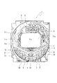
本実施例によるパチンコ機50には図10に記載するような演出ケース37が設けられている。なお、図10は演出ケース37の正面図である。この演出ケース37は図11の演出ケース37配置場所説明図に表すように遊技盤1の背面であり、演出図柄表示装置6の前面に配置される。なお、演出図柄表示装置6の前面に演出ケース37を配置する構成であるが、演出ケース37には図10に記載するように窓部42a(43a)が構成されており、該窓部42a(43a)に透明な透視部材(前透視部材42、後透視部材43)が設けられているので、演出図柄表示装置6に表示される内容が見えなくなることはない。
ただ、詳しくは後述するがこの演出ケース37内で浮遊物38を舞い上がらせる構成であり、この浮遊物38を舞い上がらせている間は、多少、演出図柄表示装置6に表示される表示内容が見難くなる。
The
However, as will be described in detail later, the structure is such that the floating
図12は演出ケース37の分解斜視図である。図12に記載するように演出ケース37は大きく分けると、演出ケース本体40、演出ケースカバー41、演出ケース本体40の前窓部42aに設けられた前透視部材42、演出ケースカバー41の後窓部43aに設けられた後透視部材43の部品から構成されている。
演出ケース本体40と演出ケースカバー41の間には浮遊物38(図12では省略)、浮遊物38を演出ケース37内で舞い上がらせるための吹上ファン39、演出ケース37内で発生した静電気を演出ケース37外に放出するための導電線90、浮遊物38が吹上ファン39の中に入り込むのを防ぐための浮遊物進入防止部材、浮遊物38を演出ケース37の中央下部から舞い上がらせるための吹上台48、浮遊物38に光をあてるためのLED基板に設けられた演出ケース発光LED91、後述する外ガイド部材45の一部をなす風抜き穴が施された振分部45aなどが設けられる。
なお、演出ケース本体40には、後述する内ガイド部材44、外ガイド部材45の一部が一体に形成されている。
FIG. 12 is an exploded perspective view of the
Between the
The production case
図13は吹上ファン39、浮遊物進入防止部材、LED基板、振分部45aを備えた状態の演出ケース本体40の裏面図である(なお、浮遊物38、導電線90は入っていない)。
図13に記載するように演出ケース本体40の前窓部42aのサイド及び上部の端に内ガイド部材44が設けられている。内ガイド部材44は前窓部42aの中央上部には設けられていないほか、前窓部42aの上部(端)に設けられた内ガイド部材42aは中央に近づくにつれ上側に上がるように傾斜が施されている。これは、詳しくは後述するが、浮遊物38が停留することを防止するためである。
内ガイド部材44の外側には外ガイド部材45が設けられている。この外ガイド部材45は、内ガイド部材44とは異なり前窓部42aの中央上部にも設けられている。ただ、前窓部42aの中央上部に設けられた外ガイド部材45は逆山状(中央に近づくにつれ下側に傾斜している)になっており、振分部45aを形成している。なお、この振分部45aには、吹上ファン39から排出された風が外ガイド部材45の外側に抜けるための風抜き穴が施されている。また、振分部45a以外にも外ガイド部材45の両上隅にも風抜き穴が施されている。
また、外ガイド部材45は、前窓部42aのサイドから前窓部42aの下部へR(状)を画いており、このR状の部分の下部(両側とも)に吹上ファン39を設置している。また、外ガイド部材45の端(下側)には浮遊物進入防止部材が設けられている。
なお、この内ガイド部材44と外ガイド部材45で浮遊物通路46を形成している。また、外ガイド部材45と演出ケース本体40の端に設けられた壁とで風通路47を形成している。なお、吹上ファン39は、この風通路47の一番下方に設置されている。
また、演出ケース本体40の両端(横側)には、演出ケース発光LED91が設けられたLED基板が設けられている。この演出ケース発光LED91にて舞い上がった浮遊物38を照らす構成になっている。なお、本実施例では、白い浮遊物38を使用して演出ケース発光LED91はフルカラーLEDを使用しているので浮遊物38を様々な色で照らすことが出来、遊技者を楽しませる。また、本実施例では、浮遊物38を照らす色によって大当りになる割合を変更している。例えば浮遊物38が青色で照らされると、その時の変動は20%の確率で大当りし、浮遊物38が赤色で照らされると、その時の変動は50%の確率で大当りするように設定するなどして、照らす色により期待感を変化させている。
前窓部42aの中央下部には、山状の吹上台48が設けられており、該吹上台48の傾斜部分が浮遊物38の貯留部49になっている。浮遊物38は吹上ファン39が作動していないときには、この貯留部49に留まっている。
なお、吹上台48の天辺部分(頂上部分)も前窓部42aよりも下方にあるので、遊技者からは吹上台48が見えないほか、貯留部49に溜まっている浮遊物38も見えない。
なお、図14は、図13を斜めから見た斜視図である。
FIG. 13 is a rear view of the production case
As shown in FIG. 13,
An
The
The floating
In addition, LED boards on which production case
A mountain-shaped blast stand 48 is provided at the center lower portion of the
In addition, since the top part (top part) of the blasting
FIG. 14 is a perspective view of FIG. 13 viewed from an oblique direction.
図15は風の動きと浮遊物38の動きを表した図である。図15のA(左側の図)が風の動きを表した図であり、図15のB(右側)が浮遊物38の動きを表した図である。
図15に記載するように吹上ファン39の吹出口39aは吹上台48の傾斜部分、つまり、貯留部49に向けられている。図15のAに記載しているように吹上ファン39が作動すると(風を出力すると)、風は吹上台48の傾斜面にぶつかり、演出ケース37の中央下部より上昇していく。演出ケース37の中央下部より上昇した風は、窓部(前窓部42a、後窓部43a)よりもさらに上昇し、外ガイド部材45の一部をなす振分部45aにぶつかる。振分部45aは上述したように風抜き穴が施されているので、その風抜き穴を抜けた風は左右の風通路47に分かれて流れていく。一方、風抜き穴から抜けなかった風は、左右の浮遊物通路46に分かれて流れていく。
風通路47に流れた風は、風通路47(サイドの部分)をどんどん下降していき吹上ファン39の吸込口39bに流れる。一方、浮遊物通路46に流れた風は、外ガイド部材45上部隅に設けられた風抜き穴にぶつかり、風抜き穴を抜けた風は風通路47に流れ、風抜き穴を抜けなかった風は、浮遊物通路46(サイドの部分)をどんどん下降していく。
一方、浮遊物38の動きは図15Bに記載するように風の動きと同様に演出ケース37の中央下部より上昇する。演出ケース37の中央下部より上昇した浮遊物38は、窓部(前窓部42a、後窓部43a)よりもさらに上昇するものもあるが、窓部(前窓部42a、後窓部43a)の途中で落下するものもある。途中で落下した浮遊物38は再び貯留部49に戻り、窓部(前窓部42a、後窓部43a)よりもさらに上昇した浮遊物38は、振分部45aにぶつかり左右の浮遊物通路46に振り分けられる。
なお、風抜き穴の一つの穴の大きさは浮遊物38の1個の大きさよりも小さく構成されているので、風抜き穴から浮遊物38が抜けることはない。
振り分けられた浮遊物38は浮遊物通路46を通って落下していく。なお、浮遊物38が内ガイド部材44に乗った場合でも上述したように前窓部42aの上部に設けられた内ガイド部材44は斜めに傾斜している(中央に近づくほど高くなっている)ので、浮遊物38はすべり落ちて窓部(前窓部42a、後窓部43a)の横に設けられて浮遊物通路46に流れる。サイドの浮遊物通路46を落下した浮遊物38は、外ガイド部材45のR部を通って貯留部49に戻る。
FIG. 15 is a diagram illustrating the movement of the wind and the movement of the floating
As shown in FIG. 15, the air outlet 39 a of the
The wind that has flown into the
On the other hand, as shown in FIG. 15B, the movement of the floating
In addition, since the size of one hole of the air vent hole is configured to be smaller than one size of the suspended
The distributed floating
図16は浮遊物38が貯留されている状態から、舞い上がり、落下していくまでの状態を表した図である。なお、図16のAは浮遊物38が貯留部49に留まっている状態を表した図(吹上ファン39が作動していない状態の図)であり、図16のBは浮遊物38が舞い上がっている状態を表した図であり、図16のCは、浮遊物38が落下していく状態を表した図である。
本実施例では、浮遊物38として、難燃性発泡ビーズ(直径約3mmの円状のもの)を使用している(なお、1個の風抜き穴の大きさ及び1個の浮遊物進入防止部材の穴の大きさは共に直径約1.5mmになっている。)。また、上述したように、演出ケース発光LED91による発光によって、浮遊物38が鮮やか、かつ、様々な色に見えるように浮遊物38の色は白になっている。
しかし、浮遊物38をこのように限定するわけではなく、材質などは紙やプラスチックなどが考えられるほか、形状も立体でなくてもよい。ようは、出力される風によって舞い上がるものならどのような物であってもよい。また、演出ケース内37に封入する浮遊物38の数も何個でもよいが、多くの浮遊物38を封入しておいたほうが、遊技者によりインパクトを与えることが出来る。
図16に記載するように左右にある貯留部49には、導電線90が入り込む構成になっている。この導電線90は導電部材で形成されており、演出ケース37(貯留部49)に溜まっている静電気を外に放出するために設けられている。なお、図は省略しているが、導電線90の演出ケース37より外に出ている部分は、パチンコ機50の外に静電気を放出するためのアース線と繋がっている。また、本実施例では、吹上台48の一部も導電部材で形成され、その導電部材で形成されている部分も上記したアース線に繋がっている。
本構成のように、細かいもの(浮遊物38)を多く舞い上がらせる構成だと浮遊物38同士が接触して多くの静電気が発生するが、このような静電気対策を施しているので静電気による不具合は発生しない。
FIG. 16 is a diagram showing a state from the state in which the suspended
In this embodiment, flame retardant foam beads (circular shape having a diameter of about 3 mm) are used as the suspended matter 38 (note that the size of one air vent hole and one suspended matter entry prevention). The size of the hole of each member is about 1.5 mm in diameter.) In addition, as described above, the color of the floating
However, the suspended
As shown in FIG. 16, the
As in this configuration, if a small object (floating matter 38) is made to fly a lot, floating
図16のAに記載しているように吹上ファン39が作動していないときには(吹上ファン39より風が出力されていないときには)、浮遊物38は、吹上台48の左右に設けられた貯留部49に貯留されている。なお、上述したように吹上ファン39の吹出口39aの前にも浮遊物38が貯留される構成になっているが浮遊物進入防止部材が設けられているので、浮遊物38が吹上ファン39の中に入ってしまう恐れはない。
図16のBに記載しているように吹上ファン39が作動すると吹上台48により、窓部(前窓部42a、後窓部43a)の中央下部より舞い上がる。窓部(前窓部42a、後窓部43a)よりも上に舞い上がった浮遊物38は振分部45aによって左右の浮遊物通路46に振り分けられる。
図16のCに記載しているように吹上ファン39の作動が停止すると浮遊物通路46に振り分けられた浮遊物38は窓部(前窓部42a、後窓部43a)の横の浮遊物通路46を落下し、R部を経て貯留部49に戻る。また、振分部45aまで届かなかった浮遊物38も窓部(前窓部42a、後窓部43a)を落下していき貯留部49に戻る。
なお、浮遊物38を舞い上がらせる構成だと、高く舞い上がった浮遊物38が落下するのに時間がかかってしまい、次の変動が開始されても遊技者にその浮遊物38が見えてしまう可能性が高いが、本構成にすることで高く舞い上がった浮遊物38は窓部(前窓部42a、後窓部43a)の外側に設けられた浮遊物通路46を通るので次の変動が始まった際には遊技者が浮遊物38を見る可能性を極端に低くすることが出来、遊技者に意図しない期待感を与えることはなくなる。
As shown in FIG. 16A, when the blowing
As shown in FIG. 16B, when the blow-up
As shown in FIG. 16C, when the operation of the blow-up
In addition, if it is configured to make the floating
図17は、主制御装置80及びサブ制御装置である音声・ランプ統合制御装置83が行なう処理を表す説明図である。
図17に記載するように主制御装置80は遊技球が第1始動口11あるいは第2始動口12に入球した際に抽出した乱数値によって大当り遊技(特別遊技)を行なうか否か決定するほか、大当り遊技を行うか否かを報知する特別図柄の変動時間を決定し、その特別遊技抽選の結果及び特別図柄の変動時間を含んだ表示制御コマンドをサブ制御装置である音声・ランプ統合制御装置83に送信する。
なお、図17に記載した変動時間は説明のために記載したものであり、本来はもっと沢山の変動時間が存在する。
音声・ランプ統合制御装置83は、送られてきた表示制御コマンド(特別遊技抽選の結果及び特別図柄の変動時間)により、演出図柄表示装置6にて表示する擬似図柄の表示内容の決定及び吹上ファン39を作動させる(吹上ファン39から風を出力し、浮遊物38を舞い上がらせる)か否かを図17に記載しているように決定する。
また、本実施例では図17の下方に記載しているように吹上ファン39による風の吹出し威力が3段階(最小、標準、最大)に変化可能な構成になっており、この風の吹出し威力もサブ制御装置である音声・ランプ統合制御装置83が決定する。また、本実施例では、演出ケース37の左右に設けられた吹上ファン39の各々を個別に制御可能になっている。つまり、演出ケース37の向かって右側に配置された吹上ファン39が作動していなく、演出ケース37の向かって左側に配置された吹上ファン39が最大の威力で風を吹き出しているときもある。これも音声・ランプ統合制御装置83が決定及び制御を行なう。
また、吹上ファン39の作動開始時期及び作動終了時期も吹上ファン39が決定する。
FIG. 17 is an explanatory diagram showing processing performed by the
As shown in FIG. 17, the
Note that the variation times shown in FIG. 17 are described for the sake of explanation, and there are many more variation times.
The voice / lamp integrated
Further, in this embodiment, as shown in the lower part of FIG. 17, the wind blowing power by the blow-up
The blow-up
図18は、吹上ファン39の作動状態の例を表したタイムチャートである。
図18の上側に記載されているタイムチャートは、変動時間が30秒の例であり、変動開始から所定時間経過後に演出ケース37の向かって右側の吹上ファン39(図18では右吹上ファンと記載、以後、右吹上ファンと記載)と演出ケース37の向かって左側の吹上ファン39(図18では左吹上ファンと記載、以後、左吹上ファンと記載)が同時に作動するが、右吹上ファン39は吹き出し威力は標準であり、左吹上ファン39は吹き出し威力は最大になっている。
吹上ファン39(右吹上ファン39、左吹上ファン39)が作動してから所定期間経過後、右吹上ファン39も左吹上ファンも同時に吹き出し威力が変化する。右吹上ファン39は吹き出し威力が標準から最大に変化し、左吹上ファン39は吹き出し威力が最大から標準に変化する。
吹上ファン39(右吹上ファン39、左吹上ファン39)の吹き出し威力が変化してから所定期間経過後に両吹上ファン39は作動を停止する。
図18の下側に記載されているタイムチャートは、変動時間が40秒の例であり、変動開始から所定時間経過後に右吹上ファン39と左吹上ファン39が同時に同じ吹き出し威力(最小)で作動する。
両吹上ファン39は作動してから所定時間経過後に作動を停止する。両吹上ファン39が作動を停止してから所定時間経過後に両吹上ファン39が同時で同じ吹き出し威力(最大)で作動する。
そして、両吹上ファン39は作動してから所定時間経過後に作動を停止する。
なお、これは変動時間が30秒(40秒)であったら常にこのように吹上ファン39が作動するというわけではなく、同じ変動時間であっても異なる作動態様の場合もある。
なお、図18の変動時間が30秒の例及び変動時間が40秒の例に記載しているように、変動時間が何秒であろうと、吹上ファン39の作動態様がどのような態様であろうと、主制御装置80によって決定された特別図柄の変動時間(図18でいう30秒又は40秒)の残り変動時間が、少なくとも決定された特別図柄の変動時間(図18でいう30秒又は40秒)の1/10の時間になる前に吹上ファン39を停止させる構成になっている。
具体的に記載すると、主制御装置80が決定した変動時間が30秒であった場合には、少なくとも残りの変動時間が、全変動時間(30秒)の1/10である3秒になる前には必ず吹上ファン39の作動を停止させる。また、主制御装置80が決定した変動時間が40秒であった場合には、少なくとも残りの変動時間が、全変動時間(40秒)の1/10である4秒になる前には必ず吹上ファン39の作動を停止させる。
このような構成にすることで、より確実に吹上ファン39を作動させた変動の次の変動中に浮遊物38が舞い上がっているという事態を防ぐことが出来る。
FIG. 18 is a time chart showing an example of the operating state of the blow-up
The time chart shown in the upper side of FIG. 18 is an example in which the fluctuation time is 30 seconds, and after a predetermined time has elapsed from the start of fluctuation, the blowing
After a lapse of a predetermined period after the blowing fan 39 (the
Both blowing
The time chart shown at the bottom of FIG. 18 is an example in which the variation time is 40 seconds, and the
Both blowing
Then, both the blow-up
Note that this does not always mean that the blow-up
Note that, as described in the example of the variation time of 30 seconds and the variation time of 40 seconds in FIG. 18, the operation mode of the blowing
More specifically, when the variation time determined by the
By adopting such a configuration, it is possible to prevent a situation in which the suspended
図19は演出ケース37内に吹上ファン39だけでなく、吹下ファン92も備えた構成を表した図である(別実施例である)。
なお、図19は図13と同様に吹上ファン39、浮遊物進入防止部材、LED基板、振分部45aを備えた状態(吹下ファン92も備えられている)の演出ケース本体40の裏面図である。また、図13と同様な部分は図13と同符号になっている。
図19に記載するように、振分部45aの上方である風通路47に吹下ファン92は備えられている。吹下ファン92の吹出口92aは振分部45aの裏側に向けられており、吹下ファン92から出力される風は、振分部45aの風抜き穴から下方に向けて出力される。
この吹下ファン92の作動(風の出力)は、吹上ファン39の作動(風の出力)が停止してから開始される構成になっている。
また、この吹下ファン92の作動は、特別図柄の変動が終了する前には停止される。
なお、図18に記載されている変動時間が40秒の例のように、吹上ファン39を1回の変動の中で複数回作動させる場合には、その変動の中で一番最後の吹上ファン39の作動が終了したときのみ吹下ファン92を作動させる構成でよい。
また、吹上ファン39が作動した変動に対して必ず吹下ファン92を作動させる必要はない。例えば、図18の変動時間が40秒の例で、2回吹上ファン39を作動させるのではなく初めに行なわれる吹上ファン39の作動のみ行なわれる場合など、吹上ファン39の作動終了後、残り変動時間が長い場合には吹下ファン92を作動させる必要はない。
また、吹上ファン39の作動が停止してから浮遊物38が未だに舞い上がっているか否かを検知する検知手段を設け、該検知手段によって浮遊物38が未だに浮遊していると判断した場合に吹下ファン92を作動させる構成にしてもよい。
このように、振分部45aの風抜き穴から風が下方に吹き出すように吹下ファン92を風通路47に配置し、吹上ファン39の作動が終了した後に吹下ファン92を作動させるようにして吹上ファン39が作動が終了してある程度時間が経過しているのにも係らず未だ浮遊している浮遊物38を吹下ファン92から出力される風によって強制的に窓部(前窓部42a、後窓部43a)よりも下方に落下させるので、さらに確実に吹上ファン39を作動させた変動の次の変動中に浮遊物38が舞い上がっているという事態を防ぐことが出来る。
FIG. 19 is a diagram showing a configuration in which not only the blow-up
19 is a rear view of the production case
As shown in FIG. 19, a blow-
The operation of the blowing fan 92 (wind output) is configured to start after the operation of the blowing fan 39 (wind output) is stopped.
Further, the operation of the blow-
In the case where the blowing
Further, it is not always necessary to operate the blow-
In addition, a detecting means for detecting whether or not the suspended
In this manner, the blow-
1・・・・遊技盤
3・・・・遊技領域
6・・・・演出図柄表示装置
7・・・・普通図柄表示装置
9・・・・特別図柄表示装置
11・・・第1始動口
12・・・第2始動口
14・・・大入賞口
37・・・演出ケース
38・・・浮遊物
39・・・吹上ファン
39a・・・吹出口
39b・・・吸込口
40・・・演出ケース本体
41・・・演出ケースカバー
42・・・前透視部材
42a・・・前窓部
43・・・後透視部材
43a・・・後窓部
44・・・内ガイド部材
45・・・外ガイド部材
45a・・・振分部
46・・・浮遊物通路
47・・・風通路
48・・・吹上台
49・・・貯留部
50・・・パチンコ機
51・・・外枠
52・・・前枠
53、54・・・ヒンジ
70・・・内枠
80・・・主制御装置
81・・・払出制御装置
82・・・演出図柄制御装置(サブ制御装置)
83・・・音声・ランプ統合制御装置(サブ制御装置)
85・・・電源基板
90・・・導電線
91・・・演出ケース発光LED
92・・・吹下ファン
92a・・・吹出口
DESCRIPTION OF
83 ... Voice / lamp integrated control device (sub-control device)
85 ...
92 ... blowdown fan 92a ... outlet
Claims (3)
前記表示装置の前面に、前記表示装置の表示領域が可視可能な窓部が形成され、該窓部の前面を浮遊可能な浮遊物が封入されているとともに前記浮遊物を舞い上がらせるための吹上ファンを備えた演出ケースを配置し、
該演出ケースは、
前記窓部の両サイド及び前記窓部の中央部を除く上側に配置された内ガイド部材と、該内ガイド部材の外側及び前記窓部の上側中央部に配置された外ガイド部材とにより前記窓部の外側に形成した、前記表示装置の前面に舞い上がった前記浮遊物が通る浮遊物通路と、
前記窓部の下側中央に山状に形成された吹上台と、
該吹上台の両傾斜面に前記浮遊物を溜めておく貯留部と、が設けられ、
前記窓部の上側中央部に配置された前記外ガイド部材は、風抜き穴が施された逆山状の振分部を備え、
前記浮遊物通路を通る前記浮遊物を遊技者から見えないようにするとともに前記浮遊物通路を通った前記浮遊物を、前記貯留部に流下させるようにし、
前記吹上ファンを、当該吹上ファンから出力される風が前記貯留部に当たるように配置したことを特徴とする弾球遊技機。 In a ball game machine equipped with a display device for displaying a change stop of a symbol indicating a lottery result to a player,
A window portion in which a display area of the display device can be seen is formed on the front surface of the display device, and a floating material capable of floating on the front surface of the window portion is enclosed, and a blowing fan for causing the floating material to rise Place a production case with
The production case is
The inner guide member disposed on the upper side excluding both sides of the window portion and the central portion of the window portion, and the outer guide member disposed on the outer side of the inner guide member and the upper central portion of the window portion. A floating passage formed on the outside of the section, through which the floating floating up to the front surface of the display device passes ,
A blast stand formed in a mountain shape in the lower center of the window,
A storage part for storing the suspended matter on both inclined surfaces of the blast stand, and
The outer guide member disposed in the upper center portion of the window portion includes an inverted mountain-shaped distribution portion provided with an air vent hole,
The floating matter passing through the floating passage is made invisible to a player and the floating matter passing through the floating passage is caused to flow down to the storage section.
A bullet ball game machine, wherein the blowing fan is arranged so that wind output from the blowing fan hits the storage section.
該主制御装置から送られるコマンドをもとに制御されるサブ制御装置と、を備え、
前記主制御装置は、遊技球が始動口に入球した際に抽出する乱数値によって、遊技者に有利な状態である特別遊技を行なうか否かの抽選(以下、「特別遊技抽選」という)及び該特別遊技抽選の結果を報知するまでの時間(以下、「変動時間」という)の決定を行い、該決定された変動時間に従って前記特別遊技抽選の結果を特別図柄の確定表示によって報知するほか、前記決定された変動時間及び前記特別遊技抽選の結果を含む表示制御コマンドを前記サブ制御装置に送信し、
前記サブ制御装置は、前記表示制御コマンドに応じて前記特別図柄の擬似演出を行なう擬似図柄を前記表示装置にて表示するための制御を行なうようにし、
さらに、前記サブ制御装置は、前記表示制御コマンドに応じて前記吹上ファンを作動させるか否か及び前記吹上ファンの作動態様を決定するとともに、前記吹上ファンの作動を制御するようにし、
決定された前記変動時間及び吹上ファンの作動態様が何れであっても決定された前記変動時間が終了する前に前記吹上ファンの作動を停止させるようにしたことを特徴とする請求項1記載の弾球遊技機。 A main controller that controls the entire gaming machine;
A sub-control device controlled based on a command sent from the main control device,
The main control device determines whether or not to perform a special game that is advantageous to the player based on a random number value extracted when the game ball enters the start opening (hereinafter referred to as “special game lottery”). And determining the time until the result of the special game lottery is notified (hereinafter referred to as “variable time”), and notifying the result of the special game lottery by a special symbol confirmation display according to the determined variable time. A display control command including the determined variation time and the result of the special game lottery is transmitted to the sub-control device;
The sub-control device performs control for displaying a pseudo symbol for performing a pseudo effect of the special symbol on the display device according to the display control command,
Further, the sub-control device determines whether or not to operate the blowing fan according to the display control command and the operating mode of the blowing fan, and controls the operation of the blowing fan,
2. The operation of the blow-up fan is stopped before the determined fluctuation time ends regardless of the determined variation time and the operation mode of the blow-up fan. A ball game machine.
前記吹上ファンの作動が終了したあとに前記吹下ファンを作動させるように設定したことを特徴とする請求項1乃至2に記載の弾球遊技機。 A blow-down fan controlled by the sub-control device installed so that the wind hits the air vent hole from the outside of the outer guide member;
3. The ball game machine according to claim 1, wherein the blow-down fan is set to operate after the operation of the blow-up fan is finished.
Priority Applications (1)
| Application Number | Priority Date | Filing Date | Title |
|---|---|---|---|
| JP2006305155A JP4923201B2 (en) | 2006-11-10 | 2006-11-10 | Bullet ball machine |
Applications Claiming Priority (1)
| Application Number | Priority Date | Filing Date | Title |
|---|---|---|---|
| JP2006305155A JP4923201B2 (en) | 2006-11-10 | 2006-11-10 | Bullet ball machine |
Publications (3)
| Publication Number | Publication Date |
|---|---|
| JP2008119183A JP2008119183A (en) | 2008-05-29 |
| JP2008119183A5 JP2008119183A5 (en) | 2011-10-20 |
| JP4923201B2 true JP4923201B2 (en) | 2012-04-25 |
Family
ID=39504592
Family Applications (1)
| Application Number | Title | Priority Date | Filing Date |
|---|---|---|---|
| JP2006305155A Expired - Fee Related JP4923201B2 (en) | 2006-11-10 | 2006-11-10 | Bullet ball machine |
Country Status (1)
| Country | Link |
|---|---|
| JP (1) | JP4923201B2 (en) |
Families Citing this family (4)
| Publication number | Priority date | Publication date | Assignee | Title |
|---|---|---|---|---|
| JP5299991B2 (en) * | 2008-03-31 | 2013-09-25 | 株式会社大一商会 | Game machine |
| JP2020000397A (en) * | 2018-06-27 | 2020-01-09 | 株式会社三洋物産 | Game machine |
| JP2020000398A (en) * | 2018-06-27 | 2020-01-09 | 株式会社三洋物産 | Game machine |
| JP2020000399A (en) * | 2018-06-27 | 2020-01-09 | 株式会社三洋物産 | Game machine |
Family Cites Families (7)
| Publication number | Priority date | Publication date | Assignee | Title |
|---|---|---|---|---|
| JP3558601B2 (en) * | 2001-03-12 | 2004-08-25 | 協和電子工業株式会社 | Slot machine |
| JP2003117085A (en) * | 2001-10-12 | 2003-04-22 | Heiwa Corp | Game machine and announcing method of game machine |
| JP3795426B2 (en) * | 2002-04-25 | 2006-07-12 | 株式会社内藤商会 | Pachinko machine |
| JP4044370B2 (en) * | 2002-05-28 | 2008-02-06 | 株式会社ソフィア | Pachinko machine |
| JP2004121551A (en) * | 2002-10-02 | 2004-04-22 | Takao:Kk | Pinball game machine |
| JP4000302B2 (en) * | 2003-02-14 | 2007-10-31 | 株式会社ソフィア | Game machine |
| JP2006296550A (en) * | 2005-04-18 | 2006-11-02 | Sanyo Product Co Ltd | Game machine |
-
2006
- 2006-11-10 JP JP2006305155A patent/JP4923201B2/en not_active Expired - Fee Related
Also Published As
| Publication number | Publication date |
|---|---|
| JP2008119183A (en) | 2008-05-29 |
Similar Documents
| Publication | Publication Date | Title |
|---|---|---|
| JP4188202B2 (en) | Game machine | |
| JP2004329226A (en) | Game machine | |
| JP5497406B2 (en) | Game machine | |
| JPH0956895A (en) | Pachinko machine | |
| JP2009078052A (en) | Game machine | |
| JP4674816B2 (en) | Bullet ball machine | |
| JP5124731B2 (en) | Bullet ball machine | |
| JP4265822B2 (en) | Bullet ball machine | |
| JP5467222B2 (en) | Game machine | |
| JP4923201B2 (en) | Bullet ball machine | |
| JP5001709B2 (en) | Game machine | |
| JP2010158397A (en) | Pinball game machine | |
| JPH09225099A (en) | Pinball game machine | |
| JP5094007B2 (en) | Game machine | |
| JP7261187B2 (en) | game machine | |
| JP7191876B2 (en) | game machine | |
| JP7261186B2 (en) | game machine | |
| JP7186190B2 (en) | game machine | |
| JP7186189B2 (en) | game machine | |
| JP2008017904A (en) | Pinball game machine | |
| JP2004000324A (en) | Pachinko game machine | |
| JP3808807B2 (en) | Game machine | |
| JP2005211120A (en) | Pinball machine | |
| JP5597801B2 (en) | Bullet ball machine | |
| JP6014453B2 (en) | Game machine |
Legal Events
| Date | Code | Title | Description |
|---|---|---|---|
| A621 | Written request for application examination |
Free format text: JAPANESE INTERMEDIATE CODE: A621 Effective date: 20091026 |
|
| A521 | Request for written amendment filed |
Free format text: JAPANESE INTERMEDIATE CODE: A523 Effective date: 20110906 |
|
| A131 | Notification of reasons for refusal |
Free format text: JAPANESE INTERMEDIATE CODE: A131 Effective date: 20111013 |
|
| A521 | Request for written amendment filed |
Free format text: JAPANESE INTERMEDIATE CODE: A523 Effective date: 20111130 |
|
| TRDD | Decision of grant or rejection written | ||
| A01 | Written decision to grant a patent or to grant a registration (utility model) |
Free format text: JAPANESE INTERMEDIATE CODE: A01 Effective date: 20111227 |
|
| A01 | Written decision to grant a patent or to grant a registration (utility model) |
Free format text: JAPANESE INTERMEDIATE CODE: A01 |
|
| A61 | First payment of annual fees (during grant procedure) |
Free format text: JAPANESE INTERMEDIATE CODE: A61 Effective date: 20111227 |
|
| FPAY | Renewal fee payment (event date is renewal date of database) |
Free format text: PAYMENT UNTIL: 20150217 Year of fee payment: 3 |
|
| R150 | Certificate of patent or registration of utility model |
Ref document number: 4923201 Country of ref document: JP Free format text: JAPANESE INTERMEDIATE CODE: R150 Free format text: JAPANESE INTERMEDIATE CODE: R150 |
|
| S531 | Written request for registration of change of domicile |
Free format text: JAPANESE INTERMEDIATE CODE: R313531 |
|
| FPAY | Renewal fee payment (event date is renewal date of database) |
Free format text: PAYMENT UNTIL: 20150217 Year of fee payment: 3 |
|
| R350 | Written notification of registration of transfer |
Free format text: JAPANESE INTERMEDIATE CODE: R350 |
|
| R250 | Receipt of annual fees |
Free format text: JAPANESE INTERMEDIATE CODE: R250 |
|
| R250 | Receipt of annual fees |
Free format text: JAPANESE INTERMEDIATE CODE: R250 |
|
| LAPS | Cancellation because of no payment of annual fees |