JP5299991B2 - Game machine - Google Patents
Game machine Download PDFInfo
- Publication number
- JP5299991B2 JP5299991B2 JP2008093921A JP2008093921A JP5299991B2 JP 5299991 B2 JP5299991 B2 JP 5299991B2 JP 2008093921 A JP2008093921 A JP 2008093921A JP 2008093921 A JP2008093921 A JP 2008093921A JP 5299991 B2 JP5299991 B2 JP 5299991B2
- Authority
- JP
- Japan
- Prior art keywords
- floating body
- floating
- game
- space
- production space
- Prior art date
- Legal status (The legal status is an assumption and is not a legal conclusion. Google has not performed a legal analysis and makes no representation as to the accuracy of the status listed.)
- Expired - Fee Related
Links
Images


Abstract
Description
本発明は、ぱちんこ遊技機(一般的に「パチンコ機」とも称する)や回胴式遊技機(一般的に「パチスロ機」とも称する)等の遊技機に関するものである。 The present invention relates to a gaming machine such as a pachinko gaming machine (generally also referred to as a “pachinko machine”) or a spinning-type gaming machine (generally also referred to as a “pachislot machine”).
従来より、パチンコ機等の遊技機において、遊技媒体として例えば遊技球が打ち込まれる遊技領域内には、多数の障害釘が所定のゲージ配列をなして備えられている他、遊技領域の適宜位置には、一般入賞口や、入球確率が変化するように左右に拡開する可動片(所謂チューリップ)を備えた可変入賞口や、可変入賞口の羽根を拡開させる始動口等が備えられており、これら一般入賞口、可変入賞口、及び始動口へ遊技媒体が入賞すると所定数の遊技媒体が払い出されるようになっている。また、遊技領域の略中央に所定の演出画像を表示可能な液晶表示装置等の演出表示手段を備えたものも知られている。 Conventionally, in gaming machines such as pachinko machines, a lot of obstacle nails are provided in a predetermined gauge arrangement in a gaming area where, for example, gaming balls are driven as gaming media, and at appropriate positions in the gaming area. Is equipped with a general winning opening, a variable winning opening with a movable piece (so-called tulip) that expands to the left and right so that the probability of entering the ball changes, a starting opening that opens the blades of the variable winning opening, etc. A predetermined number of game media are paid out when a game medium is awarded to the general winning opening, variable winning opening, and start opening. In addition, there is also known an effect display means such as a liquid crystal display device capable of displaying a predetermined effect image at substantially the center of the game area.
この種の遊技機として、演出表示手段の他に、遊技者側から内部を視認可能とされた演出空間を形成し、その演出空間内で下から上へ向かって吹き出す人工風によって演出物を遊動させて遊技状態に応じた演出を行うようにすることで、遊技者を楽しませて興趣を高められるようにしたものが提案されている(例えば、特許文献1,2)。 As this type of gaming machine, in addition to the effect display means, an effect space is formed in which the inside can be visually recognized from the player side, and the effect is moved by the artificial wind blown from the bottom upward in the effect space. Thus, it has been proposed that the player can be entertained and entertained by performing an effect according to the gaming state (for example, Patent Documents 1 and 2).
しかしながら、従来の遊技機では、人工風の作動によって最初に演出物が吹き上げられる時には、遊技者に対してある程度インパクトを与えることができるものの、その後は、人工風によって吹き上げられた演出物が、落下して再び人工風によって吹き上げられるようになっており、単に演出物が演出空間内を吹き上げられては落下するような循環動作を繰返すだけなので、単調な感じとなり遊技者によってはその演出に飽きてしまい、興趣を低下させてしまう恐れがある。 However, in the conventional gaming machine, when the production is blown up for the first time by the operation of the artificial wind, although it can give a certain impact to the player, after that, the production blown up by the artificial wind falls. Then, it is blown up again by artificial wind, and if the production is blown up in the production space, it simply repeats the circulating action of falling, so it feels monotonous and some players get tired of the production There is a risk that interest will be reduced.
また、従来の遊技機では、上述したように、演出物が吹き上げられては落下するような循環動作をするので、特許文献2のように、演出物として「花びら」や「雪の結晶」のような形状の演出物を用いた場合、一般的に花びらや雪の結晶は、上から下へ舞い降りるものであるのに対して、それら演出物を人工風によって下から上へ吹き上がる様も見えてしまうので、遊技者によっては、遊動する演出物に対して違和感を感じてしまい、遊技に対する興趣を低下させてしまう恐れがある。
In addition, in the conventional gaming machine, as described above, since the effect is circulated so that the effect is blown up and dropped, as in
そこで、本発明は上記の実情に鑑み、浮遊体による浮遊演出を飽き難くして遊技者の興趣が低下するのを抑制することが可能な遊技機の提供を課題とするものである。 In view of the above circumstances, an object of the present invention is to provide a gaming machine that makes it difficult to get tired of floating effects caused by a floating body and suppresses the interest of the player from decreasing.
手段1:遊技機において、
「遊技者の操作によって遊技媒体が打ち込まれる遊技領域と、
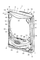
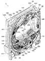
該遊技領域とは独立した所定広さの演出空間を形成する演出空間形成部材と、
該演出空間形成部材によって形成される前記演出空間内を浮遊可能とされた複数の浮遊体と、
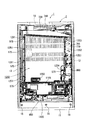
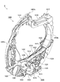
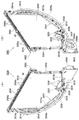
該浮遊体が通過可能とされ、前記演出空間内の下部と上部とを連絡する搬送路と、
該搬送路を通して前記演出空間の下部から上部へ前記浮遊体を搬送する搬送手段と、
該搬送手段によって前記浮遊体が搬送される前記搬送路を少なくとも遊技者側から視認不能とすると共に、前記演出空間の略中央を含む該演出空間の所定範囲内が遊技者側から視認可能となるように枠状に形成され、前記演出空間形成部材の前側に配置される前面遮蔽部材と
を具備する」ものであることを特徴とする。
Mean 1: In the gaming machine,
“A game area where game media is driven by the player's operation,
An effect space forming member that forms an effect space of a predetermined size independent of the game area;
A plurality of floating bodies capable of floating in the production space formed by the production space forming member;
The floating body is allowed to pass through, and a conveyance path that connects a lower part and an upper part in the production space;
Conveying means for conveying the floating body from the lower part to the upper part of the effect space through the conveying path;
The transport path through which the floating body is transported by the transport means is at least invisible from the player side, and the predetermined range of the effect space including the approximate center of the effect space is visible from the player side. And a front shielding member disposed in front of the effect space forming member ”.
ここで、「演出空間」としては、「上下左右方向に広がるような略板状の空間とされたもの」、「上下方向或いは左右方向へ延びる円筒形状の空間とされたもの」、「直方体形状の空間とされたもの」、「楕円球形状の空間とされたもの」、等が挙げられる。 Here, as the “production space”, “a substantially plate-like space spreading in the vertical and horizontal directions”, “a cylindrical space extending in the vertical or horizontal direction”, “a rectangular parallelepiped shape” And the like, and “the space made into an elliptical sphere”.
また、「浮遊体」としては、「板状の樹脂片からなるもの」、「板状の樹脂片を塑性変形させたもの」、「発泡樹脂からなるもの」、「ゴムからなるもの」、「紙からなるもの」、「金属からなるもの」、「(空気中で)浮力を有したもの」、「スパンコール」、等が挙げられる。また、「板状」、「中実」、「中空」、等の形態のものが挙げられる。なお、表面を多面形状としたり、表面に金属の蒸着層を備えるようにしたりしても良い。 In addition, the “floating body” includes “a plate-shaped resin piece”, “a plate-shaped resin piece plastically deformed”, “a foam resin”, “a rubber”, “ Examples include “made of paper”, “made of metal”, “having buoyancy (in the air)”, “sequin”, and the like. Moreover, the thing of forms, such as "plate shape", "solid", "hollow", is mentioned. The surface may be a polyhedral shape, or a metal vapor deposition layer may be provided on the surface.
また、「搬送路」としては、浮遊体が通過可能な大きさの流路であれば良く、「開口へ向かって円弧状に延びた形態のもの」、「開口へ向かって複数回折曲った形態のもの」、「開口へ向かって滑らかに曲線状に結ばれた形態のもの」、等が挙げられる。なお、搬送路を筒状としても良く、これにより、搬送中の浮遊体が搬送路から外れてしまうのを防止することができる。 In addition, the “conveyance path” may be a flow path having a size that allows the floating body to pass through, such as “a shape extending in an arc shape toward the opening”, “a shape that is bent a plurality of times toward the opening” And the like "," things that are smoothly curved toward the opening ", and the like. In addition, it is good also considering a conveyance path as a cylinder shape, and it can prevent that the floating body in conveyance remove | deviates from a conveyance path.
更に、「搬送手段」としては、「搬送路内に空気流(搬送流)を供給し、その空気流によって浮遊体を搬送するようにしたもの」、「浮遊体を収容可能な容器を有し、容器を移動させることで浮遊体を搬送するようにしたもの」、「浮遊体を載置可能な無端環状のベルトを有し、ベルトを駆動することで浮遊体を搬送するようにしたもの(ベルトコンベアを用いたもの)」、等が挙げられる。 Furthermore, as the “conveying means”, “an air flow (conveying flow) is supplied into the conveying path and the floating body is conveyed by the air flow”, “having a container that can accommodate the floating body. , One that transports the floating body by moving the container "," one that has an endless annular belt on which the floating body can be placed, and that transports the floating body by driving the belt ( And the like using a belt conveyor).
また、「前面遮蔽部材」としては、「遊技領域の後端を区画形成する(透明な)遊技パネルの前側に配置され、遊技領域内に打ち込まれた遊技媒体を転動させた後に遊技領域内へ還流可能とされたステージを有するセンター役物」、「遊技領域の後端を区画形成する透明な遊技パネルの後側で環状に配置され、少なくとも表面に所定の装飾が施された装飾体」、「遊技領域の後端を区画形成し、前後方向に貫通する開口部を有した不透明な遊技パネル」、「上述のセンター役物と装飾体とで構成されたもの」、「上述の装飾体と、装飾体を内部に支持する箱状の装飾体裏箱とでユニット化されたもの(例えば、前側裏ユニット)」、等が挙げられる。 In addition, the “front shielding member” is a “front-side shielding member” that is arranged in front of a (transparent) gaming panel that forms a rear end of the gaming area and rolls a gaming medium that has been driven into the gaming area. A center accessory having a stage that can be recirculated to the rear, "" decorative body that is annularly arranged behind the transparent gaming panel that defines the rear end of the gaming area, and at least a predetermined decoration is applied to the surface " , “Opaque game panel having an opening that defines the rear end of the game area and penetrates in the front-rear direction”, “Consists of the above-mentioned center object and decorative body”, “The above-mentioned decorative body And a box-like decorative body back box that supports the decorative body inside (for example, a front-side back unit) ”and the like.
ところで、従来の遊技機では、人工風によって演出物(浮遊体に相当)を演出空間内で下から上へ吹き上げるようにしており、例えば、人工風が強すぎると演出物が下へ落ち難くなり、また人工風が弱すぎると演出物が演出空間の上部まで吹き上がらずに演出物を充分に遊動させることができなくなるので、人工風の強さの範囲が比較的狭くなり人工風を発生させるファン(モータ)の回転制御を緻密に行う必要が発生しコストが増加する問題がある。 By the way, in the conventional gaming machine, the effect (equivalent to a floating body) is blown up from the bottom in the effect space by the artificial wind. For example, if the artificial wind is too strong, the effect is difficult to fall down. Also, if the artificial wind is too weak, the production will not blow up to the upper part of the production space, and the production will not be able to move sufficiently, so the range of strength of the artificial wind will be relatively narrow and generate artificial wind There is a problem that costs need to be increased because it is necessary to precisely control the rotation of the fan (motor).
また、演出空間における浮遊体を搬送する位置として、例えば、演出空間内の上部から下部へ浮遊体を搬送するようにした場合、浮遊体が下から上へ流れる必要があるので、浮遊体として浮力を有したものを用いるか、或いは、浮遊体の自重に抗して浮遊体が上昇するように演出空間内の空気(流体)を下から上へ移動するように流す必要があり、浮遊体が高価なものとなったり、演出空間内の流体を流動させる手段が別途必要となりその手段の存在によって相対的に演出空間が狭くなったりする恐れがある。 In addition, for example, when the floating body is transported from the upper part to the lower part in the production space as the position for transporting the floating body in the production space, the floating body needs to flow from the bottom to the top. It is necessary to flow the air (fluid) in the production space so that the floating body moves up from the bottom so that the floating body rises against the dead weight of the floating body. There is a risk that an expensive device or a means for causing the fluid in the production space to flow separately is required, and the production space is relatively narrowed due to the presence of the means.
また、演出空間内の一方の側部から他方の側部へ浮遊体を搬送するようにした場合、この場合もまた上述と同様に、演出空間内で他方の側部から一方の側部へ向かって積極的に流体(空気)を流さないと、浮遊体が搬送される一方の側部へ達するまでに、降下してしまったり上昇してしまったりして、浮遊体の動きを楽しませられなくなる恐れがあると共に、一方の側部で浮遊体を充分に収集して搬送することができなくなる恐れがある。 Also, when a floating body is transported from one side in the production space to the other side, in this case as well, the other side is directed from the other side to one side in the production space. If you do not actively flow fluid (air), the floating body will descend or rise before reaching the side where the floating body is transported, and you will not be able to enjoy the movement of the floating body. In addition, there is a risk that the floating body cannot be sufficiently collected and transported on one side.
手段1の構成によると、遊技機に、遊技者の操作によって遊技媒体が打ち込まれる遊技領域と、遊技領域とは独立した所定広さの演出空間を形成する演出空間形成部材と、演出空間内を浮遊可能とされた複数の浮遊体と、浮遊体が通過可能とされ演出空間内の下部と上部とを連絡する搬送路と、搬送路を通して演出空間の下部から上部へ浮遊体を搬送する搬送手段と、搬送路を少なくとも遊技者側から視認不能とすると共に、演出空間の略中央を含む演出空間の所定範囲内が遊技者側から視認可能となるように枠状に形成され、演出空間形成部材の前側に配置される前面遮蔽部材とを備えるようにしたものである。 According to the configuration of the means 1, a game area into which a game medium is driven by a player's operation in the gaming machine, an effect space forming member that forms an effect space having a predetermined width independent of the game area, and the effect space A plurality of floating bodies that are allowed to float, a conveyance path that allows the floating body to pass through and communicates with a lower part and an upper part in the production space, and a conveyance means that conveys the floating substance from the lower part to the upper part of the production space through the conveyance path And the conveyance path is formed in a frame shape so as to be invisible at least from the player side and to be visible from the player side within a predetermined range of the effect space including the approximate center of the effect space. And a front shielding member disposed on the front side.
これにより、遊技媒体が打ち込まれる遊技領域とは独立した演出空間内において、演出空間の下部から搬送手段により所定の搬送路を介して演出空間の上部へと搬送された浮遊体が、演出空間内の上部から下部へ向かって落下することとなり、演出空間内を浮遊落下する浮遊体の動きによって、これまでの遊技機には無い演出を遊技者に見せることができると共に、演出空間を形成する演出空間形成部材の前側に少なくとも搬送路を視認不能に遮蔽可能な枠状の前面遮蔽部材が配置されており、搬送路を介して搬送される浮遊体を遊技者から見えないようにすることができるので、遊技者に対して演出空間内へ浮遊体が限りなく次々に供給されるような装飾演出を見せることができ、「どうなっているのだろう?」などと思わせることが可能となり、浮遊体による浮遊演出を飽き難くして遊技に対する興趣が低下するのを抑制することができる。 As a result, in the production space independent of the game area into which the game medium is to be placed, the floating body conveyed from the lower part of the production space to the upper part of the production space via the predetermined conveyance path by the conveyance means It will fall from the upper part of the game to the lower part, and the movement of the floating body that floats and falls in the production space can show the player an effect that has not existed in conventional gaming machines, and also creates an effect space A frame-shaped front shielding member that can shield at least the conveyance path in an invisible manner is disposed on the front side of the space forming member, and the floating body conveyed through the conveyance path can be hidden from the player. Therefore, it is possible to show the player a decoration production in which floating bodies are supplied one after another infinitely in the production space, and it is possible to make the player think "What is going on?" Becomes, interest in the game and hardly tired stray effects by the floating body can be suppressed.
また、前面遮蔽部材によって演出空間の中央を含む所定範囲内のみが遊技者側から視認できるようにしている。つまり、前面遮蔽部材によって演出空間における視認可能範囲を区画するようにしているので、浮遊体を搬送手段により演出空間における上部の特定部位に搬送するようにした場合でも、演出空間内に搬送供給された浮遊体が、視認可能範囲内へ浮遊落下するまでの間に、演出空間内において前後左右方向へ拡散することが可能となり、演出空間における視認可能範囲内では広く拡散されて浮遊落下する浮遊体を遊技者に見せることができ、広い範囲で浮遊落下する浮遊体によってより遊技者の関心を強く引き付けられるものとすることができる。また、演出空間における視認可能範囲では浮遊体が広く拡散された状態で浮遊落下するので、浮遊体が演出空間内の偏った位置で浮遊することで浮遊体による装飾演出効果が低下してしまうのを防止することが可能となり、浮遊体の浮遊による装飾演出効果を高めることができ、多彩な演出により遊技者を楽しませて遊技に対する興趣が低下するのを抑制することができる。 In addition, only a predetermined range including the center of the effect space is visible from the player side by the front shielding member. In other words, since the visibility range in the effect space is defined by the front shielding member, even if the floating body is transported to the upper specific part in the effect space by the transport means, it is transported and supplied into the effect space. The floating body can diffuse in the front-rear and left-right directions in the production space before it floats and falls within the viewable range. Can be shown to the player, and the player's interest can be more strongly attracted by the floating body that floats and falls in a wide range. In addition, since the floating body floats and falls in a visually recognizable range in the production space, the floating body floats at a biased position in the production space, and the decoration production effect by the floating body is reduced. Can be prevented, and the effect of decoration effect due to the floating of the floating body can be enhanced, and it is possible to prevent the entertainment for the game from being reduced by making the player entertained by various effects.
更に、搬送手段により浮遊体を演出空間の下部から上部へ搬送するようにしている、つまり、演出空間内で浮遊体が上部から下部へ浮遊落下するようにしているので、浮遊体が自重によって落下することで自然に演出空間の下部へ到達することができ、浮遊体をその物性(例えば、形状、材質、重さ、等)に応じた違和感の無い自然な浮遊(落下浮遊)をさせることが可能となり、遊技者を楽しませて遊技に対する興趣が低下するのを抑制することができる。なお、例えば、浮遊体を「花びら」、「雪の結晶」、「紙吹雪」、「落ち葉」、等に見立てるようにした場合、上述したように、浮遊体が浮遊落下するので、遊技者に対して浮遊体の浮遊落下を違和感無く見せることができ、自然な感じで浮遊する浮遊体の動きを楽しませることができると共に、違和感により興趣が低下するのを抑制することができる。 Furthermore, the floating body is transported from the lower part to the upper part of the production space by the transport means, that is, the floating body is suspended and dropped from the upper part to the lower part in the production space. By doing so, it is possible to reach the lower part of the production space naturally, and to make the floating body naturally float (falling and floating) without a sense of incongruity according to its physical properties (for example, shape, material, weight, etc.) It becomes possible, and it can suppress that the interest to a game falls by entertaining a player. For example, if the floating body is regarded as “petals”, “snow crystals”, “confetti”, “fallen leaves”, etc., as described above, the floating body will float and fall. On the other hand, it is possible to show the floating fall of the floating body without a sense of incongruity, and it is possible to enjoy the movement of the floating body floating with a natural feeling, and it is possible to suppress the interest from being lowered due to the sense of incongruity.
また、上述したように、浮遊体を浮遊落下させるようにしているので、演出空間形成部材(演出空間)の下部で浮遊体を収集して搬送路へ受渡し易くすることができ、演出空間内で浮遊体を収集して受渡すための手段を別途備える必要が無く、その手段によって演出空間が狭められるのを防止することが可能となり、可及的に演出空間を広くすることができると同時に、相対的に演出空間における視認可能範囲を広くすることができ、広い範囲で浮遊する浮遊体を遊技者に見せて浮遊体による装飾演出効果をより高めることができると共に、遊技機に係るコストが増加するのを抑制することができる。 In addition, as described above, since the floating body is suspended and dropped, the floating body can be collected at the lower part of the production space forming member (production space) and easily delivered to the conveyance path. There is no need to separately provide a means for collecting and delivering floating bodies, and it is possible to prevent the production space from being narrowed by that means, and the production space can be made as wide as possible. The viewing range in the production space can be relatively widened, the floating body floating in a wide range can be shown to the player, and the decoration production effect by the floating body can be further enhanced, and the cost related to the gaming machine increases. Can be suppressed.
なお、前面遮蔽部材の遊技者から視認可能となる位置に所定の装飾が施された装飾体を備えるようにしても良く、これにより、その装飾体によって遊技機(遊技領域内)を装飾することができ、遊技機の見栄えを良くすることができると共に、装飾体の装飾効果によってより遊技者の関心を強く引き付けられる遊技機とすることができる。 In addition, you may make it provide the decoration body by which the predetermined | prescribed decoration was given to the position which becomes visible from the player of a front shielding member, and, thereby, decorates a game machine (in a game area) with the decoration body. Thus, the appearance of the gaming machine can be improved, and a gaming machine that can attract the player's attention more strongly by the decorative effect of the decorative body can be obtained.
また、前面遮蔽部材に、遊技領域内に打ち込まれた遊技媒体が転動可能なステージを有したセンター役物を備えるようにしても良く、これにより、ステージを備えた従来の遊技機と略同様の遊技が可能な遊技機とすることが可能となり、従来の遊技機に慣れた遊技者に違和感を与えてしまうのを抑制することができ、遊技する遊技機として本遊技機を選択し易くすることができる。 In addition, the front shielding member may be provided with a center accessory having a stage on which a game medium driven into the game area can roll, which is substantially the same as a conventional gaming machine equipped with a stage. It is possible to make a gaming machine capable of playing games, and it is possible to prevent a player who is used to conventional gaming machines from feeling uncomfortable, and to easily select this gaming machine as a gaming machine to play. be able to.
更に、浮遊体の表面を光の反射率が高いものとしても良く、これにより、演出空間内を浮遊する浮遊体の表面で、遊技機に備えられた発光手段や遊技機を設置する遊技ホール内の照明等からの光を遊技者側へ反射させることができると共に、その際に、浮遊体がユラユラと浮遊することで光の反射方向が変化し、浮遊体がキラキラ光っているように見せることが可能となり、浮遊体を綺麗に見せて浮遊体による演出効果をより高めることができる。 Furthermore, the surface of the floating body may have a high light reflectivity, so that the light emitting means provided in the gaming machine and the gaming machine are installed on the surface of the floating body floating in the production space. It is possible to reflect the light from the lighting etc. to the player side, and at that time, the floating body floats with the light, the reflection direction of the light changes, and the floating body appears to glitter It becomes possible, and the floating body can be shown beautifully, and the effect of the floating body can be further enhanced.
また、浮遊体の最大外形を、3mm〜8mmの範囲内とすることが望ましく、これにより、演出空間内で浮遊体を落下させた際に、浮遊体を確実にユラユラ・ヒラヒラと浮遊落下させることができ、遊技者に浮遊体の動きを楽しませて遊技に対する興趣が低下するのを抑制することができる。因みに、浮遊体の最大外形を3mm以上としたのは、これよりも浮遊体が小さくなると、演出空間を落下する浮遊体の形状を遊技者が認識し辛くなると共に、浮遊体の大きさ(重量)に対する空気抵抗や揚力が相対的に小さくなるので、浮遊体がヒラヒラと浮遊落下し辛くなり、浮遊体の動きを楽しませられなくなる恐れがあるからである。また、浮遊体の最大外形を8mm以下としたのは、これよりも浮遊体が大きくなると、浮遊体の大きさに対する空気抵抗や揚力の関係により演出空間内で浮遊体がヒラヒラする回数が少なくなり、浮遊体の動きを充分に楽しませられなくなる恐れがあると共に、浮遊体の重量が重くなるので空気流によって搬送するようにした場合、空気流を強くしなければならず空気流供給手段(搬送手段)が大型化する問題があるためであり、また、浮遊体に比例して演出空間も大きくしなければならず遊技機の前後方向の寸法が大きくなって既存の島設備に遊技機を設置することができなくなる恐れがあるためである。なお、浮遊体の最大外形としては、4mm〜6mmの範囲内とすることが更に望ましく、これにより、上述した作用効果を確実に奏することができる。 In addition, it is desirable that the maximum outer shape of the floating body is within a range of 3 mm to 8 mm, so that when the floating body is dropped in the production space, the floating body is surely floated and dropped with fluttering and fluttering. It is possible to make the player enjoy the movement of the floating body and to prevent the interest in the game from being lowered. Incidentally, the maximum outer shape of the floating body is set to 3 mm or more. If the floating body becomes smaller than this, it becomes difficult for the player to recognize the shape of the floating body falling in the production space and the size (weight) of the floating body. This is because the air resistance and the lift force to) are relatively small, and it is difficult for the floating body to float and fall, making it difficult to enjoy the movement of the floating body. In addition, the maximum outer shape of the floating body is set to 8 mm or less. If the floating body is larger than this, the number of times the floating body flutters in the production space is reduced due to the relationship between the air resistance and lift with respect to the size of the floating body. In addition, there is a risk that the movement of the floating body will not be fully enjoyed, and the weight of the floating body will increase, so if it is transported by air flow, the air flow must be strengthened and the air flow supply means (carrying This is because there is a problem that the size of the game machine is large, and the production space must be increased in proportion to the floating body, and the size of the game machine in the front-rear direction increases, and the game machine is installed on the existing island equipment. This is because there is a risk that it will not be possible. Note that the maximum outer shape of the floating body is more preferably in the range of 4 mm to 6 mm, so that the above-described operational effects can be reliably achieved.
更に、搬送手段として搬送路内に搬送流として空気等の流体を流すことで浮遊体を搬送させるようにしても良く、これにより、搬送手段として浮遊体を収容した容器を移動させるようにしたものやベルトコンベアを用いたものとした場合と比較して、搬送流を供給する手段(例えば、ファン)のみで浮遊体を搬送することができ、搬送手段に係る構成を簡略化して小型化することができると共に、搬送手段の小型化により演出空間(演出空間形成部材)を相対的に大きくすることが可能となり、より広い範囲で浮遊体を浮遊させて遊技者に与えるインパクトを高くすることができ、遊技に対する興趣が低下するのを抑制することができる。 Furthermore, the floating body may be transported by flowing a fluid such as air as a transport flow in the transport path as the transport means, and thereby the container containing the floating body is moved as the transport means. Compared to the case where a belt conveyor is used, the floating body can be transported only by means for supplying a transport flow (for example, a fan), and the configuration relating to the transport means can be simplified and miniaturized. It is possible to make the production space (production space forming member) relatively large by reducing the size of the transport means, and the impact on the player can be increased by floating the floating body in a wider range. , It is possible to suppress a decrease in interest in games.
また、演出空間内の上部に供給された浮遊体を、演出空間内で拡散させる拡散浮遊手段を更に備えるようにしても良く、これにより、演出空間内の略全体に浮遊体が拡散浮遊するので、演出空間における視認可能範囲では確実に浮遊体を全体的に拡散浮遊させることができ、浮遊体による演出効果をより高めることができると共に、遊技者を楽しませて興趣が低下するのを抑制することができる。 Moreover, you may make it further provide the spreading | diffusion floating means to which the floating body supplied to the upper part in production space diffuses in production space, and, thereby, a floating body diffuses and floats substantially in the whole production space. In addition, the floating body can be reliably diffused and suspended in the visible range in the production space, the production effect by the floating body can be further enhanced, and the entertainment can be prevented from being reduced by reducing the entertainment. be able to.
更に、演出空間形成部材を、前後方向よりも上下左右方向が大きく、前後方向の寸法が10mm〜50mmの範囲内となる演出空間を形成可能な大きさとしても良く、これにより、演出空間形成部材によって演出空間を上下左右方向が広い板状の空間とすることができ、正面視における遊技領域内での演出空間の占める割合を比較的多くすることが可能となり、演出空間を目立たせることができるので、その演出空間内を浮遊す浮遊体による演出も目立たせることができ、遊技者に対する訴求力の高い遊技機とすることができる。また、演出空間形成部材を前後方向が薄い箱状(板状)としているので、遊技機における前後方向の寸法が必要以上に大きくなるのを抑制することが可能となり、遊技ホールにおける遊技機を設置するための既存の島設備にも設置することができる。更に、演出空間形成部材によって演出空間の前後方向の寸法が10mm〜50mmの範囲内となるようにすることで、浮遊落下する浮遊体を演出空間内で前後方向の異なる位置に容易に位置させることが可能となり、浮遊体の浮遊落下による装飾演出や発光手段による発光装飾に対して奥行感をより高めることができる、より遊技者を楽しませて遊技に対する興趣が低下するのを抑制することができると共に、演出空間内を浮遊落下する浮遊体をより目立たせて遊技者に対する訴求力の高い遊技機とすることができる。因みに、演出空間における前後方向の寸法の下限を10mm以上としたのは、これよりも小さいと、浮遊体が演出空間内で自由に移動し難くなり浮遊体の動きを楽しませられなくなると共に、演出空間内で浮遊体が拡散し難くなるためである。また、演出空間における前後方向の寸法の上限を50mm以下としたのは、これよりも大きいと、遊技機全体の前後方向の寸法が大きくなりすぎて、遊技ホールにおける既存の島設備に本遊技機を設置することができなくなる恐れがあるためである。なお、演出空間における前後方向の寸法を、15mm〜30mmの範囲内とすることが望ましく、これにより、上述した作用効果を確実に奏することができる。 Further, the effect space forming member may be of a size capable of forming an effect space in which the vertical and horizontal directions are larger than the front and rear direction and the dimension in the front and rear direction is within the range of 10 mm to 50 mm. The production space can be made into a plate-like space with wide vertical and horizontal directions, and the proportion of the production space in the game area in the front view can be made relatively large, and the production space can be made conspicuous. Therefore, the effect by the floating body floating in the effect space can be made conspicuous, and a gaming machine with a high appeal to the player can be obtained. In addition, since the production space forming member is a box shape (plate shape) with a thin front and rear direction, it is possible to prevent the front and rear direction dimension of the gaming machine from becoming larger than necessary, and a gaming machine is installed in the gaming hall. It can also be installed in existing island facilities. Furthermore, by making the dimension of the production space in the front-rear direction within the range of 10 mm to 50 mm by the production space forming member, the floating body that floats and falls can be easily positioned at different positions in the front-rear direction in the production space. It is possible to enhance the feeling of depth with respect to the decoration effect due to the floating fall of the floating body and the light emission decoration by the light emitting means, and it is possible to further delight the player and reduce the interest in the game. At the same time, the floating body that floats and falls in the production space can be made more conspicuous, and a gaming machine with high appeal to the player can be obtained. By the way, the lower limit of the dimension in the front-rear direction in the production space is set to 10 mm or more. If it is smaller than this, the floating body will be difficult to move freely in the production space and the movement of the floating body will not be enjoyed. This is because floating bodies are difficult to diffuse in the space. In addition, the upper limit of the dimension in the front-rear direction in the production space is set to 50 mm or less. If it is larger than this, the dimension in the front-rear direction of the entire gaming machine becomes too large, and this gaming machine is added to the existing island equipment in the gaming hall. This is because there is a risk that it will not be possible to install. In addition, it is desirable for the dimension of the front-back direction in production space to be in the range of 15 mm-30 mm, and this can show | play the effect mentioned above reliably.
また、演出空間(演出空間形成部材)の後側に所定の演出画像を表示可能な演出表示手段を配置すると共に、演出空間を通して演出表示手段の演出画像を視認できるようにしても良く、これにより、演出表示手段に表示される演出画像の前側を浮遊体が浮遊することとなるので、浮遊体による演出をより多彩なものとすることができ、遊技機のインパクトを高めることができると共に、飽き難くして遊技に対する興趣が低下するのを抑制することができる。 Further, an effect display unit capable of displaying a predetermined effect image is arranged behind the effect space (effect space forming member), and the effect image of the effect display means may be visible through the effect space. Since the floating body floats on the front side of the effect image displayed on the effect display means, the effect by the floating body can be made more diverse, and the impact of the gaming machine can be increased and tired. It is possible to prevent the interest in games from being reduced.
手段2:手段1の構成において、
「前記前面遮蔽部材は、
少なくとも前記搬送路によって連絡される前記演出空間の下部と上部とが、遊技者側から視認不能となるように遮蔽する」ものであることを特徴とする。
Means 2: In the constitution of means 1,
"The front shielding member is
At least a lower part and an upper part of the effect space communicated by the transport path are shielded so as to be invisible from the player side.
ところで、搬送手段により搬送路を介して浮遊体を演出空間の下部から上部へ搬送するようにした場合、演出空間の下部で浮遊体を搬送路側へ受渡すところや、演出空間の上部で浮遊体を搬送路側から供給するところが遊技者側から見えてしまうと、浮遊体が循環する流れを認識することができ、遊技者によっては浮遊体が演出空間を浮遊落下する仕組みが判ることで、浮遊体による演出が楽しめなくなり興趣を低下させてしまう恐れがある。 By the way, when the floating body is transported from the lower part to the upper part of the production space by the conveyance means, the floating body is delivered to the conveyance path side in the lower part of the production space or in the upper part of the production space. Can be seen from the player side, the flow that the floating body circulates can be recognized, and depending on the player, it can be seen how the floating body floats and falls in the production space. There is a possibility that the production by can not be enjoyed and the interest is lowered.
手段2の構成によると、前面遮蔽部材によって、少なくとも搬送路により連絡される演出空間の下部と上部とを遊技者側から視認不能となるように遮蔽するようにしたものである。
According to the configuration of the
これにより、前面遮蔽部材により演出空間の下部と上部とを少なくとも遊技者側から遮蔽するようにしているので、演出空間の下部で浮遊体を搬送路側へ受渡すところや、演出空間の上部で浮遊体を搬送路側から供給するところ等を遊技者から見えなくすることが可能となり、演出空間における視認可能範囲を浮遊体が浮遊落下する仕組みを判り難くして遊技者を不思議がらせることができ、浮遊体等に対する関心を高めて遊技に対する興趣が低下するのを抑制することができる。 As a result, the lower part and the upper part of the production space are shielded at least from the player side by the front shielding member, so that the floating body is delivered to the conveyance path side at the lower part of the production space, and floats at the upper part of the production space. It is possible to hide the place where the body is supplied from the transport path side from the player, and it is difficult to understand the mechanism that the floating body floats and falls within the visible range in the production space, and the player can be wondered, It is possible to suppress the interest in the floating body and the like and to reduce the interest in the game.
また、前面遮蔽部材により演出空間の下部と上部とを遮蔽するようにしているので、遮蔽された演出空間の下部では搬送路側へ受渡すために広く浮遊落下してきた浮遊体を収集するスペースを確保することができると共に、遮蔽された演出空間の上部では搬送路側から供給された浮遊体を演出空間内で広く拡散させるためのスペースを確保することができ、而して、前面遮蔽部材により形成される演出空間の視認可能範囲では広く拡散された浮遊体のみを遊技者側に確実に見せることが可能となり、浮遊体が演出空間内の偏った位置で浮遊することで浮遊体による装飾演出効果が低下してしまうのを防止することができ、浮遊体の浮遊落下による装飾演出効果をより高めることがでる。 In addition, since the lower part and the upper part of the production space are shielded by the front shielding member, a space is collected in the lower part of the production space for collecting floating bodies that have fallen and fallen widely for delivery to the transport path side. It is possible to secure a space for widely diffusing the floating body supplied from the conveyance path side in the production space, and thus formed by the front shielding member. In the viewable range of the production space, it is possible to show only the widely diffused floating body to the player side, and the floating body floats at a biased position in the production space, so that the decorative production effect by the floating body is achieved. It can prevent that it falls, and can raise the decoration production effect by the floating fall of a floating body more.
手段3:手段1又は手段2の構成において、
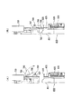
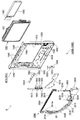
「前記遊技領域の外周を区画形成し、遊技媒体を案内可能な外レール及び内レールを有した枠状の前構成部材と、
該前構成部材の後側に配置され、前記遊技領域の後端を区画形成する透明板状の遊技パネルと、
該遊技パネルの外周を覆うように前側から該遊技パネルを着脱可能に保持すると共に、前記前構成部材を前側に支持可能とされ、前記遊技領域と略対応する大きさで前後方向に貫通する貫通口を有した枠状のパネルホルダと
を更に具備し、
該パネルホルダの後側に前記演出空間形成部材が配置されていると共に、前記遊技パネルの前側又は後側の少なくとも一方に前記前面遮蔽部材が配置されている」ものであることを特徴とする。
Means 3: In the constitution of means 1 or means 2,
“A frame-shaped front component member having an outer rail and an inner rail that can guide the game medium by partitioning the outer periphery of the game area;
A transparent plate-like game panel disposed on the rear side of the front component member and defining a rear end of the game area;
The game panel is detachably held from the front side so as to cover the outer periphery of the game panel, and the front component member can be supported on the front side, and penetrates in the front-rear direction in a size substantially corresponding to the game area. A frame-like panel holder having a mouth,
The effect space forming member is disposed on the rear side of the panel holder, and the front shielding member is disposed on at least one of the front side or the rear side of the game panel.
ここで、「遊技パネル」としては、透明板状であれば良く、その素材として、「アクリル樹脂」、「ポリカーボネイト樹脂」、「ABS樹脂」、「ポリプロピレン」、「ポリアリレート樹脂」、「メタクリル樹脂」、「ガラス」、等が挙げられる。なお、遊技パネルとしてアクリル樹脂を用いることが望ましく、このアクリル樹脂は、他の透明な部材と比較して、透明度が高く、遊技パネルの後側に配置される可動役物や演出表示手段等をより見易くすることができる。 Here, the “game panel” may be a transparent plate, and the materials thereof are “acrylic resin”, “polycarbonate resin”, “ABS resin”, “polypropylene”, “polyarylate resin”, “methacrylic resin”. ”,“ Glass ”, and the like. In addition, it is desirable to use acrylic resin as the game panel, and this acrylic resin has high transparency compared to other transparent members, and it is possible to use a movable accessory or effect display means arranged on the rear side of the game panel. It can be made easier to see.
また、「遊技パネルを着脱可能に保持する」ものとしては、「遊技パネルの少なくとも略対向する二辺に係合部を備えると共に、パネルホルダに遊技パネルの係合部と係合する被係合部を備え、係合部と被係合部とを係合させることで着脱可能に保持するもの」、「遊技パネルの適宜箇所に挿通孔を穿設し、その挿通孔を介してビス等をパネルホルダにねじ込むことで着脱可能に保持するもの」、等が挙げられる。更に、「保持段部」の深さとしては、「遊技パネルの前面と、パネルホルダの前面とが略同一面となる深さの段部」、「遊技パネルの前面がパネルホルダの前面よりも奥まった位置となる深さの段部」、等が挙げられる。 Further, “to hold the gaming panel so as to be detachable” includes “to be engaged with at least two substantially opposite sides of the gaming panel and engaging with the engaging portion of the gaming panel on the panel holder. ”And“ removably holding by engaging the engaging portion and the engaged portion ”,“ perforating an insertion hole at an appropriate position of the game panel, and inserting a screw or the like through the insertion hole What is detachably held by being screwed into the panel holder ". Furthermore, the depth of the “holding step portion” is “the step portion whose depth is such that the front surface of the game panel and the front surface of the panel holder are substantially flush with each other”, and “the front surface of the game panel is more than the front surface of the panel holder. A stepped portion having a depth that is a deep position ”.
手段3の構成によると、遊技機に、遊技領域の外周を区画形成し遊技媒体を案内可能な外レール及び内レールを有した枠状の前構成部材と、前構成部材の後側に配置され遊技領域の後端を区画形成する透明板状の遊技パネルと、遊技パネルの外周を覆うように前側から遊技パネルを着脱可能に保持すると共に、前構成部材を前側に支持可能とされ、遊技領域と略対応する大きさで前後方向に貫通する貫通口を有した枠状のパネルホルダとを更に備えた上で、パネルホルダの後側に演出空間形成部材を配置すると共に、遊技パネルの前側又は後側の少なくとも一方に前面遮蔽部材を配置したものである。
According to the configuration of the
これにより、演出空間形成部材をパネルホルダの後側、つまり、遊技領域を区画形成する遊技パネルの後側に配置しているので、浮遊体が浮遊落下する演出空間と、遊技媒体が打ち込まれる遊技領域とを容易に分離させることができ、浮遊体と遊技媒体とが互いに干渉するのを防止して、浮遊体による装飾演出と遊技媒体による遊技とを確実に楽しませられる遊技機とすることができる。 As a result, the effect space forming member is arranged on the rear side of the panel holder, that is, on the rear side of the game panel that defines the game area, so that the effect space in which the floating body floats and the game medium is driven It is possible to easily separate the area, prevent the floating body and the game medium from interfering with each other, and make a game machine that can surely enjoy the decoration effect by the floating body and the game by the game medium. it can.
また、演出空間形成部材の前側に配置される遊技パネルを透明板状としているので、遊技パネルを通して演出空間形成部材によって形成される演出空間(演出空間における視認可能範囲)を遊技者側から確実に視認させることが可能となり、演出空間内を浮遊落下する浮遊体の動きを楽しませることができ、上述と同様の作用効果を奏する遊技機とすることができる。なお、遊技パネルの所定形状の開口部を形成し、その開口部を通して演出空間を視認できるようにしても良い。 In addition, since the game panel arranged on the front side of the production space forming member is formed in a transparent plate shape, the production space (viewable range in the production space) formed by the production space forming member through the game panel is surely viewed from the player side. It can be visually recognized, and the movement of the floating body that floats and falls in the production space can be enjoyed, and a gaming machine having the same effects as described above can be obtained. Note that an opening of a predetermined shape of the game panel may be formed so that the effect space can be visually recognized through the opening.
更に、前面遮蔽部材を遊技パネルの前側又は後側の少なくとも一方に配置するようにしており、例えば、遊技パネルの後側に前面遮蔽部材を配置するようにした場合、前面遮蔽部材が遊技領域と干渉するのを防止することができるので、遊技領域が狭くなるのを可及的に抑制することが可能となり、遊技領域内で遊技媒体を確実に流通させて遊技媒体の動きを楽しませることができ、遊技媒体の動きによる遊技機本来の娯楽性を維持させて遊技に対する興趣が低下するのを抑制することができる。なお、前面遮蔽部材を遊技パネルの後側に配置するようにした場合、前面遮蔽部材に装飾体を備えるようにしても良く、これにより、透明な遊技パネルを通して前面遮蔽部材の装飾体を遊技者に視認させることができ、遊技領域(遊技機の遊技盤)をより目立たせて遊技者に対する訴求力の高い遊技機とすることができる。 Furthermore, the front shielding member is arranged on at least one of the front side or the rear side of the gaming panel. For example, when the front shielding member is arranged on the rear side of the gaming panel, the front shielding member is a gaming area. Since interference can be prevented, it becomes possible to suppress the narrowing of the game area as much as possible, and the game medium can be reliably distributed in the game area to enjoy the movement of the game medium. In addition, it is possible to maintain the original amusement of the gaming machine due to the movement of the game medium and to prevent the interest in the game from decreasing. When the front shielding member is arranged on the rear side of the game panel, the front shielding member may be provided with a decorative body, whereby the decorative body of the front shielding member is passed through the transparent gaming panel. The gaming area (game board of the gaming machine) can be made more conspicuous, and a gaming machine with high appeal to the player can be obtained.
また、前面遮蔽部材を遊技パネルの前側に配置するようにしても良く、これにより、遊技パネルの後側の空間をより広く取ることが可能となるので、演出空間形成部材(演出空間)における前後方向の寸法をより大きくすることが可能となり、浮遊体による浮遊落下演出の奥行感を高めてより目立つ遊技機とすることができると共に、奥行が増すことで浮遊落下する浮遊体の動きをより複雑な動きとすることができ、浮遊体の動きを楽しませて遊技に対する興趣が低下するのを抑制することができる。なお、前面遮蔽部材を、ステージを有したセンター役物としても良く、これにより、ステージを備えた従来の遊技機と略同様の遊技が可能な遊技機とすることが可能となり、従来の遊技機に慣れた遊技者に違和感を与えてしまうのを抑制することができ、遊技する遊技機として本遊技機を選択し易くすることができる。 In addition, the front shielding member may be arranged on the front side of the game panel, which allows a wider space on the rear side of the game panel, so that the front and rear in the production space forming member (production space) The size of the direction can be made larger, and the depth of the floating fall effect by the floating body can be enhanced to make it a more prominent gaming machine, and the movement of the floating body falling and falling becomes more complicated as the depth increases. The movement of the floating body can be enjoyed and the interest in the game can be prevented from decreasing. Note that the front shielding member may be a center accessory having a stage, which makes it possible to make a gaming machine capable of playing games similar to a conventional gaming machine equipped with a stage. It is possible to prevent the player who has become accustomed to feeling uncomfortable and to easily select this gaming machine as a gaming machine to play.
また、遊技パネルをパネルホルダに対して着脱可能に保持させるようにしており、接着固定していないので、遊技パネルとパネルホルダとを組立てるための組立工数が増加するのを抑制することができると共に、遊技パネルとパネルホルダとを容易に着脱することができるので、組立や、廃棄処分時等の分解に係る手間を簡略化することができる。 In addition, since the gaming panel is detachably held with respect to the panel holder and is not bonded and fixed, an increase in the number of assembly steps for assembling the gaming panel and the panel holder can be suppressed. Since the game panel and the panel holder can be easily attached and detached, it is possible to simplify the labor involved in disassembly during assembly and disposal.
なお、パネルホルダに前側から後方へ向かって窪んだ保持段部を形成し、その保持段部に遊技パネルを保持させるようにしても良く、これにより、パネルホルダの厚み内に遊技パネルを収めることが可能となり、遊技パネル、パネルホルダや、前構成部材等によって遊技盤を構成しても、その厚さが増加するのを抑制することができる。従って、遊技盤を既存のものと略同等の大きさのものとすることができるので、遊技機における遊技盤以外の部分を既存のものと共通化することができると共に、既存の製造ラインに載せることができ、製造に係るコストが増加するのを抑制することができる。 In addition, a holding step portion that is recessed from the front side to the rear side may be formed in the panel holder, and the gaming panel may be held in the holding step portion, and thereby the gaming panel is accommodated within the thickness of the panel holder. Even if the game board is constituted by a game panel, a panel holder, a front constituent member, or the like, it is possible to suppress an increase in thickness. Therefore, since the game board can be made to be approximately the same size as the existing one, the parts other than the game board in the gaming machine can be made common with the existing one and placed on the existing production line. It is possible to suppress an increase in manufacturing costs.
また、パネルホルダの厚さを、従来の遊技盤における木製合板の部分の厚さと対応した厚さ(18〜21mm、望ましくは、約19mm)とすると共に、遊技パネルの厚さをパネルホルダにおける厚さの約半分の厚さである8〜10mmの厚さとすることが望ましい。詳述すると、遊技パネルには多数の障害釘を植設する関係上、その厚さが8mmよりも薄いと障害釘を良好に保持することができなく恐れがあり、また、厚さが10mmよりも厚くても障害釘の保持が向上しないと共に遊技パネルの重量が必要以上に重くなる問題があるからである。これにより、(樹脂等の)透明板からなるパネルホルダや遊技パネルの厚さを最適なものとすることができる。 In addition, the thickness of the panel holder is set to a thickness (18 to 21 mm, preferably about 19 mm) corresponding to the thickness of the wooden plywood part in the conventional game board, and the thickness of the game panel is set to the thickness of the panel holder. It is desirable that the thickness is about 8 to 10 mm, which is about half the thickness. In detail, there are fears that the obstacle nail cannot be satisfactorily held when the thickness is less than 8 mm due to the planting of many obstacle nails in the game panel, and the thickness is more than 10 mm. This is because even if it is thick, the holding of the obstacle nail is not improved, and the weight of the game panel is increased more than necessary. Thereby, the thickness of the panel holder and game panel which consist of transparent plates (resin etc.) can be optimized.
手段4:手段1から手段3までの何れか一つの構成において、
「前記前面遮蔽部材は、
前記遊技領域内へ打ち込まれた遊技媒体を所定方向へ転動可能な転動面を備えている」ものであることを特徴とする。
Means 4: In any one configuration from means 1 to
"The front shielding member is
It has a rolling surface capable of rolling a game medium driven into the game area in a predetermined direction.
ここで、「転動面」としては、「遊技媒体を所定方向へ誘導させる棚状のもの(例えば、誘導棚)」、「遊技領域内を流下する遊技媒体が供給され、供給された遊技媒体を左右方向や前後方向へ転動させた後に、再び遊技領域内へ還流させるようにしたもの(例えば、ステージ)」、「遊技領域内の所定位置同士を連通するように形成された流路状のもの(例えば、ワープ通路、ゲート通路、等)」、等が挙げられる。 Here, as the “rolling surface”, a “shelf-shaped one that guides the game media in a predetermined direction (for example, a guide shelf)” or “game media flowing down in the game area is supplied, and the supplied game media "Rolling back and forth in the left-right direction and back-and-forth direction and then recirculating back into the game area (for example, stage)", "Flow path shape formed so as to communicate with predetermined positions in the game area (For example, warp passages, gate passages, etc.) "and the like.
手段4の構成によると、前面遮蔽部材に、遊技領域内へ打ち込まれた遊技媒体を所定方向へ転動可能な転動面を備えるようにしたものである。
According to the configuration of the
これにより、前面遮蔽部材に遊技媒体が転動可能な転動面を備えるようにしているので、転動面を転動する遊技媒体の動きによって遊技者を楽しませることができ、興趣が低下するのを抑制することができる。また、転動面によって枠状に形成された前面遮蔽部材の枠内(正面視で枠内と対応する位置)を遊技媒体が流下しないように誘導することができるので、演出空間における視認可能範囲の前側を遊技媒体が流通するのを回避させることが可能となり、遊技媒体と浮遊体とが重なって見えることで遊技媒体や浮遊体が見辛くなるのを防止することができ、遊技媒体や浮遊体を確実に視認させてそれらの動きを楽しませることができる。 Thereby, since the front shielding member is provided with a rolling surface on which the game medium can roll, the player can be entertained by the movement of the game medium rolling on the rolling surface, and the interest is reduced. Can be suppressed. In addition, since the game medium can be guided so as not to flow down in the frame of the front shielding member formed in a frame shape by the rolling surface (position corresponding to the frame in front view), the visible range in the production space It is possible to avoid the distribution of game media in front of the game media, and it is possible to prevent the game media and floating bodies from being difficult to see due to the appearance of the game media and floating bodies overlapping. It is possible to entertain those movements by making the body visible.
また、前面遮蔽部材における転動面を、遊技領域内に打ち込まれた遊技媒体が転動可能なステージとしても良く、これにより、ステージを備えた従来の遊技機と略同様の遊技が可能な遊技機とすることが可能となり、従来の遊技機に慣れた遊技者に違和感を与えてしまうのを抑制することができ、遊技する遊技機として本遊技機を選択し易くすることができる。また、転動面をステージとした場合、ステージの後側の空間に演出空間が配置されることとなるので、遊技者側からステージを見た場合、あたかもステージ上に浮遊体が浮遊落下しているように錯覚させることが可能となり、これまでの遊技機では見たこともない演出を遊技者に見せることができ、インパクトの高い演出によって遊技者を楽しませることができると共に、訴求力の高い遊技機とすることができる。 In addition, the rolling surface of the front shielding member may be a stage on which a game medium driven into the game area can roll, and thereby a game capable of playing a game similar to a conventional gaming machine having a stage. This makes it possible to prevent the player who is used to the conventional gaming machine from feeling uncomfortable and to easily select the gaming machine as a gaming machine to play. In addition, if the rolling surface is a stage, a production space will be placed in the space behind the stage, so if you look at the stage from the player's side, floating bodies will fall and fall on the stage. It is possible to make an illusion as if it were present, and it is possible to show the player an effect that has never been seen with a conventional gaming machine. It can be a gaming machine.
手段5:手段4の構成において、
「前記前面遮蔽部材は、
前記遊技パネルの前面に前側から支持され、転動する遊技媒体を前記遊技領域内へ還流可能とされた前記転動面としてのステージを有したセンター役物を備えている」ものであることを特徴とする。
Means 5: In the constitution of
"The front shielding member is
It is provided with a center accessory having a stage as the rolling surface that is supported from the front side on the front side of the gaming panel and is capable of returning the rolling gaming media to the gaming area. Features.
ここで、「ステージ」としては、「左右方向の略中央が最も低くなった湾曲状の転動面を有したもの」、「左右方向の両端が最も高くなると共に、左右方向の複数箇所が最も低くなるように波状に湾曲した転動面を有したもの」、「所定幅で左右方向に延びる転動面が後側から前側へ向かうにしたがって順次低くなるように階段状に複数配置されたもの」、「転動面の所定位置に遊技媒体が進入すると遊技領域内の所定位置から放出されるような進入口を有したもの」、「転動面の所定位置に遊技媒体が受入れられると所定数の遊技媒体が払出される入賞口を有したもの」、等が挙げられる。 Here, as the “stage”, “the one having a curved rolling surface whose lowest center in the left-right direction is the lowest”, “the both ends in the left-right direction are the highest, and a plurality of places in the left-right direction are the most `` With rolling surfaces curved in a wave shape so as to be lower '', `` Rolling surfaces extending in the left-right direction with a predetermined width are arranged in a plurality of steps so as to gradually decrease from the rear side toward the front side ”,“ Having an entrance that allows a game medium to be released from a predetermined position in the game area when the game medium enters a predetermined position on the rolling surface ”,“ predetermined when the game medium is received at a predetermined position on the rolling surface ” And the like having a winning opening through which a number of game media are paid out.
手段5の構成によると、前面遮蔽部材に、遊技パネルの前面に前側から支持され、転動する遊技媒体を遊技領域内へ還流可能とされた転動面としてのステージを有するセンター役物を備えるようにしたものである。
According to the configuration of the
これにより、前面遮蔽部材に、転動面としてのステージを有したセンター役物を備えるようにしているので、ステージを備えた従来の遊技機と略同様の遊技が可能な遊技機とすることが可能となり、従来の遊技機に慣れた遊技者に違和感を与えてしまうのを抑制することができ、遊技する遊技機として本遊技機を選択し易くすることができる。 As a result, since the front shielding member is provided with a center accessory having a stage as a rolling surface, it is possible to provide a gaming machine capable of playing substantially the same game as a conventional gaming machine equipped with a stage. Therefore, it is possible to prevent the player who is used to the conventional gaming machine from feeling uncomfortable, and it is possible to easily select the gaming machine as a gaming machine to play.
また、前面遮蔽部材に、転動面としてのステージを有したセンター役物を備えるようにしており、センター役物の枠内を通して後側に配置された演出空間を視認することができるので、蓋然的に、ステージの後側に演出空間が配置されることとなり、遊技者側からステージを見た場合、あたかもステージ上に浮遊体が浮遊落下しているように錯覚させることが可能となり、これまでの遊技機では見たこともない演出を遊技者に見せることができ、インパクトの高い演出によって遊技者を楽しませることができると共に、訴求力の高い遊技機とすることができる。 In addition, the front shielding member is provided with a center accessory having a stage as a rolling surface, and the production space arranged on the rear side through the frame of the center accessory can be visually recognized. The stage space will be placed behind the stage, and when viewing the stage from the player side, it will be possible to make the illusion that a floating body is floating on the stage. It is possible to show the player an effect that has never been seen with this game machine, entertain the player with a high impact effect, and make the game machine highly appealing.
手段6:手段1から手段5までの何れか一つの構成において、
「前記前面遮蔽部材は、
遊技者側から視認可能とされると共に環状に配置され、少なくとも表面に所定の装飾が施された装飾体を備えている」ものであることを特徴とする。
Means 6: In any one configuration from means 1 to
"The front shielding member is
It is characterized in that it is provided with a decorative body that is visible from the player side and is annularly arranged, and at least a predetermined decoration is applied to the surface.
ここで、所定の装飾が施された「装飾体」としては、「板状の部材の表面に印刷やシール等により図柄や模様等が施されたもの」、「植物や動物、建物、風景、自然物、幾何学模様等のレリーフが施されたもの」、「植物や動物、建物、風景、自然物、幾何学模様等が立体的に造形されたもの」、等が挙げられる。また、装飾体として、透光性部材や、不透光性部材等を用いても良いし、表面にメッキ層等を施しても良い。 Here, as the “decorative body” to which a predetermined decoration is applied, “the surface of the plate-like member is provided with a pattern or pattern by printing or sticking”, “plants and animals, buildings, landscapes, Natural objects, geometric patterns and other reliefs ”,“ plants, animals, buildings, landscapes, natural objects, geometric patterns, etc. three-dimensionally shaped ”and the like. Moreover, a translucent member, a non-translucent member, etc. may be used as a decoration body, and a plating layer etc. may be given to the surface.
手段6の構成によると、前面遮蔽部材に、遊技者側から視認可能とされると共に環状に配置され少なくとも表面に所定の装飾が施された装飾体を備えるようにしたものである。 According to the configuration of the means 6, the front shielding member is provided with a decorative body that is visible from the player side and is annularly arranged and at least a predetermined decoration is applied to the surface.
これにより、前面遮蔽部材に環状の装飾体が備えられているので、その装飾体によって演出空間における視認可能範囲の外周を装飾することが可能となり、演出空間を引き立てて演出空間内での演出に対する期待感を高めることができ、遊技者の興趣が低下するのを抑制することができると共に、演出空間周りの見栄えを良くして遊技者の関心を強く引き付けられる遊技機とすることができる。 Thereby, since the front decorative member is provided with an annular decorative body, it is possible to decorate the outer periphery of the visible range in the production space by the decoration body, and for the production in the production space by enhancing the production space. It is possible to increase the sense of expectation, to suppress the player's interests from being lowered, and to improve the appearance around the production space, thereby making it possible to make the gaming machine strongly attracting the player's interest.
また、前面遮蔽部材における装飾体を透明な遊技パネルの後側に配置するようにしても良く、これにより、遊技領域を形成する透明な遊技パネルの後側に、遊技機の機種を特徴付けるような装飾が施された装飾体が配置されているので、従来の遊技機のように遊技パネルの表面に施された平面的な絵や装飾物とは全くことなる印象を一見して遊技者に与えることが可能となり、遊技者の関心を強く引き付けて、本遊技機に対する期待感を高めて興趣が低下するのを抑制することができると共に、遊技者に対する訴求力が高くなり他の遊技機に対して本遊技機を大きく差別化することができ、遊技する遊技機として本遊技機を選択する可能性を高くすることができる。 In addition, the decorative body in the front shielding member may be arranged on the rear side of the transparent game panel, thereby characterizing the model of the gaming machine on the rear side of the transparent game panel forming the game area. Since the decoration body with decoration is arranged, it gives the player at a glance the impression that is completely different from the flat picture and decorations applied on the surface of the game panel like a conventional game machine It is possible to attract the player's interest and raise the expectation of this gaming machine and suppress the interest, and the appealing power to the player becomes higher. Thus, this gaming machine can be greatly differentiated, and the possibility of selecting this gaming machine as a gaming machine to be played can be increased.
なお、装飾体の後側にLED等の発光体を有した発光装飾手段を備えるようにしても良く、これにより、装飾体を発光装飾させることができるので、更に、遊技者を強く引き付けることが可能となり、本遊技機に対する期待感を高めることができると共に、他の遊技機よりも訴求力を高めることができ、遊技する遊技機として本遊技機を選択させ易くすることができる。 In addition, you may make it provide the light emission decoration means which has light-emitting bodies, such as LED, on the back side of a decoration body, and since a decoration body can be light-decorated by this, it can attract a player strongly further. This makes it possible to increase the sense of expectation of the gaming machine, to increase the appealing power compared to other gaming machines, and to facilitate the selection of the gaming machine as a gaming machine to play.
手段7:手段6の構成において、
「前記前面遮蔽部材は、
前記装飾体を後側から発光装飾させる発光装飾手段を更に備えている」ものであることを特徴とする。
Means 7: In the configuration of means 6,
"The front shielding member is
It further includes a light emitting decoration means for decorating the decorative body from the rear side ”.
ここで、「発光装飾手段」としては、「複数の発光体(例えば、LED)を備えたもの」、「複数色の光を発光可能とされた発光体を複数備えたもの」、「複数の発光体と、発光体の前面に配置される透明で所定色のレンズ部材とを備えたもの」、等が挙げられる。 Here, as “light emitting decoration means”, “one provided with a plurality of light emitters (for example, LEDs)”, “one provided with a plurality of light emitters capable of emitting light of a plurality of colors”, “a plurality of light emitters” And the like including a light-emitting body and a transparent and predetermined-colored lens member disposed on the front surface of the light-emitting body.
手段7の構成によると、前面遮蔽部材に、装飾体を後側から発光装飾させる発光装飾手段を更に備えるようにしたものである。 According to the structure of the means 7, the front shielding member is further provided with a light emitting decoration means for decorating the decorative body from the rear side.
これにより、発光装飾手段によって装飾体を発光装飾させることができるので、装飾体をより綺麗に見せるて遊技者を強く引き付けることができ、本遊技機に対する期待感を高めることができると共に、他の遊技機よりも訴求力を高めることができ、遊技する遊技機として本遊技機を選択させ易くすることができる。 As a result, the decorative body can be illuminated and decorated by the light emitting decoration means, so that the player can be strongly attracted by showing the decorative body more beautifully, and the expectation for the game machine can be enhanced. The appealing power can be increased as compared with the gaming machine, and this gaming machine can be easily selected as a gaming machine to play.
また、装飾体の後側に発光装飾手段を備えており、装飾体を透明や半透明等の透光性を有した部材により構成しても、発光装飾させることで装飾体の後側に配置される演出空間形成部材を見辛くして遮蔽部材としての機能を果たすことができるので、透光性を有した部材で装飾体を構成することで、前面遮蔽部材としての機能を低下させることなく、装飾体の意匠性を高めることが可能となり、より遊技者の関心を強く引き付けられるインパクトの高い装飾体とすることができる。 In addition, a light emitting decoration means is provided on the rear side of the decorative body, and even if the decorative body is made of a translucent member such as a transparent or translucent member, it is arranged on the rear side of the decorative body by emitting light. It is possible to fulfill the function as a shielding member by making it difficult to look at the production space forming member, so that the decorative body is composed of a translucent member without reducing the function as the front shielding member Therefore, it is possible to improve the design of the decorative body, and it is possible to provide a decorative body with high impact that can attract the player's interest more strongly.
手段8:手段6又は手段7の構成において、
「前記前面遮蔽部材は、
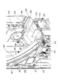
前側が開放された箱状で後壁の略中央に前記演出空間形成部材における前記演出空間の一部が遊技者側から視認可能となるような前後方向へ貫通する所定形状の開口部を備え、該開口部の外周で透明な前記遊技パネルを通して遊技者側から視認可能となるように前記装飾体を内部に支持すると共に後側に前記演出空間形成部材を支持可能とされ、前記パネルホルダの後側に取付けられる装飾体裏箱を有している」ものであることを特徴とする。
Means 8: In the constitution of means 6 or means 7,
"The front shielding member is
It has a box shape with a front side opened, and has an opening of a predetermined shape penetrating in the front-rear direction so that a part of the effect space in the effect space forming member can be visually recognized from the player side at the approximate center of the rear wall, The decorative body is supported inside so as to be visible from the player side through the game panel transparent on the outer periphery of the opening, and the effect space forming member can be supported on the rear side. It has a decorative box attached to the side ".
手段8の構成によると、前面遮蔽部材に、前側が開放された箱状で後壁の略中央に演出空間形成部材における演出空間の一部が遊技者側から視認可能となるような前後方向へ貫通する所定形状の開口部を有し、開口部の外周で透明な遊技パネルを通して遊技者側から視認可能となるように装飾体を内部に支持すると共に後側に演出空間形成部材を支持可能とされ、パネルホルダの後側に取付けられる装飾体裏箱を備えるようにしたものである。 According to the configuration of the means 8, the front shielding member is formed in a box shape with the front side opened in the front-rear direction so that a part of the effect space in the effect space forming member can be visually recognized from the player side at the approximate center of the rear wall. It has an opening of a predetermined shape that penetrates, and it can support the decoration body inside so that it can be seen from the player side through a transparent game panel on the outer periphery of the opening and can support the effect space forming member on the rear side And a decorative case back box attached to the rear side of the panel holder.
これにより、装飾体裏箱によって前面遮蔽部材の装飾体や演出空間形成部材を支持するようにしているので、装飾体裏箱を挟んで、演出空間形成部材と装飾体とが決められた位置に確実に支持されることとなり、装飾体により演出空間形成部材における演出空間の所望の位置を正確に遮蔽することができ、演出空間における視認可能範囲を確実に意図した範囲内として上述した作用効果を確実に奏する遊技機とすることができる。 Thereby, since the decorative body and the production space forming member of the front shielding member are supported by the decorative body back box, the production space forming member and the decorative body are located at a predetermined position across the decorative body back box. The desired position of the effect space in the effect space forming member can be accurately shielded by the decorative body, and the above-described effects are ensured that the visible range in the effect space is surely within the intended range. The gaming machine can be surely played.
また、装飾体裏箱の内部に装飾体を支持させるようにしているので、装飾体裏箱により前面遮蔽部材をユニット化することができ、装飾体裏箱をパネルホルダの後側に取付けるだけで前面遮蔽部材を取付けることができ、遊技機の組立てに係る手間を簡略化することができると共に、前面遮蔽部材に不具合が発生した場合、前面遮蔽部材を簡単に取外すことができ、メンテナンス性を向上させることができる。なお、装飾体裏箱内に装飾体を発光装飾させる発光装飾手段を支持させるようにしても良く、これにより、上述と同様の作用効果を奏することができる。 Moreover, since the decorative body is supported inside the decorative body back box, the front shielding member can be unitized by the decorative body back box, and only by attaching the decorative body back box to the rear side of the panel holder. Front shield member can be attached, simplifying the labor involved in assembling the gaming machine, and if the front shield member fails, the front shield member can be easily removed, improving maintainability Can be made. In addition, you may make it support the light emission decoration means to light-decorate a decoration body in a decoration body back box, and there exists an effect similar to the above by this.
更に、演出空間形成部材を装飾体裏箱の後側で支持するようにしているので、装飾体裏箱の後側に演出空間形成部材を支持させた状態で、装飾体裏箱をパネルホルダの後側に取付けると、前面遮蔽部材の装飾体と共に演出空間形成部材を同時に取付ける事ができ、遊技機の組立てに係る手間を簡略化して、遊技機に係るコストが増加するのを抑制することができる。 Furthermore, since the production space forming member is supported on the rear side of the decorative body back box, the decorative body back box is attached to the panel holder with the production space forming member supported on the rear side of the decorative body back box. When attached to the rear side, the production space forming member can be attached at the same time as the decorative body of the front shielding member, simplifying the labor involved in assembling the gaming machine, and suppressing the cost associated with the gaming machine from increasing. it can.
また、パネルホルダの後側に取付けられる装飾体裏箱内に装飾体を支持するようにしているので、蓋然的に、装飾体が透明な遊技パネルの後側に配置されることとなり、透明な遊技パネルの後側に配置された装飾体によって、従来の遊技機のように遊技パネルの表面に施された平面的な絵や装飾物とは全くことなる印象を一見して遊技者に与えることが可能となり、遊技者の関心を強く引き付けて、本遊技機に対する期待感を高めて興趣が低下するのを抑制することができると共に、遊技者に対する訴求力が高くなり他の遊技機に対して本遊技機を大きく差別化することができ、遊技する遊技機として本遊技機を選択する可能性を高くすることができる。 In addition, since the decorative body is supported in the decorative body back box attached to the rear side of the panel holder, the decorative body is placed on the rear side of the transparent gaming panel. To give the player a glance at the glance with a decoration placed on the back side of the gaming panel, which is completely different from the two-dimensional pictures and decorations on the surface of the gaming panel as in conventional gaming machines. It is possible to attract the player's interest, and to increase the sense of expectation for this gaming machine and to suppress the interest, and to increase the appeal to the player and to other gaming machines This gaming machine can be greatly differentiated, and the possibility of selecting this gaming machine as a gaming machine to be played can be increased.
手段9:手段3から手段8までの何れか一つの構成において、
「前記パネルホルダの後側に取付けられ、前側が開放された箱状で内部の略中央に前記演出空間形成部材を支持する浮遊体裏箱を更に具備する」ものであることを特徴とする。
Means 9: In any one configuration from
“It is a box-like shape that is attached to the rear side of the panel holder and is open on the front side, and further includes a floating body back box that supports the effect space forming member substantially in the center of the inside”.
手段9の構成によると、遊技機に、パネルホルダの後側に取付けられ、前側が開放された箱状で内部の略中央に演出空間形成部材を支持する浮遊体裏箱を更に備えるようにしたものである。 According to the configuration of the means 9, the gaming machine is further provided with a floating body back box that is attached to the rear side of the panel holder and supports the effect space forming member at a substantially central portion inside the box with the front side opened. Is.
これにより、箱状の浮遊体裏箱内に演出空間形成部材を支持させるようにしているので、演出空間形成部材の外形形状が矩形状以外の形状であっても、浮遊体裏箱によって全体の外形を整えることが可能となり、パネルホルダの後側に取付けた時に、演出空間形成部材に係る不要な出っ張りを無くしてスッキリさせることができ、遊技機を組立てる際や、遊技機を遊技ホールの島設備に設置する際等で、邪魔になったり他の部材と当接したりするのを防止することができ、作業性を向上させることができると共に、当接して破損するのを防止することができる。 Thereby, since the production space forming member is supported in the box-shaped floating body back box, even if the external shape of the production space forming member is a shape other than the rectangular shape, the whole body is formed by the floating body back box. It is possible to adjust the outer shape, and when attached to the rear side of the panel holder, it is possible to eliminate unnecessary protrusions related to the production space forming member, and it is possible to refresh the game machine when assembling the gaming machine or the island of the gaming hall When installed in equipment, it can be prevented from getting in the way or coming into contact with other members, improving workability and preventing from being damaged due to contact. .
なお、浮遊体裏箱を、パネルホルダの後側に前面遮蔽部材における装飾体裏箱を介して取付けるようにしても良く、これによっても、上述と略同様の作用効果を奏することができる。また、浮遊体裏箱の後側に演出表示手段を支持させるようにしても良い。 Note that the floating body back box may be attached to the rear side of the panel holder via the decorative body back box in the front shielding member, and this can also provide substantially the same operational effects as described above. Further, the effect display means may be supported on the rear side of the floating body back box.
手段10:手段9の構成において、
「前記浮遊体裏箱は、
前記前面遮蔽部材における前記装飾体裏箱を介して前記パネルホルダの後側に取付けられている」ものであることを特徴とする。
Means 10: In the constitution of means 9,
“The floating box is
It is attached to the rear side of the panel holder through the decorative body back box of the front shielding member ”.
ところで、パネルホルダの後側に前面遮蔽部材における装飾体裏箱が取付けられた状態で、浮遊体裏箱をパネルホルダの後側に直接取付けるようにした場合、浮遊体裏箱の取付部分を、後側から装飾体裏箱を越えて装飾体裏箱の前側へ延びださせる必要がある。つまり、浮遊体裏箱が後側から装飾体裏箱に対して覆い被さるような形となるので、蓋然的に、装飾体裏箱が浮遊体裏箱よりも小さいものとなってしまうと共に、パネルホルダの後側において装飾体裏箱と浮遊体裏箱とを直接取付けるためのスペースが必要となるので、これによっても、浮遊体裏箱よりも装飾体裏箱が小さいものとなり、装飾体裏箱が小さくなることで相対的に装飾体も小さくなってしまい、而して、装飾体による演出空間における視認可能範囲も小さくなるので、演出空間内を浮遊する浮遊体が見辛くなる恐れがある。 By the way, when the floating body back box is directly attached to the rear side of the panel holder in the state where the decorative body back box in the front shielding member is attached to the rear side of the panel holder, the mounting part of the floating body back box is It is necessary to extend from the rear side to the front side of the decorative body back box over the decorative body back box. In other words, since the floating body back box covers the decorative body back box from the rear side, the decorative body back box is likely to be smaller than the floating body back box. Since a space for directly mounting the decorative body back box and the floating body back box is required on the rear side of the holder, this also makes the decorative body back box smaller than the floating body back box. Since the decorative body becomes relatively small as a result of the decrease, the visible range in the rendering space by the decorative body is also small, and there is a risk that the floating body floating in the rendering space will be difficult to see.
手段10の構成によると、浮遊体裏箱を、前面遮蔽部材における装飾体裏箱を介してパネルホルダの後側に取付けるようにしたものである。
According to the structure of the
これにより、装飾体裏箱の後側に浮遊体裏箱を支持させることでパネルホルダの後側に浮遊体裏箱を取付けるようにしているので、パネルホルダの後側における裏箱の取付スペースを、装飾体裏箱を取付けるためのスペースだけで済み、装飾体裏箱が小さくなるのを抑制することが可能となり、而して、相対的に演出空間における視認可能範囲が小さくなるのを抑制することができ、演出空間内を浮遊落下する浮遊体が見辛くなるのを防止することができると共に、浮遊体を見易くすることができ、浮遊体による装飾演出を楽しませて遊技に対する興趣が低下するのを抑制することができる。 As a result, the floating body back box is attached to the rear side of the panel holder by supporting the floating body back box on the rear side of the decorative body back box. Only a space for mounting the decorative body back box is required, and it is possible to prevent the decorative body back box from becoming smaller, and thus relatively less visible range in the effect space is reduced. It is possible to prevent the floating body floating and falling in the production space from being hard to see, to make the floating body easy to see, and to enjoy the decoration production by the floating body and to reduce the interest in the game. Can be suppressed.
また、装飾体裏箱の後側に演出空間形成部材を内部に支持した浮遊体裏箱を取付けるようにしているので、装飾体裏箱の後側に浮遊体裏箱を取付けた状態で、装飾体裏箱をパネルホルダの後側に取付けると、前面遮蔽部材の装飾体と共に浮遊体裏箱、つまり、演出空間形成部材を同時に取付ける事ができ、遊技機の組立てに係る手間を簡略化して、遊技機に係るコストが増加するのを抑制することができる。 In addition, since the floating body back box that supports the production space forming member is attached to the rear side of the decorative body back box, the decoration is performed with the floating body back box attached to the rear side of the decorative body back box. When the body back box is attached to the rear side of the panel holder, the floating body back box, that is, the production space forming member can be attached at the same time with the decorative body of the front shielding member, simplifying the labor involved in assembling the gaming machine, An increase in the cost associated with the gaming machine can be suppressed.
手段11:手段1から手段10までの何れか一つの構成において、
「前記搬送手段によって搬送されることで前記浮遊体が浮遊する前記演出空間へ向けて複数色の光を照射可能な発光手段を更に具備する」ものであることを特徴とする。
Means 11: In any one configuration from means 1 to means 10,
“It further comprises light emitting means capable of emitting a plurality of colors of light toward the effect space where the floating body is floated by being conveyed by the conveying means”.
ここで、「発光手段」としては、「単一色光のみを発光可能とされた複数の発光体を有すると共に、単一色光として複数の異なる色を備えたもの」、「単一光源から複数色の光を発光可能な発光体を複数備えたもの」、「赤色光、緑色光、青色光、及び白色光を夫々独立して発光する四つの発光体を一つの発光体ユニットとし、その発光体ユニットを複数備えたもの」、等が挙げられる。また、「発光体」としては、「LED」、「白熱灯」、「蛍光灯」、「ネオン灯」、等が挙げられる。 Here, as the “light emitting means”, “a plurality of light emitters capable of emitting only a single color light and having a plurality of different colors as a single color light”, “a plurality of colors from a single light source” A plurality of light emitters capable of emitting the same light ”,“ four light emitters that independently emit red light, green light, blue light, and white light, respectively, as one light emitter unit, and the light emitters “A plurality of units”. Examples of the “light emitter” include “LED”, “incandescent lamp”, “fluorescent lamp”, “neon lamp”, and the like.
ところで、従来よりこの種の遊技機には、表面が所定形状に造形されると共に透光性を有した装飾部材と、装飾体の後側に配置され前方(遊技者側)へ向かって発光可能なLEDを有した発光基板とを備えた装飾体が遊技領域内の適宜位置に配置されており、遊技状態等に応じて発光基板のLEDを発光させることで装飾体を発光装飾させて、その発光演出により遊技者を楽しませられるようにしている。また、この装飾体を可動させるようにすることで、更に遊技者を楽しませられるようにしたものも提案されている(例えば、特開2007−202622号公報)。しかしながら、このような従来の遊技機では、装飾体における発光基板に実装されたLEDの発光色や点灯位置等を変化させることで装飾部材を様々な態様で発光装飾(発光演出)させることができ、遊技者を楽しませることができるものの、装飾体において装飾部材と発光基板との位置関係が常に略一定とされているので、基本的には同じ発光演出の繰返しとなり、遊技者によっては見慣れることで装飾体の発光演出によるインパクトが薄れて飽き易くなってしまい、遊技に対する興趣を低下させてしまう恐れがある。 By the way, in this type of gaming machine, the surface is shaped into a predetermined shape and the decorative member having translucency and the rear side of the decorative body are arranged to emit light toward the front (player side). A decorative body including a light emitting board having a suitable LED is arranged at an appropriate position in the game area, and the decorative body is illuminated and decorated by causing the LED of the light emitting board to emit light according to the gaming state, etc. The player is made entertained by the lighting effect. There has also been proposed a device that can make the player more entertaining by moving the decorative body (for example, Japanese Patent Application Laid-Open No. 2007-202622). However, in such a conventional gaming machine, the decoration member can be decorated in various ways (light emission effects) by changing the light emission color, lighting position, etc. of the LED mounted on the light emitting board in the decorative body. Although the player can be entertained, the positional relationship between the decorative member and the light-emitting board is always substantially constant in the decorative body, so basically the same light-emitting effect is repeated, and some players are familiar with it. Therefore, the impact due to the light emission effect of the decorative body may be diminished, and it may be easy to get tired, which may reduce the interest in the game.
手段11の構成によると、遊技機に、搬送手段によって搬送されることで浮遊体が浮遊する演出空間へ向けて複数色の光を照射可能な発光手段を更に備えるようにしたものである。
According to the configuration of the
これにより、浮遊体が浮遊落下する演出空間へ向けて発光手段から光を照射することができるので、その光により浮遊体を発光装飾させることができると共に、浮遊体が演出空間内で自由に浮遊落下することで発光手段における光源(発光体)と各浮遊体との位置関係が刻々と変化し、浮遊体に対する光の当り具合が常に変化することとなり、浮遊体の発光装飾を多彩なものとすることができ、より多彩な演出を遊技者に見せることで遊技に対する興趣が低下するのを抑制することができる。 As a result, light can be emitted from the light emitting means toward the production space where the floating body floats and falls, so that the floating body can be illuminated and decorated, and the floating body can float freely in the production space. When falling, the positional relationship between the light source (light emitting body) and each floating body in the light emitting means changes every moment, and the degree of light hitting the floating body always changes. It is possible to suppress the interest of the game from deteriorating by showing the player more various effects.
また、発光手段から複数色の光が演出空間内へ照射されており、浮遊体の浮遊位置や、浮遊体の向き等に応じて、浮遊体に照射される光の色や、浮遊体によって遊技者側へ反射する光の色が、変化することとなるので、一つの浮遊体が様々な色に発光装飾されると共に浮遊落下に伴って刻々と発光装飾態様が変化し、従来の装飾体では成し得なかったような複雑に変化する発光装飾(発光演出)を具現化することができ、遊技者に対するインパクトを高めて遊技に対する興趣が低下するのを抑制することができる。 Also, multiple colors of light are emitted from the light emitting means into the production space, and depending on the floating position of the floating body, the orientation of the floating body, etc., the color of the light irradiated to the floating body and the game depending on the floating body Since the color of the light reflected to the person side will change, one floating body will be decorated with various colors, and the luminous decoration will change every moment with the floating fall. It is possible to embody light emitting decorations (light emitting effects) that change in a complicated manner that could not be achieved, and it is possible to increase the impact on the player and suppress the interest in the game from being reduced.
更に、発光手段から複数色の光が演出空間内へ照射されているので、一つの浮遊体に対して複数色の光が当ることとなり、各色の当り具合(各色光の重なり具合、例えば、赤色光と白色光が重なった部分がピンク色となったり、赤色光と緑色光が重なったところが黄色となったりする)によって、一つの浮遊体においてその表面を複数の色に発光演出(発光装飾)することができると共に、演出空間内では複数の浮遊体が浮遊しており、各浮遊体同士の位置関係によっては発光手段からの光による浮遊体の影が他の浮遊体に投影されることとなるので、浮遊体に影が投影されることで、発光装飾を更に複雑で多彩なものとすることが可能となり、遊技者の関心を強く引き付けられる装飾とすることができ、遊技者を楽しませて興趣が低下するのを抑制することができる。 Furthermore, since multiple colors of light are radiated from the light emitting means into the effect space, multiple colors of light strike one floating body, and each color hit condition (overlapping condition of each color light, for example, red The surface where light and white light overlap becomes pink, or the portion where red light and green light overlap becomes yellow.) In addition, a plurality of floating bodies are floating in the production space, and depending on the positional relationship between each floating body, the shadow of the floating body due to the light from the light emitting means may be projected onto other floating bodies. Therefore, the shadows are projected onto the floating body, making it possible to make the light-emitting decoration more complex and versatile, making it a decoration that attracts the player's attention and amuses the player. Less interesting It is possible to suppress.
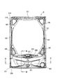
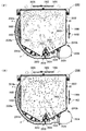
手段12:手段11の構成において、
「前記発光手段は、
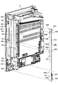
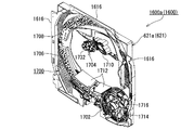
前記演出空間形成部材の外周で左右側及び上側に配置されている」ものであることを特徴とする。
Means 12: In the constitution of
"The light emitting means is
It is arranged on the left and right sides and the upper side on the outer periphery of the production space forming member ”.
ところで、演出空間に対して発光手段を配置する位置としては、種々の位置が考えられるが、例えば、発光手段を演出空間の前側に配置するようにした場合、発光手段からの光が遊技機の後方へ向かって照射されることとなり、演出空間内を浮遊する浮遊体に対して発光手段からの光が順光となり、浮遊体をより見易くすることができる反面、浮遊体の前側に発光手段が配置されるので、遊技者側から浮遊体が見辛くなる恐れがあると共に、発光手段によって演出空間の後側も照らされるので、演出空間の後側に配置された部材が明るくなり、相対的に浮遊体が暗くなって見辛くなったり浮遊体の発光装飾が低下してしまったりする問題がある。 By the way, there are various possible positions for the light emitting means to be arranged with respect to the effect space. For example, when the light emitting means is arranged on the front side of the effect space, the light from the light emitting means is emitted from the gaming machine. The light from the light emitting means is forwarded to the floating body floating in the production space, and the floating body can be made easier to see, while the light emitting means is on the front side of the floating body. Since it is arranged, the floating body may be difficult to see from the player side, and the rear side of the production space is also illuminated by the light emitting means, so the members arranged on the rear side of the production space become brighter and relatively There is a problem that the floating body becomes dark and hard to see or the luminous decoration of the floating body is lowered.
また、発光手段を演出空間の後側に配置するようにした場合、発光手段からの光が前方、つまり、遊技者側へ向かって照射されることとなり、蓋然的に、演出空間内を浮遊する浮遊体が発光手段に対して逆光となるので、浮遊体が見辛くなってしまい、浮遊体による装飾効果が得られなくなる問題がある。 In addition, when the light emitting means is arranged on the rear side of the effect space, the light from the light emitting means is irradiated forward, that is, toward the player side, and thus, the light is likely to float in the effect space. Since the floating body is backlit with respect to the light emitting means, the floating body becomes difficult to see, and there is a problem that the decoration effect by the floating body cannot be obtained.
手段12の構成によると、発光手段を、演出空間形成部材の外周で左右側及び上側に配置したものである。
According to the configuration of the
これにより、演出空間形成部材(演出空間)の左右側や上側の外周に発光手段を配置するようにしているので、発光手段により演出空間内を浮遊する浮遊体が見辛くなるのを防止することができると共に、発光手段からの光が、直接遊技者に照射されて浮遊体が逆光状態となるのを防止したり、演出空間の後側を照射してしまい演出空間の後側が明るくなることで相対的に浮遊体が暗くなって浮遊体が見辛くなるのを防止したりすることができ、浮遊体をより良好な状態で発光装飾させることができ、浮遊体による装飾演出を楽しませて遊技に対する興趣が低下するのを抑制することができる。 Thereby, since the light emitting means is arranged on the left and right sides or the upper outer periphery of the effect space forming member (effect space), it is possible to prevent the floating body floating in the effect space from being difficult to see due to the light emitting means. In addition, the light from the light-emitting means is directly irradiated to the player to prevent the floating body from being backlit, or the rear side of the production space is illuminated and the rear side of the production space becomes brighter. It is possible to prevent the floating body from becoming darker and hard to see, and to make the floating body light up and decorate in a better state. It can suppress that the interest with respect to falls.
また、発光手段を演出空間形成部材の左右側及び上側の外周に配置するようにしているので、演出空間形成部材の下側にスペースを確保することが可能となり、演出空間形成部材の下側に搬送路の一部や、搬送手段(空気流供給手段)等を配置し易くすることができ、上述した作用効果を奏する遊技機をより具現化し易くすることができる。 Further, since the light emitting means is arranged on the left and right sides and the upper outer periphery of the effect space forming member, it is possible to secure a space below the effect space forming member, and on the lower side of the effect space forming member. A part of the conveyance path, conveyance means (air flow supply means), and the like can be easily arranged, and a gaming machine having the above-described effects can be more easily realized.
手段13:手段1から手段12までの何れか一つの構成において、
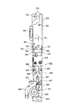
「前記搬送路は、
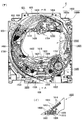
一方の端部側が前記演出空間形成部材により形成される前記演出空間の下部と連通すると共に、他方の端部が前記演出空間形成部材により形成される前記演出空間の上部と連通し、筒状で前記演出空間形成部材の外側に配置される」ものであることを特徴とする。
Means 13: In any one configuration from means 1 to means 12,
“The transport path is
One end portion communicates with a lower portion of the effect space formed by the effect space forming member, and the other end portion communicates with an upper portion of the effect space formed by the effect space forming member. It is arranged on the outside of the effect space forming member ”.
手段13の構成によると、搬送路を、一方の端部側(下部側)が演出空間形成部材の演出空間の下部と連通すると共に、他方の端部(上部側)が演出空間形成部材の演出空間の上部と連通し、筒状で演出空間形成部材の外側に配置するようにしたものである。
According to the configuration of the
これにより、搬送路における一方の端部側で演出空間内の下部に浮遊落下してきた浮遊体を受取ることができると共に、他方の端部から演出空間内の上部に搬送手段によって搬送された浮遊体を供給することができ、浮遊体を搬送するための搬送路を具現化することができると共に、搬送路が筒状とされているので、搬送中の浮遊体が搬送路から外れてしまうのを容易に防止することができ、搬送路から外れた浮遊体により不具合が発生するのを防止することができる。 Accordingly, the floating body that has fallen and dropped to the lower part of the production space on one end side in the conveyance path can be received, and the floating body conveyed by the conveying means from the other end to the upper part of the production space. Since the transport path for transporting the floating body can be embodied and the transport path is cylindrical, the floating body being transported can be removed from the transport path. It can be easily prevented, and it is possible to prevent a problem from occurring due to a floating body that is out of the conveyance path.
また、搬送路を演出空間形成部材の外側に配置しているので、搬送路を演出空間形成部材の内部に配置した場合と比較して、演出空間形成部材によって区画形成される演出空間(演出空間における視認可能範囲)の広さ(大きさ)を相対的に大きくすることが可能となると同時に、相対的に演出空間の視認可能範囲がより広くなることとなり、より広い範囲で浮遊体を浮遊落下させて浮遊体の動きをより複雑なものとしたり、多くの浮遊体を広範囲に浮遊落下させて浮遊体による装飾演出をより目立たせたりすることができ、遊技者を楽しませて遊技に対する興趣が低下するのを抑制することができる。 In addition, since the transport path is arranged outside the effect space forming member, the effect space (effect space) that is partitioned by the effect space forming member as compared with the case where the transport path is arranged inside the effect space forming member. It is possible to relatively increase the size (size) of the visible space at the same time, and at the same time, the visible space of the production space becomes relatively wider. To make the movement of the floating body more complex, or to drop many floating bodies over a wide area and make the decoration production by the floating body more prominent, entertaining the player and having an interest in the game It can suppress that it falls.
更に、搬送路を演出空間形成部材の外側、つまり、浮遊体を演出空間の外側で搬送するようにしているので、搬送手段として空気流等の搬送流を用いるようにした場合、浮遊体を搬送する空気流(搬送流)の強弱により演出空間内の空気(流体)の流れに影響が及ぼされるのを可及的に少なくすることが可能となり、空気流により演出空間内における浮遊体の浮遊が大きく変化するのを抑制することができ、演出空間内で浮遊体を違和感無く確実に浮遊させて上述した演出効果を確実に奏する遊技機とすることができる。 Furthermore, since the transport path is transported outside the effect space forming member, that is, the floating body is transported outside the effect space, when a transport flow such as an air flow is used as the transport means, the float is transported. It is possible to reduce the influence of the air (fluid) flow in the production space as much as possible due to the strength of the air flow (conveyance flow), and the floating of the floating body in the production space is caused by the air flow. It is possible to suppress a large change, and it is possible to provide a gaming machine that reliably achieves the above-described effects by reliably floating the floating body in the effect space without a sense of incongruity.
なお、搬送路における演出空間の下部と連通する一方の端部側とは、搬送路の端部そのものとしても良いし、搬送路の端部から所定範囲内に形成された開口部(例えば、連通口)としても良い。つまり、搬送路は、演出空間の上部側(出口側)が一つなのに対して、演出空間の下部側(入口側)が一つ又は二つとしたものである。 The one end side communicating with the lower part of the production space in the conveyance path may be the end of the conveyance path itself, or an opening (for example, communication) formed within a predetermined range from the end of the conveyance path. Mouth). In other words, the transport path has one or two lower sides (entrance side) of the production space while there is one upper side (exit side) of the production space.
手段14:手段1から手段13までの何れか一つの構成において、
「前記搬送手段は、
前記搬送路内を前記演出空間の下部側から上部側へ向かって流れる搬送流によって、前記浮遊体を搬送する」ものであることを特徴とする。
Means 14: In any one configuration from means 1 to means 13,
“The transport means
The floating body is transported by a transport flow that flows from the lower side to the upper side of the effect space in the transport path.
ここで、「搬送流」としては、「空気(気体)の流れ」、「液体(水)の流れ」、「浮遊体よりも小さい粒子(例えば、粉体)の流れ」、等が挙げられる。 Here, examples of the “conveying flow” include “flow of air (gas)”, “flow of liquid (water)”, “flow of particles (for example, powder) smaller than a floating body”, and the like.
ところで、浮遊体を搬送する搬送手段として、例えば、浮遊体を収容可能な容器を移動させることで浮遊体を搬送させるものや、ベルトコンベアを用いたものとした場合、搬送路内で浮遊体を収容した容器を移動させたり、搬送路内にベルトコンベアを配置したりする必要があり、搬送手段における浮遊体を搬送するための機構が複雑化すると共に、それら機構を配置するためのスペースが多く必要となり、搬送手段が大型化し相対的に演出空間が狭くなる恐れがあると同時に、搬送手段に係るコストが増加する恐れがある。 By the way, as a transport means for transporting the floating body, for example, when the floating body is transported by moving a container that can accommodate the floating body, or using a belt conveyor, the floating body is moved in the transport path. It is necessary to move the containers that are housed, and to place a belt conveyor in the transport path, which complicates the mechanism for transporting the floating body in the transport means and increases the space for placing these mechanisms. This is necessary, and there is a possibility that the transport means becomes large and the effect space becomes relatively narrow, and at the same time, the cost related to the transport means may increase.
手段14の構成によると、搬送手段を、搬送路内を演出空間の下部側から上部側へ向かって流れる搬送流により浮遊体を搬送させるようにしたものである。
According to the configuration of the
これにより、搬送路を流れる搬送流によって浮遊体を搬送させるようにしており、搬送流を発生させる手段(例えば、ファン)と搬送路のみで浮遊体を搬送することができるので、搬送手段に係る構成を簡略化して小型化することが可能となり、相対的に演出空間が狭くなるのを防止して演出空間を可及的に広くすることができると同時に、相対的に演出空間における視認可能範囲を広くすることができ、広い範囲で浮遊する浮遊体を遊技者に見せて遊技者に与えるインパクトを高くすることができると共に、浮遊体の浮遊する動きを楽しませて遊技に対する興趣が低下するのを抑制することができる。 Accordingly, the floating body is transported by the transport flow flowing through the transport path, and the floating body can be transported only by the means (for example, a fan) that generates the transport flow and the transport path. The structure can be simplified and downsized, the production space can be made as wide as possible by preventing the production space from becoming relatively narrow, and at the same time, the viewable range in the production space is relatively large It is possible to increase the impact on the player by showing floating bodies floating in a wide range to the player, and at the same time entertaining the floating movement of the floating bodies and reducing the interest in games Can be suppressed.
また、搬送流によって浮遊体を搬送するようにしているので、搬送路を浮遊体が通過可能な単なる筒状のものとするだけで良く、搬送路を簡単に構成することができる。 In addition, since the floating body is transported by the transport flow, it is only necessary to make the transportation path a simple cylinder through which the floating body can pass, and the transportation path can be configured easily.
更に、搬送流によって浮遊体を搬送するようにしているので、搬送路を流れる搬送流により搬送路内の流体圧(例えば、気圧)が、演出空間内の流体圧(例えば、気圧)よりも低くなり、演出空間内の下部で搬送路と連通する部位において演出空間内の流体が搬送路内へ吸込まれることとなり、この流体の流れによって演出空間の下部へ浮遊落下した浮遊体を搬送路内へと吸込むことができ、浮遊落下した浮遊体を確実に収集して搬送路内へ受渡すことができると共に、搬送路を通して演出空間の下部から上部へ浮遊体を確実に搬送することができる。 Furthermore, since the floating body is conveyed by the conveyance flow, the fluid pressure (for example, atmospheric pressure) in the conveyance path is lower than the fluid pressure (for example, atmospheric pressure) in the effect space due to the conveyance flow flowing through the conveyance path. Therefore, the fluid in the production space is sucked into the conveyance path at the part communicating with the conveyance path in the lower part of the production space, and the floating body suspended and dropped to the lower part of the production space by the flow of the fluid in the conveyance path. The floating body that has fallen and dropped can be reliably collected and delivered to the conveyance path, and the floating body can be reliably conveyed from the lower part to the upper part of the effect space through the conveyance path.
なお、搬送流として、空気流を用いるようにしても良く、これにより、搬送流として液体や粉体を用いた場合と比較して、演出空間内に搬送流の媒体が進入しても問題が発生するのを可及的に小さくすることができると共に、搬送流から浮遊体を容易に分離させることが可能となり、仮に浮遊体に搬送流の媒体である空気が付着しても問題となることが無く、演出空間内で浮遊体を良好に浮遊させて所望の演出効果を確実に得ることができる。 Note that an air flow may be used as the transport flow, which causes a problem even if a medium of the transport flow enters the effect space, compared to the case where liquid or powder is used as the transport flow. It is possible to reduce the generation as much as possible, and it is possible to easily separate the floating body from the transport flow, and even if air as a medium of the transport flow adheres to the floating body, there is a problem. Therefore, it is possible to satisfactorily obtain a desired effect by floating the floating body well in the effect space.
また、搬送路内へ搬送流を供給する部位に、搬送流が通過可能とされると共に浮遊体が通過不能とされた逆流防止部材を配置するようにしても良く、これにより、演出空間形成部材における演出空間の下部から搬送路側へ受渡された浮遊体が、搬送流を供給する手段
(例えば、空気流供給手段)側へ移動するのを防止することができるので、何らかの理由により浮遊体が搬送路の上流側へ移動してしまって不具合が発生するのを防止することができる。なお、「逆流防止部材」としては、「板状の部材に複数の貫通孔が形成されたもの」、「網状のもの」、等を例示することができ、複数の貫通孔が形成された板状部材として、パンチングメタルを用いることが望ましく、これにより、樹脂部材を用いた場合と比較して、逆流防止部材の剛性(強度)を同一とするとより多くの貫通孔を形成することが可能となり、より多くの搬送流(空気流)を搬送路へ供給することができ、浮遊体を確実に搬送させることができる。
In addition, a backflow prevention member that can pass the transport flow and cannot pass the floating body may be disposed in a portion that supplies the transport flow into the transport path, thereby providing a production space forming member. The floating body delivered from the lower part of the production space to the conveyance path side can be prevented from moving to the means for supplying the conveyance flow (for example, the air flow supply means), so that the floating body is conveyed for some reason. It is possible to prevent a problem from occurring due to the movement to the upstream side of the road. Examples of the “backflow prevention member” include “a plate-like member formed with a plurality of through holes”, “a net-like member”, and the like, and a plate formed with a plurality of through holes. It is desirable to use a punching metal as the shape member, which makes it possible to form more through holes when the backflow prevention member has the same rigidity (strength) compared to the case of using a resin member. More transport flow (air flow) can be supplied to the transport path, and the floating body can be transported reliably.
手段15:手段14の構成において、
「前記搬送手段は、
前記搬送路における一方の端部から他方の端部へ向かって流れる搬送流としての空気流を供給可能な空気流供給手段を有している」ものであることを特徴とする。
Means 15: In the configuration of
“The transport means
It has an air flow supply means capable of supplying an air flow as a transport flow flowing from one end portion to the other end portion of the transport path ”.
ここで、「空気流供給手段」としては、「シロッコファンを備えたもの」、「プロペラファンを備えたもの」、「ピストンを備えたもの」、「圧縮空気を生成可能なコンプレッサとタンクを備えたもの」、等が挙げられる。 Here, as "air flow supply means", "equipped with a sirocco fan", "equipped with a propeller fan", "equipped with a piston", "equipped with a compressor and a tank capable of generating compressed air" Etc. ".
手段15の構成によると、搬送手段に、搬送路における一方の端部から他方の端部へ向かって流れる搬送流としての空気流を供給可能な空気流供給手段を備えるようにしたものである。
According to the configuration of the
これにより、搬送路における一方の端部から搬送路内へ搬送流としての空気流を供給するようにしているので、この空気流により搬送路内の気圧が、演出空間内の気圧よりも低くなって、一方の端部側で演出空間の下部と連通した部分(連通口)を通して演出空間内の空気が搬送路内へ吸込まれることとなり、この空気の流れによって演出空間の下部へ浮遊落下した浮遊体を搬送路内へと吸込むことができ、浮遊落下した浮遊体を確実に収集して搬送路内へ受渡すことができると共に、搬送路を通して演出空間の下部から上部へ浮遊体を確実に搬送することができる。なお、一方の端部側で演出空間の下部と連通した部分(連通口)の開口する方向を、搬送路内での空気流の流れる方向(搬送路の軸方向)に対して略直交する方向とすることが望ましく、これにより、上述した吸込み効果を確実に発揮させることができると共に、一方の端部側で演出空間の下部と連通した部分(連通口)を介して空気流が演出空間内へ流入することで浮遊体の浮遊落下を妨げてしまうのを防止することができる。 As a result, an air flow as a transport flow is supplied from one end of the transport path into the transport path, so that the air pressure in the transport path is lower than the atmospheric pressure in the effect space. Then, air in the production space is sucked into the conveyance path through a portion (communication port) communicating with the lower part of the production space on one end side, and the air flow floated and dropped to the lower part of the production space. Floating bodies can be sucked into the conveyance path, and floating bodies that have fallen and dropped can be reliably collected and delivered to the conveyance path, and the floating bodies can be reliably transferred from the bottom to the top of the production space through the conveyance path. Can be transported. Note that the direction in which the portion (communication port) that communicates with the lower portion of the production space on one end side opens is substantially perpendicular to the direction in which the airflow flows in the conveyance path (axial direction of the conveyance path). In this way, the above-described suction effect can be surely exerted, and the airflow is generated in the production space through a portion (communication port) communicating with the lower part of the production space on one end side. It is possible to prevent the floating body from being hampered by falling into the water.
また、搬送路内を流れる空気流により浮遊体を搬送するようにしているので、浮遊体を液体や粉体等の流体を用いて搬送させた場合と比較して、演出空間内に空気流が進入しても問題が発生するのを可及的に小さくすることができると共に、空気流から浮遊体を容易に分離させることが可能となり、仮に浮遊体に空気流の空気が付着しても問題となることが無く、演出空間内で浮遊体を良好に浮遊させて所望の発光装飾効果を確実に得ることができる。 In addition, since the floating body is transported by the air flow flowing in the transport path, compared to the case where the floating body is transported using a fluid such as liquid or powder, the air flow is generated in the effect space. It is possible to minimize the occurrence of problems even when entering, and it is possible to easily separate the floating body from the air flow, and even if air in the air flow adheres to the floating body, there is a problem. Therefore, it is possible to satisfactorily float the floating body in the production space and reliably obtain a desired light emitting decoration effect.
また、浮遊体を、空気流供給手段から供給される空気流により搬送するようにしているので、空気流の強さが最低限浮遊体を搬送可能な強さであれば良く、空気流を発生させるモータ等の制御を緻密に行う必要が無く、安価な制御を用いることができ遊技機に係るコストが増加するのを抑制することができる。 In addition, since the floating body is transported by the air flow supplied from the air flow supply means, it is sufficient that the strength of the air flow is at least that which can transport the floating body, and the air flow is generated. Therefore, it is not necessary to precisely control the motor to be used, and it is possible to use inexpensive control and suppress an increase in the cost of the gaming machine.
なお、演出空間形成部材の上部に、空気が通過可能とされると共に浮遊体が通過不能とされた複数の孔を有する排気部材を配置するようにすることが望ましく、これにより、搬送路を通って演出空間内へ放出された空気流を、演出空間形成部材の上部から演出空間形成部材(演出空間)の外部へ排出することができ、搬送路内で空気流が滞るのを防止して空気流により浮遊体を確実に搬送させることができる。また、搬送路を通って演出空間内へ放出された空気流のみを演出空間形成部材(演出空間)の外部へ排出して空気流により搬送された浮遊体を演出空間内に留めることができ、演出空間形成部材の外側へ出た浮遊体によって不具合が発生するのを防止することができると共に、演出空間内の浮遊体が減少して浮遊体による演出効果が得られなくなるのを防止することができる。 In addition, it is desirable to arrange an exhaust member having a plurality of holes in which air is allowed to pass and floating bodies are not allowed to pass above the production space forming member. The air flow released into the production space can be discharged from the upper part of the production space forming member to the outside of the production space forming member (production space), and air is prevented from stagnation in the conveyance path. The floating body can be reliably conveyed by the flow. In addition, only the air flow released into the production space through the conveyance path can be discharged to the outside of the production space forming member (production space) and the floating body conveyed by the air flow can be retained in the production space. It is possible to prevent problems from occurring due to the floating body that has moved outside the production space forming member, and to prevent the floating body in the production space from being reduced and the production effect due to the floating body from being lost. it can.
手段16:手段1から手段15までの何れか一つの構成において、
「前記演出空間形成部材の上部に配置され、空気が通過可能とされると共に前記浮遊体が通過不能とされた複数の孔を有し、前記演出空間形成部材によって形成される前記演出空間を大気解放する排気部材を更に具備する」ものであることを特徴とする。
Means 16: In any one configuration from means 1 to means 15,
“The effect space formed by the effect space forming member is arranged in the atmosphere, having a plurality of holes that are arranged above the effect space forming member and allow air to pass therethrough and not allow the floating body to pass through. It further comprises an exhaust member to be released ".
ここで、排気部材における「複数の孔」としては、「板状の部材に対して複数の貫通孔が形成されたもの」、「網状に形成されたもの」、「繊維が絡まった不織布状のもの」、等が挙げられる。 Here, as the “plurality of holes” in the exhaust member, “one in which a plurality of through holes are formed in a plate-like member”, “one in a net shape”, “a nonwoven fabric in which fibers are entangled” Thing ", etc. are mentioned.
ところで、空気流によって演出空間の上部に浮遊体を搬送するようにした場合、空気流から浮遊体を分離させる方法として、例えば、搬送路の開口から放出された空気流が複数の抵抗体と接触するようにして空気流の勢いを弱めることで、浮遊体がその自重により空気流から分離するようにしたり、或いは、演出空間における上部の空間を、空気流が浮遊体を搬送不能となる程度に減衰させることが可能な大きさとすることで、自然に浮遊体が空気流から分離するようにしたりすることが考えられる。しかしながら、上述したような方法では、演出空間内で空気流を減衰させるための広い空間が必要となるので、演出空間内における浮遊体が浮遊落下する領域が相対的に小さくなり、浮遊体の浮遊を充分に楽しませることが困難となる恐れがある。 By the way, when the floating body is transported to the upper part of the production space by the air flow, as a method of separating the floating body from the air flow, for example, the air flow discharged from the opening of the transport path contacts a plurality of resistors. In this way, by reducing the momentum of the airflow, the floating body can be separated from the airflow by its own weight, or the upper space in the production space can be prevented from being carried by the airflow. It is conceivable that the floating body naturally separates from the air flow by setting the size so that it can be attenuated. However, the above-described method requires a wide space for attenuating the air flow in the effect space, so that the area in which the floating object floats and falls in the effect space becomes relatively small, and the floating object floats. May be difficult to fully enjoy.
手段16の構成によると、遊技機に、演出空間形成部材の上部に配置され、空気が通過可能とされると共に浮遊体が通過不能とされた複数の孔を有し、演出空間形成部材によって形成される演出空間を大気解放する排気部材を更に備えるようにしたものである。
According to the configuration of the
これにより、排気部材によって演出空間内が大気解放されているので、演出空間内の空気が自由に移動(出入)することが可能となり、演出空間内での浮遊体の浮遊落下をより自然な感じとすることができ、浮遊体の動きに対して遊技者に違和感を与えて興趣を低下させてしまうのを抑制することができる。 As a result, the air inside the production space is released to the atmosphere by the exhaust member, so the air in the production space can freely move (in and out), and the floating fall of the floating body in the production space feels more natural. It is possible to prevent the player from feeling uncomfortable with the movement of the floating body and reducing the interest.
なお、搬送路内へ空気流供給手段から供給される空気流によって浮遊体を搬送させるようにした場合、搬送路における他方の端部から浮遊体と伴に放出される空気流を大気解放された演出空間形成部材の上部から排気部材を通して演出空間形成部材(演出空間)の外部へ排出することができ、搬送路内で空気流が滞るのを防止して空気流により浮遊体を確実に搬送させることができる。また、搬送路を通って搬送路における他方の端部から演出空間内へ放出された空気流のみを演出空間形成部材(演出空間)の外部へ排出して空気流により搬送された浮遊体を演出空間内に留めることができ、演出空間形成部材の外側へ出た浮遊体によって不具合が発生するのを防止することができると共に、空気流を減衰させるための抵抗体や空間を備える必要が無く、相対的に演出空間を広くすることができるので、より広い範囲で浮遊体を浮遊させることができ、遊技者を楽しませて遊技に対する興趣が低下するのを抑制することができる。更に、排気部材により空気流から浮遊体を演出空間側へ分離させることができるので、搬送路を流れる空気流の強さを、浮遊体が確実に搬送される充分以上の強さの空気流としても、排気部材によって浮遊体を確実に分離させることができる。つまり、搬送路を通して浮遊体を確実に搬送することができるので、搬送路上で浮遊体が滞るのを防止することが可能となり、演出空間内の上部へ浮遊体を搬送して浮遊体を確実に浮遊させることができ、浮遊体による装飾演出効果を確実に発揮させて遊技者の遊技に対する興趣が低下するのを抑制することができる。 When the floating body is transported by the air flow supplied from the air flow supply means into the transport path, the air flow released along with the floating body from the other end of the transport path is released to the atmosphere. It can be discharged from the upper part of the production space forming member to the outside of the production space forming member (production space) through the exhaust member, and the air flow is prevented from stagnation in the conveyance path and the floating body is reliably conveyed by the air flow. be able to. In addition, only the air flow released from the other end of the transport path into the effect space through the transport path is discharged to the outside of the effect space forming member (effect space) to produce a floating body conveyed by the air flow. It can be kept in the space, it is possible to prevent the occurrence of problems due to the floating body that has gone out of the production space forming member, and there is no need to provide a resistor or space for attenuating the air flow, Since the production space can be relatively widened, the floating body can be floated in a wider range, and it is possible to suppress the interest of the game from deteriorating by making the player entertained. Furthermore, since the floating member can be separated from the air flow to the effect space side by the exhaust member, the strength of the air flow flowing through the conveyance path is set to an air flow having a strength that is more than sufficient to ensure that the floating member is conveyed. In addition, the floating body can be reliably separated by the exhaust member. In other words, since the floating body can be reliably transported through the transport path, it is possible to prevent the floating body from stagnation on the transport path, and the floating body is securely transported to the upper part of the production space. It is possible to float, and it is possible to reliably exhibit the decoration effect by the floating body and to prevent the player's interest in the game from decreasing.
手段17:手段16の構成において、
「前記搬送路は、
前記演出空間の上部に前記浮遊体と共に搬送放出される前記搬送流の流れる方向が、前記排気部材に対して斜めに交差する方向となるように形成されている」ものであることを特徴とする。
Means 17: In the configuration of
“The transport path is
The direction of the transport flow transported and discharged together with the floating body is formed in the upper part of the effect space so as to be a direction obliquely intersecting the exhaust member. .
ところで、搬送路を介して演出空間内へ誘導放出される搬送流(空気流)が演出空間内の左右方向へ流れようにした場合、搬送流が流入する側とは反対側の側部に搬送流が当り、側部に当った搬送流は側部に沿って上側と下側に分かれて流れることとなるが、その流れに従って浮遊体も搬送されるので、下側へ分かれた搬送流に乗った浮遊体は、演出空間内を浮遊することなく下方へ送られてしまい、また、上側へ分かれた搬送流に乗った浮遊体は、上側へ舞い上げられて演出空間内を落下し難くなり、而して、演出空間内で浮遊体を良好な状態で浮遊落下させることができなくなる恐れがある。 By the way, when the conveyance flow (air flow) guided and released into the production space through the conveyance path is made to flow in the left-right direction in the production space, it is conveyed to the side opposite to the side where the conveyance flow flows in. The flow that hits the side and hits the side part is divided into an upper side and a lower side along the side part. The floating body will be sent downward without floating in the production space, and the floating body riding on the transport flow divided upward will be lifted up and difficult to fall in the production space, Thus, there is a fear that the floating body cannot be suspended and dropped in a good state in the production space.
また、演出空間形成部材の上部に排気部材が配置された状態で、搬送路から放出される搬送流が排気部材に対して略直交する方向へ流れるようにした場合、排気部材(排気部材の下面)と当接した浮遊体は排気部材を通過することができないので、排気部材から演出空間を落下しようとするが、下方から放出される搬送流によって排気部材側へ押し付けられて張り付いてしまい、演出空間で落下することができなくなると共に、排気部材に張り付いた浮遊体によって、排気部材に形成された孔が塞がれてしまい、搬送流を排出することができなくなる問題が発生する。 In addition, in the state where the exhaust member is arranged on the upper portion of the effect space forming member, when the transport flow discharged from the transport path is made to flow in a direction substantially orthogonal to the exhaust member, the exhaust member (the lower surface of the exhaust member) ) And the floating body in contact with the exhaust member cannot pass through the exhaust member, so it tries to drop the production space from the exhaust member, but it is pushed and stuck to the exhaust member side by the carrier flow released from below, In addition to being unable to fall in the production space, a hole formed in the exhaust member is blocked by the floating body attached to the exhaust member, and the conveyance flow cannot be discharged.
手段17の構成によると、搬送路を、演出空間の上部に浮遊体と共に搬送放出される搬送流の流れる方向が、排気部材に対して斜めに交差する方向となるように形成したものである。
According to the configuration of the
これにより、搬送路から演出空間内へ放出される搬送流の流れる方向を、排気部材に対して斜めに交差する方向としているので、排気部材に当接する浮遊体に対し横方向の力を作用させることができ、搬送流によって浮遊体が排気部材に押し付けられ難くなり排気部材に張り付くのを防止することができる。また、排気部材が浮遊体によって塞がれてしまうのを防止することができるので、搬送流を確実に演出空間外へ排出することができ、搬送路を通って搬送流により演出空間の上部へ搬送された浮遊体を、演出空間内で浮遊落下させて上述した作用効果を確実に奏する遊技機とすることができる。 As a result, the direction in which the transport flow discharged from the transport path into the effect space flows is a direction that obliquely intersects the exhaust member, so that a lateral force is applied to the floating body in contact with the exhaust member. It is possible to prevent the floating body from being pressed against the exhaust member by the transport flow and sticking to the exhaust member. In addition, since the exhaust member can be prevented from being blocked by the floating body, the transport flow can be surely discharged out of the effect space, and the transport flow passes through the transport path to the upper part of the effect space. The transported floating body can be suspended and dropped in the effect space to provide a gaming machine that reliably exhibits the above-described effects.
手段18:手段1から手段17までの何れか一つの構成において、
「前記演出空間内の下部から上部へ向かって流れる拡散流を供給することで、前記搬送手段により前記演出空間内の上部へ搬送された前記浮遊体を前記演出空間内で拡散浮遊させる拡散浮遊手段を更に具備する」ものであることを特徴とする。
Means 18: In any one configuration from means 1 to means 17,
“Diffusion floating means for diffusing and floating the floating body conveyed to the upper part in the effect space by the conveying means by supplying a diffusion flow flowing from the lower part to the upper part in the effect space. It is further equipped with ".
ここで、拡散流を供給する方向としては、「演出空間内を浮遊落下する浮遊体が演出空間内で拡散される方向」、「演出空間内における上部全体の方向」、「搬送路を通って演出空間内へ搬送供給される浮遊体の供給位置へ向かう方向」、「演出空間形成部材の上部を覆う排気部材における搬送路の開口から放出される空気流が最も多く排出される位置へ向かう方向」、等が挙げられる。 Here, the direction of supplying the diffusion flow is “the direction in which the floating body that floats and falls in the production space is diffused in the production space”, “the direction of the entire upper part in the production space”, “through the conveyance path” "Direction toward the supply position of the floating body transported and supplied into the effect space", "Direction toward the position where the airflow discharged from the opening of the conveyance path in the exhaust member covering the upper part of the effect space forming member is discharged most And the like.
ところで、浮遊落下する浮遊体を演出空間内で広く拡散させる構成(拡散浮遊手段)としては、例えば、演出空間内における浮遊体が搬送供給される位置に、浮遊体と当接可能な当接体を複数設け、浮遊体が当接体と当接することで浮遊体の落下位置を変化させて浮遊体を拡散浮遊させるようにすることが考えられる。しかしながら、この場合、落下する浮遊体をより広く拡散させるようにするためには、当接体を上下方向に多く配置する必要があり、浮遊体を拡散させるための空間(当接体が配置される空間)が大きくなり、相対的に、浮遊体が自由に浮遊落下する空間(演出空間)が狭くなる問題がある。 By the way, as a structure (diffusion floating means) which diffuses the floating body that floats and falls widely in the production space, for example, a contact body that can come into contact with the floating body at a position where the floating body is transported and supplied in the production space. It is considered that the floating body is diffused and floated by changing the position where the floating body falls by bringing the floating body into contact with the contact body. However, in this case, in order to spread the falling floating body more widely, it is necessary to arrange a large number of abutting bodies in the vertical direction, and a space for diffusing the floating bodies (the abutting bodies are arranged). There is a problem that the space (direction space) in which the floating body freely floats and falls is relatively narrow.
手段18の構成によると、遊技機に、演出空間内の下部から上部へ向かって流れる拡散流を供給することで、搬送手段により演出空間内の上部へ搬送された浮遊体を演出空間内で拡散浮遊させる拡散浮遊手段を更に備えるようにしたものである。
According to the configuration of the
これにより、演出空間内の上部へ搬送供給された浮遊体が拡散浮遊手段による拡散流によって、演出空間内へ広く拡散されるので、浮遊体が演出空間内の偏った位置で浮遊することで浮遊体による演出効果が低下してしまうのを防止することが可能となり、演出空間(演出空間における視認可能範囲)内の広い範囲で浮遊体を浮遊させて、浮遊体の浮遊による演出効果を高めることができ、多彩な演出により遊技者を楽しませて遊技に対する興趣が低下するのを抑制することができる。 Thereby, the floating body transported and supplied to the upper part in the production space is diffused widely in the production space by the diffusion flow by the diffusion floating means, so that the floating body floats by floating at a biased position in the production space. It is possible to prevent the presentation effect due to the body from being lowered, and float the floating body in a wide range within the production space (visible range in the production space), thereby enhancing the presentation effect due to the floating of the floating body It is possible to entertain the player with a variety of effects, and to suppress a decrease in interest in the game.
また、拡散流を下側から供給するようにしているので、演出空間の上部へ供給された浮遊体に拡散流が当ることで、容易に浮遊体を演出空間内で拡散させることができると共に、浮遊体が浮遊落下へ移動する速度を遅くして浮遊時間を長くすることができ、演出空間内を浮遊する浮遊体の動きをより楽しませて遊技者の興趣が低下するのを抑制することができる。 In addition, since the diffusion flow is supplied from the lower side, the diffusion flow hits the floating body supplied to the upper part of the production space, so that the floating body can be easily diffused in the production space, It can slow down the speed at which the floating body moves to the floating fall and lengthen the floating time, making the movement of the floating body floating in the production space more enjoyable and preventing the player's interest from deteriorating it can.
更に、拡散流により浮遊体を拡散させるようにしているので、拡散浮遊手段としての当接体に当接させて浮遊体を拡散させるようにした場合と比較して、演出空間内に複数の当接体を配置する必要が無く演出空間内で当接体が見えることで演出空間内の見栄えが悪くなるのを防止することができると共に、狭い範囲でも浮遊体をより広範囲に拡散させることができ、演出空間内で一面に広がった浮遊体の浮遊を遊技者に楽しませて遊技に対する興趣が低下するのを抑制することができる。 Furthermore, since the floating body is diffused by the diffusion flow, a plurality of hits are produced in the production space as compared with the case where the floating body is diffused by contacting the contact body as the diffusion floating means. It is possible to prevent the appearance of the production space from deteriorating by seeing the contact body in the production space without the need to arrange the contact body, and to spread the floating body in a narrow range more widely. It is possible to make the player enjoy the floating of the floating body spreading all over in the production space, and to prevent the interest in the game from being lowered.
また、拡散浮遊手段によって浮遊体を狭い範囲で容易に拡散させることができるので、演出空間の上部における前側遮蔽部材によって遮蔽される範囲を小さくすることが可能となり、相対的に演出空間における遊技者側からの視認可能範囲を広くすることができ、より広い範囲で浮遊落下する浮遊体を遊技者に見せて浮遊体による装飾演出をより楽しませることができると共に、演出空間における視認可能範囲が広くなるので、演出空間(演出空間内の浮遊体)をより目立たせてインパクトを高めることができ、遊技者の関心を強く引き付けられる遊技機とすることができる。 In addition, since the floating body can be easily diffused in a narrow range by the diffusion floating means, it is possible to reduce the range shielded by the front shielding member in the upper part of the production space, and the player in the production space relatively The visible range from the side can be widened, the floating body that floats and falls in a wider range can be shown to the player, and the decoration production by the floating body can be more enjoyed, and the visible range in the production space is wide Therefore, the effect space (floating body in the effect space) can be made more conspicuous, the impact can be increased, and a gaming machine that can attract the player's interest can be obtained.
なお、搬送手段で搬送流を発生させる手段(例えば、空気流供給手段、ファン)によって拡散流を発生させるようにしても良く、これにより、拡散流と搬送流を同一の発生源とすることで構成を簡略化することができ、遊技機に係るコストが増加するのを抑制することができる。 It should be noted that the diffusion flow may be generated by means (for example, an air flow supply means, a fan) that generates the conveyance flow by the conveyance means, thereby making the diffusion flow and the conveyance flow the same source. A structure can be simplified and it can suppress that the cost which concerns on a game machine increases.
手段19:手段18の構成において、
「前記拡散浮遊手段は、
前記搬送手段における前記空気流供給手段から供給される前記空気流の一部を拡散流として用いる」ものであることを特徴とする。
Means 19: In the constitution of
"The diffusion floating means is
"A part of the air flow supplied from the air flow supply means in the transport means is used as a diffusion flow".
手段19の構成によると、拡散浮遊手段における拡散流を、搬送手段における空気流供給手段から供給される空気流の一部を拡散流として用いるようにしたものである。
According to the configuration of the
これにより、空気流供給手段から供給される空気流によって、浮遊体を搬送路内で搬送させると共に、演出空間の上部に搬送供給された浮遊体を演出空間内へ拡散浮遊させるようにしているので、拡散浮遊手段において拡散流を供給するための手段(例えば、ファン)を別途備える必要がなく、遊技機に係る構成を簡略化することができ、コストが増加するのを抑制することができると共に、拡散浮遊手段に係るスペースが大きくなるのを抑制することができ、相対的に演出空間を広くすることが可能となると同時に、相対的に演出空間における視認可能範囲を広くすることが可能となり、広い範囲で浮遊する浮遊体を遊技者に見せて遊技者の関心を強く引き付けられるものとすることができる。 Thereby, the floating body is transported in the transport path by the air flow supplied from the air flow supply means, and the floating body transported and supplied to the upper part of the effect space is diffused and suspended in the effect space. In addition, it is not necessary to separately provide a means (for example, a fan) for supplying a diffusion flow in the diffusion floating means, the configuration relating to the gaming machine can be simplified, and an increase in cost can be suppressed. In addition, it is possible to suppress an increase in the space related to the diffusion floating means, it is possible to relatively widen the production space, and at the same time, it is possible to relatively widen the visible range in the production space, A floating body that floats in a wide range can be shown to the player, and the player's interest can be strongly attracted.
手段20:手段1から手段19までの何れか一つの構成において、
「前記演出空間形成部材は、
前記搬送手段側と連通し前記浮遊体が通過可能とされた連通口が形成され、該連通口へ向かって低くなるように傾斜した底部と、
該底部の左右両端から上方へ夫々延出すると共に、何れか一方の上部に前記搬送手段側と連通し前記浮遊体が通過可能な開口が形成された一対の側部と、
該側部の上端同士を連結するように結ぶ天部と、
該天部、一対の前記側部、及び前記底部によって形成される枠の前側及び後側を閉鎖する板状の前部及び後部とを備え、
前記底部、一対の前記側部、前記天部、前記前部、及び前記後部とで前記演出空間を区画形成する」ものであることを特徴とする。
Means 20: In any one configuration from means 1 to means 19,
"The production space forming member is
A communication port that communicates with the conveying means side and allows the floating body to pass therethrough, and a bottom portion that is inclined so as to become lower toward the communication port;
A pair of side portions each extending upward from the left and right ends of the bottom portion, and having an opening formed on one of the upper portions thereof so as to communicate with the conveying means side and allow the floating body to pass through;
A top part that connects the upper ends of the side parts to each other;
A plate-shaped front part and a rear part for closing the front side and the rear side of the frame formed by the top part, the pair of side parts, and the bottom part;
The production space is defined by the bottom portion, the pair of side portions, the top portion, the front portion, and the rear portion.
ところで、演出空間の下部と上部とを連絡する搬送路において、演出空間の上部側として演出空間形成部材の上部(天部)と連通するようにした場合、搬送路が演出空間形成部材の下側から上側まで回り込むように延びる必要があるので、搬送路の長さが長くなり、遊技機における搬送路の占める割合が多くなって相対的に演出空間が狭くなってしまう恐れがある。また、搬送路の上部側を演出空間形成部材の天部と連通するようにした場合、蓋然的に、搬送路の開口方向(開口における搬送路の軸方向)が演出空間の下方を向いた方向となるので、搬送路から搬送された浮遊体が直ちに下方へ向かって落下することとなり、演出空間内で浮遊体が拡散され難くなる恐れがある。また、搬送流(例えば、空気流)を用いて浮遊体を搬送させるようにした場合、搬送路から放出される搬送流が演出空間の下方へ向かって放出されこととなり、その搬送流によって搬送された浮遊体が、搬送流と共に演出空間の上部から下部へ向かって流れて(速く移動して)しまい演出空間を浮遊し難くなって、浮遊体による演出効果が得られなくなる恐れがある。 By the way, in the conveyance path that connects the lower part and the upper part of the production space, when the upper part (the top) of the production space forming member is communicated as the upper part of the production space, the conveyance path is below the production space forming member. Therefore, there is a possibility that the length of the conveyance path becomes long and the proportion of the conveyance path in the gaming machine increases and the effect space becomes relatively narrow. In addition, when the upper side of the conveyance path communicates with the top of the effect space forming member, the direction in which the opening direction of the conveyance path (the axial direction of the conveyance path in the opening) is directed downward of the effect space Therefore, the floating body transported from the transport path immediately falls downward, and the floating body may not be easily diffused in the effect space. Further, when the floating body is transported using a transport flow (for example, an air flow), the transport flow discharged from the transport path is discharged downward in the effect space, and is transported by the transport flow. The floating body flows from the upper part to the lower part of the effect space together with the transport flow (moves quickly), making it difficult to float in the effect space, and there is a possibility that the effect of the floating object cannot be obtained.
手段20の構成によると、演出空間形成部材に、搬送手段側と連通し浮遊体が通過可能な連通口が形成されその連通口へ向かって低くなるように傾斜した底部と、底部の左右両端から上方へ夫々延出すると共に、何れか一方の上部に搬送手段側と連通し浮遊体が通過可能な開口が形成された一対の側部と、側部の上端同士を連結するように結ぶ天部と、天部、一対の側部、及び底部によって形成される枠の前側及び後側を閉鎖する板状の前部及び後部とを備え、底部、一対の側部、天部、前部、及び後部とで演出空間を区画形成するようにしたものである。
According to the configuration of the
これにより、演出空間を内部に区画形成する演出空間形成部材の底部が連通口へ向かって低くなるように傾斜しており、演出空間内を浮遊落下してきた浮遊体が傾斜した底部によって連通口へと案内されて浮遊体を収集することができると共に、連通口を通って浮遊体を搬送路内へ受渡すことができる。そして、連通口を介して搬送路内に受渡された浮遊体は、搬送路内の搬送流に搬送されて演出空間形成部材における一方の側部の開口から再び演出空間内へと供給されて演出空間内を浮遊することができ、浮遊体が浮遊可能な演出空間を形成する演出空間形成部材を良好に具現化することができる。 Thereby, the bottom part of the production space forming member that partitions the production space into the inside is inclined so as to become lower toward the communication port, and the floating body that floats and falls in the production space is inclined to the communication port by the inclined bottom part. The floating body can be collected by being guided, and the floating body can be delivered to the conveyance path through the communication port. Then, the floating body delivered into the conveyance path through the communication port is conveyed to the conveyance flow in the conveyance path and supplied again into the effect space from the opening on one side of the effect space forming member. An effect space forming member that can float in the space and forms an effect space in which the floating body can float can be well realized.
また、演出空間形成部材における側面を形成する側部に備えられた開口を通して、搬送路内を搬送された浮遊体が演出空間内へ搬送供給されるので、例えば、搬送路の上部側を演出空間形成部材の天部と連通するようにした場合と比較して、搬送路の長さを短くすることが可能となり、遊技機における搬送路の占める割合を少なくして相対的に演出空間を広くすることができと同時に、演出空間における視認可能範囲を広くすることができ、広い範囲で浮遊する浮遊体を遊技者に見せて遊技者を楽しませることができる。 In addition, the floating body transported in the transport path is transported and supplied into the effect space through the opening provided in the side portion that forms the side surface of the effect space forming member. Compared to the case where the top of the forming member communicates, the length of the conveyance path can be shortened, and the proportion of the conveyance path in the gaming machine is reduced to relatively widen the production space. At the same time, the viewable range in the production space can be widened, and the player can be entertained by showing the floating body floating in a wide range to the player.
更に、搬送路の上部側を演出空間形成部材における側部に備えられた開口と連通するようにしており、開口の開口方向(開口における搬送路の軸方向)を上下方向に対して交差する方向へ向けることが可能となり、例えば、水平方向から上方向へ向けることで搬送路内を搬送された浮遊体が演出空間の下方へ向かって放出されるのを防止することが可能となり、浮遊体の落下速度が速くなるのを防止して演出空間内で浮遊体を違和感無く浮遊落下させることができ、浮遊体の動きを楽しませて遊技者の興趣が低下するのを抑制することができる。 Furthermore, the upper side of the conveyance path communicates with the opening provided in the side portion of the effect space forming member, and the direction in which the opening direction of the opening (the axial direction of the conveyance path in the opening) intersects the vertical direction For example, it is possible to prevent the floating body transported in the transport path from being released from the horizontal direction to the upward direction, and to be released downward in the production space. It is possible to prevent the falling speed from being increased and to cause the floating body to float and fall in the production space without a sense of incongruity, and to prevent the player's interest from deteriorating by enjoying the movement of the floating body.
なお、演出空間形成部材の天部を大気解放可能としても良く、これにより、演出空間内の空気が自由に移動することができるので、演出空間内での浮遊体の浮遊落下をより自然な感じとすることができ、浮遊体の動きに対して遊技者に違和感を与えて興趣を低下させてしまうのを抑制することができる。また、搬送手段による搬送流を演出空間形成部材の天部から排出することが可能となるので、搬送流が滞るのを防止して搬送流を良好な状態で流すことができ、搬送流により浮遊体を確実に搬送させることができる。 The top of the production space forming member may be open to the atmosphere so that the air in the production space can move freely, so that the floating fall of the floating body in the production space feels more natural. It is possible to prevent the player from feeling uncomfortable with the movement of the floating body and reducing the interest. In addition, since the transport flow by the transport means can be discharged from the top of the effect space forming member, the transport flow can be prevented from stagnation and the transport flow can be flowed in a good state, and can be floated by the transport flow. The body can be transported reliably.
また、演出空間形成部材によって左右上下方向に広がる略板状の演出空間を区画形成するようにしても良く、これにより、正面視における遊技領域内での演出空間の占める割合を比較的多くすることが可能となり、演出空間を目立たせることができるので、その演出空間内を浮遊す浮遊体による演出も目立たせることができ、遊技者に対する訴求力の高い遊技機とすることができる。また、演出空間を略板状としているので、演出空間形成部材を備えることで遊技機における前後方向の寸法が必要以上に大きくなるのを抑制することが可能となり、遊技ホールにおける遊技機を設置するための既存の島設備にも設置することができる。 In addition, a substantially plate-shaped effect space that extends in the left-right and up-down directions may be defined by the effect space forming member, thereby relatively increasing the proportion of the effect space in the game area in front view. Since the production space can be made conspicuous, the production by the floating body floating in the production space can be made conspicuous, and a gaming machine with high appeal to the player can be obtained. In addition, since the production space is substantially plate-shaped, it is possible to prevent the front and rear dimension of the gaming machine from becoming unnecessarily large by providing the production space forming member, and the gaming machine is installed in the gaming hall. Can also be installed in existing island facilities.
手段21:手段20の構成において、
「前記搬送路は、
一方の端部付近で前記演出空間形成部材における前記底部の前記連通口と連通すると共に他方の端部が前記側部の前記開口と連通し、少なくとも一部が略円弧状に延びている」ものであることを特徴とする。
Means 21: In the configuration of
“The transport path is
Near one end, it communicates with the communication port of the bottom of the effect space forming member, the other end communicates with the opening of the side, and at least a part extends in a substantially arc shape. It is characterized by being.
手段21の構成によると、搬送路を、一方の端部付近で演出空間形成部材における底部の連通口と連通すると共に他方の端部が側部の開口と連通し、少なくとも一部が略円弧状に延びるように形成したものである。
According to the configuration of the
これにより、搬送路を、演出空間形成部材における底部の連通口と側部の開口とに夫々連通させるようにしているので、演出空間内を浮遊落下した浮遊体を連通口から受取って開口から再び演出空間内へ供給することができると共に、一方の端部付近で演出空間の連通口と連通するようにしているので、搬送流の流れにより搬送路内の流体圧を演出空間内の下部の流体圧(空気圧)よりも低くすることが可能となり、演出空間の下部に浮遊落下してきた浮遊体を演出空間内の流体(空気)ごと搬送路内へ吸込むことができ、浮遊体を確実に収集して搬送路内を搬送させることができる。 Thereby, since the conveyance path is made to communicate with the communication port at the bottom of the production space forming member and the opening at the side, respectively, the floating body suspended and dropped in the production space is received from the communication port and again from the opening. Since it can be supplied into the production space and communicated with the communication port of the production space near one end, the fluid pressure in the conveyance path is reduced by the flow of the conveyance flow in the lower part of the production space. It is possible to lower the pressure (pneumatic pressure), and the floating body that has fallen and dropped in the lower part of the production space can be sucked into the transport path together with the fluid (air) in the production space, and the floating body is collected reliably. Can be transported in the transport path.
また、搬送路の少なくとも一部を略円弧状に延びるようにしているので、搬送路内で浮遊体をスムーズに搬送させることができると共に、搬送中の浮遊体同士や搬送路と浮遊体との接触や衝突を可及的に和らげたり少なくしたりすることができ、浮遊体が摩耗したり破損したりするのを抑制することができる。 In addition, since at least a part of the transport path extends in a substantially arc shape, the floating body can be smoothly transported in the transport path, and the floating bodies being transported or between the transport path and the floating body Contact and collision can be reduced or reduced as much as possible, and the floating body can be prevented from being worn or damaged.
なお、搬送路において、空気流の流れる方向(搬送路の軸方向)に対して交差する方向に連通口が開口するようにしても良く、これにより、搬送路内を流れる空気流が連通口から演出空間内へ流入してしまうのを抑制することができると共に、空気流の流れにより搬送路内の気圧を演出空間内の気圧よりも低くなるので、演出空間内の下部に浮遊落下してきた浮遊体を、連通口を通して演出空間内の空気ごと搬送路内へ吸込むことができ、浮遊体を確実に搬送路内へ受渡して搬送させることができる。 In the conveyance path, the communication port may be opened in a direction intersecting with the air flow direction (axial direction of the conveyance path), whereby the air flow flowing in the conveyance path is It is possible to suppress the inflow into the production space, and the atmospheric pressure in the transport path is lower than the atmospheric pressure in the production space due to the flow of air, so that the floating that has been suspended and dropped in the lower part of the production space The body can be sucked into the transport path together with the air in the effect space through the communication port, and the floating body can be reliably delivered and transported into the transport path.
手段22:手段20又は手段21の構成において、
「前記拡散浮遊手段は、
前記搬送手段における前記空気流供給手段から供給される前記空気流の一部が通過可能とされると共に前記浮遊体が通過不能とされ、前記演出空間形成部材における前記底部の前記連通口とは異なる位置に形成された通気口と、
該通気口を通過した前記空気流の流れを前記拡散流として前記演出空間内の上部へ誘導案内する誘導片と
を備えている」ものであることを特徴とする。
Means 22: In the constitution of
"The diffusion floating means is
A part of the airflow supplied from the airflow supply means in the transport means is allowed to pass and the floating body is not allowed to pass through, and is different from the communication port at the bottom of the effect space forming member. A vent formed in position,
And a guide piece that guides and guides the flow of the air flow that has passed through the vent as the diffused flow to the upper part in the effect space ”.
手段22の構成によると、拡散浮遊手段に、搬送手段における空気流供給手段から供給される空気流の一部が通過可能とされると共に浮遊体が通過不能とされ、演出空間形成部材における底部の連通口とは異なる位置に形成された通気口と、通気口を通過した空気流の流れを拡散流として演出空間内の上部へ誘導案内する誘導片とを備えるようにしたものである。
According to the configuration of the
これにより、空気流供給手段から供給される空気流の一部を、演出空間形成部材の下部に配置された通気口を通って演出空間内へ流入させた上で、演出空間内に配置された誘導片によって演出空間の上部へ誘導案内することで、その空気流の流れによって、浮遊体が演出空間内へ広く拡散されるので、浮遊体が演出空間(演出空間における視認可能範囲)内の偏った位置で浮遊することで浮遊体による装飾演出効果が低下してしまうのを防止することが可能となり、演出空間内の広い範囲で浮遊体を浮遊させて、浮遊体の浮遊による装飾演出効果を高めることができ、多彩な演出により遊技者を楽しませて遊技に対する興趣が低下するのを抑制することができる。 As a result, a part of the air flow supplied from the air flow supply means is allowed to flow into the effect space through the vent located at the lower part of the effect space forming member, and then disposed in the effect space. By guiding and guiding the upper part of the production space with the guide piece, the floating body is widely diffused in the production space due to the flow of the air flow. It is possible to prevent the effect of decorating the floating body from deteriorating by floating at a certain position, and to float the floating body over a wide area in the production space, It can be increased, and it is possible to suppress the interest of the game from deteriorating by making the player entertained by various effects.
また、演出空間形成部材の下部に通気口を配置して空気流を演出空間内へ流入させるようにしており、蓋然的に、通気口を通過した空気流は大気解放された演出空間形成部材の上部へと向かうこととなるので、この演出空間の上部へ向かう空気の流れによって、容易に浮遊体を演出空間内で拡散させることができると共に、浮遊体の浮遊落下速度を遅くして浮遊時間を長くすることができ、演出空間内を浮遊する浮遊体の動きをより楽しませて遊技者の興趣が低下するのを抑制することができる。 In addition, a ventilation hole is arranged at the lower part of the production space forming member so that an air flow flows into the production space, and the air flow that has passed through the ventilation hole is, as a result, released to the atmosphere. Since the air is going to the upper part, the air flow toward the upper part of the production space can easily diffuse the floating body in the production space, and the floating time of the floating body can be slowed to reduce the floating time. It can be lengthened, and it is possible to further reduce the interest of the player by making the movement of the floating body floating in the production space more enjoyable.
また、浮遊体を搬送するための空気流を供給する空気流供給手段から供給される空気流によって浮遊体を拡散浮遊させるようにしている。つまり、浮遊体を搬送する空気流(搬送流)と拡散させる空気流(拡散流)とを発生させる発生源(空気流供給手段)を同一のものとしているので、浮遊体を拡散させるための空気流を供給する手段を別途備える必要が無く、遊技機に係る構成を簡略化することができ、遊技機に係るコストが増加するのを抑制することができる。 Further, the floating body is diffused and suspended by the air flow supplied from the air flow supply means for supplying the air flow for transporting the floating body. In other words, the air source for conveying the floating body (conveying flow) and the generation source (air flow supplying means) for generating the air flow for diffusing (diffusion flow) are the same. There is no need to separately provide a means for supplying a flow, the configuration relating to the gaming machine can be simplified, and the increase in cost relating to the gaming machine can be suppressed.
更に、浮遊体を搬送するための空気流を供給する空気流供給手段により、浮遊体を演出空間内で拡散浮遊させるための空気流も供給するようにしているので、拡散浮遊させるための空気流供給手段を別途備える必要がなく、遊技機に係る構成を簡略化して浮遊体の拡散浮遊に係るスペースが大きくなるのを抑制することができ、相対的に演出空間を広くすることが可能となると同時に、相対的に演出空間における視認可能範囲を広くすることが可能となり、広い範囲で浮遊する浮遊体を遊技者に見せて遊技者の関心を強く引き付けられるものとすることができる。 Further, the air flow supply means for supplying the air flow for transporting the floating body also supplies the air flow for diffusing and floating the floating body in the production space. There is no need to provide a supply means separately, and it is possible to simplify the configuration relating to the gaming machine and suppress an increase in the space related to the floating floating of the floating body, and it becomes possible to relatively widen the production space. At the same time, it is possible to relatively widen the visible range in the effect space, and it is possible to show the player a floating body floating in a wide range and attract the player's interest strongly.
なお、演出空間形成部材における底部の一部を連通口へ向かって低くなるように傾斜させた上で、底部の残りを通気口へ向かって低くなるように傾斜させるようにしても良く、これにより、通気口へ向かって低くなるように傾斜した底部へ浮遊落下した浮遊体を、通気口上へと案内させることができ、通気口上へ案内された浮遊体が通気口を通過した空気流によって演出空間の上部へと吹き上げて再び演出空間内を浮遊落下させることが可能となり、搬送路を介して演出空間の上部から供給される浮遊体と、通気口を通過した空気流により吹き上げられる浮遊体とを同時に遊技者に見せることで、更に浮遊体の動きを複雑なものとすることかでき、浮遊体の動きによって遊技者を楽しませて遊技に対する興趣が低下するのを抑制することができる。 In addition, after tilting a part of the bottom of the production space forming member so as to become lower toward the communication port, the rest of the bottom may be tilted so as to be lowered toward the vent. The floating body that floats and falls to the bottom that is inclined so as to become lower toward the ventilation hole can be guided to the ventilation hole, and the floating space guided to the ventilation hole is directed by the air flow that has passed through the ventilation hole. It is possible to float up and drop in the production space again, and the floating body supplied from the top of the production space via the conveyance path and the floating body blown up by the airflow that has passed through the vent By showing to the player at the same time, the movement of the floating body can be made more complicated, and the movement of the floating body can make the player entertained and prevent the interest in the game from being reduced. That.
手段23:手段22の構成において、
「前記演出空間形成部材は、
前記底部に、前記連通口へ向かって低くなるように傾斜する第一底面と、前記通気口へ向かって低くなる第二底面と、を備えている」ものであることを特徴とする。
Means 23: In the configuration of
"The production space forming member is
The bottom portion includes a first bottom surface that is inclined so as to be lowered toward the communication port, and a second bottom surface that is lowered toward the vent port.
手段23の構成によると、演出空間形成部材の底部に、連通口へ向かって低くなるように傾斜する第一底面と、通気口へ向かって低くなるように傾斜する第二底面とを備えるようにしたものである。
According to the configuration of the
これにより、演出空間形成部材の第一底面側へ浮遊落下した浮遊体は、連通口を通って搬送路へと受渡されて演出空間の上部へと搬送供給される一方、第二底部側へ浮遊落下した浮遊体は、通気口を通って演出空間内へ流入する空気流により演出空間内で吹き上げられることとなり、演出空間の上部から供給される浮遊体と、演出空間の下部から吹き上げられる浮遊体とを同時に遊技者に見せることで、更に浮遊体の動きを複雑なものとすることかでき、浮遊体の動きによって遊技者を楽しませて遊技に対する興趣が低下するのを抑制することができる。 As a result, the floating body that has floated and dropped to the first bottom surface side of the production space forming member is transferred to the conveyance path through the communication port and conveyed to the upper portion of the production space, while floating to the second bottom side. The fallen floating body will be blown up in the production space by the airflow flowing into the production space through the vent, and the floating body supplied from the upper part of the production space and the floating body blown up from the lower part of the production space , The movement of the floating body can be further complicated, and the player can be prevented from being entertained by the movement of the floating body and the interest in the game can be prevented from being lowered.
なお、通気口を通って演出空間内へ流入する空気流を、誘導片によって連通口が配置された第一底面の上方へ誘導案内するようにしても良く、これにより、第二底面側へ浮遊落下した浮遊体を第一底面側へ落下させ易くすることができるので、第二底面側へ浮遊落下する浮遊体が多くなりすぎるのを防止することができ、搬送路を通って演出空間の上部へ搬送供給される浮遊体が少なくなって上述したような作用効果が得られなくなるのを防止することができる。 The air flow flowing into the effect space through the vent may be guided and guided to the upper side of the first bottom surface where the communication port is disposed by the guide piece, and thereby float to the second bottom surface side. Since it can be made easy to drop the floating body to the 1st bottom side, it can prevent that the floating body which floats and falls to the 2nd bottom side increases too much, and the upper part of the production space through the conveyance path It is possible to prevent the floating body that is transported and supplied to the area from being reduced and the above-described effects cannot be obtained.
手段24:手段20から手段23までの何れか一つの構成において、
「前記演出空間形成部材における前記底部の前記連通口が左右方向の略中央に配置されると共に、前記搬送手段における前記空気流供給手段が前記演出空間形成部材の下側で且つ左右方向の中央に対して前記開口が形成され前記側部とは前記連通口を挟んで反対側に配置され、更に、前記搬送路が前記空気流供給手段の配置された側とは左右方向の反対側に配置されている」ものであることを特徴とする。
Means 24: In any one configuration from means 20 to means 23,
“The communication port at the bottom of the effect space forming member is disposed at a substantially central position in the left-right direction, and the air flow supply means of the conveying means is below the effect space forming member and at the center in the left-right direction. On the other hand, the opening is formed and disposed on the opposite side of the communication port with respect to the side portion, and the conveyance path is disposed on the opposite side in the left-right direction with respect to the side on which the air flow supply means is disposed. It is characterized by being "
手段24の構成によると、演出空間形成部材における底部の連通口を左右方向の略中央に配置すると共に、搬送手段における空気流供給手段を演出空間形成部材の下側で且つ左右方向の中央に対して開口が形成され側部とは連通口を挟んで反対側に配置し、更に、搬送路を空気流供給手段の配置された側とは左右方向の反対側に配置したものである。
According to the configuration of the
これにより、演出空間形成部材の下側において、左右方向の何れか一方から空気流供給手段、連通口、搬送路が順に並んで配置されることとなり、それらの配置がシンプルなものとなって、浮遊体を演出空間の下部から上部へ搬送するための構成をコンパクト化することが可能となり、相対的に演出空間を広くすることができると共に演出空間における視認可能範囲を広くすることができ、広い範囲で浮遊する浮遊体を遊技者に見せて、より浮遊体の浮遊演出を楽しませられるものとすることができる。 Thereby, on the lower side of the production space forming member, the air flow supply means, the communication port, and the conveyance path are arranged in order from any one of the left and right directions, and their arrangement becomes simple, The structure for transporting the floating body from the lower part to the upper part of the production space can be made compact, the production space can be relatively widened, and the visible range in the production space can be widened. The floating body floating in the range can be shown to the player, and the floating effect of the floating body can be more enjoyed.
手段25:手段24の構成において、
「前記演出空間形成部材における前記通気口が、前記連通口よりも前記空気流供給手段が配置される側に配置されている」ものであることを特徴とする。
Means 25: In the structure of
“The vent hole in the effect space forming member is arranged closer to the air flow supply means than the communication port”.
ところで、演出空間内で浮遊体を拡散浮遊させるための空気流(拡散流)を演出空間内へ供給する通気口を、空気流供給手段とは連通口を挟んで反対側に配置するようにした場合、搬送路内を流れる空気流が、通気口から演出空間側へ流入することで、搬送路内を搬送されている浮遊体が通気口から演出空間側へ通過しようとすることとなるが、通気口では浮遊体が通過不能とされているので、通気口の表面(下面)に浮遊体が張り付いてしまい通気口に形成された複数の貫通孔が塞がれて、通気口から演出空間内へ空気流を流入させることができなくなり、通気口を通過した空気流により浮遊体を拡散させることができなくなる問題が発生する。 By the way, the vent that supplies the air flow (diffusion flow) for suspending and floating the floating body in the effect space to the effect space is arranged on the opposite side of the air flow supply means across the communication port. In this case, the airflow flowing in the conveyance path flows from the vent to the effect space side, so that the floating body conveyed in the conveyance path tries to pass from the vent to the effect space side. Since the floating body cannot pass through the ventilation holes, the floating body sticks to the surface (lower surface) of the ventilation holes, and the through holes formed in the ventilation holes are blocked, and the production space from the ventilation holes. There is a problem that the air flow cannot be made to flow in, and the floating body cannot be diffused by the air flow that has passed through the vent.
手段25の構成によると、演出空間形成部材における前記通気口を、連通口よりも空気流供給手段が配置される側に配置したものである。
According to the configuration of the
これにより、演出空間内へ空気流(拡散流)を供給する通気口が、連通口よりも空気流供給手段側、つまり、通気口が空気流の流れにおいて連通口の上流側に配置されているので、連通口を通って搬送路内を搬送される浮遊体が、通気口に到達することが無く、通気口が浮遊体によって塞がれるのを防止することができ、通気口を通して空気流を確実に演出空間内へ供給することが可能となり、通気口を通過した空気流により演出空間内を浮遊落下する浮遊体を拡散浮遊させることができる。 Thereby, the vent for supplying the air flow (diffusion flow) into the effect space is arranged on the air flow supply means side of the communication port, that is, the vent is located upstream of the communication port in the air flow. Therefore, the floating body transported in the transport path through the communication port does not reach the vent hole, and the vent hole can be prevented from being blocked by the floating body. It is possible to reliably supply the production space, and the floating body that floats and falls in the production space can be diffused and suspended by the airflow that has passed through the vent.
手段26:手段11から手段25までの何れか一つの構成において、
「前記発光手段は、前記浮遊体裏箱内に支持されている」ものであることを特徴とする。
Means 26: In any one configuration from means 11 to means 25,
“The light emitting means is supported in the floating body back box”.
手段26の構成によると、発光手段を、浮遊体裏箱内に支持するようにしたものである。
According to the configuration of the
これにより、演出空間形成部材を支持する浮遊体裏箱内に発光手段を支持させるようにしているので、浮遊体裏箱によって演出空間形成部材(演出空間)と発光手段との位置関係の取合いを取り易くすることが可能となり、発光手段からの光を演出空間の意図した位置へ確実に照射させることができ、発光手段よる浮遊体の発光装飾演出を確実に楽しませて遊技者の興趣が低下するのを抑制することができる。 As a result, the light emitting means is supported in the floating body back box that supports the effect space forming member, so that the positional relationship between the effect space forming member (effect space) and the light emitting means is determined by the floating body back box. It is possible to easily illuminate the light from the light emitting means to the intended position in the production space, and the fun of the light emitting decoration of the floating body by the light emitting means is surely enjoyed and the player's interest is reduced. Can be suppressed.
また、発光手段を浮遊体裏箱内に支持させるようにしているので、浮遊体裏箱により少なくとも演出空間形成部材と発光手段とをユニット化することができ、遊技機の組立てやメンテナンス等に係る手間を簡略化することができる。なお、搬送路や搬送手段(空気流供給手段)も浮遊体裏箱に支持させるようにしても良く、これにより、上述と同様の作用効果を奏することができる。 In addition, since the light emitting means is supported in the floating body back box, at least the production space forming member and the light emitting means can be unitized by the floating body back box, and it relates to assembly and maintenance of the gaming machine. Time and effort can be simplified. In addition, you may make it also support a conveyance path and a conveyance means (airflow supply means) to a floating body back box, and there exists an effect similar to the above by this.
手段27:手段15から手段26までの何れか一つの構成において、
「前記空気流供給手段は、
前記演出空間形成部材に支持されている」ものであることを特徴とする。
Means 27: In any one configuration from means 15 to means 26,
"The air flow supply means
It is supported by the production space forming member ”.
手段27の構成によると、空気流供給手段を、演出空間形成部材に支持させるようにしたものである。
According to the configuration of the
これにより、浮遊体を搬送する搬送流としての空気流を供給する空気流供給手段を、演出空間を区画形成する演出空間形成部材に支持させるようにしていので、振動の発生源となる空気流供給手段をしっかりと固定支持することができ、空気流供給手段からの振動が他の部材に伝わってネジ、接合部等の緩みや、部材の疲労等に起因する不具合の発生を防止することができる。詳述すると、演出空間形成部材は内部に演出空間を区画形成するために容器状(箱状)に形成されており単なる板部材と比較して剛性が高くなっているので、この演出空間形成部材に空気流供給手段を支持させることで、空気流供給手段からの振動を押え込み易くすることが可能となり、他の部材に振動が伝達されるのを抑制することができ、振動の伝達によりネジや接合部等の緩み、部材の疲労等が発生するのを回避させて不具合が発生するのを防止することができる。 As a result, the air flow supply means for supplying the air flow as the transport flow for transporting the floating body is supported by the effect space forming member that defines the effect space, so that the air flow supply as the vibration generation source is provided. The means can be firmly fixed and supported, and vibrations from the air flow supply means can be transmitted to other members to prevent the occurrence of problems due to loosening of screws, joints, etc., member fatigue, etc. . More specifically, the effect space forming member is formed in a container shape (box shape) to partition the effect space inside, and has higher rigidity than a simple plate member. By supporting the air flow supply means, it becomes possible to easily suppress the vibration from the air flow supply means, and to suppress the transmission of vibration to other members. It is possible to prevent the occurrence of defects by avoiding the loosening of the joints and the like and the occurrence of fatigue of the members.
また、演出空間形成部材に空気流供給手段を支持させるようにしているので、演出空間形成部材を浮遊体裏箱内に支持させるだけで、空気流供給手段も浮遊体裏箱に支持させることができ、遊技機の組立てやメンテナンス等に係る手間を簡略化することができる。なお、演出空間形成部材に、搬送路も支持させるようにしても良く、これにより、演出空間形成部材と空気流供給手段と搬送路との位置関係等の狂いを可及的に少なくすることが可能となるので、遊技機によって搬送供給位置にバラツキが発生するのを抑制することができ、浮遊体による意図した演出効果を確実に発揮させることができると共に、それらが一体的にユニット化することができるので、上述の作用効果と同様に、遊技機の組立てやメンテナンス等に係る手間を簡略化することができる。 Also, since the production space forming member supports the air flow supply means, the air flow supply means can be supported by the floating body back box only by supporting the production space forming member in the floating body back box. It is possible to simplify the labor related to assembly and maintenance of the gaming machine. In addition, the production space forming member may be configured to support the conveyance path, thereby reducing as much as possible a deviation in the positional relationship between the production space forming member, the air flow supply means, and the conveyance path. Since it becomes possible, it is possible to suppress the occurrence of variations in the transport supply position by the gaming machine, and it is possible to surely exert the intended effect by the floating body and to unitize them as a unit Therefore, it is possible to simplify the labor related to the assembly and maintenance of the gaming machine as in the above-described operation and effect.
手段28:手段11から手段27までの何れか一つの構成において、
「前記発光手段は、
有色光と白色光を夫々独立して発する複数の発光体を有している」ものであることを特徴とする。
Means 28: In any one configuration from means 11 to means 27,
"The light emitting means is
It has a plurality of light emitters that independently emit colored light and white light ”.
ここで、「発光体」としては、「LED」、「白熱灯」、「蛍光灯」、「ネオン灯」、等が挙げられる。また、「有色光」とは、白色及び黒色以外の色の光のことであり、例えば、光の三原色である、赤色光、緑色光、青色光、の少なくとも一つの色の光としても良いし、三原色に対して中間色の光としても良い。 Here, examples of the “light emitter” include “LED”, “incandescent lamp”, “fluorescent lamp”, “neon lamp”, and the like. “Colored light” refers to light of a color other than white and black, and may be, for example, light of at least one of the three primary colors of light, red light, green light, and blue light. Alternatively, light of an intermediate color may be used for the three primary colors.
手段28の構成によると、発光手段に、有色光と白色光を夫々独立して発する複数の発光体を備えるようにしたものである。
According to the configuration of the
これにより、発光手段に有色光や白色光を発光する発光体が複数備えられており、発光手段から複数色の光を演出空間内へ照射することが可能となり、浮遊体の浮遊位置や、浮遊体の向き等に応じて、浮遊体に照射される光の色や、浮遊体によって遊技者側へ反射する光の色が、変化することとなるので、一つの浮遊体が様々な色に発光装飾されると共に浮遊落下に伴って刻々と発光装飾態様が変化し、従来の装飾体では成し得なかったような複雑に変化する発光装飾(発光演出)を具現化することができ、遊技者に対するインパクトを高めて遊技に対する興趣が低下するのを抑制することができる。 As a result, the light emitting means is provided with a plurality of light emitters that emit colored light and white light, and it is possible to irradiate multiple colors of light into the effect space from the light emitting means. Depending on the orientation of the body, the color of the light irradiated to the floating body and the color of the light reflected to the player by the floating body will change, so one floating body emits various colors It is possible to embody a light-emitting decoration (light-emitting effect) that changes in a complex manner that cannot be achieved with conventional decorative bodies, as it is decorated and the light-emitting decoration mode changes every moment with floating and falling. It is possible to increase the impact on the game and prevent the interest in the game from decreasing.
また、発光手段から複数色の光が演出空間内へ照射されているので、一つの浮遊体に対して複数色の光が当ることとなり、各色の当り具合(各色光の重なり具合、例えば、赤色光と白色光が重なった部分がピンク色となったり、赤色光と緑色光が重なったところが黄色となったりする)によって、一つの浮遊体においてその表面を複数の色に発光演出(発光装飾)することができると共に、演出空間内では複数の浮遊体が浮遊しており、各浮遊体同士の位置関係によっては発光手段からの光による浮遊体の影が他の浮遊体に投影されることとなるので、浮遊体に影が投影されることで、発光装飾を更に複雑で多彩なものとすることが可能となり、遊技者の関心を強く引き付けられる装飾とすることができ、遊技者を楽しませて興趣が低下するのを抑制することができる。 In addition, since multiple colors of light are emitted from the light emitting means into the effect space, multiple colors of light strike the single floating body, and each color hit condition (overlapping condition of each color light, for example, red The surface where light and white light overlap becomes pink, or the portion where red light and green light overlap becomes yellow.) In addition, a plurality of floating bodies are floating in the production space, and depending on the positional relationship between each floating body, the shadow of the floating body due to the light from the light emitting means may be projected onto other floating bodies. Therefore, the shadows are projected onto the floating body, making it possible to make the light-emitting decoration more complex and versatile, making it a decoration that attracts the player's attention and amuses the player. Less interesting It is possible to suppress.
更に、発光手段における複数の発光体から照射される光に、有色光と白色光が含まれており、浮遊体における有色光が照射された部位に白色光が照射されることで、有色光の色を薄めて(例えば、赤色光ならばピンク色に、青色光ならば水色に)柔らかい感じの色とすることが可能となり、浮遊体をより多彩な色に発光装飾させることができ、浮遊体の発光装飾によるインパクトを高めて遊技者の関心を強く引き付けられるものとすることができると共に、多彩な発光装飾により飽き難くして遊技に対する興趣が低下するのを抑制することができる。 Further, the light emitted from the plurality of light emitters in the light emitting means includes colored light and white light, and the portion of the floating body irradiated with the colored light is irradiated with white light, so that the colored light is emitted. It is possible to lighten the color (for example, pink for red light and light blue for blue light), and to make the floating body light and decorate in a variety of colors. It is possible to increase the impact of the light-emitting decorations and attract the player's interest strongly, and to suppress the interest in the game from being bored by various light-emitting decorations.
また、有色光と白色光を発する発光体を夫々独立して備えるようにしており、有色光と白色光の光源位置が夫々異なる位置となることで、蓋然的に、有色光の照射範囲と白色光の照射範囲が異なるものとなるので、演出空間内を浮遊落下する浮遊体が、夫々の照射範囲が重なった位置では柔らかい感じの色となり、一方の照射範囲のみの位置では有色光又は白色光に準じた色となり、浮遊体の浮遊落下に伴って浮遊体の装飾態様を様々に変化させることができ、浮遊体の装飾演出を楽しませて興趣が低下するのを抑制することができる。 In addition, the light emitters that emit colored light and white light are provided independently, and the light source positions of the colored light and white light are different from each other. Since the light irradiation range will be different, the floating body that floats and falls in the production space will have a soft color at the position where each irradiation range overlaps, and colored light or white light at the position of only one irradiation range It is possible to change the decoration mode of the floating body in various ways as the floating body floats and falls, and it is possible to entertain the decoration effect of the floating body and suppress a decrease in interest.
なお、発光手段の発光体をLEDとしても良く、これにより、演出空間形成部材の外周に配置される発光手段を薄型のものとすることができるので、発光手段の占める割合を小さくすることが可能となり、相対的に演出空間を広くすることができ、、より広い範囲で浮遊体を浮遊させて遊技者に与えるインパクトを高くすることができると共に、浮遊体の浮遊する動きを楽しませて遊技に対する興趣が低下するのを抑制することができる。また、発光手段の発光体をLEDとすることで、有色光を発した際に、色の波長範囲が他の光源と比較して狭くなるので、遊技者に対してその色を強く感じさせることができ、LEDからの光により発光装飾された浮遊体をより目立たせることが可能となり、遊技者に対する訴求力の高い遊技機とすることができる。 Note that the light emitting body of the light emitting means may be an LED, and as a result, the light emitting means disposed on the outer periphery of the effect space forming member can be made thin, so that the proportion of the light emitting means can be reduced. It is possible to relatively widen the production space, float the floating body in a wider range, increase the impact on the player, and enjoy the floating movement of the floating body to the game It can suppress that interest falls. Also, by making the light emitter of the light emitting means an LED, when colored light is emitted, the color wavelength range becomes narrower than other light sources, so that the player feels the color strongly. It is possible to make the floating body decorated with light emitted from the LED more conspicuous, and a gaming machine with high appeal to the player can be obtained.
また、発光手段における発光体の光度を、1000〜30000mcdの範囲内としても良く、これにより、演出空間内を浮遊落下する浮遊体を最適な状態で発光装飾させることができ、上述した作用効果を確実に奏することが可能な遊技機を具現化することができる。なお、発光体の光度の下限を1000mcdとしたのは、これよりも光度が低いと、浮遊体に照射される光量が少なくなり浮遊体が暗くなると共に、浮遊体の表面で反射する光のキラキラ感が弱くなり、浮遊体の発光装飾による演出効果が期待できなくなるためである。また、発光体の光度の上限を30000mcdとしたのは、これよりも光度が高いと、発光体から演出空間内へ照射された光のうち、演出空間を区画形成する透明な演出空間形成部材の内部で乱反射する光の量が増加し、乱反射した光により演出空間形成部材の前部や後部が明るくなり、遊技者側から演出空間内が見辛くなって浮遊体による演出効果が得られなくなる恐れがあるためである。 Further, the luminous intensity of the illuminant in the light emitting means may be in the range of 1000 to 30000 mcd, thereby enabling the floating body floating and falling in the production space to be decorated with light emission in an optimal state, and the above-described effects are obtained. A gaming machine that can be reliably played can be realized. The lower limit of the luminous intensity of the illuminant is set to 1000 mcd. When the luminous intensity is lower than this, the amount of light irradiated to the floating body is reduced, the floating body becomes dark, and the glitter of light reflected on the surface of the floating body This is because the feeling is weakened and the effect of the floating decorations cannot be expected. In addition, the upper limit of luminous intensity of the illuminant is set to 30000 mcd. When the luminous intensity is higher than this, the transparent effect space forming member that partitions the effect space out of the light emitted from the light emitter into the effect space. The amount of light that is irregularly reflected inside increases, and the front and rear parts of the production space forming member become bright due to the irregularly reflected light, making it difficult to see the inside of the production space from the player side, and it may not be possible to obtain the production effect due to the floating body Because there is.
更に、発光手段に、赤色光、緑色光、青色光、及び白色光を発する発光体を夫々独立して複数備えるようにしても良く、これにより、上述したように、夫々の色における発光体の照射範囲が夫々異なることとなり、演出空間内を浮遊落下する浮遊体に照射される光の色により、浮遊体を様々な色に発光装飾させることができ、より多彩な発光装飾演出を具現化して上述と同様の作用効果を奏することができる。なお、赤色光、緑色光、及び青色光を発する発光体を、夫々同時に発光させるようにしても良いし、一部の色の発光体のみを発行させるようにしても良い。また、赤色光、緑色光、及び青色光を発する発光体の夫々の光量を適宜異ならせるようにしても良く、これにより、より多様な中間色を遊技者に見せることができ、発光装飾の態様を増させて飽き難い発光演出を行うことができる。 Further, the light emitting means may be provided with a plurality of light emitters that emit red light, green light, blue light, and white light independently, and as described above, The irradiation range will be different, and the floating body can be decorated with various colors depending on the color of the light irradiated to the floating body floating and falling in the production space. The same effects as described above can be achieved. Note that the light emitters that emit red light, green light, and blue light may emit light at the same time, or only light emitters of some colors may be issued. In addition, the amount of light emitted from the light emitters that emit red light, green light, and blue light may be appropriately changed. It is possible to produce a light emission effect that is hard to get tired of.
また、発光手段に、赤色光、緑色光、青色光、及び白色光を夫々独立して発光する四つの発光体により一つの発光体ユニットを形成した上で、その発光体ユニットを複数備えるようにしても良く、これにより、発光する各色が発光手段内において略均等に配分されることとなり、発光手段の場所、換言すると、演出空間内の領域によって特定の色が強くなるのを抑制することが可能となり、演出空間に対して複数色の光を均一に照射することができ、演出空間内を浮遊落下する浮遊体がどの位置にあっても所望の発光装飾をさせて浮遊体による発光演出を楽しませることができる。 Further, the light emitting means is formed with four light emitters that independently emit red light, green light, blue light, and white light, and a plurality of the light emitter units are provided. As a result, each color to be emitted is distributed substantially evenly in the light emitting means, and it is possible to suppress a specific color from becoming strong depending on the location of the light emitting means, in other words, the region in the effect space. It is possible to irradiate multiple colors of light uniformly to the production space, and make a desired light-emitting decoration by giving a desired light-emitting decoration regardless of the position of the floating body that floats and falls in the production space. Can entertain.
手段29:手段1から手段28までの何れか一つの構成において、
「前記浮遊体は、
表面が多面形状とされている」ものであることを特徴とする。
Means 29: In any one configuration from means 1 to means 28,
"The floating body
The surface is a multi-faceted shape ”.
ここで、「表面が多面形状」とは、延びる方向が異なる面を複数有した立体的な面形状のことであり、「矩形面と、矩形面の四辺から所定角度で立上るように外方へ延出し外周辺が円弧状とされた四つの扇面を有したもの」、「多面体における一部の面を有したもの」、「外形が不定形な面を立体的に複数組合せたもの」、等が挙げられる。なお、表面を光の反射率が高いものとしても良いし、表面に金属の蒸着層を備えるようにしても良い。 Here, “the surface is multi-faceted” is a three-dimensional surface shape having a plurality of surfaces extending in different directions, and “outward so as to rise from the rectangular surface and four sides of the rectangular surface at a predetermined angle. `` With four fan surfaces whose outer perimeter is arc-shaped '', `` with some faces in a polyhedron '', `` three-dimensional combination of surfaces with irregular outer shapes '', Etc. The surface may have a high light reflectance, or a metal vapor deposition layer may be provided on the surface.
ところで、特許文献1のように、演出物(浮遊体に相当)として、球形状のものとした場合、演出物を吹き上げたり落下させたりしても演出物に係る空気抵抗などがその全方位において略均一なため、演出物の動きは重力による放物線状の動きしかせず、単調な動きであり、遊技者によってはその動きに飽きてしまい、遊技に対する興趣を低下させてしまう恐れがある。また、演出物の形状が球形状とされていると、演出物に対して光を照射した場合、照射された光が演出物の表面で広く拡散されてしまい、遊技者側へ反射される光が弱くなり、光による演出効果が低くなる恐れがある。 By the way, like patent document 1, when it is set as a spherical thing as a production | presentation thing (equivalent to a floating body), even if a production | presentation is blown up or dropped, the air resistance etc. which concern on a production | presentation are in all the directions. Since the movement of the production is not a parabolic movement due to gravity, it is a monotonous movement, and depending on the player, the movement may get tired of the movement and reduce the interest of the game. Also, if the effect is shaped like a sphere, when the effect is irradiated with light, the irradiated light is diffused widely on the surface of the effect and is reflected to the player side. May be weakened and the effect of light may be reduced.
また、特許文献2のように、演出物として「花びら」や「雪の結晶」のような形状とすることで、演出空間内を落下させた場合にひらひらと舞い降りるような動きをさせることが可能となり、多様な動きを演出物にさせて遊技者をより楽しませられる効果を期待することができる。しかしながら、この場合、演出物が平板状となっているので、実際に落下させた場合、演出物の面が上下方向を向き易くなり、遊技者側(横から)から見ると演出物の薄い側面が見えることとなり、演出物が見辛くなり演出物による演出効果が期待したほど得られない問題がある。
In addition, as in the case of
また、特許文献2のものでは、演出物(浮遊体)を平板状としているので、演出空間内や搬送路内で演出物同士が互いに接触して重なった場合、接触面積の大きさ、演出物の物性や静電気等の要因により演出物同士が互いに付着して塊となり易く、その塊となった状態では演出物が意図した動き(例えば、ヒラヒラと落下する)をせず、演出物による意図した演出効果が得られなくなって、遊技者の興趣を低下させてしまう問題がある。
Moreover, in the thing of
手段29の構成によると、浮遊体の表面を、多面形状としたものである。
According to the configuration of the
これにより浮遊体の表面が多面形状とされており、落下する浮遊体の向きにより空気抵抗や揚力等の係り具合が不均一となるので、浮遊体が重力に従って直線状或いは放物線状に落下せずに、ヒラヒラと揺れながら浮遊するように落下することとなり、演出空間内を浮遊落下する浮遊体の動きによって、これまでの遊技機には無い演出を遊技者に見せることができ、多彩な演出により遊技者の関心を強く引き付けて遊技に対する興趣が低下するのを抑制することができる。 As a result, the surface of the floating body has a multi-faceted shape, and due to the orientation of the falling floating body, the degree of engagement such as air resistance and lift becomes uneven, so the floating body does not fall linearly or parabolically according to gravity. In addition, it will fall so that it floats while shaking, and the movement of the floating body that floats and falls in the production space can show the player an effect that has not existed in previous game machines, It is possible to suppress the interest of the player from being strongly attracted and to reduce the interest in the game.
また、浮遊体の表面を多面形状としているので、浮遊体の向きがどのような向きであっても、遊技者側から多面の何れかの面が見えることとなり、演出空間内を浮遊落下する浮遊体が遊技者側から見辛くなるのを防止することが可能となり、浮遊落下する浮遊体を確実に遊技者に見せることができ、浮遊体による装飾演出を楽しませて遊技に対する興趣が低下するのを抑制することができる。 In addition, since the surface of the floating body is multi-faceted, any face of the floating body can be seen from the player side regardless of the orientation of the floating body. It becomes possible to prevent the body from becoming difficult to see from the player side, and the floating body that floats and falls can be surely shown to the player, and the decoration effect by the floating body is enjoyed and the interest for the game is reduced. Can be suppressed.
また、浮遊体の表面を多面形状としており、演出空間や搬送路内で浮遊体が互いに接触して重なっても、浮遊体同士が互いに付着するのを抑制することができ、塊となるのを防止することができるので、演出空間内において浮遊体を確実にヒラヒラと浮遊落下させることができ、意図した演出を確実に遊技者に見せて興趣が低下するのを抑制することができる。なお、浮遊体として、静電気の帯び難い素材を用いることが望ましく、これにより、浮遊体同士が付着したり、浮遊体が搬送路や演出空間形成部材等に付着したりして不具合が発生してしまうのを防止することができる。 In addition, the surface of the floating body has a multi-faceted shape, and even if the floating bodies come into contact with each other in the production space or the conveyance path, they can be prevented from adhering to each other and become a lump. Since it can prevent, the floating body can be surely floated and dropped in the production space, and the intended production can be surely shown to the player and the entertainment can be prevented from being lowered. In addition, it is desirable to use a material that is not easily charged with static electricity as the floating body, which may cause problems due to the floating bodies adhering to each other or the floating bodies adhering to the conveyance path or the production space forming member. Can be prevented.
更に、浮遊体の表面を多面形状としており、遊技機に備えられた発光手段や遊技ホール内の照明等から照射される光の色や照射量が各面によって異なることとなるので、一つの浮遊体における発光装飾が各面毎に異なる感じとなり、浮遊体をより多彩に発光装飾させることができ、浮遊体による装飾演出をより楽しませられるものとすることができ、遊技者の興趣が低下するのを抑制することができる。 Furthermore, the surface of the floating body has a multi-faceted shape, and the color and amount of light emitted from the light emitting means provided in the gaming machine and the lighting in the game hall etc. will differ depending on each surface. Luminous decoration on the body feels different on each side, the floating body can be decorated more variably, and the decoration effect by the floating body can be more enjoyed, and the player's interest is reduced Can be suppressed.
また、浮遊体を球形状とした場合と比較して、遊技機に備えられた発光手段や遊技ホール内の照明等から照射された光が反射する際に、反射光が分散(拡散)され難くすることが可能となり、遊技者の視野に入る反射光の光量を多く維持して浮遊体によるキラキラ感が低下するのを抑制することができ、演出空間内を浮遊する浮遊体をより目立たせて遊技者の関心を強く引き付けることができる。 In addition, compared with the case where the floating body has a spherical shape, the reflected light is less likely to be dispersed (diffused) when the light emitted from the light emitting means provided in the game machine or the illumination in the game hall is reflected. The amount of reflected light that enters the player's field of view can be maintained to prevent the sparkling feeling caused by the floating body from decreasing, making the floating body floating in the production space more noticeable It can attract the player's interest.
なお、浮遊体を構成する部材を、略一定の厚さの板状体(平坦面状であっても良いし、湾曲面状であっても良い)としても良く(但し、内部が閉鎖された中空となったもの(所定厚さの外殻を有したもの)は除く)、これにより、浮遊体を板状、つまり、板状体で構成するようにしているので、浮遊体の体積(容積)に対する重量を軽くすることが可能となり、演出空間を落下する際の空気抵抗や揚力を受け易くすることができ、浮遊体の浮遊時間を長くしたり浮遊体のヒラヒラ感を増長させたりして、より遊技者を楽しませて遊技に対する興趣が低下するのを抑制することができる。また、浮遊体の重量を軽くすることができるので、演出空間内を浮遊体が落下した際や、浮遊体同士が衝突した際等に、浮遊体や演出空間形成部材等に係る衝撃を小さくすることができ、その衝撃によって浮遊体や演出空間形成部材等が破損したり傷付いたりして、不具合が発生するのを防止することができる。 In addition, the member constituting the floating body may be a plate-like body (a flat surface shape or a curved surface shape) having a substantially constant thickness (however, the inside is closed). Since the floating body is made of a plate, that is, a plate-like body (excluding those that are hollow (having an outer shell with a predetermined thickness)), the volume of the floating body (volume ) Can be made lighter, air resistance and lift when falling in the production space can be easily received, and the floating time of the floating body can be increased or the floating feeling of the floating body can be increased. Thus, it is possible to suppress the interest of the game from deteriorating by making the player more entertaining. Moreover, since the weight of the floating body can be reduced, when the floating body falls in the production space or when the floating bodies collide with each other, the impact on the floating body or the production space forming member is reduced. It is possible to prevent the floating body, the production space forming member, and the like from being damaged or damaged by the impact, thereby preventing a malfunction.
また、浮遊体の表面を、光の反射率が高い表面(「金属光沢を有した表面」、「鏡面とされた表面」、「表面の色がより白色に近い表面」、等)としても良く、これにより、演出空間内を浮遊する浮遊体の表面で、発光手段や遊技機を設置する遊技ホール内の照明等からの光を遊技者側へ反射させることができると共に、その際に、浮遊体がユラユラ・ヒラヒラと浮遊することで光の反射方向が変化し、浮遊体がキラキラ光っているように見せることが可能となり、浮遊体を綺麗に見せて浮遊体による発光演出効果をより高めることができ、遊技者を楽しませて遊技に対する興趣が低下するのを抑制することができる。また、上述したように、浮遊体の表面で光が反射することで浮遊体がキラキラ光ながら浮遊するので、遠くからでも演出空間内の浮遊体を認識させることができ、遊技者の関心を強く引き付けて本遊技に対する関心を高めさせて、遊技する遊技機として本遊技機を選択する可能性を高めることができる。 In addition, the surface of the floating body may be a surface with high light reflectance (“surface with metallic luster”, “surface that is mirror-finished”, “surface whose surface is closer to white”, etc.) This allows the light from the lighting in the game hall where the light emitting means and the gaming machine are installed to be reflected on the player's side on the surface of the floating body floating in the production space, The floating direction of the body will change the light reflection direction, making it possible to make the floating body appear to be shining, and make the floating body look beautiful and enhance the luminous effect of the floating body It is possible to entertain the player and prevent the interest in the game from deteriorating. In addition, as described above, since the floating body floats with glittering light by reflecting off the surface of the floating body, the floating body in the production space can be recognized even from a distance, and the player's interest is increased. Attracting and increasing interest in the game can increase the possibility of selecting the game machine as a gaming machine to play.
手段30:手段1から手段29までの何れか一つの構成において、
「前記浮遊体は、
表面に金属の蒸着層が備えられている」ものであることを特徴とする。
Means 30: In any one configuration from means 1 to means 29,
"The floating body
The surface is provided with a metal vapor deposition layer ”.
手段30の構成によると、浮遊体の表面に、金属の蒸着層を備えるようにしたものである。なお、蒸着層の形成方法としては、公知の方法を用いれば良い。
According to the structure of the
これにより、浮遊体の表面に備えられた金属の蒸着層により、発光手段等からの光を強く反射させることができ、遊技者に対して浮遊体をキラキラと光らせることができるので、浮遊体による浮遊落下演出の訴求力をより高めることができ、遊技者をより楽しませて遊技に対する興趣が低下するのを抑制することができる。 As a result, the metal vapor deposition layer provided on the surface of the floating body can strongly reflect light from the light emitting means and the like, and the floating body can be shimmering with respect to the player. The appeal power of the floating fall effect can be further increased, and it is possible to suppress the interest of the game from being reduced by making the player more entertaining.
また、浮遊体の表面に金属の蒸着層を備えるようにしているので、浮遊体の母材として樹脂を用いても金属で作られたような光沢を得ることができ、浮遊体を全て金属で形成するようにした場合と比較して、浮遊体の重量をより軽くすることができ、演出空間内で浮遊体を確実にヒラヒラと浮遊落下させて、上述した作用効果を確実に奏することができる遊技機を具現化することができる。 In addition, since a metal vapor deposition layer is provided on the surface of the floating body, even if resin is used as the base material of the floating body, it is possible to obtain a gloss that is made of metal, and the floating body is entirely made of metal. Compared with the case where it is formed, the weight of the floating body can be further reduced, and the floating body can be surely floated and dropped in the production space, so that the above-described effects can be reliably achieved. A gaming machine can be embodied.
なお、浮遊体の母材として透明な樹脂を用いることが望ましく、これにより、一方の面に金属の蒸着層を備えるだけで、他方の面も金属光沢を有したような状態とすることができる。また、浮遊体の母材として有色透明な樹脂を用いても良く、これにより、蒸着層が備えられた面と、反対側の面とで、浮遊体の色を異ならせることができ、より多彩な装飾演出が可能な浮遊体とすることができる。 In addition, it is desirable to use a transparent resin as the base material of the floating body, and by this means, it is possible to make the other surface have a metallic luster only by providing a metal deposition layer on one surface. . In addition, a colored transparent resin may be used as the base material of the floating body, which allows the floating body to have a different color between the surface on which the vapor deposition layer is provided and the opposite surface. It can be made a floating body that can produce a decorative effect.
手段31:遊技機において、
「遊技者の操作によって遊技媒体が打ち込まれる遊技領域と、
該遊技領域の外周を区画形成し、遊技媒体を案内可能な外レール及び内レールを有した枠状の前構成部材と、
該前構成部材の後側に配置され、前記遊技領域の後端を区画形成する透明板状の遊技パネルと、
該遊技パネルの外周を覆うように前側から該遊技パネルを着脱可能に保持すると共に、前記前構成部材を前側に支持可能とされ、前記遊技領域と略対応する大きさで前後方向に貫通する貫通口を有した枠状のパネルホルダと、
該パネルホルダの後側に配置される演出空間内を浮遊可能とされ、多面形状とされると共に金属の蒸着層が備えられた表面を有する複数の浮遊体と、
該浮遊体が通過可能とされ左右方向の略中央に配置された連通口と、該連通口とは左右方向の異なる位置に配置され所定の空気流が通過可能とされると共に前記浮遊体が通過不能とされた拡散浮遊手段としての通気口と、前記連通口へ向かって低くなるように傾斜する第一底面と、前記通気口へ向かって低くなる第二底面とを有した底部、該底部の左右両端から上方へ夫々延出すると共に左右方向における前記連通口を挟んで前記通気口が配置された側とは反対側の上部に前記浮遊体が通過可能な開口が形成された一対の側部、該側部の上端同士を連結するように結ぶ天部、該天部、一対の前記側部、及び前記底部によって形成される枠の前側及び後側を閉鎖する板状の前部及び後部、前記底部における前記通気口を通過した前記空気流の流れを拡散流として前記演出空間内の上部へ誘導案内する前記拡散浮遊手段としての誘導片を備え、前記底部、一対の前記側部、前記天部、前記前部、及び前記後部とで前記演出空間を区画形成し、前記遊技パネル及び前記パネルホルダの後側に配置される演出空間形成部材と、
該演出空間形成部材の天部に配置され、空気が通過可能とされると共に前記浮遊体が通過不能とされた複数の孔を有し、前記演出空間形成部材によって形成される前記演出空間を大気解放する排気部材と、
該排気部材により上部が大気解放された前記演出空間形成部材における前記底部の前記連通口と一方の端部付近で連通すると共に、前記演出空間形成部材における前記側部の前記開口と他方の端部が連通することで前記演出空間形成部材の外側で前記演出空間の下部と上部とを連絡し、内部を前記浮遊体が通過可能とされると共に、他方の端部から放出される前記空気流の流れる方向が前記排気部材に対して斜めに交差する方向となるように形成され、少なくとも一部が略円弧状に延びた搬送路と、
該搬送路における一方の端部から他方の端部へ向かって流れる前記空気流を供給可能とされると共に、前記演出空間形成部材における前記通気口を通して前記演出空間内へ流れる前記空気流を供給可能とされ、前記演出空間形成部材の下側で且つ左右方向の中央に対して前記開口が形成され前記側部とは前記連通口を挟んで反対側に配置支持された空気流供給手段を有し、該空気流供給手段によって前記搬送路内に供給される前記空気流を搬送流として前記浮遊体を前記搬送路内で前記演出空間の下部から上部へ搬送する搬送手段と、
該搬送手段によって搬送されることで前記浮遊体が浮遊可能とされた前記演出空間へ向けて複数色の光を照射可能とされると共に、前記演出空間形成部材の外周で左右側及び上側に配置され、有色光と白色光を夫々独立して発する複数の発光体を有した発光手段と、
該発光手段と前記演出空間形成部材とを夫々内部に支持し、前側が開放された箱状で前記パネルホルダの後側に取付けられる浮遊体裏箱と、
該浮遊体裏箱を後側に支持すると共に前記パネルホルダの後側に取付けられ、前側が開放された箱状で後壁の略中央に前記演出空間形成部材における前記演出空間の一部が遊技者側から視認可能となるような前後方向へ貫通する所定形状の開口部を備えた装飾体裏箱と、該装飾体裏箱内における前記開口部の外周で環状に配置されると共に、透明な前記遊技パネルを通して遊技者側から視認可能となるように支持され、少なくとも表面に所定の装飾が施された装飾体と、該装飾体を後側から発光装飾させ前記装飾体裏箱内に支持される発光装飾手段と、前記遊技パネルの前面に前側から支持され、前記遊技領域内へ打ち込まれた遊技媒体を所定方向へ転動可能とされると共に、転動する遊技媒体を前記遊技領域内へ還流可能とされた転動面としてのステージを有したセンター役物とを有し、前記搬送手段によって前記浮遊体が搬送される前記搬送路、及び該搬送路によって連絡される前記演出空間の下部と上部を少なくとも遊技者側から視認不能となるように遮蔽すると共に、前記演出空間の略中央を含む該演出空間の所定範囲内が遊技者側から視認可能となるように枠状に形成され、前記演出空間形成部材の前側に配置される前面遮蔽部材と
を具備する」ものであることを特徴とする。
Means 31: In the gaming machine,
“A game area where game media is driven by the player's operation,
A frame-shaped front structural member having an outer rail and an inner rail capable of guiding the game medium by partitioning the outer periphery of the game area;
A transparent plate-like game panel disposed on the rear side of the front component member and defining a rear end of the game area;
The game panel is detachably held from the front side so as to cover the outer periphery of the game panel, and the front component member can be supported on the front side, and penetrates in the front-rear direction in a size substantially corresponding to the game area. A frame-shaped panel holder having a mouth;
A plurality of floating bodies having a surface that is floatable in a production space arranged on the rear side of the panel holder, has a polyhedral shape, and is provided with a metal vapor deposition layer;
A communication port that is allowed to pass through the floating body and disposed at a substantially central position in the left-right direction, and the communication port is disposed at a different position in the left-right direction so that a predetermined air flow can pass therethrough and the floating body passes therethrough. A bottom portion having a vent as a diffusion floating means disabled, a first bottom surface that is inclined so as to be lowered toward the communication port, and a second bottom surface that is lowered toward the vent; A pair of side portions that extend upward from both left and right ends, and that have an opening through which the floating body can pass on the opposite side to the side where the vent hole is disposed across the communication port in the left-right direction. A top part for connecting the upper ends of the side parts to each other, a plate-like front part and a rear part for closing the front side and the rear side of the frame formed by the top part, the pair of side parts, and the bottom part, The flow of the air flow that has passed through the vent in the bottom And a guiding piece as the diffusion floating means for guiding and guiding to the upper part in the effect space as a diffusion flow, and the effect space at the bottom part, the pair of side parts, the top part, the front part, and the rear part A production space forming member disposed on the rear side of the game panel and the panel holder;
The production space formed by the production space forming member is arranged at the top of the production space forming member and has a plurality of holes through which air can pass and the floating body cannot pass. An exhaust member to be released;
In the effect space forming member, the upper part of which is opened to the atmosphere by the exhaust member, communicates with the communication port of the bottom portion in the vicinity of one end portion, and the opening and the other end portion of the side portion in the effect space forming member. Communicates with the lower part and the upper part of the production space outside the production space forming member so that the floating body can pass through the interior and the air flow discharged from the other end of the production space A conveying path formed so that a flowing direction is a direction obliquely intersecting the exhaust member, and at least a part of the conveying path extends in a substantially arc shape;
The air flow flowing from one end to the other end of the conveyance path can be supplied, and the air flow flowing into the effect space through the vent in the effect space forming member can be supplied. And an air flow supply means which is formed on the lower side of the effect space forming member and with respect to the center in the left-right direction, and is arranged and supported on the opposite side of the communication port with respect to the side portion. Conveying means for conveying the floating body from the lower part to the upper part of the effect space in the conveying path by using the air flow supplied into the conveying path by the air flow supplying means;
It is possible to irradiate a plurality of colors of light toward the effect space in which the floating body is allowed to float by being transported by the transport means, and arranged on the left and right sides and the upper side of the outer periphery of the effect space forming member And a light emitting means having a plurality of light emitters that independently emit colored light and white light,
A floating body back box that supports the light emitting means and the effect space forming member inside, and is attached to the rear side of the panel holder in a box shape with the front side opened,
The floating body back box is supported on the rear side and attached to the rear side of the panel holder, and the front side is opened in a box shape. A decorative body back box having an opening with a predetermined shape penetrating in the front-rear direction so as to be visible from the person side, and an annular outer periphery of the opening in the decorative body back box, and transparent The decorative body is supported through the game panel so as to be visible from the player side, and at least the surface is decorated with a predetermined decoration, and the decorative body is illuminated and decorated from the rear side, and is supported in the decorative body back box. A light emitting decoration means, and a game medium that is supported from the front side of the game panel and is driven into the game area can be rolled in a predetermined direction, and the rolling game medium can be moved into the game area. A rolling surface that can be recirculated Center stage having all stages, and at least the player side from the transport path through which the floating body is transported by the transport means, and the lower and upper portions of the effect space communicated by the transport path It is shielded so as to be invisible, and is formed in a frame shape so that a predetermined range of the effect space including the approximate center of the effect space is visible from the player side, on the front side of the effect space forming member And a front shielding member to be arranged ”.
手段31の構成によると、遊技機に、遊技者の操作によって遊技媒体が打ち込まれる遊技領域と、遊技領域の外周を区画形成し遊技媒体を案内可能な外レール及び内レールを有した枠状の前構成部材と、前構成部材の後側に配置され遊技領域の後端を区画形成する透明板状の遊技パネルと、遊技パネルの外周を覆うように前側から遊技パネルを着脱可能に保持すると共に前構成部材を前側に支持可能とされ、遊技領域と略対応する大きさで前後方向に貫通する貫通口を有した枠状のパネルホルダと、パネルホルダの後側に配置される演出空間内を浮遊可能とされ、多面形状とされると共に金属の蒸着層が備えられた表面を有する複数の浮遊体と、浮遊体が通過可能とされ左右方向の略中央に配置された連通口と、連通口とは左右方向の異なる位置に配置され所定の空気流が通過可能とされると共に浮遊体が通過不能とされた拡散浮遊手段としての通気口と、連通口へ向かって低くなるように傾斜する第一底面と、通気口へ向かって低くなる第二底面とを有した底部、底部の左右両端から上方へ夫々延出すると共に左右方向における連通口を挟んで通気口が配置された側とは反対側の上部に浮遊体が通過可能な開口が形成された一対の側部、側部の上端同士を連結するように結ぶ天部、天部、一対の側部、及び底部によって形成される枠の前側及び後側を閉鎖する板状の前部及び後部、底部における通気口を通過した空気流の流れを拡散流として演出空間内の上部へ誘導案内する拡散浮遊手段としての誘導片を備え、底部、一対の側部、天部、前部、及び後部とで演出空間を区画形成し遊技パネル及びパネルホルダの後側に配置される演出空間形成部材と、演出空間形成部材の天部に配置され空気が通過可能とされると共に浮遊体が通過不能とされた複数の孔を有し演出空間を大気解放する排気部材と、演出空間形成部材における底部の連通口と一方の端部付近で連通すると共に演出空間形成部材における側部の開口と他方の端部が連通することで、演出空間形成部材の外側で演出空間の下部と上部とを連絡し、内部を浮遊体が通過可能とされると共に、他方の端部から放出される空気流の流れる方向が排気部材に対して斜めに交差する方向となるように形成され、少なくとも一部が略円弧状に延びた搬送路と、搬送路における一方の端部から他方の端部へ向かって流れる空気流を供給可能とされると共に、演出空間形成部材の通気口を通して演出空間内へ流れる空気流を供給可能とされ、演出空間形成部材の下側で且つ左右方向の中央に対して開口が形成され側部とは連通口を挟んで反対側に配置支持された空気流供給手段を有し、空気流供給手段によって搬送路内に供給される空気流を搬送流として浮遊体を搬送路内で演出空間の下部から上部へ搬送する搬送手段と、演出空間へ向けて複数色の光を照射可能とされると共に、演出空間形成部材の外周で左右側及び上側に配置され、有色光と白色光を夫々独立して発する複数の発光体を有した発光手段と、発光手段と演出空間形成部材とを夫々内部に支持し、前側が開放された箱状でパネルホルダの後側に取付けられる浮遊体裏箱と、浮遊体裏箱を後側に支持すると共にパネルホルダの後側に取付けられ、前側が開放された箱状で後壁の略中央に演出空間の一部が遊技者側から視認可能となるような前後方向へ貫通する所定形状の開口部を備えた装飾体裏箱と、装飾体裏箱内における開口部の外周で環状に配置されると共に、透明な遊技パネルを通して遊技者側から視認可能となるように支持され、少なくとも表面に所定の装飾が施された装飾体と、装飾体を後側から発光装飾させ装飾体裏箱内に支持される発光装飾手段と、遊技パネルの前面に前側から支持され、遊技領域内の遊技媒体を所定方向へ転動可能とされると共に転動する遊技媒体を遊技領域内へ還流可能とされた転動面としてのステージを有したセンター役物とを有し、搬送手段によって浮遊体が搬送される搬送路、及び搬送路によって連絡される演出空間の下部と上部を少なくとも遊技者側から視認不能となるように遮蔽すると共に、演出空間の略中央を含む演出空間の所定範囲内が遊技者側から視認可能となるように枠状に形成され、演出空間形成部材の前側に配置される前面遮蔽部材とを具備させるようにしたものである。
According to the configuration of the
これにより、遊技媒体が打ち込まれる遊技領域とは独立した演出空間内において、演出空間の下部から搬送手段により所定の搬送路を介して演出空間の上部へと搬送された浮遊体が、演出空間内の上部から下部へ向かって落下することとなり、演出空間内を浮遊落下する浮遊体の動きによって、これまでの遊技機には無い演出を遊技者に見せることができると共に、演出空間を形成する演出空間形成部材の前側に少なくとも搬送路を視認不能に遮蔽可能な枠状の前面遮蔽部材が配置されており、搬送路を介して搬送される浮遊体を遊技者から見えないようにすることができるので、遊技者に対して演出空間内へ浮遊体が限りなく次々に供給されるような装飾演出を見せることができ、「どうなっているのだろう?」などと思わせることが可能となり、浮遊体による浮遊演出を飽き難くして遊技に対する興趣が低下するのを抑制することができる。 As a result, in the production space independent of the game area into which the game medium is to be placed, the floating body conveyed from the lower part of the production space to the upper part of the production space via the predetermined conveyance path by the conveyance means It will fall from the upper part of the game to the lower part, and the movement of the floating body that floats and falls in the production space can show the player an effect that has not existed in conventional gaming machines, and also creates an effect space A frame-shaped front shielding member that can shield at least the conveyance path in an invisible manner is disposed on the front side of the space forming member, and the floating body conveyed through the conveyance path can be hidden from the player. Therefore, it is possible to show the player a decoration production in which floating bodies are supplied one after another infinitely in the production space, and it is possible to make the player think "What is going on?" Becomes, interest in the game and hardly tired stray effects by the floating body can be suppressed.
また、前面遮蔽部材によって演出空間の中央を含む所定範囲内のみが遊技者側から視認できるようにしている。つまり、前面遮蔽部材によって演出空間における視認可能範囲を区画するようにしているので、浮遊体を搬送手段により演出空間を形成する演出空間形成部材における一方の側部の開口から演出空間内へ搬送放出させても、演出空間内に搬送された浮遊体が、視認可能範囲内へ浮遊落下するまでの間に、演出空間内において前後左右方向へ拡散することが可能となり、演出空間における視認可能範囲内では広く拡散されて浮遊落下する浮遊体を遊技者に見せることができ、広い範囲で浮遊落下する浮遊体によってより遊技者の関心を強く引き付けられるものとすることができる。また、演出空間における視認可能範囲では浮遊体が広く拡散された状態で浮遊落下するので、浮遊体が演出空間内の偏った位置で浮遊することで浮遊体による装飾演出効果が低下してしまうのを防止することが可能となり、浮遊体の浮遊による装飾演出効果を高めることができ、多彩な演出により遊技者を楽しませて遊技に対する興趣が低下するのを抑制することができる。 In addition, only a predetermined range including the center of the effect space is visible from the player side by the front shielding member. In other words, since the visible range in the effect space is defined by the front shielding member, the floating body is transported and released into the effect space from the opening on one side of the effect space forming member that forms the effect space by the conveying means. However, the floating body transported in the production space can diffuse in the front-rear and left-right directions in the production space before it floats and falls into the viewable range. Then, it is possible to show the player a floating body that is widely diffused and dropped, and the player's interest can be more strongly attracted by the floating body that floats and falls in a wide range. In addition, since the floating body floats and falls in a visually recognizable range in the production space, the floating body floats at a biased position in the production space, and the decoration production effect by the floating body is reduced. Can be prevented, and the effect of decoration effect due to the floating of the floating body can be enhanced, and it is possible to prevent the entertainment for the game from being reduced by making the player entertained by various effects.
更に、前面遮蔽部材により演出空間の下部と上部とを遊技者側から遮蔽するようにしているので、演出空間の下部で浮遊体を搬送路側へ受渡すところや、演出空間の上部で浮遊体を搬送路側から供給するところ等を遊技者から見えなくすることが可能となり、演出空間における視認可能範囲を浮遊体が浮遊落下する仕組みを判り難くして遊技者を不思議がらせることができ、浮遊体等に対する関心を高めて遊技に対する興趣が低下するのを抑制することができる。また、前面遮蔽部材により演出空間の下部と上部とを遮蔽するようにしているので、遮蔽された演出空間の下部では搬送路側へ受渡すために広く浮遊落下してきた浮遊体を収集するスペースを確保することができると共に、遮蔽された演出空間の上部では搬送路側から供給された浮遊体を演出空間内で広く拡散させるためのスペースを確保することができ、而して、前面遮蔽部材により形成される演出空間の視認可能範囲では広く拡散された浮遊体のみを遊技者側に確実に見せることが可能となり、浮遊体が演出空間内の偏った位置で浮遊することで浮遊体による装飾演出効果が低下してしまうのを防止することができ、浮遊体の浮遊落下による装飾演出効果をより高めることがでる。 Furthermore, since the lower part and the upper part of the production space are shielded from the player side by the front shielding member, the floating body is delivered to the conveyance path side at the lower part of the production space, and the floating body is provided at the upper part of the production space. It is possible to make the place to be supplied from the conveyance path side invisible to the player, and it is difficult to understand the mechanism that the floating body floats and falls within the viewable range in the production space, and the player can be wondered. It is possible to suppress the interest in games and the like from decreasing the interest in games. In addition, since the lower part and the upper part of the production space are shielded by the front shielding member, a space is collected in the lower part of the production space for collecting floating bodies that have fallen and fallen widely for delivery to the transport path side. It is possible to secure a space for widely diffusing the floating body supplied from the conveyance path side in the production space, and thus formed by the front shielding member. In the viewable range of the production space, it is possible to show only the widely diffused floating body to the player side, and the floating body floats at a biased position in the production space, so that the decorative production effect by the floating body is achieved. It can prevent that it falls, and can raise the decoration production effect by the floating fall of a floating body more.
また、前面遮蔽部材に、転動面としてのステージを有したセンター役物を備えるようにしているので、ステージを備えた従来の遊技機と略同様の遊技が可能な遊技機とすることが可能となり、従来の遊技機に慣れた遊技者に違和感を与えてしまうのを抑制することができ、遊技する遊技機として本遊技機を選択し易くすることができる。また、センター役物の枠内を通して後側に配置された演出空間を視認することができるので、蓋然的に、ステージの後側に演出空間が配置されることとなり、遊技者側からステージを見た場合、あたかもステージ上に浮遊体が浮遊落下しているように錯覚させることが可能となり、これまでの遊技機では見たこともない演出を遊技者に見せることができ、インパクトの高い演出によって遊技者を楽しませることができると共に、訴求力の高い遊技機とすることができる。 In addition, since the front shielding member is provided with a center accessory having a stage as a rolling surface, it is possible to provide a gaming machine capable of playing substantially the same game as a conventional gaming machine having a stage. Thus, it is possible to prevent the player who is accustomed to the conventional gaming machine from feeling uncomfortable and to easily select the gaming machine as a gaming machine to play. In addition, since the production space arranged on the rear side can be seen through the frame of the center character, the production space is supposedly arranged on the rear side of the stage, and the player sees the stage. It is possible to make an illusion as if a floating object is floating and falling on the stage. A player can be entertained and a highly appealing gaming machine can be provided.
更に、前面遮蔽部材における装飾体が、装飾体裏箱を介して透明な遊技パネルの後側に配置されているので、透明な遊技パネルの後側に配置された装飾体によって、従来の遊技機のように遊技パネルの表面に施された平面的な絵や装飾物とは全くことなる印象を一見して遊技者に与えることが可能となり、遊技者の関心を強く引き付けて、本遊技機に対する期待感を高めて興趣が低下するのを抑制することができると共に、遊技者に対する訴求力が高くなり他の遊技機に対して本遊技機を大きく差別化することができ、遊技する遊技機として本遊技機を選択する可能性を高くすることができる。 Furthermore, since the decorative body in the front shielding member is disposed on the rear side of the transparent gaming panel via the decorative body back box, the conventional gaming machine is provided by the decorative body disposed on the rear side of the transparent gaming panel. It is possible to give the player a glance at an impression that is completely different from the flat picture and decoration on the surface of the game panel as shown in FIG. As a gaming machine that can be expected to raise expectations and suppress the interest from deteriorating, increase the appeal to the player and greatly differentiate this gaming machine from other gaming machines. The possibility of selecting this gaming machine can be increased.
また、前面遮蔽部材には装飾体裏箱によって装飾体の後側に支持される発光装飾手段を備えているので、発光装飾手段によって装飾体を発光装飾させることが可能となり、装飾体をより綺麗に見せるて遊技者を強く引き付けることができ、本遊技機に対する期待感を高めることができると共に、他の遊技機よりも訴求力を高めることができ、遊技する遊技機として本遊技機を選択させ易くすることができる。また、装飾体の後側に発光装飾手段を備えており、装飾体を透明や半透明等の透光性を有した部材により構成しても、発光装飾させることで装飾体の後側に配置される演出空間形成部材を見辛くして遮蔽部材としての機能を果たすことができるので、透光性を有した部材で装飾体を構成することで、前面遮蔽部材としての機能を低下させることなく、装飾体の意匠性を高めることが可能となり、より遊技者の関心を強く引き付けられるインパクトの高い装飾体とすることができる。 In addition, since the front shielding member is provided with a light emitting decoration means supported on the rear side of the decorative body by the decorative body back box, the decorative body can be illuminated with the light emitting decorative means, and the decorative body is more beautiful. The player can be attracted strongly and can be expected to increase the expectation of this gaming machine, and can be more appealing than other gaming machines, and this gaming machine can be selected as a gaming machine to play. Can be made easier. In addition, a light emitting decoration means is provided on the rear side of the decorative body, and even if the decorative body is made of a translucent member such as a transparent or translucent member, it is arranged on the rear side of the decorative body by emitting light. It is possible to fulfill the function as a shielding member by making it difficult to look at the production space forming member, so that the decorative body is composed of a translucent member without reducing the function as the front shielding member Therefore, it is possible to improve the design of the decorative body, and it is possible to provide a decorative body with high impact that can attract the player's interest more strongly.
更に、装飾体裏箱の内部に装飾体と発光装飾手段とを支持させるようにしているので、装飾体裏箱により前面遮蔽部材をユニット化することができ、装飾体裏箱をパネルホルダの後側に取付けるだけで前面遮蔽部材としての装飾体と発光装飾手段とを取付けることができ、遊技機の組立てに係る手間を簡略化することができると共に、前面遮蔽部材に不具合が発生した場合、前面遮蔽部材を簡単に取外すことができ、メンテナンス性を向上させることができる。 Further, since the decorative body and the light emitting decoration means are supported inside the decorative body back box, the front shielding member can be unitized by the decorative body back box, and the decorative body back box can be placed behind the panel holder. It is possible to attach the decorative body and the light emitting decoration means as the front shielding member only by attaching to the side, simplifying the labor related to the assembly of the gaming machine, and if the front shielding member has a problem, The shielding member can be easily removed, and the maintainability can be improved.
また、装飾体裏箱によって、前面遮蔽部材の装飾体や発光装飾手段を内部に支持すると共に、演出空間形成部材を支持した浮遊体裏箱を後側に支持するようにしているので、装飾体裏箱を挟んで、演出空間形成部材と装飾体とが決められた位置に確実に支持されることとなり、装飾体により演出空間形成部材における演出空間の所望の位置を正確に遮蔽することができ、演出空間における視認可能範囲を確実に意図した範囲内として上述した作用効果を確実に奏する遊技機とすることができる。また、装飾体裏箱をパネルホルダの後側に取付けるだけで、前面遮蔽部材の装飾体や発光装飾手段、及び演出空間形成部材等を一度に取付けることができ、遊技機の組立てやメンテナンス等に係る手間を簡略化することができる。 Further, the decorative body back box supports the decorative body of the front shielding member and the light emitting decorative means inside, and supports the floating body back box supporting the effect space forming member on the rear side. The production space forming member and the decorative body are surely supported at the determined positions across the back box, and the decorative body can accurately shield the desired position of the production space in the production space forming member. Thus, a gaming machine that reliably achieves the above-described effects can be obtained by ensuring that the visible range in the effect space is within the intended range. Also, just by attaching the decorative body back box to the rear side of the panel holder, the decorative body of the front shielding member, the light emitting decoration means, the production space forming member, etc. can be attached at once, for assembly and maintenance of the gaming machine etc. Such trouble can be simplified.
更に、装飾体裏箱の後側に浮遊体裏箱を支持させることでパネルホルダの後側に浮遊体裏箱を取付けるようにしているので、パネルホルダの後側における裏箱の取付スペースを、装飾体裏箱を取付けるためのスペースだけで済み、装飾体裏箱が小さくなるのを抑制することが可能となり、而して、相対的に演出空間における視認可能範囲が小さくなるのを抑制することができ、演出空間内を浮遊落下する浮遊体が見辛くなるのを防止することができると共に、浮遊体を見易くすることができ、浮遊体による装飾演出を楽しませて遊技に対する興趣が低下するのを抑制することができる。 Furthermore, since the floating body back box is attached to the back side of the panel holder by supporting the floating body back box on the back side of the decorative body back box, the mounting space of the back box on the back side of the panel holder is Only a space for mounting the decorative body back box is required, and it is possible to suppress the decorative body back box from becoming smaller, and thus to suppress a relatively small viewable range in the production space. It is possible to prevent the floating body floating and falling in the production space from being difficult to see, and to make the floating body easy to see. Can be suppressed.
また、箱状の浮遊体裏箱内に演出空間形成部材や発光手段等を支持させるようにしているので、演出空間形成部材の外形形状が矩形状以外の形状であっても、浮遊体裏箱によって全体の外形を整えることが可能となり、パネルホルダの後側に取付けた時に、演出空間形成部材や発光手段等に係る不要な出っ張りを無くしてスッキリさせることができ、遊技機を組立てる際や、遊技機を遊技ホールの島設備に設置する際等で、邪魔になったり他の部材と当接したりするのを防止することができ、作業性を向上させることができると共に、当接して破損するのを防止することができる。 In addition, since the production space forming member, the light emitting means, and the like are supported in the box-shaped floating body back box, even if the outer shape of the production space forming member is a shape other than a rectangular shape, the floating body back box It is possible to arrange the entire outer shape, and when attached to the rear side of the panel holder, it is possible to eliminate unnecessary protrusions related to the production space forming member, the light emitting means, etc., and when assembling a gaming machine, When installing a gaming machine in an island facility of a gaming hall, it can be prevented from getting in the way or coming into contact with other members, improving workability and being damaged due to contact. Can be prevented.
また、浮遊体裏箱内に演出空間形成部材と発光手段とを支持させるようにしているので、浮遊体裏箱によって演出空間形成部材(演出空間)と発光手段との位置関係の取合いを取り易くすることが可能となり、発光手段からの光を演出空間の意図した位置へ確実に照射させることができ、発光手段よる浮遊体の発光装飾演出を確実に楽しませて遊技者の興趣が低下するのを抑制することができる。また、浮遊体裏箱により少なくとも演出空間形成部材と発光手段とをユニット化することができ、遊技機の組立てやメンテナンス等に係る手間を簡略化することができる。 In addition, since the production space forming member and the light emitting means are supported in the floating body back box, it is easy to obtain a positional relationship between the production space forming member (production space) and the light emitting means by the floating body back box. It is possible to irradiate the light from the light emitting means to the intended position in the production space, and to surely entertain the light emitting decoration effect of the floating body by the light emitting means, thereby reducing the interest of the player. Can be suppressed. Further, at least the effect space forming member and the light emitting means can be unitized by the floating body back box, and the labor related to assembly and maintenance of the gaming machine can be simplified.
更に、演出空間形成部材に空気流供給手段を支持させるようにしているので、演出空間形成部材を浮遊体裏箱内に支持させるだけで、空気流供給手段も浮遊体裏箱に支持させることができ、遊技機の組立てやメンテナンス等に係る手間を簡略化することができる。なお、演出空間形成部材に、搬送路も支持させるようにしても良く、これにより、演出空間形成部材と空気流供給手段と搬送路との位置関係等の狂いを可及的に少なくすることが可能となるので、遊技機によって搬送供給位置にバラツキが発生するのを抑制することができ、浮遊体による意図した演出効果を確実に発揮させることができると共に、それらが一体的にユニット化することができるので、上述の作用効果と同様に、遊技機の組立てやメンテナンス等に係る手間を簡略化することができる。 Furthermore, since the production space forming member supports the air flow supply means, the air flow supply means can also be supported by the floating body back box simply by supporting the production space forming member within the floating body back box. It is possible to simplify the labor related to assembly and maintenance of the gaming machine. In addition, the production space forming member may be configured to support the conveyance path, thereby reducing as much as possible a deviation in the positional relationship between the production space forming member, the air flow supply means, and the conveyance path. Since it becomes possible, it is possible to suppress the occurrence of variations in the transport supply position by the gaming machine, and it is possible to surely exert the intended effect by the floating body and to unitize them as a unit Therefore, it is possible to simplify the labor related to the assembly and maintenance of the gaming machine as in the above-described operation and effect.
また、浮遊体を搬送する搬送流としての空気流を供給する空気流供給手段を、演出空間を区画形成する演出空間形成部材に支持させるようにしていので、振動の発生源となる空気流供給手段をしっかりと固定支持することができ、空気流供給手段からの振動が他の部材に伝わってネジ、接合部等の緩みや、部材の疲労等に起因する不具合の発生を防止することができる。詳述すると、演出空間形成部材は内部に演出空間を区画形成するために容器状(箱状)に形成されており単なる板部材と比較して剛性が高くなっているので、この演出空間形成部材に空気流供給手段を支持させることで、空気流供給手段からの振動を押え込み易くすることが可能となり、他の部材に振動が伝達されるのを抑制することができ、振動の伝達によりネジや接合部等の緩み、部材の疲労等が発生するのを回避させて不具合が発生するのを防止することができる。 In addition, since the air flow supply means for supplying the air flow as the transport flow for transporting the floating body is supported by the effect space forming member that defines the effect space, the air flow supply means that is a generation source of the vibration Can be firmly fixed and supported, and vibrations from the air flow supply means can be transmitted to other members to prevent looseness of screws, joints, etc., and troubles due to fatigue of the members. More specifically, the effect space forming member is formed in a container shape (box shape) to partition the effect space inside, and has higher rigidity than a simple plate member. By supporting the air flow supply means, it becomes possible to easily suppress the vibration from the air flow supply means, and to suppress the transmission of vibration to other members. It is possible to prevent the occurrence of defects by avoiding the loosening of the joints and the like and the occurrence of fatigue of the members.
更に、拡散浮遊手段によって浮遊体を狭い範囲で容易に拡散させることができるので、演出空間の上部における前側遮蔽部材によって遮蔽される範囲を小さくすることが可能となり、相対的に演出空間における遊技者側からの視認可能範囲を広くすることができ、より広い範囲で浮遊落下する浮遊体を遊技者に見せて浮遊体による装飾演出をより楽しませることができると共に、演出空間における視認可能範囲が広くなるので、演出空間(演出空間内の浮遊体)をより目立たせてインパクトを高めることができ、遊技者の関心を強く引き付けられる遊技機とすることができる。 Furthermore, since the floating body can be easily diffused in a narrow range by the diffusion floating means, the range shielded by the front shielding member at the upper part of the production space can be reduced, and the player in the production space can be relatively reduced. The visible range from the side can be widened, the floating body that floats and falls in a wider range can be shown to the player, and the decoration effect by the floating body can be more enjoyed, and the visible range in the production space is wide Therefore, the effect space (floating body in the effect space) can be made more conspicuous, the impact can be increased, and a gaming machine that can attract the player's interest can be obtained.
また、搬送手段により浮遊体を演出空間の下部から上部へ搬送するようにしている、つまり、演出空間内で浮遊体が上部から下部へ浮遊落下するようにしているので、浮遊体が自重によって落下することで自然に演出空間の下部へ到達することができ、浮遊体をその物性(例えば、形状、材質、重さ、等)に応じた違和感の無い自然な浮遊(落下浮遊)をさせることが可能となり、遊技者を楽しませて遊技に対する興趣が低下するのを抑制することができる。なお、例えば、浮遊体を「花びら」、「雪の結晶」、「紙吹雪」、「落ち葉」、等に見立てるようにした場合、上述したように、浮遊体が浮遊落下するので、遊技者に対して浮遊体の浮遊落下を違和感無く見せることができ、自然な感じで浮遊する浮遊体の動きを楽しませることができると共に、違和感により興趣が低下するのを抑制することができる。 In addition, the floating body is transported from the lower part to the upper part of the production space by the transport means, that is, the floating body is suspended and dropped from the upper part to the lower part in the production space. By doing so, it is possible to reach the lower part of the production space naturally, and to make the floating body naturally float (falling and floating) without a sense of incongruity according to its physical properties (for example, shape, material, weight, etc.) It becomes possible, and it can suppress that the interest to a game falls by entertaining a player. For example, if the floating body is regarded as “petals”, “snow crystals”, “confetti”, “fallen leaves”, etc., as described above, the floating body will float and fall. On the other hand, it is possible to show the floating fall of the floating body without a sense of incongruity, and it is possible to enjoy the movement of the floating body floating with a natural feeling, and it is possible to suppress the interest from being lowered due to the sense of incongruity.
更に、演出空間形成部材をパネルホルダの後側、つまり、遊技領域を区画形成する遊技パネルの後側に配置しているので、浮遊体が浮遊落下する演出空間と、遊技媒体が打ち込まれる遊技領域とを容易に分離させることができ、浮遊体と遊技媒体とが互いに干渉するのを防止して、浮遊体による装飾演出と遊技媒体による遊技とを確実に楽しませられる遊技機とすることができる。 Furthermore, since the effect space forming member is arranged on the rear side of the panel holder, that is, on the rear side of the game panel that defines the game area, the effect space where the floating body floats and falls, and the game area where the game medium is driven Can be easily separated from each other, and the floating body and the game medium can be prevented from interfering with each other, thereby making it possible to provide a gaming machine that can surely enjoy the decoration effect by the floating body and the game by the game medium. .
また、演出空間形成部材の前側に配置される遊技パネルを透明板状としているので、遊技パネルを通して演出空間形成部材によって形成される演出空間(演出空間における視認可能範囲)を遊技者側から確実に視認させることが可能となり、演出空間内を浮遊落下する浮遊体の動きを楽しませることができ、上述と同様の作用効果を奏する遊技機とすることができる。なお、遊技パネルの所定形状の開口部を形成し、その開口部を通して演出空間を視認できるようにしても良い。 In addition, since the game panel arranged on the front side of the production space forming member is formed in a transparent plate shape, the production space (viewable range in the production space) formed by the production space forming member through the game panel is surely viewed from the player side. It can be visually recognized, and the movement of the floating body that floats and falls in the production space can be enjoyed, and a gaming machine having the same effects as described above can be obtained. Note that an opening of a predetermined shape of the game panel may be formed so that the effect space can be visually recognized through the opening.
更に、前面遮蔽部材を遊技パネルの前側又は後側の少なくとも一方に配置するようにしており、例えば、遊技パネルの後側に前面遮蔽部材を配置するようにした場合、前面遮蔽部材が遊技領域と干渉するのを防止することができるので、遊技領域が狭くなるのを可及的に抑制することが可能となり、遊技領域内で遊技媒体を確実に流通させて遊技媒体の動きを楽しませることができ、遊技媒体の動きによる遊技機本来の娯楽性を維持させて遊技に対する興趣が低下するのを抑制することができる。なお、前面遮蔽部材を遊技パネルの後側に配置するようにした場合、前面遮蔽部材に装飾体を備えるようにしても良く、これにより、透明な遊技パネルを通して前面遮蔽部材の装飾体を遊技者に視認させることができ、遊技領域(遊技機の遊技盤)をより目立たせて遊技者に対する訴求力の高い遊技機とすることができる。 Furthermore, the front shielding member is arranged on at least one of the front side or the rear side of the gaming panel. For example, when the front shielding member is arranged on the rear side of the gaming panel, the front shielding member is a gaming area. Since interference can be prevented, it becomes possible to suppress the narrowing of the game area as much as possible, and the game medium can be reliably distributed in the game area to enjoy the movement of the game medium. In addition, it is possible to maintain the original amusement of the gaming machine due to the movement of the game medium and to prevent the interest in the game from decreasing. When the front shielding member is arranged on the rear side of the game panel, the front shielding member may be provided with a decorative body, whereby the decorative body of the front shielding member is passed through the transparent gaming panel. The gaming area (game board of the gaming machine) can be made more conspicuous, and a gaming machine with high appeal to the player can be obtained.
また、前面遮蔽部材を遊技パネルの前側に配置するようにしても良く、これにより、遊技パネルの後側の空間をより広く取ることが可能となるので、演出空間形成部材(演出空間)における前後方向の寸法をより大きくすることが可能となり、浮遊体による浮遊落下演出の奥行感を高めてより目立つ遊技機とすることができると共に、奥行が増すことで浮遊落下する浮遊体の動きをより複雑な動きとすることができ、浮遊体の動きを楽しませて遊技に対する興趣が低下するのを抑制することができる。 In addition, the front shielding member may be arranged on the front side of the game panel, which allows a wider space on the rear side of the game panel, so that the front and rear in the production space forming member (production space) The size of the direction can be made larger, and the depth of the floating fall effect by the floating body can be enhanced to make it a more prominent gaming machine, and the movement of the floating body falling and falling becomes more complicated as the depth increases. The movement of the floating body can be enjoyed and the interest in the game can be prevented from decreasing.
また、遊技パネルをパネルホルダに対して着脱可能に保持させるようにしており、接着固定していないので、遊技パネルとパネルホルダとを組立てるための組立工数が増加するのを抑制することができると共に、遊技パネルとパネルホルダとを容易に着脱することができるので、組立や、廃棄処分時等の分解に係る手間を簡略化することができる。 In addition, since the gaming panel is detachably held with respect to the panel holder and is not bonded and fixed, an increase in the number of assembly steps for assembling the gaming panel and the panel holder can be suppressed. Since the game panel and the panel holder can be easily attached and detached, it is possible to simplify the labor involved in disassembly during assembly and disposal.
更に、浮遊体が浮遊落下する演出空間へ向けて発光手段から光を照射することができるので、その光により浮遊体を発光装飾させることができると共に、浮遊体が演出空間内で自由に浮遊落下することで発光手段における光源(発光体)と各浮遊体との位置関係が刻々と変化し、浮遊体に対する光の当り具合が常に変化することとなり、浮遊体の発光装飾を多彩なものとすることができ、より多彩な演出を遊技者に見せることで遊技に対する興趣が低下するのを抑制することができる。 Furthermore, light can be emitted from the light emitting means toward the production space where the floating body floats and falls, so that the floating body can be decorated with light emission, and the floating body can freely fall and fall within the production space. As a result, the positional relationship between the light source (light emitting body) and each floating body in the light emitting means changes every moment, and the degree of light hitting the floating body always changes, so that the light emitting decorations of the floating body are varied. It is possible to suppress the interest in the game from being reduced by showing the player more various effects.
また、発光手段から複数色の光が演出空間内へ照射されており、浮遊体の浮遊位置や、浮遊体の向き等に応じて、浮遊体に照射される光の色や、浮遊体によって遊技者側へ反射する光の色が、変化することとなるので、一つの浮遊体が様々な色に発光装飾されると共に浮遊落下に伴って刻々と発光装飾態様が変化し、従来の装飾体では成し得なかったような複雑に変化する発光装飾(発光演出)を具現化することができ、遊技者に対するインパクトを高めて遊技に対する興趣が低下するのを抑制することができる。 Also, multiple colors of light are emitted from the light emitting means into the production space, and depending on the floating position of the floating body, the orientation of the floating body, etc., the color of the light irradiated to the floating body and the game depending on the floating body Since the color of the light reflected to the person side will change, one floating body will be decorated with various colors, and the luminous decoration will change every moment with the floating fall. It is possible to embody light emitting decorations (light emitting effects) that change in a complicated manner that could not be achieved, and it is possible to increase the impact on the player and suppress the interest in the game from being reduced.
更に、発光手段から複数色の光が演出空間内へ照射されているので、一つの浮遊体に対して複数色の光が当ることとなり、各色の当り具合(各色光の重なり具合、例えば、赤色光と白色光が重なった部分がピンク色となったり、赤色光と緑色光が重なったところが黄色となったりする)によって、一つの浮遊体においてその表面を複数の色に発光演出(発光装飾)することができると共に、演出空間内では複数の浮遊体が浮遊しており、各浮遊体同士の位置関係によっては発光手段からの光による浮遊体の影が他の浮遊体に投影されることとなるので、浮遊体に影が投影されることで、発光装飾を更に複雑で多彩なものとすることが可能となり、遊技者の関心を強く引き付けられる装飾とすることができ、遊技者を楽しませて興趣が低下するのを抑制することができる。 Furthermore, since multiple colors of light are radiated from the light emitting means into the effect space, multiple colors of light strike one floating body, and each color hit condition (overlapping condition of each color light, for example, red The surface where light and white light overlap becomes pink, or the portion where red light and green light overlap becomes yellow.) In addition, a plurality of floating bodies are floating in the production space, and depending on the positional relationship between each floating body, the shadow of the floating body due to the light from the light emitting means may be projected onto other floating bodies. Therefore, the shadows are projected onto the floating body, making it possible to make the light-emitting decoration more complex and versatile, making it a decoration that attracts the player's attention and amuses the player. Less interesting It is possible to suppress.
また、演出空間形成部材(演出空間)の左右側や上側の外周に発光手段を配置するようにしているので、発光手段により演出空間内を浮遊する浮遊体が見辛くなるのを防止することができると共に、発光手段からの光が、直接遊技者に照射されて浮遊体が逆光状態となるのを防止したり、演出空間の後側を照射してしまい演出空間の後側が明るくなることで相対的に浮遊体が暗くなって浮遊体が見辛くなるのを防止したりすることができ、浮遊体をより良好な状態で発光装飾させることができ、浮遊体による装飾演出を楽しませて遊技に対する興趣が低下するのを抑制することができる。 In addition, since the light emitting means is arranged on the left and right sides or the upper outer periphery of the effect space forming member (effect space), it is possible to prevent the floating body floating in the effect space from being difficult to see by the light emitting means. In addition, the light from the light emitting means is directly irradiated to the player to prevent the floating body from being backlit, or the rear side of the production space is illuminated and the rear side of the production space becomes brighter. It is possible to prevent the floating body from becoming dark and difficult to see, and to make the floating body light up and decorate in a better state. It can suppress that interest falls.
また、搬送路を流れる搬送流(空気流)によって浮遊体を搬送させるようにしており、搬送流を発生させる手段(例えば、ファン)と搬送路のみで浮遊体を搬送することができるので、搬送手段に係る構成を簡略化して小型化することが可能となり、相対的に演出空間が狭くなるのを防止して演出空間を可及的に広くすることができると同時に、相対的に演出空間における視認可能範囲を広くすることができ、広い範囲で浮遊する浮遊体を遊技者に見せて遊技者に与えるインパクトを高くすることができると共に、浮遊体の浮遊する動きを楽しませて遊技に対する興趣が低下するのを抑制することができる。 Further, the floating body is transported by a transport flow (air flow) flowing through the transport path, and the floating body can be transported only by means for generating the transport flow (for example, a fan) and the transport path. It is possible to simplify and reduce the size of the structure related to the means, prevent the effect space from becoming relatively narrow, and make the effect space as wide as possible. The visible range can be widened, the floating body floating in a wide range can be shown to the player, the impact on the player can be increased, and the floating movement of the floating body can be enjoyed and the interest in games can be enjoyed It can suppress that it falls.
更に、搬送路を、演出空間形成部材における底部の連通口と側部の開口とに夫々連通させるようにしているので、演出空間内を浮遊落下した浮遊体を連通口から受取って開口から再び演出空間内へ供給することができると共に、一方の端部付近で演出空間の連通口と連通するようにしているので、搬送流の流れにより搬送路内の流体圧を演出空間内の下部の流体圧(空気圧)よりも低くすることが可能となり、演出空間の下部に浮遊落下してきた浮遊体を演出空間内の流体(空気)ごと搬送路内へ吸込むことができ、浮遊体を確実に収集して搬送路内を搬送させることができる。 Furthermore, since the conveyance path is made to communicate with the communication port at the bottom and the opening at the side of the production space forming member, the floating body that has floated and dropped in the production space is received from the communication port and produced again from the opening. Since it can be supplied into the space and communicates with the communication port of the production space near one end, the fluid pressure in the conveyance path is reduced by the flow of the conveyance flow. It is possible to lower the air pressure (air pressure), and the floating body that has fallen and dropped in the lower part of the production space can be sucked into the transport path together with the fluid (air) in the production space, The inside of a conveyance path can be conveyed.
また、搬送路の少なくとも一部を略円弧状に延びるようにしているので、搬送路内で浮遊体をスムーズに搬送させることができると共に、搬送中の浮遊体同士や搬送路と浮遊体との接触や衝突を可及的に和らげたり少なくしたりすることができ、浮遊体が摩耗したり破損したりするのを抑制することができる。 In addition, since at least a part of the transport path extends in a substantially arc shape, the floating body can be smoothly transported in the transport path, and the floating bodies being transported or between the transport path and the floating body Contact and collision can be reduced or reduced as much as possible, and the floating body can be prevented from being worn or damaged.
また、搬送路内を流れる搬送流として空気流により浮遊体を搬送するようにしているので、浮遊体を液体や粉体等の流体を用いて搬送させた場合と比較して、演出空間内に空気流が進入しても問題が発生するのを可及的に小さくすることができると共に、空気流から浮遊体を容易に分離させることが可能となり、仮に浮遊体に空気流の空気が付着しても問題となることが無く、演出空間内で浮遊体を良好に浮遊させて所望の発光装飾効果を確実に得ることができる。 In addition, since the floating body is transported by an air flow as a transport flow that flows in the transport path, compared to the case where the floating body is transported using a fluid such as liquid or powder, it is in the production space. It is possible to minimize the occurrence of problems even if an air flow enters, and it is possible to easily separate the floating body from the air flow. However, there is no problem, and the floating body can be satisfactorily suspended in the production space, and a desired light-emitting decoration effect can be obtained with certainty.
更に、排気部材によって演出空間形成部材により形成される演出空間内が大気解放されているので、演出空間内の空気が自由に移動(出入)することが可能となり、演出空間内での浮遊体の浮遊落下をより自然な感じとすることができ、浮遊体の動きに対して遊技者に違和感を与えて興趣を低下させてしまうのを抑制することができる。 Further, since the inside of the effect space formed by the effect space forming member is released to the atmosphere by the exhaust member, the air in the effect space can freely move (in and out), and the floating body in the effect space can be moved. The floating fall can be made more natural, and it can be suppressed that the player feels uncomfortable with the movement of the floating body and lowers the interest.
また、搬送路における他方の端部から浮遊体と伴に放出される空気流を大気解放された演出空間形成部材の上部から排気部材を通して演出空間形成部材(演出空間)の外部へ排出することができるので、搬送路内で空気流が滞るのを防止して空気流により浮遊体を確実に搬送させることができる。また、搬送路を通って搬送路における他方の端部から演出空間内へ放出された空気流のみを演出空間形成部材(演出空間)の外部へ排出して空気流により搬送された浮遊体を演出空間内に留めることができ、演出空間形成部材の外側へ出た浮遊体によって不具合が発生するのを防止することができると共に、空気流を減衰させるための抵抗体や空間を備える必要が無く、相対的に演出空間を広くすることができるので、より広い範囲で浮遊体を浮遊させることができ、遊技者を楽しませて遊技に対する興趣が低下するのを抑制することができる。更に、排気部材により空気流から浮遊体を演出空間側へ分離させることができるので、搬送路を流れる空気流の強さを、浮遊体が確実に搬送される充分以上の強さの空気流としても、排気部材によって浮遊体を確実に分離させることができる。つまり、搬送路を通して浮遊体を確実に搬送することができるので、搬送路上で浮遊体が滞るのを防止することが可能となり、演出空間内の上部へ浮遊体を搬送して浮遊体を確実に浮遊させることができ、浮遊体による装飾演出効果を確実に発揮させて遊技者の遊技に対する興趣が低下するのを抑制することができる。 In addition, the air flow discharged along with the floating body from the other end of the conveyance path can be discharged from the upper part of the effect space forming member released to the atmosphere to the outside of the effect space forming member (effect space) through the exhaust member. Therefore, it is possible to prevent the air flow from stagnation in the transport path and to reliably transport the floating body by the air flow. In addition, only the air flow released from the other end of the transport path into the effect space through the transport path is discharged to the outside of the effect space forming member (effect space) to produce a floating body conveyed by the air flow. It can be kept in the space, it is possible to prevent the occurrence of problems due to the floating body that has gone out of the production space forming member, and there is no need to provide a resistor or space for attenuating the air flow, Since the production space can be relatively widened, the floating body can be floated in a wider range, and it is possible to suppress the interest of the game from deteriorating by making the player entertained. Furthermore, since the floating member can be separated from the air flow to the effect space side by the exhaust member, the strength of the air flow flowing through the conveyance path is set to an air flow having a strength that is more than sufficient to ensure that the floating member is conveyed. In addition, the floating body can be reliably separated by the exhaust member. In other words, since the floating body can be reliably transported through the transport path, it is possible to prevent the floating body from stagnation on the transport path, and the floating body is securely transported to the upper part of the production space. It is possible to float, and it is possible to reliably exhibit the decoration effect by the floating body and to prevent the player's interest in the game from decreasing.
更に、搬送路から演出空間内へ放出される搬送流の流れる方向を、排気部材に対して斜めに交差する方向としているので、排気部材に当接する浮遊体に対し横方向の力を作用させることができ、搬送流によって浮遊体が排気部材に押し付けられ難くなり排気部材に張り付くのを防止することができる。また、排気部材が浮遊体によって塞がれてしまうのを防止することができるので、搬送流を確実に演出空間外へ排出することができ、搬送路を通って搬送流により演出空間の上部へ搬送された浮遊体を、演出空間内で浮遊落下させて上述した作用効果を確実に奏する遊技機とすることができる。 Furthermore, since the direction in which the transport flow discharged from the transport path into the production space flows is obliquely intersecting the exhaust member, a lateral force is applied to the floating body that contacts the exhaust member. It is possible to prevent the floating body from being pressed against the exhaust member by the transport flow and sticking to the exhaust member. In addition, since the exhaust member can be prevented from being blocked by the floating body, the transport flow can be surely discharged out of the effect space, and the transport flow passes through the transport path to the upper part of the effect space. The transported floating body can be suspended and dropped in the effect space to provide a gaming machine that reliably exhibits the above-described effects.
また、演出空間内の上部へ搬送供給された浮遊体が拡散浮遊手段による拡散流によって、演出空間内へ広く拡散されるので、浮遊体が演出空間内の偏った位置で浮遊することで浮遊体による演出効果が低下してしまうのを防止することが可能となり、演出空間(演出空間における視認可能範囲)内の広い範囲で浮遊体を浮遊させて、浮遊体の浮遊による演出効果を高めることができ、多彩な演出により遊技者を楽しませて遊技に対する興趣が低下するのを抑制することができる。 In addition, since the floating body transported and supplied to the upper part in the production space is diffused widely into the production space by the diffusion flow by the diffusion floating means, the floating body floats at a biased position in the production space. It is possible to prevent the production effect from being reduced, and to float the floating body in a wide range within the production space (visible range in the production space), thereby enhancing the production effect due to the floating of the floating body It is possible to entertain the player with various effects and to suppress a decrease in interest in the game.
また、空気流供給手段から供給される空気流によって、浮遊体を搬送路内で搬送させると共に、演出空間の上部に搬送供給された浮遊体を演出空間内へ拡散浮遊させるようにしているので、拡散浮遊手段において拡散流を供給するための手段(例えば、ファン)を別途備える必要がなく、遊技機に係る構成を簡略化することができ、コストが増加するのを抑制することができると共に、拡散浮遊手段に係るスペースが大きくなるのを抑制することができ、相対的に演出空間を広くすることが可能となると同時に、相対的に演出空間における視認可能範囲を広くすることが可能となり、広い範囲で浮遊する浮遊体を遊技者に見せて遊技者の関心を強く引き付けられるものとすることができる。 Also, the floating body is transported in the transport path by the air flow supplied from the air flow supply means, and the floating body transported and supplied to the upper part of the effect space is diffused and suspended in the effect space. It is not necessary to separately provide means (for example, a fan) for supplying a diffusion flow in the diffusion floating means, the configuration relating to the gaming machine can be simplified, and the increase in cost can be suppressed, It is possible to suppress an increase in the space related to the diffusion floating means, and it is possible to relatively widen the production space, and at the same time, it is possible to relatively widen the viewable range in the production space, The floating body floating in the range can be shown to the player and the player's interest can be strongly attracted.
更に、演出空間形成部材の第一底面側へ浮遊落下した浮遊体は、連通口を通って搬送路へと受渡されて演出空間の上部へと搬送供給される一方、第二底部側へ浮遊落下した浮遊体は、通気口を通って演出空間内へ流入する空気流により演出空間内で吹き上げられることとなり、演出空間の上部から供給される浮遊体と、演出空間の下部から吹き上げられる浮遊体とを同時に遊技者に見せることで、更に浮遊体の動きを複雑なものとすることかでき、浮遊体の動きによって遊技者を楽しませて遊技に対する興趣が低下するのを抑制することができる。 Furthermore, the floating body that has fallen and dropped to the first bottom surface side of the production space forming member is delivered to the conveyance path through the communication port and conveyed to the upper part of the production space, and is suspended and dropped to the second bottom side. The floating body will be blown up in the production space by the airflow flowing into the production space through the vent, and the floating body supplied from the upper part of the production space and the floating body blown up from the lower part of the production space By simultaneously showing the player to the player, the movement of the floating body can be further complicated, and it is possible to suppress the interest of the game from deteriorating by making the player entertained by the movement of the floating body.
また、発光手段に有色光や白色光を発光する発光体が複数備えられており、発光手段から複数色の光を演出空間内へ照射することが可能となり、浮遊体の浮遊位置や、浮遊体の向き等に応じて、浮遊体に照射される光の色や、浮遊体によって遊技者側へ反射する光の色が、変化することとなるので、一つの浮遊体が様々な色に発光装飾されると共に浮遊落下に伴って刻々と発光装飾態様が変化し、従来の装飾体では成し得なかったような複雑に変化する発光装飾(発光演出)を具現化することができ、遊技者に対するインパクトを高めて遊技に対する興趣が低下するのを抑制することができる。 In addition, the light emitting means is provided with a plurality of light emitting bodies that emit colored light and white light, and the light emitting means can irradiate multiple colors of light into the effect space. Depending on the orientation of the floating body, the color of the light irradiated to the floating body and the color of the light reflected to the player side by the floating body will change, so one floating body will be lit in various colors In addition, the light-emitting decoration mode changes every moment with floating and falling, and it is possible to embody a light-emitting decoration (light-emitting effect) that changes in a complicated manner that could not be achieved with conventional decorative bodies. It is possible to prevent the interest of the game from decreasing by increasing the impact.
更に、浮遊体の表面が多面形状とされており、落下する浮遊体の向きにより空気抵抗や揚力等の係り具合が不均一となるので、浮遊体が重力に従って直線状或いは放物線状に落下せずに、ヒラヒラと揺れながら浮遊するように落下することとなり、演出空間内を浮遊落下する浮遊体の動きによって、これまでの遊技機には無い演出を遊技者に見せることができ、多彩な演出により遊技者の関心を強く引き付けて遊技に対する興趣が低下するのを抑制することができる。 Furthermore, the surface of the floating body has a multi-faceted shape, and due to the orientation of the falling floating body, the degree of engagement such as air resistance and lift becomes uneven, so the floating body does not fall linearly or parabolically according to gravity. In addition, it will fall so that it floats while shaking, and the movement of the floating body that floats and falls in the production space can show the player an effect that has not existed in previous game machines, It is possible to suppress the interest of the player from being strongly attracted and to reduce the interest in the game.
また、浮遊体の表面を多面形状としているので、浮遊体の向きがどのような向きであっても、遊技者側から多面の何れかの面が見えることとなり、演出空間内を浮遊落下する浮遊体が遊技者側から見辛くなるのを防止することが可能となり、浮遊落下する浮遊体を確実に遊技者に見せることができ、浮遊体による装飾演出を楽しませて遊技に対する興趣が低下するのを抑制することができる。 In addition, since the surface of the floating body is multi-faceted, any face of the floating body can be seen from the player side regardless of the orientation of the floating body. It becomes possible to prevent the body from becoming difficult to see from the player side, and the floating body that floats and falls can be surely shown to the player, and the decoration effect by the floating body is enjoyed and the interest for the game is reduced. Can be suppressed.
また、浮遊体の表面に備えられた金属の蒸着層により、発光手段等からの光を強く反射させることができ、遊技者に対して浮遊体をキラキラと光らせることができるので、浮遊体による浮遊落下演出の訴求力をより高めることができ、遊技者をより楽しませて遊技に対する興趣が低下するのを抑制することができる。 In addition, the metal vapor deposition layer provided on the surface of the floating body can strongly reflect light from the light emitting means, etc. The appeal power of the drop effect can be further increased, and the player can be more entertained and the interest in the game can be prevented from decreasing.
手段32:手段1から手段31での何れか一つの遊技機において、
パチンコ機であることを特徴とする。
ここで、パチンコ機とは、遊技者が遊技機に投入する媒体である投入媒体と、遊技者が行う実質的な遊技に用いられる媒体である遊技媒体とを同一のものとした遊技機であり、投入された例えば遊技球等の媒体を用いて遊技が行われるタイプの遊技機の一種である。具体的には、「操作ハンドルの操作に対応して遊技球を発射する発射装置と、多数の障害釘、役物、表示手段等の適宜の機器が組み込まれたり、始動入賞口、大入賞口、通過口、到達口等の遊技球が入球する適宜の入球口が設けられた遊技領域と、発射装置から遊技領域に遊技球を導くレールと、遊技領域に導かれた遊技球の入球口への入球に応じたり、複数の入球口への遊技球の入球態様に応じて、所定数の遊技球を賞球として払い出す払出手段とを具備するもの」である。
Means 32: In any one gaming machine from means 1 to means 31,
It is a pachinko machine.
Here, the pachinko machine is a gaming machine in which an input medium that is a medium that a player inputs into the gaming machine and a game medium that is a medium used for a substantial game performed by the player are the same. This is a type of gaming machine in which a game is played using a medium such as a game ball inserted. Specifically, “a launching device that launches a game ball in response to the operation of the operation handle, and appropriate equipment such as a number of obstacle nails, accessories, display means, etc. , A game area provided with appropriate entrances for game balls such as passing holes and arrival holes, a rail for guiding the game balls from the launcher to the game area, and entrance of the game balls guided to the game area It has a payout means for paying out a predetermined number of game balls as prize balls according to the entrance to the ball entrance or according to the entrance mode of the game balls to the plurality of entrances.
なお、パチンコ機としては、種々のタイプのものがあり、一般に「デジパチ機」と称されるものに代表される「入球口への入球状態を検出する入球状態検出手段(遊技状態検出手段として捉えることもできる)と、入球状態検出手段によって入球が検出されると所定の抽選を行う抽選手段と、抽選手段の抽選結果に応じて特別図柄を変動させると共に変動を停止させる特別図柄表示手段とを備えたもの」や「加えて、特別図柄の変動中に、複数の図柄からなる図柄列を変動表示し、図柄列にて図柄を停止表示させたり、キャラクタや種々の物品等の表示物を描写し表示物を動作させたりする等によって適宜の演出表示を行う演出表示手段を更に具備するもの」、一般に「ハネモノ機」と称されるものに代表される「役物内での遊技球の振分けによって抽選を行う抽選手段を備えたもの」、一般に「アレパチ機」と称されるものに代表される「例えば16個等の所定個数の遊技球により1ゲームが行われ、1ゲームにおける複数の入球口への遊技球の入球態様に応じて所定個数の遊技球の払出しを行うもの」等を例示することができる。 In addition, there are various types of pachinko machines, which are generally represented by what is referred to as a “digipachi machine”, “entrance state detection means for detecting the entrance state to the entrance (game state detection And a special lottery means for performing a predetermined lottery when the incoming ball is detected by the incoming ball state detecting means, and a special symbol for varying the special symbol according to the lottery result of the lottery means and stopping the fluctuation. "With a symbol display means" or "Additionally, during special symbol fluctuations, a symbol string composed of a plurality of symbols is displayed in a variable manner, and the symbols are stopped in the symbol string, and characters, various articles, etc. Further comprising an effect display means for displaying an appropriate display by drawing the display object and operating the display object, etc. " Game ball distribution Therefore, one game is played with a predetermined number of game balls, such as 16 that are equipped with lottery means for performing lottery ”, and generally called“ aletachi machines ”. For example, “a payout of a predetermined number of game balls according to the manner in which the game balls enter the ball opening” can be exemplified.
手段32の構成によると、パチンコ機において、上述した手段のいずれかの作用効果を奏することができる。
According to the structure of the
手段33:手段1から手段31までの何れか一つの遊技機において、
パチスロ機であることを特徴とする。
ここで、パチスロ機とは、投入媒体であるメダルを投入し、メダルの投入後、始動用操作手段(例えば操作レバー)の操作によって、夫々複数の図柄が描かれた複数のリールを回転させる等して、各リール等によって構成された図柄列を変動表示させるとともに、その後、停止用操作手段(例えばストップボタン)の操作に応じて各図柄列の変動表示を停止させる、といった遊技が遊技者によって行われるものである。換言すれば、停止操作機能付きのスロットマシーンとして捉えることができるものである。なお、所定時間が経過しても停止用操作手段が操作されない場合には、所定時間経過したことに応じて図柄列の変動表示を停止させるものであってもよい。そして、各図柄列の変動表示の停止時において、表示された単体の図柄が特定の図柄であったり、各図柄列にて表示された図柄の組合せが特定の組合せであったりする等、特定の条件を満たす場合に、満たされた条件に応じて所定個数のメダルを払出したり、遊技者が多量のメダルを獲得することができる遊技者に有利な特別有利状態を発生させたりするものである。
Means 33: In any one gaming machine from means 1 to means 31,
It is a pachislot machine.
Here, the pachislot machine inserts a medal as an insertion medium, and rotates a plurality of reels each having a plurality of symbols drawn thereon by operating a starting operation means (for example, an operation lever) after the medal is inserted. Then, the player can perform a game such that the symbol sequence constituted by each reel is variably displayed, and thereafter the variation display of each symbol sequence is stopped in accordance with the operation of the stop operation means (for example, stop button). Is to be done. In other words, it can be understood as a slot machine with a stop operation function. If the stop operating means is not operated even after the predetermined time has elapsed, the variable display of the symbol sequence may be stopped when the predetermined time has elapsed. And, when the variable display of each symbol row is stopped, the displayed single symbol is a specific symbol, the combination of symbols displayed in each symbol row is a specific combination, etc. When the condition is satisfied, a predetermined number of medals are paid out according to the satisfied condition, or a special advantageous state advantageous to the player who can acquire a large amount of medals is generated.
手段33の構成によると、パチスロ機において、上述した手段のいずれかの作用効果を奏することができる。
According to the configuration of the
手段34:手段1から手段31までの何れか一つの遊技機において、
パチンコ機とパチスロ機とを融合させてなることを特徴とする。
ここで、「パチンコ機とパチスロ機とを融合させてなる遊技機」とは、複数個(例えば5個)の遊技球を1単位の投入媒体とし、投入媒体を投入した後、始動用操作手段(例えば操作レバー)の操作に応じて複数の図柄からなる図柄列を変動表示させるとともに、その後、停止用操作手段(例えばストップボタン)の操作に応じて図柄列の変動を停止させるものである。なお、所定時間が経過しても停止用操作手段が操作されない場合には、所定時間経過したことに応じて図柄列の変動表示を停止させるものであってもよい。そして、各図柄列の変動表示の停止時において、表示された単体の図柄が特定の図柄であったり、各図柄列にて表示された図柄の組合せが特定の組合せであったりする等、特定の条件を満たす場合に、満たされた条件に応じて所定個数のメダルを払出したり、遊技者が多量のメダルを獲得することができる遊技者に有利な特別有利状態を発生させたりするものである。
Means 34: In any one gaming machine from means 1 to means 31,
It is characterized by combining a pachinko machine and a pachislot machine.
Here, “a game machine in which a pachinko machine and a pachislot machine are fused” means that a plurality of (for example, five) game balls are used as one unit of input medium, and after the input medium is input, the starting operation means A symbol string composed of a plurality of symbols is variably displayed in response to an operation of the operation lever (for example, an operation lever), and thereafter, the variation of the symbol string is stopped in response to an operation of a stop operation means (for example, a stop button). If the stop operating means is not operated even after the predetermined time has elapsed, the variable display of the symbol sequence may be stopped when the predetermined time has elapsed. And, when the variable display of each symbol row is stopped, the displayed single symbol is a specific symbol, the combination of symbols displayed in each symbol row is a specific combination, etc. When the condition is satisfied, a predetermined number of medals are paid out according to the satisfied condition, or a special advantageous state advantageous to the player who can acquire a large amount of medals is generated.
手段34の構成によると、パチンコ機とパチスロ機とを融合させてなる遊技機において、上述した手段のいずれかの作用効果を奏することができる。
According to the configuration of the
このように、本発明によれば、浮遊体による浮遊演出を飽き難くして遊技者の興趣が低下するのを抑制することが可能な遊技機を提供することができる。 As described above, according to the present invention, it is possible to provide a gaming machine capable of suppressing a floating effect by a floating body and suppressing a player's interest from decreasing.
〔パチンコ遊技機の全体構造〕
以下、図面を参照して本発明の好適な実施形態について、図面を参照して説明する。まず、図1乃至図8を参照して実施形態に係るパチンコ遊技機の全体について説明する。図1は、実施形態に係るパチンコ機1の外枠2に対して本体枠3を開放し、本体枠3に対して扉枠5を開放した状態を示す斜視図であり、図2は、パチンコ遊技機の正面から見た斜視図であり、図3は、パチンコ機1の正面図であり、図4は、パチンコ機1の側面図であり、図5は、パチンコ機1の平面図であり、図6は、パチンコ機1の背面図であり、図7は、パチンコ機1を構成する外枠2、本体枠3、遊技盤4、扉枠5の後方から見た分解斜視図であり、図8は、パチンコ機1を構成する外枠2、本体枠3、遊技盤4、扉枠5の前方から見た分解斜視図である。
[Overall structure of pachinko machines]
DESCRIPTION OF EXEMPLARY EMBODIMENTS Hereinafter, preferred embodiments of the invention will be described with reference to the drawings. First, the entire pachinko gaming machine according to the embodiment will be described with reference to FIGS. FIG. 1 is a perspective view showing a state in which the
図1乃至図8において、本実施形態に係るパチンコ機1は、島(図示しない)に設置される外枠2と、該外枠2に開閉自在に軸支され且つ遊技盤4を装着し得る本体枠3と、該本体枠3に開閉自在に軸支され且つ前記遊技盤4に形成されて球が打ち込まれる遊技領域605を遊技者が視認し得る遊技窓101と該遊技窓101の下方に配置され且つ遊技の結果によって払出される球を貯留する貯留皿としての皿ユニット300とを備えた扉枠5と、を備えて構成されている。
1 to 8, the pachinko machine 1 according to the present embodiment can be mounted with an
外枠2には、その下方前方に表面が装飾カバー板15によって被覆されている下部前面板14が固着されている。また、本体枠3には、上記したように遊技盤4が着脱自在に装着し得る他に、その裏面下部に打球発射装置650と、遊技盤4を除く扉枠5や本体枠3に設けられる電気的部品を制御するための各種の制御基板や電源基板等が一纏めに設けられている基板ユニット1100が取付けられ、本体枠3の後面開口580(図7参照)を覆うカバー体1250が着脱自在に設けられている。更に、扉枠5には、上記した皿ユニット300の他に、遊技窓101を閉塞するようにガラスユニット250と、ハンドル装置460とが設けられている。そして、本実施形態の特徴は、扉枠5に設けられる皿ユニット300が1つであり、しかも、従来は本体枠3に設けられていたハンドル装置460が扉枠5に設けられ、また、扉枠5と本体枠3とが正面から見てほぼ同じ方形の大きさであるため、正面から本体枠3が視認できなくした点である。以下、パチンコ機1を構成する部材について詳細に説明する。
A lower
〔外枠〕
外枠2について、主として図9乃至図13を参照して説明する。図9は、外枠2の正面斜視図であり、図10は、同外枠2の正面から見た分解斜視図であり、図11は、同外枠2の正面図であり、図12は、同外枠2の背面図であり、図13は、図11のB−B断面図(A)と図13(A)のC−C断面図(B)、D−D断面図(C)、E−E断面図(D)である。
[Outer frame]
The
図9及び図10において、本実施形態に係る外枠2は、上下の上枠板10及び下枠板11と左右の側枠板12,13とを、それぞれの端部を連結するための連結部材19で連結することによって方形状に組み付けられるものである。具体的には、連結部材19は、中央と左右とに段差のある表彰台状に形成され、突出した中央の部分が上枠板10及び下枠板11の両端部中央に形成された係合切欠部20に嵌合され、一段下がった左右の部分の平面に上枠板10の裏面と下枠板11の上面とが当接し且つ一段下がった左右の部分の一側面に側枠板12,13の内側面が当接するようになっている。
9 and 10, the
なお、本実施形態における上枠板10及び下枠板11は、本発明の横枠に相当し、また、本例の左右の側枠板12,13は、本発明の縦枠に相当している。
The
そして、その状態で、上枠板10の係合切欠部20の両側方及び下枠板11の係合切欠部20の両側方にそれぞれ形成される挿通穴21と連結部材19の一段下がった左右の部分の平面に形成される複数(図示の場合2個)の連結穴22(図10の上枠板10と側枠板12とを連結する連結部材19に表示するが、他の連結部材19にも存在する)とを一致させて上方又は下方から複数(図示の場合2本)の連結ビス23で止着し、更に、側枠板12,13の上下端部分に穿設される複数(図示の場合2個)の取付穴24と連結部材19の一段下がった左右の部分の側面に形成される複数(図示の場合3個)の連結穴25とを一致させて側方外側から複数(図示の場合3本)の連結ビス26,27で止着することにより、上下の上枠板10及び下枠板11と左右の側枠板12,13とが強固に連結固定される。ただし、3本の連結ビス26,27のうち、1本の連結ビス27は、側枠板12,13と連結部材19とを連結するものではなく、上枠板10及び下枠板11と連結部材19とを側方から直接連結するものである。
In that state, the
外枠2を構成する上枠板10と下枠板11、及び側枠板12,13のうち、上枠板10と下枠板11とは従来と同じ木製であり、側枠板12,13は、軽量金属、例えば、アルミニュウム合金の押出し成型板により構成されている。上枠板10及び下枠板11を従来と同じ木製で構成した理由は、パチンコ機1を遊技場に列設される島に設置する場合に、島の垂直面に対し所定の角度をつけて固定する作業を行う必要があるが、そのような作業は上枠板10及び下枠板11と島とに釘を打ち付けて行われるため、釘を打ち易くするためである。一方、側枠板12,13をアルミニュウム合金の押出し成型板により構成した理由は、従来の木製に比べ強度を維持しつつ肉厚を薄く形成することができるため、側枠板12,13の内側に隣接する本体枠3の側面壁540〜543(図23参照)の正面から見たときの左右幅を広くすることができる。このため左右方向の寸法の大きな遊技盤4を本体枠3に装着することができることになり、結果的に遊技盤4の遊技領域605を大きく形成することができるからである。
Of the
なお、側枠板12,13をアルミニュウム合金の平板で構成すると、充分な剛性が確保できないため、図13(C)に示すように、側枠板12(側枠板13も全く同じ構造である。)の後方部分内側にリブによって後方が開放した空間部28(側枠板13の空間部28は図12に表示)を形成して後方部分の肉厚h1が厚くなるように引き抜き成型されている。もちろん、この肉厚h1は、従来の木製の肉厚と同等若しくは若干薄い寸法となっている。
If the
また、図13(B),(D)に示すように、側枠板12の空間部28の前方には、連結部材19の一段下がった左右の部分の一方の部分が嵌め込まれる溝部29(側枠板13の溝部29は図9に表示)が形成されている。側枠板12の溝部29から前端部までは、図13(B)〜(D)に示すように、その内側面が連結部材19の一段下がった左右の部分の他方の部分が当接する平板状をなすものであるが、その平板部に材料軽減のための浅い凹部が形成されている。更に、前記溝部29が形成される反対側の面(外側面)には、図9及び図13(B)に示すように、上支持金具45の垂下片部53が挿入される凹部30(側枠板13の凹部30は図10に表示)が形成されている。
Further, as shown in FIGS. 13B and 13D, in the front of the
そして、上記のように形成される軸支側の側枠板12には、連結部材19を取付けるための構成以外に、その上部に上支持金具45の垂下片部53を側枠板12の外側に止着ビス32で止着するための取付穴31が穿設されると共に、その下部に下支持金具66の垂直当接片72に形成される取付穴69と一致させて止着ビス34で止着するための取付穴33が穿設されている。また、取付穴33の下部であって側枠板12の前方部分に側枠板12と下部前面板14とを止着ビス36で止着するための取付穴35が形成されている。
In addition to the structure for attaching the connecting
一方、開放側の側枠部13には、連結部材19を取付けるための構成以外に、その上部に閉鎖用突起38を取付ネジ39で取付けるための取付穴37が穿設され、その下部に閉鎖用突起41を取付ネジ42で取付けるための取付穴40が穿設されると共に、さらに最下方に側枠板13と下部前面板14とを止着ビス44で止着するための取付穴43が形成されている。
On the other hand, in addition to the structure for attaching the connecting
なお、この閉鎖用突起38,41は、外枠2に対して本体枠3を閉じる際に、本体枠3の開放側辺に沿って取付けられる錠装置1000のフック部1054,1065(図67参照)と係合するものであり、後に詳述するように錠装置1000のシリンダー錠1010に鍵を差し込んで一方に回動することにより、フック部1054,1065と閉鎖用突起38,41との係合が外れて本体枠3を外枠2に対して開放することができるものである。
The
また、下枠板11と左右の側枠板12,13の下部前面に固定される下部前面板14は、閉止時においてその上面に本体枠3が載置されるものであり、下部前面板14の表面及び側面は、装飾カバー板15によって被覆されているが、装飾カバー板15の裏面に、その後端に弾性爪が形成される止着突起16(図12参照)が突設され、その止着突起16が下部前面板14に貫通される止着穴17に貫通させられることにより下部前面板14に取付けられている。なお、外枠2の装飾カバー板15の開放側の上面には、本体枠3の閉止時に該本体枠3をスムーズに案内するための案内板18が交換可能に装着されている。
The lower
ところで、本体枠3を開閉自在に軸支する構造として、上枠板10と側枠板12とを連結する機能も兼用する上支持金具45と下部前面板14の一側上面に沿って取付けられる下支持金具66とが設けられている。上支持金具45には、前方に突出している支持突出片46に該支持突出片46の側方から先端中央部に向かって屈曲して形成された支持鉤穴47が形成されており、この支持鉤穴47に本体枠3の後述する上軸支金具503の軸支ピン504(図25参照)が着脱自在に係合されるようになっている。
By the way, as a structure for pivotally supporting the
また、下支持金具66も前方に突出した形状に形成されているが、この突出した部分に上向きに支持突起68が突設され、この支持突起68に本体枠3の後述する枠支持板506(図26参照)に形成される支持穴が挿入される。したがって、外枠2に本体枠3を支持するためには、下支持金具66の支持突起68に本体枠3の枠支持板506に形成される支持穴を係合させた後、本体枠3の上軸支金具503の軸支ピン504を支持鉤穴47に掛け止めることにより簡単に開閉自在に軸支することができる。
The lower support fitting 66 is also formed in a shape protruding forward, and a
また、上支持金具45は、上枠板10の軸支側の上面及び前面に凹状に形成される取付段部49に装着されるものであるが、その装着に際し、上支持金具45に形成される複数(図示の場合2個)の取付穴48と取付段部49に穿設される複数(図示の場合2個)の取付穴50とを一致させて取付ビス51を上方から差し込み、上枠板10の裏面から押し当てられる挟持板52に止着することにより上支持金具45が上枠板10に堅固に固定される。
The
また、上支持金具45の外側側方には、側枠板12の外側に当接する垂下片部53があり、その垂下片部53にも取付穴が穿設され、この取付穴と前記取付穴31とを止着ビス32で止着することにより、上支持金具45と側枠板12とを固定すると共に、上枠板10と側枠板12とを上支持金具45を介して連結している。
Further, there is a hanging
一方、下支持金具66は、前述したように側枠板12の取付穴33と垂直当接片72の取付穴69とを一致させた状態で止着ビス34で止着し、さらに、下支持金具66の水平面の中程に穿設される取付穴70に取付ネジ71を差し込むことにより、前記装飾カバー板15を介して前記下部前面板14の上面に止着されるものである。
On the other hand, the lower support fitting 66 is fixed by the fixing
上記のように構成される外枠2において、その構成部材である上枠板10と下枠板11と側枠板12,13とを連結部材19で連結することにより、連結部材19が側枠板12,13の内面に密着して止着されると共に連結部材19と上枠板10及び下枠板11が係合した状態で止着されるので、その組み付け強度が高く頑丈な方形状の枠組みとすることができる。上記した連結部材19と上枠板10及び下枠板11との係合状態に加え、連結部材19の側枠板12,13への取付けに際し、溝部29に連結部材19の一段下がった左右の部分の一方の部分が嵌め込まれる構造であるため、連結部材19の側枠板12,13への取付けが強固となり、これによっても方形状の枠組みの強度を向上することができると共にその位置決めを正確に行うことができる。
In the
また、連結部材19によって上枠板10、下枠板11、側枠板12,13を連結した後、上支持金具45を所定の位置に取付けたときに、図11及び図12に示すように、各枠板10,11,12,13の外側面(外周面)から外側に突出する部材は存在しないので、パチンコ機1を図示しないパチンコ島台に設置する際に、隣接する装置(例えば、隣接する玉貸器)と密着して取付けることができる。また、下支持金具66を取付けたときにも、下部前面板14の上面と下支持金具66の上面とがほぼ同一平面となるようになっている。
Further, when the
〔扉枠〕
次に、上記した本体枠3の前面側に開閉自在に設けられる扉枠5について、図14乃至図19を参照して説明する。図14は、扉枠5の正面図であり、図15は、扉枠5の背面図であり、図16は、図14に表示されるA−A断面図であり、図17は、図14に表示されるB−B断面図であり、図18は、扉枠5の正面から見た分解斜視図であり、図19は、扉枠5の背面から見た分解斜視図である。
(Door frame)
Next, the
図14、図15、図18及び図19に示すように、扉枠5は、方形状に形成される扉枠本体100の上部に縦長六角形状の遊技窓101が形成され、該遊技窓101の前面周囲に扉レンズユニット120が取付けられ、また、遊技窓101の下方の板状部の前面に扉枠本体100に皿ユニット300が設けられ、その皿ユニット300の一側(開放側)にハンドル装置460の操作ハンドル部461が突設固定されている。また、扉枠本体100の裏面には、遊技窓101の周囲に補強板金210が固定され、遊技窓101を閉塞するようにガラスユニット250が取付けられると共に、前記遊技窓101の下方の板状部の裏面に、前記操作ハンドル部461に対応するジョイントユニット480、装着台280、及び枠装飾中継基板290がそれぞれ取付けられている。なお、ガラスユニット250の裏面下部には、防犯機能を有する防犯カバー270も装着されている。以下、扉板5を構成する上記の各構成部材のより詳細な構造について説明する。
As shown in FIGS. 14, 15, 18, and 19, the
<扉枠本体>
図18及び図19に示すように、扉枠本体100は、合成樹脂によって額縁状に形成され、前述したように上方部に縦長六角形状の遊技窓101が形成され、その遊技窓101の下方が板状部となっている。遊技窓101の上部左右には、後述するスピーカ163を貫通させる円形状のスピーカ用開口102が形成され、そのスピーカ用開口102の下方に後述するガラスユニット250の止め片254を係止するための止めレバー108(図15参照)が回動自在に設けられている。なお、本実施形態に係る遊技窓101は、従来に比べて上下方向及び左右方向の寸法が大きくなった遊技盤4が取付けられるため、遊技窓101の上下方向及び左右方向の寸法も大きくなっている。このため、後述する扉枠レンズユニット120の形状が従来一般的に知られているものと大きく相違する。
<Door frame body>
As shown in FIGS. 18 and 19, the door frame
一方、遊技窓101の下方の板状部には、軸支側上部に皿ユニット300の賞球連絡樋451が貫通する賞球通過口103が開設され、その斜め中央寄りに後述する側面開口蓋406を脱着するための蓋用開口105が開設され、その蓋用開口105の開放側の隣接する位置に球送りユニット287を装着するための球送り開口104が開設され、さらに球送り開口104のさらに開放側寄りにシリンダー錠1010が貫通するための錠穴106が開設されている。
On the other hand, in the plate-like portion below the
また、球送り開口104の下方の板状部の裏面側にジョイントユニット480を取付けるためのジョイントユニット装着凹部107が形成され、同じく下方の板状部の裏面側の遊技窓101の下部左右にガラスユニット250の掛止突片255を掛け止めるための係合受片(図示せず)が形成され、その係合受片の側方に防犯カバー270の後述する装着弾性片273が装着される装着開口部110が形成されている。また、板状部の前面中央には、前方に向って後述する皿ユニット300の案内穴456(図16参照)に挿入される係合突起111が形成されている。更に、扉枠本体100の下辺は、後方に突出した扉枠突片112となっており、後述するように、この扉枠突片112と本体枠3に形成される係合溝584,585とが扉枠5と本体枠3との下側辺部における外側の突条及び係合部を構成するものである。
Also, a joint
<扉レンズユニット>
次に、上記した扉枠本体100の前面側の上部に取付けられる扉レンズユニット120の構成について説明する。扉レンズユニット120は、前面側を反射面とするリフレクタと、リフレクタの前面及び内側に取付けられる冷陰極管及びLED基板と、リフレクタの前方を覆う光透過性のあるレンズカバー150と、レンズカバー150に取付けられるスピーカ163と、レンズカバー150のベースとなるレンズベース体121と、から構成されている。
<Door lens unit>
Next, the structure of the
レンズカバー150は、レンズベース体121における上レンズカバー部151と、側方レンズカバー部156,157とが透過性の樹脂によって形成されている。そして、前述したように扉枠本体100に形成される遊技窓101の開口寸法が従来よりも大きく形成されているため、扉枠本体100の外周辺と遊技窓101の内周辺との間の寸法、換言するならば、レンズカバー150が取付けられるための寸法(特に、左右両側部の寸法)が狭くなっているため、本実施形態におけるレンズカバー150は、上レンズカバー部151と側方レンズカバー部156,157のすべての最大前方突出部において、その基部寸法(扉枠本体100に当接する部分の幅寸法)に対して前方に向って突出する突出寸法が大きくなるような断面楔形状となっている。より詳細に説明すると、上レンズカバー部151及び側方レンズカバー部156,157は、共に白色レンズ部として断面楔状の前方膨出部が合成樹脂で成形され、その白色レンズ部の下部後端の遊技窓101を縁取る内側に着色の異なる合成樹脂で成形された赤色レンズ部を連結して構成されるものである。
In the
ところで、上レンズカバー部151は、内部が空洞で後方が開放した断面楔状に形成されると共に平面視においてブーメラン形状に構成されるものであり、前述した「く」字状に形成される上冷陰極管とその楔状の先端部内面との距離が近くなるように形成されている。そして、上レンズカバー部151の楔状先端部外側には、銀色に着色された不透明な先頭モール部材154が固着されており、上レンズカバー部151のほぼ全体に相当する断面楔状の前方膨出面を上冷陰極管で照明している。また、側方レンズカバー部156,157は、内部が空洞で後方が開放して断面楔状に形成される点で上レンズカバー部151と同様であるが、側方視において楔状の突出量が上レンズカバー部151に比べて少なく、また全体としてなだらかな曲線を有するブーメラン形状に構成されるものであり、前述した直線状に形成される側方冷陰極管とその楔状の先端部内面との距離が近くなるように形成されている。
By the way, the upper
また、本実施形態において、扉枠5の前面周囲を装飾する照明手段として冷陰極管を使用している理由は、以下の通りである。扉枠5の前面周囲を装飾する際に、発光源とその発光源の前面に配置されるレンズカバーの距離をあまり大きく取ることができないという制約がある。この制約は、扉枠5は常に開閉されるため、あまり突出量を大きくすると、開放時における作業等に支障を来たすおそれがあるからである。しかして、発光源とレンズカバーとの間の距離があまりとれない状況において、従来のように、発光源として、ランプやLEDを点在させた場合に、レンズカバーを通して視認できる光装飾は、連続した状態の光装飾が視認できるものではなく光が強い部分と弱い部分との斑模様に視認できるに過ぎない。これに対し、本実施形態のように、発光源として連続した冷陰極管を使用した場合に、冷陰極管とレンズカバー150との距離が短くても、レンズカバー150を通して視認できる光装飾は、連続した状態の美しい光装飾が視認できるものである。このため、正に遊技盤4を囲む領域が連続した美しい光装飾により縁取られた状態となるので、従来のパチンコ遊技機にはない装飾効果を奏することができる。なお、発光源とレンズカバーとの距離をある程度とることができる場合には、LED等の点在する発光源を使用しても光が拡散してレンズカバーの全域をあまり強弱がなく照明することができる。
Moreover, in this embodiment, the reason why the cold cathode tube is used as the illumination means for decorating the periphery of the front surface of the
更に、レンズカバー150の側方レンズカバー部156,157の下方に装飾部材取付領域184が形成され、その装飾部材取付領域184に装飾部材185が取付けられている。この装飾部材185は、上記したスピーカカバー165と類似した形状にして、レンズカバー150を扉枠本体100の表面に取付けたときに、レンズカバー150の上部左右と下部左右とがバランスのとれた印象を与えるために取付けられるものである。なお、上記したスピーカカバー165及び装飾部材185は、上記したように単にスピーカ163の前方を覆ったり、あるいはレンズカバー150の下部を装飾したりするだけではなく、その周囲がLEDで光装飾される構造となっている。
Further, a decorative
以上、詳述したように、本実施形態に係るスピーカカバー165及び装飾部材185は、扉枠5の遊技窓101を囲む領域において、前述した冷陰極管及びLED基板による光装飾とは別に四隅を重点的に光装飾するように構成されているので、遊技窓101の下辺を除く全周が漫然と光によって装飾されるのではなく、強弱のある光装飾とすることができる。特に、扉枠5の左右上部における光装飾は、従来、スピーカだけが配置される傾向が強く、そのスピーカ周りの光装飾が行われないため遊技窓101の外周周りの光装飾に斑がある印象を与えていたが、本実施形態のように構成することにより、遊技窓101の下辺を除く全周を効果的に光装飾を行うことができるものである。
As described above in detail, the
<補強板金>
扉枠本体100の前面側には、上記した扉レンズユニット120が取付けられると共にその下方に皿ユニット300が取付けられる。ここで、皿ユニット300の構造を説明する前に、扉枠本体100の裏面側に取付けられる補強板金210、ガラスユニット250、防犯カバー270、装着台280、枠装飾中継基板290、ハンドル装置460について順次説明する。まず、補強板金210について主として図18、図19、及び図15乃至図17を参照して説明する。
<Reinforcing sheet metal>
The
補強板金210は、図18及び図19に示すように、扉枠本体100の上辺部裏面に沿って取付けられる上側補強板金211と、扉枠本体100の軸支側辺部裏面に沿って取付けられる軸支側補強板金212と、扉枠本体100の開放側辺部裏面に沿って取付けられる開放側補強板金213と、扉枠本体100の遊技窓101の下辺裏面に沿って取付けられる下側補強板金214と、が相互にビス等で締着されて方形状に構成されるものである。
As shown in FIGS. 18 and 19, the reinforcing
図18に示すように、軸支側補強板金212の上下端部には、その上面に上下方向に摺動自在に設けられる軸ピン219を有する上軸支部218と、その下面に軸ピン221(図15参照)を有する下軸支部220と、が一体的に形成されている。そして、上下の軸ピン219,221が本体枠3の軸支側上下に形成される上軸支金具503及び下軸支金具509に軸支されることにより、扉枠5が本体枠3に対して開閉自在に設けられるものである。
As shown in FIG. 18, an upper
下側補強板金214は、所定幅を有して扉枠本体100の横幅寸法とほぼ同じ長さに形成され、その長辺の両端縁のうち下方長辺端縁が後方に向って折曲した下折曲突片229となっており、上方長辺端縁の両側部が後方に向って折曲した上折曲突片230となっているものの、その両側部の上折曲突片230に挟まれる部分が垂直方向に延設される垂直折曲突片231となっている。下折曲突片229の突出量はあまり大きくなく、この下折曲突片229が溝部や凹部と係合して凹凸係合をなすものではなく、強度を高めるために形成されているのに対し、両側部の上折曲突片230の突出量は下折曲突片229の突出量よりもやや大きく下方からの不正具の侵入を多少防止するが、むしろ、本実施形態における下側補強板金214の構成で最も特徴的な構成は、垂直折曲突片231である。
The lower reinforcing
この垂直折曲突片231は、その上端縁形状が後述するガラスユニット250のユニット枠251の下端形状に合致するように凹状に形成され、ガラスユニット250を扉枠5の裏面側に固定したときに、垂直折曲突片231の上端片がガラスユニット250のユニット枠251の幅方向のほぼ中央の外周に沿って形成される係合溝261に係合するようになっている(図17参照)。なお、下側補強板金214には、扉枠本体100に形成される賞球通過口103の底面を除く外周を保護する賞球通過口被覆部228が形成されている。
The vertical
<ガラスユニット(透明板ユニット)>
次に、扉枠5の裏面に取付けられる透明板ユニットとしてのガラスユニット250について説明する。ガラスユニット250は、図18及び図19に示すように、遊技窓101よりも大きな開口を有する合成樹脂で成型した環状の縦長八角形状のユニット枠251と、ユニット枠251の開口の外周前後面に2枚の透明板としてのガラス板262(ガラス板でなくても透明な合成樹脂板でもよい。)を(ホットメルト系接着剤で)接着することにより構成されるものである。なお、図示は省略するが、ユニット枠251には、内部に乾燥剤を封入する乾燥剤封入空間部が形成されている。
<Glass unit (transparent plate unit)>
Next, the
<防犯カバー>
次に、上記したガラスユニット250の下部裏面を被覆して遊技盤4への不正具の侵入を防ぐ防犯機能が付与された防犯カバー270について、主として図15、図17、図18、及び図19を参照して説明する。防犯カバー270は、図示するように、透明な合成樹脂によって左右の補強板金212,213の間のガラスユニット250の下方部を覆うような平板状に形成され、その上辺部が遊技盤4の内レール603の下方円弧面に沿った円弧状の当接凹部271として形成されていると共に、その当接凹部271に沿って後方に向って防犯後突片274が突設されている。また、防犯カバー270を取付けた状態で軸支側裏面には、防犯後端部突片275が斜め状に突設形成されている。一方、防犯カバー270の前面には、防犯カバー270を取付けた状態で前記ガラスユニット250のユニット枠251の下方形状に沿った防犯前突片272が突設されると共に、下部両端にU字状に形成される装着弾性片273が前方に向けて突設形成されている。
<Security cover>
Next, with respect to the
上記のように構成される防犯カバー270は、装着弾性片273を扉枠本体100に形成される装着開口部110に装着することにより、扉枠5の裏面側に着脱自在に取付けられる。そして、取付けた状態では、図17に示すように、防犯前突片272がガラスユニット250のユニット枠251の後方下片面と対面するようになっている。また、防犯前突片272の前端は、垂直折曲突片231と当接している。また、防犯後突片274及び防犯後端部突片275は、後方へ突出した状態となっているが、扉枠5を閉じたときに、防犯後突片274の軸支側の半分は、遊技盤4に固定される内レール603の下側面に侵入して対面した状態となるが、防犯後突片274の開放側の半分は、前構成部材601の内レール603に形成されたレール防犯溝607に挿入された状態となり、また、防犯後端部突片275は、本体枠3の軸支側に形成される前記防犯突起608の上面に沿って重合状の位置となる(図30参照)。
The
而して、防犯カバー270を取付けて扉枠5を閉じた状態においては、前述した扉枠突片112と係合溝584,585とによる防犯構造、及び後述する防犯突片285と防犯空間586とによる防犯構造に加えて、ガラスユニット250の下方から不正具を侵入させようとしても、防犯前突片272とユニット枠251との重合により、防犯カバー270の前面下方方向からの不正具の侵入が防止され、防犯後突片274と前構成部材601を構成する内レール603との重合により、防犯カバー270の後面下方方向からの不正具の侵入が防止される。特に、扉枠5の軸支側の斜め下方からの不正具の侵入に対しては、防犯突起608と防犯後端部突片275との重合構造によって外レール602への不正具の侵入が阻止され、さらに内レール603と防犯後突片274との重合構造によって遊技盤4の遊技領域605への不正具の侵入を阻止することができる。
Thus, in the state in which the
また、同様に、扉枠5の開放側の斜め下方からの不正具の侵入に対しては、前述した開放側補強板金213の二重の折曲突片223,225による防犯構造に加えて、レール防犯溝607と防犯後突片274との凹凸係合によりさらに遊技盤4の遊技領域605への不正具の侵入を阻止することができる。なお、防犯カバー270の裏面側の防犯後突片274と防犯後端部突片275との間の垂直面は、扉枠5を閉じた状態で外レール602と内レール603とで形成される打球の誘導通路の前面下方部分を覆うものであるため、当該誘導通路部分を飛送若しくは逆送する打球のガラス板262への衝突を防止する機能も有している。
Similarly, in addition to the crime prevention structure by the double
<装着台>
装着台280は、図15、図18、及び図19に示すように、扉枠本体100の板部裏面の上半分を覆うように取付けられるものであり、防犯カバー270と同様に透明な合成樹脂によって前方が開放した横長直方体状に形成されるものである。この装着台280は、発射レール515から発射された球をスムーズに遊技盤4に導くために、扉枠5を閉めたときに装着台280の後面と本体枠3の板部511とによって発射レール515を挟持するように形成されるものであり、このため、装着台280の後面に球飛送誘導面286が形成されている。ところで、本実施形態に係る装着台280には、その軸支側上部に下側補強板金214に形成される賞球通過口被覆部228の後方突出部を貫通させる賞球通過口用開口281が形成され、その開放側下部に球送りユニット287を取付ける球送りユニット取付凹部282が形成されている。この球送りユニット取付凹部282から斜め方向の領域が球飛送誘導面286となっている。
<Mounting base>
As shown in FIGS. 15, 18, and 19, the mounting
また、球送りユニット取付凹部282に取付けられる球送りユニット287は、後述する打球発射装置650の打球槌687の往復動差に対応して揺動する球送り部材が設けられ、この球送り部材の揺動動作によって皿ユニット300の誘導通路部の流下端にある球を発射レール515の発射位置に1個ずつ供給するものである。また、装着台280の中程下部に後述する側面開口蓋406を取り外す際に指を入れることができる蓋用開口283が形成されている。更に、装着台280の上辺の一部に垂直に立設される立壁284が形成されている。この立壁284は、図15に示すように、前記防犯カバー270を取付けたときに、該防犯カバー270の前面と当接して防犯カバー270の下部が前方に移動しないように規制するためのものである。
The
更に、本実施形態に係る装着台280の特徴は、上述した球飛送誘導面286の下方から賞球通過口用開口281にかけて斜め状に防犯突片285が後方に向って突設される構造である。この防犯突片285は、前述したように、本体枠3の板部511に形成される防犯空間586との間で、扉枠5と本体枠3との下側辺部における内側の突条及び係合部を構成するものである。
Further, the mounting
<枠装飾中継基板>
上記した装着台280の下部の軸支側には、図15及び図18に示すように、枠装飾中継基板290が取付けられ、その枠装飾中継基板290の後面を覆う中継基板カバー291が取付けられている。この枠装飾中継基板290は、扉枠5に設けられる電飾部品や電気部品(冷陰極管、LED基板、スピーカ163、操作ハンドル部461内に設けられるスイッチ、貸球ユニット327、操作ボタンユニット329等)からの配線が集約して接続され、その枠装飾中継基板290からの配線が本体枠3の裏面に取付けられる基板ユニット1100に組み込まれる扉中継基板1102等を介しての賞球払出制御基板1186や遊技盤4に取付けられる主制御基板ボックス624の主制御基板1350(図78及び図110を参照)に接続されている。
<Frame decoration relay board>
As shown in FIGS. 15 and 18, a frame
<皿ユニット>
次に、主として図14、図18及び図19を参照して皿ユニット300の構成について説明する。皿ユニット300は、大きく分けて外観を構成するユニット枠301と、ユニット枠301の内部に取付けられる下部スピーカユニット340と、下部スピーカユニット340の上部に配置され且つ前記ユニット枠301の上面に臨むように設けられる皿体380と、皿体380に設けられる第二球抜弁の球抜き動作をするための第二球抜きリンクユニット(図示せず)と、ユニット枠301の後面を閉塞する皿蓋板450と、から構成されている。
<Dish unit>
Next, the configuration of the
ユニット枠301には、貸球ユニット327が備えられている。この貸球ユニット327は、パチンコ機1に隣接して球貸し機が設けられている場合に、貸出指令を導出するスイッチや貸出残表示器等が設けられるものである。また、ユニット枠301には、上面の前方中央に操作ボタンユニット329が備えられている。なお、操作ボタンユニット329は、複数(図示の場合は3個)の押ボタン330a,330b,330cを有して構成されているが、この複数の操作ボタン330は、遊技盤4に設けられる液晶表示装置640等で行われる遊技内容に遊技者が参加する際に操作されるものである。
The
更に、皿ユニット300には、ユニット枠301の上面右側に、第一球抜ボタン316が配置されていると共に、ユニット枠301の中央下部に、第二球抜リンクユニットの一部を構成する第二球抜ボタン421が配置されている。なお、本実施形態において、第一球抜ボタン316と第二球抜ボタン421の2つの球抜ボタン316,421を設けたのは、第一球抜ボタン316の操作によって、皿体380の貯留部381及び誘導通路部に貯留されているすべての球を球抜きすることができるものの、その球抜動作は、誘導通路部382で一列状に整列された球を球抜するために多少時間がかかるのに対し、第二球抜ボタン421の操作によって、皿体380の貯留部381から上流側の球を径の大きな第二球抜開口から素早く球抜することができるため、球抜時間を短くすることができる。このため、遊技者が球抜きにかける時間の長短を選択することができるものである。
Further, the
また、遊技中に大当りとなった場合に皿ユニット300に大量の球が払出されることになり、これを放置して遊技を継続すると皿ユニット300の上流側に設けられる満タンスイッチ916(図57参照)が機能して払出動作が停止されたり弾発動作が停止されて大当り中であるにもかかわらず遊技が継続できなくなるおそれがあり、このような場合に、第二球抜ボタン421の操作を行うことにより、皿ユニット300に貯留されつつある球を球抜すると同時に発射位置への球の供給を維持して大当り中の遊技を継続することができるようになっている。
In addition, when a big hit is made during the game, a large amount of balls are paid out to the
<ハンドル装置>
次に、扉枠5の開放側下部に取付けられるハンドル装置460について、主に図18、図19、及び図20を参照して説明する。図20は、ハンドル装置460と本体枠3に設けられる打球発射装置650との関係を示す斜視図である。ハンドル装置460は、扉枠5の開放側下部前面に設けられる操作ハンドル部461と、操作ハンドル部461に対応する扉枠5の裏面に組み付けられて操作ハンドル部461の回動操作に応じて回転する回転軸465と連携され且つ回転軸465の回転運動をスライド運動に変化させるジョイントユニット480と、から構成されている。
<Handle device>
Next, the
このハンドル装置460には、図示は省略するが、操作ハンドル部461を回転操作するとONとなるマイクロスイッチと、マイクロスイッチがONとなっている状態で押圧操作するとマイクロスイッチがOFF状態となる単発ボタンと、操作ハンドル部461の外周表面に施された導電性のメッキを介して遊技者の操作ハンドル部461への接触を検知するタッチセンサとを備えている。そして、遊技者が操作ハンドル部461を回動してマイクロスイッチがONとなり且つタッチセンサが接触を検出しているときに打球発射装置650の後述する発射モータ695(図37参照)が回転駆動されるようになっている。また、回転軸465の先端には、勾玉状に形成されたカムが固定されており、このカムが回転することで、ジョイントユニット480のスライド突片492が左右方向に移動するようになっている。
Although not shown, the
このジョイントユニット480のスライド突片492のスライド移動が、図20に示すように、打球発射装置650のスライド部材710に伝達されて打球発射装置650の付勢バネ684(図37参照)の張力を調節し、もって打球槌687の付勢力の強弱を調整して遊技者の望む打球の弾発力を得ることができる。なお、ハンドル装置460と打球発射装置650との関係については、打球発射装置650についての説明の後で詳細に説明する。
As shown in FIG. 20, the slide movement of the
〔本体枠〕
次に、遊技盤4が前面側から着脱自在に装着し得ると共に、打球発射装置650と、賞球を払い出すための賞球タンク720とタンクレール部材740と球通路ユニット770と賞球ユニット800(本発明の払出ユニットに相当)と満タンユニット900と、外枠2に対する本体枠3の施錠及び本体枠3に対する扉枠5の施錠を行う錠装置1000と、遊技盤4を除く扉枠5や本体枠3に設けられる電気的部品を制御するための各種の制御基板や電源基板等が一纏めに設けられている基板ユニット1100と、後面開口580を覆うカバー体1250と、等の各種の部品が本体枠主体500に装着されることにより構成される本体枠3について、図面を参照して説明する。
[Body frame]
Next, the
まず、図21〜図29を参照して、上記した各種の部品が装着される本体枠主体500及び各種の部品が装着された本体枠3について説明する。図21は、部品を取付ける前の本体枠主体500の正面図であり、図22は、部品を取付ける前の本体枠主体500の背面図であり、図23は、部品を取付ける前の本体枠主体500の側面図であり、図24は、部品を取付ける前の本体枠主体500の背面から見た斜視図であり、図25は、部品を取付けた本体枠3の前方から見た斜視図であり、図26は、部品を取付けた本体枠3を外枠2に軸支した状態を前方から見た斜視図であり、図27は、部品を取付けた本体枠3の背面図であり、図28は、部品を取付けた本体枠3の背面から見た斜視図であり、図29は、パチンコ機1の中程(主制御基板ボックス624部分)の水平線で切断したパチンコ遊技機の断面平面図である。
First, with reference to FIGS. 21 to 29, the main body frame
図21において、本体枠主体500の一側上下には、本体枠3を外枠2に開閉軸支するための上軸支金具503及び下軸支金具509(共に図25参照)を取付けるための軸支金具取付段部501,502が形成され、この軸支金具取付段部501,502に上軸支金具503及び下軸支金具509を取付けた状態では、本体枠主体500の上辺及び側辺が上軸支金具503の上辺及び側辺とほぼ同一平面状となり、本体枠主体500の下辺及び側辺が下軸支金具509の下辺及び側辺とほぼ同一平面状となっている(図27参照)。ここで、上軸支金具503と下軸支金具509について図25と図27を参照して説明する。上軸支金具503は、本体枠主体500の裏面に取付部を有すると共にその上端辺が前方に突出し、その前方に突出した上面に軸支ピン504が立設固定され、その軸支ピン504の側方に扉軸支穴505が穿設されている。
In FIG. 21, an
一方、下軸支金具509は、本体枠主体500の裏面に取付部を有すると共にその下端辺及びやや上部に2つの支持板506,507が一体的に突設されている。下方に位置する支持板506は、本体枠3を外枠2の下支持金具66に支持するための枠支持板506を構成するものであり、上方に位置する支持板507は、扉枠5の下軸支部220を本体枠3に支持するための扉支持板507を構成するものである。このため、枠支持板506に外枠2の下支持金具66の支持突起68を挿入するための軸支穴(図示しない)が形成され、扉支持板507に扉枠5の下軸支部220に突設される軸ピン221を挿入するための軸支穴508が穿設されている。
On the other hand, the
ところで、本体枠主体500は、正面から見た場合に、長方形状に形成され、その上部の約3/4が遊技盤4を設置するための遊技盤設置凹部510(図25参照)となっており、その遊技盤設置凹部510の下方のやや奥まった領域が板部511となっている。また、遊技盤設置凹部510を囲む前面側の前面上辺部及び前面開放側辺部は、扉枠5の裏面と対面するように所定幅を有して形成されており、前面上辺部には、横方向に平行状に突設される突起によって上部防犯二重溝581が形成され、正面から見て右側の前面開放側辺部には、外側に側部防犯溝582が形成されると共に内側に後端が第一側面壁540に接続される傾斜面となっている内壁によって形成される防犯凹部583が形成され、正面から見て左側の前面軸支側辺部は、前面上辺部や前面開放側辺部と異なり扉枠5の裏面と対面する所定幅を有するように形成されていないが、本体枠主体500の前面軸支側辺部が前面上辺部や前面開放側面部に比べて前方への突出量が多い軸支辺部587となっている。
By the way, the main body frame
より詳細に説明すると、前面上辺部に形成される上部防犯二重溝581は、扉枠5の上辺部裏面に取付固定される上側補強板金211の両長辺端を後方に向って折曲される折曲突片215,216がそれぞれ挿入されるようになっているものである。また、前面開放側辺部に形成される側部防犯溝582及び防犯凹部583は、扉枠5の開放部裏面に取付固定される開放側補強板金213の両長辺端を後方に向って折曲される開放側外折曲突片223及び開放側内折曲突片225がそれぞれ挿入されるようになっているものである。更に、前面軸支側辺部の軸支辺部587には、扉枠5の軸支側裏面に取付固定される軸支側補強板金212の軸支側L字状折曲突片217の先端部が当接するようになっている。
More specifically, the upper crime prevention
そして、上記した構造によって扉枠5と本体枠3との当接面の隙間からピアノ線等の不正具を挿入する不正行為を防止することができ、特に、最も不正行為が行われやすい開放側辺部や次いで不正行為が行われやすい上辺部における不正行為の防止をはかることができる構造となっている。もちろん、軸支側における軸支側補強板金212と軸支側L字状折曲突片217との当接による不正行為の防止も充分に機能するが、多くの場合、軸支側は、頑丈な支持金具45,66と軸支金具503,509とで本体枠3と扉枠5とが連結されているため、上辺部及び開放側辺部に比べて本体枠3と扉枠5との間に隙間が作り難い。このため、本実施形態においては、二重の防犯構造ではなく、一重の防犯構造としている。これらの点については、後に詳述する。
Further, the above-described structure can prevent an illegal act of inserting a fraudulent tool such as a piano wire through the gap between the contact surfaces of the
また、遊技盤設置凹部510を囲む前面側の前面上辺部、前面開放側辺部、及び前面軸支側辺部には、上記した構成以外に前面開放側辺部の上部、中間部、下部に本体枠3の開放側裏面に取付けられる後述する錠装置1000に設けられる扉用フック部1041(図67参照)を貫通させて前方に飛び出させるための扉用フック穴549が開設されており、また、前面軸支側辺部の内側面に遊技盤4に形成される位置決め凹部611と係合するための盤位置決め突起576が設けられている。更に、前面軸支側辺部の盤位置決め突起576のやや下方位置の内側前方面に、扉枠5を閉じた状態で軸支側補強板金212の軸支側L字状折曲突片217の先端が挿入される上下2つの規制突起577が突設されている。この規制突起577の作用については前述した通りである。また、図21に示すように、開放側の平面部分と遊技盤設置凹部510との境目の上下に遊技盤4に設けられる遊技盤止め具614の端部が係合される盤止め具挿入穴578が形成されている。
In addition to the configuration described above, the front upper side, front open side, and front pivot side on the front side surrounding the game
次に、板部511の構成について図21乃至図26を参照して説明する。板部511の上面は、遊技盤4を載置するための遊技盤載置部512となっており、その遊技盤載置部512のほぼ中央に、当該載置部512に遊技盤4を載置したときに遊技盤4に形成されるアウト口606(図30参照)の下面を支持する通路支持突起513が突設されている。また、図21に示すように、板部511の前面の中央部から開放側の端部に向かってレール取付ボス514が所定間隔を置いて突設され、このレール取付ボス514に発射レール515(図25参照)がビス止め固定されている。また、発射レール515の先端位置に対応する板部511の前面には、レール接続部材516が突設され、遊技盤設置凹部510に遊技盤4が設置されたときに、遊技盤4の内レール603の下流端である接続通路部609(図30参照)と隣接するようになっている。
Next, the configuration of the
また、レール接続部材516の側方位置(発射レール515と反対側の位置)には、遊技盤4の下部を固定するための楕円形状の遊技盤固定具519(図25参照)の上端部を取付けるための固定具取付ボス517が突設され、その斜め下方にストッパー518が突設されている。即ち、遊技盤固定具519は、固定具取付ボス517を中心にして回転自在に設けられ、前記遊技盤載置部512に遊技盤4が載置された状態で時計方向に回動して遊技盤固定具519を遊技盤4の前面に押圧して遊技盤4を固定するものである。また、遊技盤を取り外す場合には、遊技盤固定具519を反時計方向に回して取り外すことにより、簡単に行うことができる。この場合、遊技盤固定具519はストッパー518により反時計方向の余分な回転ができないようになっている。
In addition, at the side position of the rail connection member 516 (position opposite to the firing rail 515), the upper end of an elliptical game board fixture 519 (see FIG. 25) for fixing the lower part of the
また、板部511の開放側下部は、手前側に膨出状に突設された(裏面から見れば凹状となっている)直方体状の発射装置取付部520が形成されており、この発射装置取付部520に本体枠主体500の裏面から打球発射装置650が固定されている。この点については、後に詳述する。上記した発射装置取付部520の前面壁部分には、前述したジョイントユニット480のスライド突片492と連携されるスライド部材710(図41参照)が収納されるハンドル連結窓522が形成され、該ハンドル連結窓522の隣接する位置に打球槌687の軸受689(図37参照)の端面が臨む軸用穴523が開設されている。また、発射装置取付部520の上壁部分には、打球発射装置650の打球槌687が上方に突出するための槌貫通開口521が切欠形成され、その槌貫通開口521の斜め上方の板部511の前面に錠装置1000のシリンダー錠1010が貫通するシリンダー錠貫通穴526が開設されている。
In addition, the lower part of the open side of the
一方、板部511の裏面には、図22に示すように、軸支側の上部から板部511の中央部分に向けて延設された後下方に向かう球抜排出通路524が形成されている。この球抜排出通路524は、後述する球抜接続通路880(図25参照)から排出される球をパチンコ機1の下方から島の内部に排出するためのものである。また、上述した発射装置取付部520の上方には、円柱状の案内突起525が後方に向かって突設され、この案内突起525に後述する基板ユニット1100の案内孔1212(図73参照)が差し込まれて基板ユニット1100の取付けを容易にしている。また、基板ユニット1100をビスで取付けるための取付穴部527が板部511の左右上下に形成され、この取付穴部527に基板ユニット1100の取付片1122を対応させてビスで止着する。また、発射装置取付部520の凹状の内部には、打球発射装置650を取付けるための発射装置取付ボス529が後方に向かって突設され、更に、開放側の最下端部には、図24に示すように、本体枠3を外枠2に対して閉じる際に、装飾カバー板15の上面に当接しながら本体枠3の閉止動作を案内するために先端が先細状で縦長形状の案内突片528が後方に向かって突設されている。
On the other hand, on the back surface of the
板部511には、以上説明した構成以外に、図24に示すように、軸支側の端部上面に前記球抜排出通路524の上流端の開口である球抜接続開口530が形成されている。この球抜接続開口530に球抜接続通路880の下流端が接続されるようになっている。また、球抜接続開口530に隣接する部分は、後に詳述する満タンユニット900(図25参照)を載置するための満タンユニット載置部531が板部511と直交するように水平状に形成され、その満タンユニット載置部531の前方部分に満タンユニット900の係合片924(図57参照)と係合するユニット係合溝532が形成されている。更に、図25に示すように、満タンユニット載置部531の前方の板部511の前面には、扉枠5の開放時に満タンユニット900の出口921から排出される賞球を堰き止める出口開閉装置579が設けられている。
In addition to the configuration described above, the
この出口開閉装置579については、詳細に説明しないが、扉枠5が閉じているときには、扉枠5の裏面に当接するレバーによって開閉板が下降した状態となっているが、扉板5が開放されるとレバーへの当接がなくなるため開閉板が上昇して出口921を閉塞するものである。このため、扉枠5の開放時においても満タンユニット900内に貯留された賞球が出口921から零れ落ちることがない。また、図25に示すように、板部511の上端辺にそって形成される遊技盤載置部512であって発射レール515の発射部の上方に対応する位置に上下方向に貫通する締結穴533を形成し、その締結穴533の前方部分に締結バンド619を掛け止めるための締結連杆534が差し渡されている。この締結連杆534は、本体枠3からの遊技盤4の取り外しを防止するための機構である。
Although the outlet opening /
次に、遊技盤設置凹部510の構成について説明する。遊技盤設置凹部510は、軸支側の内側面及び上記した上辺部及び開放側の鍔面部から後方へ周設される第一側面壁540と、該第一側面壁540から後方に周設される第二側面壁541と、該第二側面壁541から後方に周設される第三側面壁542と、該第三側面壁542から後方に周設される第四側面壁543、とにより、本体枠3の左右側辺及び上辺の後方部分が囲まれた凹状に形成されているものである。
Next, the structure of the game board installation recessed
なお、第一側面壁540〜第四側面壁543は、背面から見て上辺及び右辺(軸支側の辺)が段差をもって後方に真っ直ぐに延長されるように形成されるのに対し、左辺(開放側の辺)が第一側面壁540から第四側面壁543に向かうにしたがって内側に傾斜する段差状(図29参照)に形成される。これは、左辺(開放側の辺)の第一側面壁540から第四側面壁543までを後方に真っ直ぐ形成したときに、本体枠3を開放する際に、第四側面壁543の最後端部が外枠2の側枠板13の内面と当接してスムーズに開放できない場合があるため、開放側の第一側壁面540から第四側面壁543までが内側傾斜状とすることによりスムーズに開放することができるようにしたものである。
The
また、それと同時に開放側の第一側面壁540に沿って錠装置1000が取付けられるが、その取付けを第一側面壁540の後端辺に設けられる錠取付穴547(図63参照)を利用して行うため、その錠取付穴547を形成するためにも開放側の第一側面壁540から第四側面壁543を傾斜段差状に形成したものである。更に、第一側面壁540〜第四側面壁543の段差の寸法も、第一側面壁540と第二側面壁541との段差は、後述する遊技盤4の裏面の周辺と当接する必要があるため、ある程度大きな段差をもって形成されるが、それ以外の段差は、極めて小さな段差となっている。もちろん、第二側面壁541〜第四側面壁543までは段差を形成することなく連続的に形成してもよい。
At the same time, the
そして、上記した側面壁540〜543は、図23に示すように、それぞれ奥行き幅寸法d1,d2,d3,d4を有するように形成され、本実施形態の場合、d1+d2+d3+d4=約135mmとなっている。特に、第一側面壁540の幅寸法d1は、遊技盤4の厚みに相当し、残りの第二側面壁541と第三側面壁542と第四側面壁543とによって形成される空間に遊技盤4に設けられる各種の遊技装置の後方突出部分が収納されるようになっている。
As shown in FIG. 23, the
つまり、第一側面壁540は、遊技盤4の厚さとほぼ同じ奥行寸法を有する前側面壁を構成し、第二側面壁541〜第四側面壁543は、遊技盤4の周辺部裏面と当接する段差部を有して第一側面壁540から後方に向かってほぼ当該第一側面壁540と平行状に延設され且つ遊技盤4に設けられる遊技装置の後方突出部を収納する後側面壁を構成するものである。特に、本実施形態の場合には、図5に示すように、第二側面壁541〜第四側面壁543のすべての部位の後方への突出量が、本体枠3の裏面側上部に固定される賞球タンク720の球を貯留する貯留部728の後面壁722とほぼ同じ位置となるように形成されている。
In other words, the
これにより、遊技盤4の周辺部に対応する位置まで第二側面壁541と第三側面壁542と第四側面壁543とによって形成される空間の大きさが確保されているので、例えば、遊技盤4のほぼ全域を液晶表示画面が占めるような遊技装置が取付けられている場合においても、そのような遊技装置の後方突出部分を楽に収納することができるものである。
Thereby, since the size of the space formed by the
また、図22及び図24に示すように、第四側面壁543の後端辺からは背面から見てその左辺(開放側)、上辺及び右辺(軸支側)に、開放側後面壁544、上後面壁545及び後面壁としての軸支側後面壁546がそれぞれパチンコ機の正面と平行となるように内側に向かって突設されている。軸支側後面壁546は、その前面が平板状(図21参照)となっており、その後面に球払出機構を構成する後述の球通路ユニット770と賞球ユニット800とが着脱自在に取付けられるようになっている。従って、軸支側後面壁546の内側への突出幅寸法は、球通路ユニット770と賞球ユニット800とを取付ける幅があれば充分である。
Further, as shown in FIGS. 22 and 24, from the rear end side of the
また、上後面壁545は、その前面が平板状(図21参照)となっており、その後面に後述するタンクレール部材740が取付けられるため、その下端辺が傾斜状に形成されている。従って、上後面壁545の内側への突出幅は、傾斜状に取付けられるタンクレール部材740の高さ幅寸法があれば充分である。更に、開放側後面壁544には、その前面が平板状(図21参照)となっており、その後面に後述するカバー体1250を軸支するカバー体支持筒部575が形成されている。したがって、開放側後面壁544の内側への突出幅寸法は、カバー体支持筒部575を形成する幅寸法があれば充分である。
The upper
上述したように、第四側面壁543の後端辺から内側に向かって突設される開放側後面壁544、上後面壁545及び軸支側後面壁546の前面が平板状に形成され、この平板状部分が遊技盤4の周辺部に対応するものであるため、上記したように、遊技盤4の周辺部に対応する位置まで第二側面壁541と第三側面壁542と第四側面壁543とによって形成される空間の大きさが確保されているので、例えば、遊技盤4のほぼ全域を液晶表示画面が占めるような遊技装置が取付けられている場合においても、そのような遊技装置の後方突出部分を楽に収納することができるものである。なお、開放側後面壁544、上後面壁545及び軸支側後面壁546の内側は、後面開口580となっており、この後面開口580が後述するカバー体1250によって開閉自在に閉塞されるようになっている。
As described above, the front surfaces of the open-side
なお、本実施形態における第一側面壁540は、本発明の前側面壁に相当し、本例の第二側面壁、第三側面壁、及び第四側面壁は、本発明の後側面壁に相当している。
In addition, the
次に、遊技盤設置凹部510の更に詳細な構成について説明すると、前述したように、開放側の平面部分には、錠装置1000の扉枠用フック部1041が貫通する扉用フック穴549が上中下の3箇所開設されているが、その上下の扉用フック穴549のさらに上中下に錠装置1000の後述する係止突起1004が係合される錠係止穴548(図22参照)が形成されている。また、開放側の第一側面壁540に沿って錠装置1000が取付けられるが、その取付けをビスで行うための錠取付穴547(図22参照)が第一側面壁540の後端部の上部と中程に形成されている。なお、錠装置1000のビスによる取付けは、上部と中程だけではなく、後述する錠取付片1008に形成されるビス止め部1003と前記シリンダー錠貫通穴526の上方近傍に形成される錠取付穴547とを対応させてビスで止着することにより、錠装置1000の下方も取付けられるようになっている。
Next, a more detailed configuration of the game
また、図24に示すように、第一側面壁540の上辺前方の左右には、本体枠3を外枠2に対して閉止する際に、外枠2の上枠板10の内周面と当接する案内円弧突起552が突設され、第一側面壁540の後端辺中央に後述する賞球タンク720の切欠部729と連通する逃げ凹部551が形成され、第一側面壁540と第二側面壁541と接続する垂直面にタンク取付溝550が形成されている。そして、このタンク取付溝550に賞球タンク720の取付鍔部733を取付けたときには、図28に示すように、賞球タンク720の切欠部729が逃げ凹部551と連通して賞球タンク720内に貯留された球の球圧が増加したときに圧抜きして球詰まりが発生しないように機能する。また、賞球タンク720を本体枠3に取付けたときには、平面視で賞球タンク720の正面側から見て奥側の後面壁722と第四側面壁543の後端辺がほぼ一致(図5参照)するようになっている。なお、上記した案内円弧突起552は、本体枠3の上辺を外枠2の上枠板10の内周面と当接させることにより、本体枠3を持ち上げて本体枠3の下辺と装飾カバー板15との間に隙間を形成し、その隙間から不正器具を挿入するような不正行為を防止するためのものである。
Further, as shown in FIG. 24, on the left and right in front of the upper side of the
また、前述した上後面壁545には、タンクレール部材740を取付けるためのレール係止溝553が後面開口580の開口縁に沿って形成されており、また、第四側面壁543と上後面壁545の屈曲部にレール係止溝554が形成されている。そして、これらレール係止溝553,554にタンクレール部材740の係止突片749,750(図45参照)を係止させることにより、タンクレール部材740を本体枠3に取付けることができる。また、タンクレール部材740を取付けたときの下流側に対応する上後面壁545の上部には、レール掛止弾性片555が形成され、レール係止溝553,554にタンクレール部材740の係止突片749,750を係止させて、タンクレール部材740を本体枠3に取付けたときに、その係止状態が外れないようにレール掛止弾性片555がタンクレール部材740の下流側上端の上から当接するようになっている。
Further, the above-described upper
このタンクレール部材740を取り外すときには、レール掛止弾性片555を後方へ押圧しておいてからレール係止溝553,554と係止突片749,750との係止状態を解除すべくタンクレール部材740を上方に持ち上げればよい。また、レール掛止弾性片555の側方に逃げ穴556が穿設され、レール掛止弾性片555の下方にアース線接続具557形成されている。逃げ穴556は、タンクレール部材740に設けられる整列歯車747の軸ピン748の端部を逃がすために穿設されるものであり、また、アース接続具207は、タンクレール部材740の内部に貼着される金属製の導電板(図示しない)に接触していると共に、電源基板に設けられるアース用コネクタに接続される配線が接続されるものである。
When the
また、軸支側後面壁546には、図22及び図24に示すように、軸支側後面壁546の左右両端に垂直状の立壁560を立設し、その立壁560の間に球通路ユニット770と賞球ユニット800とが取付けられる。また、左右の立壁560の間の最上流部から中流部よりやや上方まで賞球案内突起561が屈曲状に突設されている。この賞球案内突起561は、軸支側後面壁546にその突出高さが下流側に向かって徐々に低くなるように後方に向かって突設され、後述する球通路ユニット770を取付けたときに、該球通路ユニット770の球落下通路772(図50参照)に対応するもので、賞球を一列状に誘導するものである。また、賞球案内突起561の左右には、球通路ユニット770をビスで止着するための通路ユニット取付ボス562、及び位置決めするための位置決めピン574が突設されると共に、後述する球切れスイッチ778(図50参照)に対面するスイッチ対応突起563が突設されている。通路ユニット取付ボス562及び位置決めピン574については、後に詳述する。
Further, as shown in FIGS. 22 and 24,
更に、左右の立壁560の中流部から下流部にかけて賞球ユニット800の係合部としての鉤状係合部824(図52参照)と係合する係止部としての係合突片565と、賞球ユニット800のボタン挿通係合穴821(図52参照)と係合するロック用弾性爪564と、が形成されると共に、賞球ユニット800のスプロケット807の回転軸808(図52参照)の端部が受け入れられる逃げ穴566が形成されている。また、軸支側後面壁546の下方には、払出モータ用逃げ開口部572が形成されており、この払出モータ用逃げ開口部572に賞球ユニット800の駆動モータとしての払出モータ815が臨むようになっている(図25参照)。そして、賞球ユニット800は、軸支側後面壁546の裏面最下端に形成される係止溝573のその下端を係止して前記係合突片565及びロック用弾性爪564によって軸支側後面壁546に着脱自在に取付けられるようになっている。この着脱自在の構成については、後に詳述する。
Furthermore, an
また、軸支側後面壁546の開放側の端部には、そのカバー体1250の開放側の端辺が入り込むカバー体当接溝567が形成されていると共に、該カバー体当接溝567の下方に施錠壁569が突設されている。カバー体当接溝567には、カバー体1250の止め穴1253(図28参照)に対応する止め穴568が形成されており、これら止め穴1253,568とを一致させて図示しないビスで止着することにより、カバー体1250によって本体枠3の後面開口580を閉塞固定することができるようになっている。また、施錠壁569には、平面視U字状の施錠用突出鉤片570が突設され、本体枠3に対してカバー体1250を閉じた状態で施錠用突出鉤片570をカバー体1250に形成される貫通穴1254(図28参照)を貫通させ、例えば、南京錠等の錠を施錠用突出鉤片570に掛け止めることにより、南京錠の鍵を有する責任者しかカバー体1250を開放することができないようにすることができる。
In addition, a cover
以上、遊技盤設置凹部510及び板部511とからなる本体枠主体500の構成について説明してきたが、上記に説明した以外に、板部511の最下端辺部に、扉枠5を閉じたときに、扉枠本体100の下辺を後方に向けて折曲した扉枠突片112,113(図19参照)が挿入される係合溝584,585(図21参照)が形成されている。係合溝584は、前述した発射装置取付部520の下方に形成される溝であり、係合溝585は、前記係合溝584の一端から軸支側に向って形成される溝である。なお、係合溝585に対応する扉枠突片112は、係合溝584に対応する扉枠突片113の突出量よりも大きくなるように後方に向って突設されている。ただし、開放端下部には、突出量の多い扉枠突片112が僅かに形成されている。そして、上記した扉枠突片112,113と係合溝584,585とが扉枠5と本体枠3との下側辺部における外側の突条及び係合部を構成するものである。
As mentioned above, although the structure of the main body frame
上記のように板部511には、発射レール515や出口開閉装置579が設けられ且つレール接続部材516や発射装置取付部520が突設形成されているが、発射装置取付部520及び発射レール515の板部511における配置位置が開放側に偏り、しかもそれらが板部511の表面よりも突出して形成されている。このため、扉枠5を閉じた状態において、発射装置取付部520及び発射レール515が配置される板部511のほぼ中央部から開放側にいたる領域は、扉枠5の裏面と発射装置取付部520及び発射レール515の前面とが密着した状態となるため、前述した扉枠突片112と係合溝585との隙間を上手にすり抜けてきたピアノ線等の不正具を扉枠5の裏面と発射装置取付部520及び発射レール515の前面との間をさらに上手にすり抜けさせて遊技盤4の表面側若しくは遊技盤4の裏面側に到達させることは極めて困難である。
As described above, the
一方、発射装置取付部520及び発射レール515が配置されない板部511のほぼ中央部から軸支側にいたる領域は、板部511の表面に突出した部分がないため、扉枠5を閉じた状態において、扉枠5の裏面と板部511の前面との間に空間586が生じてしまう。このため、前述した扉枠突片112と係合溝584との隙間を上手にすり抜けてきたピアノ線等の不正具が扉枠5の裏面と板部511の前面との間の空間586を簡単にすり抜けてしまうことができるため、この空間586を不正具が上方に向ってすり抜けないように、扉枠5の裏面下部に取付けられる装着台280には、扉枠5を閉じた状態で該空間586に侵入する防犯突片285が形成されている。この防犯突片285は、板部511のほぼ中程から軸支側端部までいたるように装着台280に形成されている。したがって、発射レール515及び遊技盤4に取付けられる外レール602の下方空間は、装着台280に突設される防犯突片285を受け入れる防犯空間586を構成している。そして、この防犯突片285と防犯空間586とが扉枠5と本体枠3との下側辺部における内側の突条及び係合部を構成するものである。
On the other hand, since the region from the substantially central portion of the
本体枠3は、上記したように、遊技盤4、打球発射装置650、賞球タンク720、タンクレール部材740、球通路ユニット770、賞球ユニット800、満タンユニット900、錠装置1000、基板ユニット1100及びカバー体1250が取付けられるが、以下、これらを順次説明する。
As described above, the
<遊技盤の概略構成>
遊技盤4の概略構成について図30乃至図35を参照して説明する。図30は、遊技盤4の正面から見た斜視図であり、図31は、遊技盤4の正面図であり、図32は、遊技盤4の背面図であり、図33は、遊技盤4の平面図であり、図34は、遊技盤4に形成される取り外し防止機構部分の拡大斜視図であり、図35は、遊技盤4の取り外し防止機構に対する本体枠側の構造を示す本体枠3の部分斜視図である。
<Schematic configuration of game board>
A schematic configuration of the
図30において、遊技盤4は、透明板状の遊技パネル599を保持したほぼ正方形状のパネルホルダ600と、パネルホルダ600の前面に遊技領域605を囲むように取付けられる前構成部材601と、から構成されている。遊技パネル599の表面には、遊技領域605に各種の遊技装置や多数の障害釘(いずれも図示省略)が植立されている。そして、それらの遊技装置や障害釘が設けられた後に前構成部材601がパネルホルダ600の前面に取付けられるが、その前構成部材601は、遊技パネル599の周囲を囲むように内部が円形の空洞状に形成され且つ外形がパネルホルダ600の外形に沿った形状に形成されており、その下辺中程から上辺の中心を過ぎた斜め上方までの円弧面が外レール602として形成され、その外レール602の終端に設けられる衝止部620の下部位置から上辺の前記衝止部620の対称の逆流防止部材604が設けられる位置までが内レール603として形成されている。外レール602は、その始端部に前記発射レール515の延長状に設けられたレール接続部材516に連接する接続通路部609が斜め状に形成されており、その接続通路部609に隣接してファール口610が形成されている。また、ファール口610の上流端から衝止部620までの外レール602には、金属製のレールが密着して取付けられている。
In FIG. 30, the
なお、衝止部620は、勢いよく外レール602を滑走してきた打球が衝突したときに、その衝突した打球を遊技領域605の内側に反発させるようにゴムや合成樹脂の弾性体が設けられるものであり、逆流防止部材604は、一端発射されて遊技領域605の内側に取り入れられた打球が再度外レール602に逆流しないように防止するものである。更に、外レール602の下部一側には、金属製のレールの一部に沿うように防犯突起608が突設されている。この防犯突起608は、扉枠5が閉じられた状態で前述したように防犯カバー270に突設される防犯後端部突片275と上下方向に重複して本体枠3と扉枠5の軸支側の隙間の中程よりやや下方から挿入されるピアノ線等の不正具の侵入を防止するものである。
The
また、内レール603の下部中央には、アウト口606が設けられ、そのアウト口606から逆流防止部材604までの内レール603と外レール602との間は、発射された打球が遊技領域605まで誘導される誘導通路を構成するものであるが、遊技領域605に到達せずに外レール602を逆流した打球はファール口610に取り込まれて後述する満タンユニット900のファール球入口923に導かれて再度皿ユニット300に排出されるようになっている。なお、遊技領域605は、実質的に内レール603によって囲まれる領域である。また、内レール603のアウト口606から衝止部620に向かう途中の前構成部材601には、レール防犯溝607が形成されている。このレール防犯溝607は、扉枠5が閉じられた状態で前述したように防犯カバー270に突設される防犯後突片274の一部が侵入するように溝状に形成されており、このレール防犯溝607と防犯後突片274との凹凸係合により、上下方向に重複して本体枠3と扉枠5の開放側の隙間の中程よりやや下方から挿入されるピアノ線等の不正具の侵入を最終的に防止するものである。
Further, an
ところで、遊技盤4の一側には、本体枠3に形成される前記盤位置決め突起576に嵌合する位置決め凹部611が形成され、遊技盤4の他側には、本体枠3に形成される前記盤止め具挿入穴578に挿入される遊技盤止め具614が設けられている。遊技盤止め具614は、押し込み固定したときにその端部が盤止め具挿入穴578に挿入されるようになっている。しかして、遊技盤4を本体枠3に固定するためには、本体枠3の前面側から位置決め凹部611が盤位置決め突起576に嵌合するように斜め方向から差し込んだ後、遊技盤4の全体を本体枠3の第一側面壁540に押し込み、その状態でフリーな状態となっている遊技盤止め具614を押し込み固定してその端部を盤止め具挿入穴578に挿入して固定する。その後、遊技盤固定具519を回動して遊技盤4の下部前面を固定する。これによって遊技盤4を本体枠3に簡単に装着することができる。遊技盤4を取り外すには、上記の手順と逆の手順で取り外せばよい。
By the way, a
また、本実施形態における遊技盤4は、遊技盤4の本体枠3からの不正な取り外しを極めて簡単に防止する構成を有している。即ち、図30及び図34に示すように、遊技盤4の下方の前記通路用切欠部613と反対側の下端部に遊技盤4の前後に貫通する取付用切欠部616を形成し(正確には、前構成部材601に取付用切欠部616が形成されている。)、その取付用切欠部616の下部に水平方向に締結バー617を掛け渡し固定する。締結バー617には、そのほぼ中央に締結バンド619を掛け止めるための帯溝状の締結部618が形成されている。一方、本体枠3に設けられる取り外し防止機構としては、前述したように、本体枠3下方の板部511の上端辺にそって形成される遊技盤載置部512であって発射レール515の発射部の上方に対応する位置に上下方向に貫通する締結穴533を形成し、その締結穴533の前方部分に締結バンド619を掛け止めるための締結連杆534が差し渡されている(図35参照)。
In addition, the
上記のように構成される遊技盤4を本体枠3の遊技盤設置凹部510に収納配置したときには、図34に示すように、締結バー617が遊技盤載置部512に当接して載置した状態になると共に、締結部618と締結連杆534とが一致した状態となる。そして、その状態で締結部618と締結連杆534との一致している部分に対して、締結バー617の上方から一般的に市販されている締結バンド619の先端を取付用切欠部616に差し込んで下方に向けて締結穴533に差し込み前方に導き、その先端を締結バンド619の締結具部分に係合させる。そして、締結バンド619の締結具より前方に飛び出した不必要な先端部分を切断しておく。このようにすれば、締結バンド619を切断しない限り、遊技盤止め具614と遊技盤固定具519等の固定を解除しても、遊技盤4を本体枠3から取り外すことができない。締結バンド619を切断すれば、遊技盤4を本体枠3から取り外すことはできるものの、例えば、締結バンド619をパチンコ店独特のものを使用することにより、異なる締結バンドが締結されていれば、遊技盤4を取り外して何らかの不正行為を行われたことが容易に理解することができるものである。このように極めて簡単な取り外し防止機構により遊技盤4の本体枠3からの不正な取り外しを防止することができる。
When the
また、遊技盤4の外形形状は、その上部左右に前記扉枠5の裏面に設けられるスピーカ163の後方突出部分を受け入れるようにスピーカ用切欠部612が形成され、また、ファール口610の側方斜め下に後述する満タンユニット900の前方誘導通路920部分の一部が挿入される通路用切欠部613が形成されている。また、前構成部材601の下方左右には、証明確認用の証紙を貼付する証紙貼付部615が設けられている。
Further, the outer shape of the
一方、遊技盤4の裏面には、遊技領域605に設けられる各種の遊技装置(例えば、一般入賞口、始動口、大入賞口、等)に入賞した球を下流側に整列して誘導することができる裏箱621の裏面に遊技領域605のほぼ中央に配置される表示装置としての液晶表示装置640(図74等参照)の表示を制御する表示装置制御基板が収納される表示制御基板ボックスとしての液晶表示制御基板ボックス622が取付けられている。
On the other hand, on the back side of the
更に、遊技盤4の裏面には、裏箱621の下方に盤用基板ホルダ623が固定されている。この盤用基板ホルダ623は、その前方に裏箱621によって整列誘導された入賞球を集めるように空間部(この空間部は、前後方向の幅が裏箱621の幅よりも比較的広いものとして形成されている。)が形成され、その空間部の底面に落下口629(図29参照)が形成されている。この落下口629は、前記アウト口606の後面部分で合流して後述する基板ユニット1100に形成されるアウト球通路1119(図73参照)に連通するものである。
Further, a
また、盤用基板ホルダ623には、その裏面に遊技動作を制御する主制御基板1350を収納する主制御基板ボックス624と、後述する基板ユニット1100に設けられる払出制御基板1186や電源基板等と接続するための中継端子板625と、が取付けられている。中継端子板625には、遊技盤4を本体枠3に装着するだけで自動的に前記基板ユニット1100に設けられるドロワコネクタ1200,1202と接続されるドロワコネクタ626,627が設けられている。
Further, the
更に、盤用基板ホルダ623には、ドロワコネクタ626,627の間から中継端子板625を貫通するように後方に向かって突出する接合案内突起628が形成されている。この接合案内突起628は、後に詳述するように遊技盤4を本体枠3に装着する作業を行ったときに、基板ユニット1100側に設けられるドロワコネクタ1200,1202と遊技盤4側に設けられるドロワコネクタ626,627とが自然に接続されるように基板ユニット1100の枠用基板ホルダ1101に形成される接合案内孔1213に挿入される(図73参照)ものである。なお、これらドロワコネクタの接続については、後に詳述する。
Furthermore, the
<打球発射装置>
打球発射装置650について図36乃至図41を参照して説明する。図36は、打球発射装置650の全体の斜視図(A),発射モータ部分を取り外した状態の斜視図(B)であり、図37は、打球発射装置650の分解斜視図であり、図38は、打球発射装置650と発射レール515との関係を示す正面図(A),発射モータ部分の斜視図(B)であり、図39は、操作ハンドル部461を操作していない状態における打球発射装置650と発射レール515との関係を示す背面図であり、図40は、操作ハンドル部461を操作している状態における打球発射装置650と発射レール515との関係を示す背面図であり、図41は、打球発射装置650に設けられるスライド部材710の平面図(A),正面図(B),正面から見た斜視図(C),正面図(B)のA−A断面図(D)である。
<Hitball launcher>
The ball
打球発射装置650は、発射ベース枠651に打球槌687を回動自在に軸支すると共に、その打球槌687に往復回動を付与する発射モータ695を発射ベース枠651に取付け、さらに打球槌687に復帰する付勢力を付与する付勢バネ684の付勢力を調節するスライド杆677及びスライド部材710が発射ベース枠651に設けられることにより構成される。
The hitting
より詳細に説明すると、図37に示すように、発射ベース枠651は、合成樹脂によって横長な長方形状に成型されるものであり、そのほぼ中心に打球槌687の軸受689が嵌合される軸受筒652が形成され、その上部及び側方に打球槌687の発射原点位置を規制するゴムストッパー部材653,654が取付け固定されている。即ち、ゴムストッパー部材653,654は、打球槌687が付勢バネ684の付勢力により発射原点位置に戻ったときに打球槌687の衝撃を受け止めるものである。また、発射ベース枠651の後方(発射レール515の下方に対応する部位の反対側)の上方に横長細溝状のスライド案内孔655が形成され、そのスライド案内孔655の下方にスライド部材収納空間656が形成されている。
More specifically, as shown in FIG. 37, the
このスライド案内孔655は、後述するスライド杆677の後端上部に突設される案内係止片678が挿入されてスライド杆677のスライド移動を案内するものであり、スライド部材収納空間656には、スライド部材710が左右方向に移動可能に収納されるものである。なお、スライド杆677の前方部分のスライド案内は、スライド杆677の前方に形成される案内長孔680に止めネジ682によって発射ベース枠651に形成される止め穴662に止着される案内ブッシュ681を貫通させることにより行われる。また、スライド部材収納空間656の底面には、図38に示すように、長方形状の連結開口664が形成されている。
The
また、発射ベース枠651の上辺の前方部分には、発射ベース枠651の本体に対して庇部が形成されており、前記軸受筒652の上方の庇部に作動片用開口657が穿設されている。この作動片用開口657には、前記扉枠5の皿ユニット300の下流側の打球供給口288(図15参照)に臨んで設けられている供給揺動片289(図15参照)と当接する作動片658が作動片用開口657の開口縁の後方上部に突設されている取付部660に止めピン659によって揺動自在に設けられるものである。作動片658は、「て」字状に形成され、その上辺の後端部が止めピン659によって軸支され、その軸支部から下方の円弧部に打球槌687と一体的に回動するベース板690に突設される作動片当接部693と当接し、打球槌687の往復動作に連動して上辺部が供給揺動片289を揺動させ、供給揺動片289の揺動動作により打球供給口288から流出する打球を1個ずつ発射レール515の発射位置に供給するようになっている。
Further, a hook portion is formed with respect to the main body of the
更に、発射ベース枠651には、発射モータ695を内蔵するモータカバー694を止着するためのモータ取付ボス661が後方下部に2箇所と前方上部に1箇所の合計3箇所に突設されていると共に、前記スライド部材収納空間656の下部後方にスライド杆677をスライドさせるためにスライド部材710と連結される揺動片672の下端の軸穴673が挿入される揺動片用ボス663が突設されている。
Further, on the
上記した発射ベース枠651には、打球発射装置650の剛性を高めるために金属プレート665がほぼ密着するように取付けられている。このため、金属プレート665には、軸受筒652、下方のゴムストッパー部材653、スライド案内孔655、案内ブッシュ681、及び揺動片用ボス663にそれぞれ対応する貫通孔666,667,668,669,671が形成されていると共に、スライド部材710の連結凸部712が貫通する横長楕円状の貫通孔670も貫通されている。上記のように構成される金属プレート665は、スライド部材710をスライド部材収納空間656に収納した後、それぞれの貫通孔666〜671がそれに対応する部材652,653,655,681,712,663を貫通あるいは一致させるように発射ベース枠651に密着させてビス止めすることにより発射ベース枠651に固定されるものである。
A
金属プレート665が取付けられた発射ベース枠651の揺動片用ボス663の先端部分が貫通孔671から頭を出しているが、その頭の部分に揺動片672の軸穴673が挿通されて、揺動片672が下端を中心にして揺動自在に軸支される。揺動片672は、図37に示すように、縦長杆状に形成され、その下端に前記軸穴673が形成され、その中程にスライド部材710の連結凸部712が挿入されるやや縦長穴形状の連結穴674が形成されている。そして、その連結穴674より上方の前方面がスライド杆677の一端(後端)と当接する当接部675となっている。しかして、揺動片672を揺動片用ボス663に挿通し、且つ貫通孔670から頭を出しているスライド部材710の連結凸部712に連結穴674を挿入してワッシャ付きピン676を連結凸部712に止着することにより、揺動片672が発射ベース枠651に取付けられる。そして、取付けられた揺動片672は、スライド部材710のスライドに伴って下端を中心にしてその上方部分が揺動するようになっている。
The tip of the
また、金属プレート665の上部前面には、横長杆状のスライド杆677が左右方向にスライド可能に取付けられる。即ち、スライド杆677の後方上部に突設されるL字状の案内係止片678を金属プレート665の貫通孔668に貫通係合させ、スライド杆677の前方に形成される案内長孔680に止めネジ682を有する案内ブッシュ681を貫通させて止めネジ682を止め穴662に止着する。上記した案内係止片678と貫通孔668、及び案内長孔680と案内ブッシュ681とにより、スライド杆677が金属プレート665を介して発射ベース枠651にスライド可能に装着される。また、スライド杆677には、その一端(後端)に上述した揺動片672の当接部675と当接する被当接部679が形成され、その他端(前端)に付勢バネ684の一端の係止輪685を掛け止めるためのバネ係止部683が突設されている。
Further, a horizontally long bowl-shaped
金属プレート665が取付けられた発射ベース枠651の軸受筒652が貫通孔666から突出しているが、その軸受筒652には、打球槌687の軸受689が抜け落ちないように嵌合されている。軸受689の軸には、打球槌687の下端部が固着されると共に同時にベース板690が固着される。ベース板690には、その前方裏面側に前記作動片658と当接する作動片当接部693が突設され、その前方前面に付勢バネ684の他端の係止輪686を掛け止めるためのバネ係止部692が突設され、さらにその後方前面に発射モータ695のモータカム697と係脱するモータ当接突片691が突設されている。打球槌687の上端には、合成樹脂製の槌先688が固着されており、この槌先688が発射レール515の下端部とその上方に固着される発射位置ストッパー702とによって形成される発射位置に突入するように臨んでいる。
A
一方、発射ベース枠651の前述したモータ取付ボス661には、モータカバー694に収納された発射モータ695が取付けられる。より具体的には、図38(B)に示すように、モータカバー694は、内部に発射モータ695を収納するように形成された円筒部と、該円筒部の前方に拡大して前記モータ取付ボス661に取付けるための取付固定穴699が形成される取付部と、が一体的に形成され、円筒部の内部に収納される発射モータ695のモータ軸696の先端に逆回転防止カム698とモータカム697とが固定されている。
On the other hand, a firing
この逆回転防止カム698の外周には、多数の逆歯が形成されており、ストッパー片取付ボス701に揺動自在に固定されるストッパー片700(図39参照)と係合して発射モータ695の逆方向の回転を防止している。これは、モータカム697が逆方向に回転してモータカム697とモータ当接突片691とが噛み合って打球発射装置650が駆動できなくなる故障が発生しないように防止するためである。また、モータカム697は、勾玉状に形成されており、発射モータ695の回転に伴いモータ当接突片691と係脱しながら打球槌687を往復動作させる。なお、モータカバー694をモータ取付ボス661に取付けたときには、図36(A)に示すように、打球発射装置650の主たる構成が後面から見て被覆されたような状態となっている。
A large number of reverse teeth are formed on the outer periphery of the reverse
ところで、前述したスライド部材収納空間656に収納されてスライド移動するスライド部材710は、図41に示すように、後方が開放した直方体状に形成され、その前面に楕円形状の楕円凸部711が突設され、さらに該楕円凸部711の後方位置に円形状の連結凸部712が突設されている。また、上面及び下面には、スライド部材収納空間656内をスライドし易いように断面円弧状のスライド用当接突部713がその両端に突設されている。一方、直方体状に形成されるスライド部材710の空間は、前記扉枠5の裏面下部に設けられるジョイントユニット480のスライド突片492が挿入される挿入空間714となっている。
Incidentally, the
そして、この挿入空間714は、スライド方向前方の側壁手前側に第一傾斜面715が形成されると共に、その第一傾斜面715のやや後方寄りに上面及び下面の内側から内部に向かって突設され且つ相互の先端間に所定の間隔が形成される挟持片716が形成されている。挟持片716の手前側にも奥に向かって側方視でハ字状に傾斜する第二傾斜面717も形成されている。しかして、スライド突片492が挿入空間714に挿入された状態では、図41(B)に示すように、スライド突片492の傾斜辺493側の一端辺がスライド方向前方の側壁に当接した状態で且つ上下の挟持片716の間に挿入された状態となっている。なお、スライド部材710の挿入空間714の側方に空間部718が形成されているが、この空間部718は、特に機能を奏しているわけではない。
The
而して、上記のように構成されるスライド部材710は、スライド部材収納空間656に収納された状態で、図38(A)に示すように、スライド部材収納空間656の底面に形成される楕円形状の連結開口664に挿入空間714が臨むように形成されていると共に、スライド部材710がスライド部材収納空間656の一方の空間内壁に当接した状態(図38(A)では左の空間内壁に当接しているように図示されているが、通常の状態では右の空間内壁に当接した状態となっている。)となっている。
Thus, the
そこで、まず、スライド部材710と打球発射装置650の付勢バネ684の強弱を調整する関係について説明すると、スライド部材710がスライド部材収納空間656の内部の初期位置(図38(A)において右の空間内壁に当接した位置)にあるときには、図39に示すように、該スライド部材710の連結凸部712に連結された揺動片672がほぼ垂直状態となっている。このため、揺動片672と当接しているスライド杆677も付勢バネ684の付勢力により一方向(図39において左側方向)に付勢された状態で揺動片672の当接部675とスライド杆677の被当接部679とが当接した状態となっている。この状態では、付勢バネ684が張力されていないので、打球槌687が発射モータ695の回転に従動して往復回動しても、打球槌687の復帰力も弱く、発射位置にある打球が弾発されても遊技盤4の遊技領域605に到達することはない。
First, the relationship of adjusting the strength of the urging
一方、スライド部材収納空間656の内部をスライド部材710が初期位置から他方方向に移動したとき(図38(A)において左の空間内壁方向に向かって移動したとき)、図40に示すように、揺動片672が下端の軸穴673を軸として揺動して傾動するため、当接部675と被当接部679との当接によりスライド杆677が他方向(図40において右側方向)に向かってスライド移動する。すると、スライド杆677のバネ係止部683に係止されている付勢バネ684も張力されて伸びた状態となる。この状態では、付勢バネ684が張力されているので、打球槌687が発射モータ695の回転に従動して往復回動したときの打球槌687の復帰力が強くなり、発射位置にある打球が強く弾発されて遊技盤4の遊技領域605に到達する。そして、この打球の弾発力の強弱は、スライド部材710のスライド部材収納空間656内でのスライド量に応じて調整することができる。
On the other hand, when the
上記したように、スライド部材710を移動させることにより、打球発射装置650による弾発力を調整することができるが、このスライド部材710の移動は、前述したハンドル装置460の操作ハンドル部461の回動操作部材464の回動操作に応じて移動するジョイントユニット480のスライド体483の移動と連動するようになっている。この点について図20、を参照して説明する。
As described above, by moving the
前述したように、ハンドル装置460の操作ハンドル部461の回動操作部材464を回転させることにより、回転軸465の先端に固着される勾玉状のカム466も回転するため、ジョイントユニット480のスライド体483が収納体481の内部を一方向に向かってスライド移動する。このため、スライド体483の前面に突設されるスライド突片492も同じ方向にスライド移動することになる。スライド体483のスライド突片492は、扉枠5を本体枠3に対して閉じた状態では、本体枠5の発射装置取付部520に形成される連結開口664を貫通してスライド部材710の挿入空間714に挿入されるようになっている。この場合の挿入状態は、前述したようにスライド突片492の傾斜辺493側の一端辺がスライド方向前方の側壁に当接した状態で且つ上下の挟持片716の間に挿入された状態である。したがって、スライド突片492が一方向に向かってスライド移動すると、スライド部材710も同一方向に向かってスライド移動することになる。このとき、前述したように、スライド部材710のスライド移動に伴ってスライド杆677もスライド移動するので、付勢バネ684の付勢力を調整することができる。つまり、ハンドル装置460の回動操作部材464を回動操作することにより、打球発射装置650の打球の弾発力を調整することができるものである。
As described above, when the rotation operation member 464 of the
ところで、本実施形態においては、ハンドル装置460が扉枠5に設けられ、打球発射装置650が本体枠3に設けられているので、扉枠5を開閉する毎にハンドル装置460のスライド突片492と打球発射装置650のスライド部材710とが連携したり離れたりすることになる。しかし、本実施形態においては、上述したように、本体枠3に対して扉枠5を閉じることにより、スライド突片492がスライド部材710の挿入空間714に自動的に挿入されてハンドル装置460と打球発射装置650とが連携され、逆に、本体枠3に対して扉枠5を開放することにより、スライド突片492が挿入空間714から離れてハンドル装置460と打球発射装置650とを分離することができるので、極めて簡単に扉枠5の開閉に伴ってハンドル装置460と打球発射装置650との連携・分離を行うことができる。特に、スライド突片492が挿入空間714に挿入される際には、スライド突片492の位置が上下方向に多少ずれていても、挿入空間714内に突設される挟持片716の第二傾斜面717によってスライド突片492がスムーズに挟持位置に挿入されるようになっている。
By the way, in this embodiment, since the
また、時として、操作ハンドル部461の回動操作部材464に遊技者が詰め物を詰めてある程度回動した位置で固定している場合があるが、遊技場の店員がその詰め物を知らずに扉枠5を開閉する場合がある。このような場合でも、扉枠5を開放する場合には、単にスライド突片492が挿入空間714から離れるだけであるので問題はないが、扉枠5を閉める場合に、スライド突片492の位置が多少一方向にずれた状態となっているものの、スライド突片492の傾斜辺493とスライド部材710の第一傾斜面715との協働作用により、扉枠5の閉止動作に伴ってスライド部材710を一方向に移動させながら最終的にスライド突片492とスライド部材710とが係合するようになっている。つまり、本実施形態においては、操作ハンドル部461の回動操作部材464がどのような回動位置で固定されていても、操作ハンドル装置460と打球発射装置650との連携を行うことができるものである。
In some cases, the player may stuff the padding operation member 464 of the
<賞球タンク>
次に、本体枠3の裏面上部に取付けられる賞球タンク720について、主として図42を参照して説明する。図42は、賞球タンク720の斜視図(A)、平面図(B)、側面図(C)である。賞球タンク720は、前述したように、本体枠3の裏面上部に形成されるタンク取付溝550(図24参照)に着脱自在に取付けられるものである。しかして、賞球タンク720は、長方形状の箱状に形成され、パチンコ機1の正面側から見て、その前面壁721に切欠部729が形成され、その底面が上流側壁724から下流側壁723に向かって傾斜する第一傾斜底面726と前面壁721から次に説明する排出口730に向かって傾斜する第二傾斜底面727とによって貯留部728が形成されている。
<Prize ball tank>
Next, the
また、その第二傾斜底面727の傾斜下端に排出口730が形成されるが、この排出口730は、パチンコ機1の正面側から見て賞球タンク720の後面壁722よりも外側に突出するように下流側壁723と後面壁722とをコ字状に連結する排出口突出壁725に囲まれるように形成されている。また、賞球タンク720の前面壁721の両端外側には、前記タンク取付溝550と係合する取付鍔部733が形成されていると共に、賞球タンク720の底面の裏面側に本体枠3の前記第四側面壁543に載置当接する載置当接片731,732が突設され、さらに、賞球タンク720の上流側の後面壁722の下部に後述する球ならし部材744を取付けるための球ならし取付軸735が突設されている。また、排出口730を除く賞球タンク720の後面壁722及び上流側壁724には、球の跳ね飛びを防止するための溢れ防止部材734が着脱自在に取付けられるようになっている。
In addition, a
上記のように構成される賞球タンク720においては、本体枠3のタンク取付溝550に対して取付鍔部733を上方から差し込むように取付け、載置当接片731,732を本体枠3の第四側面壁543に当接させる。これによって、賞球タンク720が本体枠3の裏面側上部に載置して取付けられるが、この取付けられた状態においては、図28に示すように、前面壁721の切欠部729を介して貯留部728と本体枠3の裏面に形成された逃げ凹部551とが連通し、また、図5に示すように、排出口730が次に説明するタンクレール部材740の上流端部に臨むようになっている。したがって、賞球タンク720において、球を貯留する貯留部728(第一傾斜底面726及び第二傾斜底面727に対応する貯留空間部分)の前後方向の幅は、本体枠3の第二側面壁541〜第四側面壁543までの前後方向の幅とほぼ同じとなるように形成されると共に、それらの側面壁541〜543までの上部に載置されるようになっている。
In the
また、前述したように、本体枠3の第一側面壁540〜第四側面壁543は、遊技盤4の周辺部の後方突出空間を覆うように深く形成されているので、その側面壁541〜543の上部に載置される賞球タンク720の貯留部の深さは、従来の貯留タンクにくらべて浅く形成されているものの、賞球が貯留されて重量が増加しても賞球タンク720の全体を本体枠3の側面壁542〜543で支持しているので、傾斜底面726,727が変形することなく貯留された球をスムーズに排出口730に導くことができる。また、排出口730が賞球タンク720の後面壁722から外側に外れた位置に設けられているため、貯留部728に貯留された球の流れが第二傾斜底面727から外側に向かって流れるように構成されている。このため、従来のように傾斜底面の一部に開口を設けて排出口としていた賞球タンクに比べて、排出口近傍の貯留部に球詰まり解消のための球崩し突部を突出形成することなく球詰まりが発生し難い構造とすることができる。
Further, as described above, the
そして、本実施形態においては、前述したように、遊技装置の後方突出部を収納する後側面壁541〜543の上部外側に賞球タンク720の貯留部が載置された状態で、しかも、賞球タンク720の排出口730が貯留部の後面壁722よりも外側に突出して設けられているため、タンクレール部材740が賞球タンク720の貯留部の外側(パチンコ機1の正面から見て奥側)に位置して、タンクレール部材740と賞球タンク720の貯留部728とが上下方向に重複しない位置となっているので、遊技盤4の裏面に設けられる遊技装置の後方突出部を収納する後側面壁541〜543の上辺を本体枠3の上辺に近い位置で後方に向って突出させることができ、これにより、遊技装置の後方突出部が遊技盤4の上辺部で突出していても後側面壁541〜543の内部に楽に収納することができる。
In the present embodiment, as described above, the
更に、賞球タンク720の貯留部728が遊技装置の後方突出部を収納する後側面壁541〜543の上部外側に載置されているか否かに関係なく、排出口730が賞球タンク720の後面壁722から外側に外れた位置に設けられているという構成だけで従来の賞球タンクにはない独特の効果を奏するものである。これについて図43を参考にして説明する。図43は、従来の賞球タンク(A),(B)と本実施形態に係る賞球タンク(C)との排出口部分における球の圧力状態を示す平面図である。図において、通常時、賞球タンク720に貯留される球は、賞球タンク720の貯留部に貯留されて滞留した状態となっている。この場合、従来の賞球タンクのように貯留部の傾斜底面の一部を開口して排出口730Aを形成している場合、例えば、図43(A)に示すように、球崩し突部736Aと反対側に排出口730Aが形成された賞球タンクや、図43(B)に示すように、球崩し突部736Bに隣接して排出口730Bが形成されている場合には、排出口730A,730Bの部分では、貯留された球の圧力とその圧力に基く賞球タンクの側壁からの反作用により、常に排出口730A,730B部分に四方から球圧がかかった状態となっている。
Further, regardless of whether or not the
このため、たまたま球の重合具合によって球同士の圧力が釣り合い、下流側の球が流れ出ても、排出口730A,730B部分で球噛み状態が発生し球詰まりが発生することがあった。これに対し、本実施形態に係る賞球タンク720では、排出口730が賞球タンク720の後面壁722から外側に外れた位置に設けられているので、図43(C)に示すように、排出口730部分における貯留された球の圧力は、貯留部から排出口730方向に向かう作用力とその反作用だけの二方向からの圧力であり、従来のように四方から圧力を受けるわけではない。このため、下流側の球が流れ出ても、排出口730部分における球噛み状態が発生し難く、球詰まりが発生しないという優れた効果を奏することができる。
For this reason, the pressure between the spheres happens to be balanced due to the degree of sphere overlap, and even when the sphere on the downstream side flows out, a sphere-engaged state may occur at the
<タンクレール部材>
上記した賞球タンク720の下方に配置されるタンクレール部材740について主として図44乃至図46を参照して説明する。図44は、賞球タンク720、タンクレール部材740、球通路ユニット770、賞球ユニット800、及び満タンユニット900の関係を示すパチンコ機1の背面側から見た斜視図であり、図45は、賞球タンク720、タンクレール部材740、球通路ユニット770、賞球ユニット800、及び満タンユニット900の関係を示すパチンコ機1の正面側から見た斜視図であり、図46は、タンクレール部材740の下流部と球通路ユニット770の上流部との関係を示す断面図(A)と平面図(B)である。
<Tank rail member>
The
タンクレール部材740は、前述したように、本体枠3の上後面壁545のレール係止溝553,554(図24参照)に着脱自在に取付けられるものである。そのため、タンクレール部材740には、その後面側の側面の左右辺及び下辺にレール係止溝553に上から差し込まれる複数の係止突片749が突設されると共に、その後面側側面の上辺中央にレール係止溝554に上から掛け止められる鉤状の係止突片750が突設されている。しかして、タンクレール部材740は、上面が開放した傾斜樋状に形成され、その上流端上面が賞球タンク720の排出口730に臨み、その下流端下面が後に詳述する球通路ユニット770に臨んでいる。また、タンクレール部材740の内部は、図5に示すように仕切壁741によって球が2列に整列して流下する通路742となっている。
As described above, the
なお、通路742の底面は、細溝が切り欠けられており、通路742を球と一緒に転動する異物がその細溝から下方に落下するようになっている。また、通路742の側壁には、静電気を除去するための金属板(図示しない)が貼付されており、この金属板の下流端が前述したアース線接続具557(図22参照)に接続されている。このため、タンクレール部材740を流下する球に帯電していた静電気が金属板からアース線接続具557を介して電源基板のアース用コネクタを経て外部にアースされるようになっている。
The bottom surface of the
また、タンクレール部材740の中流域のやや下流側に重錘を有する卵形状の球ならし部材744が揺動自在に設けられている。この球ならし部材744は、前述した賞球タンク720の球ならし取付軸735に揺動自在に軸支されるものであり、タンクレール部材740の2列のそれぞれの通路742内に向かって垂下され、各通路742を流下する球が上下方向に複数段で流下してきたときに1段となるように整流するものである。また、球ならし部材744の設置位置より下流側のタンクレール部材740の上面が球押え板745によって被覆されている。この球押え板745は、球ならし部材744によって1段とならなかった球を強制的に1段とするように傾斜円弧状に形成されるものである。
In addition, an egg-shaped
更に、タンクレール部材740の下流端部には、それぞれの通路742に臨んで一対の整列歯車747が軸ピン748によって回転自在に軸支されている。この整列歯車747は、外周に複数の歯が形成され、一対の整列歯車747の歯のピッチが半ピッチずつずれるようにして軸ピン748に固定されている。このため、タンクレール部材740の各通路742を流下してきた球の上部が整列歯車747の歯と噛み合いながら下流側に流下するときに2列の通路742の球が交互に1つずつ送られることになる。この場合、図46に示すように、各通路742を流れてきた球は、整列歯車747と噛み合いながら2列の通路742の下部に形成される傾斜面743に沿って中央方向に誘導され、その誘導中に次に説明する球通路ユニット770の球落下通路772の上端入口773に2列の通路742からの球を交互に一列状にして落下するようになっている。なお、整列歯車747は、その上面を円弧状の歯車カバー746によって被覆されている。
Further, a pair of alignment gears 747 are rotatably supported by
<球通路ユニット>
上記したタンクレール部材740から一列状に落下される球を賞球ユニット800に導くための球通路ユニット770について、主として図47乃至図51を参照して説明する。図47は、本体枠3と球通路ユニット770及び賞球ユニット800との関係を示す分解斜視図であり、図48は、球通路ユニット770及び賞球ユニット800との関係を示す背面図であり、図49は、球通路ユニット770の背面から見た斜視図であり、図50は、球通路ユニット770の正面図であり、図51は、球通路ユニット770と賞球ユニット800との連結構造を説明するための側面図である。なお、図48及び図49において、賞球ユニット800部分は、ギヤカバー866、アルミ放熱板841、ユニットサブ板825が削除され、ユニットベース体801に形成された球通路部分をわかりやすく描いたものである。ただし、ギヤ等については、球通路との関係を理解し易くするため、一点鎖線で示してある。
<Ball passage unit>
A
球通路ユニット770は、ほぼ長方形状の板材の裏面(背面から見える面を表面という。)に屈曲した一対の屈曲通路壁771によって球落下通路772が形成されている。この球落下通路772は、図46(A)に示すように、その上流が前後方向(背面から見て奥行方向)に屈曲する前後屈曲通路部772aと、該前後屈曲通路部772aに連通して左右方向(背面から見て左右方向)に屈曲する左右屈曲通路部772bと、該左右屈曲通路部772bに連通してほぼ垂直状となっている垂直通路部772cとからなっている。
In the
この前後屈曲通路部772aは、図46(A)に示すように、上述したタンクレール部材740から落下する上端入口773の位置が前述したように2列の通路742のほぼ中央であるため、本体枠3の上後面壁545及び軸支側後面壁546の表面から背面側に離れた位置となっているので、前後屈曲通路部772aと軸支側後面壁546に突設される前記賞球案内突起561とによって球落下通路772を軸支側後面壁546の表面に近い位置とするように前後方向に屈曲するものである。また、左右屈曲通路部772bは、図50に示すように、タンクレール部材740から前後屈曲通路部772aを落下してきた球の勢いを弱めるために球通路ユニット770のほぼ横幅一杯にコ字状に屈曲して形成されるものである。
As shown in FIG. 46 (A), the front / rear
更に、垂直通路部772cもほぼ垂直状に形成されているものの若干緩やかに湾曲して形成され、その垂直通路部772cを構成する一方の屈曲通路壁771に切欠部775が形成され、その切欠部775に上端が支軸777によって軸支される球切れ検出片776が揺動自在に取付けられている。この球切れ検出片776の側方には、球切れスイッチ778が取付けられ、球切れスイッチ778のアクチュエータ779が球切れ検出片776に当接している。球切れ検出片776及び球切れスイッチ778によって垂直通路部772cでの球切れを検出する球切れ検出機構が構成されている。
Further, although the
しかして、垂直通路部772cに球が存在しているときには、垂直通路部772cに存在する球によって球切れ検出片776が押圧されてアクチュエータ779を押して球切れスイッチ778をONとするが、垂直通路部772cに球詰まりや球欠乏により球が存在しなくなると球切れ検出片776が垂直通路部772c内に向かって揺動するので、アクチュエータ779が球切れスイッチ778をOFFとする。球切れスイッチ778がOFFになると、後述する賞球ユニット800の払出モータ815の回転が停止して賞球の払出が停止されるようになっている。
Thus, when a ball is present in the
なお、切欠部775の下端部には、球切れ検出片776の通路部と反対側への過剰な揺動を防止するためにストッパー突起780が形成されており、また、球通路ユニット770の球切れ検出片776に対応する垂直通路部772cに球詰まり用挿入溝781が形成されている。この球詰まり用挿入溝781は、球詰まり等で球切れ検出片776の揺動動作が行われ難い場合に、球通路ユニット770の後面側からピンを差し込んで球切れ検出片776部分の球詰まりの解消を図るために設けられるものである。更に、球切れ検出片776に対面する他方の屈曲通路壁771は、若干球切れ検出片776側に向かって膨出状に形成されている。これは、垂直通路部772cに球が存在しているときに確実に球切れ検出片776を押圧して球切れスイッチ778をONにするためである。
A
また、球通路ユニット770には、上記した球落下通路772を避けた位置に止め穴782と位置決めボス783とが形成されている。位置決めボス783は、本体枠3の軸支側後面壁546に形成される位置決めピン574に係合されるものであり、止め穴782は同じく軸支側後面壁546に形成される通路ユニット取付ボス562に対応するものである。しかして、球通路ユニット770を本体枠3に取付けるには、図47に示すように、位置決めボス783を位置決めピン574に係合させながら通路ユニット取付ボス562と止め穴782とを一致させ、その状態で止め穴782からビス784を螺着することにより行うことができる。更に、球通路ユニット770には、その一側中程にカバー体1250の係合片と係合するカバー体係合溝785が形成されていると共に、下部に賞球ユニット800と連結するための連結蓋部材786が回動自在に設けられている。
Further, a
連結蓋部材786は、図49に示すように、長方形状の板材の裏面に円弧状に突設される一対の通路壁790を突設することにより構成されており、球通路ユニット770の下部表面の左右両端部に突設される軸支部としての支持突片787に、連結蓋部材786の両端部から延びる支持片788の先端に突設される回転軸部としての突起軸789を嵌合することにより回動自在に軸支されるものである。また、連結蓋部材786は、閉じることにより球通路ユニット770の下方に延長されて通路壁790によって形成される通路と球落下通路772の下流端部とが連通した状態(図51(B)に示す状態)と、開放することにより通路壁790によって形成される通路と球落下通路772の下流端部とが連通しない状態(図51(A)に示す状態)と、に回動し得るが、開放した状態から閉じた状態に移行する際に、連結蓋部材786の支持片788を案内する案内突起791が球通路ユニット770の後面下端部に突設されている。
As shown in FIG. 49, the connecting
而して、球通路ユニット770を本体枠3の軸支側後面壁546に固定した状態で、しかも、後述するように賞球ユニット800を同じく軸支側後面壁546に装着した状態(図51(A)に示す状態)で、連結蓋部材786を閉じて賞球ユニット800に設けられる係止弾性爪820によってその後面を係止することにより、球通路ユニット770の球落下通路772と賞球ユニット800の屈曲通路803とを通路壁790にて連通して、球通路ユニット770の球落下通路772を落下する球を賞球ユニット800の屈曲通路803に導くことができるものである。このように球通路ユニット770に回動自在な連結蓋部材786を設けた理由は、後述するように賞球ユニット800を本体枠3に対して着脱自在に装着し易くすることと、その着脱自在に装着したことに起因して球通路ユニット770と賞球ユニット800との間に形成される空間が球のスムーズな落下を阻害しないようにするためである。
Thus, in a state where the
また、球通路ユニット770に突設される一対の屈曲通路壁771の間に本体枠3の軸支側後面壁546にその突出高さが下流側に向かって徐々に低くなるように突設される賞球案内突起561を挿入することで、球落下通路772の上端入口773がタンクレール部材740の2列の通路742のほぼ中央下部に位置するように、球落下通路772の上流部を背面からみて前後方向に屈曲する前後屈曲通路部772aとして形成する。これにより、一対の整列歯車747によって2列で流下する球を交互に1個ずつ賞球ユニット800側に送り出す構成において、球落下通路772を通して球を1個ずつスムーズに賞球ユニット800に送り出すことができる。また、この構成によれば、複数の部材の組立体から球落下通路772を構成する必要がないため、球落下通路772を構成する部品点数を削減することができると共に、球落下通路772の組み付け作業性を向上することができる。
Further, between the pair of
また、タンクレール部材740から前後屈曲通路部772aを落下してきた球は、左右屈曲通路部772bを通過することでその勢いを弱め、その後、垂直通路部772cを通って賞球ユニット800に送られる。また、勢いが弱められた状態で球が送り込まれる垂直通路部772cには、球切れを検出するための球切れ検出機構(球切れ検出片776及び球切れスイッチ778)が設けられる。これにより、球落下通路772での球切れ、言い換えれば賞球ユニット800に供給する球が切れたこと(球切れ)を確実に検出することができる。
In addition, the sphere that has fallen from the
<賞球ユニット>
次に、上記した球通路ユニット770の下流側に配置される賞球ユニット800について、主として図52乃至図55を参照して説明する。図52は、賞球ユニット800の背面側から見た分解斜視図であり、図53は、払出モータ815と払出部材としてのスプロケット807との関係を説明するための背面図であり、図54は、賞球ユニット800の通路と駆動関係を説明するための背面図であり、図55は、図54のA−A断面図である。
<Prize ball unit>
Next, the
図52において、賞球ユニット800は、一対の屈曲通路壁802によって球通路を構成する屈曲通路803、賞球通路810、及び球抜通路811が形成されるユニットベース体801と、該ユニットベース体801の後面を覆うユニットサブ板825と、該ユニットサブ板825の上部表面(後面側)に取付けられる中継基板830と、前記ユニットサブ板825のほぼ中央表面領域(後面側領域)に設けられるギヤ群843,844,847及び検出円盤850(回転伝達部材)を被覆するギヤカバー866とから構成されている。以下、これらの構成を順次説明する。
52, a
ユニットベース体801は、ほぼ長方形状の板状(この板部分を「底面」という場合がある。)に形成され、その板状のユニットサブ板825側に向かって突設される一対の屈曲通路壁802によって屈曲通路803が形成されている。屈曲通路壁802は、ユニットベース体801の上部中央から下流側のほぼ中程まで球の直径よりもやや大きな間隔で突設されるが、その中程から下流側に大きく左右に分かれて中程から下流端までユニットベース体801の両端辺の側壁を兼ねている。また、中程の屈曲通路壁802が大きく左右に分かれた部分は、球送り回転体としてのスプロケット807が配置される振分空間805を構成し、その振分空間805の下部からユニットベース体801の下流端までに左右に分かれた前記屈曲通路壁802の対をなすように通路区画壁809が突設形成されている。
The
つまり、中程から下流側の左右の屈曲通路壁802と通路区画壁809とによって振分空間805から左右に2つの通路が構成されることなり、一方の通路が賞球通路810を構成し、他方の通路が球抜通路811を構成している。なお、通路区画壁809も左右に大きく分かれており、その分かれた通路区画壁809の内側に払出モータ815を収納するモータ収納空間814が形成されている。即ち、払出モータ815は、球通路(屈曲通路803、賞球通路810、球抜通路811)を避けた位置であって当該球通路の奥行き幅寸法内に形成されるモータ収納空間814に収納固定される。なお、屈曲通路803は、該通路803内に停留する球のスプロケット807への圧力を弱めるために蛇行状に形成されて振分空間805に到達しているが、その振分空間805の上流側の底面に楕円形状の開口804が形成されている。この開口804は、屈曲通路803内に入った小さなゴミ等を貯留するもので、賞球ユニット800を本体枠3から取り外したときに溜まったゴミ等を取り出すことができるようになっている。
That is, the right and left
また、上記した振分空間805には、外周に球が嵌り合う複数(図示の場合は、3つ)の凹部が形成された払出部材としてのスプロケット807が回転自在に配置されるが、このスプロケット807が固定される回転軸808の他端を軸支する軸受筒806が振分空間805の底面に形成されている。また、振分空間805の底部を構成する通路区画壁809の上端部は、スプロケット807の回転円弧に沿った凹円弧状に形成され、その一方に形成される賞球通路810の上流部には、払出球検出センサ812が着脱自在に装着されている。
Further, in the
この払出球検出センサ812は、先端部に球が通過する円形状の通過穴が形成された直方体状の磁気センサからなり、その後端部の形状と合致するスイッチ嵌合凹部865を屈曲通路壁802で形成することにより、簡単に着脱自在に取付けられるものである。なお、払出球検出センサ812からの配線(図示しない)は、後述する中継基板830に接続されるようになっている。更に、賞球通路810を構成する屈曲通路壁802の下流側には、ユニットサブ板825と一体的に形成される通路蓋板部859に形成される係止部860と係合する係止爪813が複数形成されている。ただし、複数の係止爪813のうち、通路蓋板部859の下端の一方の係止部860と係合する係止爪813は、通路区画壁809側に形成されている。
The payout
また、ユニットベース体801の下方であって賞球通路810と球抜通路811との間には、払出モータ815を収納する円形状のモータ収納空間814が形成されるが、このモータ収納空間814の内部に払出モータ815の円筒状本体が収納されるようになっている。ただし、払出モータ815は、その前面に形成される一対の取付片816によってユニットサブ板825の下方に取付けられるアルミ放熱板841の裏面側にビス817で固着されるようになっている。そして、払出モータ815がユニットサブ板825のアルミ放熱板841に取付けられた状態で、払出モータ815のモータ軸818は、アルミ放熱板841に穿設された軸挿通穴842を貫通して第一ギヤ843が固着されるようになっている。
In addition, a circular
また、ユニットサブ板825及びアルミ放熱板841でユニットベース体801の後面側を被覆することにより、上記した屈曲通路803、賞球通路810、及び球抜通路811が形成される奥行幅方向の空間内に払出モータ815の円筒状本体部分も収納配置されることになる。そして、払出モータ815を収納するモータ収納空間814と前述したスプロケット807が配置される振分空間805とが、上下方向の極めて近い位置関係に形成されているため、ユニットベース体801の上下方向の長さを短くすることができ、結果的に賞球ユニット800のコンパクト化を図ることができる。
In addition, a space in the depth width direction in which the
更に、ユニットベース体801には、上記した球抜通路811の最下端に球抜きされた球を賞球ユニット800の裏面側に誘導する誘導突片819が突設され、この誘導突片819に誘導された球が後述する球抜接続通路880に誘導されて最終的にパチンコ機1の外部(島台の下方に設けられる回収樋)に放出されるようになっている。また、ユニットベース体801の上部には、前述した球通路ユニット770の連結蓋部材786を係止する係止弾性爪820が突設されると共に、賞球ユニット800を本体枠3の軸支側後面壁546に着脱自在に取付けるためのボタン挿通係合穴821及び鉤状係合部824と、ユニットベース体801とユニットサブ板825を挟持した状態でギヤカバー866とを連結するための取付ボス823が設けられている。
Further, the
このボタン挿通係合穴821には、ユニットベース体801の上部一側に設けられて棒状の着脱ボタン822が奥行幅方向に摺動自在に取付けられるものであり、後述するように、その前方先端が本体枠3の軸支側後面壁546に形成されるロック用弾性爪564に対応している。また、ボタン挿通係合穴821の後端面は、図47に示すように、ロック用弾性爪564の先端部が入り込むように凹状となっている。また、鉤状係合部824は、本体枠3の軸支側後面壁546に形成される係合突片565と係合するもので、賞球ユニット800を軸支側後面壁546に押し当てて下方に押下げることにより、鉤状係合部824と係合突片565とが係合するものである。そして、その係合状態においてロック用弾性爪564とボタン挿通係合穴821とが係合するので、賞球ユニット800の上方向の移動ができないようになっている。
The button
なお、鉤状係合部824は、ユニットベース体801の上部左右に形成されている。また、ユニットサブ板825を挟持した状態でユニットベース体801とギヤカバー866とを連結するための取付ボス823は、後面側に向かって長く突設され、ユニットサブ板825に穿設される貫通穴858を貫通した後、ギヤカバー866の取付穴867に対応させ、そのギヤカバー866の表面からネジ868を螺着することにより、ユニットサブ板825を挟持した状態でユニットベース体801とギヤカバー866とを連結している。
Note that the hook-shaped
上記したユニットベース体801を被覆するユニットサブ板825の構成について説明すると、ユニットサブ板825は、ユニットベース体801の屈曲通路803部分と振分空間805部分と賞球通路810部分とを覆う合成樹脂製の板材に払出モータ815が取付けられると共に球抜通路811の下流部分とを覆うアルミ放熱板841を取付けることにより構成されている。そして、ユニットサブ板825の合成樹脂板部の表側(後面側)には、中継基板830を取付けるための中継基板領域826が上部に形成され、その下方に複数のギヤ843,844,847や検出円盤850が取付けられるギヤ領域840が形成されている。
The configuration of the
この中継基板領域826は、ほぼ正方形状に形成され、その正方形状に沿って中継基板830を載置する載置リブ827が突設され、その一側垂直辺の上下に後述する基板カバー835の係合突起836と係合する係合溝部828が形成され、その他側垂直辺の中央に基板カバー835の係止突部837と係合する係止爪部829が形成されている。また、中継基板領域826には、着脱ボタン822が挿通されるボタン挿通穴834と中継基板830をビス(図示しない)で止着するための取付ボス部832が形成されている。
The
上記した中継基板領域826に取付けられる中継基板830は、賞球ユニット800に設けられる上述した払出球検出センサ812、払出モータ815、及び後述するセンサ855からの配線と、後述する払出制御基板1186(図25及び図72参照)からの配線とを中継するもので、そのために複数のコネクタが設けられると共に、着脱ボタン822が挿通されるボタン挿通穴833と前記取付ボス部832に対応する取付穴831とが穿設されている。しかして、中継基板830を中継基板領域826の載置リブ827に載置した状態で取付穴831と取付ボス部832とを合致させて図示しないビスで止着することにより中継基板830をユニットサブ板825の表面(後面)に止着することができる。
The
また、上記のように取付けられる中継基板830は、基板カバー835によって被覆される。基板カバー835は、ほぼ正方形状の前面側が開放したボックス状に形成され、その一側垂直辺の上下基部に係合突起836と他側垂直辺のほぼ中央側面に係止突部837が形成されている。また、基板カバー835の正方形状の垂直面には、ボタン開口838と接続開口部839とが形成されている。しかして、基板カバー835の係合突起836を中継基板領域826の係合溝部828に差し込んで係合した後、係止突部837と係止爪部829とを係合させることにより、簡単に基板カバー835で中継基板830を被覆することができる。逆に、取り外す場合には、係止爪部829を弾性変形させて係止突部837との係合を解除すると共に基板カバー835を斜め手前側に引いて係合突起836と係合溝部828との係合を解除することができる。なお、基板カバー835を被覆した状態では、ボタン挿通係合穴821に係合されている着脱ボタン822の頭部がボタン挿通穴833,834を挿通してボタン開口838から外部に僅かに臨んでいる。また、中継基板830に接続された配線は、接続開口部839から外部に引き出されるようになっている。
Further, the
次に、ユニットサブ板825に形成されるギヤ領域840に設けられるギヤ843,844,847、及び検出円盤850について説明する。前述したように、払出モータ815のモータ軸818の先端は、ユニットサブ板825のアルミ放熱板841に穿設される軸挿通穴842を貫通してユニットサブ板825の表面(後面側)に突出しており、その突出した部分に第一ギヤ843(駆動ギヤ)が固着されている。第一ギヤ843の上方には、該第一ギヤ843と噛合する第二ギヤ844(回転伝達ギヤ)がギヤカバー866の裏面(前面側)に一端が圧入され且つアルミ放熱板841に穿設される軸穴846に他端が支持される軸845に回転自在に設けられ、その第二ギヤ844の上方には、該第二ギヤ844と噛合する第三ギヤ847(回転伝達ギヤ)がユニットサブ板825に形成される軸穴849に圧入された軸848に回転自在に設けられている。更に、第三ギヤ847の上方には、該第三ギヤ847と噛合するギヤ部852(従動ギヤ)を有する検出円盤850が前記スプロケット807を軸支する回転軸808に回転自在に設けられている。
Next, the
なお、図55に示すように、モータ軸818の先端部がギヤカバー866に形成される受穴に遊嵌されている。また、回転軸808は、その一端がユニットベース体801に形成される軸受筒806に圧入されて支持され、その他端がギヤカバー866に形成される軸受穴に支持されるものであるが、ギヤ領域840の中央よりやや下方に形成された軸貫通穴864を貫通して振分空間805においてスプロケット807を回転自在に軸支し、ユニットサブ板825とギヤカバー866とによって形成される空間において検出円盤850を回転自在に軸支している。ただし、図55に示すように、スプロケット807の後端部が検出円盤850の中心前面部と係合した状態となっているので、スプロケット807と検出円盤850とは、回転軸808を中心として一体的に回転するようになっている。したがって、払出モータ815が回転駆動すると、その回転が第一ギヤ843、第二ギヤ844、第三ギヤ847、検出円盤850のギヤ部852を介してスプロケット807を回転するように伝達される。
As shown in FIG. 55, the tip of the
この検出円盤850の外周は、ギヤ部852の円よりも一回り大きく形成されており、そのギヤ部852よりも外側に突出している外周部分には、スプロケット807の凹部と同じ数(図示の場合には、3個)の検出切欠851が形成されている。この検出切欠851は、ユニットサブ板825の表面に形成される基板取付部857に挟持支持されるセンサ基板854に設けられる投受光方式のセンサ855(回転位置検出手段)によって検出されるものである。そして、センサ855は、払出動作時において所定のインターバル時間内に検出切欠851の検出個数を検出することにより、スプロケット807が正常に回転しているか否かを監視するためのものである。仮に、センサ855により、異常回転が検出されたとき(多くは、スプロケット807による球噛み状態)には、スプロケット807を所定回数正逆回転させて異常状態(例えば、球噛み状態)を解消するものである。なお、実際に払いだされた球の個数は、前述した賞球通路810に設けられる払出球検出センサ812によって検出して計数のために使用している。なお、図55に示すように、センサ基板854の他端辺もギヤカバー866に形成される基板取付部に挟持されるようになっている。
The outer periphery of the
上述したように、ギヤ領域840に設けられる複数のギヤのうち、第二ギヤ844だけがギヤカバー866側に圧入される回転軸845に回転自在に設けられているところ、ギヤ領域840を覆うギヤカバー866には、前記ユニットベース体801に突設されてユニットサブ板825の貫通穴858を貫通する取付ボス823の先端部に対応する位置に穿設される取付穴867が形成されている。そして、ギヤカバー866側に設けられる第二ギヤ844の歯とユニットサブ板825側に設けられる第一ギヤ843及び第三ギヤ847の歯とを噛み合わせながら、取付穴867と取付ボス823とを一致させた状態でギヤカバー866の後面からネジ868で螺着することにより、ユニットサブ板825を挟持する状態でベースユニット体451とギヤカバー866とが一体的に固定される。また、ギヤカバー866の一側側面には、前記中継基板830に接続される配線(例えば、中継基板830と後述する払出制御基板1186とを接続する配線等)を掛け留めて纏める配線処理片869が突設されている。
As described above, of the plurality of gears provided in the
以上、賞球ユニット800の構成について説明してきたが、ユニットベース体801とユニットサブ板825と中継基板830と基板カバー835とギヤカバー866とを組み付けた状態においては、図55に示すように、払い出すべき球が導かれる屈曲通路803の下方位置に払出モータ815の円筒状の本体部分が収納されるように位置する。また、ユニットベース体801には、球通路(屈曲通路803、賞球通路810、球抜通路811)内に配置されたスプロケット807と、球通路を避けた位置であって球通路の奥行き幅寸法内に形成されるモータ収納空間814に収納された払出モータ815と、を設け、ユニットサブ板825には、その非閉塞面側に沿って払出モータ815のモータ軸818の回転をスプロケット807の回転軸808に伝達する回転伝達部材(第一ギヤ843、第二,3ギヤ844,847、及び検出円盤850のギヤ部852)を設け、しかも、払出モータ815と屈曲通路803の振分空間805に配置される払出部材としてのスプロケット807とをユニットサブ板825の後面のギヤ領域840に設けられる複数のギヤ843,844,847,850(852)によって回転駆動するように連結した構造となっている。即ち、ユニットベース体801とユニットサブ板825との間に形成される球通路(屈曲通路803、賞球通路810、球抜通路811)の奥行き幅内にスプロケット807と払出モータ815とを収納し、しかも、スプロケット807と払出モータ815とを連結する回転伝達部材(第一ギヤ843、第二,3ギヤ844,847、及び検出円盤850のギヤ部852)をユニットサブ板825の非閉塞面側の所定幅内に沿って設けたので、球通路の外側に払出モータやスプロケットの一部を配置したものに比べて、賞球ユニット800を薄型化することができる。
The configuration of the
また、このような賞球ユニット800は、当該賞球ユニット800内の球通路(屈曲通路803、賞球通路810、球抜通路811)が一条の通路形状で形成されることにより、より一層の薄型化が図られている。即ち、従来のように、払出モータ815を賞球ユニットの前面側又は後面側又は側方側に突出させるものと異なり、本体枠3の軸支側後面壁546の後面側に取付けたときに、賞球ユニット800のいずれの部分もさらに後方に向かって突出することがない構造とすることができる。なお、図55において、払出モータ815の前端部分がユニットベース体801の後面よりも僅かに突出して構成されているが、この突出部分は、図25に示すように、軸支側後面壁546の下方の払出モータ用逃げ開口部572から本体枠3の前方部分に臨むようになっているため、結果的にその突出寸法から軸支側後面壁546の板厚寸法を差し引いた寸法だけ突出する程度となり、軸支側後面壁546よりも前方に向かう突出量は僅かなものとなっている。また、このような構成をとることにより、本実施形態では、賞球ユニット800が取付けられる本体枠3の軸支側後面壁546と遊技盤4の裏面との間に、遊技盤4に設けられる遊技装置の後方突出部分を収納する収納空間を奥行き幅方向で大きくとることができる。
In addition, such a
更に、上記のように構成される賞球ユニット800を本体枠3の軸支側後面壁546に取付けるためには、図47に示すように、鉤状係合部824と係合突片565とを対応させて位置合わせした後、賞球ユニット800の下端を係止溝573に掛け止め且つ鉤状係合部824と係合突片565とを係合させるために賞球ユニット800を軸支側後面壁546に密着させたまま下方に押下げる。このとき、賞球ユニット800の下端部と係止溝573とが係合し且つ鉤状係合部824と係合突片565とが係合しているので、取付自体は完了しているが、賞球ユニット800を上方に移動させることにより簡単に上記のそれぞれの係合状態が解除されてしまうため、これを防止するために、ロック用弾性爪564がボタン挿通係合穴821に係合するようになっている。
Further, in order to attach the
つまり、ロック用弾性爪564とボタン挿通係合穴821とが係合することにより、取付状態で賞球ユニット800の上方への移動を防止している。このように、賞球ユニット800を取付けた後に、球通路ユニット770の連結蓋部材786を前述したように回動して係止弾性爪820で係止することにより、球通路ユニット770の球落下通路772下流端と賞球ユニット800の屈曲通路803の上流端とを一対の通路壁790によって構成される通路を介して連通化することができる。また、賞球ユニット800を取付けた状態では、賞球通路810の下流端と後に詳述する満タンユニット900の賞球入口927とが接続され、球抜通路811の下流端が球抜接続通路880の上流端と接続される。
That is, the lock
一方、賞球ユニット800を取り外すときは、係止弾性爪820による係合を解除して連結蓋部材786を手前側に回動し、その後、着脱ボタン822を押圧してロック用弾性爪564を前面側に移動させてロック用弾性爪564とボタン挿通係合穴821との係合を解除させ、その後着脱ボタン822を押圧したままの状態で賞球ユニット800を上方に引き上げて賞球ユニット800の下端部と係止溝573との係合及び鉤状係合部824と係合突片565との係合を解除して賞球ユニット800を手前側に引き出すことにより、賞球ユニット800を簡単に取り外すことができる。
On the other hand, when the
<満タンユニット>
上記した賞球ユニット800の下流側に配置される満タンユニット900について、主として図56乃至図62を参照して説明する。図56は、賞球ユニット800と満タンユニット900との関係を示す斜視図であり、図57は、満タンユニット900の斜視図であり、図58は、満タンユニット900の正面から見た分解斜視図であり、図59は、満タンユニット900の背面から見た分解斜視図であり、図60は、満タンユニット900とファール口610との関係を示す一部破断斜視図であり、図61は、満タンユニット900に設けられる底面揺動板907部分で切断した横断面図であり、図62は、満タンユニット900とファール口610との関係を示す断面図である。
<Full tank unit>
The
満タンユニット900は、前述したように本体枠3の満タンユニット載置部531に載置固定されるものであり、図58に示すように、上面が開放したボックス状に形成されるボックス主体901と、該ボックス主体901の上面を覆う蓋体926とから構成されている。ボックス主体901は、賞球通路810の下流端から流入した球が内部をジグザグ状に誘導されて出口921から排出されるようになっている。このため、その上流部に蓋体926に形成される賞球入口927から流入した球を一端から他端に向かって側方に誘導する側方誘導通路902が形成されている。側方誘導通路902の賞球入口927の直下の一端部には、球を側方に向かって誘導するように凹円弧状に形成される側方誘導受部903が設けられ、側方誘導通路902の他端内面に側方誘導通路902を流れてきた球の衝撃を受け止めて該球を下流側に誘導する緩衝部材904が設けられている。
The
また、側方誘導通路902の他端内面に設けられる緩衝部材904に衝突した球は、向きを下流側に変えた後、側方誘導通路902の球の流れと逆方向に流れるように誘導される逆側方誘導通路905が形成されている。逆側方誘導通路905を流れた球は、その後、前方に向かって形成される前方誘導通路920に導かれて該前方誘導通路920の流下端に形成される出口921から前述した皿ユニット300の賞球連絡樋451に導かれる。
In addition, the sphere that collides with the
ところで、前記逆側方誘導通路905の上流側の底面には、その底面の全域に亘って開口する底面開口906が形成され、その底面開口906を底面揺動板907が揺動自在に閉塞している。底面開口906は、上面が開放されたほぼ正方形の凹状に形成され、その内部の正面から見て前後方向の側壁に一対の軸支突起911が突設されている。また、底面開口906の凹状の底面にバネ913の下端を位置決めするための円形状のバネ載置凹部912が形成されている。一方、底面開口906を閉塞する底面揺動板907は、ほぼ正方形状に形成され、その裏面下流側に正面から見て前記軸支突起911に嵌合することにより軸支される半円形状の軸受部908が突設形成されている。
By the way, a bottom surface opening 906 is formed on the bottom surface on the upstream side of the reverse
また、底面揺動板907の裏面中央には、図61に示すように、バネ913の上端が係止されるバネ係止突起910が下方に向かって突設されている。したがって、底面揺動板907は、バネ913の付勢力によりその上流側が常に上方へ揺動された方向に付勢されている。そして、バネ913は、通常の賞球の払出個数(例えば、15個)が一度に底面揺動板907上に載置したときでも底面揺動板907が下方に揺動せず、賞球の払出個数以上の所定個数の球が底面揺動板907上に載置したときに下方に揺動するようなバネ係数を有するバネ部材によって形成されている。更に、底面揺動板907の上流側に検出突片909が前方に向かって突出されている。この検出突片909は、底面揺動板907の軸受部908を軸支突起911に嵌合軸支したときに、連通孔929を貫通して次に説明するスイッチ収納空間914に位置するようになっている。
Further, as shown in FIG. 61, a
また、逆側方誘導通路905の上流端部の側壁の外側には、満タンスイッチ916を収納するためのスイッチ収納空間914が一体的に形成されている。スイッチ収納空間914に満タンスイッチ916を取付けるために、スイッチ収納空間914の上部であって逆側方誘導通路905の上流端部の側壁の外側面にスイッチ取付部918が形成され、そのスイッチ取付部918に満タンスイッチ916を保持するスイッチホルダ915の取付片917がネジ919によって止着されている。満タンスイッチ916は、投光器と受光器とからなるスイッチとして構成され、その受光器と投光器との間を検出突片909が上下に揺動することによりON・OFFを検出するものである。
In addition, a
更に、逆側方誘導通路905の下流側の一側方にファール球通路922が形成されている。ファール球通路922は、その上流側のファール球入口923が図60に示すように、前述したファール口610に連通し、その下流側が前方誘導通路920の上流側に連通するように屈曲して形成されている。このため、ファール口610に取り入れられたファール球は、ファール球入口923から屈曲したファール球通路922を通って前方誘導通路920に導かれ、さらに出口921及び賞球連絡樋451を通って皿ユニット300に戻される。
Further, a
また、ボックス主体901には、前記出口921の両側方と前記ファール球入口923の一側方に前記満タンユニット載置部531に形成されるユニット係合溝532に係合される係合片924が突設されると共に、蓋体926に形成される掛止片928と係合する掛止突起925が形成されている。この掛止突起925は、ボックス主体901の左右後方の側壁上部に適宜形成されている。
The box
一方、蓋体926は、ボックス主体901の側方誘導通路902、逆側方誘導通路905、前方誘導通路920、及びファール球通路922の上面を覆うような板形状に形成され、前記側方誘導通路902に上流端に対応する位置に正方形状の賞球入口927が開口されている。また、蓋体926の周囲には、ボックス主体901の前記掛止突起925と係合するための掛止片928が下方に向かって突設されている。
On the other hand, the
上記のように構成される満タンユニット900においては、図56に示すように、賞球ユニット800の賞球通路810から払出された球が賞球入口927から側方誘導通路902の上流側に入って側方誘導受部903によって側方に向かって誘導されて緩衝部材904に衝突する。緩衝部材904に衝突した球は、そのまま下流側に向かって逆側方誘導通路905を前記側方誘導通路902の誘導方向と逆方向に誘導されて前方誘導通路920に導かれ、前方誘導通路920の出口921から賞球連絡樋451を通って皿ユニット300に導かれる。また、ファール球入口923から入ったファール球も屈曲したファール球通路922によって球の勢いを弱められて前方誘導通路920に合流し、前方誘導通路920の出口921から賞球連絡樋451を通って皿ユニット300に導かれる。
In the
そして、通常時、満タンユニット900内を球が自然に流れているときには、側方誘導通路902から逆側方誘導通路905に球が移動する際に、底面揺動板907に落下するが、通常の賞球の払出個数程度では、バネ913の弾発力が強いので、底面揺動板907が揺動することがなく、図61の実線で示すように、検出突片909が投受光方式の満タンスイッチ916の投光器と受光器との間に入ってスイッチが導通しない状態(OFF)となっている。これに対し、皿ユニット300に賞球が貯留されて満タンユニット900内にも球が充満してきたときには、前方誘導通路920及び逆側方誘導通路905の上流側の全域に形成される底面揺動板907上に貯留された球の圧力により底面揺動板907がバネ913の付勢力に抗して下方に揺動し、図61の二点鎖線で示すように、検出突片909が投受光方式の満タンスイッチ916の投光器と受光器との間から外れてスイッチが導通した状態(ON)となる。満タンスイッチ916がONすると、賞球ユニット800の払出モータ815の回転駆動が停止(所定個数の賞球を払出している最中にON信号が導出された場合には、その所定個数の賞球が払出されてから停止)するようになっている。
In normal times, when the sphere naturally flows in the
上記したように、満タンユニット900においては、球が流下する通路(図示の場合には、逆側方誘導通路905)の通路底面の幅とほぼ同じ幅の底面揺動板907によって満タンスイッチ916を作動させるようにすると共に、通常時の球の流れによって揺動せずある程度の球が載置したときに底面揺動板907揺動するように付勢部材(バネ913)で付勢したので、従来のように一部の通路の底面等に球が載置したことにより球詰まりを検出するものに比べて、その一部の通路部分における球の載置が球詰まりによって検出されない事態を確実に防止することができる。このことは、球の満タンを確実に検出することができるものである。
As described above, in the
また、本実施形態に係る満タンユニット900においては、本体枠3の満タンユニット載置部531に着脱自在に取付けるものであるため、従来のように、満タン装置を本体枠に形成された払出通路の内部に組み付けるものに比べて、本体枠に満タン構造のための通路を形成する必要がない。また、満タンユニット900の内部をジグザグ状の通路とすることにより、賞球ユニット800の賞球通路810から払出された球の勢いを弱めながら皿ユニット300に誘導することができるので、払い出された賞球が皿ユニット300から外に飛び出すこともない。更に、本実施形態に係る満タンユニット900は、ファール球を導くファール球通路922が賞球を払い出す前方誘導通路920の途中に球の勢いを弱めて合流するようになっているので、賞球の流れを阻害することなくファール球を合流させることができる。
Moreover, in the
<錠装置>
次に、本体枠3の開放側の裏側端辺に沿って垂直方向に取付けられる錠装置1000について主として図63乃至図71を参照して説明する。図63は、錠装置1000と本体枠3との関係を示す背面斜視図であり、図64は、錠装置1000の本体枠3への掛け止め構造を示す拡大側方断面図であり、図65は、パチンコ機1の縦方向中央よりやや下方の位置で水平方向に切断した一部断面図であり、図66は、錠装置1000と本体枠3の側壁540,541との詳細な関係を示す拡大断面図であり、図67は、錠装置1000の側面図(A)、前面側から見た斜視図(B)であり、図68は、錠装置1000の背面側から見た斜視図(A)、錠装置1000のコ字状基体1001の内部に摺動自在に設けられる扉枠用摺動杆1040と本体枠用摺動杆1050の斜視図(B),(C)であり、図69は、錠装置1000の分解斜視図であり、図70は、扉枠用摺動杆1040と本体枠用摺動杆1050の作用を説明するための正面図であり、図71は、不正防止部材1023,1032の作用を説明するための正面図である。
<Lock device>
Next, the
錠装置1000は、本体枠3の開放側の第一側面壁540に沿って本体枠3のほぼ上端から下端にかけて取付けられるものであり、図63に示すように、本体枠3の外周側辺と第一側面壁540の立ち上がり部との間の上下端近い部分及び中程に形成される複数(図示の場合、3個)の錠係止穴548と、第一側面壁540の垂直面の上部と中程に切り欠けられて形成される錠取付穴547とシリンダー錠貫通穴526の上部近傍に形成される錠取付穴547と、によって次に説明する錠装置1000のコ字状基体1001が支持固定されるものである。そこで、以下、錠装置1000の構造について詳細に説明する。
The
図67乃至図69に示すように、錠装置1000は、断面コ字状に形成される錠基体としてのコ字状基体1001と、該コ字状基体1001内に摺動自在に設けられる扉枠用摺動杆1040と、前記コ字状基体1001内に摺動自在に設けられる本体枠用摺動杆1050と、該本体枠用摺動杆1050の摺動を不正に行うことができないようにコ字状基体1001の下部に取付けられる不正防止部材1023,1032と、からなる。
As shown in FIGS. 67 to 69, the
コ字状基体1001は、金属を断面コ字状となるように折り曲げ、その内部に扉枠用摺動杆1040と本体枠用摺動杆1050とを摺動可能に設けるものであるが、その横幅寸法は従来の断面L字状に成形された基体に集約される錠装置に比べて極めて薄いものとなっている。これは、前述したように遊技盤4の左右方向及び上下方向の大きさを極めて大きくすると共に、本体枠3の側面壁540〜543で囲まれる空間を大きくしたため、側面壁540と本体枠3の外周辺との間の寸法が極めて小さくなっていることにより、本実施形態に係る錠装置1000の横幅寸法を小さく形成して錠装置1000を本体枠3の裏側に取付けることができるような取付構造として改良したためである。そして、コ字状基体1001の断面コ字状の開放側が本体枠3の裏面に対面するように取付けられるため、錠装置1000が本体枠3に取付けられた状態では、内部に設けられる扉枠用摺動杆1040と本体枠用摺動杆1050とが、それぞれのフック部1041、1054,1065を除いてコ字状基体1001に完全に被覆された状態の不正防止構造となっている。
The
まず、コ字状基体1001の開放側と反対の閉塞側上下に本体枠用摺動杆1050のフック部1054,1065が貫通される長方形状のフック貫通開口1002が開設されると共に、閉塞側であって第一側面壁540と密着する側面1001b(図69参照)上部と中程に水平方向にビス止め部1003が突設され、更に、開放側の第一側面壁540と密着しない側面1001a(図69参照)の上端部及び中間部と、開放側の両側面1001a,1001bの下端部に係止突起1004が突設形成されている。
First, a rectangular
このビス止め部1003と係止突起1004は、錠装置1000を本体枠3の裏面に取付けるためのものであり、係止突起1004を本体枠3の錠係止穴548に差し込んで上方に移動させ(図64参照)、その状態でビス止め部1003と錠取付穴547とが一致するため、その一致した穴に図示しないビスを螺着することにより、錠装置1000を本体枠3に強固に固定することができる。なお、錠装置1000のビスによる取付けは、上部と中程のビス止め部1003だけではなく、後述する錠取付片1008に形成されるビス止め部1003と前記シリンダー錠貫通穴526の上方近傍に形成される錠取付穴547とを対応させて図示しないビスで止着することにより、錠装置1000の下方も取付けられるようになっている。
The
また、その取付けに際し、コ字状基体1001の開放側(前方部)の上中下の3箇所に形成される係止突起1004を錠係止穴548に差し込んで位置決め係止し、コ字状基体1001の閉塞側(後方部)の上中の2箇所に形成されたビス止め部1003及びコ字状基体1001の開放側(前方部)に形成されたビス止め部1003を錠取付穴547にビスで固定する構造であるため、錠装置1000の前方部を係止突起1004と錠係止穴548で係止し、錠装置1000の後方部をビス止め部1003と錠取付穴547で固定し且つ錠装置1000の下方部をビス止め部1003と錠取付穴547で固定するので、極めて簡単な構造で錠装置1000を本体枠3に強固に固定することができるものである。
In addition, when mounting, the locking
換言すると、錠装置1000を極めて横幅寸法の薄いコ字状基体1001に集約して構成した場合でも、錠装置1000の前方部と後方部との係止及び固定により、錠装置1000を本体枠3に強固に固定することができるものである。特に、本実施形態の場合には、前方部の係止構造(固定構造でもよい)を構成する係止突起1004がコ字状基体1001の第一側面壁540と密着しない側面1001aに突設形成される一方、後方部の固定構造を構成するビス止め部1003及びビス止め部1003がコ字状基体1001の第一側面壁540と密着する側面1001bから水平方向に突設形成される構造であるため、前方部の係止構造が第一側面壁540と密着する側面1001bに形成される場合に比べて、ガタ付きが生じないように錠装置1000を本体枠3に固定することができるものである。
In other words, even when the
また、コ字状基体1001の両側面1001a,1001bの上部、中程、下部に挿通穴1005が形成され、コ字状基体1001に扉枠用摺動杆1040及び本体枠用摺動杆1050を収納した状態で挿通穴1005にリベット1006を差込んでかしめることにより、コ字状基体1001の内部に扉枠用摺動杆1040及び本体枠用摺動杆1050を摺動自在に取付けることができる。即ち、扉枠用摺動杆1040の上中下の3箇所に形成されるリベット用長穴1042と本体枠用摺動杆1050の上フック部材1051及び下フック部材1052にそれぞれ1つずつ形成されるリベット用長穴1055,1061にリベット1006を貫通させることにより、扉枠用摺動杆1040が上方に移動できるようにし、本体枠用摺動杆1050が下方に移動できるようになっている。したがって、図68(B)に示すように本体枠用摺動杆1050のリベット用長穴1055,1061の下端部にリベット1006が貫通しており、図68(C)に示すように扉枠用摺動杆1040のリベット用長穴1042の上端部にリベット1006が貫通している。
Further,
更に、コ字状基体1001の下方部には、その閉塞側面に不正防止切欠部1007が形成されると共に、その開放側の本体枠3の第一側面壁540と密着する側面1001bの前端部にシリンダー錠1010を取付けるための錠取付片1008が側方に向かって突設され、更に、第一側面壁540と密着する側面1001bに挿入縦開口1020、バネ係止片1021、及び逃げ横穴1022がそれぞれ形成されている。不正防止切欠部1007は、後に説明する第一不正防止部材1023のストッパー片部1027が進退するようになっている。この点については、後に詳述する。また、錠取付片1008は、錠装置1000を本体枠3の裏面に取付けた状態で、遊技盤設置凹部510の下端辺よりも下方の位置となるようにコ字状基体1001の側面1001bの前端部から側方に向かって突設されるが、この錠取付片1008には、シリンダー錠1010が貫通する錠挿通穴1009が形成されると共にシリンダー錠1010の錠取付基板1011に形成される取付穴1013をビス1012で取付けるための取付穴1014が上下2箇所に穿設され、更に、錠装置1000の下部を本体枠3の裏面に取付けるためのビス止め部1003が穿設されている。
Further, a tamper-
また、挿入縦開口1020は、シリンダー錠1010に固定される係合カム1016の第一係合突片1017及び第二係合突片1018がシリンダー錠1010の回動時に侵入するための開口であり、バネ係止片1021は、不正防止部材1023,1032に設けられるバネ1035が係止されるものであり、逃げ横穴1022は、連結ピン1034の移動の邪魔をしないように逃げ穴を構成するものである。この点については後に詳述する。
The insertion
上記した錠取付片1008に取付けられるシリンダー錠1010について説明すると、シリンダー錠1010は、錠取付基板1011の前方に円筒状のシリンダー錠本体が固定され、そのシリンダー錠本体の錠軸1015が錠取付基板1011より後面に出ており、その錠軸1015の後端に係合カム1016がビス1019によって固定されている。係合カム1016は、ブーメラン形状に形成され、その一端辺が回動時に本体枠用摺動杆1050の下降係合穴1062に係合する第一係合突片1017となっており、その他端辺が回動時に扉枠用摺動杆1040の上昇係合穴1045に係合する第二係合突片1018となっている。そして、上記のように構成されるシリンダー錠1010は、円筒状のシリンダー錠本体部分を錠挿通穴1009に挿通して錠取付基板1011の上下2箇所に形成される取付穴1013と錠取付片1008の取付穴1014とを一致させてビス1012で螺着することにより、シリンダー錠1010をコ字状基体1001に固定することができる。
The
次に、コ字状基体1001に取付けられる不正防止部材1023,1032,について図69を参照して説明する。不正防止部材1023,1032は、シリンダー錠1010を正式な鍵で回動せずに、例えばピアノ線や針金等で不正に本体枠用摺動杆1050を下降させることを防止するためのものである。しかして、不正防止部材1023,1032は、第一不正防止部材1023と第二不正防止部材1032とを連結ピン1034で連結した構造となっている。第一不正防止部材1023は、上端の揺動軸穴1025を中心にして揺動自在に構成される縦長の板状に形成され、その揺動軸穴1025を前述したコ字状基体1001の内部に扉枠用摺動杆1040及び本体枠用摺動杆1050を摺動自在に取付けるための挿通穴1005及びリベット1006のうち、最下方の挿通穴1005及びリベット1006によって取付けられる。
Next,
また、第一不正防止部材1023には、その板状面に前記挿入縦開口1020と重複する縦長な突片挿入穴1026が開設され、この突片挿入穴1026に第二係合突片1018が挿入し得るようになっている。つまり、突片挿入穴1026と挿入縦開口1020を第二係合突片1018が貫通することにより、コ字状基体1001の内部に設けられる扉枠用摺動杆1040の上昇係合穴1045と第二係合突片1018とが係合するようになっている。また、第一不正防止部材1023の突片挿入穴1026の開設位置の斜め上方の外形線が傾斜部1024となっている。この傾斜部1024は、係合カム1016の回動時に第一係合突片1017の後面側と当接するもので、係合カム1016の回動時に第一係合突片1017と傾斜部1024とが当接することにより第一不正防止部材1023が揺動軸穴1025を中心として揺動(図71(B)において時計回転方向)するようになっている。
Further, the first
更に、第一不正防止部材1023には、前記突片挿入穴1026の斜め下方の外形線上にストッパー片部1027が突設され、そのストッパー片部1027の下方に規制突片1031が突設され、該規制突片1031の前方部にピン穴1029と連結穴1030とが上下に形成されている。ストッパー片部1027は、本体枠用摺動杆1050の施錠時に前記不正防止切欠部1007及び本体枠用摺動杆1050の係合切欠部1066に侵入係合して本体枠用摺動杆1050が不正に摺動しないようにするものである。また、規制突片1031は、第一不正防止部材1023と第二不正防止部材1032とはバネ1035によって連結されるが、そのバネ1035で連結されたときに第二不正防止部材1032の付勢方向への移動を規制するものである。ピン穴1029は、ガイドピン1028が固定されるものであり、ガイドピン1028が第一不正防止部材1023の裏面側からピン穴1029に固定された状態で、そのガイドピン1028を前記挿入縦開口1020の最下端部に形成される横長状開口部に係合させることにより、第一不正防止部材1023をコ字状基体1001の側面1001bに沿って案内するものである。更に、連結穴1030は、第一不正防止部材1023と第二不正防止部材1032とを連結ピン1034で連結するためのものである。
Further, the first
上記した第一不正防止部材1023に連結される第二不正防止部材1032は、逆「て」字状の板材で形成され、その上部一端に連結穴1033が形成され、その上部他端にバネ係止穴1036が穿設され、下方端部に当接部1037が設けられている。連結穴1033は、第一不正防止部材1023の連結穴1030と一致させて連結ピン1034で連結するためのものであり、バネ係止穴1036は、一端がコ字状基体1001のバネ係止片1021に係止されるバネ1035の他端を係止するものである。また、当接部1037は、本体枠3の閉鎖時に外枠2の内側下部に固定される閉鎖用突起41と当接するものである。なお、上記した第一不正防止部材1023及び第二不正防止部材1032の作用については、後に詳述する。
The second tamper-
次に、コ字状基体1001の内部に摺動自在に設けられる扉枠用摺動杆1040及び本体枠用摺動杆1050について説明する。まず、扉枠用摺動杆1040は、縦長の金属製の板状部材から構成され、その一側縦辺の上中下の3箇所に扉枠用フック部1041が前方に向かって一体的に突設されている。この扉枠用フック部1041は、コ字状基体1001内に収納したときに、その開放側から前方に突出しているもので、錠装置1000を本体枠3の裏面に固定したときに、本体枠3に形成される扉用フック穴549(図21及び図22参照)から前方に突出し、扉枠5の裏面に形成されるフックカバー227(図15参照)に係止するものである。なお、扉枠用フック部1041は、下向きの係合爪形状となっているため、扉枠用摺動杆1040を上昇させることにより扉枠用フック部1041とフックカバー227との係止状態を解除することができる。
Next, the door
また、扉枠用摺動杆1040の上中下の側面中央に、前記リベット1006が挿通される縦長のリベット用長穴1042が形成され、該リベット用長穴1042のうちの最上部のリベット用長穴1042の下方及び扉枠用摺動杆1040の最下端にガイド突起1043が突設されている。リベット用長穴1042は、コ字状基体1001の挿通穴1005に挿通されるリベット1006が貫通されるものであり、しかも、このリベット1006が扉枠用摺動杆1040の上昇動作を邪魔しないように縦長に形成されている。そして、通常状態においては、リベット用長穴1042の上端部にリベット1006が貫通当接した状態となっている。また、ガイド突起1043は、本体枠用摺動杆1050の上フック部材1051及び下フック部材1052に形成される突片移動穴1056,1064に挿通されるものであり、扉枠用摺動杆1040と本体枠用摺動杆1050との相互の摺動動作を案内するようになっている。
In addition, a vertically
また、扉枠用摺動杆1040の上端部にスプリングフック部1046が形成され、このスプリングフック部1046にスプリング1048の一端が係止され、そのスプリング1048の他端が本体枠用摺動杆1050の上フック部材1051に形成されるスプリングフック部1057に係止される。これにより、扉枠用摺動杆1040が下方向に、本体枠用摺動杆1050が上方向に、それぞれ相互に付勢されている。扉枠用摺動杆1040の中程には、当接弾性片1047が凸状に形成されている。この当接弾性片1047は、扉枠用摺動杆1040の一側側面からプレスで打ち出して凸状に形成したものであり、コ字状基体1001の内側面に当接して内部で扉枠用摺動杆1040がガタつかないようにするものである。
Further, a
更に、扉枠用摺動杆1040の下方部分の側面には、共に縦長な遊び穴1044と上昇係合穴1045とが形成されている。遊び穴1044は、係合カム1016の第一係合突片1017が差し込まれて回動するときに、その回動動作の邪魔にならないように第一係合突片1017の先端部が移動しえる空間を構成するものである。また、上昇係合穴1045は、係合カム1016の第二係合突片1018が差し込まれて回動するときに、その回動動作によって扉枠用摺動杆1040が上昇するように係合するためのものである。なお、扉枠用摺動杆1040の縦辺下部後方には、前記不正防止切欠部1007よりも上下方向に大きな切欠である逃げ切欠部1049が形成されている。この逃げ切欠部1049は、第一不正防止部材1023のストッパー片部1027を確実に不正防止切欠部1007及び係合切欠部1066に係合させるために邪魔しないように形成されるものである。
Further, a vertically
一方、本体枠用摺動杆1050は、金属板製の上フック部材1051と、金属板製の下フック部材1052と、上フック部材1051と下フック部材1052とを連結する連結線杆1052と、から構成されている。つまり、本体枠用摺動杆1050は、従来のように1つの金属製の縦長板で構成されているわけではなく、フック部1054,1065を有する上フック部材1051と下フック部材1052とを金属製の板材をプレスで形成し、その金属製の上フック部材1051と下フック部材1052とを細い金属製の連結線杆1053で連結したものである。このため、狭いコ字状基体1001の空間に扉枠用摺動杆1040と本体枠用摺動杆1050とを効率よく収納することができる。
On the other hand, the body
ところで、上フック部材1051には、その上端部に後方に向かってフック部1054が突設され、その板面部にリベット用長穴1055と突片移動穴1056とが形成され、また、その前方の縦辺下端部にスプリングフック部1057と連結穴1058とが形成され、さらに、その上辺及び下辺に当接部1059が形成されている。フック部1054は、コ字状基体1001の上方のフック貫通開口1002を貫通して外枠2の開放側内側の上部に設けられる閉鎖用突起38に係合するもので上向きに係止爪部が形成されている。
By the way, the
このリベット用長穴1055は、扉枠用摺動杆1040の上部に形成されるリベット用長穴1042に対応するものであり、このリベット用長穴1055にリベット1006が貫通された通常の状態では、リベット1006がリベット用長穴1055の最下端部を貫通した状態となっている。これにより、上フック部材1051が下方に向かって移動することができるようになっている。突片移動穴1056は、前述したように扉枠用摺動杆1040の上方のガイド突片1043が挿入されて、扉枠用摺動杆1040と本体枠用摺動杆1050との相互の移動を案内するようになっている。スプリングフック部1057は、前述したようにスプリング1048の他端が係止されるものである。また、連結穴1058は、連結線杆1053の上端が折り曲げられて挿入されるものである。更に、当接部1059は、コ字状基体1001に収納されたときに、該コ字状基体1001の内部側壁に当接して上フック部材1051の摺動動作においてガタつきがなくスムーズに行われるようにするためのものである。
The
一方、下フック部材1052には、その下端部に後方に向かってフック部1065が突設され、その板面部の上方から下方にかけてリベット用長穴1061と下降係合穴1062と遊び穴1063と突片移動穴1064とが順次形成され、また、その前方の縦辺上端部に連結穴1060が、その後方の縦辺下部に係合切欠部1066がそれぞれ形成され、さらに、その上辺及び下辺に当接部1067が形成されている。フック部1065は、コ字状基体1001の下方のフック貫通開口1002を貫通して外枠2の開放側内側の下部に設けられる閉鎖用突起41に係合するもので上向きに係止爪部が形成されている。リベット用長穴1061は、扉枠用摺動杆1040の下部に形成されるリベット用長穴1042に対応するものであり、このリベット用長穴1061にリベット1006が貫通された通常の状態では、リベット1006がリベット用長穴1061の最下端部を貫通した状態となっている。
On the other hand, the
これにより、下フック部材1052が下方に向かって移動することができるようになっている。下降係合穴1062は、係合カム1016の第一係合突片1017が差し込まれて回動するときに、その回動動作によって本体枠用摺動杆1050が下降するように係合するためのものである。また、遊び穴1063は、係合カム1016の第二係合突片1018が差し込まれて回動するときに、その回動動作の邪魔にならないように第二係合突片1018の先端部が移動し得る空間を構成するものである。突片移動穴1064は、前述したように扉枠用摺動杆1040の下方のガイド突片1043が挿入されて、扉枠用摺動杆1040と本体枠用摺動杆1050との相互の移動を案内するようになっている。また、連結穴1060は、連結線杆1053の下端が折り曲げられて挿入されるものである。更に当接部1067は、コ字状基体1001に収納されたときに、該コ字状基体1001の内部側壁に当接して下フック部材1052の摺動動作においてガタつきがなくスムーズに行われるようにするためのものである。
As a result, the
以上、錠装置1000を構成する各部材について説明してきたが、この錠装置1000を組み付けるには、本体枠用摺動杆1050の上フック部材1051と下フック部材1052とを連結線杆1053で連結し、その状態で扉枠用摺動杆1040のガイド突片1043を上フック部材1051と下フック部材1052の突片移動穴1056,1064に挿入すると共に、相互のリベット長穴1042とリベット用長穴1055,1061を位置合わせして重ね合わせ、その重ね合わせた状態で上フック部材1051のフック部1054と下フック部材1052のフック部1065とをコ字状基体1001のフック貫通開口1002に貫通させながら扉枠用摺動杆1040及び本体枠用摺動杆1050をコ字状基体1001のコ字状の空間に挿入する。その後、挿通穴1005からリベット1006を差し込む。
The members constituting the
この際、リベット1006がリベット用長穴1055,1061、1042を貫通するように差し込む。ただし、最下端のリベット1006を差し込むときには、第一不正防止部材1023の揺動軸穴1025にもリベット1006を差し込んで第一不正防止部材1023をコ字状基体1001に同時に取付ける必要がある。なお、第一不正防止部材1023をコ字状基体1001に取付ける前に、第一不正防止部材1023と第二不正防止部材1032とを連結ピン1034で連結し且つガイドピン1028をピン穴1029に図示しないビスで止着しておき、さらにガイドピン1028を挿入縦開口1020の最下端の開口部に挿入しておく必要がある。
At this time, the
更に、リベット1006で扉枠用摺動杆1040及び本体枠用摺動杆1050をコ字状基体1001内に収納固定した状態で、スプリング1048をスプリングフック部1046,1057相互間に掛け渡し、扉枠用摺動杆1040と本体枠用摺動杆1050とを相互に反対方向に付勢し、さらに、バネ1035をバネ係止片(穴)1021,1036に掛け渡して第二不正防止部材1032が規制突片1031に当接した状態とする。その後、錠取付片1008の錠挿通穴1009にシリンダー錠1010の円筒状本体部分を挿入してシリンダー錠1010をビス1012で取付穴1014に固定する。なお、このとき係合カム1016の第一係合突片1017の先端部が傾斜部1024の外側で且つ挿入縦開口1020に僅かに挿入し、係合カム1016の第二係合突片1018の先端部が第一不正防止部材1023の突片挿入穴1026及び挿入縦開口1020に僅かに挿入した状態となるようにシリンダー錠1010を錠取付片1008に取付ける。
Furthermore, with the
上記のようにして組み付けた錠装置1000を本体枠3の裏面に取付けるためには、前述したように、扉枠用摺動杆1040の扉枠用フック部1041を本体枠3に形成される扉用フック穴549に差し込みながら、鉤型に突出する係止突起1004を本体枠3の錠係止穴548に差し込んで上方に移動させ、その状態で水平方向に突出したビス止め部1003及びビス止め部1003を錠取付穴547に一致させ、その一致した穴に図示しないビスを螺着することにより、図63に示すように、錠装置1000を本体枠3の裏面に強固に固定することができる。特に、本実施形態の場合には、前方部の係止構造を構成する係止突起1004がコ字状基体1001の第一側面壁540と密着しない側面1001aに突設形成される一方、後方部の固定構造を構成するビス止め部1003及びビス止め部1003がコ字状基体1001の第一側面壁540と密着する側面1001bから水平方向に突設形成される構造であるため、前方部の係止構造が第一側面壁540と密着する側面1001bに形成される場合に比べて、ガタ付きが生じないように錠装置1000を本体枠3に固定することができるものである。
In order to attach the
ところで、本体枠3の裏面に取付けられた錠装置1000の作用について図70及び図71を参照して説明する。まず、図70を参照して本体枠3の開閉動作と扉枠5の開閉動作について説明する。本体枠3が外枠2に対して閉じ且つ扉枠5が本体枠3に対して閉じている状態においては、図70(A)に示すように、外枠2の閉鎖用突起38,41と本体枠用摺動杆1050のフック部1054,1065とが係止し且つ扉枠用摺動杆1040の扉枠用フック部1041と扉枠5のフックカバー227とが係止した状態となっている。その状態でシリンダー錠1010に図面示しない鍵を差し込んで係合カム1016の第一係合突片1017が挿入縦開口1020内に侵入する方向に回動すると、図70(B)に示すように、第一係合突片1017の先端が本体枠用摺動杆1050の下降係合穴1062に係合してスプリング1048の付勢力に抗して下フック部材1052を下方に押下げ、これと連結されている連結線杆1053と上フック部材1051も押下げられて下降する。このため、外枠2の閉鎖用突起38,41と本体枠用摺動杆1050のフック部1054,1065とが係止状態が解除されるため、本体枠3を前面側に引くことにより本体枠3を外枠2に対して開放することができる。
By the way, the operation of the
なお、本体枠3を閉じる場合には、フック部1054,1065がスプリング1048の付勢力により上昇した状態(図70(A)に示す状態と同じ上昇した位置)となっているが、フック部1054,1065の上辺が外側に向かって下り傾斜しているため、強制的に本体枠3を外枠2に対して押圧することにより、フック部1054,1065の上辺傾斜部が閉鎖用突起38,41の下端部と当接するので、本体枠用摺動杆1050が下方に下降し、遂には、フック部1054,1065の上向き爪部と閉鎖用突起38,41とが再度係止した状態となって本体枠用摺動杆1050が上昇して係止状態に戻る。
When the
一方、シリンダー錠1010に図示しない鍵を差し込んで係合カム1016の第二係合突片1018が挿入縦開口1020内に侵入する方向に回動すると、図70(C)に示すように、第二係合突片1018の先端が扉枠用摺動杆1040の上昇係合穴1045に係合してスプリング1048の付勢力に抗して扉枠用摺動杆1040を上方に押し上げ上昇する。このため、扉枠5のフックカバー227と扉枠用摺動杆1040の扉枠用フック部1041とが係止状態が解除されるため、扉枠5を前面側に引くことにより扉枠5を本体枠3に対して開放することができる。
On the other hand, when a key (not shown) is inserted into the
なお、扉枠5を閉じる場合には、扉枠用フック部1041がスプリング1048の付勢力により下降した状態(図70(A)に示す状態と同じ下降した位置)となっているが、扉枠用フック部1041の下辺が外側に向かって上り傾斜しているため、強制的に扉枠5を本体枠3に対して押圧することにより、扉枠用フック部1041の下辺傾斜部がフックカバー227の上端部と当接するので、扉枠用摺動杆1040が上方に上昇し、遂には、扉枠用フック部1041の下向き爪部とフックカバー227とが再度係止した状態となって扉枠用摺動杆1040が下降して係止状態に戻る。なお、本実施形態における扉枠用摺動杆1040は、コ字状基体1001の全長とほぼ同じ長さに形成されると共に、そのコ字状基体1001が本体枠3の縦方向の側面のほぼ全長に亘って取付けられ、しかも、扉枠5との係止部である扉枠用フック部1041が扉枠用摺動杆1040の上端部、中央部、下端部の3箇所に形成されているため、扉枠5と本体枠3の縦方向の全長における施錠が確実に行われ、扉枠5と本体枠3との間を無理やりこじ開けてその間からピアノ線等の不正具を挿入する不正行為を行うことができないという利点もある。
When the
上記したように、本実施形態に係る錠装置1000は、シリンダー錠1010に差し込んだ鍵を一方向に回動することにより、外枠2に対する本体枠3の施錠を解除し、他方向に回動することにより、本体枠3に対する扉枠5の施錠を解除することができる。この場合、シリンダー錠1010に鍵を差し込むことなく本体枠用摺動杆1050のフック部1054,1065にピアノ線等を引っ掛けてこれを下降させる不正行為が行われることがあるが、本実施形態においては、このような不正行為を行うことができないようになっている。このような不正行為を防止する構造の第一番目が第一不正防止部材1023と第二不正防止部材1032とから構成されるロック機構であり、第二番目の不正防止構造がコ字状基体1001の閉鎖空間に扉枠用摺動杆1040及び本体枠用摺動杆1050が収納される構造である。
As described above, the
まず、第一番目の不正防止構造であるロック機構の作用について図71を参照して説明する。まず、外枠2と本体枠3とが閉じている状態においては、図71(A)に示すように、外枠2の閉鎖用突起41と第二不正防止部材1032の当接部1037とが当接した状態となっている。この状態においては、バネ1035の付勢力により第一不正防止部材1023が反時計方向に回動してストッパー片部1027が不正防止切欠部1007内に侵入し、ストッパー片部1027が不正防止切欠部1007に対応する位置にある本体枠用摺動杆1050の下フック部材1052に形成される係合切欠部1066と係合した状態となっている。このため、本体枠用摺動杆1050にピアノ線等を引っ掛けて引き降ろそうとしても、ストッパー片部1027と係合切欠部1066とが係合しているので、本体枠用摺動杆1050を不正に下方に引き降ろすこと(解錠すること)が不能となり、本体枠3を開放するという不正行為を行うことができない。
First, the operation of the lock mechanism, which is the first fraud prevention structure, will be described with reference to FIG. First, in a state where the
一方、シリンダー錠1010に鍵を差し込んで正規に本体枠3を開錠する場合には、図71(B)に示すように、鍵を回動させることにより係合カム1016の第一係合突片1017が挿入縦開口1020内に侵入するように回動される。この第一係合突片1017の回動時に、第一不正防止部材1023の傾斜部1024と第一係合突片1017の側面とが当接するため、第一不正防止部材1023が揺動軸穴1025を中心として図示の時計回転方向に回転を始め、ストッパー片部1027も不正防止切欠部1007から退避するように移動する。このため、ストッパー片部1027と係合切欠部1066との係合が解除された状態となる。このとき、第二不正防止部材1032は、バネ1035を伸ばして当接部1037が後退した位置となっている。この状態でさらに係合カム1016を回動させて第一係合突片1017も回動させると、第一係合突片1017の先端が下フック部材1052の下降係合穴1062に係合して本体枠用摺動杆1050の全体を下降させるので、フック部1054,1065と外枠2の閉鎖用突起38,41との係止状態が解除されて本体枠3を外枠2に対して開放することができる。
On the other hand, when the
なお、本体枠3を外枠2に対して閉じるときには、第二不正防止部材1032は、規制突片1031に当接した状態となっているため、第一不正防止部材1023と第二不正防止部材1032との位置関係は、図71(A)に示す状態とほぼ同じ位置関係になっている。この状態で本体枠3を閉めると、外枠2の閉鎖用突起41と第二不正防止部材1032の当接部1037とが正面から当接し、最終的に図71(A)に示す状態となる。このため、第一不正防止部材1023と第二不正防止部材1032とが本体枠3を閉じるときに邪魔になることはない。また、本実施形態においては、第一不正防止部材1023と第二不正防止部材1032とが本体枠用摺動杆1050の下降動作だけが不正に行われないように防止しているのは、本体枠用摺動杆1050を不正に開放すれば、解放後に扉枠用摺動杆1040を手動で簡単に開けることができることと、ピアノ線等で摺動杆を上昇させる不正行為は事実上行い難いという理由により、本体枠用摺動杆1050に対する不正操作ができないように工夫されている。
Note that when the
また、上記した第一番目の不正防止構造であるロック機構であっても、第一不正防止部材1023をピアノ線等で揺動させることにより、ロック機構の機能を無力化することも不可能ではない。そこで、万一ロック機構のロック機能が不正な行為により無力化される場合を想定すると、本実施形態においては、錠装置1000が本体枠3に取付けられた状態では、内部に設けられる扉枠用摺動杆1040と本体枠用摺動杆1050とが、それぞれのフック部1041、1054,1065を除いてコ字状基体1001の閉鎖空間に収納されて完全に被覆された状態となっているので、ピアノ線等を差し込んでコ字状基体1001の閉鎖空間の内部に設けられる本体枠用摺動杆1050を引き下げようとしても、コ字状基体1001の両側面1001a,1001bによって不正具の閉鎖空間への侵入が阻止されるため、不正行為を簡単に行うことができない構造となっている。
Further, even in the lock mechanism that is the above-described first fraud prevention structure, it is impossible to disable the function of the lock mechanism by swinging the first
以上、詳述したように、本実施形態に係る錠装置1000は、その横幅寸法が従来のL字状基体に集約される錠装置に比べて極めて薄いコ字状基体1001の内部に扉枠用摺動杆1040と本体枠用摺動杆1050とを摺動可能に設け且つ錠装置1000を操作するためのシリンダー錠1010のコ字状基体1001への取付位置を遊技盤の下端辺よりも下方となる位置としたので、遊技盤4の左右方向及び上下方向の大きさを極めて大きくすると共に、本体枠3の側面壁540〜543で囲まれる空間を大きくしても、錠装置1000を本体枠3の裏側に強固に取付けることができる。そして、断面コ字状の開放側が本体枠3の裏面に対面するように取付けられるため、錠装置1000が本体枠3に取付けられた状態では、内部に設けられる扉枠用摺動杆1040と本体枠用摺動杆1050とが、それぞれのフック部1041、1054,1065を除いてコ字状基体1001に完全に被覆された状態となっているので、ピアノ線等を差し込んで内部に設けられる本体枠用摺動杆1050を引き下げる等の不正行為を簡単に行うことができない。
As described above in detail, the
また、錠装置1000の取付けに際し、コ字状基体1001の開放側(前方部)の上中下の3箇所に形成される係止突起1004を錠係止穴548に差し込んで位置決め係止し、コ字状基体1001の閉塞側(後方部)の上中下の3箇所に形成されたビス止め部1003及びビス止め部1003を錠取付穴547にビスで固定する構造であるため、錠装置1000の前方部を係止突起1004と錠係止穴548で係止し、錠装置1000の後方部をビス止め部1003及びビス止め部1003と錠取付穴547で固定するので、極めて簡単な構造で錠装置1000を本体枠3に強固に固定することができるものである。
Further, when the
なお、上記した実施形態においては、コ字状基体1001の下方部をビス止めする構造として錠取付片1008に形成されたビス止め部1003と本体枠3のシリンダー錠貫通穴526の上部近傍に形成した錠取付穴547とを螺着する構造としたが、これに代えて、シリンダー錠1010を錠取付片1008に取付けるビス1012を利用して、該ビス1012の先端が錠取付片1008を貫通して螺着される錠取付穴をシリンダー錠貫通穴526の上下に形成する構造でも良い。また、コ字状基体1001の下方部をビス止めしなくても、錠装置1000の後方部のビス止め部1003と錠取付穴547との固定だけでも、錠装置1000を本体枠3の裏面に強固に固定されることを確認している。
In the embodiment described above, the
また、上記した実施形態においては、扉枠用摺動杆1040及び本体枠用摺動杆1050を左右の側面1001a,1001bを有するコ字状基体1001で完全に被覆するものとしたが、例えば、扉枠用摺動杆1040及び本体枠用摺動杆1050を第一側面壁540に密着しない反対側の側面1001aに摺動自在にリベット等で装着し、第一側面壁540に密着する側面1001bを省略したL字状基体(錠基体)とし、そのL字状基体(錠基体)の側面1001aと第一側面壁540とによって形成される閉鎖空間に扉枠用摺動杆1040及び本体枠用摺動杆1050を収納する構造としてもよい。この場合でも、実施形態と同じような取付構造及び不正防止構造とすることができる。
In the above-described embodiment, the door
<基板ユニット>
次に、本体枠3の裏面下部に取付けられる基板ユニット1100について、主として図72及び図73を参照して説明する。図72は、基板ユニット1100を背面側から見た斜視図であり、図73は、基板ユニット1100を前面側から見た斜視図である。
<Board unit>
Next, the
基板ユニット1100は、本体枠3の裏面下部に複数形成されるホルダ用の取付穴部527(図22,図24参照)に取付けられるものであり、図示すように、合成樹脂成形された枠用基板ホルダ1101に、扉中継基板、電源基板ボックス1103、端子基板ボックス1104、払出制御基板ボックス1105、主ドロワ中継基板、及び副ドロワ中継基板の各種基板を取付けることにより構成されている。上記の基板のうち、扉中継基板、電源基板ボックス1103、端子基板ボックス1104、及び払出制御基板ボックス1105は、枠用基板ホルダ1101の後面側に前後方向に重複して取付けられ、主ドロワ中継基板及び副ドロワ中継基板は、枠用基板ホルダ1101の前面側に取付けられるものである。なお、払出制御基板ボックス1105の裏面には、電源基板等からの電磁波の影響を防止するためにシールド板が取付けられ、また、主ドロワ中継基板及び副ドロワ中継基板は、基板カバー1109に被覆されて取付けられている。
The
まず、枠用基板ホルダ1101は、横長状に合成樹脂で成形され、図示すように、その後面側一側部に配線用開口1124が形成され、図示は省略するが、配線用開口1124の内側に扉中継基板を取付けるための中継基板用凹部が形成されている。この枠用基板ホルダ1101の左右両辺及び下辺には、基板ユニット1100を本体枠3に取付けるための取付片1122が外側に向かって突設され、該取付片1122を本体枠3の前記取付穴部527(図22参照)に対応させて図示しないビスで止着することにより、基板ユニット1100が本体枠3の背面下部に取付けられる。なお、取付穴部527は、図24に示すように、取付片1122の外形形状に合致する外周壁を有して形成されている。更に、枠用基板ホルダ1101の他端側(図73の右側)側壁の外側に、配線を係止するための配線掛止片1123が突設形成されている。
First, the
また、枠用基板ホルダ1101の前面側のほぼ中央には、アウト球通路1119が逆さL字状に形成されている。このアウト球通路1119は、前述したアウト口606(図31参照)、球抜排出通路524(図22参照)の下流側、及び落下口629(図29参照)と対応するように上方が幅広く形成され、下流側が球を列状に排出するように幅狭く形成されている。したがって、基板ユニット1100を本体枠3に取付けたときには、図25に示すように、アウト球通路1119の幅広上流部がアウト口606の下面を支持する通路支持突起513の後方に位置するようになっている。そして、アウト球通路1119の下流端からアウト球や入賞球、あるいは球抜き球がパチンコ遊技機の外部(一般的に、島の回収樋)に向かって放出されるものである。
Further, an out-
基板カバー1109には、主ドロワ中継基板に設けられる主ドロワ中継コネクタ1200及び払出制御基板用コネクタ1201と、副ドロワ中継基板に設けられる副ドロワ中継コネクタ1202及び扉枠用コネクタ1203とが基板カバー1109の外側に突出するための長方形状のコネクタ用開口が開設されている。
The
払出制御基板ボックス1105は、横長の長方形状の払出制御基板が固定されるボックス主体と、ボックス主体に取付けられて払出制御基板の表面を覆うカバー体と、から構成されている。ボックス主体とカバー体とは、その一側辺を係合させ、その他側辺に分離切断部1183でカシメ固定している。これによってボックス主体とカバー体とを分離するためには、分離切断部1183を切断しないと分離できないようになっている。ただし、分離切断部1183におけるカシメ固定は、複数箇所(図示の場合は、1〜4の数字で示す4箇所)のうち、いずれかをカシメ部材でカシメれば良く、例えば、検査等で分離する必要がある場合には、3回まで行うことができる。もちろん、不正に分離した場合には、切断した痕跡が残ることになるので、不正行為があったか否かを直ちに知ることができるようになっている。
The payout
<カバー体>
次に、カバー体1250について、図6、図24及び図28を参照して説明する。カバー体1250は、本体枠3の後面開口580を覆うものであり、その一側の上中下の3箇所に本体枠3の背面一側に形成されるカバー体支持筒部575に上方から挿入される軸支ピン1251が形成され、その他側のほぼ中央に球通路ユニット770に形成されるカバー体係合溝785と係合する係合片1252が形成されている。しかして、カバー体1250の軸支ピン1251をカバー体支持筒部575に差し込むことにより、カバー体1250を本体枠3に開閉自在に軸支し、係合片1252をカバー体係合溝785に係止することにより、カバー体1250を本体枠3に閉じた状態とすることができ、遊技盤4に設けられる各種部品の背面を保護することができる。なお、開放する場合には、係合片1252とカバー体係合溝785との係合を解除すればよい。
<Cover body>
Next, the
また、図示の場合のカバー体1250においては、開放側の係合片1252の上下に止め穴1253が形成され、また、本体枠3の施錠壁569に突設される施錠用突出鉤片570を貫通させる貫通穴1254が形成され、更に詳細に図示しないが、次に説明する第二実施形態に係るカバー体1270と同じように、接続操作用開口1255、立壁、当接突起、補強リブが形成されている。これら接続操作用開口1255、立壁、当接突起、補強リブは、第二実施形態に係るカバー体1270の接続操作用開口1283、立壁1284、当接突起1285、補強リブ1286と同じ位置に設けられて同じ機能を奏するものである。そして、カバー体1250を閉じた状態で、カバー体1250の止め穴1253と本体枠3側の止め穴568とを一致させて図示しないビスで止着することにより、カバー体1250によって本体枠3の後面開口580を閉塞固定することができる。そして、本体枠3に対してカバー体1250を閉じた状態で施錠用突出鉤片570がカバー体1250の貫通穴1254を貫通しているので、例えば、南京錠等の錠を施錠用突出鉤片570に掛け止めることにより、南京錠の鍵を有する責任者しかカバー体1250を開放することができないようにすることができる。
Further, in the
<遊技盤の詳細構成>
遊技盤4の詳細な構成について、主に図74乃至図82を参照して説明する。図74(ア)は遊技盤の正面図であり、(イ)は遊技盤における状態表示器を拡大して示す正面図である。また、図75は、遊技盤を斜め右前から見た斜視図であり、図76は、遊技盤を斜め左前から見た斜視図である。また、図77は、遊技盤を斜め後から見た斜視図であり、図78は、図74(ア)におけるA−A断面図である。更に、図79は、遊技盤を構成する主な部材ごとに分解して斜め前から見た斜視図であり、図80は、図79の分解図を斜め後から見た斜視図である。
<Detailed configuration of game board>
A detailed configuration of the
図示するように、本実施形態のパチンコ機1における遊技盤4は、外レール602及び内レール603を有し、遊技者が操作ハンドル部461を操作することで遊技媒体としての遊技球が打ち込まれる遊技領域605の外周を区画形成する枠状の前構成部材601と、前構成部材601の後側で前構成部材601の枠内を閉鎖するように配置される透明板状の遊技パネル599と、遊技パネル599の外周を覆うと共に遊技パネル599を前側から着脱可能に保持し、前構成部材601の後側に取付けられる枠状のパネルホルダ600と、パネルホルダ600の後側に裏箱621を介して取付けられる裏ユニット1600と、裏箱621の後面側に着脱可能に支持され所定の演出画像を表示可能な演出表示手段としての液晶表示装置640と、パネルホルダ600の後側に固定され裏ユニット1600及び裏箱621の下部を覆い後側に主制御基板ボックス624が固定される盤用基板ホルダ623とを備えている。
As shown in the drawing, the
本例における裏ユニット1600は、前後方向に二つに分かれた形態とされており、前後方向の前側に配置され、液晶表示装置640の外周を装飾する環状装飾ユニット1700、及び環状装飾ユニット1700を支持すると共にパネルホルダ600の後側に取付けられる前側裏箱621aを備えた前側裏ユニット1600aと、前側裏ユニット1600aの後側に配置され、液晶表示装置640の表示画面前面側を装飾可能とされた浮遊演出ユニット2000、及び浮遊演出ユニット2000を支持すると共に前側裏箱621aの後側に取付けられる後側裏箱621bを備えた後側裏ユニット1600bとから構成されており、後側裏ユニット1600bの後側裏箱621bの後面に液晶表示装置640が着脱可能に支持されている。
The
遊技盤4における遊技領域605には、その略中央部分に枠状のセンター役物1400が配設されており、このセンター役物1400の枠内を通して前方(遊技者)から液晶表示装置640に表示される演出画像を視認できるようになっていると共に、枠内の内周下面に遊技球が転動可能なステージ1402を備えている。また、センター役物1400の外周上縁の略中央には、ワープ入口1404とゲート入口1406とが開口しており、ワープ入口1404に進入した遊技球がステージ1402上へ供給されるようになっている。また、ゲート入口1406に進入した遊技球は、所定のゲートセンサ2512(図94を参照)に検出された後に、センター役物1400の左端に配置された放出口1408から遊技領域605内へ放出されるようになっている。
In the
また、センター役物1400は、ゲート入口1406より左側の外周上縁に、左端側が低くなった誘導棚1410が形成されていると共に、誘導棚1410の左端に遊技球が進入可能とされた進入口1412が形成されている。この進入口1412へ進入した遊技球は、ゲート入口1406へ進入した遊技球が放出される放出口1408から遊技領域605内へ放出されるようになっている。つまり、誘導棚1410の上側へ打ち込まれた遊技球は、一旦、センター役物1400内を流通した後に、再び遊技領域605内を流下するようになっている。
The
一方、センター役物1400における左右方向の略中央から右側の外周上縁は、前構成部材601の外レール602との間で遊技球が流通可能な隙間を形成するように外レール602に略沿った形状とされており、センター役物1400の外周上縁の右側へ打ち込まれた遊技球は、センター役物1400の外周に沿ってセンター役物1400の下側へ流下するようになっている。
On the other hand, the outer peripheral upper edge on the right side from the substantially center in the left-right direction of the
また、遊技領域605には、センター役物1400の下側に各種入賞口を備えた入賞口ユニット1500が配置されている。この入賞口ユニット1500には、常時遊技球が受入可能となっている三つの一般入賞口1502と、常時遊技球を受入可能とされた第一始動口1504と、遊技球がセンター役物1400のゲート入口1406へ進入してゲートセンサ2512で検出されることで抽選される普通抽選結果に応じて遊技球を受入可能又は受入不能となる第二始動口1506と、第一始動口1504又は第二始動口1506への遊技球の始動入賞により抽選される第一特別抽選結果又は第二特別抽選結果に応じて(例えば、特別抽選結果が「大当り」、「小当り」、等)所定パターンで遊技球が受入可能となる大入賞口1508とを備えている。
In the
この遊技盤4は、図示は省略するが、遊技パネル599の前面に複数の障害釘が所定配列で植設されている。また、遊技パネル599は透明板状とされており、遊技者側から遊技パネル599の後側を視認することができるようになっている。この遊技パネル599には、前後方向に貫通し内周形状が所定形状とされた開口部599e(図84及び図85
等を参照)が複数形成されており、これら開口部599eに対応して、センター役物1400及び入賞口ユニット1500が夫々前側から遊技パネル599に固定されている。
Although not shown, the
Are formed, and the
また、遊技盤4における遊技パネル599の後側に取付けられる裏ユニット1600の環状装飾ユニット1700は、センター役物1400の枠と略沿うように枠状に形成されており、枠内の右下隅に配置される水車状の第一可動装飾体1702と、枠内における左右方向の略中央上側に配置される第二可動装飾体1704と、略円形状の遊技領域605と略沿うように配置され表面が所定形状で立体的に造形された装飾部材1706と、装飾部材1706の後側に配置されると共に少なくとも前方へ向かって発光可能なLEDを複数有し装飾部材を発光装飾させる発光装飾基板1708(図78を参照)とを備えている。
In addition, the annular
この裏ユニット1600における環状装飾ユニット1700の装飾部材1706は、透明な遊技パネル599を通して遊技者側から視認できるようになっており、遊技領域605内において実際に遊技球が流下する領域の後側を立体的に装飾することができるようになっていると共に、後側に配置された発光装飾基板1708のLEDを適宜発光させることで、遊技領域605内を発光装飾させることができるようになっており、これまでのパチンコ機には無い特徴的な外観を呈することができ、他のパチンコ機との差別化して遊技者の関心を強く引き付けることができるようになっている。
The
また、環状装飾ユニット1700の第一可動装飾体1702は、反時計回りの方向へ略一定速度で回転するものであり、透明な回転体の内部に複数のビーズが封入されており、回転体の回転に伴って、回転体の内周面に沿って上昇したビーズが回転体の内部で下方へとこぼれ落ちるようになっており、あたかも水車の羽根にすくわれた水が滴り落ちるような装飾演出をすることができるようになっている。
The first movable
一方、環状装飾ユニット1700の第二可動装飾体1704は、花模様(花弁模様)のレリーフが施されると共に上下方向へ移動可能とされた飾り部と、飾り部を上下方向へ移動させるソレノイドとを備え、遊技状態に応じてソレノイドを駆動させることで飾り部を上下動させて、遊技者を楽しませたり、チャンスの到来を認識させたりすることができるようになっている。
On the other hand, the second movable
また、本例の遊技盤4には、遊技領域605の外側で前構成部材601の右下に配置され遊技状態を表示可能な状態表示器1800が備えられている。この状態表示器1800は、図74に示すように、遊技領域605の外側でアウト口606よりも右側の前構成部材601下部に配置されており、第一始動口1504への遊技球の入賞を契機として変動表示される第一特別図柄表示器1802と、第二始動口1506への遊技球の入賞を契機として変動表示される第二特別図柄表示器1804と、ゲート入口1404へ遊技球が進入することで変動表示が開始される普通図柄表示器1806と、第一特別図柄表示器1802や第二特別図柄表示器1804が変動表示中に第一始動口1504へ遊技球が入賞した場合に変動表示の開始を保留した記憶数を表示する第一特別図柄記憶数表示器1808と、第一特別図柄表示器1802や第二特別図柄表示器1804が変動表示中に第二始動口1506へ遊技球が入賞した場合に変動表示の開始を保留した記憶数を表示する第二特別図柄記憶数表示器1810と、普通図柄表示器1806が変動表示中にゲート入口1404へ遊技球が進入した場合に変動表示の開始を保留した記憶数を表示する普通図柄記憶数表示器1812とを備えている。
In addition, the
この状態表示器1800の第一特別図柄表示器1802及び第二特別図柄表示器1804は、夫々7セグメントLEDにより構成されており、各セグメントの組合わせ態様によって、第一始動口1504や第二始動口1506への始動入賞による特別抽選結果を示唆するようになっている。また、普通図柄表示器1806は、二色の色(本例では赤色と緑色)に発光可能なLEDにより構成されており、遊技球がゲート入口1404へ進入することで抽選される普通抽選結果を発光色によって示唆するようになっている。なお、ゲート入口1404へ遊技球が進入して普通図柄表示器1806が当りを示唆する色(例えば、緑色)に発光すると、第二始動口1506を閉鎖する一対の可動片1512が所定時間(例えば、0.5秒)拡開して遊技球が第二始動口1506へ入賞可能となるようになっている。
The first
また、第一特別図柄記憶数表示器1808、第二特別図柄記憶数表示器1810、及び普通図柄記憶数表示機1812は、夫々二つのLEDによって構成されており、各LEDの点灯・点滅の組合わせによって保留された記憶数(例えば、最大四つ)を示唆するようになっている。
The first special symbol
また、状態表示器1800には、第一特別図柄記憶数表示器1808や第二特別図柄記憶数表示器1810とは別に、第一始動口1504や第二始動口1506への始動入賞に基いて抽選される特別抽選結果が、入賞口ユニット1500の大入賞口1508を開閉する開閉片1518が所定パターンで開閉動作する「大当り」の時に、開閉片1518の開閉回数(ラウンド回数)を表示するラウンド表示器1814と、特別抽選結果が「小当り」の時に点灯する一つのLEDからなる小当り表示器1816と、を更に備えている。ラウンド表示器1814は、三つのLEDから構成されており、点灯するLEDの位置によって、例えば、「2R大当り」、「5R大当り」、「15R大当り」の何れかを表示することができるようになっている。
In addition to the first special symbol
[センター役物、及び入賞口ユニット]
遊技盤4におけるセンター役物1400、及び入賞口ユニット1500について、主に図74乃至図76、図81及び図82を参照して説明する。図81は、センター役物及び入賞口ユニットを前側から見た斜視図であり、図82は、センター役物及び入賞口ユニットを後側から見た斜視図である。
[Center character and winning unit]
The
まず、センター役物1400は、その幅が遊技領域605の幅方向(左右方向)に対して略全幅と同じ幅とされていると共に、上端からステージ1402の下端までの高さが遊技領域605の高さに対して約3/4の高さとされており、遊技領域605に占める割合が高く枠状に形成されている。このセンター役物1400の枠内を通して、後方に配置された浮遊演出ユニット1800や液晶表示装置640の表示画面を視認することができるようになっている。
First, the
このセンター役物1400の外周上縁には、左右方向の略中央に左側へ向かって開口するワープ入口1404と、ワープ入口1404の下側に配置され同じく左側へ向かって開口するゲート入口1406と、ゲート入口1406の下側から左方向へ向かって低くなる誘導棚1410と、誘導棚1410の左端に配置され遊技球が進入可能とされた進入口1412とが備えられている。また、センター役物1400の外周上縁は、左右方向の略中から右側に、遊技領域605の外周を区画形成する外レール602の内周面と略沿うように円弧状に形成されていると共に、外レール602との間で遊技球が通過可能な隙間を形成する誘導棚1414が備えられている。
On the upper edge of the outer periphery of the
このセンター役物1400は、左右方向略中央から右側の誘導棚1414上に供給された遊技球が、センター役物1400の右側外周を通ってセンター役物1400よりも下側の遊技領域605内へ流下するようになっていると共に、左右方向略中央から左側の誘導棚1410上に供給された遊技球は、全て進入口1412へ進入するようになっている。
In the
また、センター役物1400は、上下方向の略中央で左縁に、ゲート入口1406及び進入口1412と連通し下方へ向かって開口する放出口1408を備えている。なお、具体的な図示は省略するが、ゲート入口1406の直下にゲート入口1406へ進入した遊技球を検出可能なゲートセンサが配置されていると共に、左側の誘導棚1410の下側にゲート通路が形成されており、そのゲート通路がセンター役物1400の左縁(左側の側枠)に沿って下方へ折れ曲り放出口1408と連通すると共に、進入口1412の下側でゲート通路が進入口1412と連通するようになっている。而して、異なる位置に配置されたゲート入口1406と進入口1412へ進入した遊技球が、同一の放出口1408から遊技領域605内へ放出されるようになっている。
The
更に、センター役物1400は、枠内の内周下面つまり下縁上面に遊技球が転動可能な透明なステージ1402を備えている。このステージ1402は、全体として左右両側が高くなった湾曲状に対して左右方向中央が高くなったうねるような曲面形状で、前後方向の幅が遊技球の幅よりも若干広い幅とされ、後側よりも前側のほうが順次低くなった階段状の形態とされている。具体的には、ステージ1402は、最後部に配置され左右方向に所定間隔隔てた位置が最も低くなった第一ステージ1402aと、第一ステージ1402aの下側且つ前側に配置され最も低くなった位置が第一ステージ1402aよりもやや中央寄りとされた第二ステージ1402bと、第二ステージ1402bの下側且つ前側に配置され左右方向略中央が最も低くなった第三ステージ1402cとから構成されている。
Further, the
このステージ1402における第一ステージ1402aの左端に、センター役物の上縁に設けられたワープ入口1404と連通するワープ出口1416が配置されており、ワープ入口1404へ進入した遊技球がワープ出口1416から第一ステージ1402aへ供給されるようになっている。そして、第一ステージ1402aへ供給された遊技球は、第一ステージ1402aを左右方向へ転動した後に、前側の第二ステージ1402b、更に前側の第三ステージ1402c上を転動し、第三ステージ1402cから再び遊技領域605内へ放出されることとなり、ステージ1402の下側に配置され入賞口ユニット1500の第一始動口1504や第二始動口1506へ高い確率で入賞することができるようになっている。
At the left end of the
なお、図示するように、本例のステージ1402には、第一ステージ1402aの左右方向中央に遊技球を受入可能な特定入賞口1418が設けられている。また、第二ステージ1402bの左右方向中央には、遊技球が進入可能な進入孔1420が夫々設けられていると共に、第三ステージ1402cの下側且つ左右方向の略中央に進入孔1420と連通する放出孔1422が設けられている。而して、第二ステージ1402bの進入孔1420に進入した遊技球は、第三ステージ1402cよりも第一始動口1504により近い位置に設けられた放出孔1422から放出されることとなり、より高い確率で第一始動口1504や第二始動口1506へ入賞することができるようになっている。
As shown in the figure, the
本例のセンター役物1400は、遊技パネル599における開口部599eの前側周縁部と当接するフランジ状部1400aと、フランジ状部1400aとは略直角方向に延び遊技パネル599の開口部599e内へ挿入される挿入部1400bと、フランジ状部1400aから前側へ突出する前方突出部1400cとを備えている。この挿入部1400bに、上記のステージ1402やワープ出口1416等が形成されていると共に、前方突出部1400cに、上記のワープ入口1404、ゲート入口1406、放出口1408、誘導棚1410,1414、及び進入口1412等が形成されている。また、フランジ状部1400aと挿入部1400bとによって、遊技パネル599における開口部599eの内周面(切断面)が遊技者から隠蔽されるようになっている。
The
また、センター役物1400は、右縁にパチンコ機1を特徴付けるロゴ装飾体1424を備えている。このロゴ装飾体1424は、詳細な図示は省略するが、パチンコ機1のコンセプトに沿った文字が造形されており、本パチンコ機1のコンセプトを一見して遊技者に認識させることができるようになっていると共に、各文字毎が種々の色に発光装飾することができるようになっている。
The
更に、センター役物1400は、ロゴ装飾体1424の下側でステージ1402よりも下方へ突出するように、前方突出部1400cの一部を形成し、裏ユニット1600の前側裏ユニット1600aにおける環状装飾ユニット1700の水車状の第一可動装飾体1702の中心部分を挿通可能な円形口1426を有した右下装飾部1428を備えている。この右下装飾部1428の円形口1426の上側には、遊技領域605の右側内周面に沿って流下してきた遊技球を、左右方向の中央側へ誘導する誘導樋1430が備えられている。なお、ステージ1402の左側にも、前方突出部1400cの一部を形成し流下してきた遊技球を左右方向中央側へ誘導する誘導樋1432が備えられている。
Further, the
次に、入賞口ユニット1500は、図示するように、センター役物1400の下側に配置され、センター役物1400の左縁に配置された放出口1408の下方から右下装飾部1428へ向かって遊技領域605の内周に略沿うような円弧形状とされており、正面視において、遊技領域605の左右方向中心に対して左上方へ円弧状に延びた非対称形状とされている。この入賞口ユニット1500は、遊技領域605の左右方向の略中心軸線上に上から第一始動口1504、第二始動口1506、及び大入賞口1508が並んで配置されており、第一始動口1504の直上にはセンター役物1400の放出孔1422が、大入賞口1508の直下にはアウト口606が位置するようになっている。また、入賞口ユニット1500は、大入賞口1508の右側に一つの一般入賞口1502が、大入賞口1508の左側に二つの一般入賞口1502が夫々配置されている。
Next, as shown in the figure, the winning
また、入賞口ユニット1500は、第一始動口1504に受入れられた遊技球を後方へ案内する案内部1510と、第二始動口1506の左右両側に配され拡開可能に可動する一対の可動片1512と、一対の可動片1512を可動させ第二始動口1506の後側に支持される始動口ソレノイド1514と、始動口ソレノイド1514の下側に配置され第二始動口1506に受入れられた遊技球を検出して下方へ排出する第二始動口センサ1516とを備えている。
The winning
この入賞口ユニット1500における一対の可動片1512は、上端側が自由端とされると共に下端側が遊技パネル599のパネル面に対して直角方向に延びる軸周りに回動可能とされ、始動口ソレノイド1514のプランジャが前後方向へ移動することで図示しない所定のリンク機構を介して一対の可動片1512の下端が回動して、それらの上端が互いに接近したり離反したりするようになっている。この一対の可動片1512は、通常の状態では、略直立した状態となることで一対の可動片1512と上方に配置された第一始動口1504とで第二始動口1506を閉鎖して遊技球を受入不能な状態とする一方、始動口ソレノイド1514の駆動により一対の可動片1512の上端が互いに離反する方向へ回動させて逆ハの字状に開いた状態(拡開した状態)とすることで第二始動口1506を開放して遊技球を受入可能な状態となるようになっている。なお、一対の可動片1512が拡開した時は、平面視において、第二始動口1506の受入可能範囲が第一始動口1504の受入可能範囲よりも広くなるので、第二始動口1506への遊技球の受入確率(入賞確率)が高くなるようになっている。
The pair of
更に、入賞口ユニット1500は、第二始動口1506の下側に配置され横長の矩形状に開口する大入賞口1508を開閉させる開閉片1518と、開閉片1518を開閉させるアタッカソレノイド1520と、大入賞口1508に受入れられた遊技球を検出するカウントセンサ1522とを更に備えている。開閉片1518は、左右方向に延びる下辺を略回転軸として回動するように軸支されており、開閉片1518が略垂直な状態となると大入賞口1508が閉鎖された状態となり、開閉片1518の上辺が前方へ移動するように回動することで大入賞口1508が開放された状態となると共に、開閉片1518の裏面により遊技球を大入賞口1508側へ案内させることができるようになっている。
The winning
換言すると、入賞口ユニット1500の大入賞口1508は、通常時は、開閉片1518によって閉鎖された状態となっており、「大当り」遊技等の際に、アタッカソレノイド1520が駆動されると、アタッカソレノイド1520のプランジャが前後方向へ移動することで、図示しないリンク機構を介して開閉片1518の上辺が前側へ回動し、大入賞口1508が遊技球を受入可能な状態となるようになっている。
In other words, the
また、入賞口ユニット1500は、一般入賞口1502後側から後方へ延出する誘導樋1524が夫々備えられており、一般入賞口1502へ受入れられた遊技球が、誘導樋1524によって遊技パネル599の後側へ誘導されるようになっている。なお、正面視で右側の一般入賞口1502の誘導樋1524は、図82の示すように、一般入賞口1502に受入れられた遊技球を一旦、遊技パネル599の厚み内で下方へ誘導した後に遊技パネル599の後側へ誘導するような形態とされており、後側に配置される第一可動装飾体1602と干渉しないようになっている。
The winning
更に、入賞口ユニット1500には、左側端部に、センター役物1400の放出口1408から放出された遊技球を遊技領域605の左右方向中央側へ案内する案内棚1526を更に備えている。この案内棚1526は、センター役物1400における誘導棚1432に対して遊技球が通過可能な所定の隙間が形成されるように、誘導樋1432の下側に配置されている。また、入賞口ユニット1500は、その表面に花弁状の装飾が複数施されていると共に、詳細な図示は省略するが、それら花弁装飾の後側に発光装飾基板が配置されており、遊技状態等に応じて、種々の態様に発光装飾することができるようになっている。
Furthermore, the winning
[前構成部材、遊技パネル、パネルホルダ、及びパネル裏板]
遊技盤4における遊技パネル599の保持構造について、主に図83乃至図85を参照して説明する。図83は、遊技盤における前構成部材、遊技パネル、及びパネルホルダを組立てた状態で縦方向に切断して示す断面図であり、図84は、遊技盤を主に構成する前構成部材、遊技パネル、及びパネルホルダ等を分解して斜め前から見た分解斜視図であり、図85は、図84を斜め後から見た分解斜視図である。
[Front component members, gaming panel, panel holder, and panel back plate]
A holding structure of the
本実施形態の遊技盤4は、上述したように、遊技領域605と対応する大きさの透明な合成樹脂からなる板状の遊技パネル599と、遊技パネル599を前方から着脱可能に保持する合成樹脂からなる枠状のパネルホルダ600と、パネルホルダ600の前側に配置され遊技領域605の外周を区画形成すると共に遊技領域605内に遊技球を案内する案内する外レール602及び内レール603を備えた前構成部材601と、パネルホルダ600の後面側で下端から所定高さまでの所定範囲内に配置される板状のパネル裏板635とを主に備えている。
As described above, the
この前構成部材601は、図示するように、その後面側に、後方へ突出する複数の位置決めボス601a及び位置決め突起601bが備えられている。これら位置決めボス601a及び位置決め突起601bは、詳細は後述するが、後側に配置されるパネルホルダ600や盤用基板ホルダ623、及び遊技パネル599と位置決めできるようになっている。
As shown in the drawing, the
遊技盤4における遊技パネル599は、その外形が遊技領域605よりも若干大きい多角形状とされており、アクリル樹脂、ポリカーボネイト樹脂、ポリアリレート樹脂、メタクリル樹脂等の透明な合成樹脂板により形成されている。なお、遊技パネル599の板厚は、パネルホルダ600によりも薄く、図示しない障害釘を植設しても十分に保持可能な必要最低限の厚さ(8〜10mm)とされている。
The
この遊技パネル599には、外周近傍に配置され前後方向に貫通する丸孔からなる複数の嵌合孔599aと、左下部の外周近傍に配置され前後方向に貫通し上下方向に延びる長孔599bが夫々備えられている。これら嵌合孔599a及び長孔599bは、遊技領域605よりも外側に配置されており、パネルホルダ600との位置決めを行うものである。また、遊技パネル599には、その上辺の両端と下辺の両端に、前側が窪んだ段状の係合段部599cが夫々備えられている。この係合段部599cは、遊技パネル599の板厚の略半分を切り欠いた形態とされると共に、嵌合孔599a及び長孔599bと同様に、遊技領域605よりも外側に配置されており、遊技パネル599をパネルホルダ600へ係合固定するためのものである。
The
また、遊技パネル599には、所定位置に内レール固定孔599dが複数備えられている。この内レール固定孔599dに内レール603の後側から突出する位置決め突起599bを嵌合固定させることで、内レール603を所定の位置に固定することができるようになっている。
The
更に、遊技パネル599には、センター役物1600、及び入賞口ユニット1500等が備えられるように内形が所定形状で前後方向に貫通する開口部599eが複数形成されていると共に、それらを固定するための固定孔が適宜位置に形成されている。なお、図示するように、これら開口部599eは、遊技パネル599の上下左右方向の外周に対して貫通しないような形状となっており、遊技パネル599の外周が繋がっているので、開口部599eによって遊技パネル599の強度が低下するのを抑制するようになっている。
Further, the
遊技盤4におけるパネルホルダ600は、遊技パネル599を包含する大きさで外形が略四角形状とされ、従来のパチンコ機の遊技盤における木製合板からなる部材(例えば、遊技盤ベース等)の厚さと略同じ厚さ(本例では、約20mm)とされた熱可塑性合成樹脂からなるものである。このパネルホルダ600には、遊技パネル599を着脱可能に保持し前面側から後方側に向かって凹んだ保持段部600aと、保持段部600aの内側において略遊技領域605と同等の大きさで前後方向に貫通する貫通口600bとを主に備えている。
The
パネルホルダ600の保持段部600aは、前面からの深さが遊技パネル599の厚さと略同じ深さとされており、保持段部600a内に保持された遊技パネル599の前面がパネルホルダ600の前面と略同一面となるようになっている。また、この保持段部600aは、その前側内周面が、遊技パネル599の外周面に対して所定量のクリアランスC(図83参照)が形成される大きさとされている。このクリアランスCにより、温度変化や経時変化により相対的に遊技パネル599が伸縮しても、その伸縮を吸収できるようになっている。なお、クリアランスC内にゴム等の弾性部材を詰めても良い。
The holding
また、パネルホルダ600には、保持段部600aに保持される遊技パネル599に形成された嵌合孔599a及び長孔599bと対応する位置に配置され、保持段部599aの前面から前方に向かって延び、遊技パネル599の嵌合孔599a及び長孔599bに嵌合及び挿通可能な複数の突出ピン599cを備えている。これらの突出ピン600cを遊技パネル599の嵌合孔599a及び長孔599bに嵌合及び挿通することで、パネルホルダ600と遊技パネル599とを互いに位置決めすることができるようになっている。
Further, the
更に、パネルホルダ600には、遊技パネル599の係合段部599cと対応する位置に、係合段部599cと係合する係合爪600d及び係合片600eを供えている。詳述すると、図82及び図83に示すように、係合爪600dは、パネルホルダ600の上側の保持段部600aに配置されており、遊技パネル599における上側の係合段部599cと対応し、保持段部600aの前面から前方に向かって突出し係合段部599cと弾性係合するようになっている。この係合爪600dは、その先端がパネルホルダ600の前面から突出しない大きさとされている。一方、係合片600eは、パネルホルダ600の下側の保持段部600aに配置され、遊技パネル599における下側の係合段部599cと対応し、保持段部600aの前面との間に遊技パネル599の係合段部599cが挿入可能な大きさの所定の隙間を形成した状態で、パネルホルダ600の前面に沿って上側(中心側)に向かって所定量延びる形態とされている。これら係合爪600d及び係合片600eに遊技パネル599の係合段部599cを係合させることで、遊技パネル599がパネルホルダ600に対して着脱可能に保持されるようになっている。
Further, the
また、パネルホルダ600には、前構成部材601に備えられた位置決めボス601aを挿通可能な前後方向に貫通するボス挿通孔600fを備えており、このボス挿通孔600fに前構成部材601の位置決めボス601aを挿通することで、パネルホルダ600と前構成部材601とが互いに位置決めされるようになっている。
Further, the
このパネルホルダ600には、図83及び図85に示すように、その後面側に、上下方向の中央やや下方より下側と外周縁を残すように前側に所定量窪んだ形態の取付支持部600gが備えられている。この取付支持部600gにより、パネルホルダ600の後面は、下端より所定高さまでの所定範囲より上側で、後面側外周部が後方に突出したような状態で窪んだ形態となると共に、その窪み量(深さ)が、取付支持部600gに取付固定される裏ユニット1600の前側裏ユニット1600aにおける前側裏箱621aのフランジ状の固定部1616(図88等を参照)を収容できる深さ(本例では、約2.5mmとされており、1〜3mmの間とすることが望ましい)とされている。この取付支持部600gに所定の部材を取付固定することで、その固定部1616がパネルホルダ600よりも後側に突出するのを防止することができ、パネルホルダ600すなわち遊技盤4をパチンコ機1の遊技盤設置凹部510内に確実に設置装着できるようになっている。
As shown in FIGS. 83 and 85, the
また、パネルホルダ600の後面側には、下端より所定高さまでの所定範囲内で取付支持部600gが形成された位置より下側に形成され、前側に向かって窪み、パネル裏体635を収容可能な収容凹部600hと、この収容凹部600h内に前後方向に貫通するように配置されパネル裏板635に形成された係止爪635cを係止可能な係止部600iとを更に備えている。この収容凹部202hは、パネル裏板635の係止爪635cを係止部600iに係止させることでパネル裏板635を着脱可能に収容すると共に、収容されたパネル裏板635の後面が、パネルホルダ600の後面と略同一面となるように形成されている。
In addition, the rear surface side of the
更に、パネルホルダ600には、図83及び図85に示すように、後面側の取付支持部600g内及び収容凹部600hよりも上側に配置され所定のビスを螺合可能な複数の取付孔600jが所定配列で配置されている。また、パネルホルダ600には、取付孔600jと対応するように配置される複数の位置決め孔600kが備えられている。この位置決め孔600kは、取付孔600jを用いて取付固定される部材に形成された位置決め突起(例えば、前側裏箱621aにおける前面のフランジ状に形成された固定部1616から前方へ突出する位置決め突起(図示は省略する))が挿入されるものである。なお、本例では、位置決め孔600kは、背面視略矩形状(角孔状)の止り孔とされている。
Further, as shown in FIGS. 83 and 85, the
なお、取付孔600jに対して、その孔の内径が大径のものと小径のものとを混在させるようにして、取付固定する所定の部材の大きさや重量等に応じて、適宜径の取付孔600jを用いるようにしても良い。
The mounting
更に、パネルホルダ600には、少なくとも下端から所定高さまでの所定範囲では後面側に開口する複数の肉抜き部600lが形成されており、肉抜き部600lによりパネルホルダ600の重量が軽減されるようになっている。図84に示すように、収容凹部600hの前側、つまり、パネルホルダ600の前面側の下端から所定高さまでの所定範囲内には、これらの肉抜き部600lが形成されておらず、その範囲内では、パネルホルダ600の前面が略平らな面となるようになっているので、その前面に配置される前構成部材601の接続通路部609の後面が略平らな面となり、打球発射装置650から発射された遊技球が、滑らかに案内されるようになっている。また、このパネルホルダ600は、図示するように、肉抜き部600lが形成されることで、取付孔600j等がボス状に形成されると共に、それらを支持したりパネルホルダ600の強度を維持したりするために、格子状のリブが形成された状態となっている。
Further, the
なお、このパネルホルダ600には、障害釘植設装置(図示しない)や、組立治具等の位置決め手段に対応した位置決め部600mが形成されており、障害釘植設装置に遊技パネル599を保持した状態でセットできるようになっている。また、パネルホルダ600の下部には、前構成部材601のアウト口606と連通する開口600nと、前構成部材601のファール口610と連通する連通孔600oとが更に備えられている。
The
次に、パネル裏板635は、パネルホルダ600の後面側で下端から所定高さまでの所定範囲内の肉抜き部600lを覆うように配置されると共に、パネルホルダ600の収容凹部600hに後面同士が略同一面となるように収容可能とされ、平面状の後面に所定配列で配置され所定のビスを螺合可能な複数のビス孔635aと、ビス孔635aと対応するように配置される複数の位置決め孔635bと、パネルホルダ600の係止部600iに係止可能な係止爪635cと、前面側から貫通しないように陥没する減量用の凹陥部635dとを備えている。
Next, the panel back
なお、このパネル裏板635におけるビス孔635a及び位置決め孔635bは、パネルホルダ600における取付孔600j及び位置決め孔600kと略同じ構成とされている。また、このパネル裏板635もパネルホルダ600と同様に、凹陥部635dにより、ビス孔635a及び位置決め孔635b等が形成された部分がボス状に形成されると共に、それらを支持したりパネル裏板635の強度を維持したりするために、格子状のリブが形成された状態となっている。更に、パネル裏板635には、パネルホルダ600の開口600n、連通孔600o、及びボス挿通孔600fと対応した位置に前後方向に貫通する開口635eが備えられている。
The
このパネル裏板635は、パネルホルダ600の収容凹部600hに収容させると共に、パネル裏板635の係止爪635cをパネルホルダ600の係止部600iに係止させることで、パネルホルダ600と一体となり、その状態では、パネル裏板635の後面が、パネルホルダ600の後面と略同一面となる。このようにパネルホルダ600とパネル裏板635とを一体化することで、パネルホルダ600の後面側には、貫通口600bの外周側で略全周に亘って所定配列で取付孔600j、ビス孔635a等からなる取付孔と、位置決め孔600k及び635bが配置されることとなり、それら取付孔の存在により、所定の部材を任意の位置に取付固定できるようになっている。
The panel back
上述したように、本例における遊技パネル599の保持構造によると、前方からパネルホルダ600の保持段部600a内へ遊技パネル599を嵌合挿入して、係合爪600d及び係合片600eと、係合段部599cとを係合させることで、パネルホルダ600に遊技パネル599を保持させることができると共に、遊技パネル599とパネルホルダ600の前面側が略面一となるようになっており、従来より用いられている障害釘植設装置を改造等しなくても遊技パネル599をパネルホルダ600に保持した状態で従前の障害釘植設装置にセットすることが可能となり、障害釘の植設にかかるコストが増加するのを抑制することができるようになっている。
As described above, according to the holding structure of the
また、遊技領域605を有した遊技盤4を、遊技パネル599、パネルホルダ600、及び前構成部材601に分割するようにしているので、パチンコ機1の機種によって障害釘や入賞口等の位置が変化する遊技パネル599を交換パーツとすると共に、パネルホルダ600及び前構成部材601を共通パーツとすることができ、パネルホルダ600や前構成部材601等をリサイクル可能とすることができると共に遊技パネル599のみを交換するだけで種々の機種に対応可能な遊技盤4を備えたパチンコ機1とすることができるようになっている。
In addition, since the
更に、パネルホルダ600に予め複数の取付孔600jが所定配列で備えられているので、機種に応じてパネルホルダ600の後面側に取付固定される裏ユニット1600や盤用基板ホルダ623等の種々の所定の部材の取付固定位置が異なる位置となっていても、各種部材の固定部を取付孔600jの位置と対応させるように設計することで、パネルホルダ600を機種に依存しないパチンコ機1の共通パーツとすることができるようになっている。
Further, since the
[盤用基板ホルダ]
盤用基板ホルダ623の詳細な構成について、図79、図86及び図87を参考にして説明する。図86は、盤用基板ホルダに主制御基板ボックスを固定した状態で斜め後から示す斜視図である。図87は、図86を盤用基板ホルダ、ドロワホルダ、及び主制御基板ボックスに分解して斜め後から示す分解斜視図である。
[Board substrate holder]
A detailed configuration of the
この盤用基板ホルダ623は、パネルホルダ600の後側に取付固定されるものであり、図80に示すように、前方及び上方が開放された箱状とされ、その底部が左右方向の略中央で前側に向かって低くなるように傾斜しており、遊技パネル599の後側に排出された遊技球を受け取った上で、左右方向の略中央から下方へ排出することができるようになっている。この盤用基板ホルダ623の後面には、後側から所定のビスで固定される金属板からなり主制御基板ボックス624に備えられた封止部624aと対応する被封止部1302が形成されたカシメベース部材1300と、中継端子板625及びドロワコネクタ626,627を支持するドロワホルダ1305とが固定されている。
The
本例の主制御基板ボックス624は、盤用基板ホルダ623の後面との間にカシメベース部材1300を挟み込むようにして盤用基板ホルダ623に支持されると共に、主制御基板ボックス624の封止部624aがカシメベース部材1300の被封止部1302へ封止されるようになっている。そして、この状態で主制御基板ボックス624を盤用基板ホルダ623から取り外す場合、カシメベース部材1300の被封止部1302に開封痕が残るようになっており、主制御基板ボックス624が不正に取り外されたか否かが目視で判るようになっている。
The main
また、主制御基板ボックス624を盤用基板ホルダ623に固定した状態では、カシメベース部材1300を盤用基板ホルダ623へ固定しているビスの頭が、カシメベース部材1300と主制御基板ボックス624との間に配置されるようになっており、カシメベース部材1300ごと主制御基板ボックス624が取り外されるのを防止することができるようになっている。また、カシメベース部材1300が金属板により形成されているので、被封止部1302によって主制御基板ボックス624の封止部624aを強固に封止することができ、不正行為が行われ難い構造となっている。
Further, in a state where the main
[裏ユニットにおける前側裏ユニット]
遊技盤4の裏ユニット1600における前側裏ユニット1600aについて、主に図88及び図89を参照して説明する。図88は、前側裏ユニットを前側から見た斜視図であり、図89は、前側裏ユニットを後側から見た斜視図である。
[Front side back unit in the back unit]
The front back
前側裏ユニット1600aは、透明な遊技パネル599の後側を装飾する環状装飾ユニット1700と、環状装飾ユニット1700を支持する箱状の前側裏箱621aとを備えている。この環状装飾ユニット1700は、図示するように、外周が遊技領域605の外周と略沿った大きさとされていると共に、後側に配置される浮遊演出ユニット2000や液晶表示装置640が遊技者側から視認できるような開口が備えられており、略環状(枠状)に形成されている。
The front back
この環状装飾ユニット1700は、正面視で右下隅に配置され所定方向(例えば、反時計回りの方向)に回転する水車状の第一可動装飾体1702と、左右方向略中央上側に配置され上下方向に移動可能とされた第二可動装飾体1704と、遊技領域605の外周に略沿って略円形状に配置された装飾部材1706と、第二可動装飾体1704の右側に配置され「心」字状に立体造形された装飾文字体1710と、左右方向略中央下側でセンター役物1400の透明なステージ1402の下側と対応する位置に配置され、ステージ1402を発光装飾させる装飾レンズ体1712と、を主に備えている。なお、詳細な図示は省略するが、装飾部材1706、装飾文字体1710、及び装飾レンズ体1712の後側(下側)には、表面に複数のLEDが実装された発光装飾基板1708(図78を参照)が備えられており、装飾部材1706等を適宜発光装飾させることができるようになっている。
The annular
この環状装飾ユニット1700における第一可動装飾体1702は、円筒円盤状で内部が中空とされた透明な回転体1714と、回転体1714の前側及び外周に配置されると共に回転体1714と共に一体回転し略放射状に延びる不透明な枠体1716と、回転体1714の後側に配置され前側裏箱621aの後壁1614に固定されると共に回転体1714を回転可能に支持する板状のベース部材1718と、ベース部材1718に支持されるモータ1720と、モータ1720の回転軸と共に回転する駆動ギヤと、駆動ギヤと噛合する従動ギヤと、従動ギヤと噛合し回転体の後側に備えられ回転体と共に一体回転する回転体側ギヤとを備えている。
The first movable
この第一可動装飾体1702は、回転体1714が枠体1716によって(前側と外周が)包まれることで、水車のような外観となるようになっている。また、回転体1714と一体回転する回転体側ギヤに対して、モータ1720の回転軸と一体回転する駆動ギヤとの間に従動ギヤを配置することで、回転体1714の回転軸に対してモータ1720の位置を大きくオフセットさせることができるようになっており、図示するように、モータ1720を可及的に下方へ配置して、後側に配置される後側裏ユニット1600bの浮遊演出ユニット2000との干渉を回避させるようにしている。
The first movable
また、第一可動装飾体1702の回転体1714は、枠体1716と対応する位置で内周に沿って複数の掻板が形成されていると共に、複数のビーズが封入されており、回転体1714の回転により掻板によってビーズが回転体1714の内周面に沿って掻き上げられ、上昇した掻板からビーズが落下するようになっている。これにより、あたかも水車の羽根にすくわれた水が滴り落ちるような装飾演出をすることができるようになっている。
In addition, the
また、環状装飾ユニット1700の第二可動装飾体1704は、花模様(花弁模様)のレリーフが施されると共に上下方向へ移動可能とされた飾り部1732と、飾り部1732を上下方向へ移動させるソレノイド1734とを備えている。この第二可動装飾体1704は、ソレノイド1734のプランジャが上下方向に進退するように配置されていると共に、プランジャの先端が所定のリンク機構を介して飾り部1732と接続されており、プランジャの進退距離に対して飾り部1732の移動距離が大きくなるようになっている。また、飾り部1732はリンク機構に対して、遊動可能な状態で支持されており、上下動の動きだけでなく、左右などへ揺れた動きをすることができ、ソレノイド1734の駆動により飾り部1732を上下動させると、余韻のある柔らかい動きをすることができるようになっている。
In addition, the second movable
更に、環状装飾ユニット1700の装飾レンズ体1712は、表面に複数の凸レンズが形成されており、下側に配置された発光装飾基板1708のLEDからの光を広く拡散させることができると共に、LEDが発光していない時など、装飾レンズ体1712の下側が明瞭に視認できて装飾性が損なわれるのを防止することができるようになっている。
Further, the
一方、前側裏ユニット1600aにおける前側裏箱621aは、前側が開放された箱状とされ、正面視略矩形状の外周壁1610と、外周壁1610の後端を閉鎖し所定形状の開口部1612を有した後壁1614と、外周壁1610の前端から遊技パネル599(パネルホルダ600)のパネル面に沿って外方へ延出するフランジ状の固定部1616とを備えている。また、前側裏箱621aには、後壁1614の四隅から後方へ突出する取付ボス1618が備えられており、この取付ボス1618に対して後側裏箱621bが取付け固定されるようになっている。
On the other hand, the front side back
[裏ユニットにおける後側裏ユニット]
遊技盤4における裏ユニット1600の後側裏ユニット1600bの構成について、主に図90乃至図93を参照して説明する。図90は、後側裏ユニットを各構成ごとに分解して前側から見た斜視図であり、図91は、図90を後側から見た斜視図である。また、図92(ア)は後側裏ユニットにおける浮遊演出ユニットを浮遊演出発光基板と共に示す断面図であり、(イ)及び(ウ)は演出空間内に封入される浮遊体を示す図である。更に、図93は、浮遊演出ユニットの斜視図である。
[Rear back unit in the back unit]
The configuration of the rear back
本実施形態の裏ユニット1600における後側裏ユニット1600bは、図示するように、左右上下方向に広がる板状の浮遊演出ユニット2000と、浮遊演出ユニット2000の上側に配置され浮遊演出ユニット2000へ向けて光を照射可能な複数のLED1902が表面に実装された浮遊演出上発光基板1904と、浮遊演出ユニット2000の右側に配置され浮遊演出ユニット2000へ向けて光を照射可能な複数のLED1902が表面に実装された浮遊演出右発光基板1906と、浮遊演出ユニット2000の左側に配置され浮遊演出ユニット2000へ向けて光を照射可能な複数のLED1902が表面に実装された浮遊演出左発光基板1908と、浮遊演出ユニット2000、浮遊演出上発光基板1904、浮遊演出右発光基板1906、及び浮遊演出左発光基板1908等を内部の所定位置に支持可能とされると共に前側が開放された箱状の後側裏箱621bと、を備えている。
The
また、後側裏ユニット1600bには、浮遊演出ユニット2000の下部で後側に配置され前方へ向かって光を照射可能な複数のLEDが表面に実装された下部発光基板1910と、浮遊演出ユニット2000の左部で後側に配置され前方へ向かって光を照射可能な複数のLEDが表面に実装された左部発光基板1912と、を更に備えている。これら、下部発光基板1910及び左部発光基板1912もまた、後側裏箱621bの内部の所定位置に支持されている。
Further, the rear back
この後側裏ユニット1600bにおける浮遊演出ユニット2000は、浮遊体Fが浮遊可能な演出空間ASを有し、遊技状態等に応じて演出空間AS内で浮遊体Fを浮遊させることで所定の演出を行うことができるものである。具体的には、浮遊演出ユニット2000は、前後方向が薄く左右上下方向へ延びた演出空間ASを形成する箱状で透明な演出空間形成部材2002と、演出空間AS内で浮遊体Fが浮遊するように浮遊体Fを演出空間ASの下部から上部へ搬送する搬送流としての空気流を少なくとも供給可能とされたファン2004と、ファン2004によって供給された空気流を演出空間ASから外部へ排気すると共に浮遊体Fが通過不能とされた排気部材2006と、を少なくとも備えている。
The floating
この浮遊演出ユニット2000における演出空間形成部材2002は、左右方向中央のやや左寄りの位置に配置され浮遊体Fが通過可能な大きさの連通口2010を有した底部2012と、底部2012の左右両端から上方へ立上る一対の側部2014と、一対の側部2014と底部2012の前端側を閉鎖する板状の前部2016と、前部2016とは反対側で一対の側部2014と底部2012の後端側を閉鎖する板状の後部2018と、を少なくとも備えている。この演出空間形成部材2002は、底部2012、一対の側部2014、前部2016、及び後部2018によって、上部(天部)が大気解放された演出空間ASを区画形成しており、演出空間形成部材2002の天部が排気部材2006によって覆われることで演出空間AS内に浮遊体Fが封入されるようになっている。なお、排気部材2006は、図示するように、複数の貫通孔2006aが列設されており、ファン2004から供給される空気流を滞りなく演出空間ASから排出することができるようになっている。
An effect
この演出空間形成部材2002における底部2012は、その上面が、左右両側における側部2014の下端から左右方向の略中央(連通口2010)へ向かって低くなるように傾斜しており、左側の側部2014から連通口2010へ向かって低くなる第一底面2012aと、右側の側部2014から左右方向の略中央へ向かって低くなる第二底面2012bとを備えている。また、底部2012には、左右方向の略中央で連通口2010の右側に上方へ突出する三角形状の三角壁2020が形成されていると共に、三角壁2020の右側には所定の大きさ(連通口2010の2倍〜3倍の大きさ)の通気口2022が形成されている。つまり、底部2012の第二底面2012bは、通気口2022へ向かって低くなるように形成されている。なお、この通気口2022には、浮遊体Fが通過不能な大きさの貫通孔2024が複数形成された通気板2026が嵌込まれている。
The
また、演出空間形成部材2002は、底部2012における第二底面2012bの下側にファン2004から供給される空気流が流通可能とされた空気流路2028が左右方向へ延びるように形成されており、その空気流路2028の右端にファン2004の吹出口2004aが接続されている。この空気流路2028は、第二底面2012bの下側で通気口2022を介して演出空間ASと連通していると共に、三角壁2020の下側を通って左側へ延びだしており、連通口2010と連通した上で更に真直ぐ左側へ延びだしている。また、空気流路2028は、連通口2010と連通した位置より左側の位置から、第一底部2012a及び左側の側部2014の外側を通るように、左側の側部2014の上部へ向かって円弧状に立上っており、左側の側部2014の上部に形成された開口2014aを介して演出空間ASと連通するように形成されている。
In addition, the effect
この空気流路2028は、底部2012の下側において、その軸方向に対して連通口2010が軸直角方向に開口するように形成されていると共に、連通口2010の右側(空気流における上流側)には、左側へ向かうほど空気流路2028の断面積を小さくして空気流路2028を流通する空気流を絞る絞り片2030が形成されている。この絞り片2030は、空気流路2028の上壁から下壁へ向かって延びるように形成されており、絞り片2030によって絞られた空気流が連通口2010へ行き難いようにしていると共に、絞られた空気流により発生する負圧により演出空間ASから連通口2010を介して空気流路2028へ空気が吸込まれるようになっている。
The
また、空気流路2028には、連通口2010の右側(空気流における上流側)に浮遊体Fが通過不能な大きさの貫通孔2032が複数形成された逆流防止部材2034が備えられている。この逆流防止部材2034によって浮遊体Fが空気流の上流側(ファン2004側)へ侵入するの防止していると共に、空気流路2028における逆流防止部材2034よりも空気流の下流側が、浮遊体Fが流通可能な搬送路2028aとされており、この搬送路2028a内を通って浮遊体Fが演出空間ASの上部へ搬送されるようになっている。なお、本例では、この逆流防止部材2034は、パンチングメタルとされており、これにより、樹脂による射出成形品と比較して、強度を低下させることなく貫通孔2032による開口面積を可及的に大きくすることができ、より多くの空気流を通過させることができるようになっている。
Further, the
なお、演出空間形成部材2002における第二底面2012bの通気口2022に嵌込まれた通気板2026は、図示するように、その貫通孔2024が左右両端に寄った位置に配置されていると共に、演出空間形成部材2002における演出空間AS内には、通気板2026の貫通孔2024と対応した位置に三つの誘導片2036が備えられている。この三つの誘導片2036は、隣接する三角壁2020の右側壁と略沿った方向に延びるように形成されていると共に、左側の二つの誘導片2036は、その上端側が略垂直に立上るように屈曲或いは湾曲した形状に形成されている。なお、詳細な図示は省略するが、三角壁2020における右側壁の上側延長線が排気部材2006と交わる位置と、空気流路2028における左側の側部2014の開口2014aでの法線が排気部材2006と交わる位置とが、略一致するように、空気流路2028、三角壁2020や誘導片2036が形成されている。
In addition, the
また、浮遊演出ユニット2000における演出空間形成部材2002は、前後方向略中央において、前側と後側に夫々分割可能とされており、演出空間形成部材2002の前半分を構成する前側パネル2002aと、後半分を構成する後側パネル2002bとで構成されている。ファン2004は、演出空間形成部材2002における前側パネル2002aに取付けられるようになっている。
In addition, the production
更に、浮遊演出ユニット2000におけるファン2004は、後方へ向かって開口する吸入口2004bを有すると共に、その吸入口2004bの略中央にファンモータ2004cが配置されている。本実施形態では、ファン2004が、シロッコファンとされており、コンパクトで静寂性に優れたものを用いている。
Furthermore, the
また、本例の浮遊演出ユニット2000における演出空間形成部材2002は、その前後方向の厚さを10mm〜50mmの範囲内の演出空間ASを形成可能な厚さとすることが望ましく、演出空間AS内で浮遊体Fが充分に浮遊することができると共に、浮遊体Fが前後方向に重なることで浮遊体Fによる浮遊演出が立体感のあるものとすることができるようになっている。なお、本例では厚さが約20mmとされている。また、演出空間形成部材2002は、その左右上下方向の大きさが、浮遊演出ユニット2000よりも前側に配置されるセンター役物1400や環状装飾ユニット1700等により遊技者側から視認可能となる視認可能範囲Z(図92(ア)において破線で囲まれた範囲内)よりも広くなるような大きさとされている。特に、空気流路2028内を介して浮遊体Fが搬送される演出空間ASの上部と、演出空間AS内を浮遊落下した浮遊体Fを収集する演出空間ASの下部とが、視認可能範囲Zよりも広くなるような大きさとされている。
In addition, it is desirable that the production
ところで、演出空間AS内に封入される浮遊体Fは、図92(イ)及び(ウ)に示すように、円形の薄板をプレス加工により側面視が台形で角錐状に形成された多面体形状とされており、直径が3mm〜8mmの範囲内、望ましくは、4mm〜6mmの範囲内とされていると共に、表面に反射率の高い鏡面層が形成されている。本例では、厚さが約0.0758mmで直径が約6mmの透明なPET樹脂の内側面に銀色光沢を有した金属を蒸着したものを用いている。また、本例では、演出空間AS内に、浮遊体Fが10個〜1000個の範囲内で封入されている。 By the way, as shown in FIGS. 92 (a) and (c), the floating body F enclosed in the effect space AS has a polyhedral shape formed by pressing a circular thin plate in a trapezoidal shape in a side view. The diameter is in the range of 3 mm to 8 mm, preferably in the range of 4 mm to 6 mm, and a specular layer with high reflectivity is formed on the surface. In this example, a transparent PET resin having a thickness of about 0.0758 mm and a diameter of about 6 mm is vapor-deposited with a metal having silver gloss on the inner surface. Moreover, in this example, the floating body F is enclosed within the range of 10 to 1000 in the production space AS.
更に、詳述すると、この浮遊体Fは、図示するように、略平坦状の矩形面Faと、矩形面Faの各辺から所定角度で立上るように外方へ延出すると共に矩形面Faの辺と対向する外辺が円弧状とされた扇面Fbとを備えており、この四つの扇面Fbにより連続する円弧状の外辺が、矩形面Faに対して垂直方向視で略円形状となるように形成されている(図92(ウ)を参照)。また、浮遊体Fの内側表面には、金属の蒸着層Fcが形成されている。これにより、浮遊体Fの向きがどのように変化しても、何れかの面(矩形面Faや扇面Fb)を遊技者側から視認することができ、浮遊体Fが見辛くなるのを防止することができるようになっている。更に、浮遊体Fを見た場合、矩形面Faの外側に四つの扇面Fbが見えると共に扇面Fb同士の間に折り線が見えるので、浮遊体Fを花や宝石(ブリリアントカット等の所定のカットが施された宝石)のように擬似的に見せることができ、浮遊体Fそのものの形状を遊技者に楽しませることができると共に、浮遊体Fによる装飾効果をより高められるようになっている。 More specifically, as shown in the figure, the floating body F extends outward so as to rise at a predetermined angle from a substantially flat rectangular surface Fa and each side of the rectangular surface Fa, and the rectangular surface Fa. And a fan face Fb having an arcuate outer side facing the side of the arc, and the arcuate outer side continuous by the four fan faces Fb has a substantially circular shape when viewed from the vertical direction with respect to the rectangular face Fa. (See FIG. 92C). A metal vapor deposition layer Fc is formed on the inner surface of the floating body F. Thereby, no matter how the orientation of the floating body F changes, any surface (rectangular surface Fa or fan surface Fb) can be visually recognized from the player side, and the floating body F is prevented from being difficult to see. Can be done. Further, when the floating body F is viewed, the four fan surfaces Fb are seen on the outside of the rectangular surface Fa and a fold line is seen between the fan surfaces Fb. It is possible to make the player feel the shape of the floating body F itself and to enhance the decoration effect of the floating body F.
この浮遊演出ユニット2000は、ファン2004を駆動することにより、演出空間形成部材2002における空気流路2028内に空気流が供給され、空気流路2028に供給された空気流が、逆流防止部材2034の貫通孔2032を通って空気流路2028内を左方向へと流れることとなる。そして、空気流路2028内の絞り片2030によって空気流が絞られることで流速が高められることで空気流路2028内が負圧となり、連通口2010を介して演出空間AS内の空気が空気流路2028内へ吸込まれると共に、流速の増した空気流が円弧状に形成された空気流路2028の搬送路2028aに沿って左側の側部2014の開口2014aから演出空間AS内へと放出され、演出空間AS内に放出された空気流が排気部材2006を通って外部へ排気される。一方、ファン2004から供給される空気流の一部は、通気板2026の貫通孔2024を通って演出空間AS内の天部左側へ流れて、排気部材2006の貫通孔2006aから外部へと排気される。
The
このような空気流の流れにより、演出空間AS内に配置された浮遊体Fは、演出空間ASの下部に開口した連通口2010から空気流路2028内へ吸込まれた後に、空気流路2028内を流れる空気流を搬送流として、空気流路2028の搬送路2028a内を通って演出空間AS内の上部に配置された排気部材2006へ向かって搬送・放出される。そして、排気部材2006により空気流(搬送流)のみが演出空間AS外へと排出されることで浮遊体Fが演出空間AS内へ留まるように分離され、搬送流から分離した浮遊体Fが、排気部材2006から演出空間ASの下部へ向かって浮遊落下することとなる。その際に、第二底面2012bの通気板2026を介して下方から上方へ向けて演出空間AS内へ供給された空気流が、上部に搬送された浮遊体Fに当ることで、浮遊体Fが演出空間AS内を広く拡散されると共に落下速度が低減されて、演出空間AS内のより広い範囲で浮遊体Fをひらひらと浮遊落下させることができるようになっている。
Due to such a flow of air flow, the floating body F arranged in the effect space AS is sucked into the
ところで、浮遊演出ユニット2000の外周に配置される浮遊演出上発光基板1904、浮遊演出右発光基板1906、及び浮遊演出左発光基板1908は、図示するように、複数のLED1902が表面に実装されている。具体的には、各発光基板1904,1906,1908では、発光色が、赤色光、緑色光、青色光、及び白色光の光を夫々独立して発する四つのLED1902が一つのLEDユニット1903とされており、このLEDユニット1903が複数(例えば、上の発光基板では6つ、左右の発光基板では4つ、)備えられている。このLEDユニット1903により、例えば、赤色光に白色光を重ねることでピンク色にしたり、青色光に白色光を重ねることで水色としたりすることが容易にでき、発光色や反射色のバリエーションを増やして、より多彩な発光装飾をすることができるようになっている。また、LED1902を各発光色ごとに用意しており、蓋然的に、各発光色ごとのLED1902の配置位置が異なることとなるので、多面体からなる浮遊体Fの面ごとに遊技者側へ反射するLED1902が異なる結果となり、一つの浮遊体Fにより種々のLED1902からの光、つまり、異なる色の光を反射させることができ、浮遊体Fがよりカラフルな感じとなったり、煌びやかな感じとなったりして、より装飾効果を高めることができるようになっている。
By the way, the floating effect upper
また、浮遊演出上発光基板1904、浮遊演出右発光基板1906、及び浮遊演出左発光基板1908に実装されたLED1902は、その光度が、1000〜30000mcdの範囲内とされており、これにより、演出空間AS内を浮遊落下する浮遊体Fを最適な状態で発光装飾させることができるようになっている。なお、LED1902の光度の下限を1000mcdとしたのは、これよりも光度が低いと、浮遊体Fに照射される光量が少なくなり浮遊体Fが暗くなると共に、浮遊体Fの表面で反射する光のキラキラ感が弱くなり、浮遊体Fの発光装飾による演出効果が期待できなくなるためである。また、LED1902の光度の上限を30000mcdとしたのは、これよりも光度が高いと、LED1902から演出空間AS内へ照射された光のうち、演出空間ASを区画形成する透明な演出空間形成部材2002の内部で乱反射する光の量が増加し、乱反射した光により演出空間形成部材2002の前部2016や後部2018が明るくなり、遊技者側から演出空間AS内が見辛くなって浮遊体Fによる演出効果が得られなくなる恐れがあるためである。
Further, the
なお、演出空間形成部材2002の後側に配置される下部発光基板1910及び左部発光基板1912は、上述したように、前方(遊技者側)へ向かって光を照射可能とされていると共に、演出空間形成部材2002における、浮遊体Fを収集する下部と、浮遊体Fを演出空間ASの上部へ搬送するための搬送路2028aの後側に配置されており、それら下部発光基板1910及び左部発光基板1912の表面に実装されたLEDを発光させることで、演出空間ASの下部や搬送路2028aを逆光状態とすることができ、演出空間ASの下部や搬送路2028a等を遊技者側から見辛くすることができるようになっている。
As described above, the lower
この後側裏ユニット1600bにおける後側裏箱621bは、前側裏箱621aと同様に、前後方向が薄く前側が開放された箱状とされ、正面視略矩形状の外周壁1630と、外周壁1630の後端を閉鎖し矩形状の開口部1632を有した後壁1634と、を備えている。また、後壁1634には、開口部1632に沿って後方へ突出する突出枠1636が形成されており、この突出枠1636に液晶表示装置640が着脱可能に取付けられるようになっている。また、後壁1634の下部でファン2004の後側と対応する位置に複数の通孔1638が形成されていると共に、外周壁1630及び突出枠1636の上辺には、複数の貫通するスリット1640が形成されており、通孔1638を通して後側裏箱621bの後方の空気がファン2004へ吸込まれるようになっていると共に、浮遊演出ユニット2000の排気部材2006から排気された空気がスリット1640を介して後側裏箱621外へ排出されるようになっている。
The
また、後側裏箱621bには、後壁1634の後面側で且つ開口部1632の下側に、周辺制御基板2600を収容した周辺制御基板ボックス1660と、主制御基板1350と周辺制御基板2600等を接続するためのパネル中継端子板1352とが取付けられるようになっている。なお、周辺制御基板ボックス1602及びパネル中継端子板1352は、後壁1634に形成された複数の通孔1638を塞がないような位置に配置されている。
Further, the rear back
この後側裏箱621bには、前側裏箱621aの取付ボス1618と対応する位置で取付ボス1618の後面と当接するように後壁1638の前面から前方へ突出する被取付ボス1642が備えられており、この被取付ボス1642を介して後側裏箱621bの後面側から前側裏箱621aの取付ボス1618へ所定の取付ビスをねじ込むことで、前側裏箱621aに対して後側裏箱621bを取付けることができるようになっている。
The
<主基板及び周辺制御基板による制御構成>
本実施形態のパチンコ機1における主基板2500及び周辺制御基板2600による詳細な制御構成について、主に図94及び図95を参照して説明する。図94は、パチンコ機における主基板周辺の制御構成を概略的に示すブロック図である。図95は、パチンコ機における周辺制御基板周辺の制御構成を概略的に示すブロック図である。なお、これらの図面において太線の矢印は電源の接続および方向を示し、細線の矢印は信号の接続および方向を示している。
<Control configuration with main board and peripheral control board>
A detailed control configuration by the
本実施形態のパチンコ機1の制御は、大きく分けて主制御基板1350及び払出制御基板1186を含む主基板2500のグループと、周辺制御基板2600のグループとで分担されている。主基板2500のグループは遊技動作(入賞検出や当り判定、特別図柄表示、賞球払出等)を制御しており、周辺制御基板2600のグループは演出動作(発光装飾や可動演出、音響出力、液晶表示等)を制御している。
The control of the pachinko machine 1 of this embodiment is broadly divided into a group of
図94に示すように、主基板2500の主制御基板1350には、中央演算装置としてのCPU2502、読み出し専用メモリとしてのROM2504および読み書き可能メモリとしてのRAM2506を備えている。このCPU2502は、ROM2504に格納されている制御プログラムを実行することによりパチンコ機1で行われる各種遊技を制御したり、周辺制御基板2600や払出制御基板1186に出力するコマンド信号を作成したりする。また、RAM2506には、主制御基板1350で実行される種々の処理において生成される各種データや入力信号等の情報が一時的に記憶される。なお、主制御基板1350は、中継端子板625、払出制御基板1186、及び電源中継端子板2508を介して電源基板2510に接続されており、電源基板2510から作動用電力が供給されるようになっている。
As shown in FIG. 94, the
この主制御基板1350の入力インタフェースには、パネル中継端子板1352を介して、ゲート入口1406へ進入した遊技球を検出するゲートセンサ2512、一般入賞口1502に入賞した遊技球を検出する一般入賞口センサ2514、第一始動口1504に入賞した遊技球を検出する第一始動口センサ2516、第二始動口1506に入賞した遊技球を検出する第二始動口センサ1516、大入賞口1508に入賞した遊技球を検出するカウントセンサ1522、ステージ1402の中央に配置された特定入賞口1418に入賞した遊技球を検出する特定入賞口センサ2518、及び、全ての入賞口に対する入賞数をカウントするための全入賞口入賞数検出センサ2520が接続されている。
The input interface of the
また、主制御基板1350の入力インタフェースには、中継端子板625を介して、遊技球を遊技領域605へ打ち込むための遊技者によって操作される操作ハンドル部461の操作状態を検出する操作センサ2522、本体枠3の開放状態を検出する本体枠開放スイッチ2524、及び扉枠5の開放状態を検出する扉枠開放スイッチ2526も接続されている。
In addition, an
一方、パネル中継端子板1352の出力インタフェースには、第二始動口1506を開閉可能な一対の可動片1512を開閉駆動する始動口ソレノイド1514、及び大入賞口1508を閉鎖可能な開閉片1518を開閉駆動するアタッカソレノイド1520が接続されており、主制御基板1350から駆動信号が出力されるようになっている。また、パネル中継端子板1352の出力インタフェースには、状態表示基板2528を介して、普通図柄表示器1806、第一及び第二特別図柄表示器1802,1804、普通図柄記憶数表示器1812、第一及び第二特別図柄記憶数表示器1808,1810が接続されており、主制御基板1350から、状態表示器1800に備えられた普通図柄表示器1806や第一及び第二特別図柄表示器1802,1804等へ駆動信号を出力することが可能になっている。
On the other hand, the output interface of the panel
一方、払出制御基板1186は、中央演算装置としてのCPU2530、読み出し専用メモリとしてのROM2532および読み書き可能メモリとしてのRAM2534を備えている。そして、払出制御基板1186は、主基板1350から入力したコマンド信号を処理し、払出モータ815や、発射制御基板2536に接続された発射モータ695に対して駆動信号を出力する。これにより、払出モータ815は、駆動信号に従って遊技球を払い出し、発射モータ695は駆動信号に従って遊技球を発射させることが可能になる。
On the other hand, the
なお、払出制御基板1186には、賞球タンク720内に貯留された遊技球が無くなったことを検出する球切れスイッチ778が接続されており、この球切れスイッチ778の検出に基づいて、遊技者及びホール側(ホールコンピュータ)へ球切れの報知がなされる。また、払出制御基板1186には、皿ユニット300の貯留部381に貯留された遊技球が満タンになったことを検出する満タンスイッチ916が接続されており、この満タンスイッチ916の検出に基づいて、「遊技球を貯留部381から取り出して下さい」旨の報知がなされるようになっている。
The
また、主制御基板1350と払出制御基板1186との間では、それぞれの入出力インタフェースを介して双方向通信が実施されており、たとえば主基板1350が賞球コマンドを送信すると、これに応えて払出制御基板1186から主制御基板1350にACK信号が返されるようになっている。
In addition, bi-directional communication is performed between the
更に、主制御基板1350および払出制御基板1186には、外部端子板2538が接続されており、始動口1504,1506や大入賞口1510等への入賞状態、普通図柄・特別図柄の変動状態および各抽選結果に基づく遊技状態等の各種情報が、遊技施設に設けられたホールコンピュータ等へ出力されるようになっている。
Further, an
一方、周辺制御基板2600は、図95に示すように、CPU2602をはじめROM2604やRAM2606等の電子部品を有しており、これら電子部品によって所定の演出制御プログラムを実行することが可能となっている。また、周辺制御基板2600には、音声や音楽の基となる音源を記憶したROM2608と、ROM2608に記憶された音源を基に、演出内容等に応じた音声や音楽を出力する音源IC2610とが設けられている。なお、上記の主基板2500と周辺制御基板2600との間では、それぞれの入出力インタフェースと入力インタフェースとの間で一方向だけの通信が行われており、主制御基板2500から周辺制御基板2600へのコマンド送信はあっても、その逆は行われないようになっている。また、周辺制御基板2600に対しても電源中継端子板2508を介して電源基板2510から作動用電力が供給されるようになっている。
On the other hand, as shown in FIG. 95, the
この周辺制御基板2600には、液晶表示装置640での演出画像の表示を制御する液晶表示制御基板2612が接続されている。この液晶表示制御基板2612には、液晶表示装置640が接続されており、液晶表示制御基板2612で周辺制御基板2600から送信されたコマンド信号を処理し、液晶表示装置640に対して駆動信号を出力する。詳しく説明すると、液晶表示制御基板2612には、CPU2614、RAM2616、ROM2618、VDP2620及び画像ROM2622が備えられている。
The
液晶表示制御基板2612のCPU2614は、周辺制御基板2600から送られてきたコマンド信号を、入出力インタフェースを介して受信すると共に、そのコマンドを基に演算処理を行って、VDP2620の制御を行う。RAM2616は、CPU2614の作業領域を提供すると共に、表示コマンドに含まれる情報を一時的に記憶する。また、ROM2618は、CPU2614用(表示制御用)のプログラムを保持する。
The
また、VDP(ビデオディスプレイプロセッサ)2620は、液晶表示装置640に組み込まれたLCDドライバ(液晶駆動回路)を直接操作する描画回路である。VDP2620の内部には、レジスタが設けられており、VDP2620の動作モードや各種表示機能の設定情報等を保持しておくことが可能となっている。そして、このレジスタに保持される各種情報をCPU2614が書き換えることにより、液晶表示装置640における表示態様を種々に変化させることが可能となる。画像ROM2622は、各種の画像データを記憶する不揮発性メモリであり、各種の表示図柄のビットマップ形式画像データおよび背景画像用のJPEG形式画像データ等が記憶されている。
A VDP (video display processor) 2620 is a drawing circuit that directly operates an LCD driver (liquid crystal driving circuit) incorporated in the liquid
なお、周辺制御基板2600と液晶表示制御基板2612との間では、それぞれの入出力インタフェースとの間で双方向に通信が行われる。また、液晶表示制御基板2612に対しても、周辺制御基板2600及び電源中継端子板2508を介して電源基板2510から作動用電力が供給されるようになっている。
Note that bidirectional communication is performed between the
また、周辺制御基板2600には、枠装飾中継端子板290を介して、扉枠5に備えられた扉枠装飾ランプ2624、及びスピーカ163等が接続されており、周辺制御基板2600から、これらランプやスピーカ163等に対して駆動信号が出力されるようになっている。
The
また、周辺制御基板2600には、枠装飾中継端子板290を介して、扉枠5の前面に配置された左ボタン330a、中ボタン330b、右ボタン330cからなる操作ボタン330が夫々接続されており、各操作ボタンの操作信号が入力されるようになっている。
The
更に、周辺制御基板2600には、前側裏ユニット1600aにおける第一可動装飾体1702の回転体1714を回転させるモータ1720、及び第二可動装飾体1704の飾り部1732を上下方向へ駆動するソレノイド1734が接続されており、モータ1720やソレノイド1734に対して駆動信号が出力されるようになっている。また、周辺制御基板2600には、環状装飾ユニット1700の発光装飾基板1708が接続されており、発光装飾基板1708に実装されたLEDに対して駆動信号を出力することで各LEDを適宜発光駆動させて装飾部材1706を発光装飾(発光演出)させることができるようになっている。
Further, the
また、周辺制御基板2600には、後側裏ユニット1600bの浮遊演出ユニット2000におけるファン2004を駆動するファンモータ2004cが接続されており、ファンモータ2004cに駆動信号を出力することでファン2004を駆動して空気流を発生させて、演出空間AS内で浮遊体Fを浮遊演出させることができるようになっている。また、周辺制御基板2600には、浮遊演出上発光基板1904、浮遊演出右発光基板1906、及び浮遊演出左発光基板1908夫々接続されており、周辺制御基板2600から各基板に実装されたLED1902に対して駆動信号を出力することで各LED1902を適宜発光駆動させて演出空間AS内を浮遊する浮遊体Fを発光装飾(発光演出)させることができるようになっている。
The
更に、周辺制御基板2600には、後側裏ユニット1600bの下部発光基板1910、及び左部発光基板1912が夫々接続されており、それら発光基板1910,1912に駆動信号を出力することで、各発光基板1910,1912に実装されてLEDを発光駆動させて、浮遊演出ユニット2000や環状装飾ユニット1700の装飾部材1706、センター役物1400のステージ1402等を発光装飾させることができるようになっている。
Further, a lower
<遊技内容>
本実施形態のパチンコ機1における遊技内容について、具体的に説明する。本実施形態のパチンコ機1は、扉枠5の右下に配置された操作ハンドル部461を遊技者が回転操作することで、皿ユニット300の貯留部381に貯留された遊技球が、透明な遊技パネル599の前面に配置された遊技領域605内の上部へと打ち込まれて、遊技球による遊技が開始されるようになっている。遊技領域605内の上部へ打ち込まれた遊技球は、その打込強さによってセンター役物1400の上側の左側或いは右側の遊技領域605内を流下することとなる。なお、遊技球の打込強さは、操作ハンドル部461の回転量によって調整することができるようになっており、時計回りの方向へ回転させるほど強く打ち込むことができるようになっている。また、遊技領域605内には、適宜位置に所定のゲージ配列で複数の障害釘が遊技パネル599の前面に植設されており、遊技球がその障害釘に当接することで、遊技球の流下速度が抑制されると共に、遊技球に様々な動きが付与されて、その動きを楽しませられるようになっている。
<Game contents>
The game content in the pachinko machine 1 of this embodiment will be specifically described. In the pachinko machine 1 according to the present embodiment, the game ball stored in the
センター役物1400の上側を流下する遊技球が、遊技領域605におけるセンター役物1400の略中央に配置されたゲート入口1406に進入してゲートセンサ2512により検出されると、その検出信号に基いて主制御基板1350では、普通抽選結果としての普通乱数が発生する。そして、その普通乱数に基いて、状態表示器1800における普通図柄表示器1806の普通図柄が変動表示(一つのLEDからなる普通図柄表示器1806が、赤色と緑色とに交互に発光)され、所定時間(例えば、2秒〜30秒の間)経過後に抽出され普通乱数(普通抽選結果)に基いた普通図柄が停止表示(普通図柄表示器1806が赤色又は緑色に発光)される。この普通図柄の変動表示は、所定の普通図柄変動パターン選択テーブルから選択された普通図柄変動パターンに基いて行われるようになっている。
When a game ball that flows down the upper side of the
詳しくは、抽選された普通乱数が「普通当り」乱数の場合、当りを示唆する普通図柄で停止表示(普通図柄表示器1806が緑色に発光)され、抽選された普通乱数が「普通ハズレ」乱数の場合、ハズレを示唆する普通図柄で停止表示(普通図柄表示器1806が赤色に発光)されるようになっている。そして、当りを示唆する普通図柄が停止表示されると、第二始動口1506を閉鎖する一対の可動片1512が所定時間(例えば、0.3秒〜3秒の間)拡開して、第二始動口1506へ遊技球が入賞できるようになっている。
Specifically, if the selected random number is a “normal hit” random number, the normal symbol indicating the winning is stopped (the
なお、普通図柄の変動時間や第二始動口1506における可動片1512の拡開時間については、後述する特別乱数(特別抽選結果)に応じて変化させるようにしても良く、例えば、特別乱数(特別抽選結果)として、「時短当り(普通時短当り、高確率時短当り、等を含む)」が抽出された場合に、その変動時間や拡開時間を短い時間に変更するようにしても良い。具体的には、例えば、普通図柄変動パターンを選択する普通図柄変動パターンテーブルを異なるテーブルと差替えた上で、選択させることで容易に変化させることができる。
The fluctuation time of the normal symbol and the expansion time of the
なお、本例のパチンコ機1では、センター役物1400の上側において、左右方向中央から左側には遊技球が流下可能な領域が備えられているものの、中央から右側は遊技領域605の外周に沿って下方へ延びる円弧状の領域が備えられており、この領域に遊技球が進入するとゲート入口1406やワープ入口1404へ遊技球が進入する機会を得ることなくセンター役物1400の下側へ送られてしまい、チャンスが少なくなると共に遊技球の動きがあまり楽しめなくなるようになっている。従って、遊技者は、遊技球がセンター役物1400の上側において左右方向中央から左側の領域を流下するように、操作ハンドル部461の回転量を適宜調整して遊技することとなり、闇雲に遊技球を強く打ち込むような遊技操作を抑制して、パチンコ機1本来の操作ハンドル部461の操作による遊技を楽しませて興趣が低下するのを防止することができるようになっている。
In the pachinko machine 1 of the present example, on the upper side of the
ところで、本例では、普通図柄表示器1806において普通図柄が変動表示中に、ゲートセンサ2512で遊技球の通過が検出されると、変動中の普通図柄停止して先に発生・抽出された普通乱数の結果が確定するまでの間、ゲートセンサ2512からの検出信号に基いて抽出された普通乱数(普通図柄変動パターンを含む)を一時的に記憶してその表示を保留するようになっており、その記憶された普通乱数の数(保留数とも言う)を、普通図柄記憶数表示器1812で表示するようになっている。この普通図柄記憶数表示器1812は、二つのLEDからなっており、消灯・点灯・点滅する各LEDの発光状態の組合せによって記憶数を示唆するようになっており、本例では、四つまで記憶して表示するようになっている。なお、記憶数が四つを越えた場合は、ゲートセンサ2512の検出信号に基いて抽出された普通乱数が破棄されるようになっている。
By the way, in this example, when the passing of the game ball is detected by the
センター役物1400の上部の誘導棚1410に流下した遊技球は、進入口1412から進入してセンター役物1400の左側の放出口1408から再び遊技領域605内へ放出された後に、センター役物1400の左下の誘導棚1432や入賞口ユニット1500の左端の案内棚1526によってセンター役物1400の下側で遊技領域605の中央側へ寄せられるようになっている。そして、センター役物1400の下方に配置された一般入賞口1502に遊技球が入賞して、一般入賞口センサ2514に検出されると、その検出信号に基いて主制御基板1350では払出制御基板1186に対して所定の払出コマンドを送信し、その払出コマンドに応じて払出制御基板1186が賞球ユニット800の払出モータ815を制御して所定数(例えば、10個)の遊技球が、貯留部381へ払出されるようになっている。
The game ball that has flowed down to the
なお、遊技領域605内へ打ち込まれた遊技球が、一般入賞口1502、第一始動口1504、第二始動口1506、特定入賞口1418、及び大入賞口1508の何れにも入賞しなかった場合、遊技領域605の左右方向中央下端に設けられてアウト口606から、遊技盤4の後側下方へ排出されるようになっている。また、遊技球が、一般入賞口1502、第一始動口1504、第二始動口1506、特定入賞口1418、及び大入賞口1510の何れに入賞しても、入賞した遊技球は、遊技領域605内へ戻されること無く遊技盤4の後側下方へ排出されるようになっている。
In the case where the game ball driven into the
センター役物1400の上側に打ち込まれた遊技球が、センター役物1400の上部で左右方向の略中央に開口したワープ入口1404に進入すると、所定のワープ通路を介してセンター役物1400の枠内のステージ1402における第一ステージ1402aへと供給されるようになっている。そして、第一ステージ1402a上へ供給された遊技球は、第一ステージ1402a上を左右方向へ転動し、続いて第二ステージ1402b上を左右方向へ転動し、更に、第三ステージ1402c上を左右方向へ転動してからセンター役物1400下方の遊技領域605内へ放出されることとなる。その際に、第一ステージ1402aの左右方向中央に開口する特定入賞口1418へ遊技球が進入して特定入賞口センサ2518に検出されると、その検出信号に基いて主制御基板1350では払出制御基板1186に対して所定の払出コマンドを送信し、その払出コマンドに応じて払出制御基板1186が賞球ユニット800の払出モータ815を制御して所定数(例えば、13個)の遊技球が、貯留部381へ払出されるようになっている。
When a game ball that has been driven in on the upper side of the
一方、第二ステージ1402bの進入孔1420へ遊技球が進入すると、センター役物1400下端中央で第一始動口1504の直上に開口する放出孔1422から遊技領域605内へ放出されるようになっている。本例では、センター役物1400の放出孔1422から遊技球が遊技領域605内へ放出されると、極めて高い確率で第一始動口1504に入賞するようになっており、遊技球が第一始動口1504に受入れられて第一始動口センサ2516に検出されると、主制御基板1350等を介して賞球ユニット800から所定数(例えば、3個)の遊技球が、貯留部381へ払出されるようになっている。
On the other hand, when a game ball enters the
ところで、遊技球がゲート入口1406へ進入してゲートセンサ2512により検出されて普通抽選結果として「普通当り」が抽選されると、上述したように、第二始動口1506を閉鎖する一対の可動片1512が所定時間拡開して入賞可能となり、その入賞可能となった時に、遊技球が第二始動口1506へ受入れられて第二始動口センサ1516に検出されると、主制御基板1350等を介して賞球ユニット800から所定数(例えば、4個)の遊技球が、貯留部381へ払出されるようになっている。
By the way, when the game ball enters the
また、主制御基板1350では、これら第一始動口1504や第二始動口1506に遊技球が入賞して、第一始動口センサ2512や第二始動口センサ1516に検出されると、夫々の始動口1504,1506に応じて、所定の第一特別乱数や第二特別乱数の発生・抽出が行われる。そして、抽出された特別乱数に基づいて、状態表示器1800の対応する第一特別図柄表示器1802や第二特別図柄表示器1804に表示された特別図柄の変動表示が開始された後に、抽出された特別乱数と対応する特別図柄が特別抽選結果として停止表示されるようになっている。これら第一特別図柄表示器1802や第二特別図柄表示器1804において、「大当り」を示唆する態様で特別図柄が停止表示されると、入賞口ユニット1500の開閉片1518が、所定のパターンで開閉動作する特別有利遊技状態(例えば、大当り遊技)が発生し、その間に大入賞口1508へ遊技球を入賞させることで、より多くの遊技球を獲得できるようになっている。なお、一つの遊技球が大入賞口1508へ入賞すると、賞球ユニット800から所定数(例えば、13個)の遊技球が貯留部381へ払い出されるようになっている。
On the
なお、これら第一始動口1504や第二始動口1506においても、ゲート入口1406への遊技球の進入による普通図柄の変動表示と同様に、第一特別図柄表示器1802や第二特別図柄表示器1804において特別図柄が変動表示中、又は、特別有利遊技状態としての大当り遊技中等の特別図柄を変動表示さることができない時に、始動口1504,1506へ遊技球が入賞して第一始動口センサ2512や第二始動口センサ1516での遊技球が検出されると、特別図柄の変動表示が可能となるまでの間、第一始動口センサ2512や第二始動口センサ1516からの検出信号に基いて抽出された第一特別乱数や第二特別乱数を記憶してその表示を保留するようになっており、その記憶された特別乱数の数を、第一特別図柄記憶数表示器1808や第二特別図柄記憶数表示器1810において表示するようになっている。これら第一特別図柄記憶数表示器1808や第二特別図柄記憶数表示器1810は、夫々二つのLEDからなっており、消灯・点灯・点滅する各LEDの発光状態の組合せによって記憶数を示唆するようになっており、本例では、夫々四つまで記憶して表示するようになっている。なお、記憶数が四つを越えた場合は、抽出された特別乱数が破棄されるようになっている。
Note that, in the
また、主制御基板1350では、第一始動口センサ2512や第二始動口センサ1516の検出に基いて抽出された第一特別乱数や第二特別乱数の特別乱数を、予め決められた所定の乱数判定テーブル(特別図柄変動パターンテーブルとも称す)と照合することで、その特別乱数が、「ハズレ」、「小当り」、「大当り」の何れであるかが判別されると共に、「大当り」について、「2R大当り」、「5R大当り」、「15R大当り」の何れかであるかも判別されるようになっている。また、乱数判定テーブルによって、「確変時短無し当り」「確変当り」、「時短当り」、「確変時短当り」等も判別されるようになっている。
Further, in the
そして、第一始動口1504や第二始動口1506への遊技球の始動入賞を契機として抽出(抽選)された第一特別乱数や第二特別乱数が(特別抽選結果が)、「小当り」の場合、主制御基板1350は、入賞口ユニット1500の開閉片1518を、所定短時間(例えば、0.2秒〜0.6秒の間)の間開状態として閉鎖する開閉パターンを複数回(例えば、2回)繰り返すようになっている。
Then, the first special random number and the second special random number extracted (lottery) triggered by the start winning of the game balls to the
一方、抽出された第一特別乱数や第二特別乱数が、「大当り」の場合、主制御基板1350は、入賞口ユニット1500の開閉片1518を開状態とした後に、所定時間(例えば、約30秒)経過、或いは、所定個数(例えば、10個)の遊技球が大入賞口1508に入賞の何れかの条件が充足すると開閉片1518を閉状態とする開閉パターン(一回の開閉パターンを1ラウンドと称す)を、所定回数(所定ラウンド数)繰り返すようになっており、「2R大当り」であれば2ラウンド、「5R大当り」であれば5ラウンド、「15R大当り」であれば15ラウンド、夫々繰り返して、遊技者に有利な有利遊技状態を発生させるようになっている。なお、所定ラウンド数の終了後に、「大当り」については、抽出された特別乱数に応じて乱数判定テーブルを高確率時短テーブル等と交換するようになっている。
On the other hand, if the extracted first special random number or second special random number is “big hit”, the
ところで、本実施形態のパチンコ機1では、第一始動口1504や第二始動口1506への遊技球の始動入賞を契機として抽出された第一特別乱数や第二特別乱数に応じて(特別抽選結果に応じて)、状態表示器1800の第一特別図柄表示器1808や第二特別図柄表示器1810が変動表示される他に、液晶表示装置640においても、特別乱数(特別抽選結果)に応じた演出画像が表示されるようになっている。具体的には、液晶表示装置640において、複数の異なる図柄からなる一連の図柄列が複数列(例えば、三列)表示された状態で各図柄列の変動表示が開始され、その後に、順次停止表示され、最終的に全ての図柄列が停止表示されると、停止表示された図柄の組合せによって抽出された特別乱数の判定結果が遊技者側に示唆されるようになっている。つまり、始動入賞による特別抽選結果に応じて、複数の図柄列が変動表示された後に特別抽選結果を示唆するように停止表示される演出画像が表示されるようになっている。なお、第一及び第二特別図柄表示器1808,1810の特別図柄よりも、液晶表示装置640に表示される図柄の方が大きく見易いため、一般的に遊技者は液晶表示装置640に表示された図柄に注目することとなる。
By the way, in the pachinko machine 1 of the present embodiment, according to the first special random number or the second special random number extracted in response to the start winning of the game ball to the
この複数の図柄列が変動表示する演出画像の一つとして、一つの変動する図柄列を残して停止表示された図柄の組合せが特定条件(リーチ)を充足するように表示される「リーチ演出画像」があり、この「リーチ演出画像」が表示される特別抽選結果として、「リーチ当り」、「リーチハズレ」、がある。また、「リーチ演出画像」と繋がるように表示され、リーチ表示後に、変動表示している残りの図柄列を強調して表示する「リーチ発展演出画像」もある。また、液晶表示装置640には、始動入賞に係る演出表示だけでなく、「大当り」遊技中に表示される「大当り遊技演出画像」も表示可能とされている。
As one of the effect images in which the plurality of symbol sequences are variably displayed, the “reach effect image” is displayed so that the combination of symbols that are stopped and displayed leaving one variable symbol sequence satisfies a specific condition (reach) As a special lottery result on which this “reach effect image” is displayed, there are “per reach” and “reach lose”. There is also a “reach development effect image” that is displayed so as to be connected to the “reach effect image”, and that the remaining symbol sequence that is variably displayed is highlighted after the reach display. Further, the liquid
なお、第一特別図柄表示器1808や第二特別図柄表示器1810での特別図柄の変動表示は、主制御基板1350によって直接制御されるようになっているのに対して(図94を参照)、液晶表示装置640での図柄の変動表示は、主制御基板1350から周辺制御基板2600へ送信される抽選結果に係るコマンドに基づいて周辺制御基板2600及び液晶表示制御基板2612によって制御されるようになっている。これにより、特に遊技者が注目する液晶表示装置640での図柄の変動表示を周辺制御基板2600等で制御するようにしているので、主制御基板1350から送信されてくる抽選結果に係る或る一つのコマンドに対して、複数の図柄の変動パターンを予め用意して液晶表示装置640における図柄の変動パターンをより多くすることができる。また、「大当り」遊技中等に表示される「大当り遊技演出画像」等も周辺制御基板2600等で制御されるようになっており、様々なパターンの演出画像が予め用意されている。これにより、主制御基板1350における演算処理の負荷を高めることなく表示される演出画像の表示パターンを増やすことができ、遊技者をより楽しませて飽きられ難いパチンコ機1とすることができるようになっている。
Note that the special symbol variation display on the first
[浮遊体による浮遊演出]
本実施形態のパチンコ機1では、液晶表示装置640での演出画像の表示による演出だけでなく、浮遊演出ユニット2000等においても所定の演出を遊技者に見せることができるようになっている。この浮遊演出ユニット2000による浮遊体Fの演出と共に浮遊体演出ユニット2000の動作について、主に図96乃至図98を参照して説明する。図96は、浮遊演出ユニットの動作を示す説明図であり、図97は、図96に続く浮遊演出ユニットの動作を示す説明図であり、図98は、図97に続く浮遊演出ユニットの動作を示す説明図である。
[Floating effect by floating body]
In the pachinko machine 1 according to the present embodiment, not only an effect by displaying an effect image on the liquid
本実施形態の浮遊演出ユニット2000は、所定の遊技状態(例えば、始動入賞時、「リーチ」時、「大当り」遊技中、図柄の変動中、等の適宜の状態)となると、周辺制御基板2600からファン2004のファンモータ2004cを駆動する駆動信号が出力されて、ファンモータ2004cが駆動させられる。そして、ファンモータ2004cの駆動によりシロッコファン(図示せず)が回転し、吸入口2004bから空気を吸入すると共に、吹出口2004aから演出空間形成部材2002の空気流路2028内へ空気流が供給される。なお、この浮遊演出ユニット2000では、ファン2004が停止中は、図96(ア)に示すように、複数の浮遊体Fがその自重により連通口2010の下側の空気流路2028内に集まった状態となっている。
When the floating
そして、空気流路2028内へ供給された空気流は、逆流防止部材2034を通って逆流防止部材2034の左側の空気流路2028内における搬送路2028aへと流入し、円弧状に上方へ立上った搬送路2028aを通って演出空間ASの上部へと流れると共に、その流れによって連通口2010の下側に集まった浮遊体Fが押されるように搬送路2028a内を上方へと搬送されることとなる(図96(イ)を参照)。この空気流路2028における円弧状の搬送路2028aを通った浮遊体Fは、空気流路2028内を流れる空気流(搬送流)によって左側の側部2014の開口2014aから斜め上方へ向けて演出空間AS内へ供給・搬送され、演出空間ASの天部を覆う排気部材2006により演出空間AS側へ空気流と分離させられて演出空間AS内を下方へ浮遊落下することとなる(図97(ウ)を参照)。
Then, the air flow supplied into the
この排気部材2006には、浮遊体Fが通過不能な大きさの貫通孔2006aが複数形成されており、貫通孔2006aを通って空気流が演出空間AS(演出空間形成部材2002)の外部へ良好に排出されると共に、浮遊体Fが演出空間AS内に留まることとなる。そして、排気部材2006に当接した浮遊体Fは、自身の自重、或いは、空気流の搬送により排気部材2006に対して斜めに浮遊体Fが当ることで排気部材2006の下面で跳ね返り、下方へ落下することとなる。
The
一方、ファン2004から供給される空気流の一部は、演出空間形成部材2002における底部2012の第二底面2012bに配置された通気板2026の貫通孔2024を通過した上で三角壁2020の右側壁と複数の誘導片2036によって、演出空間ASの上部左側、つまり、空気流路2028を流通する空気流によって搬送される浮遊体Fの供給位置(搬送位置)へ向かって流れるようになっている。そして、この流れ(拡散流)により排気部材2006によって分離された浮遊体Fが下方から吹き上げられるような状態となり、浮遊体Fの落下速度が抑制されると共に、浮遊体Fが左右方向へ広がるように拡散することとなる(図97(エ)を参照)。
On the other hand, a part of the air flow supplied from the
このように、演出空間ASの上部で左右方向へ広く拡散した浮遊体Fは、その自重によりあたかも紙吹雪のようにユラユラと落下することとなり、演出空間ASの略全域に亘って浮遊体Fが浮遊落下することとなる(図98(オ)を参照)。この複数の浮遊体Fにより、これまでのパチンコ機には無い新規な装飾演出をすることができるようになっており、遊技者を驚かせることができると共に楽しませることができるようになっている。 Thus, the floating body F that has diffused widely in the left-right direction at the upper part of the production space AS falls like a confetti due to its own weight, and the floating body F is spread over almost the entire area of the production space AS. It will float and fall (see FIG. 98 (e)). With these multiple floating bodies F, it is possible to create a new decoration effect that is not available in conventional pachinko machines, and it can surprise and entertain players. .
そして、演出空間ASの底部2012における左側の第一底面2012a上に浮遊落下した浮遊体Fは、第一底面2012aの傾斜により連通口2010側へ案内されて連通口2010を通って下側の空気流路2028へと進入し、空気流路2028内を流れる空気流によって再び円弧状の搬送路2028aを通って演出空間ASの上部に搬送されて循環するようになっている。なお、連通口2010の下側の空気流路2028(搬送路2028a)では、上述したように、左側へ向かって空気流が流れることで空気流路2028内が連通口2010の上側よりも負圧となるので、連通口2010を介して演出空間AS内の空気が空気流路2028内へ吸込まれることとなり、この流れによっても第一底面2012a上に落下してきた浮遊体Fを連通口2010へ吸い寄せることができるようになっている。
The floating body F suspended and dropped on the left first
一方、底部2012における第二底面2012b上に浮遊落下した浮遊体Fは、傾斜する第二底面2012bに備えられた通気板2026の貫通孔2024を通った空気流(拡散流)により、演出空間AS内で上方へ吹き上げられて演出空間ASの上部へ送られるようになっている。
On the other hand, the floating body F suspended and dropped on the
そして、浮遊体Fが循環して演出空間AS内で浮遊落下している状態で、上側、及び左右側に配置された、浮遊演出上発光基板1904、浮遊演出右発光基板1906、及び浮遊演出左発光基板1908の表面に夫々実装されたLED1902を適宜発光させることで、LED1902からの光が浮遊体Fの表面で遊技者側へ反射し、キラキラと煌く浮遊体Fを遊技者に見せて遊技者の関心を強く引き付けることができるようになっている(図98(カ)を参照)。
Then, in a state where the floating body F circulates and floats and falls in the effect space AS, the floating effect upper
なお、本例では、浮遊体Fが多面体形状とされているので、異なる面において異なる位置に配置された複数のLED1902からの光を遊技者側へ反射させることができ、一つの浮遊体Fを複数色で煌かせることができ、キラキラする浮遊体Fにより遊技者をより楽しませることができるようになっている。
In this example, since the floating body F has a polyhedral shape, light from a plurality of
また、図示するように、演出空間形成部材2002により形成される演出空間ASが、遊技者側から実際に視認することができる視認可能範囲Zよりも広く形成されているので、演出空間ASの上部で集中的に搬送される浮遊体Fや、演出空間ASの下部で連通口2010へ向かって収集される浮遊体F等を遊技者側から視認し辛くすることができると共に、視認可能範囲Zでは可及的に広く拡散された浮遊体Fを見せることができ、浮遊演出ユニット2000による浮遊体Fの浮遊演出効果をより高められるようになっている。
Further, as shown in the figure, the effect space AS formed by the effect
なお、本実施形態における前側裏箱621aが本発明の装飾体裏箱に、本実施形態における後側裏箱621bが本発明の浮遊体裏箱に、夫々相当している。また、本実施形態におけるセンター役物1400、前側裏ユニット1600aの環状装飾ユニット1700が本発明の前面遮蔽部材に、本実施形態におけるセンター役物1400のステージ1402、誘導棚1410,1414が本発明の転動面に、夫々相当している。更に、本実施形態における装飾部材1706が本発明の装飾体に、本実施形態における発光装飾基板1708が本発明の発光装飾手段に、夫々相当している。また、本実施形態におけるファン2004が本発明の搬送手段及び空気流供給手段に相当している。
The front back
また、本実施形態におけるLED1902が本発明の発光体に、本実施形態のLEDユニット1903が本発明の発光体ユニットに、夫々相当している。また、本実施形態における浮遊演出上発光基板1904、浮遊演出右発光基板1906、及び浮遊演出左発光基板1908が、本発明の発光手段に相当している。
The
なお、本実施形態における空気流路2028(搬送路2028a)内を流通する空気流が搬送流に、本実施形態における通気板2026の貫通孔2024を通過して誘導片2036により誘導された空気流が拡散流に、夫々相当している。
In addition, the airflow which flows through the air flow path 2028 (
また、本実施形態における演出空間形成部材2002の第一底面2012aと三角壁2020とで挟まれた空間が、浮遊体Fを収集する収集位置に、また、演出空間ASの天部つまり排気部材2006が配置された位置が、浮遊体Fが搬送・供給される供給位置に、夫々相当している。
In addition, the space sandwiched between the
このように、本実施形態のパチンコ機1によると、演出空間ASを形成する演出空間形成部材2002の前側に少なくとも搬送路2028aを視認不能に遮蔽可能な枠状のセンター役物1400や前側裏ユニット1600aが配置されており、搬送路2028aを介して搬送される浮遊体Fを遊技者から見えないようにすることができるので、遊技者に対して演出空間AS内へ浮遊体Fが限りなく次々に供給されるような装飾演出を見せることができ、「どうなっているのだろう?」などと思わせることが可能となり、浮遊体Fによる浮遊演出を飽き難くして遊技に対する興趣が低下するのを抑制することができる。
As described above, according to the pachinko machine 1 of the present embodiment, the frame-shaped
また、センター役物1400や前側裏ユニット1600aによって演出空間ASにおける視認可能範囲Zを区画するようにしているので、浮遊体Fをファン2004から供給される空気流により演出空間ASを形成する演出空間形成部材2002における左側の側部2014の開口2014aから演出空間AS内へ搬送放出させても、演出空間AS内に搬送された浮遊体Fが、視認可能範囲内Zへ浮遊落下するまでの間に、演出空間AS内において前後左右方向へ拡散することが可能となり、演出空間ASにおける視認可能範囲Z内では広く拡散されて浮遊落下する浮遊体Fを遊技者に見せることができ、広い範囲で浮遊落下する浮遊体Fによってより遊技者の関心を強く引き付けられるものとすることができる。また、演出空間ASにおける視認可能範囲Zでは浮遊体Fが広く拡散された状態で浮遊落下するので、浮遊体Fが演出空間AS内の偏った位置で浮遊することで浮遊体Fによる装飾演出効果が低下してしまうのを防止することが可能となり、浮遊体Fの浮遊による装飾演出効果を高めることができ、多彩な演出により遊技者を楽しませて遊技に対する興趣が低下するのを抑制することができる。
Further, since the viewable range Z in the effect space AS is defined by the
更に、センター役物1400や前側裏ユニット1600aにより演出空間ASの下部と上部とを遊技者側から遮蔽するようにしているので、演出空間ASの下部で浮遊体Fを搬送路2028a側へ受渡すところや、演出空間ASの上部で浮遊体Fを搬送路2028a側から供給するところ等を遊技者から見えなくすることが可能となり、演出空間ASにおける視認可能範囲Zを浮遊体Fが浮遊落下する仕組みを判り難くして遊技者を不思議がらせることができ、浮遊体F等に対する関心を高めて遊技に対する興趣が低下するのを抑制することができる。また、センター役物1400や前側裏ユニット1600aにより演出空間ASの下部と上部とを遮蔽するようにしているので、遮蔽された演出空間ASの下部では搬送路2028a側へ受渡すために広く浮遊落下してきた浮遊体Fを収集するスペースを確保することができると共に、遮蔽された演出空間ASの上部では搬送路2028a側から供給された浮遊体Fを演出空間AS内で広く拡散させるためのスペースを確保することができ、而して、センター役物1400や前側裏ユニット1600aにより形成される演出空間ASの視認可能範囲Zでは広く拡散された浮遊体Fのみを遊技者側に確実に見せることが可能となり、浮遊体Fが演出空間AS内の偏った位置で浮遊することで浮遊体Fによる装飾演出効果が低下してしまうのを防止することができ、浮遊体Fの浮遊落下による装飾演出効果をより高めることがでる。
Further, since the lower part and the upper part of the production space AS are shielded from the player side by the
また、転動面としてのステージ1402を有したセンター役物1400を備えるようにしているので、ステージを備えた従来のパチンコ機と略同様の遊技が可能なパチンコ機1とすることが可能となり、従来のパチンコ機に慣れた遊技者に違和感を与えてしまうのを抑制することができ、遊技するパチンコ機として本パチンコ機1を選択し易くすることができる。また、センター役物1400の枠内を通して後側に配置された演出空間ASを視認することができるので、蓋然的に、ステージ1402の後側に演出空間ASが配置されることとなり、遊技者側からステージ1402を見た場合、あたかもステージ1402上に浮遊体Fが浮遊落下しているように錯覚させることが可能となり、これまでのパチンコ機では見たこともない演出を遊技者に見せることができ、インパクトの高い演出によって遊技者を楽しませることができると共に、訴求力の高いパチンコ機1とすることができる。
In addition, since the
更に、前側裏ユニット1600aにおける環状装飾ユニット1700の装飾部材1706が、前側裏箱621aを介して透明な遊技パネル599の後側に配置されているので、透明な遊技パネル599の後側に配置された装飾部材1706によって、従来のパチンコ機のように遊技パネルの表面に施された平面的な絵や装飾物とは全くことなる印象を一見して遊技者に与えることが可能となり、遊技者の関心を強く引き付けて、本パチンコ機1に対する期待感を高めて興趣が低下するのを抑制することができると共に、遊技者に対する訴求力が高くなり他のパチンコ機に対して本パチンコ機1を大きく差別化することができ、遊技するパチンコ機として本パチンコ機1を選択する可能性を高くすることができる。
Further, since the
また、前側裏ユニット1600aには前側裏箱621aによって装飾部材1706の後側に支持される発光装飾基板1708を備えているので、発光装飾基板1708によって装飾部材1706を発光装飾させることが可能となり、装飾部材1706をより綺麗に見せるて遊技者を強く引き付けることができ、本パチンコ機1に対する期待感を高めることができると共に、他のパチンコ機よりも訴求力を高めることができ、遊技するパチンコ機として本パチンコ機1を選択させ易くすることができる。また、装飾部材1706の後側に発光装飾基板1708を備えており、装飾部材1706を透明や半透明等の透光性を有した部材により構成しても、発光装飾させることで装飾部材1706の後側に配置される演出空間形成部材2002を見辛くして遮蔽部材としての機能を果たすことができるので、透光性を有した部材で装飾部材1706を構成することで、前面遮蔽部材としての機能を低下させることなく、装飾部材1706の意匠性を高めることが可能となり、より遊技者の関心を強く引き付けられるインパクトの高いパチンコ機1とすることができる。
In addition, since the front back
更に、前側裏箱621aの内部に装飾部材1706と発光装飾基板1708とを支持させるようにしているので、前側裏箱621aにより装飾部材1706や発光装飾基板1708を環状装飾ユニット1700(前側裏ユニット1600a)としてユニット化することができ、前側裏箱621aをパネルホルダ600の後側に取付けるだけで前面遮蔽部材としての装飾部材1706と発光装飾基板1708とを取付けることができ、パチンコ機1の組立てに係る手間を簡略化することができると共に、それらに不具合が発生した場合、それらを簡単に取外すことができ、メンテナンス性を向上させることができる。
Further, since the
また、前側裏箱621aによって、装飾部材1706や発光装飾基板1708を内部に支持すると共に、演出空間形成部材2002を支持した後側裏箱621bを後側に支持するようにしているので、前側裏箱621aを挟んで、演出空間形成部材2002と装飾部材1706とが決められた位置に確実に支持されることとなり、装飾部材1706により演出空間形成部材2002における演出空間ASの所望の位置を正確に遮蔽することができ、演出空間ASにおける視認可能範囲Zを確実に意図した範囲内として上述した作用効果を確実に奏するパチンコ機1とすることができる。また、前側裏箱621aをパネルホルダ600の後側に取付けるだけで、装飾部材1706や発光装飾基板1708、及び演出空間形成部材2002等を一度に取付けることができ、パチンコ機1の組立てやメンテナンス等に係る手間を簡略化することができる。
In addition, the front back
更に、前側裏箱621aの後側に後側裏箱621bを支持させることでパネルホルダ600の後側に後側裏箱621bを取付けるようにしているので、パネルホルダ600の後側における裏箱621の取付スペースを、前側裏箱621aを取付けるためのスペースだけで済み、前側裏箱621aが小さくなるのを抑制することが可能となり、而して、相対的に演出空間ASにおける視認可能範囲Zが小さくなるのを抑制することができ、演出空間AS内を浮遊落下する浮遊体Fが見辛くなるのを防止することができると共に、浮遊体Fを見易くすることができ、浮遊体Fによる装飾演出を楽しませて遊技に対する興趣が低下するのを抑制することができる。
Further, since the
また、箱状の後側裏箱621b内に演出空間形成部材2002や浮遊演出上発光基板1904、浮遊演出右発光基板1906、及び浮遊演出左発光基板1908等を支持させるようにしているので、演出空間形成部材2002の外形形状が矩形状以外の形状であっても、後側裏箱621bによって全体の外形を整えることが可能となり、パネルホルダ600の後側に取付けた時に、演出空間形成部材2002や浮遊演出上発光基板1904、浮遊演出右発光基板1906、及び浮遊演出左発光基板1908等に係る不要な出っ張りを無くしてスッキリさせることができ、パチンコ機1を組立てる際や、パチンコ機1を遊技ホールの島設備に設置する際等で、邪魔になったり他の部材と当接したりするのを防止することができ、作業性を向上させることができると共に、当接して破損するのを防止することができる。
Further, the production
また、後側裏箱621b内に演出空間形成部材2002と浮遊演出上発光基板1904、浮遊演出右発光基板1906、及び浮遊演出左発光基板1908とを支持させるようにしているので、後側裏箱621bによって演出空間形成部材2002(演出空間AS)と浮遊演出上発光基板1904、浮遊演出右発光基板1906、及び浮遊演出左発光基板1908との位置関係の取合いを取り易くすることが可能となり、浮遊演出上発光基板1904、浮遊演出右発光基板1906、及び浮遊演出左発光基板1908からの光を演出空間の意図した位置へ確実に照射させることができ、浮遊演出上発光基板1904、浮遊演出右発光基板1906、及び浮遊演出左発光基板1908よる浮遊体Fの発光装飾演出を確実に楽しませて遊技者の興趣が低下するのを抑制することができる。また、後側裏箱621bにより少なくとも演出空間形成部材2002と浮遊演出上発光基板1904、浮遊演出右発光基板1906、及び浮遊演出左発光基板1908とをユニット化することができ、パチンコ機1の組立てやメンテナンス等に係る手間を簡略化することができる。
In addition, the effect
更に、演出空間形成部材2002に空気流を供給するファン2004を支持させるようにしているので、演出空間形成部材2002を後側裏箱621b内に支持させるだけで、ファン2004も後側裏箱621bに支持させることができ、パチンコ機1の組立てやメンテナンス等に係る手間を簡略化することができる。また、演出空間形成部材2002に、搬送路2028a(空気流路2028)も一体的に支持させるようにしており、演出空間形成部材2002とファン2004と搬送路2028aとの位置関係等の狂いを可及的に少なくすることが可能となるので、パチンコ機1によって浮遊体Fの搬送供給位置にバラツキが発生するのを抑制することができ、浮遊体Fによる意図した演出効果を確実に発揮させることができると共に、それらが一体的にユニット化することができるので、上述の作用効果と同様に、パチンコ機1の組立てやメンテナンス等に係る手間を簡略化することができる。
Furthermore, since the
また、浮遊体Fを搬送する搬送流としての空気流を供給するファン2004を、演出空間ASを区画形成する演出空間形成部材2002に支持させるようにしていので、振動の発生源となるファン2004をしっかりと固定支持することができ、ファン2004からの振動が他の部材に伝わってネジ、接合部等の緩みや、部材の疲労等に起因する不具合の発生を防止することができる。詳述すると、演出空間形成部材2002は内部に演出空間ASを区画形成するために容器状(箱状)に形成されており単なる板部材と比較して剛性が高くなっているので、この演出空間形成部材2002にファン2004を支持させることで、ファン2004からの振動を押え込み易くすることが可能となり、他の部材に振動が伝達されるのを抑制することができ、振動の伝達によりネジや接合部等の緩み、部材の疲労等が発生するのを回避させて不具合が発生するのを防止することができる。
In addition, since the
また、演出空間形成部材2002における通気口2022を通過した空気流によって浮遊体Fを狭い範囲で容易に拡散させることができるので、演出空間ASの上部におけるセンター役物1400や後側裏ユニット1600a等によって遮蔽される範囲を小さくすることが可能となり、相対的に演出空間ASにおける遊技者側からの視認可能範囲Zを広くすることができ、より広い範囲で浮遊落下する浮遊体Fを遊技者に見せて浮遊体Fによる装飾演出をより楽しませることができると共に、演出空間ASにおける視認可能範囲Zが広くなるので、演出空間AS(演出空間AS内の浮遊体F)をより目立たせてインパクトを高めることができ、遊技者の関心を強く引き付けられるパチンコ機1とすることができる。
In addition, since the floating body F can be easily diffused in a narrow range by the air flow that has passed through the
更に、本実施形態のパチンコ機1によると、遊技球が打ち込まれる遊技領域605とは独立し遊技者側から視認可能とされた演出空間AS内において、演出空間ASの下部に設けられた連通口2010から搬送路2028aへ進入した浮遊体Fが、搬送路2028aを搬送されて演出空間ASの上部に設けられた開口2014aから演出空間AS内へ放出されることで演出空間ASの上部から下部へ向かって浮遊体Fが落下することとなる。その際に、浮遊体Fの表面が多面形状とされており、落下する浮遊体Fの向きにより空気抵抗や揚力等の係り具合が不均一となるので、浮遊体Fが重力に従って直線状或いは放物線状に落下せずに、ヒラヒラと揺れながら浮遊するように落下することとなり、演出空間AS内を浮遊する浮遊体Fの動きによって、これまでのパチンコ機には無い演出を遊技者に見せることができ、多彩な演出により遊技者の関心を強く引き付けて遊技に対する興趣が低下するのを抑制することができると共に、浮遊体Fが浮遊落下する演出空間ASへ向けて浮遊演出上発光基板1904、浮遊演出右発光基板1906、及び浮遊演出左発光基板1908から複数色の光が照射されおり、その光によって浮遊体Fを発光装飾させることができるので、浮遊体Fが演出空間AS内で自由に浮遊落下することで浮遊演出上発光基板1904、浮遊演出右発光基板1906、及び浮遊演出左発光基板1908における光源(LED1902)と各浮遊体Fとの位置関係が刻々と変化し、浮遊体Fに対する光の当り具合が常に変化することとなり、浮遊体Fの発光装飾を多彩なものとすることができ、より多彩な演出を遊技者に見せることで遊技に対する興趣が低下するのを抑制することができる。
Furthermore, according to the pachinko machine 1 of the present embodiment, the communication port provided at the lower part of the effect space AS in the effect space AS that is visible from the player side independently of the
また、浮遊体Fの表面を多面形状としているので、浮遊体Fの向きがどのような向きであっても、遊技者側から多面の何れかの面が見えることとなり、演出空間AS内を浮遊落下する浮遊体Fが遊技者側から見辛くなるのを防止することが可能となり、浮遊落下する浮遊体Fを確実に遊技者に見せることができ、浮遊体Fによる装飾演出を楽しませて遊技に対する興趣が低下するのを抑制することができる。 In addition, since the surface of the floating body F has a polyhedral shape, any orientation of the floating body F can be seen from the player side, and the floating surface F can float in the effect space AS. It is possible to prevent the falling floating body F from being hard to see from the player side, and the floating body F falling and falling can be surely shown to the player. It can suppress that the interest with respect to falls.
また、浮遊体Fの表面を多面形状としており、演出空間ASや搬送路2028a内で浮遊体Fが互いに接触して重なっても、浮遊体F同士が互いに付着するのを抑制することができ、塊となるのを防止することができるので、演出空間AS内において浮遊体Fを確実にヒラヒラと浮遊落下させることができ、意図した演出を確実に遊技者に見せて興趣が低下するのを抑制することができる。なお、浮遊体Fとして、静電気の帯び難い素材を用いることが望ましく、これにより、浮遊体F同士が付着したり、浮遊体Fが搬送路2028aや演出空間形成部材2002等に付着したりして不具合が発生してしまうのを防止することができる。
In addition, the surface of the floating body F has a polyhedral shape, and even if the floating bodies F contact and overlap each other in the production space AS and the
更に、浮遊体Fを板状、つまり、板状体で構成するようにしているので、浮遊体Fの体積(容積)に対する重量を軽くすることが可能となり、演出空間ASを落下する際の空気抵抗や揚力を受け易くすることができ、浮遊体Fの浮遊時間を長くしたり浮遊体Fのヒラヒラ感を増長させたりして、より遊技者を楽しませて遊技に対する興趣が低下するのを抑制することができる。また、浮遊体Fの重量を軽くすることができるので、演出空間AS内を浮遊体Fが落下した際や、浮遊体F同士が衝突した際等に、浮遊体Fや演出空間形成部材2002等に係る衝撃を小さくすることができ、その衝撃によって浮遊体Fや演出空間形成部材2002等が破損したり傷付いたりして、不具合が発生するのを防止することができる。
Furthermore, since the floating body F is configured as a plate, that is, a plate-like body, it is possible to reduce the weight with respect to the volume (volume) of the floating body F, and the air when falling in the effect space AS Resistance and lift can be easily received, and the floating time of the floating body F is lengthened or the feeling of fluttering of the floating body F is increased, so that the player is more entertained and the interest in games is reduced. can do. Further, since the weight of the floating body F can be reduced, when the floating body F falls in the production space AS or when the floating bodies F collide with each other, the floating body F, the production
また、浮遊体Fを樹脂で形成するようにしているので、金属で形成した場合と比較して、浮遊体Fの重量を軽くすることができ、演出空間ASを落下する際の空気抵抗や揚力を受け易くすることが可能となり、上述と同様の作用効果を奏することができる。また、浮遊体Fを樹脂としているので、浮遊体Fを容易に多面形状に形成することができ、上述した作用効果を奏する浮遊体Fを簡単に具現化することができる。 In addition, since the floating body F is formed of resin, the weight of the floating body F can be reduced compared to the case of forming the floating body F, and air resistance and lift force when falling in the production space AS. It becomes possible to make it easy to receive, and there can exist the same effect as the above-mentioned. Moreover, since the floating body F is made of resin, the floating body F can be easily formed into a multi-surface shape, and the floating body F that exhibits the above-described effects can be easily realized.
更に、浮遊体Fの最大外形が3mm〜8mmの範囲内とされているので、演出空間AS内で浮遊体Fを落下させた際に、浮遊体Fを確実にユラユラ・ヒラヒラと浮遊落下させることができ、遊技者に浮遊体Fの動きを楽しませて遊技に対する興趣が低下するのを抑制することができる。因みに、浮遊体Fの最大外形を3mm以上としたのは、これよりも浮遊体Fが小さくなると、演出空間ASを落下する浮遊体Fの形状を遊技者が認識し辛くなると共に、浮遊体Fの大きさ(重量)に対する空気抵抗や揚力が相対的に小さくなるので、浮遊体Fがヒラヒラと浮遊落下し辛くなり、浮遊体Fの動きを楽しませられなくなる恐れがあるからである。また、浮遊体Fの最大外形を8mm以下としたのは、これよりも浮遊体Fが大きくなると、浮遊体Fの大きさに対する空気抵抗や揚力の関係により演出空間AS内で浮遊体Fがヒラヒラする回数が少なくなり、浮遊体Fの動きを充分に楽しませられなくなる恐れがあると共に、浮遊体Fの重量が重くなるので搬送するための空気流を強くしなければならずファン2004が大型化する問題があるためであり、また、浮遊体Fに比例して演出空間ASも大きくしなければならずパチンコ機1の前後方向の寸法が大きくなって既存の島設備にパチンコ機1を設置することができなくなる恐れがあるためである。なお、浮遊体Fの最大外形としては、4mm〜6mmの範囲内とすることが望ましく、これにより、上述した作用効果を確実に奏することができる。
Furthermore, since the maximum outer shape of the floating body F is in the range of 3 mm to 8 mm, when the floating body F is dropped in the production space AS, the floating body F is surely floated and dropped with fluttering and fluttering. It is possible to prevent the player from enjoying the movement of the floating body F and to reduce the interest in the game. Incidentally, the maximum outer shape of the floating body F is set to 3 mm or more. If the floating body F becomes smaller than this, the player becomes difficult to recognize the shape of the floating body F falling in the effect space AS, and the floating body F This is because the air resistance and lift with respect to the size (weight) of the airframe are relatively small, so that the floating body F is difficult to float and fall and the movement of the floating body F may not be enjoyed. In addition, the maximum outer shape of the floating body F is set to 8 mm or less. When the floating body F becomes larger than this, the floating body F flutters in the production space AS due to the relationship between the air resistance and lift with respect to the size of the floating body F. There is a risk that the floating body F will not be fully enjoyed, and the floating body F will be heavy, so the air flow for transport must be increased and the
また、浮遊体Fを、略平坦状の矩形面Faと、矩形面Faの各辺から延出する扇面Fbとで構成するようにしているので、浮遊体Fを、平面視(矩形面Faに対して垂直方向視)が略円形状で、側面視が略台形状とすることができ、浮遊体Fの向きがどのように変化しても、何れかの面(矩形面Faや扇面Fb)を遊技者側から視認することができ、浮遊体Fが見辛くなるのを防止することができる。また、矩形面Faに対して四つの扇面Fbが所定角度で立上っており、浮遊体Fが容器状となるので、浮遊体Fの向きによって空気抵抗や揚力が変化し易く、落下した際に、よりユラユラと落下し易くすることができる。 Further, since the floating body F is configured by a substantially flat rectangular surface Fa and a fan surface Fb extending from each side of the rectangular surface Fa, the floating body F is viewed in a plan view (in the rectangular surface Fa). (Viewed in the vertical direction) can be substantially circular, and the side view can be substantially trapezoidal. Can be visually recognized from the player side, and the floating body F can be prevented from becoming difficult to see. In addition, since the four fan surfaces Fb rise at a predetermined angle with respect to the rectangular surface Fa, and the floating body F becomes a container shape, air resistance and lift easily change depending on the orientation of the floating body F. In addition, it can be more easily dropped.
また、浮遊体Fを矩形面Faに対して垂直方向から見た場合、矩形面Faの外側に四つの扇面Fbが見えると共に扇面Fb同士の間に折り線が見えるので、浮遊体Fを花や宝石(ブリリアントカット等の所定のカットが施された宝石)のように擬似的に見せることができ、浮遊体Fそのものの形状を遊技者に楽しませることができると共に、浮遊体Fの形状により装飾効果をより高めて遊技に対する興趣が低下するのを抑制することができる。更に、浮遊体Fが容器状となっているので、浮遊体F同士が接触しても、互いに重なり難くすることができ、浮遊体F同士が塊となるのを効果的に防止することができ、浮遊体Fを演出空間AS内で確実に浮遊落下させることができる。 Further, when the floating body F is viewed from the direction perpendicular to the rectangular face Fa, the four fan faces Fb can be seen outside the rectangular face Fa and a fold line can be seen between the fan faces Fb. It can look like a jewel (a jewel with a predetermined cut such as a brilliant cut), and the player can entertain the shape of the floating body F itself, and it can be decorated by the shape of the floating body F. It is possible to prevent the interest of the game from decreasing by increasing the effect. Furthermore, since the floating bodies F are in a container shape, even if the floating bodies F come into contact with each other, they can hardly be overlapped with each other, and the floating bodies F can be effectively prevented from becoming a lump. The floating body F can be reliably suspended and dropped in the effect space AS.
更に、浮遊体Fにおける矩形面Faと扇面Fbとの角度が180度未満となる内側に蒸着層Fcを備えるようにしているので、浮遊体F同士が接触したり、浮遊体Fが演出空間形成部材2002や搬送路2028aに接触したりしても、蒸着層Fcが接触するのを防止することができ、蒸着層Fcが擦れて浮遊体Fから剥がれるのを防止することができる。また、浮遊体Fの蒸着層Fcが擦れるのを防止することができるので、擦れた蒸着層Fcによって演出空間AS内や搬送路2028a内等に蒸着層Fcの粉が付着して不具合が発生するのを防止することができる。
Furthermore, since the vapor deposition layer Fc is provided on the inner side where the angle between the rectangular surface Fa and the fan surface Fb of the floating body F is less than 180 degrees, the floating bodies F are in contact with each other, or the floating body F forms a production space. Even if it contacts the
また、浮遊体Fの表面に備えられた金属の蒸着層Fcにより、浮遊演出上発光基板1904、浮遊演出右発光基板1906、及び浮遊演出左発光基板1908等からの光を強く反射させることができ、遊技者に対して浮遊体Fをキラキラと光らせることができるので、浮遊体Fによる浮遊落下演出の訴求力をより高めることができ、遊技者をより楽しませて遊技に対する興趣が低下するのを抑制することができる。また、浮遊体Fの表面に金属の蒸着層Fcを備えるようにしているので、浮遊体Fの母材に樹脂を用いても金属で作られたような光沢を得ることができ、浮遊体Fを全て金属で形成するようにした場合と比較して、浮遊体Fの重量をより軽くすることができ、演出空間AS内で浮遊体Fを確実にヒラヒラと浮遊落下させて、上述した作用効果を確実に奏することができるパチンコ機1を具現化することができる。
Further, the metal deposition layer Fc provided on the surface of the floating body F can strongly reflect light from the
更に、演出空間形成部材2002によって演出空間ASの前後方向の寸法が10mm〜50mmの範囲内となるようにしているので、浮遊落下する浮遊体Fを演出空間AS内で前後方向の異なる位置に容易に位置させることが可能となり、浮遊体Fの浮遊落下による装飾演出や浮遊演出上発光基板1904、浮遊演出右発光基板1906、及び浮遊演出左発光基板1908による発光装飾に対して奥行感をより高めることができる、より遊技者を楽しませて遊技に対する興趣が低下するのを抑制することができると共に、演出空間AS内を浮遊落下する浮遊体Fをより目立たせて遊技者に対する訴求力の高いパチンコ機1とすることができる。因みに、演出空間ASにおける前後方向の寸法の下限を10mm以上としたのは、これよりも小さいと、浮遊体Fが演出空間AS内で自由に移動し難くなり浮遊体Fの動きを楽しませられなくなると共に、演出空間AS内で浮遊体Fが拡散し難くなるためである。また、演出空間ASにおける前後方向の寸法の上限を50mm以下としたのは、これよりも大きいと、パチンコ機1全体の前後方向の寸法が大きくなりすぎて、遊技ホールにおける既存の島設備に本パチンコ機1を設置することができなくなる恐れがあるためである。なお、演出空間ASにおける前後方向の寸法を、15mm〜30mmの範囲内とすることが望ましく、これにより、上述した作用効果を確実に奏することができる。
Furthermore, since the effect
また、演出空間形成部材2002の上部(天部)を大気解放しており、演出空間AS内の空気が自由に移動(出入)することができるので、演出空間AS内での浮遊体Fの浮遊落下をより自然な感じとすることができ、浮遊体Fの動きに対して遊技者に違和感を与えて興趣を低下させてしまうのを抑制することができると共に、搬送路2028a内へファン2004から供給される空気流(搬送流)によって浮遊体Fを搬送させるようにしているので、搬送路2028aの開口2014aから浮遊体Fと伴に放出される空気流を大気解放された演出空間形成部材2002の上部から演出空間形成部材2002(演出空間AS)の外部へ排出することができ、搬送路2028a内で空気流が滞るのを防止して空気流により浮遊体Fを確実に搬送させることができる。
In addition, since the upper part (top) of the production
更に、浮遊体Fを、ファン2004から供給される空気流により搬送するようにしているので、空気流の強さが最低限浮遊体Fを搬送可能な強さであれば良く、空気流を発生させるファンモータ2004c等の制御を緻密に行う必要が無く、安価な制御を用いることができパチンコ機1に係るコストが増加するのを抑制することができる。また、搬送される浮遊体Fの流路となる搬送路2028aを演出空間形成部材2002の外側、つまり、浮遊体Fを演出空間ASの外側で搬送するようにしているので、浮遊体Fを搬送する空気流の強弱により演出空間AS内の空気の流れに影響が及ぼされるのを可及的に少なくすることが可能となり、空気流により演出空間AS内における浮遊体Fの浮遊が大きく変化するのを抑制することができ、演出空間AS内で浮遊体Fを違和感無く確実に浮遊させて上述した演出効果を確実に奏するパチンコ機1とすることができる。
Further, since the floating body F is transported by the air flow supplied from the
また、搬送路2028aでは、連通口2010の上流側から、連通口2010を挟んで下流側に配置された開口2014aへ向かって浮遊体Fを搬送する空気流が流れるようにしているので、この空気流により搬送路2028a内の気圧が、演出空間AS内の気圧よりも低くなって、連通口2010を通して演出空間AS内の空気が搬送路2028a内へ吸込まれることとなり、この空気の流れによって演出空間ASの下部へ浮遊落下した浮遊体Fを搬送路2028a内へと吸込むことができ、浮遊落下した浮遊体Fを確実に収集して搬送路2028a内へ受渡すことができると共に、搬送路2028aを通して演出空間ASの下部から上部へ浮遊体Fを確実に搬送することができる。
Further, in the
また、演出空間形成部材2002の大気解放された上部を覆うように排気部材2006を配置しているので、搬送路2028aを通って開口2014aから演出空間AS内へ放出された空気流のみを演出空間形成部材2002(演出空間AS)の外部へ排出して空気流により搬送された浮遊体Fを演出空間AS内に留めることができ、演出空間形成部材2002の外側へ出た浮遊体Fによって不具合が発生するのを防止することができると共に、空気流を減衰させるための抵抗体や空間を備える必要が無く、相対的に演出空間ASを広くすることができるので、より広い範囲で浮遊体Fを浮遊させることができ、遊技者を楽しませて遊技に対する興趣が低下するのを抑制することができる。
In addition, since the
更に、演出空間形成部材2002(演出空間AS)の底部2012を形成する底面に、連通口2010へ向かって低くなるように傾斜する第一底面2012aと、通気口2022へ向かって低くなる第二底面2012bと、を備えるようにしているので、演出空間形成部材2002の第一底面2012a側へ浮遊落下した浮遊体Fは、連通口2010を通って搬送路2028aへと受渡されて演出空間ASの上部へと搬送供給される一方、第二底部2012b側へ浮遊落下した浮遊体Fは、通気口2022を通って演出空間AS内へ流入する空気流により演出空間AS内で吹き上げられることとなり、演出空間ASの上部から供給される浮遊体Fと、演出空間ASの下部から吹き上げられる浮遊体Fとを同時に遊技者に見せることで、更に浮遊体Fの動きを複雑なものとすることかでき、浮遊体Fの動きによって遊技者を楽しませて遊技に対する興趣が低下するのを抑制することができる。
Furthermore, on the bottom surface forming the
また、演出空間形成部材2002における側面を形成する側部2014に備えられた開口2014aを通して、搬送路2028a内を搬送された浮遊体Fが演出空間AS内へ搬送供給されるので、例えば、搬送路2028aの放出口(開口に相当)を演出空間形成部材2002の上部(天部)と連通するようにした場合と比較して、搬送路2028aの長さを短くすることが可能となり、パチンコ機1における搬送路2028aの占める割合を少なくして相対的に演出空間ASを広くすることができ、より広い範囲で浮遊体Fを浮遊落下させて遊技者を楽しませることができる。
Further, since the floating body F transported in the
また、搬送路2028aの上流側に空気流が通過可能とされると共に浮遊体Fが通過不能とされた逆流防止部材2034を備えるようにしており、演出空間形成部材2002における連通口2010を通って搬送路2028a側へ受渡された浮遊体Fが、逆流防止部材2034によって上流側へ移動するのを防止することができるので、何らかの理由により搬送路2028aの上流側へ移動してファン2004へと到達することで、ファン2004において不具合が発生するのを防止することができる。
In addition, an
更に、連通口2010の上流側に絞り片2030を配置しているので、この絞り片2030によって空気流(搬送流)が絞られることで流速が高められ、演出空間AS側から連通口2010を通過して搬送路2028a内へ進入した浮遊体Fを、より勢い良く開口2014a側へ搬送させることができる。また、絞り片2030によって連通口2010付近での空気流の速度をより速くすることが可能となり、連通口2010付近の搬送路2028a内の気圧をより低くすることができるので、連通口2010を通した演出空間AS側からの吸込み力をより大きくすることができ、演出空間AS内で連通口2010上に浮遊落下してきた浮遊体Fを搬送路2028a内へ吸込んで、搬送路2028aを介して演出空間ASの上部へ確実に搬送することができる。
Further, since the
また、連通口2010の上流側に絞り片2030を配置しており、搬送路2028における連通口2010の付近を流れる空気流の流れる範囲(断面積における範囲)を狭くすることができるので、空気流が連通口2010側へ流れ難くすることができ、連通口2010を介して空気流が演出空間AS側へ流れるのを防止し、浮遊体Fが演出空間AS側から連通口2010を通って搬送路2028側へ確実に進入させて(受渡して)浮遊体Fを搬送することができる。
In addition, the
更に、搬送路2028aの開口2014aから放出される空気流の流れ方向を、排気部材2006に対して斜めに交差する方向としているので、排気部材2006に当接する浮遊体Fに対し横方向の力を作用させることができ、空気流によって浮遊体Fが排気部材2006に押し付けられ難くなり排気部材2006の下面に張り付くのを防止することができる。また、排気部材2006が浮遊体Fによって塞がれてしまうのを防止することができるので、空気流を確実に演出空間AS外へ排出することができ、搬送路2028aを通って空気流により演出空間ASの上部へ搬送された浮遊体Fを、演出空間AS内で浮遊落下させて上述した作用効果を確実に奏するパチンコ機1とすることができる。
Further, since the flow direction of the air flow discharged from the
また、浮遊演出上発光基板1904、浮遊演出右発光基板1906、及び浮遊演出左発光基板1908の光源をLED1902としており、演出空間形成部材2002の外周に配置される浮遊演出上発光基板1904、浮遊演出右発光基板1906、及び浮遊演出左発光基板1908を薄型のものとすることができるので、浮遊演出上発光基板1904、浮遊演出右発光基板1906、及び浮遊演出左発光基板1908の占める割合を小さくすることが可能となり、相対的に演出空間ASを広くすることができ、、より広い範囲で浮遊体Fを浮遊させて遊技者に与えるインパクトを高くすることができると共に、浮遊体Fの浮遊する動きを楽しませて遊技に対する興趣が低下するのを抑制することができる。また、浮遊演出上発光基板1904、浮遊演出右発光基板1906、及び浮遊演出左発光基板1908の光源をLED1902としており、有色光を発した際に、色の波長範囲が他の光源と比較して狭いので、遊技者に対してその色を強く感じさせることができ、LED1902からの光により発光装飾された浮遊体Fをより目立たせることが可能となり、遊技者に対する訴求力の高いパチンコ機1とすることができる。
The light sources of the floating effect upper
また、浮遊演出上発光基板1904、浮遊演出右発光基板1906、及び浮遊演出左発光基板1908におけるLED1902の光度を、1000〜30000mcdの範囲内としているので、演出空間AS内を浮遊落下する浮遊体Fを最適な状態で発光装飾させることができ、上述した作用効果を確実に奏することが可能なパチンコ機1を具現化することができる。なお、LED1902の光度の下限を1000mcdとしたのは、これよりも光度が低いと、浮遊体Fに照射される光量が少なくなり浮遊体Fが暗くなると共に、浮遊体Fの表面で反射する光のキラキラ感が弱くなり、浮遊体Fの発光装飾による演出効果が期待できなくなるためである。また、LED1902の光度の上限を30000mcdとしたのは、これよりも光度が高いと、LED1902から演出空間AS内へ照射された光のうち、演出空間ASを区画形成する透明な演出空間形成部材2002の内部で乱反射する光の量が増加し、乱反射した光により演出空間形成部材2002の前部2016や後部2018が明るくなり、遊技者側から演出空間AS内が見辛くなって浮遊体Fによる演出効果が得られなくなる恐れがあるためである。
In addition, since the luminous intensity of the
更に、浮遊演出上発光基板1904、浮遊演出右発光基板1906、及び浮遊演出左発光基板1908を演出空間形成部材2002の左右側及び上側の外周に配置するようにしているので、演出空間形成部材2002の下側にスペースを確保することが可能となり、演出空間形成部材2002の下側に空気流路2028の一部や、ファン2004等を配置し易くすることができ、上述した作用効果を奏するパチンコ機1をより具現化し易くすることができる。
Furthermore, since the floating effect upper
また、演出空間形成部材2002における連通口2010を左右方向の略中央に配置すると共に、ファン2004を演出空間形成部材2002の下側で且つ左右方向の中央に対して右側に配置し、更に、搬送路2028aをファン2004の配置された側とは反対側に配置しているので、演出空間形成部材2002の下側において、正面視で右側からファン2004、連通口2010、搬送路2028aが順に並んで配置されることとなり、それらの配置がシンプルなものとなって、浮遊体Fを演出空間ASの下部から上部へ搬送するための構成をコンパクト化することが可能となり、相対的に演出空間ASを広くしてより浮遊体Fの浮遊演出を楽しませられるものとすることができる。
In addition, the
更に、演出空間AS内へ空気流(拡散流)を供給する通気口2022が、連通口2010よりもファン2004側、つまり、連通口2010の上流側に配置されているので、連通口2010を通って搬送路2028a内を搬送される浮遊体Fが、通気口2022に到達することが無く、通気口2022が浮遊体Fによって塞がれるのを防止することができ、通気口2022を通して空気流(拡散流)を確実に演出空間AS内へ供給することが可能となり、通気口2022を通過した空気流により演出空間AS内を浮遊落下する浮遊体Fを拡散浮遊させることができる。
Further, the
また、浮遊演出上発光基板1904、浮遊演出右発光基板1906、及び浮遊演出左発光基板1908から複数色の光が演出空間AS内へ照射されており、浮遊体Fの浮遊位置や、浮遊体Fの向き等に応じて、浮遊体Fに照射される光の色や、浮遊体Fにより遊技者側へ反射する光の色が、変化することとなるので、一つの浮遊体Fが様々な色に発光装飾されると共に浮遊落下に伴って刻々と発光装飾態様が変化し、従来の装飾体では成し得なかったような複雑に変化する発光装飾(発光演出)を具現化することができ、遊技者に対するインパクトを高めて遊技に対する興趣が低下するのを抑制することができる。
In addition, a plurality of colors of light are emitted from the
更に、浮遊演出上発光基板1904、浮遊演出右発光基板1906、及び浮遊演出左発光基板1908から複数色の光が演出空間AS内へ照射されているので、一つの浮遊体Fに対して複数色の光が当ることとなり、各色の当り具合(各色光の重なり具合、例えば、赤色光と白色光が重なった部分がピンク色となったり、赤色光と緑色光が重なったところが黄色となったりする)によって、一つの浮遊体Fにおいてその表面を複数の色に発光装飾することができると共に、演出空間AS内では複数の浮遊体Fが浮遊落下しており、各浮遊体F同士の位置関係によっては浮遊演出上発光基板1904、浮遊演出右発光基板1906、及び浮遊演出左発光基板1908からの光による浮遊体Fの影が他の浮遊体Fに投影されることとなるので、浮遊体Fに影が投影されることで、発光装飾を更に複雑で多彩なものとすることが可能となり、遊技者の関心を強く引き付けられる装飾とすることができ、遊技者を楽しませて興趣が低下するのを抑制することができる。
Further, since multiple colors of light are emitted from the
また、浮遊体Fを、演出空間ASの外部に配置された搬送路2028aを通して演出空間ASの下部から上部へ搬送するようにすることで、演出空間ASで浮遊体Fが常に上部から下部へ向かう方向へ浮遊移動(浮遊落下)するようにしており、浮遊体Fを搬送している所を遊技者側から見え難く(見えないように)しているので、遊技者に対して演出空間AS内へ浮遊体Fが限りなく次々に供給されるような装飾演出を見せることができ、「どうなっているのだろう?」などと思わせることが可能となり、浮遊体Fによる浮遊を楽しませて遊技に対する興趣が低下するのを抑制することができる。なお、例えば、浮遊体Fを「花びら」、「雪の結晶」、「紙吹雪」、「落ち葉」、等に見立てるようにした場合、上述したように、浮遊体が浮遊落下するので、遊技者に対して浮遊体Fの浮遊落下を違和感無く見せることができ、自然な感じで浮遊する浮遊体Fの動きを楽しませることができると共に、違和感により興趣が低下するのを抑制することができる。
In addition, the floating body F is always transported from the upper part to the lower part in the effect space AS by transporting the float F from the lower part to the upper part of the effect space AS through the
更に、演出空間ASの左右や上の外周に浮遊演出上発光基板1904、浮遊演出右発光基板1906、及び浮遊演出左発光基板1908を配置するようにしているので、浮遊演出上発光基板1904、浮遊演出右発光基板1906、及び浮遊演出左発光基板1908により演出空間AS内を浮遊する浮遊体Fが見辛くなるのを防止することができると共に、浮遊演出上発光基板1904、浮遊演出右発光基板1906、及び浮遊演出左発光基板1908からの光が、直接遊技者に照射されて浮遊体Fが逆光状態となるのを防止したり、演出空間ASの後側を照射してしまい演出空間ASの後側が明るくなることで相対的に浮遊体Fが暗くなって浮遊体Fが見辛くなるのを防止したりすることができ、浮遊体Fをより良好な状態で発光装飾させることができ、浮遊体Fによる装飾演出を楽しませて遊技に対する興趣が低下するのを抑制することができる。
Further, since the floating effect upper
また、浮遊演出上発光基板1904、浮遊演出右発光基板1906、及び浮遊演出左発光基板1908に、赤色光、緑色光、青色光の有色光、及び白色光を夫々独立して発光する四つのLED1902により一つのLEDユニット1903を形成し、そのLEDユニット1903を複数備えるようにしているので、浮遊演出上発光基板1904、浮遊演出右発光基板1906、及び浮遊演出左発光基板1908から照射される光に、有色光と白色光が含まれており、浮遊体Fにおける有色光が照射された部位に白色光が照射されることで、有色光の色を薄めて(例えば、赤色光ならばピンク色に、青色光ならば水色に)柔らかい感じの色とすることが可能となり、浮遊体Fをより多彩な色に発光装飾させることができ、浮遊体Fの発光装飾によるインパクトを高めて遊技者の関心を強く引き付けられるものとすることができると共に、多彩な発光装飾により飽き難くして遊技に対する興趣が低下するのを抑制することができる。
Also, four
また、有色光と白色光を発するLED1902を夫々独立して備えるようにしており、有色光と白色光の光源位置が夫々異なる位置となることで、蓋然的に、有色光の照射範囲と白色光の照射範囲が異なるものとなるので、演出空間AS内を浮遊落下する浮遊体Fが、夫々の照射範囲が重なった位置では柔らかい感じの色となり、一方の照射範囲のみの位置では有色光又は白色光に準じた色となり、浮遊体Fの浮遊落下に伴って浮遊体Fの装飾態様を様々に変化させることができ、浮遊体Fの装飾演出を楽しませて興趣が低下するのを抑制することができる。
Also, the
更に、浮遊演出上発光基板1904、浮遊演出右発光基板1906、及び浮遊演出左発光基板1908に、四色のLED1902からなるLEDユニット1903を複数備えるようにしているので、発光する各色が浮遊演出上発光基板1904、浮遊演出右発光基板1906、及び浮遊演出左発光基板1908内において略均等に配分されることとなり、浮遊演出上発光基板1904、浮遊演出右発光基板1906、及び浮遊演出左発光基板1908の場所、換言すると、演出空間AS内の領域によって特定の色が強くなるのを抑制することが可能となり、演出空間ASに対して複数色の光を均一に照射することができ、演出空間AS内を浮遊落下する浮遊体Fがどの位置にあっても所望の発光装飾をさせて浮遊体Fによる発光演出を楽しませることができる。
Furthermore, since the floating
また、浮遊体Fの表面を多面体としており、浮遊演出上発光基板1904、浮遊演出右発光基板1906、及び浮遊演出左発光基板1908からの光の色や照射量が各面によって異なることとなるので、一つの浮遊体Fにおける発光装飾が各面毎に異なる感じとなり、浮遊体Fをより多彩に発光装飾させることができ、浮遊体Fによる装飾演出をより楽しませられるものとすることができ、遊技者の興趣が低下するのを抑制することができる。また、浮遊体Fを球体とした場合と比較して、浮遊演出上発光基板1904、浮遊演出右発光基板1906、及び浮遊演出左発光基板1908から照射された光を反射させる際に、反射光が分散(拡散)され難くすることが可能となり、遊技者の視野に入る反射光の光量を多く維持して浮遊体Fによるキラキラ感が低下するのを抑制することができ、演出空間AS内を浮遊する浮遊体Fをより目立たせて遊技者の関心を強く引き付けることができる。
Further, the surface of the floating body F is a polyhedron, and the color and amount of light from the
また、透明な演出空間形成部材2002により演出空間ASを形成するようにしているので、演出空間ASの外側に配置された浮遊演出上発光基板1904、浮遊演出右発光基板1906、及び浮遊演出左発光基板1908からの光を確実に演出空間AS内へ照射させることが可能となり、浮遊演出上発光基板1904、浮遊演出右発光基板1906、及び浮遊演出左発光基板1908による浮遊体Fの発光装飾を確実に具現化することができ、多彩な発光演出を遊技者に見せることで遊技に対する興趣が低下するのを抑制することができる。
Also, since the effect space AS is formed by the transparent effect
更に、本実施形態のパチンコ機1によると、浮遊体Fを、演出空間ASの外部に配置された空気流路2028を通して演出空間AS内の収集位置から供給位置へ搬送するようにしているので、演出空間AS内では、浮遊体Fは常に供給位置から収集位置へ向かう方向へ浮遊移動することとなり、遊技者に対して演出空間AS内へ浮遊体Fが限りなく次々に供給されるような演出を見せることができ、「どうなっているのだろう?」などと思わせることが可能となり、浮遊体Fによる浮遊を楽しませて遊技に対する興趣が低下するのを抑制することができる。
Furthermore, according to the pachinko machine 1 of the present embodiment, the floating body F is conveyed from the collection position in the effect space AS to the supply position through the
また、演出空間AS内の上部に供給位置を配置すると共に下部に収集位置を配するようにしているので、浮遊体Fが自重によって落下することで自然に収集位置(連通口2010)へと到達することができ、収集位置において浮遊体Fを容易に収集することができると共に、浮遊体Fをその物性(例えば、形状、材質、重さ、等)に応じた違和感の無い自然な浮遊(落下浮遊)をさせることができ、遊技者を楽しませて遊技に対する興趣が低下するのを抑制することができる。例えば、浮遊体Fを「花びら」、「雪の結晶」、「紙吹雪」、「落ち葉」、等に見立てた場合、上述したように、浮遊体Fが収集位置へ向かって浮遊落下することとなり、浮遊体Fの浮遊落下に対して遊技者に対して違和感を抱かせるのを抑制することができ、より自然な感じの浮遊体Fの動きによって興趣が低下するのを抑制することができる。 In addition, since the supply position is arranged in the upper part of the production space AS and the collection position is arranged in the lower part, the floating body F naturally falls to the collection position (communication port 2010) by dropping due to its own weight. The floating body F can be easily collected at the collection position, and the floating body F is naturally floated (falling) with no sense of incongruity according to its physical properties (for example, shape, material, weight, etc.) It is possible to make the player entertained and to prevent the interest in the game from being reduced. For example, when the floating body F is considered to be “petals”, “snow crystals”, “confetti”, “fallen leaves”, etc., as described above, the floating body F floats and falls toward the collection position. Therefore, it is possible to suppress the player from feeling uncomfortable with respect to the floating fall of the floating body F, and it is possible to suppress the interest from being lowered by the more natural movement of the floating body F.
更に、浮遊体Fの表面を光の反射率が高い表面としているので、演出空間AS内を浮遊する浮遊体Fの表面で、パチンコ機1を設置する遊技ホール内の照明やパチンコ機1に備えられた演出用のLED1902等からの光を遊技者側へ反射させることができると共に、その際に、浮遊体Fがユラユラと浮遊することで光の反射方向が変化し、浮遊体Fがキラキラ光っているように見せることが可能となり、浮遊体Fを綺麗に見せて浮遊体Fによる演出効果をより高めることができ、遊技者を楽しませて遊技に対する興趣が低下するのを抑制することができる。
Furthermore, since the surface of the floating body F has a high light reflectivity, the surface of the floating body F floating in the production space AS is equipped with illumination in the game hall where the pachinko machine 1 is installed and the pachinko machine 1. The light from the produced
また、上述したように、浮遊体Fの表面で光が反射することで浮遊体Fがキラキラ光ながら浮遊するので、遠くからでも演出空間AS内の浮遊体Fを認識させることができ、遊技者の関心を強く引き付けて本遊技に対する関心を高めさせて、遊技するパチンコ機として本パチンコ機1を選択する可能性を高めることができる。 Further, as described above, since the light is reflected on the surface of the floating body F, the floating body F floats while shining, so that the floating body F in the effect space AS can be recognized even from a distance. It is possible to increase the possibility of selecting the pachinko machine 1 as a pachinko machine to be played by attracting the interest of the game to increase the interest in the game.
更に、浮遊体Fを、ファン2004から供給される空気流を搬送流として搬送するようにしているので、搬送流の強さが最低限浮遊体Fを搬送可能な強さであれば良く、また、空気流路2028を介して浮遊体Fを搬送するようにしており、搬送流の強弱によって演出空間AS内における浮遊体Fの浮遊が大きく変化することがないので、搬送流を発生させるファン2004のファンモータ2004cの制御を緻密に行う必要が無く、安価な制御を用いることができパチンコ機1に係るコストが増加するのを抑制することができる。
Furthermore, since the floating body F is transported by using the air flow supplied from the
また、空気流路2028を流れる搬送流(空気流)によって浮遊体Fを搬送させるようにしており、搬送流を発生させるファン2004と空気流路2028のみで浮遊体Fを搬送することができるので、搬送供給手段に係る構成を簡略化して小型化することが可能となり、相対的に演出空間ASが狭くなるのを防止して演出空間ASを可及的に広くすることができ、より広い範囲で浮遊体Fを浮遊させて遊技者に与えるインパクトを高くすることができると共に、浮遊体Fの浮遊する動きを楽しませて遊技に対する興趣が低下するのを抑制することができる。
Further, the floating body F is transported by a transport flow (air flow) flowing through the
また、搬送流として空気流を用いるようにしているので、搬送流として液体や粉体を用いた場合と比較して、演出空間AS内に搬送流の媒体が進入しても問題が発生するのを可及的に小さくすることができると共に、搬送流から浮遊体Fを容易に分離させることが可能となり、仮に浮遊体Fに搬送流の媒体である空気が付着しても問題となることが無く、演出空間AS内で浮遊体Fを良好に浮遊させて所望の演出効果を確実に得ることができる。 In addition, since an air flow is used as the transport flow, there is a problem even if a medium of the transport flow enters the effect space AS, compared to the case where liquid or powder is used as the transport flow. Can be made as small as possible, and the floating body F can be easily separated from the transport stream, and even if air as the medium of the transport stream adheres to the floating body F, there is a problem. The floating body F can be satisfactorily suspended in the effect space AS, and a desired effect can be reliably obtained.
更に、演出空間形成部材2002の天部に配置された排気部材2006によって、空気流(搬送流)から浮遊体Fを演出空間AS側へ分離させるようにしているので、搬送流に釣られて浮遊体Fが演出空間AS外へと搬送されてしまい、演出空間AS外に搬送された浮遊体Fによって不具合が発生するのを防止することができる。また、排気部材2006によって搬送流から浮遊体Fを分離させるようにしているので、空気流路2028を流れる空気流(搬送流)の強さを、浮遊体Fが確実に搬送される充分な強さの搬送流としても、排気部材2006によって浮遊体Fを確実に分離させることができる。つまり、空気流路2028を通して浮遊体Fを確実に搬送することができるので、空気流路2028上で浮遊体Fが滞るのを防止することが可能となり、演出空間AS内の供給位置へ浮遊体Fを搬送供給して浮遊体Fを確実に浮遊させることができ、浮遊体Fによる演出効果を確実に発揮させて遊技者の遊技に対する興趣が低下するのを抑制することができる。
Furthermore, since the floating body F is separated from the air flow (conveyance flow) to the production space AS side by the
また、排気部材2006を、浮遊体Fが通過不能な複数の貫通孔2006aを有した多孔部材としているので、浮遊体Fを搬送する空気流(搬送流)が排気部材2006に当ると、搬送流の媒体は貫通孔2006aを通り抜けて排気部材2006の反対側へ流れると共に、搬送された浮遊体Fは排気部材2006の貫通孔2006aを通過することができず演出空間AS内に残ることとなり、排気部材2006によって浮遊体Fが搬送流から分離されることとなる。従って、分離手段を排気部材2006とすることで、搬送流から浮遊体Fを確実に分離させて不具合が発生するのを防止することができると共に、排気部材2006の占める空間を可及的に小さくすることが可能となり、相対的に演出空間ASを広くすることができるので、より広い範囲で浮遊体Fを浮遊させることができ、遊技者を楽しませて遊技に対する興趣が低下するのを抑制することができる。
Further, since the
また、演出空間形成部材2002における大気解放された天部に排気部材2006を配置すると共に、その天部へ向かって空気流路2028から空気流が誘導放出されるようにしているので、空気流を天部の排気部材2006を介して外部へ排出することができると同時に、排気部材2006で分離された浮遊体Fが自重によって下方へ落下して演出空間AS内を良好に浮遊落下することができ、上述した作用効果を確実に奏することが可能なパチンコ機1とすることができる。
In addition, the
更に、ファン2004から供給される空気流によって、浮遊体Fを収集位置から供給位置まで搬送させると共に、供給位置に供給され浮遊体Fを演出空間AS内へ拡散浮遊させるようにしているので、拡散浮遊手段において拡散流を供給するための手段(例えば、ファン)を別途備える必要がなく、パチンコ機1に係る構成を簡略化することができ、コストが増加するのを抑制することができると共に、拡散浮遊手段に係るスペースが大きくなるのを抑制することができ、相対的に演出空間ASを広くすることが可能となるので、より広い範囲で浮遊体Fを浮遊させて遊技者の関心を強く引き付けられるものとすることができる。
Furthermore, the floating body F is conveyed from the collection position to the supply position by the air flow supplied from the
また、演出空間ASを内部に形成する演出空間形成部材2002の底部2012が連通口2010へ向かって低くなるように傾斜しており、演出空間AS内を浮遊落下してきた浮遊体Fが傾斜した底部2012によって連通口2010へと案内されて浮遊体Fを収集することができると共に、連通口2010を通って浮遊体Fを空気流路2028の搬送路2028a内へ受渡すことができる。また、演出空間形成部材2002の天部が大気解放されており、演出空間AS内の空気が自由に移動することができるので、演出空間AS内での浮遊体Fの浮遊落下をより自然な感じとすることができ、浮遊体Fの動きに対して遊技者に違和感を与えて興趣を低下させてしまうのを抑制することができる。
In addition, the
更に、演出空間形成部材2002によって左右上下方向に広がる略板状の演出空間ASを形成するようにしているので、正面視における遊技領域605内での演出空間ASの占める割合を比較的多くすることが可能となり、演出空間ASを目立たせることができるので、その演出空間AS内を浮遊す浮遊体Fによる演出も目立たせることができ、遊技者に対する訴求力の高いパチンコ機1とすることができる。また、演出空間ASを略板状としているので、演出空間形成部材2002を備えることでパチンコ機1における前後方向の寸法が必要以上に大きくなるのを抑制することが可能となり、遊技ホールにおける既存の島設備にも設置することができる。
Furthermore, since the effect
また、空気流路2028において、空気流の流れ方向に対して交差する方向で演出空間ASの収集位置と連通口2010を介して連通するようにしているので、空気流路2028(搬送路2028a)内を流れる空気流が収集位置から演出空間AS内へ流入してしまうのを抑制することができると共に、空気流の流れにより空気流路2028内の気圧を演出空間AS内の収集位置の気圧よりも低くなるので、収集位置に浮遊落下してきた浮遊体Fを演出空間AS内の空気ごと空気流路2028内へ吸込むことができ、浮遊体Fを確実に収集して搬送路2028a内を搬送させることができる。
Further, since the
更に、空気流路2028によって搬送経路の少なくとも一部を形成するようにしているので、搬送中の浮遊体Fが空気流路2028(搬送路2028a)から外れてしまうのを防止することができる。また、搬送路2028aを略円弧状に延びるようにしているので、搬送路2028a内で浮遊体Fをスムーズに搬送させることができると共に、搬送中の浮遊体F同士や空気流路2028と浮遊体Fとの接触や衝突を可及的に和らげたり少なくしたりすることができ、浮遊体Fが摩耗したり破損したりするのを抑制することができる。
Furthermore, since at least a part of the transport path is formed by the
以上、本発明について好適な実施形態を挙げて説明したが、本発明はこれらの実施形態に限定されるものではなく、以下に示すように、本発明の要旨を逸脱しない範囲において、種々の改良及び設計の変更が可能である。 The present invention has been described with reference to preferred embodiments. However, the present invention is not limited to these embodiments, and various modifications can be made without departing from the spirit of the present invention as described below. And design changes are possible.
すなわち、上記実施形態では、遊技機としてパチンコ機1に適用したものを示したが、これに限定するものではなく、パチスロ機や、パチンコ機とパチスロ機とを融合させてなる遊技機に、適用しても良く、この場合でも、上記と同様の作用効果を奏することができる。 That is, in the above-described embodiment, the game machine applied to the pachinko machine 1 is shown, but the present invention is not limited to this. Even in this case, the same effects as described above can be obtained.
1 パチンコ機
2 外枠
3 本体枠
4 遊技盤
5 扉枠
300 皿ユニット
460 ハンドル装置
461 操作ハンドル部
599 遊技パネル
599e 開口部
600 パネルホルダ
600a 保持段部
600b 貫通口
601 前構成部材
602 外レール
603 内レール
605 遊技領域
606 アウト口
610 ファール口
621 裏箱
621a 前側裏箱(装飾体裏箱)
621b 後側裏箱(浮遊体裏箱)
640 液晶表示装置(演出表示手段)
1350 主制御基板
1400 センター役物(前面遮蔽部材)
1402 ステージ(転動面)
1402a 第一ステージ
1402b 第二ステージ
1402c 第三ステージ
1410 誘導棚(転動面)
1414 誘導棚(転動面)
1600 裏ユニット
1600a 前側裏ユニット(前面遮蔽部材)
1600b 後側裏ユニット
1610 外周壁
1612 開口部
1614 後壁
1616 固定部
1618 取付ボス
1630 外周壁
1632 開口部
1634 後壁
1636 突出枠
1642 被取付ボス
1700 環状装飾ユニット(前面遮蔽部材)
1702 第一可動装飾体
1704 第二可動装飾体
1706 装飾部材(装飾体)
1708 発光装飾基板(発光装飾手段)
1902 LED(発光体)
1903 LEDユニット(発光体ユニット)
1904 浮遊演出上発光基板(発光手段)
1906 浮遊演出右発光基板(発光手段)
1908 浮遊演出左発光基板(発光手段)
2000 浮遊演出ユニット
2002 演出空間形成部材
2004 ファン(搬送手段、空気流供給手段)
2006 排気部材
2006a 貫通孔(孔)
2010 連通口
2012 底部
2012a 第一底面
2012b 第二底面
2014 側部
2014a 開口
2016 前部
2018 後部
2022 通気口(拡散浮遊手段)
2024 貫通孔
2026 通気板
2028 空気流路
2028a 搬送路
2036 誘導片(拡散浮遊手段)
F 浮遊体
AS 演出空間
Z 視認可能範囲
DESCRIPTION OF SYMBOLS 1
621b Rear back box (floating body back box)
640 Liquid crystal display device (effect display means)
1350
1402 Stage (Rolling surface)
1402a
1414 Guide shelf (rolling surface)
1600
1600b Rear side back
1702 First movable
1708 Light-emitting decorative substrate (light-emitting decorative means)
1902 LED (light emitter)
1903 LED unit (light emitting unit)
1904 Light Emitting Substrate (Light Emitting Means)
1906 Floating effect right light emitting board (light emitting means)
1908 Floating effect left light emitting substrate (light emitting means)
2000 Floating
2006
2010
2024 Through-
F Floating body AS Production space Z Visible range
Claims (1)
前記遊技領域の外周を区画形成し、遊技媒体を案内可能な外レール及び内レールを有した枠状の前構成部材と、
該前構成部材の後側に配置され、前記遊技領域の後端を区画形成する透明板状の遊技パネルと、
該遊技パネルの外周を覆うように前側から該遊技パネルを着脱可能に保持すると共に、
前記前構成部材を前側に支持可能とされ、前記遊技領域と略対応する大きさで前後方向に貫通する貫通口を有した枠状のパネルホルダと、
前記パネルホルダの後側に配置され、該遊技領域とは独立した所定広さの演出空間を形成する演出空間形成部材と、
該演出空間形成部材によって形成される前記演出空間内を浮遊可能とされた複数の浮遊体と、
該浮遊体が通過可能とされ、前記演出空間内の下部と上部とを連絡する搬送路と、
該搬送路を通して前記演出空間の下部から上部へ前記浮遊体を搬送する搬送手段と、
該搬送手段によって前記浮遊体が搬送される前記搬送路を少なくとも遊技者側から視認不能とすると共に、前記演出空間の略中央を含む該演出空間の所定範囲内が遊技者側から視認可能となるように枠状に形成され、前記演出空間形成部材の前側に配置される前面遮蔽部材と
を具備し、
前記前面遮蔽部材は、
前記遊技領域内へ打ち込まれた遊技媒体を所定方向へ転動可能な転動面を備えている
ことを特徴とする遊技機。 A game area in which a game medium is driven by a player's operation;
A frame-shaped front structural member having an outer rail and an inner rail capable of guiding the game medium by partitioning the outer periphery of the gaming area;
A transparent plate-like game panel disposed on the rear side of the front component member and defining a rear end of the game area;
While holding the game panel detachably from the front side so as to cover the outer periphery of the game panel,
A frame-like panel holder having a through-hole that is capable of supporting the front component member on the front side and penetrates in the front-rear direction in a size substantially corresponding to the game area;
An effect space forming member disposed on the rear side of the panel holder and forming an effect space of a predetermined width independent of the game area,
A plurality of floating bodies capable of floating in the production space formed by the production space forming member;
The floating body is allowed to pass through, and a conveyance path that connects a lower part and an upper part in the production space;
Conveying means for conveying the floating body from the lower part to the upper part of the effect space through the conveying path;
The transport path through which the floating body is transported by the transport means is at least invisible from the player side, and the predetermined range of the effect space including the approximate center of the effect space is visible from the player side. A front shielding member that is formed in a frame shape and disposed on the front side of the effect space forming member ,
The front shielding member is
A gaming machine comprising a rolling surface capable of rolling a game medium driven into the gaming area in a predetermined direction .
Priority Applications (1)
| Application Number | Priority Date | Filing Date | Title |
|---|---|---|---|
| JP2008093921A JP5299991B2 (en) | 2008-03-31 | 2008-03-31 | Game machine |
Applications Claiming Priority (1)
| Application Number | Priority Date | Filing Date | Title |
|---|---|---|---|
| JP2008093921A JP5299991B2 (en) | 2008-03-31 | 2008-03-31 | Game machine |
Publications (3)
| Publication Number | Publication Date |
|---|---|
| JP2009240705A JP2009240705A (en) | 2009-10-22 |
| JP2009240705A5 JP2009240705A5 (en) | 2012-10-11 |
| JP5299991B2 true JP5299991B2 (en) | 2013-09-25 |
Family
ID=41303315
Family Applications (1)
| Application Number | Title | Priority Date | Filing Date |
|---|---|---|---|
| JP2008093921A Expired - Fee Related JP5299991B2 (en) | 2008-03-31 | 2008-03-31 | Game machine |
Country Status (1)
| Country | Link |
|---|---|
| JP (1) | JP5299991B2 (en) |
Families Citing this family (3)
| Publication number | Priority date | Publication date | Assignee | Title |
|---|---|---|---|---|
| JP6458305B2 (en) * | 2016-03-15 | 2019-01-30 | 株式会社サンセイアールアンドディ | Game machine |
| JP7466203B2 (en) * | 2021-05-31 | 2024-04-12 | 株式会社サンセイアールアンドディ | Gaming Machines |
| JP7296143B2 (en) * | 2021-05-31 | 2023-06-22 | 株式会社サンセイアールアンドディ | game machine |
Family Cites Families (5)
| Publication number | Priority date | Publication date | Assignee | Title |
|---|---|---|---|---|
| JP4000302B2 (en) * | 2003-02-14 | 2007-10-31 | 株式会社ソフィア | Game machine |
| JP4519454B2 (en) * | 2003-12-02 | 2010-08-04 | 株式会社平和 | Production device for pachinko machines |
| JP4504757B2 (en) * | 2004-07-27 | 2010-07-14 | 株式会社浅間製作所 | Game equipment |
| JP2006034610A (en) * | 2004-07-27 | 2006-02-09 | Toyo Kasei Kk | Game apparatus |
| JP4923201B2 (en) * | 2006-11-10 | 2012-04-25 | 株式会社高尾 | Bullet ball machine |
-
2008
- 2008-03-31 JP JP2008093921A patent/JP5299991B2/en not_active Expired - Fee Related
Also Published As
| Publication number | Publication date |
|---|---|
| JP2009240705A (en) | 2009-10-22 |
Similar Documents
| Publication | Publication Date | Title |
|---|---|---|
| JP5077650B2 (en) | Game machine | |
| JP5266566B2 (en) | Game machine | |
| JP5266567B2 (en) | Game machine | |
| JP5070419B2 (en) | Game machine | |
| JP5234614B2 (en) | Game machine | |
| JP5613936B2 (en) | Game machine | |
| JP5250882B2 (en) | Game machine | |
| JP5266569B2 (en) | Game machine | |
| JP5552613B2 (en) | Game machine | |
| JP5299991B2 (en) | Game machine | |
| JP2012034761A (en) | Game machine | |
| JP2009226076A (en) | Game machine | |
| JP5266568B2 (en) | Game machine | |
| JP2008284189A (en) | Game machine | |
| JP5283061B2 (en) | Game machine | |
| JP5659433B2 (en) | Game machine | |
| JP5951708B2 (en) | Game machine | |
| JP5560412B2 (en) | Game machine | |
| JP5234615B2 (en) | Game machine | |
| JP2009050501A (en) | Game machine | |
| JP5951709B2 (en) | Game machine | |
| JP5630724B2 (en) | Game machine | |
| JP2009226078A (en) | Game machine | |
| JP5515053B2 (en) | Game machine | |
| JP2009225820A (en) | Game machine |
Legal Events
| Date | Code | Title | Description |
|---|---|---|---|
| A621 | Written request for application examination |
Free format text: JAPANESE INTERMEDIATE CODE: A621 Effective date: 20110325 |
|
| A521 | Written amendment |
Free format text: JAPANESE INTERMEDIATE CODE: A523 Effective date: 20120809 |
|
| RD02 | Notification of acceptance of power of attorney |
Free format text: JAPANESE INTERMEDIATE CODE: A7422 Effective date: 20120809 |
|
| A521 | Written amendment |
Free format text: JAPANESE INTERMEDIATE CODE: A821 Effective date: 20120809 |
|
| A131 | Notification of reasons for refusal |
Free format text: JAPANESE INTERMEDIATE CODE: A131 Effective date: 20121023 |
|
| A521 | Written amendment |
Free format text: JAPANESE INTERMEDIATE CODE: A523 Effective date: 20121115 |
|
| TRDD | Decision of grant or rejection written | ||
| A01 | Written decision to grant a patent or to grant a registration (utility model) |
Free format text: JAPANESE INTERMEDIATE CODE: A01 Effective date: 20130514 |
|
| A61 | First payment of annual fees (during grant procedure) |
Free format text: JAPANESE INTERMEDIATE CODE: A61 Effective date: 20130613 |
|
| R150 | Certificate of patent or registration of utility model |
Ref document number: 5299991 Country of ref document: JP Free format text: JAPANESE INTERMEDIATE CODE: R150 Free format text: JAPANESE INTERMEDIATE CODE: R150 |
|
| R250 | Receipt of annual fees |
Free format text: JAPANESE INTERMEDIATE CODE: R250 |
|
| R250 | Receipt of annual fees |
Free format text: JAPANESE INTERMEDIATE CODE: R250 |
|
| LAPS | Cancellation because of no payment of annual fees |