JP4875747B2 - Method and apparatus for manufacturing a film composite - Google Patents
Method and apparatus for manufacturing a film composite Download PDFInfo
- Publication number
- JP4875747B2 JP4875747B2 JP2009512543A JP2009512543A JP4875747B2 JP 4875747 B2 JP4875747 B2 JP 4875747B2 JP 2009512543 A JP2009512543 A JP 2009512543A JP 2009512543 A JP2009512543 A JP 2009512543A JP 4875747 B2 JP4875747 B2 JP 4875747B2
- Authority
- JP
- Japan
- Prior art keywords
- film
- moving
- gripping
- movement
- determining
- Prior art date
- Legal status (The legal status is an assumption and is not a legal conclusion. Google has not performed a legal analysis and makes no representation as to the accuracy of the status listed.)
- Active
Links
Images


Classifications
-
- B—PERFORMING OPERATIONS; TRANSPORTING
- B32—LAYERED PRODUCTS
- B32B—LAYERED PRODUCTS, i.e. PRODUCTS BUILT-UP OF STRATA OF FLAT OR NON-FLAT, e.g. CELLULAR OR HONEYCOMB, FORM
- B32B38/00—Ancillary operations in connection with laminating processes
- B32B38/18—Handling of layers or the laminate
- B32B38/1825—Handling of layers or the laminate characterised by the control or constructional features of devices for tensioning, stretching or registration
- B32B38/1833—Positioning, e.g. registration or centering
- B32B38/1841—Positioning, e.g. registration or centering during laying up
-
- B—PERFORMING OPERATIONS; TRANSPORTING
- B32—LAYERED PRODUCTS
- B32B—LAYERED PRODUCTS, i.e. PRODUCTS BUILT-UP OF STRATA OF FLAT OR NON-FLAT, e.g. CELLULAR OR HONEYCOMB, FORM
- B32B2425/00—Cards, e.g. identity cards, credit cards
-
- B—PERFORMING OPERATIONS; TRANSPORTING
- B32—LAYERED PRODUCTS
- B32B—LAYERED PRODUCTS, i.e. PRODUCTS BUILT-UP OF STRATA OF FLAT OR NON-FLAT, e.g. CELLULAR OR HONEYCOMB, FORM
- B32B37/00—Methods or apparatus for laminating, e.g. by curing or by ultrasonic bonding
- B32B37/14—Methods or apparatus for laminating, e.g. by curing or by ultrasonic bonding characterised by the properties of the layers
- B32B37/16—Methods or apparatus for laminating, e.g. by curing or by ultrasonic bonding characterised by the properties of the layers with all layers existing as coherent layers before laminating
- B32B37/22—Methods or apparatus for laminating, e.g. by curing or by ultrasonic bonding characterised by the properties of the layers with all layers existing as coherent layers before laminating involving the assembly of both discrete and continuous layers
- B32B37/223—One or more of the layers being plastic
Description
本発明は、フィルム複合材料を製造するための方法および装置に関する。そのようなフィルム複合材料は、例えば、チェックカードまたは他のIDカードの製造に使用される。このためには、1つ以上のフィルムは、キャリア材料に接合させたり、または互いに接合させたりし、最終的に個々のカードを複合材料から型抜きすることによって形成される。該複合材料は、特に、印刷または非印刷形態で存在する、1つ以上のプラスチックフィルムを備える。製造中、これらのフィルムを、順に重ねて配置し、互いに対して位置合わせする必要がある。これらのフィルムは、通常、非常に小さい厚さを有するため、特に、フィルムを互いに対して位置合わせする工程は、非常に複雑である。 The present invention relates to a method and apparatus for producing a film composite material. Such film composites are used, for example, in the manufacture of check cards or other ID cards. To this end, one or more films are formed by bonding to a carrier material or bonding to each other and finally die cutting individual cards from the composite material. The composite material comprises in particular one or more plastic films present in printed or non-printed form. During manufacture, these films need to be placed one on top of the other and aligned with each other. Since these films usually have a very small thickness, in particular the process of aligning the films with respect to each other is very complex.
所定方向にフィルムを移動させる搬送装置を用いてフィルムを配置し、さらなる方向にフィルムを移動させる搬送ベルト上に2つの把持部を用いてフィルムを配置することは、従来技術から公知である。この第2の搬送は、電動で搬送方向に引っ張られるエンドレスフィルムを備える。従来技術におけるさらなるステップでは、フィルムまたはシートは、印刷マークのXY位置(第1のシートとしてのX搬送の搬送フィルム上、あるいは既存の位置合わせされるシートまたは既存の位置合わせされるシートの組上に、2つのカメラによって決定される)にしたがって、把持され、配置される。最後に、シートの組は溶接される。すべての関連したフィルムを配置、位置合わせ、および溶接するまで、この手順が繰り返される。その後、さらなるエンドレスフィルムが上方から供給され、結果として得られた組に溶接される。さらなるステップでは、シートの組が切断され、切断片が積層(stack)に配置される。したがって、従来技術では、個々のフィルムを互いに対して位置合わせするためには、コストの大きいカメラシステムを使用する必要がある。 It is known from the prior art to place a film using a transport device that moves the film in a predetermined direction and to place the film using two grips on a transport belt that moves the film in a further direction. The second transport includes an endless film that is electrically pulled in the transport direction. In a further step in the prior art, the film or sheet is placed in the XY position of the print mark (on the transport film of the X transport as the first sheet, or on the existing aligned sheet or existing aligned sheet set. Are determined and determined by the two cameras). Finally, the sheet set is welded. This procedure is repeated until all relevant films are placed, aligned and welded. Thereafter, further endless film is fed from above and welded to the resulting set. In a further step, the sheet set is cut and the cut pieces are placed in a stack. Thus, the prior art requires the use of costly camera systems in order to align the individual films relative to each other.
さらに、従来技術で公知の方法は、比較的時間がかかる。また、第1の方向またはY方向、およびそれに垂直である第2の方向またはX方向に、シートまたはフィルムの搬送を実行する方法も、従来技術から公知である。この場合、一方向への搬送のための搬送装置が、他の方向への搬送装置上に配置される。一例として、Yサーボ軸をXサーボ軸上に取り付けることが公知である。 Furthermore, the methods known in the prior art are relatively time consuming. Also known from the prior art is a method of conveying a sheet or film in a first direction or Y direction and a second direction or X direction perpendicular thereto. In this case, a transport device for transporting in one direction is arranged on the transport device in the other direction. As an example, it is known to mount a Y servo axis on an X servo axis.
したがって、本発明の目的は、本発明にしたがう製造装置および方法のコストを削減すること、さらに、サイクルタイムを減少させることによって、処理量を増加させることである。最後に、異なるシートフォーマット、シート番号、およびエンドレスフィルムを用いる(または用いない)処理に関連した、より柔軟な方法も提供する。 Accordingly, an object of the present invention is to increase the throughput by reducing the cost of the manufacturing apparatus and method according to the present invention and further by reducing the cycle time. Finally, it also provides a more flexible method associated with processing with (or without) different sheet formats, sheet numbers, and endless films.
この発明を、請求項1にしたがう方法と請求項8にしたがう装置とによって、本発明にしたがって実現する。有利な実施形態とさらなる展開は、従属請求の範囲の内容を形成する。
This invention is realized according to the invention by a method according to
フィルム複合材料を製造するための本発明にしたがう方法では、第1の方法ステップにおいて、少なくとも1つの第1の把持装置によって、第1の個々のフィルムを捕え、把持装置をフィルムと共に、第1の移動方向に移動させる。さらなる方法ステップでは、第1の移動方向におけるフィルムの位置を決定し、次に、フィルムを第1の移動方向の所定位置に固定する。さらなる方法ステップでは、第2の移動方向における第1のフィルムの位置を決定し(該第2の移動方向は、第1の移動方向に略垂直である)、第1のフィルムを第2の移動方向に移動させる。 In a method according to the invention for producing a film composite material, in a first method step, a first individual film is captured by at least one first gripping device, the gripping device together with the film, Move in the direction of movement. In a further method step, the position of the film in the first movement direction is determined and then the film is fixed in place in the first movement direction. In a further method step, the position of the first film in a second direction of movement is determined (the second direction of movement is substantially perpendicular to the first direction of movement) and the first film is moved in the second direction. Move in the direction.
本発明にしたがうと、第2の移動方向への搬送のために、第2の把持装置によってフィルムを把持する。したがって、本発明にしたがうと、まず初めに、第1の方向への移動が行われ、この第1の移動方向における位置が決定される。次に、第2の移動方向における位置が決定され、この第2の移動方向における対応する移動が行われる。個々の移動工程のこの分離により、従来技術と比較して、光学的位置検出を大幅に単純化することができる。より具体的には、フィルムのそれぞれの位置を決定するために、複雑なカメラシステムを必要とせず、代わりに、単純な印刷マークセンサおよび表面センサを介して、この位置決定を実行することができる。したがって、例えば、フィルム上の特定のマークを検出する光ファイバまたはレーザーを使用し、それによって、その位置を決定することが可能である。 According to the present invention, the film is gripped by the second gripping device for transport in the second moving direction. Therefore, according to the present invention, first, the movement in the first direction is performed, and the position in the first movement direction is determined. Next, a position in the second movement direction is determined, and a corresponding movement in this second movement direction is performed. This separation of the individual movement steps can greatly simplify the optical position detection compared to the prior art. More specifically, no complicated camera system is required to determine the respective position of the film, but instead this position determination can be performed via simple print mark and surface sensors. . Thus, for example, it is possible to use an optical fiber or a laser that detects a specific mark on the film and thereby determine its position.
好ましくは、一度フィルムのそれぞれの位置が両方の移動方向で決定されると、このフィルムが位置合わせされ、好ましくはフィルムを引っ張ることによって位置合わせされる。この引っ張りによって、それぞれの極薄フィルムのいかなる屈曲も防止することが可能である。フィルムおよびシートという用語を、以下に同意語として使用する。 Preferably, once the respective position of the film is determined in both directions of movement, the film is aligned, preferably by pulling on the film. This pulling can prevent any bending of each ultra-thin film. The terms film and sheet are used synonymously below.
したがって、好ましい一方法では、いずれの場合でも、フィルムがそのそれぞれの標的位置にまだ達していない場合に標的位置に向かって引っ張ることができるように、フィルムの正確な位置の決定が、実行される。フィルムの位置を決定するためのセンサを適切に配置することによって、これを実現し得る。 Thus, in a preferred method, in any case, the determination of the exact position of the film is performed so that the film can be pulled towards the target position if it has not yet reached its respective target position. . This can be achieved by appropriately placing sensors for determining the position of the film.
好ましい一方法では、第1の把持装置は、第1の移動方向にのみ移動することができ、第2の把持装置は、第2の移動方向にのみ移動することができる。この場合、特に好ましくは、2つの把持装置を互いから独立して移動することができ、特に、把持装置を互いから独立して移動することができる独立したサーボ軸がある。 In a preferred method, the first gripping device can only move in the first direction of movement, and the second gripping device can only move in the second direction of movement. In this case, it is particularly preferred that there are independent servo axes in which the two gripping devices can be moved independently of each other, in particular the gripping devices can be moved independently of each other.
さらなる有利な方法では、第1のフィルムは、第2のフィルムの上または下に少なくとも部分的に押され、フィルムは、それらのそれぞれの決定位置に基づいて、互いに対して位置合わせされる。複数の個々のフィルムから成る積層を形成するとき、それに応じてこの工程を繰り返し得る。この場合、異なる方法ステップでは、まず初めに、例えば、2つの第1のフィルムが互いに対して位置合わせされ、次にこれらが、さらなるフィルム等に対して位置合わせされる。 In a further advantageous way, the first film is pushed at least partly above or below the second film and the films are aligned with respect to each other based on their respective determined positions. When forming a laminate consisting of a plurality of individual films, the process can be repeated accordingly. In this case, in the different method steps, first, for example, two first films are aligned with respect to each other and then they are aligned with respect to a further film or the like.
さらなる好ましい方法では、第1のフィルムと第2のフィルムとを、第2の移動方向に互いに対して位置合わせする。ここで、2つのフィルムは、好ましくは、それらの第1の方向にそれぞれ既に位置合わせされている。この位置合わせの後、特に好ましくは保持装置によって、フィルムを互いに固定する。これは例えば、フィルム面に垂直に互いに2つのフィルムを押圧するプランジャ装置であり得る。 In a further preferred method, the first film and the second film are aligned relative to each other in the second direction of movement. Here, the two films are preferably already aligned respectively in their first direction. After this alignment, the films are fixed to one another particularly preferably by means of a holding device. This can be, for example, a plunger device that presses two films together perpendicular to the film surface.
さらなる有利な方法では、一度フィルムを位置合わせすると、フィルムから、または複数のフィルムから把持装置を取り外す。この取り外しの後、それぞれの把持装置の再設定または戻り動作が可能である。好ましくは、これらは、例えば、フィルムの2つの間隙を介した領域で、2つの反対側の縁部を把持する把持装置であり、それぞれ互いから独立して制御し得る。したがって、2つの把持装置の適切な相対移動によって、フィルムの回転も、ある程度可能である。 In a further advantageous way, once the film is aligned, the gripping device is removed from the film or from a plurality of films. After this removal, the respective gripping device can be reset or returned. Preferably, these are gripping devices that grip two opposite edges, for example in the region through two gaps in the film, each of which can be controlled independently of each other. Thus, rotation of the film is possible to some extent by appropriate relative movement of the two gripping devices.
一度把持装置をフィルムから取り外すと、フィルムまたはフィルムの組の搬送が、例えばコンベアベルト上で可能である。 Once the gripping device is removed from the film, the film or film set can be transported, for example, on a conveyor belt.
本発明にしたがうさらなる方法では、さらなる方法ステップにおいて、フィルムもしくはフィルムの積層を、少なくとも1つのフィルムキャリアに接合(特に溶接)する。 In a further method according to the invention, in a further method step, the film or a stack of films is joined (especially welded) to at least one film carrier.
本発明はまた、フィルム複合材料を製造するための装置に関し、フィルムを把持し、第1の移動方向にフィルムを移動させる第1の移動装置と、第1の移動装置上に配置された少なくとも1つの把持装置とを備える。また、第1の移動方向におけるフィルムの位置を決定する第1の位置決定装置、および第1の位置決定装置によって決定された位置を受けて第1の移動装置の移動を制御する制御装置も提供する。 The present invention also relates to an apparatus for producing a film composite material, the first moving device for gripping the film and moving the film in the first moving direction, and at least one disposed on the first moving device. One gripping device. Also provided are a first position determination device that determines the position of the film in the first movement direction, and a control device that controls the movement of the first movement device in response to the position determined by the first position determination device. To do.
また、第2の移動装置も提供され、この第2の移動装置は、フィルムを把持してそれを第2の移動方向に移動させるために第2の移動装置上に配置された少なくとも1つの第2の把持装置を有する。また、第2の移動方向における第1のフィルムの位置を決定する第2の位置決定装置も提供する。この場合、好ましくは、第2の位置決定装置によって決定された位置に応じて、制御装置を介して第2の移動装置の制御を行う。本発明にしたがうと、第1の把持装置は、本質的に第1の移動方向にのみ移動することができ、第2の把持装置は、本質的に第2の移動方向にのみ移動することができ、2つの把持装置は、互いから独立して移動することができる。 A second moving device is also provided, the second moving device being at least one second device disposed on the second moving device for gripping the film and moving it in the second moving direction. 2 gripping devices. Also provided is a second position determining device for determining the position of the first film in the second direction of movement. In this case, preferably, the second moving device is controlled via the control device in accordance with the position determined by the second position determining device. In accordance with the present invention, the first gripping device can essentially move only in the first direction of movement, and the second gripping device can move essentially only in the second direction of movement. The two gripping devices can be moved independently of each other.
本発明はまた、上述の方法を実行する装置に関し、この装置は、フィルムを把持してそれを第1の移動方向に移動するために第1の移動装置上に配置された第1の移動装置と、少なくとも1つの把持装置とを備える。また、第1の移動方向におけるフィルムの位置を決定する第1の位置決定装置と、第1の位置決定装置によって決定された位置に応じて第1の移動装置の移動を制御する制御装置とを提供する。また、フィルムを把持してそれを第2の移動方向に移動するために第2の移動装置上に配置された少なくとも1つの第2の把持装置を有する、第2の移動装置も提供する。また、第2の移動方向における第1のフィルムの位置を決定する第2の位置決定装置も提供する。 The invention also relates to an apparatus for carrying out the above-described method, which apparatus is a first moving device arranged on the first moving device for gripping the film and moving it in a first moving direction. And at least one gripping device. A first position determining device that determines the position of the film in the first moving direction; and a control device that controls the movement of the first moving device in accordance with the position determined by the first position determining device. provide. A second moving device is also provided having at least one second gripping device disposed on the second moving device for gripping the film and moving it in the second moving direction. Also provided is a second position determining device for determining the position of the first film in the second direction of movement.
さらなる好ましい実施形態では、さらなる第1の移動装置を提供し、フィルムを把持してそれを第1の移動方向に移動するために、さらなる第1の把持装置を配置する。このようにして、複数のフィルムを順に重ねて配置し得る。好ましくは、このさらなる第1の移動装置上に、さらなる位置決定装置を提供する。第1の移動装置という用語は、第1の移動方向にフィルムを移動させる移動装置を意味するものとして以下で理解される。第2の移動装置は、第2の移動方向にフィルムを移動させる移動装置を意味するものとして理解される。順に重ねて配置される異なるフィルムの個数に応じて、複数の第1の移動装置を提供することもまた可能である。本発明にしたがう装置は、個々の第1の移動装置のスイッチをオンおよびオフにすることによって、多数または少数のフィルムを含むフィルム複合材料を製造するように設定することが可能である。 In a further preferred embodiment, a further first moving device is provided and a further first holding device is arranged for gripping the film and moving it in the first moving direction. In this way, a plurality of films can be sequentially stacked. Preferably, a further position determining device is provided on this further first mobile device. The term first moving device is understood below as meaning a moving device that moves the film in the first moving direction. The second moving device is understood as meaning a moving device that moves the film in the second moving direction. It is also possible to provide a plurality of first moving devices depending on the number of different films arranged one after the other. The device according to the invention can be set up to produce a film composite comprising a large or small number of films by switching on and off individual first mobile devices.
移動装置は、好ましくはサーボ軸である。 The moving device is preferably a servo axis.
さらなる好ましい実施形態では、第1の位置決定装置は、印刷マークセンサである。特に好ましくは、第2の位置決定装置は、表面センサである。したがって、第1の位置決定装置は、第1の方向におけるフィルムの位置を決定する位置決定装置を意味すると理解され、第2の位置決定装置は、第2の移動方向におけるフィルムの位置を決定する装置を意味すると理解される。 In a further preferred embodiment, the first position determining device is a print mark sensor. Particularly preferably, the second position determining device is a surface sensor. Thus, the first position determining device is understood to mean a position determining device for determining the position of the film in the first direction, and the second position determining device determines the position of the film in the second moving direction. It is understood to mean a device.
さらなる利点および実施形態は、添付図面から明らかとなる。 Further advantages and embodiments will become apparent from the accompanying drawings.
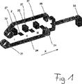
図1は、本発明にしたがう方法を図解する概略図を示す。この方法では、2つの巻き戻し装置またはローラ21および22を介して、エンドレスフィルム24、25をそれぞれ巻き戻し、次にX方向に搬送する。ここに示す実施形態では、順に重ねて配置されるフィルム2、6、7を含む3つの積層27を提供する。本発明にしたがう装置を用いることによって、個々のフィルム2、6、7は、それぞれの積層から取り出され、印刷マークを決定することによって(より具体的には、印刷マークセンサと、照合部分毎にそれぞれの視覚センサを使用することによって)、規定位置に配置される。次に、2つのエンドレスフィルム間で、方向搬送を行う。これに関し、本発明にしたがう別の製造方法では、エンドレスフィルムの使用を省いてもよいことが指摘されよう。
FIG. 1 shows a schematic diagram illustrating a method according to the present invention. In this method,
参照番号29および31は、巻き戻しローラの速度を制御するのに役立つ、2つのバッファ装置を示す。より具体的には、バッファ装置29、31の充填レベルに応じて、巻き戻し装置の速度を制御する。個々の処理ステーションI、II、およびIIIでは、まず初めに、第1のフィルム2を配置し、次に第2のフィルム6をこの第1のフィルム上に配置、次にさらなるフィルム7を第2のフィルム上に同様に配置する。個々の方法ステップにおいて、これらのフィルムを互いに対して位置合わせする。最後に、フィルムまたはフィルムの組、すなわち照合されたフィルムを、それぞれのフィルム始まりとフィルム終わりで、エンドレスフィルム24および25に溶接する。さらなる方法ステップ(詳細に図示せず)では、フィルム2、6、7のサイズに応じて溶接フィルム束を切断する。搬送中、フィルムサイズに応じて、同様にエンドレスフィルム24、25を取り外す。エンドレスフィルムを使用しない場合、それぞれの溶接フィルム束を取り外す。
最後に溶接および切断したフィルム束を、順に積層32に配置する。
The film bundle finally welded and cut is arranged in the
本明細書中に示される束にされたそれぞれ3つのフィルムの代わりに、多数または少数のフィルムを束にすることも可能であり、唯1つのフィルムを、例えばエンドレスフィルム24に接合することも可能である。
Instead of each of the three bundled films shown herein, it is also possible to bundle a large or small number of films, and only one film can be bonded to, for example, the
さらなる工程では、個々のカード部分は、フィルム束から型抜きされることによって製造され、該カード部分は、既にフィルム上に画定されている。 In a further step, individual card parts are produced by being die-cut from a film bundle, which card parts are already defined on the film.
図2〜4は、異なる方法ステップにおける、本発明にしたがう装置を示す。ここでは、それぞれ3つのフィルムを順に重ねて配置するように、3つのワークステーションI、II、およびIIIが提供されている。これらのワークステーションのそれぞれは、第1の移動方向Yにフィルムを移動させるために、第1の移動装置3を備える。ここでは、互いに並行に配置された2つのサーボ軸3a、3b(それぞれのフィルム2、6、7を把持するためのそれぞれの第1の把持装置8が、その上に配置される)の形態で、これらの移動装置が提供されている。ここで、2つの把持装置8の間の最大距離を実現するために、把持装置は、好ましくはそれぞれ、2つのサーボ軸3a、3bの外側に配置される。2つのサーボ軸3a、3bは、互いから独立して制御され得る。それぞれの把持装置は、2つの把持要素8a、8bを備える。
Figures 2 to 4 show an apparatus according to the invention in different method steps. Here, three workstations I, II, and III are provided so that each of the three films is placed one on top of the other. Each of these workstations includes a first moving
参照番号9は、支持部に対してフィルムを固定する固定装置を意味し、特に該フィルムは、すでに位置合わせされている。該支持部は、例えば圧力プランジャ等であり得る。
参照番号11a、11bは、位置マークセンサを示し、該位置マークセンサはそれぞれ、サーボ軸3a、3b上に配置され、好ましくは光スイッチを考慮して設計され、共に第1の位置決定装置を形成する。
Reference numerals 11a and 11b denote position mark sensors, which are respectively arranged on the
これらの印刷マークセンサ11a、11bは、第1の移動方向Yにおけるフィルムの位置を決定するのに役立つ。 These print mark sensors 11a, 11b serve to determine the position of the film in the first movement direction Y.
参照番号5は、フィルムをX方向に移動させることができる第2の移動装置を意味する。ここでは、これらをサーボ軸5a、5bとして設計する。さらに、移動装置5にそれぞれ機械的に連結された、リニアガイド13を提供する。本実施形態では、2つのサーボ軸5a、5bが提供され、これらは同様に互いから独立しており、X方向へのフィルムの移動を可能にする。
把持要素4a、4bを有する対応する第2の把持装置も同様に、X方向へのその移動のために、フィルムを把持するのに役立つ。これらの把持要素4a、4bはまた、可能な限り互いから遠く離れて離間する。
A corresponding second gripping device with
装置から束になったフィルムを取り出すために、装置1を偏向ロール19によって接合する。参照番号12a、12b、12cは、ここでは光学表面センサとして設計される、第2の位置決定装置を示す。そのような第2の位置決定装置を、個々のステーションのそれぞれに提供する。個々のサーボ軸3a、3b上のステーションI、II、IIIのそれぞれにおいて、それぞれの第1の位置決定装置も提供する。
In order to take out the bundled film from the apparatus, the
本発明にしたがう方法を、図2〜4を参照して以下に説明する。第1の方法ステップでは、2つのサーボ軸3a、3b上に配置された2つの把持要素8a、8bによって、個々のフィルムを捕える。この把持されたフィルムをY方向に搬送し、同時に、Y方向への2つのサーボ軸3a、3bの移動によって位置合わせする。さらに、フィルムが通過すると、2つの印刷マークセンサ11a、11bによって、フィルムの2つの印刷マーク位置を調べる。この調査は、Y方向におけるフィルムの正確な位置を決定することができる。
The method according to the present invention is described below with reference to FIGS. In the first method step, the individual films are captured by two gripping elements 8a, 8b arranged on two
さらなる方法ステップでは、フィルムの決定位置に基づいて画定される所定位置で、Y方向への移動を停止する。この時点で、2つの移動装置またはサーボ軸3a、3bを停止する。
In a further method step, the movement in the Y direction is stopped at a predetermined position defined based on the determined position of the film. At this point, the two moving devices or
したがって、フィルム2はY方向において既に位置合わせされ、移動装置3上で把持要素8a、8bによって保持する。さらなる方法ステップでは、フィルム上のさらなる印刷マークの位置を、X方向におけるその位置を決定する目的で読み取る。この印刷マークは、例えば、十字または円であり得て、その正確な位置を、公称位置に対して決定する。この位置を決定するために、表面センサの形での第2の位置決定装置12を使用する。
Thus, the
さらなる方法ステップでは、第2の移動装置5上の把持要素4a、4bが閉じられ、さらなる方法ステップでは、把持装置8または把持要素8a、8bが開かれる。そしてこの時点から、X方向への搬送が可能であり、Y方向への移動を担う第1の把持要素は、もはやフィルムの移動にいかなる影響も与えなくなる。
In a further method step, the
さらなる方法ステップでは、フィルムは、第2の把持要素4a、4bによって一定の路程にわたって第2のステーションIIに移送され、第2の把持装置4によって保持され続ける。しかしながら、X方向における位置の読み取りは、フィルムの移動中も行われ得る。
In a further method step, the film is transferred to the second station II over a certain path by the second
さらなる方法ステップでは、ステーションIIにおいて、第2のフィルム6が、Y方向に第1のフィルム2上に引っ張られ、そこに保持される。この第2のフィルムもまた、上述のように、第2のステーションIIにおいて、位置決定装置11a、11bによってY方向に位置合わせされる。同時に、第1のステーションIにおいて、さらなるフィルムもまたY方向に引っ張られる。さらなる方法ステップでは、第2のフィルム6のX方向における位置に対する印刷マークの位置も同様に、表面センサ12bを用いて読み取られる。同時にこの工程は、第1のステーションIにおいて、さらなるフィルム2上で行われる。ここで既知の2つのフィルム2および6のX位置を考慮して、フィルム2が、フィルム6の下に引っ張られ、固定した状態で保持される。ここでもこれは、フィルムを引っ張ることによって位置合わせが可能となるように、位置合わせ前の位置が必ずX方向における標的位置の正面に位置するような方法で、装置が設定されるということを意味する。
In a further method step, at station II, the second film 6 is pulled over and held on the
より具体的には、この方法のステーションにおいては、2つのフィルム2および6の既知のX位置にしたがって、保持されるフィルム6の下にフィルム2を引っ張ることによって、移動装置5またはXサーボ軸5a、5bの位置合わせ動作を行う。
More specifically, at the station of the method, the moving
さらなる方法ステップでは、ここで位置合わせされた2つのフィルムは、固定装置9によって固定される。さらなる方法ステップでは、2つの移動装置3、5の把持要素が開かれ、2つの移動装置が、それらの開始位置に(すなわち、第1の移動装置の場合は図1において上方に、第2の移動装置の場合は左側に)それぞれ戻される。さらなるステップでは、ここで位置合わせされた2つのフィルムがX方向に搬送され、固定装置は、フィルムの互いへのいかなる移動も防止する。より具体的には、2つのフィルムは、第3のステーションIIIに搬送され、次に固定装置9が開かれる。同時に、さらなる第1のフィルム2が、ステーションIIに移送され、上述のようなさらなるフィルム6が、Y搬送および同時にY位置合わせによって、フィルム2の上に引っ張られ、そこに保持される。ここで、第3のフィルム7が、すでに位置合わせされた2つのフィルム2、6の上に引っ張られるが、ステーションIIIにおいて並行手順が行われる。
In a further method step, the two films aligned here are fixed by a fixing
さらなる方法ステップでは、この場合も、2つのフィルムの既知のX位置にしたがって、保持されたフィルム6の下にフィルム2を移動させることによって、移動装置5の位置合わせ移動を行う。ステーションIIIにおいて、並行手順を行う。すなわちここで、フィルム2および6から成る束を、第3のフィルム7の下に適宜に引っ張る。この時点から、固定装置12aおよび12bによるフィルムの位置合わせされた組の固定から始まる個々の方法ステップが繰り返される。例えば、真空吸引カップおよび送風空気を用いて、個々のフィルムの上述の分離を行い得る。図3は、フィルムのY印刷マークの既知の位置にしたがって既にフィルムがY方向に引っ張られて位置合わせされた状態、または位置合わせされたフィルムが第1の移動装置3の把持要素8a、8bによって保持された状態を示す。図4は、フィルムのすべての組を位置合わせおよび固定した後に、一度X移動装置5の戻り動作を行った状態、および一度フィルムの組を除去ロール19によって離した状態を示す。
In a further method step, again the alignment movement of the moving
ここで、X方向における個々のステーション間の移動が結合されること、すなわち、ステーションIから第2のステーションIIへのフィルム2の移動、およびステーションIIからステーションIIIへのフィルム6の移動が、互いに結合されることがわかる。しかしながら、すでに記載したように、それぞれの新しく追加されたフィルム、例えば、第2のステーションIIのフィルム6、または第3のステーションIIIのフィルム7の移動を介して、位置合わせが行われる。ここで、制御装置が、それぞれの最下部のフィルムもしくはフィルムの組の位置を認識しているという事実を、考慮しなければならない。
Here, the movements between the individual stations in the X direction are combined, ie the movement of the
図5は、本発明にしたがう方法に対する、フィルムの図を示す。このフィルムは、複数のカード要素20を備え、一度個々のフィルムを溶接および接合すると、複合材料から型抜きされる。フィルムの右側および左側縁部にそれぞれ、Y印刷マーク14を提供し、Y印刷マークは、第1の位置決定装置11a、11bによる、Y方向におけるフィルムの位置合わせを可能にする。したがって、Y印刷マーク14は、印刷マークセンサによる検出に役立つ。参照番号15は、X印刷マーク、すなわち、X方向における位置決定に役立つ印刷マークを意味する。ここでは十字に設計されるこのX印刷マークを、光学表面決定センサ12a、12b、および12cによって読み出す。
FIG. 5 shows a film diagram for a method according to the present invention. This film comprises a plurality of
図6は、本発明にしたがう装置のさらなる全体図を示す。記載のように、ここでのこの装置は、3つのフィルムをエンドレスフィルム24上に順に重ねて配置するために、3つのステーションを備える。このエンドレスフィルムも同様に、X方向に移動する。この図でも同様に、個々の移動装置3a、3b、5a、5bを見ることができる。
FIG. 6 shows a further general view of a device according to the invention. As described, the apparatus herein includes three stations for placing three films on top of
出願書類に開示される特性のすべては、それらが単独で、または従来技術との組み合わせて新規である限りにおいて、本発明に不可欠であるとして請求される。 All of the features disclosed in the application documents are claimed as essential to the present invention as long as they are novel, either alone or in combination with the prior art.
1 装置
2、6、7 フィルム
3 移動装置
3a、3b サーボ軸
4 第2の把持装置
4a、4b 把持要素
5 第2の移動装置
5a、5b サーボ軸
8 第1の把持装置
8a、8b 把持要素
9 固定装置
11 第1の位置決定装置
11a、11b 印刷マークセンサ
12 位置決定装置
12a、12b、12c 第2の位置決定装置
13 リニアガイド
14 Y印刷マーク
15 X印刷マーク
19 偏向ロール
20 カード要素
21、22 巻き戻し装置またはローラ
24、25 エンドレスフィルム
27 積層
29、31 バッファ装置
32 積層
DESCRIPTION OF
Claims (11)
少なくとも1つの第1の把持装置(8)によって、第1の個々のフィルム(2)を捕えるステップと、
前記把持装置(8)を前記フィルム(2)と共に、第1の移動方向(Y)に移動させるステップと、
前記第1の移動方向(Y)における前記フィルムの位置を決定し、前記フィルムを前記第1の移動方向(Y)の所定位置に固定するステップと、
第2の移動方向(X)における前記第1のフィルム(2)の位置を決定するステップであって、前記第2の移動方向は、前記第1の移動方向(Y)に略垂直である、ステップと、
前記第1のフィルム(2)を前記第2の移動方向(X)に移動させるステップと
を含み、
前記フィルム(2)は、前記第2の移動方向(X)への搬送のために、第2の把持装置(4)によって把持されることと、
前記第1の把持装置(8)は、前記第1の移動方向(Y)にのみ移動することができ、前記第2の把持装置(4)は、前記第2の移動方向(X)にのみ移動することができることと
を特徴とする、方法。A method for producing a film of a film composite material, comprising:
Capturing the first individual film (2) by at least one first gripping device (8);
Moving the gripping device (8) together with the film (2) in a first movement direction (Y);
Determining a position of the film in the first movement direction (Y), and fixing the film at a predetermined position in the first movement direction (Y);
Determining the position of the first film (2) in a second movement direction (X), the second movement direction being substantially perpendicular to the first movement direction (Y); Steps,
Moving the first film (2) in the second movement direction (X),
The film (2) is gripped by a second gripping device (4) for transport in the second movement direction (X) ;
The first gripping device (8) can move only in the first movement direction (Y), and the second gripping device (4) can move only in the second movement direction (X). A method characterized in that it can be moved .
を特徴とする、請求項1に記載の方法。It said first film (2) is at least partially pulled above or below the second film (6), said film (2,6), based on their respective determined positions, against each other The method of claim 1 , wherein the method is aligned.
を特徴とする、請求項1または2に記載の方法。The second film (6) is pulled at least partially above or below the first film (2), and the films (2, 6) are connected to each other based on their respective determined positions. characterized in that it is aligned against a method according to claim 1 or 2.
を特徴とする、請求項2または3に記載の方法。Wherein the first and the film (2) and said second film (6), characterized in that it is aligned with respect to one another with respect to said second direction of movement (X), according to claim 2 or 3 the method of.
を特徴とする、請求項1〜4のいずれか一項に記載の方法。The method according to any one of claims 1 to 4 , characterized in that once the film (2) has been aligned, the gripping device (8) is removed from the film (2).
を特徴とする、請求項1〜5のいずれか一項に記載の方法。In a further method step, the film (2,6), characterized in that is joined to at least one film carrier (24, 25) The method according to any one of claims 1-5.
第1の移動装置(3)および前記第1の移動装置(3、3a、3b)上に配置された少なくとも1つの把持装置(8)であって、フィルム(2)を把持し、それを第1の方向(Y)に移動させる、第1の移動装置(3)および少なくとも1つの把持装置(8)と、
前記第1の方向(Y)における前記フィルム(2)の位置を決定する第1の位置決定装置(11a、11b)と、
前記第1の位置決定装置(11a、11b)によって決定された位置に応じて、前記第1の移動装置(3、3a、3b)の移動を制御する制御装置と、
第2の移動装置(5、5a、5b)および前記第2の移動装置(5、5a、5b)上に配置された少なくとも1つの第2の把持装置(4)であって、前記フィルムを把持し、それを第2の方向(X)に移動させる、第2の移動装置(5、5a、5b)および少なくとも1つの第2の把持装置(4)と、
前記第2の方向(X)における前記フィルム(2)の位置を決定する第2の位置決定装置(12a、12b、12c)と
を備え、
前記第1の把持装置(8)は、本質的に前記第1の移動方向(Y)にのみ移動することができ、前記第2の把持装置(4)は、本質的に前記第2の移動方向(X)にのみ移動することができること
を特徴とする、装置。An apparatus for manufacturing a film composite material,
A first moving device (3) and at least one gripping device (8) arranged on said first moving device (3, 3a, 3b), gripping film (2) and A first moving device (3) and at least one gripping device (8) for moving in one direction (Y);
A first position determining device (11a, 11b) for determining the position of the film (2) in the first direction (Y);
A control device for controlling the movement of the first moving device (3, 3a, 3b) according to the position determined by the first position determining device (11a, 11b);
A second moving device (5, 5a, 5b) and at least one second gripping device (4) arranged on the second moving device (5, 5a, 5b) for gripping the film A second moving device (5, 5a, 5b) and at least one second gripping device (4) for moving it in the second direction (X);
A second position determining device (12a, 12b, 12c) for determining the position of the film (2) in the second direction (X),
The first gripping device (8) can essentially move only in the first movement direction (Y) and the second gripping device (4) can essentially move in the second movement. Device capable of moving only in direction (X).
前記第1の方向(Y)における前記フィルム(2)の位置を決定する第1の位置決定装置(11a、11b)と、
前記第1の位置決定装置(11a、11b)によって決定された位置に応じて、前記第1の移動装置(3、3a、3b)の移動を制御する制御装置と、
第2の移動装置(5、5a、5b)および前記第2の移動装置(5、5a、5b)上に配置された少なくとも1つの第2の把持装置(4)であって、前記フィルムを把持し、それを第2の方向(X)に移動させる、第2の移動装置(5、5a、5b)および少なくとも1つの第2の把持装置(4)と、
前記第2の方向(X)における前記フィルム(2)の位置を決定する第2の位置決定装置(12a、12b、12c)と
を含む、請求項1〜6のいずれか一項に記載の方法を実行する装置。A first moving device (3, 3a, 3b) and at least one gripping device (8) arranged on the first moving device (3, 3a, 3b), for gripping the film (2); A first moving device (3, 3a, 3b) and at least one gripping device (8) for moving it in a first direction (Y);
A first position determining device (11a, 11b) for determining the position of the film (2) in the first direction (Y);
A control device for controlling the movement of the first moving device (3, 3a, 3b) according to the position determined by the first position determining device (11a, 11b);
A second moving device (5, 5a, 5b) and at least one second gripping device (4) arranged on the second moving device (5, 5a, 5b) for gripping the film A second moving device (5, 5a, 5b) and at least one second gripping device (4) for moving it in the second direction (X);
The second position-determining device for determining the position of the film (2) in a second direction (X) containing (12a, 12b, 12c) and a method according to any one of claims 1 to 6 A device that performs.
を特徴とする、請求項7または8に記載の装置。The device comprises a further first moving device (3), in which a first gripping device (8) is arranged for gripping the film and moving it in the first moving direction (Y) The device according to claim 7 or 8 , characterized in that:
を特徴とする、請求項7〜9のいずれか一項に記載の装置。The device according to any one of claims 7 to 9 , characterized in that the first position determining device (11a, 11b) is an imprint sensor of a printing press.
を特徴とする、請求項7〜10のいずれか一項に記載の装置。The device according to any one of claims 7 to 10 , characterized in that the second position determining device (12a, 12b, 12c) is a surface sensor.
Applications Claiming Priority (3)
| Application Number | Priority Date | Filing Date | Title |
|---|---|---|---|
| DE102006025504A DE102006025504B4 (en) | 2006-05-30 | 2006-05-30 | Method and device for producing film composites |
| DE102006025504.6 | 2006-05-30 | ||
| PCT/EP2007/054856 WO2007137956A1 (en) | 2006-05-30 | 2007-05-21 | Method and device for producing film composites |
Publications (2)
| Publication Number | Publication Date |
|---|---|
| JP2009538749A JP2009538749A (en) | 2009-11-12 |
| JP4875747B2 true JP4875747B2 (en) | 2012-02-15 |
Family
ID=38436744
Family Applications (1)
| Application Number | Title | Priority Date | Filing Date |
|---|---|---|---|
| JP2009512543A Active JP4875747B2 (en) | 2006-05-30 | 2007-05-21 | Method and apparatus for manufacturing a film composite |
Country Status (6)
| Country | Link |
|---|---|
| US (1) | US8206524B2 (en) |
| EP (1) | EP2029360B2 (en) |
| JP (1) | JP4875747B2 (en) |
| CN (1) | CN101454158B (en) |
| DE (1) | DE102006025504B4 (en) |
| WO (1) | WO2007137956A1 (en) |
Families Citing this family (4)
| Publication number | Priority date | Publication date | Assignee | Title |
|---|---|---|---|---|
| DE102008012943B4 (en) | 2008-03-04 | 2018-03-29 | Bundesdruckerei Gmbh | Method and stapler for stapling foils in a foil stack and collating machine for foils |
| DE102009007552A1 (en) * | 2009-02-04 | 2010-08-05 | Bundesdruckerei Gmbh | Process for the production of multi-layer security products |
| DE102012112383A1 (en) * | 2012-12-17 | 2014-06-18 | Bundesdruckerei Gmbh | Method and device for producing a data page for a book-type document |
| DE102013104209A1 (en) * | 2013-04-25 | 2014-10-30 | Wemhöner Surface Technologies GmbH & Co. KG | Method and device for the exact laying of coating material on to be coated in a press carrier plates |
Family Cites Families (18)
| Publication number | Priority date | Publication date | Assignee | Title |
|---|---|---|---|---|
| FR2280516A1 (en) * | 1974-07-31 | 1976-02-27 | Sublistatic Holding Sa | PROCESS AND INSTALLATION FOR MAKING A LARGE WIDTH TRANSFER BAND |
| JPH06294B2 (en) * | 1986-09-03 | 1994-01-05 | 新明和工業株式会社 | Positioning device |
| JPH0710519Y2 (en) * | 1988-08-11 | 1995-03-08 | 富士通株式会社 | Laminating device |
| JPH0397560A (en) * | 1989-09-12 | 1991-04-23 | Hitachi Ltd | Laminating device |
| US5217656A (en) * | 1990-07-12 | 1993-06-08 | The C. A. Lawton Company | Method for making structural reinforcement preforms including energetic basting of reinforcement members |
| JPH0753357B2 (en) * | 1990-12-20 | 1995-06-07 | ソマール株式会社 | Thin film cutting method and its implementation device |
| US5150539A (en) | 1991-02-28 | 1992-09-29 | Sorola Bret S | Swivel construction |
| JPH05330001A (en) * | 1992-05-29 | 1993-12-14 | Canon Inc | Sheet material laminating device |
| US5464690A (en) | 1994-04-04 | 1995-11-07 | Novavision, Inc. | Holographic document and method for forming |
| US5473406A (en) * | 1994-07-21 | 1995-12-05 | Eastman Kodak Company | Apparatus and methods for assembling depth image systems |
| US6409872B1 (en) | 1998-11-06 | 2002-06-25 | Fargo Electronics, Inc. | Identification card printer and laminator |
| FR2791919B1 (en) * | 1999-04-12 | 2001-06-01 | Plastic Omnium Cie | METHOD FOR MAKING A REINFORCED PLASTIC PART BY OVERMOLDING A REINFORCING SHEET, DEVICE FOR IMPLEMENTING THIS PROCESS AND MANUFACTURING LINE COMPRISING THIS DEVICE |
| US6596361B2 (en) * | 2001-03-07 | 2003-07-22 | Ccl Label, Inc. | Lenticular label manufacture |
| JP3931330B2 (en) * | 2001-09-14 | 2007-06-13 | ソニー株式会社 | Hot press plate and card manufacturing equipment |
| CN1240536C (en) * | 2002-03-26 | 2006-02-08 | 厦门新风机实业有限公司 | Composite foam sandwich colour steel-phenolic aldehyde plate and its production technology |
| DE10254504B4 (en) * | 2002-11-22 | 2006-02-16 | Tünkers Maschinenbau Gmbh | Method for laminating two or more identical or different sheets, and device for carrying out the method |
| JP2004358856A (en) * | 2003-06-06 | 2004-12-24 | Hitachi Industries Co Ltd | Method for pasting up film |
| JP2005157012A (en) * | 2003-11-27 | 2005-06-16 | Sharp Corp | Film-sticking method, film-sticking device, and manufacturing method of electronic component using them |
-
2006
- 2006-05-30 DE DE102006025504A patent/DE102006025504B4/en not_active Expired - Fee Related
-
2007
- 2007-05-21 WO PCT/EP2007/054856 patent/WO2007137956A1/en active Application Filing
- 2007-05-21 CN CN2007800200434A patent/CN101454158B/en active Active
- 2007-05-21 EP EP07729300.9A patent/EP2029360B2/en active Active
- 2007-05-21 US US12/302,613 patent/US8206524B2/en active Active
- 2007-05-21 JP JP2009512543A patent/JP4875747B2/en active Active
Also Published As
| Publication number | Publication date |
|---|---|
| US8206524B2 (en) | 2012-06-26 |
| WO2007137956A1 (en) | 2007-12-06 |
| CN101454158A (en) | 2009-06-10 |
| DE102006025504A1 (en) | 2007-12-06 |
| CN101454158B (en) | 2013-09-18 |
| DE102006025504B4 (en) | 2011-05-12 |
| EP2029360B2 (en) | 2023-11-01 |
| JP2009538749A (en) | 2009-11-12 |
| US20100018627A1 (en) | 2010-01-28 |
| EP2029360A1 (en) | 2009-03-04 |
| EP2029360B1 (en) | 2012-04-04 |
Similar Documents
| Publication | Publication Date | Title |
|---|---|---|
| JP2015222370A (en) | Exposure apparatus | |
| JP6128923B2 (en) | Sheet processing equipment | |
| JP4875747B2 (en) | Method and apparatus for manufacturing a film composite | |
| JP2012218445A (en) | Apparatus for producing book, particularly photobook and/or image book | |
| JP2002193545A (en) | Method and device of manufacturing newspaper | |
| JP2007161354A (en) | Unpacking system and unpacking method | |
| JP5961105B2 (en) | Laminating apparatus and laminated body forming method | |
| CN112310458A (en) | Lamination machine | |
| EP2860116A1 (en) | Packaging machine, packaging system, and packaging method | |
| JP2007084298A (en) | Sheet transfer and stacking device and automatic sheet bundle packaging system | |
| JPH08162364A (en) | Method and apparatus for stacking sheets of multilayer electronic part | |
| JP2914535B2 (en) | Sheet laminating equipment | |
| KR101053343B1 (en) | Laminator for Flat Panel Display Glass and Laminating Method Using the Same | |
| JP2008050053A (en) | Paper sheet processor and its seal applying method | |
| KR100772151B1 (en) | Apparatus and method for processing sheet laminates | |
| JP3412920B2 (en) | Laminator | |
| JPH09155797A (en) | Blanking device for manufacture of card | |
| JP4193809B2 (en) | Thin plate laminator | |
| JP3675267B2 (en) | Method and apparatus for producing laminated block for producing laminated body | |
| EP3782821B1 (en) | Paper stack press machine | |
| JP2005123270A (en) | Manufacturing equipment of laminated ceramic component and its manufacturing method | |
| JP2009018031A (en) | Method of laminating textiles and textile lamination device | |
| JP5645225B2 (en) | Lamination molding system and lamination molding method | |
| KR100653776B1 (en) | a taping machine for lead frame | |
| JP3298238B2 (en) | Thin plate aligner |
Legal Events
| Date | Code | Title | Description |
|---|---|---|---|
| A977 | Report on retrieval |
Free format text: JAPANESE INTERMEDIATE CODE: A971007 Effective date: 20110630 |
|
| A131 | Notification of reasons for refusal |
Free format text: JAPANESE INTERMEDIATE CODE: A131 Effective date: 20110707 |
|
| A521 | Request for written amendment filed |
Free format text: JAPANESE INTERMEDIATE CODE: A523 Effective date: 20111006 |
|
| TRDD | Decision of grant or rejection written | ||
| A01 | Written decision to grant a patent or to grant a registration (utility model) |
Free format text: JAPANESE INTERMEDIATE CODE: A01 Effective date: 20111115 |
|
| A01 | Written decision to grant a patent or to grant a registration (utility model) |
Free format text: JAPANESE INTERMEDIATE CODE: A01 |
|
| A61 | First payment of annual fees (during grant procedure) |
Free format text: JAPANESE INTERMEDIATE CODE: A61 Effective date: 20111125 |
|
| FPAY | Renewal fee payment (event date is renewal date of database) |
Free format text: PAYMENT UNTIL: 20141202 Year of fee payment: 3 |
|
| R150 | Certificate of patent or registration of utility model |
Ref document number: 4875747 Country of ref document: JP Free format text: JAPANESE INTERMEDIATE CODE: R150 Free format text: JAPANESE INTERMEDIATE CODE: R150 |
|
| R250 | Receipt of annual fees |
Free format text: JAPANESE INTERMEDIATE CODE: R250 |
|
| S533 | Written request for registration of change of name |
Free format text: JAPANESE INTERMEDIATE CODE: R313533 |
|
| R350 | Written notification of registration of transfer |
Free format text: JAPANESE INTERMEDIATE CODE: R350 |
|
| R250 | Receipt of annual fees |
Free format text: JAPANESE INTERMEDIATE CODE: R250 |
|
| R250 | Receipt of annual fees |
Free format text: JAPANESE INTERMEDIATE CODE: R250 |
|
| R250 | Receipt of annual fees |
Free format text: JAPANESE INTERMEDIATE CODE: R250 |
|
| R250 | Receipt of annual fees |
Free format text: JAPANESE INTERMEDIATE CODE: R250 |
|
| R250 | Receipt of annual fees |
Free format text: JAPANESE INTERMEDIATE CODE: R250 |
|
| R250 | Receipt of annual fees |
Free format text: JAPANESE INTERMEDIATE CODE: R250 |
|
| R250 | Receipt of annual fees |
Free format text: JAPANESE INTERMEDIATE CODE: R250 |
|
| R250 | Receipt of annual fees |
Free format text: JAPANESE INTERMEDIATE CODE: R250 |