JP4871192B2 - Active vibration isolator and vibration control unit used therefor - Google Patents
Active vibration isolator and vibration control unit used therefor Download PDFInfo
- Publication number
- JP4871192B2 JP4871192B2 JP2007104616A JP2007104616A JP4871192B2 JP 4871192 B2 JP4871192 B2 JP 4871192B2 JP 2007104616 A JP2007104616 A JP 2007104616A JP 2007104616 A JP2007104616 A JP 2007104616A JP 4871192 B2 JP4871192 B2 JP 4871192B2
- Authority
- JP
- Japan
- Prior art keywords
- vibration
- movable mass
- gain
- control
- sensor
- Prior art date
- Legal status (The legal status is an assumption and is not a legal conclusion. Google has not performed a legal analysis and makes no representation as to the accuracy of the status listed.)
- Active
Links
Images


Description
本発明は、例えば電子顕微鏡のような精密機器に対する振動の影響を軽減するための除振装置等に関し、特に、それらの機器に振動を減殺するような制御力を付加するようにしたアクティブタイプのものに係る。 The present invention relates to a vibration isolator for reducing the influence of vibration on a precision instrument such as an electron microscope, and more particularly to an active type that adds a control force that reduces vibration to the instrument. Related to things.
従来より、この種のアクティブ除振装置としては、例えば特許文献1に開示されるように、除振対象物(荷)を基礎に対して空気ばねにより支持するとともに、その除振対象物の振動状態をセンサにより検出し、この検出信号をフィードバックしてコントローラによりアクチュエータを駆動することで、当該除振対象物にその振動を減殺するような振動的な制御力を付加するようにしたものが知られている。
Conventionally, as an active vibration isolator of this type, as disclosed in, for example,
このものではアクチュエータとして空気ばね自体を利用するようにしており、その空気ばねに対する空気の給排系にサーボ弁を配設し、これをコントローラにより制御して空気ばねの内圧を変化させることにより、除振対象物に制御力を付加するようにしている。 In this device, an air spring itself is used as an actuator, and a servo valve is arranged in an air supply / discharge system for the air spring, and this is controlled by a controller to change the internal pressure of the air spring. A control force is applied to the vibration isolation object.
そうして空気ばねをアクチュエータとして利用した場合は、大きな出力を比較的容易に得られるという利点がある一方で、空気ばねの内圧の制御には応答性という面で難があり、高い応答性を得ようとすれば特別に高速の制御弁等、高価な部品が必要になって、コストアップを招くという問題がある。 Thus, when an air spring is used as an actuator, there is an advantage that a large output can be obtained relatively easily. On the other hand, control of the internal pressure of the air spring is difficult in terms of responsiveness, and high responsiveness is achieved. If it is going to obtain, expensive parts, such as a high-speed control valve, will be needed, and there exists a problem that a cost increase will be caused.
この点につき特許文献2に記載の防振台では、脚部に設けた空気ばねと架台との間に、電磁石を備えた制振機構を介挿して、これにより制御力を発生させるようにしている。この制振機構は、中空状の支持体の内部にドーナツ状の板ばねを介して可動質量を弾性支持し、その上方に配設した電磁石によって該可動質量を動かすときの反力によって、入力振動を相殺するようにしている。
With respect to this point, in the vibration isolator described in
ところで、前記のような制振機構において可動質量の重量を全て板ばねで支えようとすると、その剛性(ばね定数)をかなり高くせざるを得ず、この板ばねと可動質量とによって構成される付加振動系の固有振動数が高くなり、除振性能に悪い影響を及ぼす虞れがある。そこで、前記文献に記載のものでは、可動質量の上方に位置する電磁石により吸引力を発生させて、可動質量の重量の一部を支えるようにしている。
ところが、前記文献に記載の制振機構では、可動質量をドーナツ状の板ばね1枚のみによって支持体に連結しているため、その可動質量が上下方向に移動するのみならず、前後左右に揺動して、水平方向に余計な振動を生じる虞れがある。このことは、精密機器を搭載する除振装置においては甚だ好ましくない。 However, in the vibration damping mechanism described in the above document, since the movable mass is connected to the support body by only one donut-shaped leaf spring, the movable mass not only moves in the vertical direction, but also swings back and forth and right and left. There is a risk of causing extra vibration in the horizontal direction. This is extremely undesirable in a vibration isolator equipped with precision equipment.
また、アクチュエータにより可動質量を駆動する際に、前記のように可動質量が揺動することに起因して、上下方向の駆動反力が変動することがあり、こうなると除振対象物に狙い通り適切な制御力を付加することができない。 Further, when the movable mass is driven by the actuator, the driving reaction force in the vertical direction may fluctuate due to the swing of the movable mass as described above. Appropriate control force cannot be added.
斯かる点に鑑みて本発明の主な目的は、前記のような制振機構における可動質量の支持構造に工夫を凝らし、その揺動を抑えて余計な振動を生じないようにするとともに、駆動反力の大きさを正確に制御できるようにして、除振性能を向上させることにある。 In view of such a point, the main object of the present invention is to devise a support structure for the movable mass in the vibration damping mechanism as described above so as to prevent the vibration from being generated by suppressing the oscillation and driving. It is to improve the vibration isolation performance by accurately controlling the magnitude of the reaction force.
前記の目的を達成するために、本発明では、可動質量の移動方向両側にそれぞれ延びるように軸部を設け、その両端部を各々軸心方向には容易に移動する一方、軸心に直交する方向には殆ど移動しないようにして除振或いは制振対象物に連結したものである。 In order to achieve the above object, in the present invention, a shaft portion is provided so as to extend on both sides of the moving direction of the movable mass, and both end portions thereof are easily moved in the axial direction, while being orthogonal to the axial center. It is connected to the object of vibration isolation or vibration suppression so that it hardly moves in the direction.
具体的に請求項1の発明は、基礎に対して弾性支持した除振対象物に制振機構を取り付けて、所定方向の振動を減殺するような制御力を付加するようにしたアクティブ除振装置を対象として、前記制振機構には、可動質量と、前記除振対象物に取り付けられて前記可動質量を前記所定方向に駆動し、その反力を当該除振対象物に作用させるアクチュエータと、を備える。
Specifically, the invention according to
そして、前記可動質量における前記所定方向の両側からそれぞれ延びる軸部を設けて、この軸部の両端部を各々、軸心方向の移動を許容し且つ軸心に直交する方向の移動を規制するような連結部材によって、前記除振対象物に連結するとともに、前記連結部材を、内周縁部が前記軸部の外周面に連結された環状の板バネにより構成するようにした。 Then, shaft portions extending from both sides of the movable mass in the predetermined direction are provided, and both end portions of the shaft portions are allowed to move in the axial direction and restrict movement in a direction perpendicular to the axial center. by Do coupling member, as well as coupled to the object to be vibration-isolated, the coupling member, the inner peripheral edge portion and so that formed structure by concatenated annular plate spring on an outer circumferential surface of the shaft portion.
前記の構成により、制振機構から除振対象物に制御力を付加し、その所定方向の振動を減殺するときには、例えばセンサにより除振対象物の所定方向の振動状態を検出し、このセンサからの信号に応じてアクチュエータを作動させて、可動質量を前記所定方向に駆動することで、その駆動反力(制御力)を除振対象物に作用させることができる。 With the above configuration, when a control force is applied from the vibration damping mechanism to the vibration isolation target and the vibration in the predetermined direction is attenuated, for example, the vibration state of the vibration isolation target in the predetermined direction is detected by a sensor, By actuating the actuator in accordance with this signal and driving the movable mass in the predetermined direction, the driving reaction force (control force) can be applied to the vibration isolation object.
そうして所定方向に駆動される可動質量が、その方向に延びる軸部の両端部において、即ち駆動される方向に或る程度以上、離れた2箇所において各々除振対象物に連結されており、しかも、各連結箇所において軸心に直交する方向への移動が規制されているので、可動質量は殆ど揺動せず、軸心の方向にのみ駆動されるようになる。よって、その駆動の反力として狙い通りの制御力を除振対象物に付加することができるとともに、可動質量の揺動による余計な振動の発生を抑制できる。 Thus, the movable mass driven in a predetermined direction is connected to the vibration isolating object at both ends of the shaft portion extending in the direction, that is, at a certain distance or more in the driven direction. In addition, since the movement in the direction perpendicular to the axis is restricted at each connection point, the movable mass hardly oscillates and is driven only in the direction of the axis. Therefore, the desired control force can be applied to the vibration isolation target as the driving reaction force, and the occurrence of extra vibration due to the swing of the movable mass can be suppressed.
前記のような連結部材としては例えば板ばねを利用することができ、特に金属製のものを用いれば樹脂等に比べて内部損失が小さいため、可動質量の駆動制御における応答性を高くする上で有利である。しかも金属製の板ばねは低コストで製造でき、特性のばらつきも比較的少ない。 For example, a plate spring can be used as the connecting member as described above. Particularly, when a metal member is used, the internal loss is smaller than that of resin or the like. It is advantageous. Moreover, metal leaf springs can be manufactured at low cost and have relatively little variation in characteristics.
但し、そうして可動質量の軸部を板ばねを介して連結するようにした場合、その可動質量の移動方向が例えば上下方向であって、その重量を板ばねによって支えなくてはならないとすれば、その剛性(ばね定数)をかなり高くせざるを得ず、この板ばねと可動質量とによって構成される振動系(除振対象物に対する付加振動系)の固有振動数が相対的に高くなってしまう。このことは除振性能に悪い影響を及ぼす虞れがある。 However, if the shaft portion of the movable mass is connected via a leaf spring, the moving direction of the movable mass is, for example, the vertical direction, and its weight must be supported by the leaf spring. For example, the rigidity (spring constant) has to be considerably increased, and the natural frequency of the vibration system (additional vibration system for the vibration isolation object) constituted by the leaf spring and the movable mass becomes relatively high. End up. This may adversely affect the vibration isolation performance.
そこで、好ましいのは、板ばね等の連結部材とは別に、可動質量の重量を支えるためのコイルばねを備えることである(請求項2)。コイルばねは、一般的にばね定数を小さくしても、その分、自由長を長くすれば十分なばね力が得られるので、これにより可動質量の重量を支えるようにすれば、固有振動数は低く設定することができる。 Therefore, it is preferable that a coil spring for supporting the weight of the movable mass is provided separately from the connecting member such as a leaf spring (Claim 2 ). In general, even if the spring constant is reduced, a sufficient spring force can be obtained by increasing the free length accordingly. Therefore, if the weight of the movable mass is supported by this, the natural frequency is Can be set low.
尚、上述した従来例(特許文献2)には、電磁石の吸引力で可動質量の重量を支えることが記載されているが、こうすると徒に電力消費が嵩み、発熱による問題を生じる虞れもある上に、装置の停止時等には電磁石が吸引力を発生せず、可動質量の重量が全て板ばねに負荷されることになるので、その耐久性を考慮すれば、板ばねをあまり柔らかなものとすることはできない。 Although the above-described conventional example (Patent Document 2) describes that the weight of the movable mass is supported by the attractive force of the electromagnet, this increases the power consumption and may cause problems due to heat generation. In addition, when the device is stopped, the electromagnet does not generate an attractive force, and all the weight of the movable mass is loaded on the leaf spring. It cannot be soft.
前記のようにコイルばねによって可動質量の重量を支えるようにする場合、そのコイルばねは、軸心が可動質量の移動方向に沿うように配置されることになるが、その場合に好ましいのは、コイルばねを可動質量の軸部を周回するように配置することである(請求項3)。こうすれば、可動質量の揺動を抑えるために、板ばね等による軸部の連結箇所同士を或る程度以上、大きく離したときでも、その間にコイルばねが収まることになり、スペースの有効活用によって制振機構の大型化を抑制できる。 When the weight of the movable mass is supported by the coil spring as described above, the coil spring is disposed so that the axis is along the moving direction of the movable mass. The coil spring is arranged so as to go around the shaft portion of the movable mass (claim 3 ). In this way, in order to suppress the swing of the movable mass, even if the connecting portions of the shaft portions by leaf springs or the like are largely separated from each other to some extent, the coil springs are accommodated between them, and the space is effectively used. Therefore, the increase in size of the vibration control mechanism can be suppressed.
ところで、そうして可動質量を駆動する反力によって除振対象物の振動を減殺するような制御力を得るためには、その除振対象物に少なくとも所定方向の振動状態を検出するように加速度センサ、変位センサ等の振動センサを配設し、この振動センサからの信号を受けてコントローラによりアクチュエータの作動を制御して、可動質量を所定方向に駆動するようにすればよい(請求項4)。 By the way, in order to obtain a control force that attenuates the vibration of the vibration isolation object by the reaction force that drives the movable mass, acceleration is performed so that the vibration isolation object detects at least a vibration state in a predetermined direction. sensor, disposed vibration sensor such as a displacement sensor, and controls the operation of the actuator by the controller in response to a signal from the vibration sensor, it is sufficient to drive the movable mass in a predetermined direction (claim 4) .
その場合に、制振機構における可動質量の移動方向の位置を検出するための位置センサも設け、この位置センサからの信号を受けるコントローラにより、可動質量の位置を加味して、アクチュエータの作動を制御するようにしてもよい(請求項5)。例えば可動質量を中立位置からの変位量に応じて駆動するようにすれば、それにより付加振動系の見かけのばね定数を調整して、固有振動数を低下させることができる。また、可動質量の速度に応じて駆動力を調整するようにすれば、減衰の大きさを調整することができる。 In that case, a position sensor is also provided to detect the position of the movable mass in the moving direction in the vibration damping mechanism, and the controller that receives the signal from this position sensor controls the operation of the actuator with the position of the movable mass. (Claim 5 ). For example, if the movable mass is driven in accordance with the amount of displacement from the neutral position, the apparent spring constant of the additional vibration system can be adjusted thereby to reduce the natural frequency. Further, if the driving force is adjusted according to the speed of the movable mass, the magnitude of the attenuation can be adjusted.
さらに、除振装置の設置されている基礎側にも振動センサを配置し、この振動センサからの信号をコントローラに入力して、これによりアクチュエータの作動を制御するようにしてもよい。こうすれば、除振対象物に基礎側から伝達される振動を減殺するような制御力を付加する、いわゆるフィードフォワード除振制御を実現できる。 Further, a vibration sensor may be arranged on the base side where the vibration isolator is installed, and a signal from the vibration sensor may be input to the controller, thereby controlling the operation of the actuator. By doing so, it is possible to realize so-called feedforward vibration isolation control that adds a control force that attenuates vibration transmitted from the foundation side to the vibration isolation object.
前記のような制振機構は、それを一体的に除振装置に組み込むこともできるが、除振装置とは別体の制振ユニットとして設け、それを対象物に共振が生じる箇所乃至その近傍に取り付けるようにしてもよい。 Although the vibration damping mechanism as described above can be integrated into the vibration isolator, it is provided as a vibration damping unit separate from the vibration isolator, and it is located at or near the place where resonance occurs in the object. You may make it attach to.
すなわち、請求項6の発明は、制振対象物に取り付けて所定方向の振動を減殺するような制御力を付加するための制振ユニットであって、前記制振対象物に取り付けられるケースと、可動質量と、前記ケースに固定され、前記可動質量を前記所定方向に駆動して、その反力をケースを介して前記制振対象物に作用させるアクチュエータと、を備えるものである。
That is, the invention of
そして、前記可動質量には前記所定方向の両側にそれぞれ延びる軸部が設けられ、この軸部の両端部が各々、軸心方向の移動を許容し且つ軸心に直交する方向の移動を規制するような連結部材によって、前記ケースに連結され、前記連結部材は、内周縁部が前記軸部の外周面に連結された環状の板バネからなるものとする。 The movable mass is provided with shaft portions extending on both sides in the predetermined direction, and both end portions of the shaft portion permit movement in the axial direction and restrict movement in a direction perpendicular to the axial center. the connecting member as being connected to the case, the connecting member, the inner peripheral edge and shall such a leaf spring of the annular coupled to the outer peripheral surface of the shaft portion.
前記構成の制振ユニットを、例えば空気バネ式の除振台のような所謂パッシブタイプの除振装置の除振対象物(制振対象物)に取り付ければ、簡易的にアクティブタイプの除振装置を構成することができ、上述した請求項1の発明の作用が容易に得られる。また、精密機器の局所的な振動がその機器の性能に影響を与える場合に、その振動の影響を受けやすい部位や特に振幅の大きい部位に前記の制振ユニットを取り付ければ、簡単に機器の性能を向上させることができる。 If the vibration damping unit having the above configuration is attached to a vibration isolation object (vibration suppression object) of a so-called passive type vibration isolation device such as an air spring type vibration isolation table, for example, an active type vibration isolation device can be simply used. Thus, the operation of the first aspect of the present invention can be easily obtained. In addition, when local vibrations of precision equipment affect the performance of the equipment, the performance of the equipment can be easily achieved by attaching the vibration control unit to a part that is susceptible to the vibration or a part with a particularly large amplitude. Can be improved.
前記制振ユニットにおいて可動質量の重量を支えるように、ケースにコイルばねを配設すれば、前記した請求項3の発明と同じ作用が得られるし、そのケースに振動センサを配設しておいて、これにより対象物の振動状態を検出するようにすれば、別途、振動センサを配設する必要もないので、より好ましい(請求項7)。
If a coil spring is provided in the case so as to support the weight of the movable mass in the vibration suppression unit, the same effect as that of the invention of
以上、説明したように、本発明に係るアクティブ除振装置によると、除振対象物の所定方向の振動を減殺するような制御力が可動質量の駆動反力として得られるように構成されたものにおいて、その可動質量を環状の板バネにより駆動方向のみに移動するように支持することによって、狙い通りの制御力が得られるとともに、可動質量の揺動による余計な振動が実質、生じなくなって、精密除振台にも適用し得る高い除振性能を実現できる。 As described above, the active vibration isolator according to the present invention is configured such that a control force capable of reducing the vibration in a predetermined direction of the vibration isolation object is obtained as the driving reaction force of the movable mass. In this case, by supporting the movable mass so as to move only in the driving direction by an annular leaf spring , an intended control force can be obtained, and unnecessary vibration due to the oscillation of the movable mass is substantially eliminated. High vibration isolation performance that can be applied to precision vibration isolation tables can be realized.
また、上下方向の振動を減殺する場合を考慮して、可動質量の重量を支えるコイルばねを設ければ、除振対象物に対し付加振動系となる制振機構の固有振動数を低く設定することができ、除振性能を高める上で有利になる。 In addition, considering the case of reducing the vibration in the vertical direction, if a coil spring that supports the weight of the movable mass is provided, the natural frequency of the vibration damping mechanism that is an additional vibration system is set low for the vibration isolation object. This is advantageous in improving the vibration isolation performance.
さらに、前記の制振機構を除振対象物とは別体の制振ユニットとして構成すれば、このユニットを取り付けるだけで、所謂パッシブタイプの除振装置に簡易的にアクティブ除振機能を付加することができる。特に、対象物に共振が生じる箇所乃至その近傍に制振ユニットを取り付ければ、効果が高い。 Furthermore, if the vibration damping mechanism is configured as a vibration damping unit separate from the object to be vibration-damped, an active vibration damping function can be easily added to a so-called passive type vibration damping device simply by attaching this unit. be able to. In particular, if a vibration control unit is attached at a location where resonance occurs in the object or in the vicinity thereof, the effect is high.
以下、本発明の実施形態を図面に基づいて詳細に説明する。尚、以下の好ましい実施形態の説明は、本質的に例示に過ぎず、本発明、その適用物或いはその用途を制限することを意図するものではない。 Hereinafter, embodiments of the present invention will be described in detail with reference to the drawings. It should be noted that the following description of the preferred embodiment is merely illustrative in nature, and is not intended to limit the present invention, its application, or its use.
図1には、本発明に係るアクティブ除振装置の一実施形態である精密除振台Aの構成を模式的に示す。この除振台Aは、例えば半導体関連の製造装置、試験機器や電子顕微鏡、レーザ顕微鏡等の精密計測機器のように、振動の影響を受けやすい精密な機器Dを搭載して、それらを床の振動からできるだけ絶縁した状態で設置するためのものである。 FIG. 1 schematically shows a configuration of a precision vibration isolation table A that is an embodiment of an active vibration isolation device according to the present invention. This vibration isolation table A is equipped with precision equipment D that is easily affected by vibrations, such as semiconductor-related manufacturing equipment, test equipment, electron microscopes, laser microscopes, and other precision measuring equipment. It is intended to be installed in a state insulated from vibration as much as possible.
図示の除振台Aは、前記のような機器Dの搭載される定盤1を通常は3個(4個以上でもよい)の空気ばね2,2,…(図には2つのみ示す)によって弾性的に支持するものであり、その定盤1及び搭載機器Dが除振対象物となる。また、図示の除振台A自体は所謂パッシブタイプのもので、図示は省略するが、各空気ばね2には高圧空気を供給又は排気するための空気圧回路が接続されて、レベリングバルブ等の作動により定盤1の高さを概略一定に維持するようになっている。
The illustrated anti-vibration table A usually has three (or four or more) air springs 2, 2,... (Only two are shown in the figure) on which the
この実施形態では、機器Dの上部に制振ユニットUを取り付けて、これにより付加する制御力によって機器Dの上下方向の振動を減殺するようにしており、この制御ユニットUを含めた精密除振台A全体としては簡易的なアクティブタイプの除振装置を構成する。制振ユニットUは一般にアクティブマスダンパーと呼ばれるもので、機器Dに固定したケース3内の可動質量4をリニアモータ5により駆動し、その反力をケース3を介して機器Dに付加するものである。尚、図には制振ユニットUを実際よりも大きく示している。
In this embodiment, the vibration damping unit U is attached to the upper part of the device D, and the vertical vibration of the device D is attenuated by the control force applied thereby. The entire table A constitutes a simple active type vibration isolator. The damping unit U is generally called an active mass damper, and drives the movable mass 4 in the
(制振ユニット)
前記制振ユニットUについて詳しくは、まず、そのケース3が全体として図の上下方向に長い円筒状とされ、その下端に例えば矩形状の基板30が配設されて、4隅を機器Dの上部に締結されている。一方、ケース3の上端は円板状の上蓋31によって閉塞されており、それらの中間で周壁部分を構成するケース3の本体は、その概略下半部を構成する下半部材32と、残りの上半部のうちの上部を構成する上端部材33と、それらの中間の中間部材34とに3分割されている。
(Vibration control unit)
Specifically, first, the
また、ケース3の内部は、図では下側から順に第1〜第3の3つの区画壁35〜37によって中心軸線Zの方向に4つの空間s1〜s4に区分けされている。第1区画壁35は、下半部材32における上下の略中央部に位置し、その下方の基板30との間に第1区分空間s1を区画する。第2、第3の区画壁36,37は、下半部材32及び中間部材34の境界部を挟んでその下方及び上方に離れており、第2区画壁36が下方の第1区画壁35との間に第2区分空間s2を、また、上方の第3区画壁37との間には第3区分空間s3を、それぞれ区画している。さらに、第3区画壁37は上方の上蓋31との間に第4区分空間s4を区画している。
Further, the inside of the
前記第1区分空間s1には加速度センサ6が収容されており、図の例では基板30に固定されて機器Dの上下方向の振動による加速度を検出するようになっている。また、第2区分空間s2にはリニアモータ5が収容されている。このリニアモータ5のケースは第2区隔壁36の下部に固設されており、該第2区隔壁36に形成された貫通穴に下方から挿通されたロッドが、ケース3の中心軸線Zに沿って第2区画壁36よりも上方の第3区分空間s3に突出している。
An
そうしてリニアモータ5のロッドが突出する第3区分空間s3には、金属製の板ばね7が配設されている。この板ばね7は、一例を図2に示すように円盤状をなし、中心部及び外周部の所定範囲を除いた径方向の中間部位に複数の貫通溝7a,7a,…が形成されている。この貫通溝7a,7a,…は、同じ円周上に互いに対向して配置された概略半円周状の2つの貫通溝7a,7aが対をなし、それらが内周側から外周側に向かって周方向に1/4周ずつずれながら、図の例では5対、並設されている。
Thus, a
また、前記板ばね7の外周部には、ケース3の下半部材32と中間部材34とを連結するボルト等(図示せず)の挿入孔7b,7b,…が周方向に略等間隔を空けて形成されており、この外周部が前記下半部材32の上端面と中間部材34の下端面との間に挟持されて、ケース3に連結される。一方、板ばね7の中心部には円形断面の中心孔7cが形成されており、以下に述べる可動質量4の軸部材41の下端部が嵌挿されるとともに、この軸端がリニアモータ5のロッドの上端に連結されて、これらの両端間に板ばね7の中心孔7cの周縁部が挟持されるようになっている。
Further,
前記第3区画壁37よりも上方の第4区分空間には、略円筒状の本体部40とそれを貫通する軸部材41とを有する可動質量4が収容されている。この可動質量4の本体部40の下面から軸部材41が下方に長く延びて、第3区隔壁37の貫通穴に上方から挿通され、その下方の第3区分空間s3に突出している。この軸部材41の下端部は、前記したように板ばね7の中心孔7cに嵌挿されるとともに、リニアモータ5のロッドの上端と連結されている。換言すれば、可動質量4の軸部材41の下端部は板ばね7によって、ケース3に連結されている。
In the fourth section space above the
一方、前記軸部材41は、可動質量4の本体部40の上面から上方にも延びていて、その上端部が前記と同一の板ばね7によってケース3に連結されている。すなわち、軸部材41の上端部が板ばね7の中心孔7cに嵌挿されて連結される一方、板ばね7の外周部は、ケース3の上端部材33の下端面と中間部材34の上端面との間に挟持されている。
On the other hand, the
こうして可動質量4は、ケース3の中心軸線Zの方向に延びる軸部材41の両端部が各々、その軸線Z(軸部材41の軸心と合致)方向の移動を許容し且つ軸線Zに直交する方向の移動を規制する板ばね7,7(連結部材)によって、ケース3に連結されており、その移動方向である軸線Z方向に離れた2箇所において、それぞれ軸線Zに直交する方向への移動が規制されている。よって、可動質量4は、軸線Zの方向(図の上下方向)には比較的容易に移動するが、前後左右に揺動することは殆どない。
In this way, the movable mass 4 allows both ends of the
そうして上下方向にのみ移動可能な可動質量4の重量を支えるように、前記第4区分空間s4にはコイルばね8が配設されている。すなわち、可動質量4の軸部材41は、上方に比べて下方に長く延びていて、それを周回するようにコイルばね8が可動質量本体部40の下方にて軸部材41の軸心と略同軸に配置されている。コイルばね8の上端は可動質量本体部40の下部に固定される一方、下端は、第3区隔壁37上に配設された台座38に嵌め込まれている。コイルばね8が撓んで可動質量4の重量を支える中立位置では、板ばね7,7はいずれも略平坦な、即ち、上方にも下方にも殆ど撓んでいない状態に保たれている。
A coil spring 8 is disposed in the fourth section space s4 so as to support the weight of the movable mass 4 that can move only in the vertical direction. That is, the
そのようにコイルばね8によって可動質量4の重量を支えるのは、除振対象である機器Dに対し付加振動系となる制振ユニットUの固有振動数が高くならないようにするためである。すなわち、図示の如く可動質量4が上下方向に移動するように制振ユニットUを配置した場合、リニアモータ5の駆動力が作用しない状態では可動質量4の重量がそのまま板ばね7,7に加わることになり、この重量を全て板ばね7,7,によって支えようとすれば、その剛性(ばね定数)を高くせざるを得ない。
The reason why the weight of the movable mass 4 is supported by the coil spring 8 is to prevent the natural frequency of the vibration damping unit U serving as an additional vibration system from being increased with respect to the device D that is the object of vibration isolation. That is, when the damping unit U is arranged so that the movable mass 4 moves in the vertical direction as shown in the figure, the weight of the movable mass 4 is directly applied to the
そうすると、可動質量4と板ばね7,7とによって構成される振動系(機器Dに対する付加振動系)の固有振動数が高くなってしまい、機器D及び定盤1と空気ばね2,2,…とによって構成される除振台Aの主振動系の固有振動数に近づくことから、制振ユニットUの作動、即ちリニアモータ5による可動質量4の駆動によって機器Dの振動を効果的に抑えることが難しくなる。
Then, the natural frequency of the vibration system (additional vibration system to the device D) constituted by the movable mass 4 and the
また、そうして板ばね7,7の剛性が高くなると、それを変形させるのにリニアモータ5の推力が消費されてしまい、可動質量4の駆動によって得られる反力が安定しなくなる虞れもある。
Further, if the rigidity of the
この点、コイルばねは、そのばね定数が低くても、自由長を長くして撓み量を大きくすれば、大きな荷重を支えることができるので、前記のように可動質量4の重量を支えるコイルばね8を配設すれば、そのコイルばね8と板ばね7,7とを合わせた付加振動系のばね定数はあまり高くしなくても済み、固有振動数は低く設定することができるのである。
In this respect, even if the spring constant of the coil spring is low, a large load can be supported if the free length is increased and the amount of deflection is increased, so that the coil spring that supports the weight of the movable mass 4 as described above. If 8 is provided, the spring constant of the additional vibration system combining the coil spring 8 and the
−制振ユニットの制御−
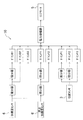
前記の如く構成された制振ユニットUの作動、即ちリニアモータ5による可動質量4の駆動制御は、制振ユニットUとは別体のコントローラ10によって行われる。すなわち、図3に一例を示すように、コントローラ10は、加速度センサ6からの信号(上下方向の加速度z″)を入力し、これを2回積分して得られる変位zに対しゲインB1を乗算するとともに、加速度z″を1回積分した速度z′にゲインB2を乗算し、また、加速度z″に制御ゲインB3を乗算した上で、それらを合算して求めた制御信号を増幅して、リニアモータ5へ出力する。
-Control of vibration control unit-
The operation of the damping unit U configured as described above, that is, the drive control of the movable mass 4 by the
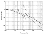
前記の制御においては速度z′のフィードバックが基本であり、これは制振ユニットUによって主振動系に減衰を付加するという意味を持つ。制振ユニットUを付加することによって除振台Aは2自由度の振動系になるが、速度z′のフィードバック制御によって減衰が加わり、共振倍率が低下するので、図4に実線のグラフaで示すように主振動系の共振を抑えることができる。但し可動質量4の共振は残る。尚、図に仮想線のグラフbで示すのは、制振ユニットUを付加しない所謂パッシブの状態である。 In the above control, feedback of the speed z ′ is fundamental, which means that the damping unit U adds damping to the main vibration system. By adding the vibration damping unit U, the vibration isolation table A becomes a vibration system with two degrees of freedom. However, damping is added by the feedback control of the speed z ′, and the resonance magnification is lowered. As shown, the resonance of the main vibration system can be suppressed. However, the resonance of the movable mass 4 remains. In addition, what is shown by the phantom line graph b in the figure is a so-called passive state in which the vibration suppression unit U is not added.
また、前記加速度z″のフィードバックを加えれば、図に破線のグラフcで示すように共振点よりも高い周波数域で除振性能が向上し、さらに、この実施形態のように制振ユニットUの可動質量系のばね定数、即ち主振動系に対する付加振動系のばね定数を小さくすれば、図に一点鎖線のグラフdで示すように共振を実質、なくすことができる。尚、変位zのフィードバックによると共振点よりも低い周波数域でも除振性能が向上するが、図示はしていない。 Further, if feedback of the acceleration z ″ is added, the vibration isolation performance is improved in a frequency range higher than the resonance point as shown by a broken line graph c in the figure. If the spring constant of the movable mass system, that is, the spring constant of the additional vibration system with respect to the main vibration system is reduced, resonance can be substantially eliminated as shown by the dashed line d in the figure. Although the vibration isolation performance is improved even in a frequency range lower than the resonance point, it is not shown.
したがって、この実施形態に係る精密除振台Aによると、まず、定盤1に搭載した機器Dの振動(上下方向の加速度z″)が制振ユニットUの加速度センサ6により検出されて、この加速度センサ6からの信号を受けたコントローラ10により、加速度z″、速度z′及び変位zに基づいてリニアモータ5への制御出力が決定される(図3参照)。
Therefore, according to the precision vibration isolation table A according to this embodiment, first, the vibration (the vertical acceleration z ″) of the device D mounted on the
そして、コントローラ10からの制御信号を受けたリニアモータ5の作動により可動質量4が上下方向に駆動され、その反力がリニアモータ5及びケース3を介して機器Dに付加される。この可動質量4の駆動反力は、機器Dの前記上下方向の振動を減殺する制御力であり、このような制御力が付加される結果、機器Dの振動が効果的に抑制されて、除振性能が向上する。
Then, the movable mass 4 is driven in the vertical direction by the operation of the
その際、上下に駆動される可動質量4が、その駆動方向に或る程度以上、離れた2箇所(軸部材41の上下両端部)において各々、板ばね7,7,によりケース3に連結されており、上下方向には適切な範囲で移動が許容されているものの、殆ど揺動はしないことから、駆動の反力として狙い通り適切な制御力を機器Dに付加することができるとともに、揺動による余計な振動の発生を実質、防止することができる。
At this time, the movable mass 4 that is driven up and down is connected to the
すなわち、可動質量4が揺動すると、それだけでも駆動反力に変動を生じる虞れがあるし、さらに、軸部材41に連結されたリニアモータ5のロッドが揺動し、それに取り付けられているコイルとケース側の永久磁石との隙間の大きさが変化するとともに、場合によっては一部分で接触が起き損傷したり、制御力が著しく低下することもあるから、除振対象の機器D等に正確に且つ安定的に制御力を付加することは困難である。
That is, if the movable mass 4 is swung, the driving reaction force may fluctuate by itself, and the rod of the
これに対し、この実施形態の制振ユニットUでは、2つの板ばね7,7によって可動質量4をリニアモータ5による駆動方向にのみ移動するように保持し、それが殆ど揺動しないようにしているので、前記のような問題は生じず、機器Dに対しその振動を減殺するような制御力を正確に且つ安定的に付加することができる。よって、精密な機器Dの設置にも対応し得る高い除振性能を実現できる。
On the other hand, in the vibration damping unit U of this embodiment, the movable mass 4 is held by the two
しかも、制振ユニットUには可動質量4の重量を支えるようにコイルばね8を設けて、板ばね7,7には可動質量4の重量が負荷されず、該可動質量4が中立位置にあるときには平坦な状態に保たれるようにしているので、それら板ばね7,7,及びコイルばね8によるばね定数をかなり低く設定することができ、除振性能を高める上で有利になる。
In addition, the damping unit U is provided with a coil spring 8 so as to support the weight of the movable mass 4, and the
また、前記コイルばね8は、可動質量4の軸部材41を周回するように、その本体部40と板ばね7との間に配置されており、2枚の板ばね7,7を或る程度以上、大きく離したとしても、その間にコイルばね8が収まることになるので、スペースの有効活用によってユニットの大型化を抑制できる。
The coil spring 8 is disposed between the
さらに、前記制振ユニットUには一体に加速度センサ6も配設されており、このユニットを機器Dに取り付けるだけで、所謂パッシブタイプの除振台に簡易的にアクティブタイプの除振機能を与えることができる。また、制振ユニットUを、機器Dにおいて局部的な共振が生じる箇所乃至その近傍に取り付ければ、部分的な振動を抑えることもできるし、振幅の大きい部位に取り付けることで効果的に振動を抑制することができる。特に、振動の影響を受けやすい部位に取り付ければ、効率良く機器Dの性能向上が図られる。
Further, the vibration control unit U is also integrally provided with an
尚、前記の制振ユニットUには、機器Dの振動状態を検出するための加速度センサ6が備えられているが、これは制振ユニットUとは別に例えば機器Dに直接、配置することもできる。振動状態を検出するためのセンサとしては、前記加速度センサ6に限らず、例えば速度センサや変位センサを用いることもできる。
The vibration suppression unit U is provided with an
また、制振ユニットUは、必ずしも図1のように上下方向に配置する必要はなく、その長手方向、即ち制振方向を水平方向としてもよいし、斜めにすることもできる。そして、仮に水平方向にのみ使用するのであれば、可動質量4の重量を支えるコイルばね8は省略することもできる。 Further, the vibration damping unit U does not necessarily have to be arranged in the vertical direction as shown in FIG. 1, and the longitudinal direction thereof, that is, the vibration damping direction may be a horizontal direction or may be inclined. If it is used only in the horizontal direction, the coil spring 8 that supports the weight of the movable mass 4 can be omitted.
また、前記実施形態の制振ユニットUにおいて可動質量4の本体部40と軸部材41とを別体にせず、それらを一体に形成してもよいし、その可動質量4をケース3に連結する連結部材としては、例えば図5に示すような積層弾性体7’を用いることもできるし、磁気ベアリングやエアベアリング等を利用することも可能である。
Further, in the vibration damping unit U of the above-described embodiment, the
前記の積層弾性体7’は、金属或いは樹脂製の環状部材7’a,7’a,…と環状のゴム部材7’b,7’b,…とを径方向に交互に積層したもので、可動質量4の軸部材41の軸心方向の移動を許容しながら、軸心に直交する方向の移動を規制することができる。但し、板ばね7と比較した場合、積層弾性体7’は、ゴム部材7’b,7’b,…の内部損失が大きいことから、可動質量4を駆動する際の初期抵抗が大きくなるきらいがあるし、板ばね7に比べてコスト高になりやすい。
The laminated elastic body 7 'is formed by alternately laminating metal or resin annular members 7'a, 7'a, ... and annular rubber members 7'b, 7'b, ... in the radial direction. The movement of the movable mass 4 in the direction perpendicular to the axis can be restricted while allowing the movement of the
また、磁気ベアリングやエアベアリング等を利用するのも板ばね7に比べるとコスト高になるので、斯かる点を考慮すれば、前記実施形態のように板ばね7を使用するのが好ましいといえる。
In addition, the use of a magnetic bearing, an air bearing, or the like is more expensive than the
(フィードバックゲインの調整)
次に、上述の如き構成の精密除振台Aにおいて、制振ユニットUの制御ゲイン(フィードバックゲインB1〜B3)を最適値に調整する方法について説明する(尚、この方法は、本発明の出願人の既出願である特願2003−36477号に記載のものである)。一般に、フィードバックシステムの性能がゲインの値によって変化することは知られており、それを大きくするほど応答性を高くすることができるが、実際のシステムでは制御対象の無駄時間やセンサの遅れ、さらに制御回路中のフィルタの遅れやアクチュエータの遅れがあって、ゲインを大きくし過ぎると発散してしまう。
(Adjustment of feedback gain)
Next, a method of adjusting the control gains (feedback gains B1 to B3) of the damping unit U to the optimum values in the precision vibration isolation table A having the above-described configuration will be described (this method is the application of the present invention). This is described in Japanese Patent Application No. 2003-36477, which has been filed by a human). In general, it is known that the performance of the feedback system changes depending on the gain value, and the larger the value, the higher the response. However, in an actual system, the dead time of the control target, sensor delay, If there is a filter delay or actuator delay in the control circuit and the gain is increased too much, it will diverge.
すなわち、例えば前記図3のようなフィードバックシステムにおいてゲインB1〜B3の値を大きくしながら、周波数応答を調べると、或るところで加速度センサ6の出力信号には安定な状態に比べて非常に大きな振幅を持った正弦波が加わり、持続的な発振を始めるようになる。こうして信号が発振し始めるときが、開ループ伝達関数上では位相交点のゲインが0dBを超える安定限界であり、このときのゲイン余裕を略6dBくらいに設定すれば、制御の安定性を確保しつつ十分な応答性を得られることが、経験的に知られている。
That is, for example, when the frequency response is examined while increasing the values of the gains B1 to B3 in the feedback system as shown in FIG. 3, the output signal of the
そこで、この実施形態では、以下に具体的に述べるように、コントローラ10により、加速度センサ6の信号をモニターしながらフィードバックゲインを少しずつ変更して、加速度センサ6の出力信号が発振し始めるときのゲイン(以下、臨界ゲインという)の値を特定し、これに基づいてフィードバックゲインを最適値に設定するようにしている。
Therefore, in this embodiment, as specifically described below, the
−調整方法の具体例1−
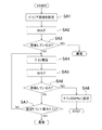
以下に、コントローラ10によるフィードバックゲインの自動調整方法について、図6のフローチャートを参照して具体的に説明すると、まず、スタート後のステップSA1において、加速度センサ6の出力信号が発振しないと考えられる初期値(ゲイン下限値)を設定し、ステップSA2で所定の待ち時間を経た後に(WAIT)、ステップSA3において信号が発振しているかどうか判定する。この判定は、信号の振幅が所定の閾値を超えたかどうかで行うが、発振しても振幅が閾値を超えるまでに或る程度の時間を要する場合もあるので、前記のように待ち時間を設けている。
—Specific Example of
The automatic feedback gain adjustment method by the
前記ステップSA3にて発振している(YES)と判定すれば、発振しないはずの初期値で発振していることになり、何らかの異常が発生していると考えられるから、制御を中止する一方、判定がNOであればステップSA4に進んで、予め設定してある所定のゲイン変化量を加えた新たなゲインを設定する(ゲイン増加)。そして、ステップSA5において前記ステップSA2と同じく所定の待ち時間を経た後に(WAIT)、ステップSA6において前記ステップSA3と同じくセンサ信号が発振しているかどうか判定する。 If it is determined in step SA3 that it is oscillating (YES), it means that it has oscillated with an initial value that should not oscillate, and it is considered that some abnormality has occurred. If determination is NO, it will progress to step SA4 and will set the new gain which added the predetermined gain change amount set beforehand (gain increase). In step SA5, after a predetermined waiting time as in step SA2 (WAIT), it is determined in step SA6 whether the sensor signal is oscillating as in step SA3.
この判定がNOで、発振が起きていない間はステップSA7に進んで、現在のゲインの設定値を、必ず発振の生じると考えられる最大ゲインと比較し(設定ゲイン>最大ゲイン?)、ゲイン設定値が最大ゲインよりも大きければ(YES)異常が発生していると考えられるから、制御を中断する一方、判定がNOであればステップSA4に戻って、再びゲインを増加させた後、前記ステップSA5〜SA7の手順を繰り返す。 If this determination is NO and oscillation does not occur, the process proceeds to step SA7, where the current gain setting value is compared with the maximum gain at which oscillation is considered to occur (setting gain> maximum gain?), And the gain setting is made. If the value is larger than the maximum gain (YES), it is considered that an abnormality has occurred. Therefore, the control is interrupted. On the other hand, if the determination is NO, the process returns to step SA4 and the gain is increased again. Repeat steps SA5 to SA7.
そうして少しずつゲインの値を大きくしながら、加速度センサ6の出力が発振しているかどうかの判定を繰り返し、遂に発振が起きれば、前記ステップSA6において発振している(YES)と判定して、ステップSA8に進む。このときのゲインが、センサ信号の発振し始める臨界ゲインであり、ステップSA8では、臨界ゲインの略50%(略40〜略60%でもよい)の値をフィードバックゲインとして設定し、ゲイン調整を終了する(END)。
Then, while gradually increasing the gain value, the determination as to whether or not the output of the
そうして臨界ゲインに基づいて設定したフィードバックゲインによると、位相交点におけるゲイン余裕が概略6dBくらいになり、制御の安定性を確保しつつ十分な応答性が得られるようになる。つまり、コントローラ10において自動でフィードバックゲインを最適値に調整することができる。このことは、前記実施形態のように、ユーザーの所持する所謂パッシブタイプの除振台に制御ユニットUを取り付けて、簡易的にアクティブ除振台Aを構成する場合に特に有効である。
Thus, according to the feedback gain set based on the critical gain, the gain margin at the phase intersection is about 6 dB, and sufficient response can be obtained while ensuring the stability of the control. That is, the
尚、前記の例では、センサ信号が発振しないような小さな値をゲインの初期値として設定し、臨界ゲインが特定されるまで値を少しずつ増大させるようにしているが、これに限らず、センサ信号が発振するような大きな値を初期値として設定し、その値を少しずつ減少させるようにしてもよい。 In the above example, a small value that does not cause the sensor signal to oscillate is set as the initial value of the gain, and the value is increased little by little until the critical gain is specified. A large value at which the signal oscillates may be set as an initial value, and the value may be decreased little by little.
−調整方法の具体例2−
図7は、フィードバックゲイン調整方法の具体例2を示す。これは、まず、ゲインの上限値及び下限値を設定し、その中央値におけるセンサ信号の発振状況に応じて該中央値を上限値又は下限値に置き換えることにより、それらの間のゲイン範囲を半分にし、これを繰り返すことによってゲイン範囲を臨界ゲインに収束させるものである。
-Specific example of adjustment method 2-
FIG. 7 shows a specific example 2 of the feedback gain adjustment method. This is done by first setting an upper limit value and a lower limit value of the gain, and replacing the median value with the upper limit value or the lower limit value according to the oscillation state of the sensor signal at the median value, thereby halving the gain range between them. By repeating this, the gain range is converged to the critical gain.
具体的に、図示のフローのスタート後のステップSB1,SB2では、初期設定として、センサ信号が発振することはないと考えられるゲイン値を下限値Reg1とし、また、センサ信号が必ず発振すると考えられるゲイン値を上限値Reg2として、それぞれ設定する。続くステップSB3では、前記下限値Reg1及び上限値Reg2からその中央値Reg3を求め、続くステップSB4では、前記中央値Reg3の所定の小数点以下を切り捨てる。 Specifically, in steps SB1 and SB2 after the start of the illustrated flow, as an initial setting, the gain value that the sensor signal is considered not to oscillate is set to the lower limit value Reg1, and the sensor signal is necessarily oscillated. Set each gain value as the upper limit value Reg2. In the subsequent step SB3, the median value Reg3 is obtained from the lower limit value Reg1 and the upper limit value Reg2, and in the subsequent step SB4, the portion below the predetermined decimal point of the median value Reg3 is discarded.
尚、この例では、ゲイン下限値Reg1又は上限値Reg2のいずれかがその中央値Reg3に実質、等しくなるときに、その値を臨界ゲインとするので、その計算速度及び精度は、前記ステップSB4で行うゲイン中央値Reg3の所定小数点以下を切り捨てる桁数により影響を受ける。よって、要求される計算速度および及び精度に合わせて、ゲイン中央値Reg3の小数点以下の切り捨て桁数を決定する(例えば、図の例では小数点2桁以下を切り捨てる)。 In this example, when either the gain lower limit value Reg1 or the upper limit value Reg2 is substantially equal to the median value Reg3, the value is set as a critical gain. Therefore, the calculation speed and accuracy are set in step SB4. It is affected by the number of digits that are rounded off to the specified decimal point of the median gain value Reg3. Therefore, the number of digits after the decimal point of the median gain value Reg3 is determined in accordance with the required calculation speed and accuracy (for example, in the example of the figure, two digits after the decimal point are rounded down).
続いて、ステップSB5において、前記ステップSB4で得られたゲインの値(所定小数点以下を切り捨てた中央値Reg3)が下限値Reg1又は上限値Reg2のいずれかに等しいか、どうか判定する。この判定がNOであれば、ステップSB6に進んで、前記ステップSB4にて得られた値(切り捨て後の中央値Reg3)をフィードバックゲインに設定して、続くステップSB7において所定の待ち時間を経た後、ステップSB8にてセンサ信号が発振しているかどうか判定する。 Subsequently, in step SB5, it is determined whether or not the gain value obtained in step SB4 (the median value Reg3 rounded down after the predetermined decimal point) is equal to either the lower limit value Reg1 or the upper limit value Reg2. If this determination is NO, the process proceeds to step SB6, the value obtained in step SB4 (the median value Reg3 after truncation) is set as the feedback gain, and after a predetermined waiting time in the subsequent step SB7 In step SB8, it is determined whether the sensor signal is oscillating.
そして、センサ信号が発振している(YES)のであればステップSB9へ進み、現在のフィードバックゲインの値Reg3を新たな上限値Reg2とする一方、センサ信号が発振していない(NO)であればステップSB10へ進み、現在のフィードバックゲインの値Reg3を新たな下限値Reg1とする。そうして下限値Reg1又は上限値Reg2を更新した後、前記ステップSB3へ戻って再び中央値Reg3を計算し、ステップSB4にて中央値Reg3の所定の小数点以下を切り捨てた後、前記ステップSB5〜SB10の手順を繰り返す。 If the sensor signal is oscillating (YES), the process proceeds to step SB9, where the current feedback gain value Reg3 is set as a new upper limit value Reg2, while if the sensor signal is not oscillating (NO). Proceeding to step SB10, the current feedback gain value Reg3 is set as a new lower limit value Reg1. Then, after the lower limit value Reg1 or the upper limit value Reg2 is updated, the process returns to the step SB3 to calculate the median value Reg3 again. In step SB4, the median value Reg3 is rounded down to a predetermined decimal point. The procedure of SB10 is repeated.
そうしてゲインの下限値Reg1又は上限値Reg2の更新を繰り返して、図8を参照して後述するようにゲイン範囲を狭めてゆき、その下限値Reg1又は上限値Reg2のいずれかが中央値Reg3と実質、同じになれば(ステップSB5にてYES)、この中央値Reg3が臨界ゲインの値であると判断し、ステップSB11に進んで、前記具体例1のフローのステップSA8と同様に、臨界ゲインの略50%(略40〜略60%でもよい)の値をフィードバックゲインとして設定する。 Then, the lower limit value Reg1 or the upper limit value Reg2 of the gain is repeatedly updated to narrow the gain range as will be described later with reference to FIG. 8, and either the lower limit value Reg1 or the upper limit value Reg2 becomes the median value Reg3. If it becomes substantially the same (YES in step SB5), it is determined that the median value Reg3 is a critical gain value, and the process proceeds to step SB11, and in the same manner as step SA8 in the flow of the specific example 1, A value of approximately 50% (may be approximately 40 to 60%) of the gain is set as the feedback gain.
前記のようにして臨界ゲインが特定される様子を図8に示す。同図において臨界ゲイン値RegCよりも右側の斜線部はセンサ信号が発振する領域であり、臨界ゲイン値RegCよりも左側は発振しない領域である。前記フローのステップSB1及びステップSB2でそれぞれ与えられた初期ゲイン下限値Reg1(0)及び初期ゲイン上限値Reg2(0)の中央値Reg3(0)は発振領域外にあるので、出力信号は発振しない。よって、前記フローのステップSB10により、ゲイン中央値Reg3(0)が新たなゲイン下限値Reg1(1)に設定される。 FIG. 8 shows how the critical gain is specified as described above. In the figure, the hatched portion on the right side of the critical gain value RegC is a region where the sensor signal oscillates, and the left side of the critical gain value RegC is a region where it does not oscillate. Since the median value Reg3 (0) of the initial gain lower limit value Reg1 (0) and the initial gain upper limit value Reg2 (0) given in steps SB1 and SB2 of the flow is outside the oscillation region, the output signal does not oscillate. . Therefore, the gain median value Reg3 (0) is set to the new gain lower limit value Reg1 (1) by step SB10 of the flow.
その新たなゲイン下限値Reg1(1)とゲイン上限値Reg2(0)との中央値Reg3(1)は、図示のように発振領域内にあるので、出力信号は発振し、そのゲイン中央値Reg3(1)は新たなゲイン上限値Reg2(1)に設定される(ステップSB9)。こうして、ゲイン下限値Reg1とゲイン上限値Reg2との間のゲイン範囲を制御サイクル毎に半分に絞って、臨界ゲイン値RegCまで収束させるようにしているので、この臨界ゲイン値RegCを前記実施例1に比べて短時間で、且つ高い精度で特定することができる。 Since the median value Reg3 (1) of the new gain lower limit value Reg1 (1) and gain upper limit value Reg2 (0) is within the oscillation region as shown in the figure, the output signal oscillates and its gain median value Reg3 (1) is set to a new gain upper limit value Reg2 (1) (step SB9). Thus, the gain range between the gain lower limit value Reg1 and the gain upper limit value Reg2 is reduced to half in every control cycle so as to converge to the critical gain value RegC. It is possible to specify with high accuracy in a short time as compared with.
(他の実施形態)
本発明に斯かる精密除振台Aや制振ユニットUの構成は、前記した実施形態のものに限定されず、それ以外の種々の構成も包含する。すなわち、例えば前記実施形態の精密除振台Aは、定盤1を空気ばね2,2,…により支持するようにしているが、この空気ばね2に代えて空気以外の気体を封入した気体ばねを用いることもできる。また、コイルばね等、気体ばね以外のばね要素を用いることも可能である。
(Other embodiments)
The configurations of the precision vibration isolation table A and the vibration damping unit U according to the present invention are not limited to those of the above-described embodiment, and include various other configurations. That is, for example, in the precision vibration isolation table A of the above embodiment, the
また、そうして除振台を用いて設置された機器Dだけでなく、より簡易な手法で設置された機器にも前記制振ユニットUを取り付けて、その振動を抑えることができる。 In addition, the vibration control unit U can be attached not only to the device D installed using the vibration isolation table but also to a device installed by a simpler method, and the vibration can be suppressed.
また、前記実施形態の制御ユニットUでは、図3に示すように、除振対象(定盤1及び機器D)の加速度z″をフィードバックして、可動質量4の駆動制御を行うようにしているが、これに限るものではなく、例えば図9に示すように、基礎側に配設した床上加速度センサ6’からの信号に基づく除振フィードフォワード制御を付加したり、制振ユニットUに配置した位置センサ9からの信号に基づくフィードバック制御を付加したりすることもできる。
In the control unit U of the above embodiment, as shown in FIG. 3, the acceleration z ″ of the vibration isolation target (the
すなわち、床上加速度センサ6’からの信号に基づいて、空気ばね2を介し除振対象に伝達される振動を減殺するような制御力が発生するように、リニアモータ5によって可動質量4を駆動すれば、除振性能をより一層、高めることができる。
That is, the movable mass 4 is driven by the
また、制振ユニットUのケース3に配設した位置センサ9によって可動質量4の位置を検出し、例えば中立位置からの変位量に応じて可動質量4を駆動するようにすれば、この駆動力によって制振ユニットUの振動系(主系に対する付加振動系)のばね定数を見かけ上、変えることができ、その固有振動数を最適化することも可能になる。
Further, if the position of the movable mass 4 is detected by the position sensor 9 disposed in the
さらに、前記のようなフィードバック制御は、前記実施形態に例示した所謂古典制御の手法によるものに限らず、例えばLQ制御やH∞制御等、現代制御の手法によっても実現可能である。 Further, the feedback control as described above is not limited to the so-called classical control method exemplified in the above embodiment, and can be realized by a modern control method such as LQ control or H∞ control.
以上、説明したように、本発明に係るアクティブ除振装置によると、制振機構によって除振対象物に正確な制御力を安定的に加えることができるので、例えば半導体関連の装置や電子顕微鏡等の精密機器を搭載する精密除振台に好適である。 As described above, according to the active vibration isolation device of the present invention, an accurate control force can be stably applied to the vibration isolation object by the vibration suppression mechanism. For example, a semiconductor-related device, an electron microscope, or the like It is suitable for a precision vibration isolation table equipped with the above precision equipment.
A 精密除振台(アクティブ除振装置)
D 機器(除振対象物、制振対象物)
U 制振ユニット(制振機構)
1 定盤(除振対象物)
2 空気ばね(ばね要素)
3 制振ユニットのケース
4 可動質量
40 本体部
41 軸部材(軸部)
5 リニアモータ(アクチュエータ)
6 加速度センサ(振動センサ)
7 板ばね(連結部材)
7’ 積層弾性体(連結部材)
8 コイルばね
9 位置センサ
10 コントローラ
A Precision vibration isolation table (active vibration isolation device)
D equipment (object to be vibration-isolated, damping target)
U Damping unit (damping mechanism)
1 Surface plate (object for vibration isolation)
2 Air spring (spring element)
3 Case of damping unit 4
5 Linear motor (actuator)
6 Acceleration sensor (vibration sensor)
7 Leaf spring (connecting member)
7 'Laminated elastic body (connecting member)
8 Coil spring 9
Claims (7)
前記制振機構は、可動質量と、前記除振対象物に取り付けられて、前記可動質量を前記所定方向に駆動し、その反力を当該除振対象物に作用させるアクチュエータと、を備え、
前記可動質量には前記所定方向の両側にそれぞれ延びる軸部が取り付けられ、この軸部の両端部が各々、軸心方向の移動を許容し且つ軸心に直交する方向の移動を規制する連結部材によって、前記除振対象物に連結され、
前記連結部材は、内周縁部が前記軸部の外周面に連結された環状の板バネからなることを特徴とするアクティブ除振装置。 An active vibration isolator that attaches a vibration control mechanism to a vibration isolation object elastically supported with respect to a foundation and adds a control force that attenuates vibration in a predetermined direction,
The vibration damping mechanism includes a movable mass and an actuator that is attached to the vibration isolation object, drives the movable mass in the predetermined direction, and causes the reaction force to act on the vibration isolation object.
The movable mass is attached with shaft portions extending on both sides in the predetermined direction, and both end portions of the shaft portions each allow movement in the axial direction and restrict movement in a direction perpendicular to the axial center. by being connected to the object to be vibration-isolated,
The connecting member is an active anti-vibration apparatus is characterized in Rukoto such that the inner peripheral edge of an annular leaf spring which is connected to the outer peripheral surface of the shaft portion.
前記振動センサからの信号を受けて、制振機構のアクチュエータの作動を制御するコントローラを備える、請求項1〜3のいずれか1つに記載のアクティブ除振装置。 The vibration isolation object is provided with a vibration sensor for detecting its vibration state,
Receiving a signal from the vibration sensor, a controller for controlling the operation of the actuator of the damper, the active anti-vibration apparatus according to any one of claims 1-3.
コントローラは、前記位置センサからの信号を受けて、前記可動質量の位置を加味してアクチュエータの作動を制御するように構成されている、請求項4に記載のアクティブ除振装置。 The vibration control mechanism is provided with a position sensor for detecting the position of the movable mass in the moving direction,
The active vibration isolator according to claim 4 , wherein the controller is configured to receive the signal from the position sensor and control the operation of the actuator in consideration of the position of the movable mass.
前記制振対象物に取り付けられるケースと、
可動質量と、
前記ケースに固定され、前記可動質量を前記所定方向に駆動して、その反力を当該ケースを介して前記制振対象物に作用させるアクチュエータと、を備え、
前記可動質量には前記所定方向の両側にそれぞれ延びる軸部が設けられ、この軸部の両端部が各々、軸心方向の移動を許容し且つ軸心に直交する方向の移動を規制する連結部材によって、前記ケースに連結され、
前記連結部材は、内周縁部が前記軸部の外周面に連結された環状の板バネからなることを特徴とする制振ユニット。 A vibration control unit that is attached to a vibration control object and adds a control force that reduces vibrations in a predetermined direction.
A case attached to the vibration suppression object;
A movable mass;
An actuator that is fixed to the case, drives the movable mass in the predetermined direction, and causes the reaction force to act on the object to be controlled through the case;
The movable mass is provided with shaft portions extending on both sides in the predetermined direction, and both end portions of the shaft portions allow movement in the axial direction and restrict movement in a direction perpendicular to the axial center. by being connected to the case,
The connecting member, the damping unit has an inner peripheral edge, characterized in Rukoto such an annular leaf spring which is connected to the outer peripheral surface of the shaft portion.
前記振動センサからの信号を受けて、アクチュエータの作動を制御するコントローラを備えている、請求項6に記載の制振ユニット。 The case, together with the coil spring is disposed to support the weight of the moving mass, a vibration sensor for detecting the vibration state of the vibration control object is arranged,
The vibration control unit according to claim 6 , further comprising a controller that receives a signal from the vibration sensor and controls an operation of the actuator.
Priority Applications (1)
| Application Number | Priority Date | Filing Date | Title |
|---|---|---|---|
| JP2007104616A JP4871192B2 (en) | 2007-04-12 | 2007-04-12 | Active vibration isolator and vibration control unit used therefor |
Applications Claiming Priority (1)
| Application Number | Priority Date | Filing Date | Title |
|---|---|---|---|
| JP2007104616A JP4871192B2 (en) | 2007-04-12 | 2007-04-12 | Active vibration isolator and vibration control unit used therefor |
Publications (2)
| Publication Number | Publication Date |
|---|---|
| JP2008261431A JP2008261431A (en) | 2008-10-30 |
| JP4871192B2 true JP4871192B2 (en) | 2012-02-08 |
Family
ID=39984057
Family Applications (1)
| Application Number | Title | Priority Date | Filing Date |
|---|---|---|---|
| JP2007104616A Active JP4871192B2 (en) | 2007-04-12 | 2007-04-12 | Active vibration isolator and vibration control unit used therefor |
Country Status (1)
| Country | Link |
|---|---|
| JP (1) | JP4871192B2 (en) |
Families Citing this family (10)
| Publication number | Priority date | Publication date | Assignee | Title |
|---|---|---|---|---|
| JP2010084814A (en) * | 2008-09-30 | 2010-04-15 | Psc Kk | Vibration eliminating device |
| JP5430916B2 (en) * | 2008-12-02 | 2014-03-05 | 住友重機械工業株式会社 | Reaction force processing mechanism, stage device provided with the reaction force processing mechanism, and semiconductor inspection device provided with the stage device |
| JP5439082B2 (en) * | 2009-07-30 | 2014-03-12 | 倉敷化工株式会社 | Mass damper |
| JP5276548B2 (en) * | 2009-08-07 | 2013-08-28 | 倉敷化工株式会社 | Active vibration isolation method and vibration isolation device used therefor |
| JP5453054B2 (en) * | 2009-10-29 | 2014-03-26 | 倉敷化工株式会社 | Control method and control apparatus for active mass damper |
| JP6152001B2 (en) * | 2012-08-03 | 2017-06-21 | キヤノン株式会社 | Active vibration isolator, vibration isolation method, processing apparatus, inspection apparatus, exposure apparatus, and workpiece manufacturing method |
| JP6637840B2 (en) * | 2016-05-30 | 2020-01-29 | 住友理工株式会社 | Active vibration suppression device |
| JP2019218026A (en) * | 2018-06-22 | 2019-12-26 | 株式会社ブリヂストン | Road face state discrimination method and road face state discrimination device |
| CN114607733B (en) * | 2022-02-21 | 2023-06-16 | 华南理工大学 | Movable intelligent structure vibration reduction system and control method thereof |
| CN116577996B (en) * | 2023-07-06 | 2023-10-20 | 华南理工大学 | Movable active control method for vibration of flexible civil structure |
Family Cites Families (3)
| Publication number | Priority date | Publication date | Assignee | Title |
|---|---|---|---|---|
| JPH0776495B2 (en) * | 1983-10-14 | 1995-08-16 | 三菱電機株式会社 | Vibration control device for structures |
| JP2000142396A (en) * | 1998-11-18 | 2000-05-23 | Hitachi Ltd | Rolling stock |
| JP2006002862A (en) * | 2004-06-18 | 2006-01-05 | Hitachi Zosen Corp | Vibration control device of structure |
-
2007
- 2007-04-12 JP JP2007104616A patent/JP4871192B2/en active Active
Also Published As
| Publication number | Publication date |
|---|---|
| JP2008261431A (en) | 2008-10-30 |
Similar Documents
| Publication | Publication Date | Title |
|---|---|---|
| JP4871192B2 (en) | Active vibration isolator and vibration control unit used therefor | |
| JP6466378B2 (en) | Self-tuning tunable mass damper | |
| EP3624316B1 (en) | Electrodynamic actuator and electrodynamic excitation device | |
| JP2013537600A (en) | Cantilever fan | |
| US9673375B2 (en) | Power generator with an electrical component made from inertial mass and control circuit thereof | |
| JP2011530047A (en) | Vibration isolation system designed to remove load forces acting on the actuator | |
| JP2006283966A (en) | Active vibration removing apparatus | |
| TWI695128B (en) | Active inertial damper system and method | |
| JP4940472B2 (en) | Active vibration isolator and vibration damping device | |
| JP2007078122A (en) | Vibration damper | |
| JP5242943B2 (en) | Active vibration isolator | |
| JP2011247314A (en) | Active vibration removing device | |
| KR20170068760A (en) | A vibration absorber | |
| JP4355536B2 (en) | Active vibration control device for vibration isolation table | |
| JP2010127391A (en) | Active vibration controller and actuator used for the same | |
| JP5217217B2 (en) | Damping device and device to be damped provided with damping device | |
| JP4890196B2 (en) | Vibration removal device | |
| JP6792961B2 (en) | Vibration damping device | |
| JP4219162B2 (en) | Active dynamic damper device | |
| JP2007285377A (en) | Vibration damping device | |
| JP5276548B2 (en) | Active vibration isolation method and vibration isolation device used therefor | |
| KR102563403B1 (en) | Transformers and Transformer Arrays | |
| JP2003035335A (en) | Positive vibration-free system | |
| JP4982272B2 (en) | Active vibration isolation mount mechanism | |
| JP2004246661A (en) | Feedback gain automatic adjustment device and method therefor |
Legal Events
| Date | Code | Title | Description |
|---|---|---|---|
| A621 | Written request for application examination |
Free format text: JAPANESE INTERMEDIATE CODE: A621 Effective date: 20100205 |
|
| A977 | Report on retrieval |
Free format text: JAPANESE INTERMEDIATE CODE: A971007 Effective date: 20110324 |
|
| A131 | Notification of reasons for refusal |
Free format text: JAPANESE INTERMEDIATE CODE: A131 Effective date: 20110412 |
|
| A521 | Request for written amendment filed |
Free format text: JAPANESE INTERMEDIATE CODE: A523 Effective date: 20110531 |
|
| A131 | Notification of reasons for refusal |
Free format text: JAPANESE INTERMEDIATE CODE: A131 Effective date: 20110823 |
|
| A521 | Request for written amendment filed |
Free format text: JAPANESE INTERMEDIATE CODE: A523 Effective date: 20110926 |
|
| TRDD | Decision of grant or rejection written | ||
| A01 | Written decision to grant a patent or to grant a registration (utility model) |
Free format text: JAPANESE INTERMEDIATE CODE: A01 Effective date: 20111025 |
|
| A01 | Written decision to grant a patent or to grant a registration (utility model) |
Free format text: JAPANESE INTERMEDIATE CODE: A01 |
|
| A61 | First payment of annual fees (during grant procedure) |
Free format text: JAPANESE INTERMEDIATE CODE: A61 Effective date: 20111118 |
|
| R150 | Certificate of patent or registration of utility model |
Ref document number: 4871192 Country of ref document: JP Free format text: JAPANESE INTERMEDIATE CODE: R150 Free format text: JAPANESE INTERMEDIATE CODE: R150 |
|
| FPAY | Renewal fee payment (event date is renewal date of database) |
Free format text: PAYMENT UNTIL: 20141125 Year of fee payment: 3 |
|
| R250 | Receipt of annual fees |
Free format text: JAPANESE INTERMEDIATE CODE: R250 |
|
| R250 | Receipt of annual fees |
Free format text: JAPANESE INTERMEDIATE CODE: R250 |
|
| R250 | Receipt of annual fees |
Free format text: JAPANESE INTERMEDIATE CODE: R250 |
|
| R250 | Receipt of annual fees |
Free format text: JAPANESE INTERMEDIATE CODE: R250 |
|
| R250 | Receipt of annual fees |
Free format text: JAPANESE INTERMEDIATE CODE: R250 |
|
| R250 | Receipt of annual fees |
Free format text: JAPANESE INTERMEDIATE CODE: R250 |
|
| R250 | Receipt of annual fees |
Free format text: JAPANESE INTERMEDIATE CODE: R250 |
|
| R250 | Receipt of annual fees |
Free format text: JAPANESE INTERMEDIATE CODE: R250 |
|
| R250 | Receipt of annual fees |
Free format text: JAPANESE INTERMEDIATE CODE: R250 |
|
| R250 | Receipt of annual fees |
Free format text: JAPANESE INTERMEDIATE CODE: R250 |