JP2013537600A - Cantilever fan - Google Patents
Cantilever fan Download PDFInfo
- Publication number
- JP2013537600A JP2013537600A JP2013526039A JP2013526039A JP2013537600A JP 2013537600 A JP2013537600 A JP 2013537600A JP 2013526039 A JP2013526039 A JP 2013526039A JP 2013526039 A JP2013526039 A JP 2013526039A JP 2013537600 A JP2013537600 A JP 2013537600A
- Authority
- JP
- Japan
- Prior art keywords
- blade
- cantilever
- fan
- actuator
- clamp
- Prior art date
- Legal status (The legal status is an assumption and is not a legal conclusion. Google has not performed a legal analysis and makes no representation as to the accuracy of the status listed.)
- Pending
Links
- 230000000737 periodic effect Effects 0.000 claims abstract description 30
- 238000009826 distribution Methods 0.000 claims description 8
- 125000004122 cyclic group Chemical group 0.000 claims 1
- 238000006073 displacement reaction Methods 0.000 description 26
- 238000006243 chemical reaction Methods 0.000 description 24
- 239000000047 product Substances 0.000 description 21
- 239000000463 material Substances 0.000 description 17
- 238000013461 design Methods 0.000 description 12
- 230000008901 benefit Effects 0.000 description 7
- 239000012530 fluid Substances 0.000 description 5
- 238000005516 engineering process Methods 0.000 description 4
- 230000006872 improvement Effects 0.000 description 4
- 239000010410 layer Substances 0.000 description 4
- 230000033001 locomotion Effects 0.000 description 4
- 125000006850 spacer group Chemical group 0.000 description 4
- 238000013459 approach Methods 0.000 description 3
- 230000008859 change Effects 0.000 description 3
- 238000001816 cooling Methods 0.000 description 3
- 230000001419 dependent effect Effects 0.000 description 3
- 238000010586 diagram Methods 0.000 description 3
- 230000009977 dual effect Effects 0.000 description 3
- 238000004519 manufacturing process Methods 0.000 description 3
- 238000012986 modification Methods 0.000 description 3
- 230000004048 modification Effects 0.000 description 3
- 230000009467 reduction Effects 0.000 description 3
- 239000012790 adhesive layer Substances 0.000 description 2
- 238000005452 bending Methods 0.000 description 2
- 238000011161 development Methods 0.000 description 2
- 230000018109 developmental process Effects 0.000 description 2
- 238000000605 extraction Methods 0.000 description 2
- 238000000034 method Methods 0.000 description 2
- 238000002156 mixing Methods 0.000 description 2
- 230000004044 response Effects 0.000 description 2
- 238000000926 separation method Methods 0.000 description 2
- 238000012546 transfer Methods 0.000 description 2
- 238000005054 agglomeration Methods 0.000 description 1
- 230000002776 aggregation Effects 0.000 description 1
- 238000004458 analytical method Methods 0.000 description 1
- 238000003491 array Methods 0.000 description 1
- 230000001580 bacterial effect Effects 0.000 description 1
- 239000007795 chemical reaction product Substances 0.000 description 1
- 230000003247 decreasing effect Effects 0.000 description 1
- 229920001971 elastomer Polymers 0.000 description 1
- 239000000806 elastomer Substances 0.000 description 1
- 239000007789 gas Substances 0.000 description 1
- 238000000227 grinding Methods 0.000 description 1
- 230000036541 health Effects 0.000 description 1
- 238000001746 injection moulding Methods 0.000 description 1
- 238000003475 lamination Methods 0.000 description 1
- 239000002184 metal Substances 0.000 description 1
- 230000010355 oscillation Effects 0.000 description 1
- 239000002245 particle Substances 0.000 description 1
- 239000013618 particulate matter Substances 0.000 description 1
- 230000035699 permeability Effects 0.000 description 1
- 239000004033 plastic Substances 0.000 description 1
- 229920001690 polydopamine Polymers 0.000 description 1
- 230000008569 process Effects 0.000 description 1
- 238000003672 processing method Methods 0.000 description 1
- 230000002441 reversible effect Effects 0.000 description 1
- 238000005549 size reduction Methods 0.000 description 1
- 239000000243 solution Substances 0.000 description 1
- 238000001228 spectrum Methods 0.000 description 1
- 239000000126 substance Substances 0.000 description 1
Images


Classifications
-
- F—MECHANICAL ENGINEERING; LIGHTING; HEATING; WEAPONS; BLASTING
- F04—POSITIVE - DISPLACEMENT MACHINES FOR LIQUIDS; PUMPS FOR LIQUIDS OR ELASTIC FLUIDS
- F04D—NON-POSITIVE-DISPLACEMENT PUMPS
- F04D19/00—Axial-flow pumps
- F04D19/002—Axial flow fans
-
- F—MECHANICAL ENGINEERING; LIGHTING; HEATING; WEAPONS; BLASTING
- F04—POSITIVE - DISPLACEMENT MACHINES FOR LIQUIDS; PUMPS FOR LIQUIDS OR ELASTIC FLUIDS
- F04D—NON-POSITIVE-DISPLACEMENT PUMPS
- F04D33/00—Non-positive-displacement pumps with other than pure rotation, e.g. of oscillating type
-
- G—PHYSICS
- G01—MEASURING; TESTING
- G01P—MEASURING LINEAR OR ANGULAR SPEED, ACCELERATION, DECELERATION, OR SHOCK; INDICATING PRESENCE, ABSENCE, OR DIRECTION, OF MOVEMENT
- G01P15/00—Measuring acceleration; Measuring deceleration; Measuring shock, i.e. sudden change of acceleration
- G01P15/02—Measuring acceleration; Measuring deceleration; Measuring shock, i.e. sudden change of acceleration by making use of inertia forces using solid seismic masses
- G01P15/08—Measuring acceleration; Measuring deceleration; Measuring shock, i.e. sudden change of acceleration by making use of inertia forces using solid seismic masses with conversion into electric or magnetic values
- G01P15/09—Measuring acceleration; Measuring deceleration; Measuring shock, i.e. sudden change of acceleration by making use of inertia forces using solid seismic masses with conversion into electric or magnetic values by piezoelectric pick-up
- G01P15/0922—Measuring acceleration; Measuring deceleration; Measuring shock, i.e. sudden change of acceleration by making use of inertia forces using solid seismic masses with conversion into electric or magnetic values by piezoelectric pick-up of the bending or flexing mode type
-
- H—ELECTRICITY
- H10—SEMICONDUCTOR DEVICES; ELECTRIC SOLID-STATE DEVICES NOT OTHERWISE PROVIDED FOR
- H10N—ELECTRIC SOLID-STATE DEVICES NOT OTHERWISE PROVIDED FOR
- H10N30/00—Piezoelectric or electrostrictive devices
- H10N30/20—Piezoelectric or electrostrictive devices with electrical input and mechanical output, e.g. functioning as actuators or vibrators
- H10N30/204—Piezoelectric or electrostrictive devices with electrical input and mechanical output, e.g. functioning as actuators or vibrators using bending displacement, e.g. unimorph, bimorph or multimorph cantilever or membrane benders
- H10N30/2041—Beam type
- H10N30/2042—Cantilevers, i.e. having one fixed end
-
- H—ELECTRICITY
- H10—SEMICONDUCTOR DEVICES; ELECTRIC SOLID-STATE DEVICES NOT OTHERWISE PROVIDED FOR
- H10N—ELECTRIC SOLID-STATE DEVICES NOT OTHERWISE PROVIDED FOR
- H10N30/00—Piezoelectric or electrostrictive devices
- H10N30/50—Piezoelectric or electrostrictive devices having a stacked or multilayer structure
Abstract
一方の端部においてクランプ留めされたカンチレバーブレードを備えるカンチレバーファンを開示する。このファンは、ブレードに周期的な力を加え、その結果ブレードの周期的なたわみを生じるアクチュエータを備える。

Description
本出願は、概して空気を移動させるための、より具体的には熱管理における用途および混合用途において空気を移動させるためのファン技術に関する。 The present application relates generally to fan technology for moving air, more specifically for moving air in thermal management and mixing applications.
熱伝達用途のために空気を移動させる回転ファンは、電子機器熱管理における普遍的な冷却解決法である。電子製品における電力密度の高まりによって、流量を改善すること、サイズを縮小すること、寿命を延ばすこと、ノイズおよび振動を抑えること、電力消費を減らすことが、回転ファン技術に対して要求されている。この相反する要求の一覧のうち、最も難易度が高いのは長い寿命と思われる。HBLED照明等の新製品は最長で10年間のファン寿命を必要とし得るが、回転ファンで使用されるベアリングは典型的に3年以下の連続使用しか提供しない。 A rotating fan that moves air for heat transfer applications is a universal cooling solution in electronic thermal management. Increasing power density in electronic products requires improved fan flow, reduced size, extended lifetime, reduced noise and vibration, and reduced power consumption for rotating fan technology. . Of this list of conflicting requirements, the longest lifetime seems to be the most difficult. While new products such as HBLED lighting may require up to 10 years of fan life, bearings used in rotating fans typically provide only 3 years or less of continuous use.
カンチレバーファンは、典型的に回転ファンの寿命を制限するコンポーネントであるベアリングを除外できるという利点を有する。この利点にも関わらず、カンチレバーファンは、その他の多くの産業上の要件に達していないため、それらの開発に専念してきた30年間の間にほとんど商業化されてこなかった。例えば、従来のカンチレバーファンは、カンチレバーブレードの安定性および静かな動作のために必要とされる長さ 対 幅の比が大きいために、スモールフォームファクタにおいて回転ファンに相当する流量を提供できない。 Cantilever fans have the advantage that they can eliminate bearings, which are components that typically limit the life of rotating fans. Despite this advantage, cantilever fans have rarely been commercialized during the 30 years that have been devoted to their development, as they have not met many other industrial requirements. For example, conventional cantilever fans cannot provide a flow equivalent to a rotating fan in a small form factor due to the large length to width ratio required for cantilever blade stability and quiet operation.
また、ほぼ全てのカンチレバーファン開発が、ブレード作動形態としての圧電積層に焦点を当ててきたように思われ、PZT等のこれらの材料は、鉛を含む。鉛を含む材料を使用することに伴う不利益は多数あり、製造における健康および安全性リスク、ならびにそれに関連する許可およびコンプライアンスの問題等があり、これはPZT材料の高いコストの一因となる。さらに、鉛等の有害な材料を含む製品は、有害な材料を含まない代替製品と比べて顧客に受け入れられにくいであろう。 Also, almost all cantilever fan developments seem to have focused on piezoelectric lamination as a blade working form, and these materials such as PZT contain lead. There are many disadvantages associated with the use of lead-containing materials, including health and safety risks in manufacturing, and related licensing and compliance issues, which contribute to the high cost of PZT materials. In addition, products that contain harmful materials such as lead will be less acceptable to customers than alternative products that do not contain harmful materials.
さらに、積層PZTアクチュエータは、それらの動作のために高電圧を必要とする。これらの高電圧は、ほとんどの製品OEMにとって好ましくない。多層積層を使用して、電圧要件を低くし得るが、これらの積層は製造上の複雑さおよびコストを高める。多層積層は、振動を相殺するためにダブルカンチレバーが使用される場合には非常に高い製造公差を必要とする。なぜなら各ブレードの共振周波数がきっちりと調和しなければならないからである。積層の各層は、非常に薄く切断されたPZTおよび接着層を含む。その結果、調和したブレードを製造するのに必要とされる精密さは製品の層の数と共に高まり、積層圧電アクチュエータの高いコストを高める。 Furthermore, laminated PZT actuators require high voltages for their operation. These high voltages are undesirable for most product OEMs. Multi-layer stacks can be used to lower voltage requirements, but these stacks increase manufacturing complexity and cost. Multi-layer stacks require very high manufacturing tolerances when double cantilevers are used to counteract vibrations. This is because the resonance frequency of each blade must be perfectly matched. Each layer of the laminate includes a very thin cut PZT and an adhesive layer. As a result, the precision required to produce a harmonized blade increases with the number of product layers, increasing the high cost of the laminated piezoelectric actuator.
圧電材料のさらなる不利益は、時間と共にそれらの変換特性が変化し、その結果性能の低下および低振動カンチレバーファンを提供するために必要なデュアルブレード調和の損失を招くことである。変換特性はまた積層接着層の経年劣化に伴っても変化し、同じく性能損失および振動問題を招く。 A further disadvantage of piezoelectric materials is that their conversion characteristics change over time, resulting in reduced performance and the loss of dual blade harmony necessary to provide a low vibration cantilever fan. The conversion characteristics also change with age of the laminated adhesive layer, which also results in performance loss and vibration problems.
上記不利益によって、カンチレバーファンは、コスト効率の良い性能および寿命の延びを提供し得る新しい革新的なファン技術に対する産業界のニーズに対応することができなかった。 Due to the above disadvantages, cantilever fans have failed to meet industry needs for new and innovative fan technologies that can provide cost effective performance and extended life.
本明細書に組み入れられ、本明細書の一部をなす添付の図面は、開示される多様な態様を図示し、明細書の記載と共に本発明の原理を説明する働きをする。図面は以下の通りである。
詳細な説明
産業界のニーズを満たし、これまでの取り組みの限界を克服するために、本出願は、圧電積層アクチュエータの限界を克服し、熱管理および他の空気移動用途において使用される高性能かつコスト効率の良いファン技術をもたらす新しいブレード作動手段を有するカンチレバーファンを開示する。さらに、これらのニーズを満たし、これまでの取り組みの限界を克服するために、新しい作動手段は、カンチレバーファンに動力を与えるための現実的かつ信頼性のあるアクチュエータの使用を可能にし、ファンの寿命問題を解決し、スモールファンフォームファクタにおいて高い流量を可能にし、高い共振特性係数(「Q」)による正弦波に近いブレード運動によって低周波数で動作することによりノイズの低下を可能にし、振動を低くし、およびカンチレバーファンのサイズ/フォームファクタを小さくして、それらを電子機器冷却(実空間が制約された高出力製品)において実用的にする。
DETAILED DESCRIPTION In order to meet the needs of industry and overcome the limitations of previous efforts, this application overcomes the limitations of piezoelectric laminated actuators and provides high performance and use in thermal management and other air transfer applications. A cantilever fan is disclosed having new blade actuation means that provides cost effective fan technology. In addition, to meet these needs and overcome the limitations of previous efforts, the new actuation means allow the use of realistic and reliable actuators to power the cantilever fan and the life of the fan Solves the problem, enables high flow rates in the small fan form factor, enables low noise by operating at low frequencies with blade motion close to a sine wave with high resonance characteristic factor (`` Q ''), and lowers vibration And reducing the size / form factor of the cantilever fans to make them practical in electronic equipment cooling (high power products with constrained real space).
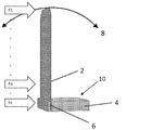
図1は、カンチレバーファンに作動力が加えられ得る位置の範囲の模式図を提供する。図1のカンチレバーファンは、カンチレバーブレード2(以下、「ブレード」と称する)と、クランプ土台4およびクランププレート6を含むクランプ塊10とを有する。ブレード2は、クランププレート6とクランプ土台4との間に堅くクランプ留めされており、標準的なカンチレバーではクランプ土台4は固定され、ブレード2の他端は、弧8で図示するように基本となる所望のカンチレバーモードで自由に振動する。作動力が加えられ得る通例の位置は二箇所ある:すなわち、(1)ブレードの長さに沿った任意の点に直接加える(これをブレード駆動と称する);および(2)ブレードをクランプ留めしている塊に直接に直接加える(これをクランプ駆動と称する)。いずれの場合においても、ファンは、周期的で、かつ基本となる所望のカンチレバーモードを少なくとも部分的に引き起こすのに適した周波数を有する作動力を生じるアクチュエータを備える。一般的に、好ましいカンチレバーモードは、所与の入力電力レベルに対して最大幅の振動弧を提供する(図1の弧8を参照)。当業者に公知なように、所望のカンチレバーモードの周波数に等しいかまたは近い駆動周波数において最良の性能および効率が提供されるが、所望のカンチレバーモードにおいては、所望のモードの高調波および低調波である周波数でブレードが励振されてもよく、これら全ての駆動周波数が本発明の範囲内にあると考えられる。
FIG. 1 provides a schematic diagram of the range of positions where an actuation force can be applied to the cantilever fan. The cantilever fan of FIG. 1 has a cantilever blade 2 (hereinafter referred to as “blade”) and a
ブレード駆動
ブレード作動力は、図1において力Flとして図示するようにブレードの先端からブレードクランプラインのすぐ近くまでブレードのどこにでも直接加えることができ、また力Fnとして図示するようにブレード先端とブレードクランプラインとの間の中間位置にも加えることができる。この加力点の連続は力を加えるアクチュエータによる負荷インピーダンスの連続に対応し、ブレードの先端が最も低いインピーダンス点であり、ブレードクランプライン近くの点が最も高いインピーダンスを有する。ブレードの長さに沿ってある様々な点におけるブレードのインピーダンスの正確な値は、特定のブレード設計の関数(function)である。ブレードの長さに沿ってある広範囲にわたる負荷インピーダンスは、所与の点においてアクチュエータの力を加える際のアクチュエータ様式およびトポロジーが異なることを示唆する。ブレードに力を加える場合、クランプ塊10はブレードの先端変位に対して主に不動であると想定している。
Blade drive Blade actuation force can be applied directly anywhere on the blade from the blade tip to the immediate vicinity of the blade clamp line as illustrated as force Fl in FIG. 1 and blade tip and blade as illustrated as force Fn. It can also be added at an intermediate position between the clamp lines. This series of applied points corresponds to a series of load impedances by the actuator that applies the force, with the blade tip being the lowest impedance point and the point near the blade clamp line having the highest impedance. The exact value of the blade impedance at various points along the length of the blade is a function of the particular blade design. The wide range of load impedances along the length of the blade suggests that the actuator mode and topology differ when applying the actuator force at a given point. When a force is applied to the blade, it is assumed that the
ブレード駆動型態様に使用されるアクチュエータ従属コンポーネントは、不動または振動のいずれかに分類され得る。ブレードを作動させる力は、不動コンポーネントと振動コンポーネントとの間で生成される。不動コンポーネントは、ブレードと共に振動しないように配置され、そういう意味でブレードの振動運動に対して実質的に不動である。本明細書で使用する不動という用語は、アクチュエータが絶対に不動であるということを意味しない。なぜなら、ブレード反動力によっていくらかは振動するかもしれないからである。しかし、アクチュエータコンポーネントは、ブレードには接続されず、代わりに、ファンの不動または非振動コンポーネントに接続されるため、ブレードのクランプ留めされた端部に対してほぼ不動である。振動コンポーネントはブレードに取り付けられるため、ブレードと共に振動する。例えば、図3の態様において、電機子30は不動アクチュエータコンポーネントであり、ブレード22および24は振動アクチュエータコンポーネントとして作用する。別の例としては、図24において、電機子は不動アクチュエータコンポーネントであり、ブレード12および裏当てプレート228は振動アクチュエータコンポーネントである。
Actuator dependent components used in blade driven aspects can be classified as either stationary or vibrating. The force to actuate the blade is generated between the stationary component and the vibrating component. The immobile component is arranged so as not to vibrate with the blade and in that sense is substantially immobile with respect to the vibrational movement of the blade. The term stationary as used herein does not mean that the actuator is absolutely stationary. This is because some blade vibration may cause some vibration. However, the actuator component is not connected to the blade, but instead is connected to the stationary or non-vibrating component of the fan, so it is substantially stationary relative to the clamped end of the blade. Since the vibrating component is attached to the blade, it vibrates with the blade. For example, in the embodiment of FIG. 3,
不動および振動コンポーネントの両方のアクチュエータ設計は、カンチレバーブレードに結合されかつブレードの振動に対して不動なアクチュエータコンポーネントを全く持たない従来技術デバイスにおいて使用される積層圧電ベンダーアクチュエータとは、明らかに異なる。ブレードと共に振動しないコンポーネントを有するアクチュエータにより、開示しているカンチレバーファンの多くの利点が可能になる。 The actuator design for both stationary and vibrating components is clearly different from stacked piezoelectric bender actuators used in prior art devices that are coupled to a cantilever blade and do not have any stationary actuator component for blade vibration. Actuators having components that do not vibrate with the blades enable many of the advantages of the disclosed cantilever fans.
図2は、そのようなブレード駆動型態様の一つを図示しており、ここでは、ブレード12のクランプラインから距離Dにある位置において電磁力がブレードに加えられる。アクチュエータは、電機子16に巻かれている、ブレードの振動に対して不動であるコイル14を含む。空隙18が電機子16とブレード12との間にある。コイルに電圧を与えると、空隙18に生じる引力となる電磁力が、電機子16に向かってブレードを引っ張る。コイル14を駆動するために多数の異なる電圧波形が使用され得るが、一般的に、波形の周波数は、ブレードにおける基本となるカンチレバーモードを引き起こすのに適しかつ所与の用途に必要とされる性能をもたらすものである。正弦波駆動電圧が使用される場合、力応答はパラメトリックなので、駆動電圧周波数はブレードの共振周波数の半分でなければならない。任意の単極パルス電圧波形が使用される場合、ピーク効率は典型的に50%未満のデューティサイクルにおいてみとめられる。
FIG. 2 illustrates one such blade-driven embodiment, in which electromagnetic force is applied to the blade at a distance D from the clamp line of the
図3は、各ブレードが図2のブレード12と同じアクチュエータトポロジーで駆動されるデュアルブレードカンチレバーファンを図示している。コイル20に電圧を与えた場合、空隙26および28中の電磁力がそれぞれブレード22および24を電機子30に向かって引っ張る。このようにして、周期的なアクチュエータの力が、ブレードが互いと反対に変位するようなブレード22および24の好適なカンチレバーモードを引き起こし、この結果、ブレードの横反動力が相殺される。この力の相殺は、電機子30の振動を低減し、それにより、ファンが搭載される製品またはシステムに伝達される振動を低減する。
FIG. 3 illustrates a dual blade cantilever fan where each blade is driven with the same actuator topology as the
図2および3に示すアクチュエータは、ファンブレードのクランプ留めされた端部に近接するように配置される。本発明の範囲は、ブレードの長さに沿ったあらゆる点において作動力を提供することを包含する。例えば、図2において、距離Dは長くされても短くされてもよく、Dの厳密な値は具体的な設計要件に応じて選択され得る。例えば、設計要件によっては、作動力がブレード先端に加えられ得る。アクチュエータは、クランプ土台の反対側に配置されたファンハウジングの一部に搭載され得る。このような態様では、ハウジングの配置は、アクチュエータおよびクランプ土台を構造的に支持したまま、ブレードが振動することおよびファンから気流が出ることを可能にするものである。同様に、ブレード先端とクランプ留めされた端部との間の位置においてブレードに作動力を加えるために、アクチュエータがブレードの長さに沿ったその他の点に搭載され得る。 The actuator shown in FIGS. 2 and 3 is positioned proximate to the clamped end of the fan blade. The scope of the present invention includes providing an actuation force at any point along the length of the blade. For example, in FIG. 2, the distance D may be increased or decreased, and the exact value of D can be selected according to specific design requirements. For example, depending on the design requirements, an actuation force can be applied to the blade tip. The actuator may be mounted on a portion of the fan housing located on the opposite side of the clamp base. In such an embodiment, the arrangement of the housing allows the blades to vibrate and air flow out of the fan while structurally supporting the actuator and clamp base. Similarly, an actuator can be mounted at other points along the length of the blade to apply an actuation force to the blade at a location between the blade tip and the clamped end.
クランプ駆動
図1において力Fcとして図示しているように、クランプ塊10に周期的な力を加えて、ブレード2の好適なカンチレバーモードを引き起こす手段としてクランプ塊10の周期的振動を生成してもよい。このモードでブレードを駆動する場合、ブレードの先端変位はクランプ塊10の変位の数百倍以上のものであり得る。その結果、クランプ塊は非常に小さい変位しか必要とせずに、大きなブレード先端たわみを駆動することができる。一般的に、アクチュエータは、ブレードの振動に動力を与え、かつクランプ構造の塊を振動させるのに十分な力を提供しなければならない。
Clamp drive As shown in Fig. 1 as force Fc, a periodic force can be applied to the
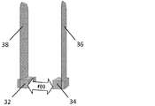
図4は、デュアルブレードカンチレバーファンに対するクランプ塊駆動アプローチを描いている模式図であり、アクチュエータの周期的な力F(t)がブレード38および36のそれぞれのクランプ塊32および34の間に加えられている。このようにして、ブレード38および36のカンチレバーモードが引き起こされて、ブレード38および36が互いと反対方向に変位し、その結果それらの横反動力が相殺される。
FIG. 4 is a schematic diagram depicting the clamp mass drive approach for a dual blade cantilever fan, where the actuator's periodic force F (t) is applied between the
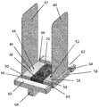
図5は、図4に模式的に図示されたクランプ駆動アプローチの態様を図示している。ブレード40および42はそれぞれクランプ塊52および44によってクランプ留めされている。クランプ塊52は、クランプ土台54と、クランププレート58と、E型電機子56とを含む。クランプ塊44は、クランプ土台46と、クランププレート50と、E型電機子48とを含む。アクチュエータバネ66および64は、クランプ塊44および52をそれぞれバネのブラケット60および62に弾性的に接続する。アクチュエータバネ66および64は、ブレードと一体化した部分であってもよいし、またはブレードの厚みとは異なる厚みのバネ材料を得るために別個の部分であってもよい。バネのブラケット60および62はコイル支持体68によって互いと堅く接続されており、該コイル支持体68は図6の断面図に示すように不動コイル70も支持する。動作の際は、ブレード40および42の所望の共振周波数において周期的な電流波形がコイル70に与えられ、これにより電機子48と56との間に周期的引力が生じ、これによりバネ66および64を支えとしてクランプ塊44および52が互いと反対に振動する。そして、クランプ塊44および52の振動がブレード42および40の所望のカンチレバーモードを引き起こす。バネ66および64の剛性は、磁力を加えている間にそれらに蓄えられるエネルギーが、動作周波数に適した時間周期で電機子を再度押し離すように、選択される。ブレード先端 対 クランプ塊の変位比が非常に高いクランプ駆動型モードで主に動作するために、クランプ塊44および52の変位がほんのわずかとなるようにバネ66および64は十分に堅くなければならない。クランプ塊44および52ならびにブレード42および40の反対方向の横振動により、それぞれの反動力が相殺され、その結果、ファンが搭載される製品またはシステムへ伝達される振動が低減される。バネのブラケット60および62、ならびにコイル支持体68は一番振動が少ないコンポーネントであるため、最も良好なファン搭載地点を提供する。図1の弧8に示すように、ブレードの振動は、ファンクランプ土台に軸方向の反動力を伝達する軸方向成分(axial component)も有する。これらの軸方向の反動力は、図5のファンにおいてブラケット60および62、ならびにコイル支持体68をいくらか振動させるかもしれない。弾性的に搭載することで、ファンが搭載される製品またはシステムからこの振動を絶ってもよい。
FIG. 5 illustrates an embodiment of the clamp drive approach schematically illustrated in FIG.
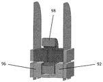
図7は、別のクランプ駆動型態様を図示している。ブレード72および74はそれぞれクランプ塊76および82でクランプ留めされている。クランプ塊76は、クランププレート78と、E型電機子80とを含んでいる。クランプ塊82は、クランププレート86と、E型電機子84とを含んでいる。ブレード72および74は、クランプ塊76および82を経由してファン土台88まで延伸している。ファン土台88は、クランププレート94および90と、図8の断面図に示すように不動コイル98をクランプ留めしているコイルクランプ92および96とを含んでいる。アクチュエータバネは、ブレードと一体化され得る。例えば、ブレード72および74のうち、クランプ塊76および82のそれぞれとファン土台88との間にわたる部分はそれぞれアクチュエータバネ100および102の働きをし、図5のバネ66および64と同じ機能を果たし得る。動作の際には、ブレード72および74の所望の共振周波数における周期的電流波形をコイル98に与え、これにより電機子80と84との間に周期的引力が生じ、これによりクランプ塊76および82がバネ100および102を支えとして互いと反対に振動する。そして、クランプ塊76および82の振動がブレード72および74の所望のカンチレバーモードを引き起こす。バネ100および102の剛性は、磁力を加えている間にそれらに蓄えられるエネルギーが、動作周波数に適した時間周期で電機子を再度押し離すように、選択される。ブレード先端 対 クランプ塊の変位比が非常に高いクランプ駆動型モードで主に動作するために、クランプ塊76および82の変位がほんのわずかとなるようにバネ100および102は十分に堅くなければならない。クランプ塊76および82、ならびにブレード72および74の反対方向の横振動により、それぞれの反動力が相殺され、その結果、ファンが搭載される製品またはシステムへ伝達される振動が低減される。ファン土台88は一番振動が少ないコンポーネントであるため、最も良好なファン搭載地点を提供する。図1の弧8に示すように、ブレード72および74の振動は、軸方向の反動力をファンクランプ土台に伝達する軸方向成分も有する。これらの軸方向の反動力は、ファン土台88をいくらか振動させるかもしれない。弾性的に搭載することで、ファンが搭載される製品またはシステムからこの振動を絶ってもよい。
FIG. 7 illustrates another clamp drive embodiment.
風量および圧力
従来技術のカンチレバーファンは気流を作ることが可能であるが、同様のサイズの回転ファンと比べて非常に低い圧力においてのみで可能である。この圧力性能の乏しさは、一部には、カンチレバーファンを通る空気の逆流に対する抵抗が低いことに起因する。カンチレバーファンの周りにハウジングを配することで、その圧力性能が改善される。しかし、ハウジングは問題の主因に対処するものではない。この比較的乏しい圧力性能の主な原因は、ファンブレードがその変位弧の特定の地点を通る振動期間部分の間以外は、カンチレバーファンを通る逆流路が制限されていないことである。言い換えると、特定の地点でのブレードの滞留時間は、その地点でブレードが空気を実際に前に移動させている場合、ブレード振動期間全体のほんの小さな部分でしかない。残りの振動期間の間、下流流れ抵抗の結果としてのカンチレバーファンを通る空気の逆流に対する抵抗は低い。
Airflow and Pressure Prior art cantilever fans are capable of producing airflow, but only at very low pressures compared to similarly sized rotating fans. This lack of pressure performance is due, in part, to low resistance to backflow of air through the cantilever fan. By placing the housing around the cantilever fan, its pressure performance is improved. However, the housing does not address the main cause of the problem. The main cause of this relatively poor pressure performance is that the reverse flow path through the cantilever fan is not restricted except during the portion of the vibration period where the fan blade passes through a specific point in its displacement arc. In other words, the dwell time of a blade at a particular point is only a small part of the entire blade vibration period if the blade is actually moving air forward at that point. During the remaining oscillation period, the resistance to backflow of air through the cantilever fan as a result of downstream flow resistance is low.
図9に示す態様は、第二のカンチレバーファンブレードセットを加えることによりカンチレバーファンの風量および圧力性能がどのように改善され得るかの一例である。アクチュエータが図9中のブレード104、106、108および110のカンチレバーモードを引き起こす様式は、図2および3のファンと同一である。動作の際、第一の周期的電流波形がコイル112および114の両方を駆動し、第二の周期的電流波形がコイル116および118を駆動し、該第一および第二の電流波形は互いに対して180度またはほぼ180度位相がずらされる。このコイル電流の位相調整によって、第一のブレード対を構成するブレード104および106は互いと反対に振動し、第二のブレード対を構成するブレード108および110も互いと反対に振動する。コイル電流の位相調整はまた、第一のブレード対の位相を第二のブレード対とずらして、第一のブレード対のブレード先端が互いと最も近い時に、第二の対のブレード先端は互いと最も離れているようにする。このようにして、二対のブレードが全て衝突することなく同じ空間で揺れ、その結果ブレード滞留時間がより長くなり、下流流れ抵抗の存在下における空気の逆流が減少する。
The embodiment shown in FIG. 9 is an example of how the airflow and pressure performance of the cantilever fan can be improved by adding a second cantilever fan blade set. The manner in which the actuator causes the cantilever mode of
ブレードが振れる空間を共有するこの方法および上記利点は、アレイ状に配置された任意の枚数のブレードに拡大適用することができる。ブレードのアレイを備えるファンの態様の一例を図10に模式的に図示しており、これは各ブレードが矢印で示す方向で均衡点を通る瞬間の、ブレードの瞬間的な上面図を示す(すなわち、ブレードの平面を見下ろしている)。任意の数の異なる作動スキームが、ファンアレイの個別のブレードに対して使用できる。アレイ中のブレードの土台に孔またはポートを加えて、気流がアレイを通るようにしてもよい。このアプローチを使用して、パンケーキ型回転ファンに似た総アスペクト比を有するカンチレバーファンアレイを得てもよい。同様の位相のカンチレバーブレードが、変位空間を共有しないセクションにおいて一緒のグループにされた、その他のアレイも使用できる。 This method of sharing the space in which the blades swing and the above advantages can be extended to any number of blades arranged in an array. An example of an embodiment of a fan with an array of blades is schematically illustrated in FIG. 10, which shows an instantaneous top view of the blades at the moment each blade passes through a balance point in the direction indicated by the arrow (i.e. , Looking down on the plane of the blade). Any number of different operating schemes can be used for the individual blades of the fan array. Holes or ports may be added to the foundation of the blades in the array to allow airflow through the array. This approach may be used to obtain a cantilever fan array having a total aspect ratio similar to a pancake-type rotating fan. Other arrays can also be used where similar phase cantilever blades are grouped together in sections that do not share displacement space.
風量 対 ファンサイズ
従来技術のカンチレバーファンは同じ流量を提供する回転ファンよりも著しく大きく、典型的な熱管理用途には非実用的である。カンチレバーブレードは、従来技術のカンチレバーファンのサイズを決定するコンポーネントである。しかし、性能、サイズおよびノイズの産業上の要件を満たすことは、サイズ縮小およびファンを使用する実際の製品とより適合しているフォームファクタを得るために、従来技術のカンチレバーファンでは克服できない相反する要求を生じる。
Airflow vs. fan size Prior art cantilever fans are significantly larger than rotating fans that provide the same flow rate and are impractical for typical thermal management applications. The cantilever blade is a component that determines the size of a prior art cantilever fan. However, meeting the industrial requirements of performance, size and noise conflicts with prior art cantilever fans in order to obtain a form factor that is more compatible with actual products that use size reduction and fans Make a request.
カンチレバーファンが生じる流量は、ブレードのサイズ(ブレードがどれだけ空気を移動できるか)、ブレード周波数、ブレードストロークおよびブレード先端速度に比例する。ブレード幅を大きくすることで所与の長さのブレードに対してより多くの風量を得ることができるが、ブレード幅を大きくするとブレードの不安定さによるノイズが増える。静かな動作のためには、より高次の機械的なブレード高調波を伴わない低い動作周波数および正弦波振動を必要とする。正弦波振動の生成のためには、ブレードの基本となるカンチレバーモードとそれより高次のモードとの間の振動周波数を大きく分離する必要がある。従来技術のファンでは、この分離は、従来、良好なモード分離のために、長さ 対 幅(L/W)比が大きい長方形のブレードを設計することによって達成されており、これは、より多くの風量を得るためにブレードを幅広くすることの妨げになってきた。また、ノイズを少なくするために低い周波数での動作を達成するには、ブレード長さを伸ばさなければならなく、これにより、必ずしも流量を増やすことなくファンのサイズが大きくなる。これらの相反する要件により、従来技術カンチレバーファンは同じ流量の回転ファンよりも著しく大きい。 The flow rate produced by the cantilever fan is proportional to the blade size (how much air the blade can move), blade frequency, blade stroke and blade tip speed. Increasing the blade width can provide more airflow for a given length of blade, but increasing the blade width increases noise due to blade instability. Quiet operation requires low operating frequency and sinusoidal vibration without higher order mechanical blade harmonics. In order to generate sinusoidal vibration, it is necessary to largely separate the vibration frequency between the cantilever mode that is the basis of the blade and the higher-order mode. In prior art fans, this separation has traditionally been achieved by designing a rectangular blade with a large length-to-width (L / W) ratio for better mode separation, which is more It has become a hindrance to widening the blades to obtain the airflow. Also, to achieve low frequency operation to reduce noise, the blade length must be increased, which increases the size of the fan without necessarily increasing the flow rate. Due to these conflicting requirements, prior art cantilever fans are significantly larger than rotating fans of the same flow rate.
ブレード形状および質量分布
本開示は、新しいブレード形状およびブレード質量分布の両方により、性能を改善し、かつカンチレバーファンのサイズを縮小するための手段を提供する。これらは、(1)非常に低いL/Wアスペクト比を可能にし、(2)これらのより幅広いブレードによって高い気流性能をもたらし、かつ(3) 低いL/W比にも関わらず低い周波数の正弦波での変位により静かな動作をもたらす。
Blade Shape and Mass Distribution The present disclosure provides a means to improve performance and reduce cantilever fan size with both new blade shape and blade mass distribution. These enable (1) a very low L / W aspect ratio, (2) high airflow performance with these wider blades, and (3) a low frequency sine despite the low L / W ratio Displacement in the wave brings quiet operation.
図11に示すファンブレード120 は、L/W比がおよそ1であり、好適なカンチレバーモード付近の周波数において密度(dense)モデルスペクトルを有する。その結果、有用な気流を作るのに十分な大きさの変位までカンチレバーモードを駆動すると、その他のモードも引き起こされ、その結果ブザーに似た音質の可聴ノイズレベルを生じ、これはほとんどの熱管理用途のために非常に好ましくない。実用的な熱管理に必要とされるファンのサイズでは、ファンブレード120は静かな動作のためには高すぎる基本カンチレバー周波数も伴ってしまう。
The
質量122がブレードの先端部に結合された図11のファンブレード120を図12に示す。このようなタイプの質量を加えることで、以下の利点が得られる。質量122はブレードの大部分の面積を堅くし、この事は、いくつかの望ましくないモードを無くし、かつ他の望ましくないモードの周波数を引き上げ、その結果基本となるカンチレバーモードにおいて正弦波の動きを生じる。質量122はまた、基本カンチレバー周波数を低くして、非常に短いブレードが低周波数で動作することを可能にする。質量122を加えることによって、ブレード共振における蓄積エネルギーも大きくなり、これはブレードが大きくたわむように駆動するのに必要な電力を少なくして高いエネルギー効率をもたらし、ブレードによって行われ得る流体のなす仕事量(fluid work)を増やしてより高い圧力性能をもたらす。図12、14、16および18に示すような質量負荷ブレードは、上記したのと同じ利点を有し、ブレードの長さを上回るピーク間の(peak-to-peak)先端たわみにおいて安定した静かな動作を維持して、非常にコンパクトなカンチレバーブレードで有意な気流量を可能にし得る。
FIG. 12 shows the
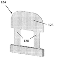
ブレードに別個の質量を加えることなく好適な質量分布を得ることもできる。例えば、図13は、モードを無くして他のモードの周波数を増やすことによって正弦波変位を提供する、別のブレード態様を図示している。ブレード124はパドル126と二本の脚128とを含み、該脚128は主要な曲がり部材であり、パドル124は主な流体仕事を提供する。パドル126は、脚128よりも大きな質量を有するために、脚128と比べていくらかの質量負荷特性を提供する。ブレードの構造によって、改善された質量分布が得られる。
A suitable mass distribution can also be obtained without adding a separate mass to the blade. For example, FIG. 13 illustrates another blade embodiment that provides sinusoidal displacement by eliminating modes and increasing the frequency of other modes. The
また、別個の質量の使用を好適なブレード形状と組み合わせることによって、所望の質量分布を達成することもできる。例えば、図14は、質量130がパドル126に結合された、図13のブレード124を示す。質量130は、共振周波数を低くすると共に、ブレードのQを高めて、ファンの効率を高める。
The desired mass distribution can also be achieved by combining the use of a separate mass with a suitable blade shape. For example, FIG. 14 shows the
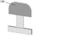
図15は、モードを無くして、他のモードの周波数を増やすことによって正弦波変位を可能にする別のブレード態様を描いている。ブレード132はパドル136および脚134を備え、該脚134は主要な曲がり部材であり、パドル136は主な流体仕事を提供する。パドル136は、脚134よりも大きな質量を有するために、脚134と比べていくらかの質量負荷特性を提供する。
FIG. 15 depicts another blade embodiment that allows sinusoidal displacement by eliminating modes and increasing the frequency of other modes. The
図16は、質量138をパドル132に結合させた、図15のブレード132を示す。質量138は、共振周波数を低くすると共に、ブレードのQを高めて、ファンの効率を高める。
FIG. 16 shows the
図17は、モードを無くして、他のモードの周波数を増やすことによって正弦波変位を可能にする別のブレード態様を図示している。図17において、ブレード140は四枚の個別のブレード142にさらに分割され、これらは全て同じカンチレバー共振周波数を有する。個々のブレード142は高いL/W比を提供するため個々のブレードそれぞれの安定した正弦波振動を作る一方で、四枚のブレード全てが低いL/W比の設置面積に適合する。
FIG. 17 illustrates another blade embodiment that allows sinusoidal displacement by eliminating modes and increasing the frequency of other modes. In FIG. 17, the
図18は、別個の質量144が別個のブレード142に結合した図17のブレード140を示す。質量144はブレード142の共振周波数を同じだけ低減すると共に、ブレード142のQを同じだけ高めて、ファンの効率を高める。
FIG. 18 shows the
図12〜18のブレードのために多くの加工方法があり、これらは当業者には明らかであり、かつ本発明の範囲内にあると考えられる。例えば、パドルは、バネ脚と結合される別個の孤立したコンポーネントであってもよいし、または射出成形方法を使用してバネ脚上に成形されてもよい。ブレードの質量は任意の数の材料からなる孤立したコンポーネントであってもよいし、パドルと一体型にされてもよいし、または単にパドルの厚みを変えることによってパドル自体の一特性としてもよい。 There are many processing methods for the blades of FIGS. 12-18, which will be apparent to those skilled in the art and are considered to be within the scope of the present invention. For example, the paddle may be a separate isolated component that is coupled with the spring leg or may be molded onto the spring leg using an injection molding method. The mass of the blade may be an isolated component of any number of materials, may be integrated with the paddle, or may be a characteristic of the paddle itself by simply changing the thickness of the paddle.
ブレード駆動型ラジアルファン
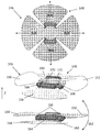
図19は、放射状に方向付けられた気流を提供し、かつ振動相殺が向上した別の態様を図示している。図19において、ブレード146はパドル150および152を含み、ブレード148はパドル154および156を有し、ブレード146はブレード148に対して90度回転されている。ブレード146の中央は磁性コア体164の中央上面に堅く結合しており、ブレード148の中央は磁性コア体164の中央底面に堅く結合している。ブレード146および148は、図2、3および9のファンと同じ様式のアクチュエータで同じように作動される。パドル150および152は、コイル166および168に電圧を与えられた際に対称的な空隙158内で生成される磁力によって作動され、パドル154および156は、コイル170および172に電圧が与えられた際に対称的な空隙160内で生成される磁力によって作動される(第二の空隙160は図面において図示されていない)。動作の際は、ブレード146および148のパドルはZ方向に振動してこれは主に放射方向の気流を作る。振動相殺の好適な態様において、コイル166および168は同じ周期的電流で駆動されてパドル150および152を互いと同相で振動させ、コイル170および172は同じ周期的電流で駆動されてパドル154および156を互いと同相で振動させ、かつコイル166および168を駆動する電流波形はコイル170および172を駆動する電流波形と同相であり、ブレード146のパドルをブレード148のパドルと反対に(位相を180度ずらして)振動させる。
Blade Driven Radial Fan FIG. 19 illustrates another embodiment that provides a radially directed airflow and improved vibration cancellation. In FIG. 19,
図19において、各パドルの先端は弧162と同様の弧で振動し、その結果、各ブレードは、磁性コア体164に作用する放射方向およびZ軸方向の両方の反動力を作る。磁性コア体164は、図19のファンが製品に搭載され得る点である。ファンブレードが対称的であるため、各パドルの放射方向の反動力は放射方向に反対にあるパドルによって相殺され、ブレード146の軸方向の反動力は対向するブレード148の対向する軸方向の反動力によって相殺される。このようにして、放射方向および軸方向の反動力は両方共、動作中にブレードパドルの共振周波数、質量および変位の全てが一致するような程度に相殺される。全ての反動力が相殺されない程度に、磁性コア体164が製品またはシステムに弾性的に取り付けられて、製品またはシステムに振動が伝達されないようにされてもよい。
In FIG. 19, the tip of each paddle oscillates in an arc similar to the
様々な形状およびブレード質量負荷を含む、多数あるブレード設計の任意のものが図19のファンに使用でき、具体的に使用されるブレードは所与の用途の設計要件に基づいて選択され得る。 Any of a number of blade designs can be used for the fan of FIG. 19, including various shapes and blade mass loads, and the blades specifically used can be selected based on the design requirements of a given application.
クランプ駆動型ラジアルファン
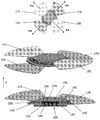
図20は、放射状に方向付けられた気流を提供し、振動相殺が向上した別の態様を図示している。図20のラジアルファンは、クランプ塊198にクランプ留めされた一対のブレード174および180と、クランプ塊200にクランプ留めされた第二のブレード対176および178とを含む。クランプ塊198は、クランプディスク182と、磁性コア190と、コイル194とを含む。クランプ塊200は、クランプディスク184と、磁性コア192と、コイル196とを含む。クランプ塊198はバネ186の中央に堅く結合されており、クランプ塊200はバネ188の中央に堅く結合されている。バネ186および188はそれぞれの周辺において、環状バネスペーサー196によって互いと堅く結合している。バネ186および188はクランプ塊198および200をZ軸方向に振動させる。バネ186および188の剛性は、磁力を加えている間にそれらに蓄えられたエネルギーが、動作周波数に適した時間周期でクランプ塊を再度押し離すように選択される。ブレード先端 対 クランプ塊の変位比が非常に高いクランプ駆動型モードで主に動作するために、バネ186および188は、クランプ塊198および200の変位がわずかしかないように十分に堅くなければならない。
Clamp Driven Radial Fan FIG. 20 illustrates another embodiment that provides radially directed airflow and improved vibration cancellation. The radial fan of FIG. 20 includes a pair of
動作の際、ブレード174、176、178および180はZ方向に振動することで、主に放射方向の気流が作られる。振動相殺の好適な態様において、コイル194および196が同じ周期的電流で駆動されることで、磁性コア190と192との間に生じる磁気引力によってクランプ塊198がクランプ塊200に引き寄せられる。電流の周期性によって、周期的電流の周波数においてクランプ塊が互いと反対に振動する。駆動電流周波数がブレードのカンチレバーモードに等しいかまたは近い場合では、ブレード174および180は同相であるが、ブレード176および178とは位相が180度ずれて振動するように、クランプ塊の振動が全てのブレードカンチレバーモードを引き起こす。各ブレード先端は、図19の弧162と同様の弧で振動することで、各ブレードは、バネスペーサー196に作用する放射方向およびZ軸方向の反動力の両方を作る。バネスペーサー196は図20のファンにおける最小振動点であり、ファンが製品に搭載される地点である。ファンブレードが対称的であるため、ブレード対174および180の放射方向の反動力は互いを相殺し、ブレード対176および178の放射方向の反動力は互いを相殺し、かつブレード対174および180の軸方向の反動力はブレード対176および178の反対方向の軸方向の反動力によって相殺される。このようにして、放射方向および軸方向の反動力の両方は、動作中にブレードの共振周波数、質量および変位の全てが一致するような程度に相殺される。全ての反動力が相殺されない程度に、バネスペーサー196が製品またはシステムに弾性的に取り付けられて、製品またはシステムに振動が伝達されないようにされてもよい。
In operation, the
様々な形状およびブレード質量負荷を含む、多数あるブレード設計の任意のものが図20のファンに使用でき、具体的に使用されるブレードは所与の用途の設計要件に基づいて選択され得る。 Any of a number of blade designs can be used for the fan of FIG. 20, including various shapes and blade mass loads, and the blades specifically used can be selected based on the design requirements of a given application.
アクチュエータの種類
図2〜20に示すアクチュエータトポロジーおよび動作原理は、本発明で使用できる具体的なアクチュエータを図示している。しかし、ブレードの変位に対して不動なコンポーネントおよび本発明で使用し得る多くのアクチュエータ改善を有するその他の多くの種類のアクチュエータも存在し、当業者は思い付くであろう。これらは全て本発明の範囲内にあると考える。
Actuator Types The actuator topology and operating principles shown in FIGS. 2-20 illustrate specific actuators that can be used in the present invention. However, there are many other types of actuators with components that are stationary with respect to blade displacement and many actuator improvements that can be used with the present invention, and those skilled in the art will be able to conceive. All of these are considered to be within the scope of the present invention.
図21は、多数の可能なアクチュエータ例の一つを図示しており、ブレード202を作動する可動磁石型音声コイルアクチュエータ204が設けられている。アクチュエータ204は、高透磁率材料からなる磁石ホルダ216を備え、磁性ホルダ216と磁石210との間の空隙218に磁界が存在するように磁石210が取り付けられている。磁石ホルダ216は、クランププレート208によってブレード202に取り付けられている。コイル212は、ファン土台214に堅く取り付けられたコイルボス220に堅く取り付けられている。動作の際に、コイル212に交流電流がかけられて、これが交互に起きる力を磁石ホルダ216を介してファンブレード206に及ぼす。交流電流周波数がブレード206の好適なカンチレバー共振周波数に近いかまたは等しい場合、ブレード206は大きい先端変位で振動する。図21のアクチュエータに対する変更としては、磁石とコイルとの位置を逆にして可動コイルアクチュエータを得ることであろう。
FIG. 21 illustrates one of many possible actuator examples, in which a moving magnet type
クランプ駆動型ブレードアクチュエータのさらなるアクチュエータ例が図22に示されており、ここではカンチレバーファンブレード222および224が、電歪材料226のブロックのどちらか側に堅く接続されている。動作中は、周期的電圧が電歪ブロック226に印加され、ブロックが両矢印で図示する方向に膨張および/または収縮する。周期的電圧周波数がブレード222および224の好適なカンチレバー共振周波数に近いかまたは等しい場合、ブレード222および224は大きく変位しながら互いと反対に振動する。電歪材料は、例えば、圧電物質または磁歪物質であってもよいし、圧電スタック(中間電極を有する多層圧電材料) を含んで、駆動電圧振幅要件を低減してもよい。図22のファンは小型化に役立つ。
A further example of a clamp driven blade actuator is shown in FIG. 22, where
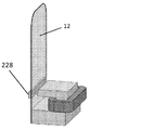
本明細書に記載のアクチュエータに対して多くの改変が行え得る。図2〜9、19および20に示すアクチュエータは引力のみを提供するが、追加のアクチュエータコンポーネントを加えることによって引力および斥力の両方(プッシュプル)の動作に変換され得る。例えば、図23に示すように別のアクチュエータを加えることによって、図2のカンチレバーファンをプッシュプル動作に変換できる。図2の電機子16とブレード12との間の引力を増すという改善の一つとして、図24に示すようにブレード12に裏当てプレート228を当てることがある。
Many modifications can be made to the actuators described herein. The actuators shown in FIGS. 2-9, 19 and 20 provide only attractive force, but can be converted to both attractive and repulsive (push-pull) operation by adding additional actuator components. For example, by adding another actuator as shown in FIG. 23, the cantilever fan in FIG. 2 can be converted into a push-pull operation. As one improvement in increasing the attractive force between the
ブレード駆動型またはクランプ駆動型態様はいずれも、幅広い種類の異なるアクチュエータを使用するように設計でき、具体的に選択される種類は典型的に具体的な用途の要件に基づく。 Either the blade-driven or clamp-driven aspects can be designed to use a wide variety of different actuators, with the specific selection typically being based on the specific application requirements.
本発明は、低い動作周波数での高い流量、および非常に長いファン寿命と共にカンチレバーファンの小型化を可能にするが、本発明の範囲は本明細書で提供する態様に決して限定されない。本発明の様々な態様および向上を本明細書に開示して、ブレード質量負荷、振動相殺および振動低減を介して向上したL/Wアスペクト比の安定性を維持しながら、カンチレバー作動、ブレードサイズの縮小に関する本発明の利点を説明しており、当業者はこれらの態様および向上の多くの異なる組合せを使用することを思い付くであろう。これらの態様の様々な組合せは全て所与の用途の要件によって決定され、および本発明の範囲内にあると考える。例えば、図25は、ブレード設計とブレード作動トポロジーとの多くの可能な組み合わせの一つを図示している。本発明の従属コンポーネントの具体的な組み合わせは、具体的な設計および最終製品の要件に応じた良好な設計実践によって決定される。 Although the present invention allows miniaturization of cantilever fans with high flow rates at low operating frequencies and very long fan lifetimes, the scope of the present invention is in no way limited to the embodiments provided herein. Various aspects and improvements of the present invention are disclosed herein to enable cantilever actuation, blade size, while maintaining improved L / W aspect ratio stability through blade mass loading, vibration cancellation and vibration reduction. Having described the advantages of the present invention with respect to reduction, those skilled in the art will come to use many different combinations of these aspects and enhancements. Various combinations of these aspects are all determined by the requirements of a given application and are considered to be within the scope of the present invention. For example, FIG. 25 illustrates one of many possible combinations of blade design and blade operating topology. The specific combination of the dependent components of the present invention is determined by good design practices depending on the specific design and end product requirements.
本発明の態様は、本発明の範囲内にあるあらゆる周波数において駆動され得る。所与のブレードの共振に等しいかまたは近い駆動周波数においてファンを動作することにより性能的利点が得られる一方で、本発明の範囲は駆動周波数とブレードの共振周波数との近さに限定されない。駆動周波数が、エネルギーが蓄えられる程ブレード共振に近い場合、ブレード変位振幅は蓄積エネルギーに比例して大きくなる。駆動周波数が瞬間的なブレード共振周波数に近ければ近いほど蓄積エネルギーは大きくなり、ブレード変位は大きくなり、気流は大きくなる。カンチレバーファンの動作は、蓄積エネルギーの有無に関わらず、本発明の範囲内にあると考慮される。 Aspects of the invention can be driven at any frequency that is within the scope of the invention. While operating performance is obtained by operating the fan at a drive frequency equal to or near the resonance of a given blade, the scope of the present invention is not limited to the proximity of the drive frequency and the blade resonance frequency. When the driving frequency is so close to the blade resonance that energy is stored, the blade displacement amplitude increases in proportion to the stored energy. The closer the drive frequency is to the instantaneous blade resonance frequency, the greater the stored energy, the greater the blade displacement, and the greater the airflow. The operation of the cantilever fan is considered to be within the scope of the present invention with or without stored energy.
ブレードは、金属、プラスチックまたはエラストマー等の多くの異なる材料から作られることができ、具体的な材料の選択は所与の用途の要件に基づくことが理解される。 It will be appreciated that the blade can be made from many different materials, such as metal, plastic or elastomer, and the specific material selection is based on the requirements of a given application.
カンチレバーファンに動力を与えるためには多くの異なる駆動回路が使用でき、これらは当業者には明らかである。これらの駆動回路は、ブレードがそれらの共振周波数またはその付近において動作し続けるためにPLLコントロール等の共振ロックコントロールを含み得る。 Many different drive circuits can be used to power the cantilever fan and will be apparent to those skilled in the art. These drive circuits may include a resonant lock control, such as a PLL control, to keep the blades operating at or near their resonant frequency.
本発明のファンの応用としては、熱管理用途において、マイクロプロセッサ等の電子部品、MODFETS、HBLEDおよび空気冷却を必要とするあらゆる電子機器コンポーネント等のパワー電子機器コンポーネント、ならびにヒートシンク、プリント基板カードおよび電子機器 筐体等の二次熱交換対象を含む広範囲の熱物体の熱交換のための空気移動が挙げられる。本発明のカンチレバーファンは、サーバ、PCタワー、ラップトップ、PDA等の製品プラットフォームに強制的に空気を通すため、または携帯電話、遠隔通信および軍事的用途等において密封された電子機器筐体内で空気を循環させるために使用され得る。 Applications of the fan of the present invention include electronic components such as microprocessors, power electronic components such as MODFETS, HBLED and any electronic components that require air cooling in heat management applications, and heat sinks, printed circuit board cards and electronics Air movement for heat exchange of a wide range of hot objects including secondary heat exchange objects such as equipment casings can be mentioned. The cantilever fan of the present invention is used to force air through product platforms such as servers, PC towers, laptops, PDAs, etc. or in sealed electronic equipment enclosures such as in mobile phones, telecommunications and military applications. Can be used to circulate.
その他の応用としては、一部の例を挙げると、化学反応させるためのガスおよび粒子物質の一般的な混合、流体計量、サンプル抽出、細菌兵器剤および一般的な化学分析のための空気サンプル抽出、粉砕もしくは凝集等の浮遊粒子における他の材料変化を作ること、またはこれらのプロセスのあらゆる組合せが挙げられる。 Other applications include general mixing of gases and particulate matter for chemical reactions, fluid metering, sample extraction, bacterial weapons and air sample extraction for general chemical analysis, to name a few , Making other material changes in suspended particles such as grinding or agglomeration, or any combination of these processes.
本発明のいくつかの態様の上記記載は、例示および説明の目的で提示してきた。提示の図面において、本明細書で提供した個別の態様の従属コンポーネントは、機能を明瞭にするために必ずしも互いに対して比例して描かれていない。実際の製品においては、個々のコンポーネントの相対的比は具体的な工学的設計要件によって決定される。本明細書で提供する態様は網羅的なものでも、開示した厳密な形態に本発明を限定するものでもなく、当然、上記教示を考慮して多くの改変および変更が可能である。本発明の原理およびその実用的応用を最も良く説明することで、想定される特定の使用に適するように当業者が様々な改変を加えて本発明を様々な態様において最も良好に利用できるように、態様を選択および説明した。上記記載は多くの詳述を含むが、これらは本発明の範囲を限定するものではなく、むしろそれらの代替的な態様の例示であると解釈されるべきである。 The foregoing descriptions of some aspects of the present invention have been presented for purposes of illustration and description. In the drawings presented, the dependent components of the individual aspects provided herein are not necessarily drawn to scale relative to each other for the sake of clarity. In actual products, the relative proportions of the individual components are determined by specific engineering design requirements. The embodiments provided herein are not intended to be exhaustive or to limit the invention to the precise forms disclosed, and, of course, many modifications and variations are possible in light of the above teachings. A best description of the principles of the invention and its practical application so that those skilled in the art may best utilize the invention in various aspects, with various modifications to suit the particular use envisioned. Aspects have been selected and described. While the above description includes many details, they should not be construed as limiting the scope of the invention, but rather as exemplifications of alternative embodiments thereof.
Claims (15)
ブレードがクランプ留めされた端部からブレード先端まで延びる長さを有する、
一方の端部でクランプ留めされ、かつ該クランプ留めされた端部からブレード上で最も離れた点に位置するブレード先端を含む、カンチレバーブレードと、
該ブレードの長さに沿った位置において該ブレードに周期的に力を加えて該ブレードの周期的なたわみを生じる、
該ブレードと共に振動しない少なくとも一つのコンポーネントを有し、かつ該ブレードのクランプ留めされた端部に対してほぼ不動である、アクチュエータと
を備えるカンチレバーファン。 The blade tip vibrates freely,
The blade has a length extending from the clamped end to the blade tip,
A cantilever blade including a blade tip clamped at one end and located at the furthest point on the blade from the clamped end;
Periodically applying a force to the blade at a position along the length of the blade to cause periodic deflection of the blade;
A cantilever fan comprising an actuator having at least one component that does not vibrate with the blade and substantially immovable relative to the clamped end of the blade.
をさらに備える、請求項1記載のカンチレバーファン。 2. The mass attached to the cantilever blade is further configured to improve blade vibration stability by reducing the occurrence of higher mechanical modes of the blade. Cantilever fans.
ファンの動作中、該脚部分は該パドル部分よりも曲がるように構成されている、
請求項1記載のカンチレバーファン。 The cantilever blade includes at least one leg portion and a paddle portion, the paddle portion being furthest from a clamped end of the blade, the leg portion connecting the paddle portion to the blade clamp;
The leg portion is configured to bend more than the paddle portion during operation of the fan.
The cantilever fan according to claim 1.
アクチュエータの周期的な力によって該クランプアセンブリが振動し、該クランプアセンブリの振動によってブレードに周期的な力が加わり、その結果カンチレバーブレードの周期的なたわみが生じる、
該クランプアセンブリに周期的な力を加える前記アクチュエータと
を備えるカンチレバーファン。 A cantilever blade clamped to the clamp assembly at one end;
The clamp assembly vibrates due to the periodic force of the actuator, and the vibration of the clamp assembly applies a periodic force to the blade, resulting in the cyclic deflection of the cantilever blade.
A cantilever fan comprising the actuator for applying a periodic force to the clamp assembly.
をさらに備える、請求項6記載のカンチレバーファン。 The cantilever fan of claim 6, further comprising a mass attached to the cantilever blade that provides improved stability of blade vibration by reducing the occurrence of higher mechanical modes of the blade.
ファンの動作中、該脚部分は該パドル部分よりも曲がるように構成されている、
請求項6記載のカンチレバーファン。 The cantilever blade includes at least one leg portion and a paddle portion, the paddle portion being furthest from a clamped end of the blade, the leg portion connecting the paddle portion to the blade clamp;
The leg portion is configured to bend more than the paddle portion during operation of the fan.
7. The cantilever fan according to claim 6.
ブレードの振動を励振するためのアクチュエータと、
を備えるカンチレバーファンであって、
該ブレードのより高次の機械的なモードが引き起こされることを低減すること、該ブレードの共振周波数を低減すること、および該ブレードのQ値を高めて、該ブレードを振動させるのに必要なエネルギーを低減することによってブレード振動の安定性を向上させるために、該クランプ留めされた端部から離れたブレードの一部分が該クランプ留めされた端部よりも高い質量含有率を有するような質量分布を該ブレードが有する、
前記カンチレバーファン。 A cantilever blade clamped by a clamp assembly at one end;
An actuator for exciting the vibration of the blade;
A cantilever fan comprising:
Energy required to reduce the occurrence of higher mechanical modes of the blade, reduce the resonance frequency of the blade, and increase the Q value of the blade to oscillate the blade To improve blade vibration stability by reducing the mass distribution such that a portion of the blade away from the clamped end has a higher mass content than the clamped end. The blade has,
The cantilever fan.
Applications Claiming Priority (3)
| Application Number | Priority Date | Filing Date | Title |
|---|---|---|---|
| US37685810P | 2010-08-25 | 2010-08-25 | |
| US61/376,858 | 2010-08-25 | ||
| PCT/US2011/048394 WO2012027215A2 (en) | 2010-08-25 | 2011-08-19 | Cantilever fan |
Publications (2)
| Publication Number | Publication Date |
|---|---|
| JP2013537600A true JP2013537600A (en) | 2013-10-03 |
| JP2013537600A5 JP2013537600A5 (en) | 2014-09-18 |
Family
ID=45723996
Family Applications (1)
| Application Number | Title | Priority Date | Filing Date |
|---|---|---|---|
| JP2013526039A Pending JP2013537600A (en) | 2010-08-25 | 2011-08-19 | Cantilever fan |
Country Status (6)
| Country | Link |
|---|---|
| US (2) | US9523367B2 (en) |
| EP (1) | EP2609338A4 (en) |
| JP (1) | JP2013537600A (en) |
| CN (1) | CN103140686A (en) |
| BR (1) | BR112013004270A8 (en) |
| WO (1) | WO2012027215A2 (en) |
Families Citing this family (18)
| Publication number | Priority date | Publication date | Assignee | Title |
|---|---|---|---|---|
| JP2013223818A (en) * | 2012-04-20 | 2013-10-31 | Murata Mfg Co Ltd | Piezoelectric actuator and electronic apparatus |
| CN103104526A (en) * | 2013-01-31 | 2013-05-15 | 新生源企业有限公司 | Structure of piezoelectric fan for heat dissipation and method thereof |
| CN105376989B (en) * | 2014-08-29 | 2018-06-01 | 台达电子工业股份有限公司 | Radiator |
| TWI583913B (en) * | 2014-08-29 | 2017-05-21 | 台達電子工業股份有限公司 | Heat dissipation device |
| TWI568344B (en) * | 2015-05-01 | 2017-01-21 | 蘇献欽 | Heat dissipating system |
| TWM529149U (en) * | 2016-04-15 | 2016-09-21 | Xian-Qin Su | Heat dissipation apparatus |
| CN107347242B (en) * | 2016-05-05 | 2019-08-20 | 华为技术有限公司 | A kind of radiator and communication equipment |
| EP3563431A4 (en) * | 2016-12-27 | 2020-07-29 | Perpetua, Inc. | High performance cantilever fan |
| US10943850B2 (en) | 2018-08-10 | 2021-03-09 | Frore Systems Inc. | Piezoelectric MEMS-based active cooling for heat dissipation in compute devices |
| US11464140B2 (en) | 2019-12-06 | 2022-10-04 | Frore Systems Inc. | Centrally anchored MEMS-based active cooling systems |
| WO2021086873A1 (en) | 2019-10-30 | 2021-05-06 | Frore System Inc. | Mems-based airflow system |
| CN115038879A (en) * | 2019-12-04 | 2022-09-09 | 波佩图阿有限公司 | Linear fan comprising a wire spring |
| US11796262B2 (en) | 2019-12-06 | 2023-10-24 | Frore Systems Inc. | Top chamber cavities for center-pinned actuators |
| US11510341B2 (en) * | 2019-12-06 | 2022-11-22 | Frore Systems Inc. | Engineered actuators usable in MEMs active cooling devices |
| KR20220146527A (en) * | 2020-03-04 | 2022-11-01 | 퍼페튜아 인코퍼레이티드 | Linear fan forced air cooling |
| US11765863B2 (en) | 2020-10-02 | 2023-09-19 | Frore Systems Inc. | Active heat sink |
| USD992996S1 (en) * | 2020-10-06 | 2023-07-25 | Harry Wong | Magnetic panel holder |
| CN112392780A (en) * | 2020-10-09 | 2021-02-23 | 杨杰 | Piezoelectric fan structure capable of blowing air to periphery and driving method |
Citations (4)
| Publication number | Priority date | Publication date | Assignee | Title |
|---|---|---|---|---|
| JPH01131898U (en) * | 1988-03-02 | 1989-09-07 | ||
| JPH0335298U (en) * | 1989-08-10 | 1991-04-05 | ||
| JP2005005896A (en) * | 2003-06-10 | 2005-01-06 | Seiko Epson Corp | Piezoelectric oscillating piece, method for manufacturing piezoelectric oscillating piece, piezoelectric oscillator and electronic equipment mounted with piezoelectric oscillator |
| JP2010029759A (en) * | 2008-07-28 | 2010-02-12 | Fujikura Ltd | Piezoelectric fan device |
Family Cites Families (45)
| Publication number | Priority date | Publication date | Assignee | Title |
|---|---|---|---|---|
| US4595338A (en) * | 1983-11-17 | 1986-06-17 | Piezo Electric Products, Inc. | Non-vibrational oscillating blade piezoelectric blower |
| JP2735198B2 (en) | 1987-11-16 | 1998-04-02 | カルソニック株式会社 | Aluminum heat exchanger |
| US5008582A (en) * | 1988-01-29 | 1991-04-16 | Kabushiki Kaisha Toshiba | Electronic device having a cooling element |
| JP2778128B2 (en) | 1989-06-30 | 1998-07-23 | 日本電気株式会社 | Method and apparatus for adaptive transform coding |
| US6123145A (en) | 1995-06-12 | 2000-09-26 | Georgia Tech Research Corporation | Synthetic jet actuators for cooling heated bodies and environments |
| US5758823A (en) | 1995-06-12 | 1998-06-02 | Georgia Tech Research Corporation | Synthetic jet actuator and applications thereof |
| US5966286A (en) | 1996-05-31 | 1999-10-12 | Intel Corporation | Cooling system for thin profile electronic and computer devices |
| US5861703A (en) | 1997-05-30 | 1999-01-19 | Motorola Inc. | Low-profile axial-flow single-blade piezoelectric fan |
| US6043978A (en) * | 1997-12-15 | 2000-03-28 | Eaton Corporation | Cooling device for circuit breakers |
| US6588497B1 (en) | 2002-04-19 | 2003-07-08 | Georgia Tech Research Corporation | System and method for thermal management by synthetic jet ejector channel cooling techniques |
| US7369115B2 (en) * | 2002-04-25 | 2008-05-06 | Immersion Corporation | Haptic devices having multiple operational modes including at least one resonant mode |
| JP2005133555A (en) * | 2003-10-28 | 2005-05-26 | Daikin Ind Ltd | Elastic vibrating plate fan |
| US7252140B2 (en) | 2004-09-03 | 2007-08-07 | Nuveatix, Inc. | Apparatus and method for enhanced heat transfer |
| KR100661647B1 (en) * | 2004-12-24 | 2006-12-26 | 삼성전자주식회사 | Ventilation apparatus |
| US7638928B2 (en) | 2005-06-30 | 2009-12-29 | Intel Corporation | Piezo actuator for cooling |
| US8069910B2 (en) | 2005-10-12 | 2011-12-06 | Nuventix, Inc. | Acoustic resonator for synthetic jet generation for thermal management |
| US7932535B2 (en) | 2005-11-02 | 2011-04-26 | Nuventix, Inc. | Synthetic jet cooling system for LED module |
| US7607470B2 (en) | 2005-11-14 | 2009-10-27 | Nuventix, Inc. | Synthetic jet heat pipe thermal management system |
| US7606029B2 (en) | 2005-11-14 | 2009-10-20 | Nuventix, Inc. | Thermal management system for distributed heat sources |
| US8430644B2 (en) | 2005-11-18 | 2013-04-30 | Nuventix, Inc. | Synthetic jet ejector for the thermal management of PCI cards |
| US8030886B2 (en) | 2005-12-21 | 2011-10-04 | Nuventix, Inc. | Thermal management of batteries using synthetic jets |
| WO2007100645A2 (en) | 2006-02-23 | 2007-09-07 | Nuventix, Inc. | Electronics package for synthetic jet ejectors |
| WO2007103384A2 (en) | 2006-03-07 | 2007-09-13 | Influent Corp. | Fluidic energy transfer devices |
| US8672648B2 (en) | 2006-05-23 | 2014-03-18 | Nuventix, Inc. | Methods for reducing the non-linear behavior of actuators used for synthetic jets |
| US8136576B2 (en) | 2006-06-22 | 2012-03-20 | Nuventix, Inc. | Vibration isolation system for synthetic jet devices |
| US8646701B2 (en) | 2006-07-05 | 2014-02-11 | Nuventix, Inc. | Moldable housing design for synthetic jet ejector |
| US8388142B2 (en) | 2006-10-13 | 2013-03-05 | Nuventix, Inc. | Thermal management of very small form factor projectors with synthetic jets |
| US7784972B2 (en) | 2006-12-22 | 2010-08-31 | Nuventix, Inc. | Thermal management system for LED array |
| US7642698B2 (en) * | 2007-03-30 | 2010-01-05 | Intel Corporation | Dual direction rake piezo actuator |
| US7538476B2 (en) * | 2007-03-30 | 2009-05-26 | Intel Corporation | Multi-layer piezoelectric actuators with conductive polymer electrodes |
| CN201037478Y (en) * | 2007-04-30 | 2008-03-19 | 力致科技股份有限公司 | Air current generator |
| US20080286133A1 (en) * | 2007-05-18 | 2008-11-20 | Forcecon Technology Co., Ltd. | Airflow generator |
| US7768779B2 (en) | 2007-06-04 | 2010-08-03 | Nuventix, Inc. | Synthetic jet ejector with viewing window and temporal aliasing |
| CN101372988A (en) | 2007-08-22 | 2009-02-25 | 英业达股份有限公司 | Swinging fan |
| CN101153617A (en) * | 2007-10-12 | 2008-04-02 | 苏州聚力电机有限公司 | Gas flow generator |
| US8066410B2 (en) | 2007-10-24 | 2011-11-29 | Nuventix, Inc. | Light fixture with multiple LEDs and synthetic jet thermal management system |
| US8845138B2 (en) | 2007-10-24 | 2014-09-30 | Nuventix, Inc. | Light fixture with multiple LEDs and synthetic jet thermal management system |
| US8290724B2 (en) | 2007-11-06 | 2012-10-16 | Nuventix, Inc. | Method and apparatus for controlling diaphragm displacement in synthetic jet actuators |
| US7619894B2 (en) * | 2008-02-22 | 2009-11-17 | Inventec Corporation | Heat dissipation device |
| WO2009119431A1 (en) | 2008-03-25 | 2009-10-01 | 株式会社村田製作所 | Piezoelectric fan apparatus and air-cooling apparatus using the same |
| US8579476B2 (en) | 2008-07-15 | 2013-11-12 | Nuventix, Inc. | Thermal management of led-based illumination devices with synthetic jet ejectors |
| US8299691B2 (en) | 2008-07-15 | 2012-10-30 | Nuventix, Inc. | Advanced synjet cooler design for LED light modules |
| US8777456B2 (en) | 2008-07-15 | 2014-07-15 | Nuventix, Inc. | Thermal management of LED-based illumination devices with synthetic jet ejectors |
| US7760499B1 (en) | 2009-05-14 | 2010-07-20 | Nuventix, Inc. | Thermal management system for card cages |
| DE112011100524T5 (en) | 2010-02-13 | 2012-11-29 | Nuventix, Inc. | Synthetic jet ejector and its structural design to promote mass production |
-
2011
- 2011-08-19 JP JP2013526039A patent/JP2013537600A/en active Pending
- 2011-08-19 WO PCT/US2011/048394 patent/WO2012027215A2/en active Application Filing
- 2011-08-19 BR BR112013004270A patent/BR112013004270A8/en not_active Application Discontinuation
- 2011-08-19 CN CN2011800479557A patent/CN103140686A/en active Pending
- 2011-08-19 US US13/818,513 patent/US9523367B2/en not_active Expired - Fee Related
- 2011-08-19 EP EP11820425.4A patent/EP2609338A4/en not_active Withdrawn
-
2016
- 2016-05-09 US US15/149,557 patent/US20160252105A1/en not_active Abandoned
Patent Citations (4)
| Publication number | Priority date | Publication date | Assignee | Title |
|---|---|---|---|---|
| JPH01131898U (en) * | 1988-03-02 | 1989-09-07 | ||
| JPH0335298U (en) * | 1989-08-10 | 1991-04-05 | ||
| JP2005005896A (en) * | 2003-06-10 | 2005-01-06 | Seiko Epson Corp | Piezoelectric oscillating piece, method for manufacturing piezoelectric oscillating piece, piezoelectric oscillator and electronic equipment mounted with piezoelectric oscillator |
| JP2010029759A (en) * | 2008-07-28 | 2010-02-12 | Fujikura Ltd | Piezoelectric fan device |
Also Published As
| Publication number | Publication date |
|---|---|
| WO2012027215A3 (en) | 2012-05-10 |
| EP2609338A4 (en) | 2017-02-15 |
| BR112013004270A2 (en) | 2016-08-02 |
| US9523367B2 (en) | 2016-12-20 |
| EP2609338A2 (en) | 2013-07-03 |
| WO2012027215A2 (en) | 2012-03-01 |
| US20160252105A1 (en) | 2016-09-01 |
| CN103140686A (en) | 2013-06-05 |
| BR112013004270A8 (en) | 2017-12-05 |
| US20130183154A1 (en) | 2013-07-18 |
Similar Documents
| Publication | Publication Date | Title |
|---|---|---|
| JP2013537600A (en) | Cantilever fan | |
| US8272851B2 (en) | Fluidic energy transfer devices | |
| JP5541827B2 (en) | Loudspeaker with balanced moment and torque | |
| Uchino et al. | Micro piezoelectric ultrasonic motors | |
| US20110220339A1 (en) | Method and apparatus for reducing acoustic noise in a synthetic jet | |
| KR102528102B1 (en) | High performance cantilever fan | |
| JP2009529119A5 (en) | ||
| Guo et al. | A small linear ultrasonic motor utilizing longitudinal and bending modes of a piezoelectric tube | |
| US20130230419A1 (en) | Force-equalization stationary-coil actuator for fluid movers | |
| US20190314860A1 (en) | Linear vibration motor | |
| JP2013523438A (en) | Tactile actuator system and method related thereto | |
| Shafik et al. | Piezoelectric motor technology: A review | |
| Friend et al. | A simple bidirectional linear microactuator for nanopositioning-the" Baltan" microactuator | |
| CN102868316A (en) | Paster-type dual-feet ultrasound motor oscillator | |
| TW201308865A (en) | Transducer module | |
| JP2010213537A (en) | Actuator and positioning device using it | |
| CN219181386U (en) | Vibration device and electronic apparatus | |
| Mohammed et al. | Research on a Linear Ultrasonic Motor with Double Cantilever Vibrators | |
| KR100602783B1 (en) | ultrasonic motor | |
| JP5281427B2 (en) | Oscillator | |
| JP2001352769A (en) | Method for manufacturing piezoelectric actuator and piezoelectric actuator | |
| Chau et al. | A short cylinder ultrasonic motor with novel excitation mode | |
| JP2007146730A (en) | Plate drive device, jet generating device and electronic apparatus | |
| JP2001218482A (en) | Vibration actuator | |
| JP2006203964A (en) | Magnetostrictive actuator |
Legal Events
| Date | Code | Title | Description |
|---|---|---|---|
| A711 | Notification of change in applicant |
Free format text: JAPANESE INTERMEDIATE CODE: A711 Effective date: 20131127 |
|
| A521 | Request for written amendment filed |
Free format text: JAPANESE INTERMEDIATE CODE: A821 Effective date: 20131127 |
|
| A521 | Request for written amendment filed |
Free format text: JAPANESE INTERMEDIATE CODE: A523 Effective date: 20140226 |
|
| A521 | Request for written amendment filed |
Free format text: JAPANESE INTERMEDIATE CODE: A523 Effective date: 20140729 |
|
| A621 | Written request for application examination |
Free format text: JAPANESE INTERMEDIATE CODE: A621 Effective date: 20140729 |
|
| RD04 | Notification of resignation of power of attorney |
Free format text: JAPANESE INTERMEDIATE CODE: A7424 Effective date: 20150514 |
|
| A131 | Notification of reasons for refusal |
Free format text: JAPANESE INTERMEDIATE CODE: A131 Effective date: 20150625 |
|
| A977 | Report on retrieval |
Free format text: JAPANESE INTERMEDIATE CODE: A971007 Effective date: 20150630 |
|
| A601 | Written request for extension of time |
Free format text: JAPANESE INTERMEDIATE CODE: A601 Effective date: 20150918 |
|
| A02 | Decision of refusal |
Free format text: JAPANESE INTERMEDIATE CODE: A02 Effective date: 20160302 |