JP2007285377A - Vibration damping device - Google Patents
Vibration damping device Download PDFInfo
- Publication number
- JP2007285377A JP2007285377A JP2006112112A JP2006112112A JP2007285377A JP 2007285377 A JP2007285377 A JP 2007285377A JP 2006112112 A JP2006112112 A JP 2006112112A JP 2006112112 A JP2006112112 A JP 2006112112A JP 2007285377 A JP2007285377 A JP 2007285377A
- Authority
- JP
- Japan
- Prior art keywords
- vibration
- damping device
- mover
- vibration damping
- active
- Prior art date
- Legal status (The legal status is an assumption and is not a legal conclusion. Google has not performed a legal analysis and makes no representation as to the accuracy of the status listed.)
- Granted
Links
Images


Abstract
Description
本発明は、自動車のエンジン等の振動発生源から発生する振動を減衰させる振動減衰装置に関する。 The present invention relates to a vibration damping device that attenuates vibrations generated from a vibration generation source such as an automobile engine.
例えば、自動車等の車内における静粛性・快適性を向上させるための一つの方策として、振動発生源であるエンジン等から発生する振動を減衰することが挙げられる。従来、振動を減衰するための装置として、車両のエンジンを支持する能動型防振装置であるアクチュエータ搭載エンジンマウントと、制御信号を生成する制御装置と、制御信号に基づいてアクチュエータを駆動する駆動装置とを備えたエンジン振動除去システムがあった(例えば、特許文献1を参照)。
上記特許文献1の振動減衰装置は、振動発生源となるエンジンで発生した振動とは逆位相の振動を、電磁アクチュエータを用いて加振するものである。また、この振動減衰装置は、エンジンの運転状態に応じた防振を行うことを目的としている。つまり、エンジンを備えた車両がアイドル運転状態であるときの低周波数の振動に対する防振と、車両が走行運転状態であるときの高周波の振動に対する防振を行うとき、制御信号に基づいて電磁アクチュエータを駆動制御し、異なる周波数の振動を発生させて防振を行っている。
For example, one measure for improving the quietness and comfort in a vehicle such as an automobile is to attenuate vibrations generated from an engine or the like that is a vibration generation source. 2. Description of the Related Art Conventionally, as an apparatus for damping vibration, an actuator-mounted engine mount that is an active vibration isolator that supports a vehicle engine, a control device that generates a control signal, and a drive device that drives the actuator based on the control signal (For example, refer to Patent Document 1).
The vibration attenuating device of
また、他の振動減衰装置として、バネ部材と、重りと、減衰部材とから構成される動吸振器があった(例えば、特許文献2を参照)。
上記特許文献2の動吸振器は、共通の支持部材から複数のバネ部材を延出し、当該複数のバネ部材の先端に重りを取り付けて揺動自在に片持ち支持し、さらに重りの揺動を減衰させるための減衰部材を取り付けている。この動吸振器は複数の動吸振器を備えたマルチ動吸振器として機能する。マルチ動吸振器は、バネ部材の長さを不等長としたり、各々のバネ部材における重りの位置を変更可能にすることで、バネ定数や固有振動数を各々の動吸振器において個別に設定し、複数の振動数に対して制振効果を得ようとするものである。
As another vibration damping device, there has been a dynamic vibration absorber composed of a spring member, a weight, and a damping member (see, for example, Patent Document 2).
The dynamic vibration absorber of
ところで、自動車のエンジン等の振動発生源は、常に一定の状態で駆動しているとは限らない。例えば、自動車の走行中にエンジンのスロットルバルブの開度を調節するとエンジン回転数が変動し、それに伴って発生する振動の周波数や強度が変化する。
このような振動発生源の振動状態が常に変動する環境において、特許文献1のエンジン振動除去システムでは、振動発生源から発生する振動に応じて逆位相の大きな振動を積極的に発生させる振動制御が行われる。
Incidentally, a vibration source such as an automobile engine is not always driven in a constant state. For example, when the opening of the throttle valve of the engine is adjusted while the automobile is running, the engine speed fluctuates, and the frequency and intensity of the vibrations generated accordingly change.
In such an environment where the vibration state of the vibration source is constantly fluctuating, the engine vibration removal system disclosed in
また、自動車のエンジン等はその性状、例えば、エンジンの種類、排気量、気筒数、形式、特性等により特有の固有振動が発生する場合や、振動周波数の領域が広範囲に亘る場合もある。
このような固有振動や領域の広い振動に対し、特許文献2の動吸振器では、例えば、バネ部材に設けた重りの取り付け位置を調整し、当該固有振動や領域の広い振動の減衰が図られる。
In addition, an automobile engine or the like may generate a specific natural vibration depending on the nature of the engine, for example, the type of engine, the displacement, the number of cylinders, the type, characteristics, or the like, or may have a wide vibration frequency range.
With respect to such a natural vibration or a vibration with a wide area, the dynamic vibration absorber of
ところが、特許文献1のエンジン振動除去システムでは、固有振動や振動領域が広範囲の振動を十分に減衰させようとすると、振動部材に大きい振動減衰能力を備えさせる必要がある。ところが、そのような振動減衰能力を付与するためには、例えば、アクチュエータの駆動能力を高くしたり、振動を発生させる部材の可動距離を長くしたり、電源装置を高出力タイプにしたりする等の必要が生じる。このため、装置構成が大型化・複雑化し、高いコストがかかってしまうことになる。
However, in the engine vibration removal system disclosed in
また、特許文献2の動吸振器は主に固有振動を減衰させるための装置であるが、基本的には振動発生源からの振動を能動的に検知するものであるため、減衰対象となる振動が小さい場合では、減衰効果が十分に発揮されないという問題がある。
さらに、減衰対象となる振動周波数が複数ある場合には、その数に応じたバネ部材や重りを設置したり、重りの選択および取り付け位置に関して複雑且つ微妙な調整が必要であったりする。このため、動吸振器の装置構成が複雑化・大型化し、コストアップを招くという問題もある。
The dynamic vibration absorber of
Furthermore, when there are a plurality of vibration frequencies to be damped, spring members and weights corresponding to the number of vibration frequencies may be installed, or complex and delicate adjustments regarding weight selection and attachment positions may be required. For this reason, there exists a problem that the apparatus structure of a dynamic vibration absorber is complicated and enlarged, and causes a cost increase.
本発明は、上記問題点に鑑みてなされたものであり、その目的とするところは、振動発生源から発生する振動の周波数が広範囲であっても、十分な振動減衰効果を得ることができる振動減衰装置を提供することにある。 The present invention has been made in view of the above-described problems, and an object of the present invention is to provide a vibration capable of obtaining a sufficient vibration damping effect even if the frequency of vibration generated from a vibration source is wide. It is to provide an attenuation device.
本発明に係る振動減衰装置の特徴構成は、振動発生源から発生する振動を減衰させる振動減衰装置であって、電磁アクチュエータにより振動周波数を制御しつつ、前記振動発生源から発生する振動とは逆の位相で第1可動子を共振させる能動振動部と、前記能動振動部を構成する非駆動部材に設けた第2可動子を、前記能動振動部が減衰させる振動領域とは異なる振動領域の振動によって共振させる受動振動部とを備えた点にある。 The characteristic configuration of the vibration attenuating device according to the present invention is a vibration attenuating device for attenuating the vibration generated from the vibration generating source, which is opposite to the vibration generated from the vibration generating source while controlling the vibration frequency by the electromagnetic actuator. Vibration in a vibration region different from the vibration region in which the active vibration unit attenuates the active vibration unit that resonates the first mover with a phase of the second movable member provided on the non-driving member constituting the active vibration unit. And a passive vibration part that resonates.
振動発生源から発生する振動には、種々の振動周波数・振動強度を有するものが含まれる。このような振動の振動領域は広範囲に亘るため、能動振動部だけで全ての領域の振動を減衰させようとすれば、振動減衰能力が大きい振動減衰装置を用いる必要がある。ところが、振動減衰能力の高い装置は大型化したり、装置構成が複雑化し、コストアップにもつながる。
そこで、本構成の振動減衰装置では、能動振動部に加えて受動振動部を備えている。両者は振動を減衰させる振動領域をそれぞれ分担するように機能する。例えば、能動振動部は振動発生源から発生する振動のうち振動状態の変動を伴う振動について減衰作用を発揮し、受動振動部はその振動発生源に特有の固有振動や一定レベル以上の高周波数の振動について減衰作用を発揮する。このため、能動振動部に過大な振動減衰能力を備えさせておく必要がなくなり、振動減衰装置の構成を大型化・複雑化しなくても十分な振動の減衰効果を得ることができる。
The vibration generated from the vibration source includes those having various vibration frequencies and vibration strengths. Since the vibration region of such vibrations covers a wide range, it is necessary to use a vibration damping device having a large vibration damping capability if it is intended to attenuate the vibrations of all regions using only the active vibration part. However, a device having a high vibration damping capability is increased in size, the device configuration is complicated, and the cost is increased.
Therefore, the vibration damping device of this configuration includes a passive vibration unit in addition to the active vibration unit. Both function so as to share a vibration region for damping the vibration. For example, the active vibration part exhibits a damping action for vibrations that occur from the vibration source and that accompany changes in the vibration state, and the passive vibration part has natural vibrations specific to the vibration source and high frequencies above a certain level. Demonstrates damping action for vibration. For this reason, it is not necessary to provide the active vibration part with an excessive vibration damping capability, and a sufficient vibration damping effect can be obtained without increasing the size and complexity of the vibration damping device.
本発明の振動減衰装置において、前記非駆動部材を、前記第1可動子の振動をガイドするガイド部材とすることも可能である。 In the vibration damping device of the present invention, the non-driving member may be a guide member that guides the vibration of the first mover.
本構成の振動減衰装置では、非駆動部材を第1可動子の振動をガイドするガイド部材としているため、能動振動部の一部と受動振動部の一部とを共有化することができる。このため、振動減衰装置の構成を簡略化することができ、それによってコンパクト化を達成することができる。 In the vibration damping device of this configuration, since the non-driving member is a guide member that guides the vibration of the first mover, a part of the active vibration part and a part of the passive vibration part can be shared. For this reason, the configuration of the vibration damping device can be simplified, thereby achieving compactness.
本発明の振動減衰装置において、前記ガイド部材を、前記第1可動子を貫通する少なくとも一本の長尺状部材とすることも可能である。 In the vibration damping device of the present invention, the guide member may be at least one long member that penetrates the first mover.
本構成の振動減衰装置では、ガイド部材である少なくとも一本の長尺状部材が第1可動子を貫通していることから、長尺状部材が第1可動子の振動方向における投影領域の外方に延出する可能性が小さい。このため、振動減衰装置をさらにコンパクト化することができる。また、長尺状部材の長手方向に沿って能動振動部と受動振動部とを配置することができるので、振動減衰装置の構成を簡単にすることができる。 In the vibration damping device of this configuration, since at least one elongate member that is a guide member passes through the first mover, the elongate member is outside the projection region in the vibration direction of the first mover. The possibility of extending toward is small. For this reason, the vibration damping device can be further downsized. Moreover, since the active vibration part and the passive vibration part can be arranged along the longitudinal direction of the long member, the configuration of the vibration damping device can be simplified.
本発明の振動減衰装置において、前記長尺状部材を、前記第1可動子の中央を貫通する単一の部材とすることも可能ある。 In the vibration damping device of the present invention, the elongated member may be a single member that passes through the center of the first mover.
本構成の振動減衰装置では、長尺状部材が第1可動子の中央を貫通しているので、能動振動部の中央位置に受動振動部が集められ、第1可動子の端部の拡がりが小さくなる。このため、振動減衰装置をより一層コンパクト化することができる。さらに、長尺状部材を単一の部材とすることで、第2可動子の長尺部材への取り付け部分を一箇所にまとめることができる、このため、第2可動子が複数ある場合、取り付けの手間を削減することができる。 In the vibration damping device of this configuration, since the long member passes through the center of the first movable element, the passive vibration part is collected at the center position of the active vibration part, and the end of the first movable element is spread. Get smaller. For this reason, the vibration damping device can be made more compact. Further, by making the long member a single member, the attachment part of the second movable element to the long member can be gathered in one place. For this reason, when there are multiple second movable elements, Can be saved.
以下、本発明の実施形態を図面に基づいて説明する。ただし、本発明はこれらの実施形態に限定されることを意図するものではなく、当業者が実施可能な範囲において、種々の改変や変更等が可能である。 Hereinafter, embodiments of the present invention will be described with reference to the drawings. However, the present invention is not intended to be limited to these embodiments, and various modifications and changes are possible within the scope that can be implemented by those skilled in the art.
(第1実施形態)
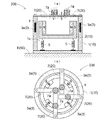
図1は、本発明の第1実施形態による振動減衰装置100の概略構成図である。(a)は振動減衰装置100の断面図であり、(b)は振動減衰装置100の上面図である。
振動減衰装置100は、振動発生源50の一例であるエンジンEに取り付けて使用される。振動減衰装置100は、能動振動部10と受動振動部20とを備えている。
(First embodiment)
FIG. 1 is a schematic configuration diagram of a
The
能動振動部10は、エンジンEに取り付けられる非駆動部材である有底円筒空間部1aを有する固定子1と、当該有底円筒空間部1aを取り囲む壁部を内側および外側から挟み込む姿勢を維持して円筒軸心方向に移動(振動)することが可能な駆動部材である第1可動子2とを有している。固定子1には第1可動子2の振動周波数を制御するための電磁アクチュエータ3が設けられている。
本実施形態では、電磁アクチュエータ3としてコイル3aが固定子1の有底円筒空間部1aを取り囲む壁部内に設けられている。同時に、第1可動子2におけるコイル3aと対向する位置には永久磁石4が設けられている。第1可動子2は、固定子1に対して非接触状態を維持しながら、固定子1に対して相対移動(振動)が可能となっている。
The
In the present embodiment, a
図示しない電源手段からエンジンEの駆動状態に応じた電流がコイル3aに印加されると、電磁誘導によりコイル3aから第1可動子2の永久磁石4に向けて磁界が発生し、第1可動子2に対して引力または斥力を及ぼすことができる。
第1可動子2は、エンジンEに対してバネ等の弾性部材5で連結されているので、自然状態でもエンジンEからの振動と反対方向に振動することにより、ある程度エンジンEの振動を減衰させることができる。しかし、上述のようにコイル3aからの磁界により、第1可動子2に対して引力または斥力を付与することで、能動振動部10の振動周波数を積極的に調節することが可能となる。これにより、振動減衰効果が増幅される。特に、エンジンEの回転数等に基づいて、図示しないエンジンECU等がコイル3aの印加電流を適宜調整制御し、エンジンEから発生する振動とは逆の位相で第1可動子2が共振状態を形成する振動周波数に合わせることで、エンジンEの振動を大きく減衰させることができる。
When a current according to the driving state of the engine E is applied to the
Since the
エンジンEから発生する振動には、種々の振動周波数および振動強度を有する振動が含まれている。図2は、あるエンジンEについて、回転数、すなわち振動周波数を変動させたときに発生する振動強度を模式的に表したグラフである。 The vibration generated from the engine E includes vibrations having various vibration frequencies and vibration strengths. FIG. 2 is a graph schematically showing the vibration intensity generated when the rotational speed, that is, the vibration frequency is changed for a certain engine E.
エンジンEの振動周波数を低周波数から高周波数に変化させると、図示するように、特定の振動周波数に達したときに強度の大きな振動が発生する。この強度の大きな振動は、エンジンEの性状、例えば、エンジンE種類、排気量、気筒数、形式、特性等による固有の振動(本明細書では固有振動と呼ぶ)である。
また、エンジンEの振動周波数をさらに高周波数に変化させると、上記能動振動部10だけでは十分に減衰できない領域にも振動(本明細書では高周波振動と呼ぶ)が存在する。
When the vibration frequency of the engine E is changed from a low frequency to a high frequency, as shown in the drawing, a vibration having a high strength is generated when a specific vibration frequency is reached. This high-intensity vibration is a characteristic vibration (referred to as a natural vibration in this specification) due to the nature of the engine E, for example, the type of engine E, the displacement, the number of cylinders, the type, and characteristics.
Further, when the vibration frequency of the engine E is changed to a higher frequency, vibration (referred to as high frequency vibration in this specification) also exists in a region that cannot be sufficiently damped by the
図2に例示する振動領域の略全てに対して振動減衰効果が得られるように、高い振動減衰能力を有する装置を設計することも可能である。しかし、振動減衰装置の能力を過剰に高めると、装置が大型化・複雑化し、コストアップを招くことになる。そう考えると、能動振動部のみを有する振動減衰装置で種々の振動を処理することには一定の限界があり、例えば、図2において、振動周波数がF1より高い領域や振動強度がI1より大きい領域についてまで振動減衰効果を得ることは困難である。 It is also possible to design a device having a high vibration damping capability so that a vibration damping effect can be obtained for substantially all of the vibration regions illustrated in FIG. However, if the capacity of the vibration damping device is excessively increased, the device becomes larger and more complicated, resulting in an increase in cost. Considering this, there is a certain limit to processing various vibrations with the vibration damping device having only the active vibration part. For example, in FIG. 2, the region where the vibration frequency is higher than F1 or the region where the vibration intensity is larger than I1. It is difficult to obtain a vibration damping effect.
そこで、このような振動強度の大きい固有振動や高周波数振動を減衰させるためには、そのような固有振動や高周波数振動に対して有効に作用する補助的な振動減衰機構を使用することが効果的である。すなわち、上記振動減衰機構が、能動振動部10によって減衰可能な振動領域とは異なる振動領域の振動によって共振するものであれば、全振動領域について振動を低減させることが可能となる。
Therefore, in order to attenuate such natural vibration and high frequency vibration with large vibration intensity, it is effective to use an auxiliary vibration damping mechanism that effectively acts on such natural vibration and high frequency vibration. Is. That is, if the vibration damping mechanism resonates due to vibrations in a vibration region different from the vibration region that can be attenuated by the
このような振動減衰機構として、本発明の振動減衰装置100では、受動振動部20を設ける。能動振動部10に加えて受動心動部20を備える本発明の振動減衰装置100では、振動を減衰させる振動領域を、能動振動部10および受動心動部20がそれぞれ分担するように機能する。具体的には、能動振動部10はエンジンEから発生する振動のうち振動状態の変動を伴う振動について減衰作用を発揮し、受動振動部20はそのエンジンEに特有の固有振動や一定レベル以上の高周波数の振動について減衰作用を発揮する。このため、能動振動部10に過大な振動減衰能力を備えさせておく必要がなくなり、振動減衰装置100の構成を大型化・複雑化しなくても十分な振動の減衰効果を得ることができる。受動振動部20の具体的構成については次に説明する。
As such a vibration damping mechanism, the
受動振動部20は、能動振動部10を構成する固定子1に設けた第2可動子7を有する。例えば、固定子1の有底円筒空間部1aの底部中央から一本の長尺状部材1bを延出させ、第1可動子2の中央部を貫通させる。長尺状部材1bおよび第1可動子2の貫通孔2aは、第1可動子2が長尺状部材1bに対してストレスなく相対移動(振動)できるような形状およびサイズに構成されている。このため、固定子1の長尺状部材1bは、第1可動子2の振動をガイドするガイド部材として機能することができ、能動振動部10の振動動作を安定させ且つスムーズにすることができる。
The
第2可動子7は、貫通孔2aから突出する長尺状部材1bの先端部に取り付けられている。第2可動子7は、例えば、プレート状部材であり、その両端に固有振動と逆位相の共振状態を形成するためのウェイト7aが取り付けられている。第2可動子7に固定子1の長尺状部材1bを介してエンジンEの固有振動または高周波振動が伝達されると、第2可動子7を構成するプレート状部材が適切に撓み振動することにより、当該固有振動または高周波振動とは逆位相で共振をする。その結果、エンジンEの固有振動または高周波振動が減衰される。
The 2nd needle |
第2可動子7のウェイト7aの質量を変更したり、プレート状部材への取り付け位置を調整すれば、異なる振動周波数を有する固有振動や高周波数振動に対応した共振状態を形成することができる。
If the mass of the
第2可動子7は、第1可動子1に対して非接触状態にあるので、第1可動子1と第2可動子7とが互いの振動によって干渉されることはない。従って、第1可動子1および第2可動子7は独立してそれぞれの共振状態を形成し、各自が担当する振動領域において振動減衰効果を発揮することができる。
Since the 2nd needle |
第2可動子7を上記のような構成とすることによって次のような利点がある。
先ず、受動振動部20の一部が能動振動部10の固定子1の一部と共有することになるので、振動減衰装置100の構成を簡略化することができ、コンパクト化することができる。
The following advantages are obtained by configuring the second
First, since a part of the
また、長尺状部材1bが第1可動子2の振動方向における投影領域から外方に延出する可能性が小さくなるため、長尺状部材1bの長手方向に沿って能動振動部10と受動振動部20とを配置することができる。このため、振動減衰装置100をさらにコンパクト化することができる。
Further, since the possibility that the long member 1b extends outward from the projection region in the vibration direction of the
また、図1のように、長尺状部材1bが第1可動子2の中央を貫通するように構成すれば、能動振動部10の中央位置に受動振動部20が集められ、第1可動子2の端部の拡がりが小さくなるので、より一層コンパクト化することができる。
Further, as shown in FIG. 1, if the elongated member 1 b is configured to penetrate the center of the first
さらに、図1のように、長尺状部材1bを単一の部材とすれば、第2可動子7の長尺部材1bへの取り付け部分を一箇所にまとめることができので、第2可動子7が複数ある場合、取り付けの手間を削減することができる。
Further, as shown in FIG. 1, if the long member 1b is a single member, the
(第2実施形態)
図3は、本発明の第2実施形態による振動減衰装置200の概略構成図である。(a)は振動減衰装置200の断面図であり、(b)は振動減衰装置200の上面図である。
振動減衰装置200は、前記第1実施形態の振動減衰装置100と比較して、能動振動部10および受動振動部20の形状、位置関係が異なっているが、同じ参照符号を付した各部材の機能は振動減衰装置100と同様である。
(Second Embodiment)
FIG. 3 is a schematic configuration diagram of a
The
能動振動部10は、エンジンEに取り付けられる非駆動部材である円筒中空部1cを有する固定子1と、当該円筒中空部1cに収まる姿勢を維持して円筒軸心方向に移動(振動)することが可能な有底円筒状の駆動部材である第1可動子2とを有している。固定子1の円筒中空部1aを取り囲む壁部には第1可動子2の振動周波数を制御するための電磁アクチュエータ3としてのコイル3aが設けられている。同時に、第1可動子2におけるコイル3aと対向する位置には永久磁石4が設けられている。第1可動子2は、固定子1に対して非接触状態を維持しながら、固定子1に対して相対移動(振動)が可能となっている。固定子1は、第1可動子2が円筒軸心方向に移動可能なように、第1可動子2の外側を包囲しており、第1可動子2の振動をガイドするガイド部材としても機能する。
The
第1可動子2は、前記第1実施形態と同様に、エンジンEに対してバネ等の弾性部材5で連結されているので、自然状態でもエンジンEからの振動と反対方向に振動することにより、ある程度エンジンEの振動を吸収することができるが、コイル3aから第1可動子2に引力または斥力が付与されることにより、能動振動部10の振動周波数を積極的に調節することが可能となる。これにより、振動減衰効果が増幅される。
Since the
受動振動部20を構成する第2可動子7は、振動減衰装置200のコンパクト化を達成するべく、固定子1の円筒中空部1aを取り囲む壁部の上縁側に円筒内方に向けて設けられている。第2可動子7を構成するプレート状部材は、その撓み部分の長さができるだけ長くなるように、図3(b)のごとく、円筒中空部1aの中心からやや偏心させた方向に向けられている。
The second
本実施形態では、第2可動子7は固定子1に四箇所設けられており、各第2可動子7のプレート状部材には、それぞれ異なる位置にウェイト7aが取り付けられている。従って、本実施形態の振動減衰装置200では、四種類までの固有振動数を有する固有振動に対して減衰効果を発揮することができる。
振動数が四種類よりも多い場合は、第2可動子7の設置個数を増加したり、ウェイト7aの位置を異ならせることで、すべての固有振動に対して減衰効果を発揮することができる。
In the present embodiment, the second
When the number of vibrations is greater than four, the damping effect can be exerted on all natural vibrations by increasing the number of the second
本発明の振動減衰装置は、上記実施形態で説明したような自動車用エンジンの振動減衰装置以外にも種々の分野において適用することができる。例えば、住宅用制振装置、精密機器用制振装置等においても、本発明の振動減衰装置は有効に利用することができる。 The vibration damping device of the present invention can be applied in various fields other than the vibration damping device for an automobile engine as described in the above embodiment. For example, the vibration damping device of the present invention can also be used effectively in residential vibration control devices, precision device vibration control devices, and the like.
1 固定子
2 第1可動子
3 電磁アクチュエータ
5 ガイド部材
7 第2可動子
10 能動振動部
20 受動振動部
50 振動発生源
100 振動減衰装置
DESCRIPTION OF
Claims (4)
電磁アクチュエータにより振動周波数を制御しつつ、前記振動発生源から発生する振動とは逆の位相で第1可動子を共振させる能動振動部と、
前記能動振動部を構成する非駆動部材に設けた第2可動子を、前記能動振動部が減衰させる振動領域とは異なる振動領域の振動によって共振させる受動振動部とを備えた振動減衰装置。 A vibration damping device that attenuates vibration generated from a vibration source,
An active vibration unit that resonates the first mover with a phase opposite to the vibration generated from the vibration source while controlling the vibration frequency by an electromagnetic actuator;
A vibration damping apparatus comprising: a passive vibration unit that resonates a second movable element provided on a non-driving member constituting the active vibration unit by vibration in a vibration region different from a vibration region attenuated by the active vibration unit.
Priority Applications (1)
| Application Number | Priority Date | Filing Date | Title |
|---|---|---|---|
| JP2006112112A JP4626820B2 (en) | 2006-04-14 | 2006-04-14 | Vibration damping device |
Applications Claiming Priority (1)
| Application Number | Priority Date | Filing Date | Title |
|---|---|---|---|
| JP2006112112A JP4626820B2 (en) | 2006-04-14 | 2006-04-14 | Vibration damping device |
Publications (2)
| Publication Number | Publication Date |
|---|---|
| JP2007285377A true JP2007285377A (en) | 2007-11-01 |
| JP4626820B2 JP4626820B2 (en) | 2011-02-09 |
Family
ID=38757358
Family Applications (1)
| Application Number | Title | Priority Date | Filing Date |
|---|---|---|---|
| JP2006112112A Expired - Fee Related JP4626820B2 (en) | 2006-04-14 | 2006-04-14 | Vibration damping device |
Country Status (1)
| Country | Link |
|---|---|
| JP (1) | JP4626820B2 (en) |
Cited By (3)
| Publication number | Priority date | Publication date | Assignee | Title |
|---|---|---|---|---|
| JP2009168099A (en) * | 2008-01-15 | 2009-07-30 | Hitachi Plant Technologies Ltd | Damper structure |
| CN110520608A (en) * | 2017-11-24 | 2019-11-29 | 三菱重工发动机和增压器株式会社 | The vibration suppressing method and booster of booster |
| EP3648469A1 (en) * | 2018-10-31 | 2020-05-06 | Yamaha Corporation | Microphone |
Citations (6)
| Publication number | Priority date | Publication date | Assignee | Title |
|---|---|---|---|---|
| JPH1073143A (en) * | 1996-08-30 | 1998-03-17 | Osamu Nishihara | Hybrid damper |
| JP2001132793A (en) * | 1999-11-05 | 2001-05-18 | Tokai Rubber Ind Ltd | Active-type dynamic vibration damper for building structure |
| JP2001173714A (en) * | 1999-12-20 | 2001-06-26 | Tokai Rubber Ind Ltd | Active damper |
| JP2001182775A (en) * | 1999-12-27 | 2001-07-06 | Bridgestone Corp | Vibration insulating device |
| JP2004257564A (en) * | 2004-04-05 | 2004-09-16 | Kazuto Sedo | Dynamic vibration absorber |
| JP2005299832A (en) * | 2004-04-13 | 2005-10-27 | Tokai Rubber Ind Ltd | Driving method for active vibration control device |
-
2006
- 2006-04-14 JP JP2006112112A patent/JP4626820B2/en not_active Expired - Fee Related
Patent Citations (6)
| Publication number | Priority date | Publication date | Assignee | Title |
|---|---|---|---|---|
| JPH1073143A (en) * | 1996-08-30 | 1998-03-17 | Osamu Nishihara | Hybrid damper |
| JP2001132793A (en) * | 1999-11-05 | 2001-05-18 | Tokai Rubber Ind Ltd | Active-type dynamic vibration damper for building structure |
| JP2001173714A (en) * | 1999-12-20 | 2001-06-26 | Tokai Rubber Ind Ltd | Active damper |
| JP2001182775A (en) * | 1999-12-27 | 2001-07-06 | Bridgestone Corp | Vibration insulating device |
| JP2004257564A (en) * | 2004-04-05 | 2004-09-16 | Kazuto Sedo | Dynamic vibration absorber |
| JP2005299832A (en) * | 2004-04-13 | 2005-10-27 | Tokai Rubber Ind Ltd | Driving method for active vibration control device |
Cited By (5)
| Publication number | Priority date | Publication date | Assignee | Title |
|---|---|---|---|---|
| JP2009168099A (en) * | 2008-01-15 | 2009-07-30 | Hitachi Plant Technologies Ltd | Damper structure |
| CN110520608A (en) * | 2017-11-24 | 2019-11-29 | 三菱重工发动机和增压器株式会社 | The vibration suppressing method and booster of booster |
| US11131325B2 (en) | 2017-11-24 | 2021-09-28 | Mitsubishi Heavy Industries Engine & Turbocharger, Ltd. | Vibration suppressing method for supercharger, and supercharger |
| CN110520608B (en) * | 2017-11-24 | 2021-10-26 | 三菱重工发动机和增压器株式会社 | Vibration suppression method for supercharger and supercharger |
| EP3648469A1 (en) * | 2018-10-31 | 2020-05-06 | Yamaha Corporation | Microphone |
Also Published As
| Publication number | Publication date |
|---|---|
| JP4626820B2 (en) | 2011-02-09 |
Similar Documents
| Publication | Publication Date | Title |
|---|---|---|
| JP5338951B2 (en) | Vibration control device | |
| US8662266B2 (en) | Electromotive active dynamic vibration absorber apparatus for vehicle | |
| JPH1038020A (en) | Vibration damping device | |
| JP4626820B2 (en) | Vibration damping device | |
| JP5547000B2 (en) | Engine mounting system | |
| JP2003028232A (en) | Device for suppressing vibration in driven system | |
| JP3398634B2 (en) | Active vibration suppression device | |
| KR100802547B1 (en) | Hybrid mount | |
| JP2009226967A (en) | Engine vibration damping system | |
| JP2006077982A (en) | Active vibration reducer | |
| JP2009236225A (en) | Dynamic damper device | |
| KR101448733B1 (en) | Active Dynamic Vibration Absorber | |
| JPH11287284A (en) | Vibration isolating device | |
| JP2010261490A (en) | Vibration damping device | |
| KR101619179B1 (en) | Active dynamic vibration absorber | |
| KR100901088B1 (en) | Generating device and vibrating generation assembly | |
| JPH07119790A (en) | Vibration absorbing device | |
| JPH10159891A (en) | Vibration proof device |
Legal Events
| Date | Code | Title | Description |
|---|---|---|---|
| A621 | Written request for application examination |
Free format text: JAPANESE INTERMEDIATE CODE: A621 Effective date: 20090325 |
|
| A977 | Report on retrieval |
Free format text: JAPANESE INTERMEDIATE CODE: A971007 Effective date: 20101007 |
|
| TRDD | Decision of grant or rejection written | ||
| A01 | Written decision to grant a patent or to grant a registration (utility model) |
Free format text: JAPANESE INTERMEDIATE CODE: A01 Effective date: 20101014 |
|
| A01 | Written decision to grant a patent or to grant a registration (utility model) |
Free format text: JAPANESE INTERMEDIATE CODE: A01 |
|
| A61 | First payment of annual fees (during grant procedure) |
Free format text: JAPANESE INTERMEDIATE CODE: A61 Effective date: 20101027 |
|
| FPAY | Renewal fee payment (event date is renewal date of database) |
Free format text: PAYMENT UNTIL: 20131119 Year of fee payment: 3 |
|
| FPAY | Renewal fee payment (event date is renewal date of database) |
Free format text: PAYMENT UNTIL: 20131119 Year of fee payment: 3 |
|
| LAPS | Cancellation because of no payment of annual fees |