JP4820133B2 - 発光装置 - Google Patents
発光装置 Download PDFInfo
- Publication number
- JP4820133B2 JP4820133B2 JP2005262964A JP2005262964A JP4820133B2 JP 4820133 B2 JP4820133 B2 JP 4820133B2 JP 2005262964 A JP2005262964 A JP 2005262964A JP 2005262964 A JP2005262964 A JP 2005262964A JP 4820133 B2 JP4820133 B2 JP 4820133B2
- Authority
- JP
- Japan
- Prior art keywords
- led chip
- light
- lens
- light emitting
- color conversion
- Prior art date
- Legal status (The legal status is an assumption and is not a legal conclusion. Google has not performed a legal analysis and makes no representation as to the accuracy of the status listed.)
- Expired - Lifetime
Links
Images


Classifications
-
- H—ELECTRICITY
- H10—SEMICONDUCTOR DEVICES; ELECTRIC SOLID-STATE DEVICES NOT OTHERWISE PROVIDED FOR
- H10H—INORGANIC LIGHT-EMITTING SEMICONDUCTOR DEVICES HAVING POTENTIAL BARRIERS
- H10H20/00—Individual inorganic light-emitting semiconductor devices having potential barriers, e.g. light-emitting diodes [LED]
- H10H20/80—Constructional details
- H10H20/85—Packages
- H10H20/851—Wavelength conversion means
- H10H20/8515—Wavelength conversion means not being in contact with the bodies
Landscapes
- Led Device Packages (AREA)
- Led Devices (AREA)
Description
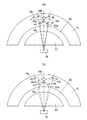
11 導電性基板
12 発光部
14 ボンディングワイヤ
20 実装基板
21 金属板
22 絶縁層
23 導体パターン
30 サブマウント部材
40 リフレクタ
50 封止部
60 レンズ
60a 光入射面
60b 光出射面
70 色変換部材
70a 内面
70b 外面
80 空気層
Claims (1)
- LEDチップと、LEDチップが実装されたベース部材と、ベース部材におけるLEDチップの実装面側でLEDチップを囲みLEDチップから放射された光を反射する枠状のリフレクタであって前記実装面から離れるにつれて開口面積が徐々に大きくなる形状に形成されたリフレクタと、リフレクタの内側に充填されLEDチップを封止した封止樹脂からなる封止部と、封止部側の光入射面が平面状に形成されるとともに光出射面が凸曲面状に形成され封止部およびリフレクタに重ねて配置されたレンズと、LEDチップから放射された光によって励起されてLEDチップの発光色とは異なる色の光を放射する蛍光体を透明材料とともに成形した成形品であってレンズの前記光出射面側にレンズを覆い前記光出射面との間に空気層が形成される形で配設されるドーム状の色変換部材とを備えてなり、レンズとリフレクタとは互いの光軸が一致し且つ各光軸がLEDチップを通るように配置され、レンズは、前記封止樹脂の屈折率以上の屈折率を有する材料により形成され、且つ、前記光出射面が、前記光入射面から入射した光を前記光出射面と空気層との境界で全反射させない凸曲面状であり球面の一部により形成されており、当該球面の中心がLEDチップの厚み方向に沿った発光部の中心線上に位置するように配置されてなり、色変換部材は、内面が前記光出射面に沿った形状であり前記光出射面に対応した前記球面よりも直径が大きな球面の一部からなる形状に形成されており、レンズの前記光出射面と色変換部材の内面との間の距離が略一定値となっており、色変換部材は、位置によらず法線方向に沿った肉厚が一様となるように成形されてなることを特徴とする発光装置。
Priority Applications (1)
| Application Number | Priority Date | Filing Date | Title |
|---|---|---|---|
| JP2005262964A JP4820133B2 (ja) | 2005-07-25 | 2005-09-09 | 発光装置 |
Applications Claiming Priority (3)
| Application Number | Priority Date | Filing Date | Title |
|---|---|---|---|
| JP2005214979 | 2005-07-25 | ||
| JP2005214979 | 2005-07-25 | ||
| JP2005262964A JP4820133B2 (ja) | 2005-07-25 | 2005-09-09 | 発光装置 |
Related Child Applications (1)
| Application Number | Title | Priority Date | Filing Date |
|---|---|---|---|
| JP2008019555A Division JP4925346B2 (ja) | 2005-07-25 | 2008-01-30 | 発光装置 |
Publications (2)
| Publication Number | Publication Date |
|---|---|
| JP2007059852A JP2007059852A (ja) | 2007-03-08 |
| JP4820133B2 true JP4820133B2 (ja) | 2011-11-24 |
Family
ID=37923031
Family Applications (1)
| Application Number | Title | Priority Date | Filing Date |
|---|---|---|---|
| JP2005262964A Expired - Lifetime JP4820133B2 (ja) | 2005-07-25 | 2005-09-09 | 発光装置 |
Country Status (1)
| Country | Link |
|---|---|
| JP (1) | JP4820133B2 (ja) |
Families Citing this family (4)
| Publication number | Priority date | Publication date | Assignee | Title |
|---|---|---|---|---|
| JP2008235827A (ja) * | 2007-03-23 | 2008-10-02 | Matsushita Electric Works Ltd | 発光装置 |
| JP2007214592A (ja) * | 2007-04-26 | 2007-08-23 | Kyocera Corp | 発光装置 |
| KR101068867B1 (ko) * | 2009-05-28 | 2011-09-30 | 삼성엘이디 주식회사 | 발광 다이오드 패키지 |
| JP2015060995A (ja) | 2013-09-19 | 2015-03-30 | 株式会社東芝 | 発光装置 |
Family Cites Families (8)
| Publication number | Priority date | Publication date | Assignee | Title |
|---|---|---|---|---|
| JP4306846B2 (ja) * | 1998-11-20 | 2009-08-05 | 株式会社朝日ラバー | 照明装置 |
| JP4680334B2 (ja) * | 1999-01-13 | 2011-05-11 | 株式会社朝日ラバー | 発光装置 |
| JP4269709B2 (ja) * | 2002-02-19 | 2009-05-27 | 日亜化学工業株式会社 | 発光装置およびその製造方法 |
| JP4421192B2 (ja) * | 2003-02-10 | 2010-02-24 | スタンレー電気株式会社 | 発光ダイオード用封止樹脂組成物及びそれを用いた表面実装型発光ダイオード |
| JP4385741B2 (ja) * | 2003-11-25 | 2009-12-16 | パナソニック電工株式会社 | 発光装置 |
| JP3921200B2 (ja) * | 2003-12-19 | 2007-05-30 | 京セラ株式会社 | 発光装置 |
| JP4146406B2 (ja) * | 2004-08-31 | 2008-09-10 | シャープ株式会社 | 発光素子および発光素子の製造方法 |
| JP4432724B2 (ja) * | 2004-10-22 | 2010-03-17 | パナソニック電工株式会社 | 照明光源の製造方法および照明光源 |
-
2005
- 2005-09-09 JP JP2005262964A patent/JP4820133B2/ja not_active Expired - Lifetime
Also Published As
| Publication number | Publication date |
|---|---|
| JP2007059852A (ja) | 2007-03-08 |
Similar Documents
| Publication | Publication Date | Title |
|---|---|---|
| KR100985452B1 (ko) | 발광 장치 | |
| US8278678B2 (en) | Light emitting device | |
| EP1953834B1 (en) | Light-emitting device | |
| JP3982561B2 (ja) | Led照明装置 | |
| JP4029918B2 (ja) | Led照明装置 | |
| JP4925346B2 (ja) | 発光装置 | |
| JP4820133B2 (ja) | 発光装置 | |
| JP4442536B2 (ja) | Led照明装置 | |
| CN100583469C (zh) | 发光装置 | |
| JP4742761B2 (ja) | 発光装置 | |
| JP4765507B2 (ja) | 発光装置 | |
| JP3952075B2 (ja) | 発光装置 | |
| JP4293216B2 (ja) | 発光装置 | |
| JP2007088093A (ja) | 発光装置 | |
| JP3963188B2 (ja) | 発光装置 | |
| JP4556815B2 (ja) | 発光装置 | |
| JP4820135B2 (ja) | 発光装置 | |
| JP3963187B2 (ja) | 発光装置 | |
| JP2007088082A (ja) | 発光装置 | |
| JP3948483B2 (ja) | 発光装置 | |
| JP2007088094A (ja) | 発光装置 | |
| JP2007088072A (ja) | 発光装置 | |
| JP2007088097A (ja) | 発光装置 | |
| JP2007088073A (ja) | 発光装置 | |
| JP2007116123A (ja) | 発光装置 |
Legal Events
| Date | Code | Title | Description |
|---|---|---|---|
| A621 | Written request for application examination |
Free format text: JAPANESE INTERMEDIATE CODE: A621 Effective date: 20080507 |
|
| A977 | Report on retrieval |
Free format text: JAPANESE INTERMEDIATE CODE: A971007 Effective date: 20091201 |
|
| A131 | Notification of reasons for refusal |
Free format text: JAPANESE INTERMEDIATE CODE: A131 Effective date: 20091215 |
|
| A521 | Request for written amendment filed |
Free format text: JAPANESE INTERMEDIATE CODE: A523 Effective date: 20100215 |
|
| A02 | Decision of refusal |
Free format text: JAPANESE INTERMEDIATE CODE: A02 Effective date: 20100601 |
|
| RD04 | Notification of resignation of power of attorney |
Free format text: JAPANESE INTERMEDIATE CODE: A7424 Effective date: 20100831 |
|
| A521 | Request for written amendment filed |
Free format text: JAPANESE INTERMEDIATE CODE: A523 Effective date: 20100901 |
|
| A911 | Transfer to examiner for re-examination before appeal (zenchi) |
Free format text: JAPANESE INTERMEDIATE CODE: A911 Effective date: 20100907 |
|
| A912 | Re-examination (zenchi) completed and case transferred to appeal board |
Free format text: JAPANESE INTERMEDIATE CODE: A912 Effective date: 20101022 |
|
| A01 | Written decision to grant a patent or to grant a registration (utility model) |
Free format text: JAPANESE INTERMEDIATE CODE: A01 |
|
| A61 | First payment of annual fees (during grant procedure) |
Free format text: JAPANESE INTERMEDIATE CODE: A61 Effective date: 20110902 |
|
| FPAY | Renewal fee payment (event date is renewal date of database) |
Free format text: PAYMENT UNTIL: 20140909 Year of fee payment: 3 |
|
| R151 | Written notification of patent or utility model registration |
Ref document number: 4820133 Country of ref document: JP Free format text: JAPANESE INTERMEDIATE CODE: R151 |
|
| FPAY | Renewal fee payment (event date is renewal date of database) |
Free format text: PAYMENT UNTIL: 20140909 Year of fee payment: 3 |
|
| EXPY | Cancellation because of completion of term |