JP4773570B2 - Fan assembly - Google Patents
Fan assembly Download PDFInfo
- Publication number
- JP4773570B2 JP4773570B2 JP2010065063A JP2010065063A JP4773570B2 JP 4773570 B2 JP4773570 B2 JP 4773570B2 JP 2010065063 A JP2010065063 A JP 2010065063A JP 2010065063 A JP2010065063 A JP 2010065063A JP 4773570 B2 JP4773570 B2 JP 4773570B2
- Authority
- JP
- Japan
- Prior art keywords
- fan assembly
- nozzle
- air flow
- impeller housing
- base member
- Prior art date
- Legal status (The legal status is an assumption and is not a legal conclusion. Google has not performed a legal analysis and makes no representation as to the accuracy of the status listed.)
- Expired - Fee Related
Links
- 238000007789 sealing Methods 0.000 claims description 31
- 230000008859 change Effects 0.000 claims description 2
- 230000002093 peripheral effect Effects 0.000 description 13
- 238000005096 rolling process Methods 0.000 description 12
- 238000001816 cooling Methods 0.000 description 7
- 230000000694 effects Effects 0.000 description 7
- 230000007246 mechanism Effects 0.000 description 5
- 239000012530 fluid Substances 0.000 description 4
- 239000006260 foam Substances 0.000 description 4
- 238000000034 method Methods 0.000 description 4
- 125000006850 spacer group Chemical group 0.000 description 4
- 230000004044 response Effects 0.000 description 3
- OKTJSMMVPCPJKN-UHFFFAOYSA-N Carbon Chemical compound [C] OKTJSMMVPCPJKN-UHFFFAOYSA-N 0.000 description 2
- 230000009471 action Effects 0.000 description 2
- 229910052799 carbon Inorganic materials 0.000 description 2
- 230000006698 induction Effects 0.000 description 2
- 239000005060 rubber Substances 0.000 description 2
- 238000010079 rubber tapping Methods 0.000 description 2
- 241000954177 Bangana ariza Species 0.000 description 1
- 206010020751 Hypersensitivity Diseases 0.000 description 1
- 230000004913 activation Effects 0.000 description 1
- 230000007815 allergy Effects 0.000 description 1
- 238000010168 coupling process Methods 0.000 description 1
- 230000007423 decrease Effects 0.000 description 1
- 238000006073 displacement reaction Methods 0.000 description 1
- 239000003344 environmental pollutant Substances 0.000 description 1
- 238000001704 evaporation Methods 0.000 description 1
- 230000008020 evaporation Effects 0.000 description 1
- 239000003292 glue Substances 0.000 description 1
- 230000005484 gravity Effects 0.000 description 1
- 239000000463 material Substances 0.000 description 1
- 239000002184 metal Substances 0.000 description 1
- 230000010355 oscillation Effects 0.000 description 1
- 239000004033 plastic Substances 0.000 description 1
- 231100000719 pollutant Toxicity 0.000 description 1
- 238000003825 pressing Methods 0.000 description 1
- 230000002035 prolonged effect Effects 0.000 description 1
- 230000000717 retained effect Effects 0.000 description 1
- 230000002441 reversible effect Effects 0.000 description 1
- 238000000926 separation method Methods 0.000 description 1
- 238000009827 uniform distribution Methods 0.000 description 1
- 238000011144 upstream manufacturing Methods 0.000 description 1
- 238000009423 ventilation Methods 0.000 description 1
Images


Classifications
-
- F—MECHANICAL ENGINEERING; LIGHTING; HEATING; WEAPONS; BLASTING
- F04—POSITIVE - DISPLACEMENT MACHINES FOR LIQUIDS; PUMPS FOR LIQUIDS OR ELASTIC FLUIDS
- F04D—NON-POSITIVE-DISPLACEMENT PUMPS
- F04D29/00—Details, component parts, or accessories
- F04D29/08—Sealings
- F04D29/083—Sealings especially adapted for elastic fluid pumps
-
- F—MECHANICAL ENGINEERING; LIGHTING; HEATING; WEAPONS; BLASTING
- F04—POSITIVE - DISPLACEMENT MACHINES FOR LIQUIDS; PUMPS FOR LIQUIDS OR ELASTIC FLUIDS
- F04D—NON-POSITIVE-DISPLACEMENT PUMPS
- F04D25/00—Pumping installations or systems
- F04D25/02—Units comprising pumps and their driving means
- F04D25/08—Units comprising pumps and their driving means the working fluid being air, e.g. for ventilation
-
- F—MECHANICAL ENGINEERING; LIGHTING; HEATING; WEAPONS; BLASTING
- F04—POSITIVE - DISPLACEMENT MACHINES FOR LIQUIDS; PUMPS FOR LIQUIDS OR ELASTIC FLUIDS
- F04D—NON-POSITIVE-DISPLACEMENT PUMPS
- F04D29/00—Details, component parts, or accessories
- F04D29/08—Sealings
-
- F—MECHANICAL ENGINEERING; LIGHTING; HEATING; WEAPONS; BLASTING
- F04—POSITIVE - DISPLACEMENT MACHINES FOR LIQUIDS; PUMPS FOR LIQUIDS OR ELASTIC FLUIDS
- F04D—NON-POSITIVE-DISPLACEMENT PUMPS
- F04D29/00—Details, component parts, or accessories
- F04D29/40—Casings; Connections of working fluid
- F04D29/42—Casings; Connections of working fluid for radial or helico-centrifugal pumps
- F04D29/4206—Casings; Connections of working fluid for radial or helico-centrifugal pumps especially adapted for elastic fluid pumps
- F04D29/4226—Fan casings
-
- F—MECHANICAL ENGINEERING; LIGHTING; HEATING; WEAPONS; BLASTING
- F04—POSITIVE - DISPLACEMENT MACHINES FOR LIQUIDS; PUMPS FOR LIQUIDS OR ELASTIC FLUIDS
- F04D—NON-POSITIVE-DISPLACEMENT PUMPS
- F04D29/00—Details, component parts, or accessories
- F04D29/40—Casings; Connections of working fluid
- F04D29/42—Casings; Connections of working fluid for radial or helico-centrifugal pumps
- F04D29/44—Fluid-guiding means, e.g. diffusers
- F04D29/441—Fluid-guiding means, e.g. diffusers especially adapted for elastic fluid pumps
-
- F—MECHANICAL ENGINEERING; LIGHTING; HEATING; WEAPONS; BLASTING
- F04—POSITIVE - DISPLACEMENT MACHINES FOR LIQUIDS; PUMPS FOR LIQUIDS OR ELASTIC FLUIDS
- F04F—PUMPING OF FLUID BY DIRECT CONTACT OF ANOTHER FLUID OR BY USING INERTIA OF FLUID TO BE PUMPED; SIPHONS
- F04F5/00—Jet pumps, i.e. devices in which flow is induced by pressure drop caused by velocity of another fluid flow
- F04F5/14—Jet pumps, i.e. devices in which flow is induced by pressure drop caused by velocity of another fluid flow the inducing fluid being elastic fluid
- F04F5/16—Jet pumps, i.e. devices in which flow is induced by pressure drop caused by velocity of another fluid flow the inducing fluid being elastic fluid displacing elastic fluids
Landscapes
- Engineering & Computer Science (AREA)
- Mechanical Engineering (AREA)
- General Engineering & Computer Science (AREA)
- Physics & Mathematics (AREA)
- Fluid Mechanics (AREA)
- Structures Of Non-Positive Displacement Pumps (AREA)
- Jet Pumps And Other Pumps (AREA)
- Cookers (AREA)
- Control And Other Processes For Unpacking Of Materials (AREA)
- Food-Manufacturing Devices (AREA)
Abstract
Description
本発明は、ファン又は扇風機組立体に関する。特に、本発明は、部屋、オフィス又は他の家庭環境において空気の循環及び送風を生じさせる家庭用ファン、例えば卓上扇風機に関する(なお、本明細書において、ファンと扇風機は、用語として区別なく用いられている)。 The present invention relates to a fan or a fan assembly. In particular, the present invention relates to a domestic fan, such as a tabletop fan, that causes air circulation and ventilation in a room, office, or other home environment. (In this specification, the terms fan and fan are used interchangeably. ing).
従来の家庭用ファンは、典型的には、軸を中心に回転する一組の羽根又は翼と、空気流を生成するために一組の羽根を回転させるための駆動装置とを有する。空気流の動き及び循環は、風速冷却又はそよ風を精製し、その結果、使用者は対流および蒸発によって熱が発散されるので、冷却効果を得られる。 Conventional household fans typically have a set of blades or wings that rotate about an axis and a drive for rotating the set of blades to generate an air flow. The movement and circulation of the air flow refines the wind speed cooling or the breeze so that the user can obtain a cooling effect as heat is dissipated by convection and evaporation.
かかるファンは、種々の寸法形状で入手できる。例えば、天井ファンは、直径が少なくとも1mの場合があり、通常、天井から吊り下げられた状態で取り付けられていて、下向きの空気流を生じさせ、それにより部屋を冷やすようになっている。他方、卓上ファンは、直径が約30cmの場合が多く、通常は自立型且つ携帯可能である。他形式のファンは、床に取り付け可能であり又は壁に設置できる。米国意匠特許第103,476号明細書及び米国特許第1,767,060号明細書に開示されているファンは、机又はテーブル上に立てて置くのに適している。 Such fans are available in various sizes and shapes. For example, a ceiling fan may have a diameter of at least 1 m and is usually mounted suspended from the ceiling, creating a downward air flow, thereby cooling the room. On the other hand, desk fans are often about 30 cm in diameter, and are usually free standing and portable. Other types of fans can be mounted on the floor or installed on the wall. The fans disclosed in US Pat. No. 103,476 and US Pat. No. 1,767,060 are suitable for standing on a desk or table.
この種の構成の欠点は、ファンの回転翼又は羽根により生じる空気流が一般的に言って一様ではないということにある。これは、ファンの羽根表面又は外方に向いた表面全体におけるばらつきに起因している。これらばらつきの程度は、製品毎に様々な場合があり、1つの個別ファンヒータと別の個別ファンヒータとでも異なる場合がある。これらのばらつきの結果として、むらのある又は「風向きの変わりやすい」空気流が発生し、かかる空気流は、空気の一連のパルスとして感じられる場合があると共にユーザにとって不快な場合がある。加うるに、この種のファンは、うるさく、生じた騒音は、家庭環境において長時間にわたる使用を邪魔するようになる場合がある。もう1つの欠点は、ファンにより生じる冷却効果がユーザからの距離につれて減少することにある。このことは、ユーザがファンの冷却効果を体験するにはファンをユーザに近接して配置しなければならないということを意味している。 The disadvantage of this type of arrangement is that the air flow produced by the fan rotor blades or blades is generally not uniform. This is due to variations in the fan blade surface or the entire outwardly facing surface. The degree of variation may vary from product to product, and may vary between one individual fan heater and another individual fan heater. As a result of these variations, a non-uniform or “wind-changing” air flow may occur that may be felt as a series of pulses of air and may be uncomfortable for the user. In addition, this type of fan is noisy and the resulting noise can become an impediment to prolonged use in a home environment. Another disadvantage is that the cooling effect caused by the fan decreases with distance from the user. This means that the user must place the fan close to the user to experience the cooling effect of the fan.
ファンの出口を回転させて空気流が部屋の広い領域にわたってスイープ(弧を描いて放出)されるようにするために揺動又は首振り機構体が採用される場合がある。このように、ファンからの空気流の方向を変えることができる。加うるに、駆動装置が、1組の羽根を様々な速度で回転させてファンにより出力される風量を最適化することができる。羽根速度調節及び揺動機構体は、ユーザの感じる空気流の質及び一様性を幾分改良することができるが、特徴的な「風向きの変わりやすい」空気流が生じることに変わりはない。 A swing or swing mechanism may be employed to rotate the fan outlet so that airflow is swept across a large area of the room. In this way, the direction of airflow from the fan can be changed. In addition, the drive can rotate the set of blades at various speeds to optimize the air volume output by the fan. The vane speed adjustment and sway mechanism can improve the quality and uniformity of the airflow perceived by the user somewhat, but still produce a characteristic “wind direction variable” airflow.
空気循環機(エアサーキュレータ)と呼ばれる場合のあるファンの中には、回転羽根を用いないで空気のひんやりした流れを生じさせるものがある。例えば米国特許第2,488,467号明細書及び日本国特開昭56‐167897号公報に記載されたファンは、大型ベース本体部分を有し、かかる大型ベース本体部分は、ベース本体中に空気の流れを生じさせるモータ及び羽根車を収容している。空気流は、ベース本体から空気吐き出しスロットに送られ、空気流は、この空気吐き出しスロットからユーザに向かって前方に放出される。米国特許第2,488,467号明細書のファンは、一連の同心スロットから空気流を放出し、特開昭56‐167897号公報のファンは、単一の空気吐き出しスロットに通じるネック部品に空気流を送る。 Some fans, sometimes called air circulators, produce a cool flow of air without the use of rotating blades. For example, a fan described in U.S. Pat. No. 2,488,467 and Japanese Patent Application Laid-Open No. 56-167897 has a large base body portion, and the large base body portion has air in the base body. The motor and the impeller for generating the flow of the above are accommodated. The air flow is sent from the base body to the air discharge slot, and the air flow is discharged forward from the air discharge slot toward the user. The fan of U.S. Pat. No. 2,488,467 discharges airflow from a series of concentric slots, and the fan of JP 56-167897 uses air in the neck part leading to a single air outlet slot. Send the flow.
回転羽根を用いないでスロットを通ってひんやりとした空気流を生じさせるようになったファンでは、ベース本体からスロットへの空気流の効率的な移送が必要である。空気流は、これがスロット中に送られているときに絞られ、この絞りにより、ファン中に圧力が生じ、空気流をスロットから放出するためには、モータ及び羽根車により生じる空気流は、かかる圧力に打ち勝たなければならない。システム中の非効率的要因、例えば、ファンハウジングを通る損失により、ファンからの空気流が減少する。高い効率のための要件により、空気流を生じさせるモータ及び他の手段の使用についてのオプションが制限される。この種のファンは、モータ及び羽根車により生じる振動が伝えられて増幅される傾向があるので、うるさい(騒音が大きい)場合がある。 Fans designed to produce a cool airflow through the slot without the use of rotating blades require efficient transfer of airflow from the base body to the slot. The air flow is throttled as it is being sent into the slot, which creates pressure in the fan and in order to release the air flow from the slot, the air flow generated by the motor and impeller is You must overcome the pressure. Inefficient factors in the system, such as losses through the fan housing, reduce air flow from the fan. The requirements for high efficiency limit options for the use of motors and other means to generate airflow. This type of fan may be noisy (noisy) because vibrations generated by the motor and impeller tend to be transmitted and amplified.
本発明は、送風を生じさせるファン組立体であって、ファン組立体は、ベースに取り付けられたノズルを有し、ベースは、外側ケーシングと、外側ケーシング内に配置されていて、空気入口及び空気出口を備えた羽根車ハウジングと、羽根車ハウジング内に配置された羽根車と、羽根車を駆動して羽根車ハウジング中に空気流を生じさせるモータとを有し、ノズルは、羽根車ハウジングの空気出口から空気流を受け入れる内部通路と、空気流をファン組立体から放出するよう通す口とを有し、可撓性密封部材が、外側ケーシングと羽根車ハウジングとの間に配置されていることを特徴とするファン組立体を提供する。 The present invention is a fan assembly for generating air flow, the fan assembly having a nozzle attached to a base, the base being disposed in the outer casing, the air inlet and the air An impeller housing having an outlet; an impeller disposed in the impeller housing; and a motor that drives the impeller to generate an air flow in the impeller housing, the nozzle being provided on the impeller housing. An internal passage for receiving the air flow from the air outlet and a port through which the air flow is discharged from the fan assembly, the flexible sealing member being disposed between the outer casing and the impeller housing; A fan assembly is provided.
可撓性密封部材は、外側ケーシングと羽根車ハウジングとの間に延びる経路に沿う空気入口への空気の戻りを阻止し、羽根車により生じる加圧空気流が、羽根車ハウジングを通って出力されてノズル中に入るようにする。このファン組立体では、羽根車ハウジングの空気出口及び羽根車ハウジングの空気入口を含むベース内におけるモータと羽根車との間に実質的に一定の圧力差を維持することができる。可撓性密封部材が設けられていない場合、ファン組立体の効率は、ベース内における変動損失に起因して低下する。有利には、可撓性密封部材は、モータから幾分かの振動及び騒音を吸収し、もしそうでなければ、かかる振動及び騒音は、剛性密封部材によってファン組立体中に伝えられて増幅されることになる。 The flexible sealing member prevents air from returning to the air inlet along a path extending between the outer casing and the impeller housing so that a pressurized air flow generated by the impeller is output through the impeller housing. To enter the nozzle. With this fan assembly, a substantially constant pressure differential can be maintained between the motor and the impeller in the base including the air outlet of the impeller housing and the air inlet of the impeller housing. Without the flexible sealing member, the efficiency of the fan assembly is reduced due to variable losses in the base. Advantageously, the flexible sealing member absorbs some vibration and noise from the motor, otherwise such vibration and noise is transmitted and amplified in the fan assembly by the rigid sealing member. Will be.
好ましくは、可撓性密封部材は、組み立てを容易にすると共に羽根車ハウジングとの密封部材の密封機能を向上させるために羽根車ハウジングに連結される。より好ましくは、可撓性密封部材は、外側ケーシングに押し付けられ、外側ハウジングと羽根車ハウジングとの間に気密シールをもたらすことができる。好ましい実施形態では、羽根車ハウジングから見て遠くに位置する可撓性密封部材の一部分は、リップシールを形成するよう外側ハウジングに押し付けられる。このシールは、羽根車により生じた高圧空気流が大気圧状態にある又はこれに近い圧力状態にある空気と混じり合うのを阻止することができる。 Preferably, the flexible sealing member is coupled to the impeller housing to facilitate assembly and improve the sealing function of the sealing member with the impeller housing. More preferably, the flexible sealing member can be pressed against the outer casing to provide a hermetic seal between the outer housing and the impeller housing. In a preferred embodiment, a portion of the flexible sealing member that is remote from the impeller housing is pressed against the outer housing to form a lip seal. This seal can prevent the high-pressure air flow generated by the impeller from mixing with air that is at or near atmospheric pressure.
好ましくは、ベースは、実質的に円筒形である。この構成は、コンパクトであるのが良く、ノズルの寸法及びファン組立体全体の寸法と比較して小さいベース寸法を備えている。有利には、本発明は、先行技術のファンのフットプリントよりも小さいフットプリントから適当な冷却効果をもたらすファン組立体を提供することができる。 Preferably, the base is substantially cylindrical. This configuration should be compact, with a base size that is small compared to the nozzle size and the overall fan assembly size. Advantageously, the present invention can provide a fan assembly that provides a suitable cooling effect from a smaller footprint than prior art fan footprints.
好ましい実施形態では、可撓性密封部材は、羽根車ハウジングを包囲した環状密封部材を含む。好ましくは、可撓性密封部材は、ケーブルをモータまで案内する案内部分を有する。有利には、案内部分を好ましくは可撓性カラーの形態で密封部材に設けることにより、ケーブル部位、例えば、電力ケーブルが可撓性密封部材を貫通することができる一方で、ファン組立体の大気圧領域と高圧空気流領域との分離状態が維持される。この構成は、モータ付きファン内における騒音発生を減少させることができる。 In a preferred embodiment, the flexible sealing member includes an annular sealing member surrounding the impeller housing. Preferably, the flexible sealing member has a guide portion for guiding the cable to the motor. Advantageously, by providing a guide portion in the sealing member, preferably in the form of a flexible collar, a cable portion, e.g., a power cable, can penetrate the flexible sealing member while a large fan assembly. A separation state between the atmospheric pressure region and the high-pressure air flow region is maintained. This configuration can reduce noise generation in the fan with a motor.
好ましくは、ディフューザが羽根車から見て下流側で羽根車ハウジング内に配置される。羽根車は、好ましくは、混流型羽根車である。モータは、好ましくは、摩擦損失及び伝統的なブラシ付きモータで用いられているブラシからのカーボンデブリを回避するためにDCブラシレスモータである。カーボンデブリ及び排出物を減少させることは、清浄な又は汚染物に敏感な環境、例えば病院又はアレルギーのある人の周りでは有利である。一般にファンに用いられる誘導モータも又、ブラシを備えていないが、DCブラシレスモータは、誘導モータよりも非常に広い動作速度範囲を提供することができる。好ましい実施形態では、電力ケーブルは、ディフューザを通ってモータに接続される。ディフューザは、好ましくは、複数個のフィンを有し、電力ケーブルは、これら複数個のフィンのうちの1つを貫通する。有利には、この構成により、電力ケーブルをベースのコンポーネント中に組み込むことができ、それにより全部品数及びベース中に必要なコンポーネント及び接続部の数が減少する。電力ケーブル、好ましくはリボンケーブルをディフューザのフィンのうちの1つを貫通して設けることは、モータへの電力接続のためのこぎれい且つコンパクトな解決策である。 Preferably, the diffuser is disposed in the impeller housing downstream from the impeller. The impeller is preferably a mixed flow impeller. The motor is preferably a DC brushless motor to avoid friction loss and carbon debris from the brushes used in traditional brushed motors. Reducing carbon debris and emissions is advantageous around clean or pollutant sensitive environments such as hospitals or allergies. In general, induction motors used in fans do not include brushes, but DC brushless motors can provide a much wider operating speed range than induction motors. In a preferred embodiment, the power cable is connected to the motor through a diffuser. The diffuser preferably has a plurality of fins, and the power cable passes through one of the plurality of fins. Advantageously, this arrangement allows power cables to be incorporated into the base components, thereby reducing the total number of parts and the number of components and connections required in the base. Providing a power cable, preferably a ribbon cable, through one of the fins of the diffuser is a neat and compact solution for power connection to the motor.
ファン組立体のベースは、好ましくは、羽根車ハウジングの空気出口からの空気流の一部分をノズルの内部通路の方に差し向ける手段を有する。 The base of the fan assembly preferably has means for directing a portion of the air flow from the air outlet of the impeller housing towards the internal passage of the nozzle.
羽根車ハウジングの空気出口からの空気の放出方向は、好ましくは、空気流が内部通路の少なくとも一部分を通る方向に対して実質的に直角である。内部通路は、好ましくは環状であり、好ましくは、空気流を開口部周りに互いに逆方向に流れる2つの空気部分流に分割するよう形作られている。好ましい実施形態では、空気流は、内部通路の少なくとも一部分中に側方に流入し、空気は、羽根車ハウジングの空気出口から前方に放出される。このことを考慮すると、羽根車ハウジングの空気出口からの空気流の一部分を差し向ける手段は、好ましくは、少なくとも1枚の湾曲したベーンを含む。湾曲したベーンは、好ましくは、空気流の方向を約90°変化させるよう形作られている。湾曲したベーンは、空気流が部分的に内部通路中に差し向けられているときに空気流のこれら部分の速度がそれほど減少しないように形作られている。 The direction of air discharge from the air outlet of the impeller housing is preferably substantially perpendicular to the direction in which the air flow passes through at least a portion of the internal passage. The internal passage is preferably annular and is preferably shaped to split the air flow into two air partial flows that flow in opposite directions around the opening. In a preferred embodiment, the air flow flows laterally into at least a portion of the internal passage and air is expelled forward from the air outlet of the impeller housing. In view of this, the means for directing a portion of the air flow from the air outlet of the impeller housing preferably includes at least one curved vane. The curved vane is preferably shaped to change the direction of air flow by approximately 90 °. Curved vanes are shaped so that the velocity of these portions of the air flow is not significantly reduced when the air flow is partially directed into the internal passage.
ファン組立体は、好ましくは、羽根なしファン組立体の形態をしている。羽根なしファン組立体の使用により、羽根付きファンを用いないで送風を生じさせることができる。空気の流れをファン組立体から放出するための羽根付きファンを用いない場合、比較的一様な空気の流れを発生させて室内又はユーザに向かって案内することができる。空気の流れは、効率的に出口から出て行くことができ、失われるエネルギー及び速度が僅かであり、その結果、乱流が殆ど生じない。 The fan assembly is preferably in the form of a vaneless fan assembly. By using a vaneless fan assembly, air can be generated without using a vaned fan. If a vaned fan is not used to discharge airflow from the fan assembly, a relatively uniform airflow can be generated and guided to the room or to the user. The air flow can leave the outlet efficiently, and little energy and velocity is lost, resulting in little turbulence.
「羽根なし」という用語は、可動羽根を用いないで空気流をファン組立体から前方に放出し又は送り出すファン組立体を形容するために用いられている。それ故、羽根なしファン組立体は、空気流をユーザの方へ又は室内へ差し向ける可動羽根のない出力領域又は放出ゾーンを有するものであると考えることができる。羽根なしファン組立体の出力領域には、多種多様な源、例えば各種ポンプ、各種発生器、各種モータ又は各種流体輸送装置、例えばモータロータ及び(又は)空気流を発生させる羽根付きインペラのうちの1つによって生じる一次空気流を供給することができる。生じた一次空気流は、ファン組立体の外部に位置する室内空間又は他の環境からファン組立体に入り、そして出口を通って室内空間に送り出されて戻ることができる。 The term “bladeless” is used to describe a fan assembly that releases or sends airflow forward from the fan assembly without the use of moving vanes. Thus, a vaneless fan assembly can be considered to have an output area or discharge zone without moving vanes that directs airflow towards the user or into the room. The output region of the vaneless fan assembly includes one of a wide variety of sources, such as various pumps, various generators, various motors or various fluid transport devices, such as motor rotors and / or bladed impellers that generate airflow. The primary air flow generated by one can be supplied. The resulting primary air flow can enter the fan assembly from an indoor space or other environment located outside the fan assembly, and can be sent back to the indoor space through an outlet.
それ故、ファン組立体を羽根なしとして説明することは、動力源及び例えば補助ファン機能に必要なコンポーネント、例えばモータの説明にまで及ぶものではない。補助ファン機能の例としては、ファン組立体の照明、調節及び揺動が挙げられる。 Therefore, describing the fan assembly as bladeless does not extend to the description of the power source and components required for an auxiliary fan function, such as a motor. Examples of auxiliary fan functions include lighting, adjusting and swinging the fan assembly.
ベースは、好ましくは、ファン組立体を制御する制御手段を有する。安全上の理由で且つ使用しやすくするため、制御要素をノズルから遠ざけて配置してファン作動中に、例えば揺動、傾動、照明又は速度設定の起動のような制御機能を作動させないようにすることが有利な場合がある。 The base preferably has control means for controlling the fan assembly. For safety reasons and for ease of use, the control element is placed away from the nozzle so that control functions such as rocking, tilting, lighting or activation of speed settings are not activated during fan operation. It may be advantageous.
好ましくは、ノズルは、ファン組立体の外部からの空気を口から放出される空気流によって引き込むために通す開口部を構成するよう軸線回りに延びる。好ましくは、ノズルは、開口部を包囲する。ノズルは、環状ノズルであるのが良く、このノズルの高さは、好ましくは、200〜600mm、より好ましくは250〜500mmである。ベースは、好ましくは、少なくとも1つの空気入口を有し、空気は、羽根車によりこの空気入口を通ってファン組立体中に引き込まれる。好ましくは、少なくとも1つの空気入口は、上述の軸線に実質的に垂直に配置される。これにより、騒音及び摩擦損失を最小限に抑える短く且つコンパクトな空気流経路が得られる。 Preferably, the nozzle extends about an axis so as to define an opening through which air from outside the fan assembly is drawn by air flow discharged from the mouth. Preferably, the nozzle surrounds the opening. The nozzle may be an annular nozzle, and the height of the nozzle is preferably 200 to 600 mm, more preferably 250 to 500 mm. The base preferably has at least one air inlet, and air is drawn into the fan assembly through the air inlet by an impeller. Preferably, the at least one air inlet is arranged substantially perpendicular to the aforementioned axis. This provides a short and compact air flow path that minimizes noise and friction losses.
好ましくは、ノズルの口は、開口部周りに延び、かかる口は、好ましくは環状である。好ましくは、ノズルは、50〜250cmの距離だけ開口部周りに延びる。ノズルは、好ましくは、内部通路及び口を構成する少なくとも1つの壁を有し、かかる少なくとも1つの壁は、口を構成する対向した表面を有する。好ましくは、口は、出口を有し、口の出口のところの対向した表面相互間の間隔は、0.5mm〜5mm、より好ましくは0.5mm〜1.5mmである。ノズルは、好ましくは、内側ケーシング区分及び外側ケーシング区分を有し、これらケーシング区分は、ノズルの口を構成する。各区分は、好ましくは、それぞれ対応の環状部材で作られるが、各区分は、その区分を形成するよう互いに連結され又は違ったやり方で組み立てられた複数個の部材によって構成されるのが良い。外側ケーシング区分は、好ましくは、内側ケーシング区分と部分的にオーバーラップするよう形作られる。これにより、ノズルの内側ケーシング区分の外面とノズルの外側ケーシング区分の内面の互いにオーバーラップした部分相互間に口(マウス)の出口を構成することができる。ノズルは、ノズルの内側ケーシング区分及び外側ケーシング区分の互いにオーバーラップした部分を互いに押し離す複数のスペーサを有するのが良い。これは、開口部の周りに実質的に一様な出口幅を維持するのを助けることができる。スペーサは、好ましくは、出口に沿って等間隔に設けられる。 Preferably, the mouth of the nozzle extends around the opening, and such mouth is preferably annular. Preferably, the nozzle extends around the opening by a distance of 50 to 250 cm. The nozzle preferably has at least one wall defining an internal passage and a mouth, such at least one wall having opposing surfaces defining the mouth. Preferably, the mouth has an outlet, and the spacing between opposing surfaces at the mouth outlet is between 0.5 mm and 5 mm, more preferably between 0.5 mm and 1.5 mm. The nozzle preferably has an inner casing section and an outer casing section, which casing sections constitute the mouth of the nozzle. Each section is preferably made of a corresponding annular member, but each section may be constituted by a plurality of members that are connected together or otherwise assembled to form the section. The outer casing section is preferably shaped to partially overlap the inner casing section. Thereby, the exit of the mouth (mouse) can be formed between the mutually overlapping portions of the outer surface of the inner casing section of the nozzle and the inner surface of the outer casing section of the nozzle. The nozzle may include a plurality of spacers that push apart mutually overlapping portions of the inner and outer casing sections of the nozzle. This can help maintain a substantially uniform exit width around the opening. The spacers are preferably provided at equal intervals along the outlet.
ファン組立体により生じる送風の最大空気流量は、好ましくは、毎秒300〜800リットルであり、より好ましくは毎秒500〜800リットルである。 The maximum air flow rate of the air generated by the fan assembly is preferably 300 to 800 liters per second, more preferably 500 to 800 liters per second.
ノズルは、口に隣接して位置するコアンダ(Coanda)面を有するのが良く、口は、この口から放出される空気流をかかるコアンダ面上でこれに沿って差し向けるよう配置されている。好ましくは、ノズルの内側ケーシング部分の外面は、コアンダ面を形成する。コアンダ面は、好ましくは、開口部の周りに延びる。コアンダ面は、表面に近接して位置する出力オリフィスを出た流体の流れがコアンダ効果を呈するようにする既知形式の表面である。流体は、表面上をこれに沿って密接し、ほぼ「くっついて」又は「貼りついて」流れようとする。コアンダ効果は、一次空気流をコアンダ面上でこれに沿って差し向ける既に証明されて調べが良くついている同伴方法である。コアンダ面の特徴及びコアンダ面上の流体の流れの効果に関する説明は、レバ(Reba)著,「サイエンティフィック・アメリカン(Scientific American)」,第214巻,1966年6月,p.84〜92の論文に見られる。コアンダ面の利用により、ファン組立体の外部からの増加した量の空気が、口から放出される空気によって開口部を通って引き込まれる。 The nozzle may have a Coanda surface located adjacent to the mouth, and the mouth is arranged to direct an air flow emitted from the mouth along the Coanda surface. Preferably, the outer surface of the inner casing portion of the nozzle forms a Coanda surface. The Coanda surface preferably extends around the opening. A Coanda surface is a known type of surface that allows fluid flow exiting an output orifice located in close proximity to the surface to exhibit a Coanda effect. The fluid will intimately follow along the surface and try to flow almost "sticking" or "sticking". The Coanda effect is a well-proven and well-accompanied method of directing primary airflow along the Coanda surface along it. For a description of the characteristics of the Coanda surface and the effect of fluid flow on the Coanda surface, see Reba, “Scientific American”, Vol. 214, June 1966, p. 84-92 papers. By utilizing the Coanda surface, an increased amount of air from the outside of the fan assembly is drawn through the opening by the air released from the mouth.
好ましくは、空気流は、ベースからファン組立体のノズルに入る。以下の説明において、この空気流を一次空気流と称する。一次空気流は、ノズルの口から放出され、好ましくは、この一次空気流は、コアンダ面上をこれに沿って流れる。一次空気流は、ノズルの口の周りの空気を同伴し、これは、一次空気流と同伴空気の両方をユーザに送る空気増量手段(air amplifier )としての役目を果たす。かかる同伴空気を本明細書では二次空気流と称する。二次空気流は、ノズルの口の周りの室内空間、領域又は外部環境から引き込まれると共に押し退けによりファン組立体の周りの他の領域から引き込まれ、かかる二次空気流は、主として、ノズルによって構成された開口部を通過する。コアンダ面上でこれに沿って差し向けられた一次空気流と同伴二次空気流との組み合わせにより、ノズルにより構成された開口部から前方に放出され又は送り出される全空気流が得られる。好ましくは、ノズルの口の周りの空気の同伴は、主要空気流量が少なくとも5倍になり、より好ましくは少なくとも10倍になり、他方、滑らかな全体的出力が維持されるようなものである。 Preferably, airflow enters the fan assembly nozzle from the base. In the following description, this air flow is referred to as a primary air flow. A primary air stream is emitted from the nozzle mouth, and preferably the primary air stream flows along the Coanda surface. The primary air flow entrains air around the nozzle mouth, which serves as an air amplifier that sends both the primary air flow and the accompanying air to the user. Such entrained air is referred to herein as secondary air flow. The secondary air flow is drawn from the interior space, area or external environment around the nozzle mouth and from other areas around the fan assembly by displacement, and such secondary air flow is mainly constituted by the nozzle. Pass through the opening. The combination of the primary air flow directed along the Coanda surface along with the entrained secondary air flow provides a total air flow that is discharged forward or delivered from the opening defined by the nozzle. Preferably, entrainment of air around the nozzle mouth is such that the main air flow is at least 5 times, more preferably at least 10 times, while a smooth overall output is maintained.
好ましくは、ノズルは、コアンダ面の下流側に設けられたディフューザ面を有する。ノズルの内側ケーシング区分の外面は、好ましくは、ディフューザ面を構成するよう形作られる。 Preferably, the nozzle has a diffuser surface provided on the downstream side of the Coanda surface. The outer surface of the inner casing section of the nozzle is preferably shaped to constitute a diffuser surface.
次に、添付の図面を参照して、本発明の一実施形態を説明する。 Next, an embodiment of the present invention will be described with reference to the accompanying drawings.
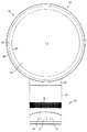
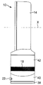
図1は、ファン組立体10の正面図である。ファン組立体10は、好ましくは、ベース12と、ベース12に取り付けられると共にこれによって支持されたノズル14とを有する羽根なしファン組立体の形態をしている。図2aを参照すると、ベース12は、実質的に円筒形の外側ケーシング16を有し、この外側ケーシングは、外側ケーシング16に設けられている孔の形態をした複数個の空気入口18を有し、一次空気流は、外部環境からこれら空気入口を通ってベース12内に引き込まれる。ベース12は、ファン組立体10の動作を制御する複数個のユーザにより操作可能なボタン20及びユーザにより操作可能なダイヤル22を更に有している。この例では、ベース12の高さは、200〜300mmであり、外側ケーシング16の外径は、100〜200mmである。
FIG. 1 is a front view of the
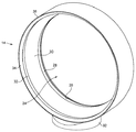
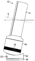
更に図2bを参照すると、ノズル14は、環状の形をしており、このノズルは、中央開口部24を画定又は構成している。ノズル14の高さは、200〜400mmである。ノズル14は、ファン組立体10の後部寄りに設けられていて、空気をファン組立体10から開口部24を通って放出する口(マウス)26を有している。口26は、開口部24周りに少なくとも部分的に延びている。ノズル14の内周部は、口26に隣接して設けられたコアンダ面28を有し、口26は、ファン10から放出された空気をコアンダ面28上でこれに沿って差し向け、ノズル14の内周部は更に、コアンダ面28の下流側に位置するディフューザ面30及びディフューザ面30の上流側に位置する案内面32を有している。ディフューザ面30は、ファン組立体10から放出される空気の流れを助けるために開口部24の中心軸線Xから遠ざかってテーパするよう配置されている。ディフューザ面30と開口部24の中心軸線Xとのなす角度は、5°〜25°であり、この例では約15°である。案内面32は、ファン組立体10からの冷却用空気流の効率的な送り出しを一段と助けるようディフューザ面30に対して角度をなして配置されている。案内面32は、好ましくは、実質的に平らで且つ実質的に滑らかなフェースを口26から放出された空気流に提供するよう開口部24の中心軸線Xに実質的に平行に配置されている。見栄えの良いテーパ付き表面34が、案内面32から見て下流側に設けられており、開口部24の中心軸線Xに実質的に垂直に位置する先端面36で終端している。テーパ面34と開口部24の中心軸線Xとのなす角度は、好ましくは約45°である。開口部24の中心軸線Xに沿って延びる方向におけるノズル24の全深さは、100〜150mmであり、この例では、約110mmである。
Still referring to FIG. 2 b, the
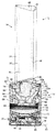
図3は、ファン組立体10の断面図である。ベース12は、下側ベース部材38、下側ベース部材38に取り付けられた中間ベース部材40及び中間ベース部材40に取り付けられた上側ベース部材40を有する。下側ベース部材38は、実質的に平らな底面43を有している。中間ベース部材40は、図1及び図2に示されたユーザにより操作可能なボタン20の押し下げ及び/又はユーザにより操作可能なダイヤル22の操作に応答してファン組立体10の動作を制御するコントローラ44を収容している。中間ベース部材40は、中間ベース部材40及び上側ベース部材40を下側ベース部材38に対して揺動させる揺動機構体46を更に収容するのが良い。上側ベース部材42の各揺動サイクルの範囲は、好ましくは60°〜120°であり、この例では、約90°である。この例では、揺動機構体46は、毎分約3〜5回の揺動サイクルを実施するよう構成されている。電源ケーブル48が、電力をファン組立体10に供給するために下側ベース部材38に形成された孔を貫通している。
FIG. 3 is a cross-sectional view of the
ベース12の上側ベース部材42は、開放上端部を有する。上側ベース部材42は、孔のアレイが形成された円筒形グリルメッシュ50を有している。各孔相互間には、「ランド」と呼ばれる側壁領域が存在している。孔は、ベース12の空気入口18となる。円筒形ベースの全表面積の一部は、孔の全表面積に等しい開放面積である。図示の実施形態では、開放面積は、全メッシュ面積の33%であり、各孔の直径は、1.2mmであり、孔の中心間距離は1.8mmであり、各孔相互間には0.6mmのランドが形成されている。孔開放面積は、空気流がファン組立体中に入るのに必要であるが、孔が大きいと、モータからの振動及び騒音が外部環境に伝わる場合がある。開放面積を約30%〜45%とすることが騒音の放出を阻止するためのランドとファン組立体中への空気の自由で制約されない流入のための開口部との間の妥協策である。
The
上側ベース部材42は、グリルメッシュ50の孔を通って主要空気流量をベース12中に引き込むための羽根車52を収容している。好ましくは、羽根車52は、混流型羽根車の形態をしている。羽根車52は、モータ56から外方に延びる回転シャフト54に連結されている。この例では、モータ56は、ダイヤル22のユーザによる操作に応答して速度がコントローラ44によって変化するDCブラシレスモータである。モータ56の最大速度は、好ましくは、5,000〜10,000rpmである。モータ56は、モータバケット内に収容され、このモータバケットは、上側部分58を下側部分60に連結したものである。モータバケットは、モータバケットリテーナ63により上側ベース部材42内に保持されている。上側ベース部材42の上端部は、円筒形外面65を有している。モータバケットリテーナ63は、例えばスナップ嵌め連結方式により上側ベース部材42の開放上端部に連結されている。モータ56及びそのモータバケットは、モータバケットリテーナ63にはしっかりとは連結されておらず、上側ベース部材42内におけるモータ56の或る程度の運動が可能である。
The
モータバケットリテーナ63は、モータバケットリテーナ63の上端部から内方に延びる湾曲したベーン部分65a,65bを有している。各湾曲ベーン65a,65bは、モータバケットの上方部分58の一部とオーバーラップしている。かくして、モータバケットリテーナ63及び湾曲ベーン65a,65bは、モータバケットを移動及び取り扱い中、固定すると共にこれを定位置に保持するよう働く。特に、モータバケットリテーナ63は、ファン組立体10が逆さまになった場合でも、モータバケットが外れてノズル14に向かって落下するのを阻止する。
The
モータバケットの上側部分58及び下側部分60のうちの一方は、螺旋フィン62aを備えた静止円板の形態をしていて、羽根車52から見て下流側に配置されたディフューザ62を有する。螺旋フィン62aのうちの1つは、上側ベース部材42を垂直に通る線に沿って断面で見て、実質的に逆U字形断面を有する。この螺旋フィン62aは、電力接続ケーブルがフィン62aを貫通することができるよう形作られている。
One of the
モータバケットは、羽根車ハウジング64内に配置されると共にこれに取り付けられている。羽根車ハウジング64は、ベース12の上側ベース部材42内に配置されている複数個の角度間隔を置いた支持体66、この例では3つの支持体に取り付けられている。全体として切頭円錐形のシュラウド68が、羽根車ハウジング64内に設けられている。シュラウド68は、羽根車52の外縁部がシュラウド68の内面に密接するが、これには接触しないよう形作られている。実質的に環状の入口部材70が、一次空気流を羽根車ハウジング64内に案内するために羽根車ハウジング64の底部に連結されている。羽根車ハウジング64の頂部は、羽根車ハウジング64から放出された空気流を案内する実質的に環状の空気出口71を有している。
The motor bucket is disposed within and attached to the
好ましくは、ベース12は、ベース12から出る騒音を減少させる消音化フォームを更に有する。この例では、ベース12の上側ベース部材42は、上側ベース部材42のベース寄りに配置された円板形フォーム部材72及びモータバケット内に配置された実質的に環状のフォーム部材74を有している。
Preferably, the base 12 further has a muffled foam that reduces noise emitted from the
可撓性密封部材が、羽根車ハウジング64に取り付けられている。可撓性密封部材は、外部環境から引き込まれた主要空気流を羽根車52の空気出口71及びディフューザ62から放出された空気流から分離することにより、外側ケーシング16と羽根車ハウジング64との間に延びる経路に沿う空気入口部材70への空気の戻りを阻止する。密封部材は、好ましくは、リップシール76から成る。密封部材は、形状が環状であり、羽根車ハウジング64から外側ケーシング16に向かって外方に延びる状態で羽根車ハウジング64を包囲している。図示の実施形態では、密封部材の直径は、羽根車ハウジング64から外側ケーシング16までの半径方向距離よりも大きい。かくして、密封部材の外側部分77は、外側ケーシング16に押し付けられ、それにより、外側ケーシング16の内面又は内側フェースに沿って延び、リップを形成している。好ましい実施形態のリップシール76は、これが羽根車ハウジング64から遠ざかって外側ケーシング16に向かって延びるにつれて、先端部78までテーパすると共に細まっている。リップシール76は、好ましくは、ゴムで作られている。
A flexible sealing member is attached to the
リップシール76は、電力接続ケーブルをモータ56まで案内する案内部分を更に有している。図示の実施形態の案内部分79は、カラーの形態をしており、この案内部分は、グロメットであるのが良い。
The
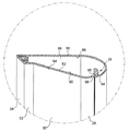
図4は、ノズル14の断面図である。ノズル14は、環状の外側ケーシング区分80を有し、この外側ケーシング区分は、環状の内側ケーシング区分82に連結された状態でこの周りに延びている。これら区分の各々は、複数個の互いに連結された部品で形成されても良いが、この実施形態では、外側ケーシング区分80及び内側ケーシング区分82の各々は、それぞれ単一の成形部品で作られている。内側ケーシング区分82は、ノズル14の中央開口部24を構成し、この内側ケーシング区分は、コアンダ面28、ディフューザ面30、案内面32及びテーパ面34を備えるよう形作られた外周面84を備えている。
FIG. 4 is a cross-sectional view of the
外側ケーシング区分80と内側ケーシング区分82は一緒になって、ノズル14の環状内部通路86を構成している。かくして、内部通路86は、開口部24周りに延びている。内部通路86は、外側ケーシング区分80の内周面88及び内側ケーシング区分82の内周面90によって画定又は構成されている。外側ケーシング区分80は、例えばスナップ嵌め連結方式によってスタンド12の上側ベース部材42の開放上端部に連結されると共にこれを覆っているベース92を有する。外側ケーシング区分80のベース92は、一次空気流がベース12の上側ベース部材42の上端部及びモータバケットリテーナ63の開放上端部からノズル14の内部通路86に流入するようかかる一次空気流を通す孔を有している。
Together, the
ノズル14の口26は、ファン組立体10の後部寄りに配置されている。口26は、外側ケーシング区分80の内周面88及び内側ケーシング区分82の外周面84のそれぞれの互いにオーバーラップした又は向かい合った部分94,96によって画定されている。この例では、口26は、実質的に環状であり、図4に示されているように、この口は、ノズル14を直径方向に通る線に沿って見て実質的にU字形の断面を有する。この例では、外側ケーシング区分80の内周面88及び内側ケーシング区分82の外周面84の互いにオーバーラップした部分94,96は、口26が一次空気流をコアンダ面28上でこれに沿って差し向けるよう構成された出口98に向かってテーパするよう形作られている。出口98は、好ましくは0.5〜5mmの比較的一定の幅を有する環状スロットの形態をしている。この例では、出口98の幅は、約1.0mmである。外側ケーシング区分80の内周面88及び内側ケーシング区分82の外周面84の互いにオーバーラップした部分94,96を互いに押し離して出口98の幅を所望のレベルに維持するためのスペーサが口26の周りに間隔を置いて設けられるのが良い。これらスペーサは、外側ケーシング区分80の内周面88か内側ケーシング区分82の外周面84かのいずれかと一体であるのが良い。
The
次に、図5(a)、図5(b)及び図5(c)を参照すると、上側ベース部材42は、ベース12の中間ベース部材40及び下側ベース部材38に対して、図5(b)に示されている第1の完全傾動位置と図5(c)に示されている第2の完全傾動位置との間で動くことができる。この軸線Xは、好ましくは、本体を図5(a)に示されている非傾動位置からこれら2つの完全傾動位置のうちの一方に動かすと、約10°の角度だけ傾けられる。上側ベース部材42及び中間ベース部材40の外面は、上側ベース部材42が非傾動位置にあるとき、上側ベース部材42及びベース12のこれら外面の隣接部分が互いに実質的に面一をなすよう形作られている。
Next, referring to FIGS. 5A, 5B, and 5C, the
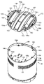
図6を参照すると、中間ベース部材40は、下側ベース部材38に取り付けられた環状下面100、実質的に円筒形の側壁102及び湾曲した上面104を有している。側壁102は、複数個の孔106を有している。ユーザにより操作可能なダイヤル22は、孔106のうちの1つから突き出ており、これに対し、ユーザにより操作可能なボタン20は、他の孔106を介して接近可能である。中間ベース部材40の湾曲した上面104は、形状が凹状であり、全体として鞍形であると形容できる。モータ56から延びる電気ケーブル110(図3に示されている)を受け入れる孔108が、中間ベース部材40の上面104に形成されている。
Referring to FIG. 6, the
図3に戻ってこれを参照すると、電気ケーブル110は、接合部112のところでモータに取り付けられたリボンケーブルである。モータ56から延びる電気ケーブル110は、モータバケットの下側部分60から出て螺旋フィン62aを貫通している。電気ケーブル110の通過経路は、羽根車ハウジング64の形状を辿り、リップシール76の案内部分79は、電気ケーブル110が可撓性密封部材を貫通することができるよう形作られている。リップシール76のカラーにより、電気ケーブルを上側ベース部材42内にクランプしてこれを保持することができる。カフ114が、電気ケーブル110を上側ベース部材42の下側部分内に収容している。
Referring back to FIG. 3, the
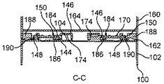
中間ベース部材40は、上側ベース部材42を中間ベース部材40上に支持する4つの支持部材120を更に有している。支持部材120は、中間ベース部材40の上面104から上方に突き出ており、これら支持部材は、これらが互いに実質的に等距離を置くと共に上面104の中心から実質的に等距離を置いて位置するよう配置されている。第1の対をなす支持部材120は、図9(a)にB‐B線に沿って配置され、第2の対をなす支持部材120は、第1の対をなす支持部材120と平行である。さらに図9(b)及び図9(c)を参照すると、各支持部材120は、円筒形外壁122、開放上端部124及び閉鎖下端部126を有している。支持部材120の外壁122は、ボールベアリング(球状支承体)の形態の転動要素128を包囲している。転動要素128は、好ましくは、円筒形外壁122の半径よりも僅かに小さい半径を有し、従って、転動要素128は、支持部材120によって保持された状態でこの中で動くことができるようになっている。転動要素128は、支持部材120の閉鎖下端部126と転動要素128との間に設けられた弾性要素130により中間ベース部材40の上面104から押し離されており、その結果、転動要素128の一部が支持部材120の開放上端部124を越えて突き出るようになっている。この実施形態では、弾性部材130は、コイルばねの形態をしている。
The
図6に戻ってこれを参照すると、中間ベース部材40は、上側ベース部材42を中間ベース部材40上に保持する複数本のレールを更に有している。レールは又、中間ベース部材40に対する上側ベース部材42の運動を案内するのに役立ち、従って、上側ベース部材42を傾動位置から動かし又は傾動位置に動かしているときに、中間ベース部材40に対する上側ベース部材42の捩り又は回転が実質的に生じないようになっている。レールの各々は、軸線Xに実質的に平行な方向に延びている。例えば、レールのうちの1本は、図10(a)に示されたD‐D線に沿って位置している。この実施形態では、複数本のレールは、1対の比較的短い外側レール142相互間に位置した1対の比較的長い内側レール140を有している。さらに図9(b)及び図10(b)を参照すると、内側レール140の各々は、逆L字形の形態の断面を有し、各内側レールは、それぞれの1対の支持部材120相互間に延び、中間ベース部材40の上面104に連結された状態でこれから直立した壁144を有している。内側レール140の各々は、壁144の長さに沿って延びると共に壁144の頂部から隣接の外側案内レール142に向かって直角に突き出た湾曲フランジ146を更に有している。外側レール142の各々も又、逆L字形の形態の断面を有し、各外側レールは、中間ベース部材40の上面に連結された状態でこれから直立した壁148及び壁148の長さに沿って延びると共に壁148の頂部から直角に隣接の内側案内レール140から突き出た湾曲フランジ150を有している。
Referring back to FIG. 6, the
次に図7及び図8を参照すると、上側ベース部材42は、実質的に円筒形の側壁160、環状の下端部162及び凹部を構成するよう上側ベース部材42の下端部162から間隔を置いて位置した湾曲ベース164を有している。グリル50は、好ましくは、側壁160と一体である。上側ベース部材42の側壁160は、中間ベース部材40の側壁102と実質的に同一の外径を有している。ベース164は、形状が凸状であり、一般に逆鞍形を有するものとして形容可能である。ケーブル110が上側ベース部材42のベース164からカフ114内に延びることができるようにする孔166がベース164に形成されている。2対の停止部材168が、ベース164の周囲から上方に延びている(図8に示されている)。停止部材168の各対は、軸線Xに実質的に平行な方向に延びる線に沿って位置している。複数の対をなす停止部材168のうちの1対の停止部材は、図10(a)に示されたD‐D線に沿って位置している。
7 and 8, the
凸状チルトプレート又は傾動板170が、上側ベース部材42のベース164に連結されている。傾動板170は、上側ベース部材42の凹部内に配置されており、この傾動板は、上側ベース部材42のベース164と実質的に同一の曲率を有している。停止部材168の各々は、傾動板170の周囲に沿って設けられた複数個の孔172の各々からそれぞれ突き出ている。傾動板170は、中間ベース部材40の転動要素128に係合する1対の凸状レース174を構成するよう形作られている。各レース174は、軸線Xに実質的に平行な方向に延びており、各レースは、図9(c)に示されているように、対応のそれぞれ1対の支持部材120の転動要素128を受け入れるよう配置されている。
A convex tilt plate or tilting
傾動板170は、複数個のランナを更に有し、これらランナの各々は、中間ベース部材40のそれぞれ対応のレールの下に少なくとも部分的に配置され、かくして、そのレールと協働して上側ベース部材42を中間ベース部材40上に保持すると共に中間ベース部材40に対する上側ベース部材42の運動を案内するよう構成されている。かくして、ランナの各々は、軸線Xに実質的に平行な方向に延びている。例えば、ランナのうちの1つは、図10(a)に示されたD‐D線に沿って位置している。この実施形態では、複数個のランナは、1対の比較的短い外側ランナ182相互間に位置した1対の比較的長い内側ランナ180を含む。さらに図9(b)及び図10(b)を参照すると、内側ランナ180の各々は、逆L字形の形態の断面を有し、各内側ランナは、実質的に垂直の壁184及び壁184の頂部の一部から直角に且つ内方に突き出た湾曲フランジ186を有している。各内側ランナ180の湾曲フランジ186の曲率は、各内側レール140の湾曲フランジ146の曲率と実質的に同一である。外側ランナ182の各々も又、逆L字形の形態の断面を有し、各外側ランナは、実質的に垂直な壁188及び湾曲フランジ190を有し、この湾曲フランジは、壁188の長さに沿って延びると共に壁188の頂部から直角に且つ内方に突き出ている。この場合も又、各外側ランナ182の湾曲フランジ190の曲率は、各外側レール142の湾曲フランジ150の曲率と実質的に同一である。傾動板170は、電気ケーブル110を受け入れる孔192を更に有している。
The
上側ベース部材42を中間ベース部材40に連結するために、傾動板170を図7及び図8に示された向きから逆さまにし、傾動板170のレース174を中間ベース部材40の支持部材120の真後ろにこれと一線をなして配置する。上側ベース部材42の孔166を通って延びている電気ケーブル110を傾動板170及び中間ベース部材40のそれぞれの孔108,192に通し、次に図3に示されているようにコントローラ44に接続するのが良い。次に、傾動板170を中間ベース部材40上でこれに沿って滑らせて転動要素128が図9(b)及び図9(c)に示されているようにレース174に係合するようにし、各外側ランナ182の湾曲フランジ190が図9(b)及び図10(b)に示されているようにそれぞれの外側レール142の湾曲フランジ150の下に配置し、各内側ランナ180の湾曲フランジ186を図9(b)、図10(b)及び図10(c)に示されているようにそれぞれの内側レール140の湾曲フランジ146の下に配置するようにする。
In order to connect the
傾動板170を中間ベース部材40上の中央に位置決めした状態で、上側ベース部材42を傾動板170上に下降させ、停止部材168が傾動板170の孔172内に配置されると共に傾動板170が上側ベース部材42の凹部内に収容されるようにする。次に、中間ベース部材40及び上側ベース部材42を逆さまにし、ベース部材40を軸線Xの方向に沿って変位させて傾動板170に設けられている第1の複数個の孔194aが現われるようにする。これら孔194aの各々を上側ベース部材42のベース164に設けられている管状突出部196aに位置合わせする。セルフタッピンねじを孔194aの各々にねじ込んでこれが下に位置する突出部196aに入るようにし、それにより傾動板170を上側ベース部材42に部分的に連結する。次に、中間ベース部材40を逆方向に変位させて傾動板170に設けられている第2の複数個の孔194bが現われるようにする。これら孔194bの各々も又、上側ベース部材42のベース164に設けられている管状突出部196bに位置合わせする。セルフタッピンねじを孔194bの各々にねじ込んでこれが下に位置する突出部196に入り、それにより上側ベース部材42に対する傾動板170の連結を完了させる。
With the
上側ベース部材42を中間ベース部材40に取り付け、下側ベース部材38の底面43を支持面上に位置決めすると、上側ベース部材42は、支持部材120の転動要素128によって支持される。支持部材120の弾性要素130は、上側ベース部材42を傾動させたときに、中間ベース部材40の上面の擦りを阻止するのに十分な距離だけ転動要素128を支持部材120の閉鎖下端部126から押し離す。例えば、図9(b)、図9(c)、図10(b)及び図10(c)の各々に示されているように、上側ベース部材42の下端部162は、上側ベース部材42を傾動させたときに、中間ベース部材40の上面104との接触が阻止されるようかかる上面から押し離される。さらに、弾性要素130の作用により、ランナの湾曲フランジ186,190の凹状上面がレールの湾曲フランジ146,150の凸状下面に押し付けられる。
When the
上側ベース部材42を中間ベース部材40に対して傾動させるため、ユーザは、上側ベース部材42を軸線Xに平行な方向に滑らせて上側ベース部材42を図5(b)及び図5(c)に示された完全傾動位置のうちの一方に向かって動かし、それにより転動要素128がレース174に沿って動くようにする。上側ベース部材42がいったん所望の位置になると、ユーザは、上側ベース部材42を解除し、この上側ベース部材は、ランナの湾曲フランジ186,190の凹状上面と重力の作用で図5(a)に示された非傾動位置に向かう上側ベース部材42の運動に抵抗するよう作用するレールの湾曲フランジ146,150の凸状下面との間の接触により生じた摩擦力によって所望の位置に保持されている。上側ベース部材42の完全傾動位置は、各対の停止部材168のうちの1つと対応の内側レール140の相互当接によって定められる。
In order to tilt the
ファン組立体10を作動させるため、ユーザは、ベース12のボタン20のうちの適当な1つを押し、これに応答して、コントローラ44は、モータ56を作動させて羽根車52を回す。羽根車52の回転により、一次空気流が空気入口18を通ってベース12内に引き込まれる。一次空気流は、モータの速度に応じて、毎秒20〜30リットルであるのが良い。一次空気流は、羽根車ハウジング64及び上側ベース部材42の上端部及びモータバケットリテーナ63の開放上端部を順次通ってノズル14の内部通路86に入る。空気出口71からの一次空気流の放出方向は、前方且つ上方の方向である。ノズル14内において、一次空気流は、ノズル14の中央開口部24周りに互いに逆方向に進む2つの部分空気流に分割される。ノズル14に側方から流入した一次空気流の一部は、それほど案内されることなく、内部通路86中に側方に入り、ノズル14にX軸線に平行な方向で流入した一次空気流の別の一部は、モータバケットリテーナ63の湾曲ベーン65a,65bによって案内され、それにより一次空気流は、内部通路86中に側方に流入することができる。ベーン65a,65bにより、空気流をX軸線に平行な方向から遠ざかる方向に差し向けることができる。部分空気流は、内部通路86を通過する際、空気は、ノズル14の口26に流入する。口26内への空気流は、好ましくは、ノズル14の開口部24周りにおいて実質的に均等である。口26の各区分内において、部分空気流の一部分の流れ方向が実質的に逆になる。部分空気流の一部分は、口26のテーパ付き区分により絞られ、出口98を通って放出される。
To activate the
口26から放出された一次空気流は、ノズル14のコアンダ面28上でこれに沿って差し向けられ、それにより外部環境からの、特に口26の出口98周りの領域及びノズル14の後部周りからの空気の同伴によって二次空気流が生じる。この二次空気流は、ノズル14の中央開口部24を通り、ここで、二次空気流は、一次空気流と合流し、それによりノズル14から前方に放出される全空気流又は風が生じる。モータ56の速度に応じて、ファン組立体10から前方に放出される空気の流れの質量流量は、毎秒最大400リットル、好ましくは毎秒最大600リットルになる場合があり、送風の最大速度は、2.5〜4m/sになる場合がある。
The primary air flow emitted from the
ノズル14の口26に沿う一次空気流の均等な分布により、空気流は、ディフューザ面30上でこれに沿って一様に流れるようになる。ディフューザ面30により、空気流が膨張の制御された領域を通って動くようになるので空気流の平均速度が減少する。開口部24の中心軸線Xに対するディフューザ面30の比較的浅い角度により、空気流の膨張は、徐々に起こることができる。もしそうでなければ、強烈な又は迅速な広がりにより空気流は、乱れて膨張領域中に渦が生じる。かかる渦により、空気流中に生じる乱流及び関連の騒音が増大する場合があり、このことは、特に家庭用製品、例えばファンでは望ましくない場合がある。ディフューザ面30を越えて前方に放出された空気流は、引き続き広がる傾向がある。開口部30の中心軸線Xに実質的に平行に延びる案内面32が設けられているので、空気流は一段と収斂又は集中する。その結果、空気流は、効率的にノズル14から出て行くことができ、それによりファン組立体10から数メートルの距離を置いたところで空気流を迅速に受けることができる。
Due to the uniform distribution of the primary air flow along the
本発明は、上述の詳細な説明には限定されない。当業者には変形例が明らかであろう。 The present invention is not limited to the above detailed description. Variations will be apparent to those skilled in the art.
例えば、モータバケットリテーナ及び密封部材は、上述した寸法形状とは異なる寸法形状を有して良く、これらは、ファン組立体内に別の位置に配置されても良い。密封部材で気密シールを形成する技術は、別の仕方であっても良く、かかる技術としては、追加の要素、例えばグルー又は取り付け具の使用が挙げられる。密封部材、案内部分、ベーン及びモータバケットリテーナは、適当な強度及び適当な可撓性又は剛性を備えた任意の材料、例えば、フォーム、プラスチック、金属又はゴムで形成できる。ベースに対する上側ベース部材42の運動を電動化し、ユーザがボタン20のうちの1つを押すことによって作動されても良い。
For example, the motor bucket retainer and the sealing member may have a dimensional shape different from the dimensional shape described above, and they may be located at different locations within the fan assembly. Techniques for forming a hermetic seal with the sealing member may be different, such techniques include the use of additional elements, such as glue or fittings. The sealing member, guide portion, vane and motor bucket retainer can be formed of any material with suitable strength and suitable flexibility or rigidity, such as foam, plastic, metal or rubber. The movement of the
10 ファン組立体
12 ベース
14 ノズル
24 開口部
26 口又はマウス
28 コアンダ面
30 ディフューザ面
32 案内面
46 揺動機構体
52 羽根車
56 モータ
62a 螺旋フィン
64 羽根車ハウジング
65a,65b 湾曲ベーン
70 空気入口
76 リップシール
86 内部通路
DESCRIPTION OF
Claims (19)
Applications Claiming Priority (2)
| Application Number | Priority Date | Filing Date | Title |
|---|---|---|---|
| GB0903695A GB2468331B (en) | 2009-03-04 | 2009-03-04 | A fan |
| GB0903695.5 | 2009-03-04 |
Publications (3)
| Publication Number | Publication Date |
|---|---|
| JP2010203442A JP2010203442A (en) | 2010-09-16 |
| JP2010203442A5 JP2010203442A5 (en) | 2011-06-16 |
| JP4773570B2 true JP4773570B2 (en) | 2011-09-14 |
Family
ID=40580592
Family Applications (1)
| Application Number | Title | Priority Date | Filing Date |
|---|---|---|---|
| JP2010065063A Expired - Fee Related JP4773570B2 (en) | 2009-03-04 | 2010-03-02 | Fan assembly |
Country Status (24)
| Country | Link |
|---|---|
| US (4) | US7972111B2 (en) |
| EP (1) | EP2404063B1 (en) |
| JP (1) | JP4773570B2 (en) |
| KR (1) | KR101120536B1 (en) |
| CN (2) | CN201884311U (en) |
| AT (1) | ATE557187T1 (en) |
| AU (2) | AU2010219487B2 (en) |
| BR (1) | BRPI1006047A2 (en) |
| CA (1) | CA2746499C (en) |
| CY (1) | CY1112854T1 (en) |
| DK (1) | DK2404063T3 (en) |
| ES (1) | ES2385303T3 (en) |
| GB (1) | GB2468331B (en) |
| HK (1) | HK1147120A1 (en) |
| HR (1) | HRP20120446T1 (en) |
| IL (1) | IL214533A (en) |
| MY (1) | MY155865A (en) |
| NZ (1) | NZ593320A (en) |
| PL (1) | PL2404063T3 (en) |
| PT (1) | PT2404063E (en) |
| RU (1) | RU2460904C1 (en) |
| SG (1) | SG172130A1 (en) |
| WO (1) | WO2010100452A1 (en) |
| ZA (1) | ZA201107217B (en) |
Families Citing this family (149)
| Publication number | Priority date | Publication date | Assignee | Title |
|---|---|---|---|---|
| FR2919691B1 (en) | 2007-08-03 | 2009-10-30 | Lisi Aerospace Soc Par Actions | SCRAPPING STAPLER AND USE THEREOF FOR TEMPORARILY FIXING A DRILLING GRID ON ASSEMBLED ELEMENTS |
| GB2452593A (en) | 2007-09-04 | 2009-03-11 | Dyson Technology Ltd | A fan |
| GB2463698B (en) | 2008-09-23 | 2010-12-01 | Dyson Technology Ltd | A fan |
| GB2464736A (en) | 2008-10-25 | 2010-04-28 | Dyson Technology Ltd | Fan with a filter |
| GB2466058B (en) | 2008-12-11 | 2010-12-22 | Dyson Technology Ltd | Fan nozzle with spacers |
| PL2265825T3 (en) | 2009-03-04 | 2011-10-31 | Dyson Technology Ltd | A fan assembly |
| GB2468323A (en) | 2009-03-04 | 2010-09-08 | Dyson Technology Ltd | Fan assembly |
| GB2468329A (en) | 2009-03-04 | 2010-09-08 | Dyson Technology Ltd | Fan assembly |
| GB2476171B (en) | 2009-03-04 | 2011-09-07 | Dyson Technology Ltd | Tilting fan stand |
| GB0903682D0 (en) | 2009-03-04 | 2009-04-15 | Dyson Technology Ltd | A fan |
| GB2468325A (en) * | 2009-03-04 | 2010-09-08 | Dyson Technology Ltd | Height adjustable fan with nozzle |
| GB2468326A (en) | 2009-03-04 | 2010-09-08 | Dyson Technology Ltd | Telescopic pedestal fan |
| GB2468331B (en) | 2009-03-04 | 2011-02-16 | Dyson Technology Ltd | A fan |
| GB2468315A (en) | 2009-03-04 | 2010-09-08 | Dyson Technology Ltd | Tilting fan |
| WO2010100462A1 (en) | 2009-03-04 | 2010-09-10 | Dyson Technology Limited | Humidifying apparatus |
| GB2468317A (en) | 2009-03-04 | 2010-09-08 | Dyson Technology Ltd | Height adjustable and oscillating fan |
| GB2468312A (en) | 2009-03-04 | 2010-09-08 | Dyson Technology Ltd | Fan assembly |
| GB2468320C (en) | 2009-03-04 | 2011-06-01 | Dyson Technology Ltd | Tilting fan |
| KR101370271B1 (en) | 2009-03-04 | 2014-03-04 | 다이슨 테크놀러지 리미티드 | A fan |
| EP2404118B1 (en) | 2009-03-04 | 2017-05-31 | Dyson Technology Limited | A fan |
| GB0919473D0 (en) | 2009-11-06 | 2009-12-23 | Dyson Technology Ltd | A fan |
| US9408880B2 (en) | 2013-12-20 | 2016-08-09 | Katherine Rose Kovarik | Method and system for prevention and treatment of allergic and inflammatory diseases |
| US9457077B2 (en) | 2009-11-18 | 2016-10-04 | Katherine Rose Kovarik | Method and system for targeting the microbiome to promote health and treat allergic and inflammatory diseases |
| US9585920B2 (en) | 2011-02-04 | 2017-03-07 | Katherine Rose Kovarik | Method and system for treating cancer cachexia |
| GB2478927B (en) | 2010-03-23 | 2016-09-14 | Dyson Technology Ltd | Portable fan with filter unit |
| GB2478925A (en) | 2010-03-23 | 2011-09-28 | Dyson Technology Ltd | External filter for a fan |
| CA2800681C (en) | 2010-05-27 | 2013-12-10 | Dezheng Li | Device for blowing air by means of narrow slit nozzle assembly |
| GB2482547A (en) | 2010-08-06 | 2012-02-08 | Dyson Technology Ltd | A fan assembly with a heater |
| GB2482549A (en) | 2010-08-06 | 2012-02-08 | Dyson Technology Ltd | A fan assembly with a heater |
| GB2482548A (en) | 2010-08-06 | 2012-02-08 | Dyson Technology Ltd | A fan assembly with a heater |
| GB2483448B (en) | 2010-09-07 | 2015-12-02 | Dyson Technology Ltd | A fan |
| WO2012049470A1 (en) | 2010-10-13 | 2012-04-19 | Dyson Technology Limited | A fan assembly |
| GB2484670B (en) | 2010-10-18 | 2018-04-25 | Dyson Technology Ltd | A fan assembly |
| WO2012052735A1 (en) | 2010-10-18 | 2012-04-26 | Dyson Technology Limited | A fan assembly |
| US9926804B2 (en) | 2010-11-02 | 2018-03-27 | Dyson Technology Limited | Fan assembly |
| GB2486019B (en) | 2010-12-02 | 2013-02-20 | Dyson Technology Ltd | A fan |
| US10548761B2 (en) | 2011-02-04 | 2020-02-04 | Joseph E. Kovarik | Method and system for reducing the likelihood of colorectal cancer in a human being |
| US10085938B2 (en) | 2011-02-04 | 2018-10-02 | Joseph E. Kovarik | Method and system for preventing sore throat in humans |
| US11273187B2 (en) | 2015-11-30 | 2022-03-15 | Joseph E. Kovarik | Method and system for reducing the likelihood of developing depression in an individual |
| US11191665B2 (en) | 2011-02-04 | 2021-12-07 | Joseph E. Kovarik | Method and system for reducing the likelihood of a porphyromonas gingivalis infection in a human being |
| US10687975B2 (en) | 2011-02-04 | 2020-06-23 | Joseph E. Kovarik | Method and system to facilitate the growth of desired bacteria in a human's mouth |
| US10086018B2 (en) | 2011-02-04 | 2018-10-02 | Joseph E. Kovarik | Method and system for reducing the likelihood of colorectal cancer in a human being |
| US11951140B2 (en) | 2011-02-04 | 2024-04-09 | Seed Health, Inc. | Modulation of an individual's gut microbiome to address osteoporosis and bone disease |
| US9987224B2 (en) | 2011-02-04 | 2018-06-05 | Joseph E. Kovarik | Method and system for preventing migraine headaches, cluster headaches and dizziness |
| US11419903B2 (en) | 2015-11-30 | 2022-08-23 | Seed Health, Inc. | Method and system for reducing the likelihood of osteoporosis |
| US9730967B2 (en) | 2011-02-04 | 2017-08-15 | Katherine Rose Kovarik | Method and system for treating cancer cachexia |
| US10245288B2 (en) | 2011-02-04 | 2019-04-02 | Joseph E. Kovarik | Method and system for reducing the likelihood of developing NASH in an individual diagnosed with non-alcoholic fatty liver disease |
| US10842834B2 (en) | 2016-01-06 | 2020-11-24 | Joseph E. Kovarik | Method and system for reducing the likelihood of developing liver cancer in an individual diagnosed with non-alcoholic fatty liver disease |
| US10512661B2 (en) | 2011-02-04 | 2019-12-24 | Joseph E. Kovarik | Method and system for reducing the likelihood of developing liver cancer in an individual diagnosed with non-alcoholic fatty liver disease |
| US11844720B2 (en) | 2011-02-04 | 2023-12-19 | Seed Health, Inc. | Method and system to reduce the likelihood of dental caries and halitosis |
| US10111913B2 (en) | 2011-02-04 | 2018-10-30 | Joseph E. Kovarik | Method of reducing the likelihood of skin cancer in an individual human being |
| US10314865B2 (en) | 2011-02-04 | 2019-06-11 | Katherine Rose Kovarik | Method and system for treating cancer and other age-related diseases by extending the healthspan of a human |
| US11998479B2 (en) | 2011-02-04 | 2024-06-04 | Seed Health, Inc. | Method and system for addressing adverse effects on the oral microbiome and restoring gingival health caused by sodium lauryl sulphate exposure |
| US10835560B2 (en) | 2013-12-20 | 2020-11-17 | Joseph E. Kovarik | Reducing the likelihood of skin cancer in an individual human being |
| US10583033B2 (en) | 2011-02-04 | 2020-03-10 | Katherine Rose Kovarik | Method and system for reducing the likelihood of a porphyromonas gingivalis infection in a human being |
| US11951139B2 (en) | 2015-11-30 | 2024-04-09 | Seed Health, Inc. | Method and system for reducing the likelihood of osteoporosis |
| US10010568B2 (en) | 2011-02-04 | 2018-07-03 | Katherine Rose Kovarik | Method and system for reducing the likelihood of a spirochetes infection in a human being |
| US11523934B2 (en) | 2011-02-04 | 2022-12-13 | Seed Health, Inc. | Method and system to facilitate the growth of desired bacteria in a human's mouth |
| US11357722B2 (en) | 2011-02-04 | 2022-06-14 | Seed Health, Inc. | Method and system for preventing sore throat in humans |
| CN102192198A (en) * | 2011-06-10 | 2011-09-21 | 应辉 | Fan assembly |
| RU2576735C2 (en) | 2011-07-27 | 2016-03-10 | Дайсон Текнолоджи Лимитед | Fan assembly |
| GB2493506B (en) | 2011-07-27 | 2013-09-11 | Dyson Technology Ltd | A fan assembly |
| CN102305220B (en) * | 2011-08-16 | 2015-01-07 | 江西维特科技有限公司 | Low-noise blade-free fan |
| US8899378B2 (en) | 2011-09-13 | 2014-12-02 | Black & Decker Inc. | Compressor intake muffler and filter |
| AU2012216658B2 (en) | 2011-09-13 | 2016-09-15 | Black & Decker Inc | Method of reducing air compressor noise |
| CN102465931B (en) * | 2011-10-08 | 2014-08-20 | 杭州金鱼电器集团有限公司 | Electric fan without fan blades |
| CN102465930B (en) * | 2011-10-08 | 2014-08-20 | 杭州金鱼电器集团有限公司 | Electric fan without fan blades |
| CN103089717A (en) * | 2011-11-01 | 2013-05-08 | 任文华 | Fan component and base for same |
| GB201119500D0 (en) | 2011-11-11 | 2011-12-21 | Dyson Technology Ltd | A fan assembly |
| GB2496877B (en) | 2011-11-24 | 2014-05-07 | Dyson Technology Ltd | A fan assembly |
| KR101880481B1 (en) * | 2011-12-20 | 2018-07-23 | 엘지전자 주식회사 | An air discharging unit |
| GB2498547B (en) * | 2012-01-19 | 2015-02-18 | Dyson Technology Ltd | A fan |
| GB2499044B (en) | 2012-02-06 | 2014-03-19 | Dyson Technology Ltd | A fan |
| GB2499041A (en) | 2012-02-06 | 2013-08-07 | Dyson Technology Ltd | Bladeless fan including an ionizer |
| GB2499042A (en) | 2012-02-06 | 2013-08-07 | Dyson Technology Ltd | A nozzle for a fan assembly |
| GB2512192B (en) | 2012-03-06 | 2015-08-05 | Dyson Technology Ltd | A Humidifying Apparatus |
| GB2500012B (en) | 2012-03-06 | 2016-07-06 | Dyson Technology Ltd | A Humidifying Apparatus |
| GB2500011B (en) | 2012-03-06 | 2016-07-06 | Dyson Technology Ltd | A Humidifying Apparatus |
| GB2500017B (en) | 2012-03-06 | 2015-07-29 | Dyson Technology Ltd | A Humidifying Apparatus |
| GB2500010B (en) | 2012-03-06 | 2016-08-24 | Dyson Technology Ltd | A humidifying apparatus |
| KR101699293B1 (en) | 2012-03-06 | 2017-01-24 | 다이슨 테크놀러지 리미티드 | A fan assembly |
| DE202012002443U1 (en) * | 2012-03-06 | 2012-04-17 | Ds Produkte Gmbh | fan |
| GB2500903B (en) | 2012-04-04 | 2015-06-24 | Dyson Technology Ltd | Heating apparatus |
| CN102661294B (en) * | 2012-04-10 | 2014-10-29 | 宁波宏钜电器科技有限公司 | Bladeless fan |
| GB2501301B (en) | 2012-04-19 | 2016-02-03 | Dyson Technology Ltd | A fan assembly |
| WO2013171452A2 (en) | 2012-05-16 | 2013-11-21 | Dyson Technology Limited | A fan |
| GB2532557B (en) | 2012-05-16 | 2017-01-11 | Dyson Technology Ltd | A fan comprsing means for suppressing noise |
| GB2502103B (en) * | 2012-05-16 | 2015-09-23 | Dyson Technology Ltd | A fan |
| US20130320574A1 (en) * | 2012-05-18 | 2013-12-05 | The Yankee Candle Company, Inc. | Aerodynamic formula dispersing apparatus |
| CN103470543B (en) * | 2012-06-06 | 2015-10-21 | 江西维特科技有限公司 | A kind of without blade fan |
| GB2503907B (en) | 2012-07-11 | 2014-05-28 | Dyson Technology Ltd | A fan assembly |
| CN103629086A (en) * | 2012-08-21 | 2014-03-12 | 任文华 | Fan |
| CN102996476B (en) * | 2012-11-14 | 2015-10-14 | 胡晓存 | Without blade fan |
| BR302013003358S1 (en) | 2013-01-18 | 2014-11-25 | Dyson Technology Ltd | CONFIGURATION APPLIED ON HUMIDIFIER |
| AU350181S (en) | 2013-01-18 | 2013-08-15 | Dyson Technology Ltd | Humidifier or fan |
| AU350179S (en) | 2013-01-18 | 2013-08-15 | Dyson Technology Ltd | Humidifier or fan |
| AU350140S (en) | 2013-01-18 | 2013-08-13 | Dyson Technology Ltd | Humidifier or fan |
| GB2510195B (en) | 2013-01-29 | 2016-04-27 | Dyson Technology Ltd | A fan assembly |
| AU2014211001B2 (en) | 2013-01-29 | 2016-09-15 | Dyson Technology Limited | A fan assembly |
| CA152658S (en) | 2013-03-07 | 2014-05-20 | Dyson Technology Ltd | Fan |
| CA152656S (en) | 2013-03-07 | 2014-05-20 | Dyson Technology Ltd | Fan |
| USD729372S1 (en) | 2013-03-07 | 2015-05-12 | Dyson Technology Limited | Fan |
| BR302013004394S1 (en) | 2013-03-07 | 2014-12-02 | Dyson Technology Ltd | CONFIGURATION APPLIED TO FAN |
| CA152655S (en) | 2013-03-07 | 2014-05-20 | Dyson Technology Ltd | Fan |
| CA152657S (en) | 2013-03-07 | 2014-05-20 | Dyson Technology Ltd | Fan |
| CN103256209B (en) * | 2013-03-22 | 2016-04-06 | 杭州金鱼电器集团有限公司 | A kind of fan component |
| CN104100497B (en) * | 2013-04-08 | 2016-04-20 | 任文华 | Fan |
| GB2530906B (en) | 2013-07-09 | 2017-05-10 | Dyson Technology Ltd | A fan assembly |
| CA154722S (en) | 2013-08-01 | 2015-02-16 | Dyson Technology Ltd | Fan |
| TWD172707S (en) | 2013-08-01 | 2015-12-21 | 戴森科技有限公司 | A fan |
| CA154723S (en) | 2013-08-01 | 2015-02-16 | Dyson Technology Ltd | Fan |
| CN106194673A (en) * | 2013-08-28 | 2016-12-07 | 滁州华尊电气科技有限公司 | A kind of bladeless fan that can blow a cold wind over |
| GB2518638B (en) | 2013-09-26 | 2016-10-12 | Dyson Technology Ltd | Humidifying apparatus |
| US12005085B2 (en) | 2013-12-20 | 2024-06-11 | Seed Health, Inc. | Probiotic method and composition for maintaining a healthy vaginal microbiome |
| US11826388B2 (en) | 2013-12-20 | 2023-11-28 | Seed Health, Inc. | Topical application of Lactobacillus crispatus to ameliorate barrier damage and inflammation |
| US11980643B2 (en) | 2013-12-20 | 2024-05-14 | Seed Health, Inc. | Method and system to modify an individual's gut-brain axis to provide neurocognitive protection |
| US11833177B2 (en) | 2013-12-20 | 2023-12-05 | Seed Health, Inc. | Probiotic to enhance an individual's skin microbiome |
| US11969445B2 (en) | 2013-12-20 | 2024-04-30 | Seed Health, Inc. | Probiotic composition and method for controlling excess weight, obesity, NAFLD and NASH |
| US11998574B2 (en) | 2013-12-20 | 2024-06-04 | Seed Health, Inc. | Method and system for modulating an individual's skin microbiome |
| US11839632B2 (en) | 2013-12-20 | 2023-12-12 | Seed Health, Inc. | Topical application of CRISPR-modified bacteria to treat acne vulgaris |
| GB2528709B (en) | 2014-07-29 | 2017-02-08 | Dyson Technology Ltd | Humidifying apparatus |
| GB2528704A (en) | 2014-07-29 | 2016-02-03 | Dyson Technology Ltd | Humidifying apparatus |
| GB2528708B (en) | 2014-07-29 | 2016-06-29 | Dyson Technology Ltd | A fan assembly |
| CN104564852B (en) * | 2014-12-30 | 2017-03-08 | 广东美的环境电器制造有限公司 | Head for bladeless fan and the bladeless fan with which |
| TWD173930S (en) * | 2015-01-30 | 2016-02-21 | 戴森科技有限公司 | A fan |
| TWD179707S (en) * | 2015-01-30 | 2016-11-21 | 戴森科技有限公司 | A fan |
| TWD173929S (en) * | 2015-01-30 | 2016-02-21 | 戴森科技有限公司 | A fan |
| TWD173931S (en) * | 2015-01-30 | 2016-02-21 | 戴森科技有限公司 | A fan |
| TWD173932S (en) * | 2015-01-30 | 2016-02-21 | 戴森科技有限公司 | A fan |
| TWD173928S (en) * | 2015-01-30 | 2016-02-21 | 戴森科技有限公司 | A fan |
| GB2535224A (en) | 2015-02-13 | 2016-08-17 | Dyson Technology Ltd | A fan |
| GB2535462B (en) | 2015-02-13 | 2018-08-22 | Dyson Technology Ltd | A fan |
| CA2976031A1 (en) | 2015-02-13 | 2016-08-18 | Dyson Technology Limited | A fan assembly |
| GB2535460B (en) | 2015-02-13 | 2017-11-29 | Dyson Technology Ltd | Fan assembly with removable nozzle and filter |
| GB2535225B (en) | 2015-02-13 | 2017-12-20 | Dyson Technology Ltd | A fan |
| GB2537584B (en) | 2015-02-13 | 2019-05-15 | Dyson Technology Ltd | Fan assembly comprising a nozzle releasably retained on a body |
| WO2017033122A1 (en) | 2015-08-21 | 2017-03-02 | Datalogic Ip Tech S.R.L. | Bladeless dust removal system for compact devices |
| US11111913B2 (en) | 2015-10-07 | 2021-09-07 | Black & Decker Inc. | Oil lubricated compressor |
| USD804007S1 (en) * | 2015-11-25 | 2017-11-28 | Vornado Air Llc | Air circulator |
| USD818567S1 (en) * | 2016-02-22 | 2018-05-22 | Darrel LaVerne Burnett | Cylinder shaped heater |
| WO2018058849A1 (en) * | 2016-09-28 | 2018-04-05 | Fang Liu | No-clean smoke exhauster |
| US11540452B2 (en) * | 2016-12-14 | 2023-01-03 | Mankaew MUANCHART | Air movement control and air source device for cultivation |
| CN107636315B (en) * | 2017-03-28 | 2019-05-07 | 美的集团股份有限公司 | Pedestal and bladeless fan |
| US11384956B2 (en) | 2017-05-22 | 2022-07-12 | Sharkninja Operating Llc | Modular fan assembly with articulating nozzle |
| CN209638120U (en) | 2017-10-20 | 2019-11-15 | 创科(澳门离岸商业服务)有限公司 | Fan |
| US10926210B2 (en) | 2018-04-04 | 2021-02-23 | ACCO Brands Corporation | Air purifier with dual exit paths |
| USD913467S1 (en) | 2018-06-12 | 2021-03-16 | ACCO Brands Corporation | Air purifier |
| US11007464B1 (en) | 2020-07-31 | 2021-05-18 | Germfree Laboratories INC | Portable air filtration and air dispersion system and method |
| US11378100B2 (en) | 2020-11-30 | 2022-07-05 | E. Mishan & Sons, Inc. | Oscillating portable fan with removable grille |
Family Cites Families (313)
| Publication number | Priority date | Publication date | Assignee | Title |
|---|---|---|---|---|
| GB601222A (en) | 1944-10-04 | 1948-04-30 | Berkeley & Young Ltd | Improvements in, or relating to, electric fans |
| GB593828A (en) | 1945-06-14 | 1947-10-27 | Dorothy Barker | Improvements in or relating to propeller fans |
| US1357261A (en) | 1918-10-02 | 1920-11-02 | Ladimir H Svoboda | Fan |
| US1767060A (en) * | 1928-10-04 | 1930-06-24 | W H Addington | Electric motor-driven desk fan |
| US2014185A (en) * | 1930-06-25 | 1935-09-10 | Martin Brothers Electric Compa | Drier |
| GB383498A (en) | 1931-03-03 | 1932-11-17 | Spontan Ab | Improvements in or relating to fans, ventilators, or the like |
| US1896869A (en) * | 1931-07-18 | 1933-02-07 | Master Electric Co | Electric fan |
| US2035733A (en) * | 1935-06-10 | 1936-03-31 | Marathon Electric Mfg | Fan motor mounting |
| US2210458A (en) * | 1936-11-16 | 1940-08-06 | Lester S Keilholtz | Method of and apparatus for air conditioning |
| US2115883A (en) * | 1937-04-21 | 1938-05-03 | Sher Samuel | Lamp |
| US2258961A (en) | 1939-07-26 | 1941-10-14 | Prat Daniel Corp | Ejector draft control |
| US2336295A (en) * | 1940-09-25 | 1943-12-07 | Reimuller Caryl | Air diverter |
| GB641622A (en) * | 1942-05-06 | 1950-08-16 | Fernan Oscar Conill | Improvements in or relating to hair drying |
| US2433795A (en) * | 1945-08-18 | 1947-12-30 | Westinghouse Electric Corp | Fan |
| US2476002A (en) | 1946-01-12 | 1949-07-12 | Edward A Stalker | Rotating wing |
| US2547448A (en) * | 1946-02-20 | 1951-04-03 | Demuth Charles | Hot-air space heater |
| US2473325A (en) * | 1946-09-19 | 1949-06-14 | E A Lab Inc | Combined electric fan and air heating means |
| US2544379A (en) * | 1946-11-15 | 1951-03-06 | Oscar J Davenport | Ventilating apparatus |
| US2488467A (en) * | 1947-09-12 | 1949-11-15 | Lisio Salvatore De | Motor-driven fan |
| GB633273A (en) | 1948-02-12 | 1949-12-12 | Albert Richard Ponting | Improvements in or relating to air circulating apparatus |
| US2510132A (en) * | 1948-05-27 | 1950-06-06 | Morrison Hackley | Oscillating fan |
| GB661747A (en) | 1948-12-18 | 1951-11-28 | British Thomson Houston Co Ltd | Improvements in and relating to oscillating fans |
| US2620127A (en) * | 1950-02-28 | 1952-12-02 | Westinghouse Electric Corp | Air translating apparatus |
| US2583374A (en) * | 1950-10-18 | 1952-01-22 | Hydraulic Supply Mfg Company | Exhaust fan |
| FR1033034A (en) | 1951-02-23 | 1953-07-07 | Articulated stabilizer support for fan with flexible propellers and variable speeds | |
| US2813673A (en) | 1953-07-09 | 1957-11-19 | Gilbert Co A C | Tiltable oscillating fan |
| US2838229A (en) * | 1953-10-30 | 1958-06-10 | Roland J Belanger | Electric fan |
| US2765977A (en) | 1954-10-13 | 1956-10-09 | Morrison Hackley | Electric ventilating fans |
| FR1119439A (en) | 1955-02-18 | 1956-06-20 | Enhancements to portable and wall fans | |
| US2830779A (en) * | 1955-02-21 | 1958-04-15 | Lau Blower Co | Fan stand |
| NL110393C (en) * | 1955-11-29 | 1965-01-15 | Bertin & Cie | |
| CH346643A (en) | 1955-12-06 | 1960-05-31 | K Tateishi Arthur | Electric fan |
| US2808198A (en) * | 1956-04-30 | 1957-10-01 | Morrison Hackley | Oscillating fans |
| BE560119A (en) * | 1956-09-13 | |||
| GB863124A (en) | 1956-09-13 | 1961-03-15 | Sebac Nouvelle Sa | New arrangement for putting gases into movement |
| US2922570A (en) * | 1957-12-04 | 1960-01-26 | Burris R Allen | Automatic booster fan and ventilating shield |
| US3004403A (en) | 1960-07-21 | 1961-10-17 | Francis L Laporte | Refrigerated space humidification |
| DE1291090B (en) * | 1963-01-23 | 1969-03-20 | Schmidt Geb Halm Anneliese | Device for generating an air flow |
| DE1457461A1 (en) | 1963-10-01 | 1969-02-20 | Siemens Elektrogeraete Gmbh | Suitcase-shaped hair dryer |
| FR1387334A (en) | 1963-12-21 | 1965-01-29 | Hair dryer capable of blowing hot and cold air separately | |
| US3270655A (en) * | 1964-03-25 | 1966-09-06 | Howard P Guirl | Air curtain door seal |
| US3518776A (en) * | 1967-06-03 | 1970-07-07 | Bremshey & Co | Blower,particularly for hair-drying,laundry-drying or the like |
| US3444817A (en) | 1967-08-23 | 1969-05-20 | William J Caldwell | Fluid pump |
| US3487555A (en) | 1968-01-15 | 1970-01-06 | Hoover Co | Portable hair dryer |
| US3495343A (en) | 1968-02-20 | 1970-02-17 | Rayette Faberge | Apparatus for applying air and vapor to the face and hair |
| US3503138A (en) * | 1969-05-19 | 1970-03-31 | Oster Mfg Co John | Hair dryer |
| GB1278606A (en) | 1969-09-02 | 1972-06-21 | Oberlind Veb Elektroinstall | Improvements in or relating to transverse flow fans |
| US3645007A (en) | 1970-01-14 | 1972-02-29 | Sunbeam Corp | Hair dryer and facial sauna |
| DE2944027A1 (en) * | 1970-07-22 | 1981-05-07 | Erevanskyj politechničeskyj institut imeni Karla Marksa, Erewan | EJECTOR ROOM AIR CONDITIONER OF THE CENTRAL AIR CONDITIONING |
| US3724092A (en) * | 1971-07-12 | 1973-04-03 | Westinghouse Electric Corp | Portable hair dryer |
| GB1403188A (en) | 1971-10-22 | 1975-08-28 | Olin Energy Systems Ltd | Fluid flow inducing apparatus |
| US3743186A (en) * | 1972-03-14 | 1973-07-03 | Src Lab | Air gun |
| US3885891A (en) * | 1972-11-30 | 1975-05-27 | Rockwell International Corp | Compound ejector |
| US3872916A (en) | 1973-04-05 | 1975-03-25 | Int Harvester Co | Fan shroud exit structure |
| US3795367A (en) * | 1973-04-05 | 1974-03-05 | Src Lab | Fluid device using coanda effect |
| US4037991A (en) | 1973-07-26 | 1977-07-26 | The Plessey Company Limited | Fluid-flow assisting devices |
| US3875745A (en) | 1973-09-10 | 1975-04-08 | Wagner Minning Equipment Inc | Venturi exhaust cooler |
| GB1434226A (en) * | 1973-11-02 | 1976-05-05 | Roberts S A | Pumps |
| US3943329A (en) * | 1974-05-17 | 1976-03-09 | Clairol Incorporated | Hair dryer with safety guard air outlet nozzle |
| CA1055344A (en) | 1974-05-17 | 1979-05-29 | International Harvester Company | Heat transfer system employing a coanda effect producing fan shroud exit |
| US4180130A (en) | 1974-05-22 | 1979-12-25 | International Harvester Company | Heat exchange apparatus including a toroidal-type radiator |
| US4184541A (en) | 1974-05-22 | 1980-01-22 | International Harvester Company | Heat exchange apparatus including a toroidal-type radiator |
| DE2525865A1 (en) | 1974-06-11 | 1976-01-02 | Charbonnages De France | FAN |
| GB1593391A (en) * | 1977-01-28 | 1981-07-15 | British Petroleum Co | Flare |
| GB1495013A (en) | 1974-06-25 | 1977-12-14 | British Petroleum Co | Coanda unit |
| DE2451557C2 (en) | 1974-10-30 | 1984-09-06 | Arnold Dipl.-Ing. 8904 Friedberg Scheel | Device for ventilating a occupied zone in a room |
| US4061188A (en) | 1975-01-24 | 1977-12-06 | International Harvester Company | Fan shroud structure |
| US4136735A (en) | 1975-01-24 | 1979-01-30 | International Harvester Company | Heat exchange apparatus including a toroidal-type radiator |
| US4173995A (en) | 1975-02-24 | 1979-11-13 | International Harvester Company | Recirculation barrier for a heat transfer system |
| US4332529A (en) * | 1975-08-11 | 1982-06-01 | Morton Alperin | Jet diffuser ejector |
| US4046492A (en) * | 1976-01-21 | 1977-09-06 | Vortec Corporation | Air flow amplifier |
| DK140426B (en) * | 1976-11-01 | 1979-08-27 | Arborg O J M | Propulsion nozzle for means of transport in air or water. |
| US4113416A (en) | 1977-02-24 | 1978-09-12 | Ishikawajima-Harima Jukogyo Kabushiki Kaisha | Rotary burner |
| JPS56167897A (en) * | 1980-05-28 | 1981-12-23 | Toshiba Corp | Fan |
| IL63292A0 (en) | 1980-07-17 | 1981-10-30 | Gen Conveyors Ltd | Variable geometry jet nozzle |
| MX147915A (en) | 1981-01-30 | 1983-01-31 | Philips Mexicana S A De C V | ELECTRIC FAN |
| US4568243A (en) * | 1981-10-08 | 1986-02-04 | Barry Wright Corporation | Vibration isolating seal for mounting fans and blowers |
| CH662623A5 (en) | 1981-10-08 | 1987-10-15 | Wright Barry Corp | INSTALLATION FRAME FOR A FAN. |
| GB2111125A (en) | 1981-10-13 | 1983-06-29 | Beavair Limited | Apparatus for inducing fluid flow by Coanda effect |
| US4448354A (en) | 1982-07-23 | 1984-05-15 | The United States Of America As Represented By The Secretary Of The Air Force | Axisymmetric thrust augmenting ejector with discrete primary air slot nozzles |
| FR2534983A1 (en) | 1982-10-20 | 1984-04-27 | Chacoux Claude | Jet supersonic compressor |
| US4718870A (en) * | 1983-02-15 | 1988-01-12 | Techmet Corporation | Marine propulsion system |
| US4643351A (en) * | 1984-06-14 | 1987-02-17 | Tokyo Sanyo Electric Co. | Ultrasonic humidifier |
| FR2574854B1 (en) | 1984-12-17 | 1988-10-28 | Peugeot Aciers Et Outillage | MOTOR FAN, PARTICULARLY FOR MOTOR VEHICLE, FIXED ON SOLID BODY SUPPORT ARMS |
| US4630475A (en) | 1985-03-20 | 1986-12-23 | Sharp Kabushiki Kaisha | Fiber optic level sensor for humidifier |
| US4832576A (en) | 1985-05-30 | 1989-05-23 | Sanyo Electric Co., Ltd. | Electric fan |
| US4703152A (en) | 1985-12-11 | 1987-10-27 | Holmes Products Corp. | Tiltable and adjustably oscillatable portable electric heater/fan |
| GB2185533A (en) | 1986-01-08 | 1987-07-22 | Rolls Royce | Ejector pumps |
| GB2185531B (en) | 1986-01-20 | 1989-11-22 | Mitsubishi Electric Corp | Electric fans |
| US4732539A (en) * | 1986-02-14 | 1988-03-22 | Holmes Products Corp. | Oscillating fan |
| US4850804A (en) * | 1986-07-07 | 1989-07-25 | Tatung Company Of America, Inc. | Portable electric fan having a universally adjustable mounting |
| US4790133A (en) | 1986-08-29 | 1988-12-13 | General Electric Company | High bypass ratio counterrotating turbofan engine |
| DE3644567C2 (en) | 1986-12-27 | 1993-11-18 | Ltg Lufttechnische Gmbh | Process for blowing supply air into a room |
| JPH0660638B2 (en) | 1987-10-07 | 1994-08-10 | 松下電器産業株式会社 | Mixed flow impeller |
| JPH0636437Y2 (en) | 1988-04-08 | 1994-09-21 | 耕三 福田 | Air circulation device |
| US4878620A (en) | 1988-05-27 | 1989-11-07 | Tarleton E Russell | Rotary vane nozzle |
| US4978281A (en) | 1988-08-19 | 1990-12-18 | Conger William W Iv | Vibration dampened blower |
| US6293121B1 (en) * | 1988-10-13 | 2001-09-25 | Gaudencio A. Labrador | Water-mist blower cooling system and its new applications |
| FR2640857A1 (en) | 1988-12-27 | 1990-06-29 | Seb Sa | Hairdryer with an air exit flow of modifiable form |
| GB2236804A (en) | 1989-07-26 | 1991-04-17 | Anthony Reginald Robins | Compound nozzle |
| GB2240268A (en) | 1990-01-29 | 1991-07-31 | Wik Far East Limited | Hair dryer |
| US5061405A (en) * | 1990-02-12 | 1991-10-29 | Emerson Electric Co. | Constant humidity evaporative wicking filter humidifier |
| FR2658593B1 (en) | 1990-02-20 | 1992-05-07 | Electricite De France | AIR INLET. |
| GB9005709D0 (en) | 1990-03-14 | 1990-05-09 | S & C Thermofluids Ltd | Coanda flue gas ejectors |
| USD325435S (en) * | 1990-09-24 | 1992-04-14 | Vornado Air Circulation Systems, Inc. | Fan support base |
| SU1793107A1 (en) * | 1990-10-11 | 1993-02-07 | Azerb Ni Elektrotekh | Household fan |
| JPH0499258U (en) * | 1991-01-14 | 1992-08-27 | ||
| CN2085866U (en) | 1991-03-16 | 1991-10-02 | 郭维涛 | Portable electric fan |
| US5188508A (en) * | 1991-05-09 | 1993-02-23 | Comair Rotron, Inc. | Compact fan and impeller |
| JP3146538B2 (en) | 1991-08-08 | 2001-03-19 | 松下電器産業株式会社 | Non-contact height measuring device |
| DE4127134B4 (en) | 1991-08-15 | 2004-07-08 | Papst Licensing Gmbh & Co. Kg | diagonal fan |
| US5168722A (en) * | 1991-08-16 | 1992-12-08 | Walton Enterprises Ii, L.P. | Off-road evaporative air cooler |
| US5296769A (en) * | 1992-01-24 | 1994-03-22 | Electrolux Corporation | Air guide assembly for an electric motor and methods of making |
| US5762661A (en) * | 1992-01-31 | 1998-06-09 | Kleinberger; Itamar C. | Mist-refining humidification system having a multi-direction, mist migration path |
| CN2111392U (en) | 1992-02-26 | 1992-07-29 | 张正光 | Switch device for electric fan |
| JP3113055B2 (en) | 1992-04-09 | 2000-11-27 | 亨 山本 | Sustained-release capsule of isothiocyanate and method for producing the same |
| US5310313A (en) * | 1992-11-23 | 1994-05-10 | Chen C H | Swinging type of electric fan |
| US5411371A (en) | 1992-11-23 | 1995-05-02 | Chen; Cheng-Ho | Swiveling electric fan |
| JP3127331B2 (en) | 1993-03-25 | 2001-01-22 | キヤノン株式会社 | Electrophotographic carrier |
| US5317815A (en) * | 1993-06-15 | 1994-06-07 | Hwang Shyh Jye | Grille assembly for hair driers |
| US5402938A (en) * | 1993-09-17 | 1995-04-04 | Exair Corporation | Fluid amplifier with improved operating range using tapered shim |
| US5425902A (en) * | 1993-11-04 | 1995-06-20 | Tom Miller, Inc. | Method for humidifying air |
| GB2285504A (en) | 1993-12-09 | 1995-07-12 | Alfred Slack | Hot air distribution |
| US5407324A (en) | 1993-12-30 | 1995-04-18 | Compaq Computer Corporation | Side-vented axial fan and associated fabrication methods |
| DE4418014A1 (en) | 1994-05-24 | 1995-11-30 | E E T Umwelt Und Gastechnik Gm | Method of conveying and mixing a first fluid with a second fluid under pressure |
| US5645769A (en) * | 1994-06-17 | 1997-07-08 | Nippondenso Co., Ltd. | Humidified cool wind system for vehicles |
| US5577100A (en) | 1995-01-30 | 1996-11-19 | Telemac Cellular Corporation | Mobile phone with internal accounting |
| DE19510397A1 (en) | 1995-03-22 | 1996-09-26 | Piller Gmbh | Blower unit for car=wash |
| CA2155482A1 (en) | 1995-03-27 | 1996-09-28 | Honeywell Consumer Products, Inc. | Portable electric fan heater |
| US5518370A (en) * | 1995-04-03 | 1996-05-21 | Duracraft Corporation | Portable electric fan with swivel mount |
| FR2735854B1 (en) | 1995-06-22 | 1997-08-01 | Valeo Thermique Moteur Sa | DEVICE FOR ELECTRICALLY CONNECTING A MOTOR-FAN FOR A MOTOR VEHICLE HEAT EXCHANGER |
| US5620633A (en) | 1995-08-17 | 1997-04-15 | Circulair, Inc. | Spray misting device for use with a portable-sized fan |
| US6126393A (en) * | 1995-09-08 | 2000-10-03 | Augustine Medical, Inc. | Low noise air blower unit for inflating blankets |
| CN2251639Y (en) * | 1995-11-15 | 1997-04-09 | 黄进成 | Height adjusting device for fan |
| US5762034A (en) * | 1996-01-16 | 1998-06-09 | Board Of Trustees Operating Michigan State University | Cooling fan shroud |
| US5609473A (en) * | 1996-03-13 | 1997-03-11 | Litvin; Charles | Pivot fan |
| US5649370A (en) * | 1996-03-22 | 1997-07-22 | Russo; Paul | Delivery system diffuser attachment for a hair dryer |
| JP3883604B2 (en) | 1996-04-24 | 2007-02-21 | 株式会社共立 | Blower pipe with silencer |
| JP3267598B2 (en) | 1996-06-25 | 2002-03-18 | 三菱電機株式会社 | Contact image sensor |
| US5783117A (en) | 1997-01-09 | 1998-07-21 | Hunter Fan Company | Evaporative humidifier |
| US5730582A (en) | 1997-01-15 | 1998-03-24 | Essex Turbine Ltd. | Impeller for radial flow devices |
| US5862037A (en) * | 1997-03-03 | 1999-01-19 | Inclose Design, Inc. | PC card for cooling a portable computer |
| DE19712228B4 (en) | 1997-03-24 | 2006-04-13 | Behr Gmbh & Co. Kg | Fastening device for a blower motor |
| JP2987133B2 (en) | 1997-04-25 | 1999-12-06 | 日本電産コパル株式会社 | Axial fan and method for manufacturing blade of axial fan and mold for manufacturing blade of axial fan |
| US6123618A (en) * | 1997-07-31 | 2000-09-26 | Jetfan Australia Pty. Ltd. | Air movement apparatus |
| USD398983S (en) | 1997-08-08 | 1998-09-29 | Vornado Air Circulation Systems, Inc. | Fan |
| US6015274A (en) * | 1997-10-24 | 2000-01-18 | Hunter Fan Company | Low profile ceiling fan having a remote control receiver |
| US6082969A (en) | 1997-12-15 | 2000-07-04 | Caterpillar Inc. | Quiet compact radiator cooling fan |
| US6073881A (en) * | 1998-08-18 | 2000-06-13 | Chen; Chung-Ching | Aerodynamic lift apparatus |
| JP4173587B2 (en) | 1998-10-06 | 2008-10-29 | カルソニックカンセイ株式会社 | Air conditioning control device for brushless motor |
| KR20000032363A (en) | 1998-11-13 | 2000-06-15 | 황한규 | Sound-absorbing material of air conditioner |
| USD415271S (en) * | 1998-12-11 | 1999-10-12 | Holmes Products, Corp. | Fan housing |
| US6269549B1 (en) * | 1999-01-08 | 2001-08-07 | Conair Corporation | Device for drying hair |
| JP2000201723A (en) | 1999-01-11 | 2000-07-25 | Hirokatsu Nakano | Hair dryer with improved hair setting effect |
| US6155782A (en) | 1999-02-01 | 2000-12-05 | Hsu; Chin-Tien | Portable fan |
| US6348106B1 (en) | 1999-04-06 | 2002-02-19 | Oreck Holdings, Llc | Apparatus and method for moving a flow of air and particulate through a vacuum cleaner |
| FR2794195B1 (en) | 1999-05-26 | 2002-10-25 | Moulinex Sa | FAN EQUIPPED WITH AN AIR HANDLE |
| US6386845B1 (en) * | 1999-08-24 | 2002-05-14 | Paul Bedard | Air blower apparatus |
| JP2001128432A (en) | 1999-09-10 | 2001-05-11 | Jianzhun Electric Mach Ind Co Ltd | Ac power supply drive type dc brushless electric motor |
| DE19950245C1 (en) | 1999-10-19 | 2001-05-10 | Ebm Werke Gmbh & Co Kg | Radial fan |
| USD435899S1 (en) * | 1999-11-15 | 2001-01-02 | B.K. Rehkatex (H.K.) Ltd. | Electric fan with clamp |
| DE19955517A1 (en) | 1999-11-18 | 2001-05-23 | Leybold Vakuum Gmbh | High-speed turbopump |
| CA2360344C (en) | 1999-12-06 | 2003-02-18 | The Holmes Group, Inc. | Pivotable heater |
| US6282746B1 (en) * | 1999-12-22 | 2001-09-04 | Auto Butler, Inc. | Blower assembly |
| FR2807117B1 (en) | 2000-03-30 | 2002-12-13 | Technofan | CENTRIFUGAL FAN AND BREATHING ASSISTANCE DEVICE COMPRISING SAME |
| US6427984B1 (en) | 2000-08-11 | 2002-08-06 | Hamilton Beach/Proctor-Silex, Inc. | Evaporative humidifier |
| DE10041805B4 (en) | 2000-08-25 | 2008-06-26 | Conti Temic Microelectronic Gmbh | Cooling device with an air-flowed cooler |
| US6511288B1 (en) | 2000-08-30 | 2003-01-28 | Jakel Incorporated | Two piece blower housing with vibration absorbing bottom piece and mounting flanges |
| JP4526688B2 (en) | 2000-11-06 | 2010-08-18 | ハスクバーナ・ゼノア株式会社 | Wind tube with sound absorbing material and method of manufacturing the same |
| JP3503822B2 (en) | 2001-01-16 | 2004-03-08 | ミネベア株式会社 | Axial fan motor and cooling device |
| JP2002213388A (en) | 2001-01-18 | 2002-07-31 | Mitsubishi Electric Corp | Electric fan |
| JP2002227799A (en) | 2001-02-02 | 2002-08-14 | Honda Motor Co Ltd | Variable flow ejector and fuel cell system equipped with it |
| US6480672B1 (en) * | 2001-03-07 | 2002-11-12 | Holmes Group, Inc. | Flat panel heater |
| US6599088B2 (en) | 2001-09-27 | 2003-07-29 | Borgwarner, Inc. | Dynamically sealing ring fan shroud assembly |
| US20030059307A1 (en) * | 2001-09-27 | 2003-03-27 | Eleobardo Moreno | Fan assembly with desk organizer |
| US6789787B2 (en) | 2001-12-13 | 2004-09-14 | Tommy Stutts | Portable, evaporative cooling unit having a self-contained water supply |
| GB0202835D0 (en) | 2002-02-07 | 2002-03-27 | Johnson Electric Sa | Blower motor |
| ES2198204B1 (en) * | 2002-03-11 | 2005-03-16 | Pablo Gumucio Del Pozo | VERTICAL FAN FOR OUTDOORS AND / OR INTERIOR. |
| EP1345082A1 (en) | 2002-03-15 | 2003-09-17 | ASML Netherlands BV | Lithographic apparatus and device manufacturing method |
| US7014423B2 (en) | 2002-03-30 | 2006-03-21 | University Of Central Florida Research Foundation, Inc. | High efficiency air conditioner condenser fan |
| BR0201397B1 (en) | 2002-04-19 | 2011-10-18 | Mounting arrangement for a cooler fan. | |
| JP2003329273A (en) | 2002-05-08 | 2003-11-19 | Mind Bank:Kk | Mist cold air blower also serving as humidifier |
| US6830433B2 (en) * | 2002-08-05 | 2004-12-14 | Kaz, Inc. | Tower fan |
| US20040049842A1 (en) | 2002-09-13 | 2004-03-18 | Conair Cip, Inc. | Remote control bath mat blower unit |
| US7699580B2 (en) * | 2002-12-18 | 2010-04-20 | Lasko Holdings, Inc. | Portable air moving device |
| US20060199515A1 (en) * | 2002-12-18 | 2006-09-07 | Lasko Holdings, Inc. | Concealed portable fan |
| JP4131169B2 (en) | 2002-12-27 | 2008-08-13 | 松下電工株式会社 | Hair dryer |
| JP2004216221A (en) | 2003-01-10 | 2004-08-05 | Omc:Kk | Atomizing device |
| US20040149881A1 (en) * | 2003-01-31 | 2004-08-05 | Allen David S | Adjustable support structure for air conditioner and the like |
| USD485895S1 (en) * | 2003-04-24 | 2004-01-27 | B.K. Rekhatex (H.K.) Ltd. | Electric fan |
| ATE468491T1 (en) * | 2003-07-15 | 2010-06-15 | Ebm Papst St Georgen Gmbh & Co | FAN ARRANGEMENT AND METHOD FOR PRODUCING SAME |
| US7059826B2 (en) * | 2003-07-25 | 2006-06-13 | Lasko Holdings, Inc. | Multi-directional air circulating fan |
| US20050053465A1 (en) * | 2003-09-04 | 2005-03-10 | Atico International Usa, Inc. | Tower fan assembly with telescopic support column |
| CN2650005Y (en) | 2003-10-23 | 2004-10-20 | 上海复旦申花净化技术股份有限公司 | Humidity-retaining spray machine with softening function |
| WO2005050026A1 (en) | 2003-11-18 | 2005-06-02 | Distributed Thermal Systems Ltd. | Heater fan with integrated flow control element |
| US20050128698A1 (en) * | 2003-12-10 | 2005-06-16 | Huang Cheng Y. | Cooling fan |
| US20050163670A1 (en) * | 2004-01-08 | 2005-07-28 | Stephnie Alleyne | Heat activated air freshener system utilizing auto cigarette lighter |
| JP4478464B2 (en) | 2004-01-15 | 2010-06-09 | 三菱電機株式会社 | Humidifier |
| ZA200500984B (en) | 2004-02-12 | 2005-10-26 | Weir- Envirotech ( Pty) Ltd | Rotary pump |
| CN1680727A (en) | 2004-04-05 | 2005-10-12 | 奇鋐科技股份有限公司 | Controlling circuit of low-voltage high rotating speed rotation with high-voltage activation for DC fan motor |
| US7088913B1 (en) | 2004-06-28 | 2006-08-08 | Jcs/Thg, Llc | Baseboard/upright heater assembly |
| JP5164089B2 (en) | 2004-07-14 | 2013-03-13 | 独立行政法人物質・材料研究機構 | Pt / CeO2 / conductive carbon nanoheteroanode material and method for producing the same |
| DE102004034733A1 (en) | 2004-07-17 | 2006-02-16 | Siemens Ag | Radiator frame with at least one electrically driven fan |
| US8485875B1 (en) | 2004-07-21 | 2013-07-16 | Candyrific, LLC | Novelty hand-held fan and object holder |
| CN2713643Y (en) | 2004-08-05 | 2005-07-27 | 大众电脑股份有限公司 | Heat sink |
| FR2874409B1 (en) | 2004-08-19 | 2006-10-13 | Max Sardou | TUNNEL FAN |
| ITBO20040743A1 (en) | 2004-11-30 | 2005-02-28 | Spal Srl | VENTILATION PLANT, IN PARTICULAR FOR MOTOR VEHICLES |
| CN2888138Y (en) | 2005-01-06 | 2007-04-11 | 拉斯科控股公司 | Space saving vertically oriented fan |
| JP4366330B2 (en) | 2005-03-29 | 2009-11-18 | パナソニック株式会社 | Phosphor layer forming method and forming apparatus, and plasma display panel manufacturing method |
| US20100171465A1 (en) | 2005-06-08 | 2010-07-08 | Belkin International, Inc. | Charging Station Configured To Provide Electrical Power to Electronic Devices And Method Therefor |
| JP2005307985A (en) | 2005-06-17 | 2005-11-04 | Matsushita Electric Ind Co Ltd | Electric blower for vacuum cleaner and vacuum cleaner using same |
| KR100748525B1 (en) | 2005-07-12 | 2007-08-13 | 엘지전자 주식회사 | Multi air conditioner heating and cooling simultaneously and indoor fan control method thereof |
| US7147336B1 (en) * | 2005-07-28 | 2006-12-12 | Ming Shi Chou | Light and fan device combination |
| GB2428569B (en) * | 2005-07-30 | 2009-04-29 | Dyson Technology Ltd | Dryer |
| ATE449912T1 (en) | 2005-08-19 | 2009-12-15 | Ebm Papst St Georgen Gmbh & Co | FAN |
| US7617823B2 (en) | 2005-08-24 | 2009-11-17 | Ric Investments, Llc | Blower mounting assembly |
| CN2835669Y (en) * | 2005-09-16 | 2006-11-08 | 霍树添 | Air blowing mechanism of post type electric fan |
| CN2833197Y (en) | 2005-10-11 | 2006-11-01 | 美的集团有限公司 | Foldable fan |
| FR2892278B1 (en) | 2005-10-25 | 2007-11-30 | Seb Sa | HAIR DRYER COMPRISING A DEVICE FOR MODIFYING THE GEOMETRY OF THE AIR FLOW |
| WO2007048206A1 (en) * | 2005-10-28 | 2007-05-03 | Resmed Ltd | Single or multiple stage blower and nested volute(s) and/or impeller(s) therefor |
| JP4867302B2 (en) | 2005-11-16 | 2012-02-01 | パナソニック株式会社 | Fan |
| JP2007138789A (en) | 2005-11-17 | 2007-06-07 | Matsushita Electric Ind Co Ltd | Electric fan |
| US7455504B2 (en) | 2005-11-23 | 2008-11-25 | Hill Engineering | High efficiency fluid movers |
| JP2008100204A (en) | 2005-12-06 | 2008-05-01 | Akira Tomono | Mist generating apparatus |
| JP4823694B2 (en) | 2006-01-13 | 2011-11-24 | 日本電産コパル株式会社 | Small fan motor |
| US7316540B2 (en) * | 2006-01-18 | 2008-01-08 | Kaz, Incorporated | Rotatable pivot mount for fans and other appliances |
| US7478993B2 (en) | 2006-03-27 | 2009-01-20 | Valeo, Inc. | Cooling fan using Coanda effect to reduce recirculation |
| USD539414S1 (en) * | 2006-03-31 | 2007-03-27 | Kaz, Incorporated | Multi-fan frame |
| US7942646B2 (en) | 2006-05-22 | 2011-05-17 | University of Central Florida Foundation, Inc | Miniature high speed compressor having embedded permanent magnet motor |
| JP5157093B2 (en) | 2006-06-30 | 2013-03-06 | コニカミノルタビジネステクノロジーズ株式会社 | Laser scanning optical device |
| CN201027677Y (en) | 2006-07-25 | 2008-02-27 | 王宝珠 | Novel multifunctional electric fan |
| FR2906980B1 (en) | 2006-10-17 | 2010-02-26 | Seb Sa | HAIR DRYER COMPRISING A FLEXIBLE NOZZLE |
| KR100802115B1 (en) * | 2006-12-07 | 2008-02-11 | 삼성광주전자 주식회사 | Fan motor case |
| US7866958B2 (en) * | 2006-12-25 | 2011-01-11 | Amish Patel | Solar powered fan |
| EP1939456B1 (en) | 2006-12-27 | 2014-03-12 | Pfannenberg GmbH | Air passage device |
| US20080166224A1 (en) | 2007-01-09 | 2008-07-10 | Steve Craig Giffin | Blower housing for climate controlled systems |
| US7806388B2 (en) | 2007-03-28 | 2010-10-05 | Eric Junkel | Handheld water misting fan with improved air flow |
| US8235649B2 (en) | 2007-04-12 | 2012-08-07 | Halla Climate Control Corporation | Blower for vehicles |
| US7762778B2 (en) | 2007-05-17 | 2010-07-27 | Kurz-Kasch, Inc. | Fan impeller |
| JP2008294243A (en) | 2007-05-25 | 2008-12-04 | Mitsubishi Electric Corp | Cooling-fan fixing structure |
| JP5468747B2 (en) * | 2007-06-05 | 2014-04-09 | レスメド・モーター・テクノロジーズ・インコーポレーテッド | Blower with bearing tube |
| US7621984B2 (en) | 2007-06-20 | 2009-11-24 | Head waters R&D, Inc. | Electrostatic filter cartridge for a tower air cleaner |
| CN101350549A (en) * | 2007-07-19 | 2009-01-21 | 瑞格电子股份有限公司 | Running apparatus for ceiling fan |
| US20090026850A1 (en) * | 2007-07-25 | 2009-01-29 | King Jih Enterprise Corp. | Cylindrical oscillating fan |
| US7652439B2 (en) | 2007-08-07 | 2010-01-26 | Air Cool Industrial Co., Ltd. | Changeover device of pull cord control and wireless remote control for a DC brushless-motor ceiling fan |
| GB2452490A (en) | 2007-09-04 | 2009-03-11 | Dyson Technology Ltd | Bladeless fan |
| GB2452593A (en) * | 2007-09-04 | 2009-03-11 | Dyson Technology Ltd | A fan |
| US7540474B1 (en) | 2008-01-15 | 2009-06-02 | Chuan-Pan Huang | UV sterilizing humidifier |
| CN201180678Y (en) | 2008-01-25 | 2009-01-14 | 台达电子工业股份有限公司 | Dynamic balance regulated fan structure |
| DE202008001613U1 (en) * | 2008-01-25 | 2009-06-10 | Ebm-Papst St. Georgen Gmbh & Co. Kg | Fan unit with an axial fan |
| US20090214341A1 (en) | 2008-02-25 | 2009-08-27 | Trevor Craig | Rotatable axial fan |
| CN201221477Y (en) | 2008-05-06 | 2009-04-15 | 王衡 | Charging type fan |
| AU325226S (en) * | 2008-06-06 | 2009-03-24 | Dyson Technology Ltd | Fan head |
| AU325225S (en) * | 2008-06-06 | 2009-03-24 | Dyson Technology Ltd | A fan |
| AU325551S (en) * | 2008-07-19 | 2009-04-03 | Dyson Technology Ltd | Fan head |
| AU325552S (en) * | 2008-07-19 | 2009-04-03 | Dyson Technology Ltd | Fan |
| GB2463698B (en) * | 2008-09-23 | 2010-12-01 | Dyson Technology Ltd | A fan |
| CN201281416Y (en) | 2008-09-26 | 2009-07-29 | 黄志力 | Ultrasonics shaking humidifier |
| GB2464736A (en) | 2008-10-25 | 2010-04-28 | Dyson Technology Ltd | Fan with a filter |
| CA130551S (en) * | 2008-11-07 | 2009-12-31 | Dyson Ltd | Fan |
| JP5112270B2 (en) | 2008-12-05 | 2013-01-09 | パナソニック株式会社 | Scalp care equipment |
| GB2466058B (en) * | 2008-12-11 | 2010-12-22 | Dyson Technology Ltd | Fan nozzle with spacers |
| KR20100072857A (en) | 2008-12-22 | 2010-07-01 | 삼성전자주식회사 | Controlling method of interrupt and potable device using the same |
| CN201349269Y (en) | 2008-12-22 | 2009-11-18 | 康佳集团股份有限公司 | Couple remote controller |
| DE102009007037A1 (en) | 2009-02-02 | 2010-08-05 | GM Global Technology Operations, Inc., Detroit | Discharge nozzle for ventilation device or air-conditioning system for vehicle, has horizontal flow lamellas pivoted around upper horizontal axis and/or lower horizontal axis and comprising curved profile |
| GB2476171B (en) | 2009-03-04 | 2011-09-07 | Dyson Technology Ltd | Tilting fan stand |
| GB2468331B (en) | 2009-03-04 | 2011-02-16 | Dyson Technology Ltd | A fan |
| EP2404118B1 (en) * | 2009-03-04 | 2017-05-31 | Dyson Technology Limited | A fan |
| GB2468312A (en) * | 2009-03-04 | 2010-09-08 | Dyson Technology Ltd | Fan assembly |
| GB2468323A (en) * | 2009-03-04 | 2010-09-08 | Dyson Technology Ltd | Fan assembly |
| GB2468329A (en) * | 2009-03-04 | 2010-09-08 | Dyson Technology Ltd | Fan assembly |
| GB2468320C (en) | 2009-03-04 | 2011-06-01 | Dyson Technology Ltd | Tilting fan |
| KR101370271B1 (en) * | 2009-03-04 | 2014-03-04 | 다이슨 테크놀러지 리미티드 | A fan |
| GB2468326A (en) * | 2009-03-04 | 2010-09-08 | Dyson Technology Ltd | Telescopic pedestal fan |
| GB2468317A (en) * | 2009-03-04 | 2010-09-08 | Dyson Technology Ltd | Height adjustable and oscillating fan |
| GB2468325A (en) * | 2009-03-04 | 2010-09-08 | Dyson Technology Ltd | Height adjustable fan with nozzle |
| GB2468313B (en) | 2009-03-04 | 2012-12-26 | Dyson Technology Ltd | A fan |
| GB2473037A (en) | 2009-08-28 | 2011-03-02 | Dyson Technology Ltd | Humidifying apparatus comprising a fan and a humidifier with a plurality of transducers |
| WO2010100462A1 (en) * | 2009-03-04 | 2010-09-10 | Dyson Technology Limited | Humidifying apparatus |
| PL2265825T3 (en) * | 2009-03-04 | 2011-10-31 | Dyson Technology Ltd | A fan assembly |
| GB0903682D0 (en) | 2009-03-04 | 2009-04-15 | Dyson Technology Ltd | A fan |
| GB2468319B (en) | 2009-03-04 | 2013-04-10 | Dyson Technology Ltd | A fan |
| GB2468328A (en) | 2009-03-04 | 2010-09-08 | Dyson Technology Ltd | Fan assembly with humidifier |
| GB2468315A (en) | 2009-03-04 | 2010-09-08 | Dyson Technology Ltd | Tilting fan |
| CN201502549U (en) | 2009-08-19 | 2010-06-09 | 张钜标 | Fan provided with external storage battery |
| JP5263786B2 (en) | 2009-08-26 | 2013-08-14 | 京セラ株式会社 | Wireless communication system, wireless base station, and control method |
| DE102009044349A1 (en) | 2009-10-28 | 2011-05-05 | Minebea Co., Ltd. | Ventilator arrangement for ventilation of vehicle seat, has diaphragm flexibly interconnecting ventilator housing and frame structure and attached to front end of frame structure such that diaphragm covers front end of frame structure |
| GB0919473D0 (en) * | 2009-11-06 | 2009-12-23 | Dyson Technology Ltd | A fan |
| CN201568337U (en) | 2009-12-15 | 2010-09-01 | 叶建阳 | Electric fan without blade |
| CN101749288B (en) | 2009-12-23 | 2013-08-21 | 杭州玄冰科技有限公司 | Airflow generating method and device |
| TWM394383U (en) | 2010-02-03 | 2010-12-11 | sheng-zhi Yang | Bladeless fan structure |
| GB2479760B (en) | 2010-04-21 | 2015-05-13 | Dyson Technology Ltd | An air treating appliance |
| KR100985378B1 (en) | 2010-04-23 | 2010-10-04 | 윤정훈 | A bladeless fan for air circulation |
| CN201779080U (en) | 2010-05-21 | 2011-03-30 | 海尔集团公司 | Bladeless fan |
| CN201770513U (en) | 2010-08-04 | 2011-03-23 | 美的集团有限公司 | Sterilizing device for ultrasonic humidifier |
| GB2482549A (en) * | 2010-08-06 | 2012-02-08 | Dyson Technology Ltd | A fan assembly with a heater |
| GB2482547A (en) * | 2010-08-06 | 2012-02-08 | Dyson Technology Ltd | A fan assembly with a heater |
| GB2482548A (en) * | 2010-08-06 | 2012-02-08 | Dyson Technology Ltd | A fan assembly with a heater |
| CN201802648U (en) | 2010-08-27 | 2011-04-20 | 海尔集团公司 | Fan without fan blades |
| GB2483448B (en) * | 2010-09-07 | 2015-12-02 | Dyson Technology Ltd | A fan |
| CN101984299A (en) | 2010-09-07 | 2011-03-09 | 林美利 | Electronic ice fan |
| CN201763706U (en) | 2010-09-18 | 2011-03-16 | 任文华 | Non-bladed fan |
| CN201763705U (en) | 2010-09-22 | 2011-03-16 | 任文华 | Fan |
| CN101936310A (en) | 2010-10-04 | 2011-01-05 | 任文华 | Fan without fan blades |
| GB2484670B (en) * | 2010-10-18 | 2018-04-25 | Dyson Technology Ltd | A fan assembly |
| WO2012052735A1 (en) * | 2010-10-18 | 2012-04-26 | Dyson Technology Limited | A fan assembly |
| CN101985948A (en) | 2010-11-27 | 2011-03-16 | 任文华 | Bladeless fan |
| TWM407299U (en) | 2011-01-28 | 2011-07-11 | Zhong Qin Technology Co Ltd | Structural improvement for blade free fan |
| CN102095236B (en) | 2011-02-17 | 2013-04-10 | 曾小颖 | Ventilation device |
| JP5360100B2 (en) | 2011-03-18 | 2013-12-04 | タイヨーエレック株式会社 | Game machine |
| CN202165330U (en) | 2011-06-03 | 2012-03-14 | 刘金泉 | Cooling/heating bladeless fan |
| CN102367813A (en) | 2011-09-30 | 2012-03-07 | 王宁雷 | Nozzle of bladeless fan |
| GB2498547B (en) | 2012-01-19 | 2015-02-18 | Dyson Technology Ltd | A fan |
-
2009
- 2009-03-04 GB GB0903695A patent/GB2468331B/en not_active Expired - Fee Related
-
2010
- 2010-02-18 RU RU2011134489/06A patent/RU2460904C1/en not_active IP Right Cessation
- 2010-02-18 AT AT10706040T patent/ATE557187T1/en active
- 2010-02-18 PT PT10706040T patent/PT2404063E/en unknown
- 2010-02-18 KR KR1020117015012A patent/KR101120536B1/en active IP Right Grant
- 2010-02-18 PL PL10706040T patent/PL2404063T3/en unknown
- 2010-02-18 SG SG2011043197A patent/SG172130A1/en unknown
- 2010-02-18 AU AU2010219487A patent/AU2010219487B2/en not_active Ceased
- 2010-02-18 WO PCT/GB2010/050270 patent/WO2010100452A1/en active Application Filing
- 2010-02-18 MY MYPI2011003000A patent/MY155865A/en unknown
- 2010-02-18 ES ES10706040T patent/ES2385303T3/en active Active
- 2010-02-18 NZ NZ593320A patent/NZ593320A/en not_active IP Right Cessation
- 2010-02-18 DK DK10706040.2T patent/DK2404063T3/en active
- 2010-02-18 EP EP10706040A patent/EP2404063B1/en not_active Not-in-force
- 2010-02-18 CN CN2010900005443U patent/CN201884311U/en not_active Expired - Lifetime
- 2010-02-18 BR BRPI1006047A patent/BRPI1006047A2/en not_active Application Discontinuation
- 2010-02-18 CA CA2746499A patent/CA2746499C/en not_active Expired - Fee Related
- 2010-03-01 US US12/715,076 patent/US7972111B2/en not_active Expired - Fee Related
- 2010-03-02 JP JP2010065063A patent/JP4773570B2/en not_active Expired - Fee Related
- 2010-03-04 CN CN201010130001XA patent/CN101825105B/en active Active
- 2010-11-22 AU AU2010101311A patent/AU2010101311B4/en not_active Revoked
-
2011
- 2011-02-02 HK HK11101113.7A patent/HK1147120A1/en not_active IP Right Cessation
- 2011-05-24 US US13/114,695 patent/US8308432B2/en not_active Expired - Fee Related
- 2011-07-18 IL IL214533A patent/IL214533A/en not_active IP Right Cessation
- 2011-10-03 ZA ZA2011/07217A patent/ZA201107217B/en unknown
-
2012
- 2012-05-24 HR HRP20120446AT patent/HRP20120446T1/en unknown
- 2012-06-08 CY CY20121100524T patent/CY1112854T1/en unknown
- 2012-09-14 US US13/618,711 patent/US8529203B2/en not_active Expired - Fee Related
-
2013
- 2013-08-09 US US13/963,776 patent/US8708650B2/en not_active Expired - Fee Related
Also Published As
Similar Documents
| Publication | Publication Date | Title |
|---|---|---|
| JP4773570B2 (en) | Fan assembly | |
| JP5368606B2 (en) | Fan assembly | |
| JP5068893B2 (en) | Fan assembly | |
| JP5118778B2 (en) | Fan assembly | |
| GB2468318A (en) | Fan assembly with silencing member | |
| SG172131A1 (en) | A fan assembly |
Legal Events
| Date | Code | Title | Description |
|---|---|---|---|
| A521 | Request for written amendment filed |
Free format text: JAPANESE INTERMEDIATE CODE: A523 Effective date: 20110426 |
|
| A871 | Explanation of circumstances concerning accelerated examination |
Free format text: JAPANESE INTERMEDIATE CODE: A871 Effective date: 20110426 |
|
| TRDD | Decision of grant or rejection written | ||
| A975 | Report on accelerated examination |
Free format text: JAPANESE INTERMEDIATE CODE: A971005 Effective date: 20110609 |
|
| A01 | Written decision to grant a patent or to grant a registration (utility model) |
Free format text: JAPANESE INTERMEDIATE CODE: A01 Effective date: 20110616 |
|
| A01 | Written decision to grant a patent or to grant a registration (utility model) |
Free format text: JAPANESE INTERMEDIATE CODE: A01 |
|
| A61 | First payment of annual fees (during grant procedure) |
Free format text: JAPANESE INTERMEDIATE CODE: A61 Effective date: 20110623 |
|
| FPAY | Renewal fee payment (event date is renewal date of database) |
Free format text: PAYMENT UNTIL: 20140701 Year of fee payment: 3 |
|
| R150 | Certificate of patent or registration of utility model |
Ref document number: 4773570 Country of ref document: JP Free format text: JAPANESE INTERMEDIATE CODE: R150 Free format text: JAPANESE INTERMEDIATE CODE: R150 |
|
| R250 | Receipt of annual fees |
Free format text: JAPANESE INTERMEDIATE CODE: R250 |
|
| R250 | Receipt of annual fees |
Free format text: JAPANESE INTERMEDIATE CODE: R250 |
|
| R250 | Receipt of annual fees |
Free format text: JAPANESE INTERMEDIATE CODE: R250 |
|
| R250 | Receipt of annual fees |
Free format text: JAPANESE INTERMEDIATE CODE: R250 |
|
| R250 | Receipt of annual fees |
Free format text: JAPANESE INTERMEDIATE CODE: R250 |
|
| R250 | Receipt of annual fees |
Free format text: JAPANESE INTERMEDIATE CODE: R250 |
|
| LAPS | Cancellation because of no payment of annual fees |