JP4772923B2 - Common rail manufacturing method and common rail - Google Patents
Common rail manufacturing method and common rail Download PDFInfo
- Publication number
- JP4772923B2 JP4772923B2 JP2010525090A JP2010525090A JP4772923B2 JP 4772923 B2 JP4772923 B2 JP 4772923B2 JP 2010525090 A JP2010525090 A JP 2010525090A JP 2010525090 A JP2010525090 A JP 2010525090A JP 4772923 B2 JP4772923 B2 JP 4772923B2
- Authority
- JP
- Japan
- Prior art keywords
- mass
- common rail
- hole
- branch hole
- rail
- Prior art date
- Legal status (The legal status is an assumption and is not a legal conclusion. Google has not performed a legal analysis and makes no representation as to the accuracy of the status listed.)
- Expired - Fee Related
Links
Images


Classifications
-
- F—MECHANICAL ENGINEERING; LIGHTING; HEATING; WEAPONS; BLASTING
- F02—COMBUSTION ENGINES; HOT-GAS OR COMBUSTION-PRODUCT ENGINE PLANTS
- F02M—SUPPLYING COMBUSTION ENGINES IN GENERAL WITH COMBUSTIBLE MIXTURES OR CONSTITUENTS THEREOF
- F02M55/00—Fuel-injection apparatus characterised by their fuel conduits or their venting means; Arrangements of conduits between fuel tank and pump F02M37/00
- F02M55/02—Conduits between injection pumps and injectors, e.g. conduits between pump and common-rail or conduits between common-rail and injectors
- F02M55/025—Common rails
-
- B—PERFORMING OPERATIONS; TRANSPORTING
- B23—MACHINE TOOLS; METAL-WORKING NOT OTHERWISE PROVIDED FOR
- B23K—SOLDERING OR UNSOLDERING; WELDING; CLADDING OR PLATING BY SOLDERING OR WELDING; CUTTING BY APPLYING HEAT LOCALLY, e.g. FLAME CUTTING; WORKING BY LASER BEAM
- B23K20/00—Non-electric welding by applying impact or other pressure, with or without the application of heat, e.g. cladding or plating
- B23K20/22—Non-electric welding by applying impact or other pressure, with or without the application of heat, e.g. cladding or plating taking account of the properties of the materials to be welded
- B23K20/227—Non-electric welding by applying impact or other pressure, with or without the application of heat, e.g. cladding or plating taking account of the properties of the materials to be welded with ferrous layer
-
- C—CHEMISTRY; METALLURGY
- C21—METALLURGY OF IRON
- C21D—MODIFYING THE PHYSICAL STRUCTURE OF FERROUS METALS; GENERAL DEVICES FOR HEAT TREATMENT OF FERROUS OR NON-FERROUS METALS OR ALLOYS; MAKING METAL MALLEABLE, e.g. BY DECARBURISATION OR TEMPERING
- C21D1/00—General methods or devices for heat treatment, e.g. annealing, hardening, quenching or tempering
- C21D1/06—Surface hardening
- C21D1/09—Surface hardening by direct application of electrical or wave energy; by particle radiation
-
- C—CHEMISTRY; METALLURGY
- C21—METALLURGY OF IRON
- C21D—MODIFYING THE PHYSICAL STRUCTURE OF FERROUS METALS; GENERAL DEVICES FOR HEAT TREATMENT OF FERROUS OR NON-FERROUS METALS OR ALLOYS; MAKING METAL MALLEABLE, e.g. BY DECARBURISATION OR TEMPERING
- C21D10/00—Modifying the physical properties by methods other than heat treatment or deformation
- C21D10/005—Modifying the physical properties by methods other than heat treatment or deformation by laser shock processing
-
- C—CHEMISTRY; METALLURGY
- C21—METALLURGY OF IRON
- C21D—MODIFYING THE PHYSICAL STRUCTURE OF FERROUS METALS; GENERAL DEVICES FOR HEAT TREATMENT OF FERROUS OR NON-FERROUS METALS OR ALLOYS; MAKING METAL MALLEABLE, e.g. BY DECARBURISATION OR TEMPERING
- C21D9/00—Heat treatment, e.g. annealing, hardening, quenching or tempering, adapted for particular articles; Furnaces therefor
- C21D9/08—Heat treatment, e.g. annealing, hardening, quenching or tempering, adapted for particular articles; Furnaces therefor for tubular bodies or pipes
-
- C—CHEMISTRY; METALLURGY
- C22—METALLURGY; FERROUS OR NON-FERROUS ALLOYS; TREATMENT OF ALLOYS OR NON-FERROUS METALS
- C22C—ALLOYS
- C22C38/00—Ferrous alloys, e.g. steel alloys
- C22C38/001—Ferrous alloys, e.g. steel alloys containing N
-
- C—CHEMISTRY; METALLURGY
- C22—METALLURGY; FERROUS OR NON-FERROUS ALLOYS; TREATMENT OF ALLOYS OR NON-FERROUS METALS
- C22C—ALLOYS
- C22C38/00—Ferrous alloys, e.g. steel alloys
- C22C38/002—Ferrous alloys, e.g. steel alloys containing In, Mg, or other elements not provided for in one single group C22C38/001 - C22C38/60
-
- C—CHEMISTRY; METALLURGY
- C22—METALLURGY; FERROUS OR NON-FERROUS ALLOYS; TREATMENT OF ALLOYS OR NON-FERROUS METALS
- C22C—ALLOYS
- C22C38/00—Ferrous alloys, e.g. steel alloys
- C22C38/02—Ferrous alloys, e.g. steel alloys containing silicon
-
- C—CHEMISTRY; METALLURGY
- C22—METALLURGY; FERROUS OR NON-FERROUS ALLOYS; TREATMENT OF ALLOYS OR NON-FERROUS METALS
- C22C—ALLOYS
- C22C38/00—Ferrous alloys, e.g. steel alloys
- C22C38/04—Ferrous alloys, e.g. steel alloys containing manganese
-
- C—CHEMISTRY; METALLURGY
- C22—METALLURGY; FERROUS OR NON-FERROUS ALLOYS; TREATMENT OF ALLOYS OR NON-FERROUS METALS
- C22C—ALLOYS
- C22C38/00—Ferrous alloys, e.g. steel alloys
- C22C38/06—Ferrous alloys, e.g. steel alloys containing aluminium
-
- C—CHEMISTRY; METALLURGY
- C22—METALLURGY; FERROUS OR NON-FERROUS ALLOYS; TREATMENT OF ALLOYS OR NON-FERROUS METALS
- C22C—ALLOYS
- C22C38/00—Ferrous alloys, e.g. steel alloys
- C22C38/14—Ferrous alloys, e.g. steel alloys containing titanium or zirconium
-
- B—PERFORMING OPERATIONS; TRANSPORTING
- B23—MACHINE TOOLS; METAL-WORKING NOT OTHERWISE PROVIDED FOR
- B23P—METAL-WORKING NOT OTHERWISE PROVIDED FOR; COMBINED OPERATIONS; UNIVERSAL MACHINE TOOLS
- B23P19/00—Machines for simply fitting together or separating metal parts or objects, or metal and non-metal parts, whether or not involving some deformation; Tools or devices therefor so far as not provided for in other classes
- B23P19/04—Machines for simply fitting together or separating metal parts or objects, or metal and non-metal parts, whether or not involving some deformation; Tools or devices therefor so far as not provided for in other classes for assembling or disassembling parts
- B23P19/042—Machines for simply fitting together or separating metal parts or objects, or metal and non-metal parts, whether or not involving some deformation; Tools or devices therefor so far as not provided for in other classes for assembling or disassembling parts specially adapted for combustion engines
-
- C—CHEMISTRY; METALLURGY
- C21—METALLURGY OF IRON
- C21D—MODIFYING THE PHYSICAL STRUCTURE OF FERROUS METALS; GENERAL DEVICES FOR HEAT TREATMENT OF FERROUS OR NON-FERROUS METALS OR ALLOYS; MAKING METAL MALLEABLE, e.g. BY DECARBURISATION OR TEMPERING
- C21D2261/00—Machining or cutting being involved
-
- C—CHEMISTRY; METALLURGY
- C21—METALLURGY OF IRON
- C21D—MODIFYING THE PHYSICAL STRUCTURE OF FERROUS METALS; GENERAL DEVICES FOR HEAT TREATMENT OF FERROUS OR NON-FERROUS METALS OR ALLOYS; MAKING METAL MALLEABLE, e.g. BY DECARBURISATION OR TEMPERING
- C21D9/00—Heat treatment, e.g. annealing, hardening, quenching or tempering, adapted for particular articles; Furnaces therefor
- C21D9/08—Heat treatment, e.g. annealing, hardening, quenching or tempering, adapted for particular articles; Furnaces therefor for tubular bodies or pipes
- C21D9/14—Heat treatment, e.g. annealing, hardening, quenching or tempering, adapted for particular articles; Furnaces therefor for tubular bodies or pipes wear-resistant or pressure-resistant pipes
-
- F—MECHANICAL ENGINEERING; LIGHTING; HEATING; WEAPONS; BLASTING
- F02—COMBUSTION ENGINES; HOT-GAS OR COMBUSTION-PRODUCT ENGINE PLANTS
- F02M—SUPPLYING COMBUSTION ENGINES IN GENERAL WITH COMBUSTIBLE MIXTURES OR CONSTITUENTS THEREOF
- F02M2200/00—Details of fuel-injection apparatus, not otherwise provided for
- F02M2200/80—Fuel injection apparatus manufacture, repair or assembly
- F02M2200/8084—Fuel injection apparatus manufacture, repair or assembly involving welding or soldering
-
- F—MECHANICAL ENGINEERING; LIGHTING; HEATING; WEAPONS; BLASTING
- F02—COMBUSTION ENGINES; HOT-GAS OR COMBUSTION-PRODUCT ENGINE PLANTS
- F02M—SUPPLYING COMBUSTION ENGINES IN GENERAL WITH COMBUSTIBLE MIXTURES OR CONSTITUENTS THEREOF
- F02M63/00—Other fuel-injection apparatus having pertinent characteristics not provided for in groups F02M39/00 - F02M57/00 or F02M67/00; Details, component parts, or accessories of fuel-injection apparatus, not provided for in, or of interest apart from, the apparatus of groups F02M39/00 - F02M61/00 or F02M67/00; Combination of fuel pump with other devices, e.g. lubricating oil pump
- F02M63/02—Fuel-injection apparatus having several injectors fed by a common pumping element, or having several pumping elements feeding a common injector; Fuel-injection apparatus having provisions for cutting-out pumps, pumping elements, or injectors; Fuel-injection apparatus having provisions for variably interconnecting pumping elements and injectors alternatively
- F02M63/0225—Fuel-injection apparatus having a common rail feeding several injectors ; Means for varying pressure in common rails; Pumps feeding common rails
-
- Y—GENERAL TAGGING OF NEW TECHNOLOGICAL DEVELOPMENTS; GENERAL TAGGING OF CROSS-SECTIONAL TECHNOLOGIES SPANNING OVER SEVERAL SECTIONS OF THE IPC; TECHNICAL SUBJECTS COVERED BY FORMER USPC CROSS-REFERENCE ART COLLECTIONS [XRACs] AND DIGESTS
- Y10—TECHNICAL SUBJECTS COVERED BY FORMER USPC
- Y10T—TECHNICAL SUBJECTS COVERED BY FORMER US CLASSIFICATION
- Y10T29/00—Metal working
- Y10T29/49—Method of mechanical manufacture
- Y10T29/49229—Prime mover or fluid pump making
- Y10T29/49231—I.C. [internal combustion] engine making
-
- Y—GENERAL TAGGING OF NEW TECHNOLOGICAL DEVELOPMENTS; GENERAL TAGGING OF CROSS-SECTIONAL TECHNOLOGIES SPANNING OVER SEVERAL SECTIONS OF THE IPC; TECHNICAL SUBJECTS COVERED BY FORMER USPC CROSS-REFERENCE ART COLLECTIONS [XRACs] AND DIGESTS
- Y10—TECHNICAL SUBJECTS COVERED BY FORMER USPC
- Y10T—TECHNICAL SUBJECTS COVERED BY FORMER US CLASSIFICATION
- Y10T29/00—Metal working
- Y10T29/49—Method of mechanical manufacture
- Y10T29/49718—Repairing
- Y10T29/49721—Repairing with disassembling
- Y10T29/49723—Repairing with disassembling including reconditioning of part
- Y10T29/49725—Repairing with disassembling including reconditioning of part by shaping
- Y10T29/49726—Removing material
- Y10T29/49728—Removing material and by a metallurgical operation, e.g., welding, diffusion bonding, casting
Description
本発明は、ディーゼルエンジンの蓄圧式燃料噴射システムにおけるコモンレールの製造方法およびその製造方法により部分強化されたコモンレールに関する。
本願は、2009年3月12日に、日本に出願された特願2009−059918号に基づき優先権を主張し、その内容をここに援用する。The present invention relates to a method for manufacturing a common rail in an accumulator fuel injection system for a diesel engine, and a common rail partially reinforced by the method.
This application claims priority on March 12, 2009 based on Japanese Patent Application No. 2009-059918 for which it applied to Japan, and uses the content here.
流体通路を持つ機械部品において、流体が通過する管の端や、径が極端に変化する部位においては応力集中が発生しやすく、流体の圧力変動の結果として生ずる疲労破壊が問題となることがある。 In a machine part with a fluid passage, stress concentration tends to occur at the end of a pipe through which the fluid passes or at a part where the diameter changes extremely, and fatigue failure that occurs as a result of fluid pressure fluctuations can be a problem. .
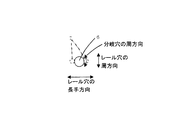
コモンレールは、ディーゼルエンジンの蓄圧式燃料噴射システムにおいて燃料の軽油を圧送するポンプとインジェクターとの間に位置し、軽油を蓄圧するパイプ状の部品である。図1は、コモンレール1の断面の概略を示している。レール穴5がコモンレール1の主なるパイプであり、軽油を蓄圧する役割を有する。レール穴5には垂直に開口する分岐穴6が複数個配設され、分岐穴6を通って各インジェクターに軽油が圧送される。レール穴5の内径d1は10mm程度、分岐穴6の内径d2は1mm程度である。エンジンの作動に伴い、軽油が周期的に圧送され、コモンレール1内の軽油の圧力が周期的に変動する。この際、図1のレール穴5および分岐穴6には、周期的に周方向の引張応力に変動が生じる。図2は、分岐穴6の開口周辺部である分岐穴6の内面とレール穴5の内面との境界周辺部を拡大して示している。分岐穴6開口周辺部の中でも特に、分岐穴6の、レール穴5の長手方向に平行となる直径の両端近傍7では、両穴5、6の引張応力が合成される。このため、他の部分よりも大きな引張応力が発生し、内圧の変動により疲労破壊しやすいという問題がある。内圧の変動に対する疲労強度(内圧疲労強度)を向上させれば、燃料の高圧噴射が可能となり、排気ガスのクリーン化や燃費の向上につながるため、疲労強度向上が望まれている。The common rail is a pipe-like component that is positioned between a pump that pumps light oil of fuel and an injector in a pressure accumulation fuel injection system of a diesel engine, and that accumulates light oil. FIG. 1 schematically shows a cross section of the
従来、このような疲労強度の向上に向けたアプローチとしては、一般的に高強度の鋼材を用いることでコモンレールの疲労強度を高める方法が採られている。しかしながら、このような方法においては、素材の高強度化による成形性や加工性の低下、高性能化に伴うコストの増大の問題が発生している。そのため例えば、特許文献1には、従来の鍛造一体成形及び機械加工によるコモンレールの製造方法に代替する製造方法として、液相拡散接合による溶接コモンレールに関する発明が開示されている。さらに特許文献2には、接合時の制御冷却が不要である液相拡散接合に適した鋼材に関する発明が開示されている。しかし、これらの特許文献に開示されている鋼材は、引張強度が600MPa程度の鋼材であり、近年指向されている高燃費性能を実現するための1500気圧やさらには2000気圧を超えるコモンレールに使用するには強度不足である。また、熱処理等により鋼材強度を著しく向上させることは可能であるが、その場合には加工が困難であり、著しい生産コストの増大を招く。しかも、最大主応力部でMnS、Al2O3、CaO等の介在物や酸化物が加工の結果表面に露呈した場合は、内圧印加時の疲労破壊の起点となり、高強度コモンレールの安定生産を著しく阻害するという課題は解決できない。Conventionally, as an approach for improving the fatigue strength, a method of increasing the fatigue strength of the common rail by using a high-strength steel material is generally employed. However, in such a method, there are problems of a decrease in formability and workability due to an increase in the strength of the material, and an increase in cost due to higher performance. Therefore, for example,
また、鋼材の強度を上げるというオーソドックスな方法のみならず、例えばコモンレールの強化について、特許文献3や特許文献4に開示されているように、流体研磨やコイニング加工の手法を用いて分岐穴開口端部のエッジを面取りして、応力集中を緩和する方法が知られている。また、圧縮応力付与による疲労強度向上も検討されている。近年開発が進められているレーザピーニングは、金属物体の表面に液体等の透明媒質を置いた状態で、その表面へ高いピークパワー密度を持つパルスレーザビームを照射し、そこから発生するプラズマの膨張反力を利用して、金属物体の表面近傍に非接触処理で残留圧縮応力を付与する技術であり、例えば特許文献5にその方法が開示されている。レーザビームは、コモンレールのレール穴内面、分岐穴内面等の狭隘部へも伝送可能であり、レーザピーニングはコモンレールの分岐穴開口部近傍へ高い圧縮応力を付与するための現状唯一の方法である。そこで、特許文献6に開示されたように、レーザピーニングをコモンレールへ適用するための効果的な方法について検討されている。
In addition to the orthodox method of increasing the strength of the steel material, for example, for the reinforcement of the common rail, as disclosed in Patent Document 3 and Patent Document 4, the opening end of the branch hole using a fluid polishing or coining technique. There is known a method of chamfering the edge of a portion to relieve stress concentration. In addition, improvement of fatigue strength by applying compressive stress has been studied. Laser peening, which has been developed in recent years, expands the plasma generated by irradiating a surface of a metal object with a pulsed laser beam having a high peak power density while placing a transparent medium such as a liquid on the surface. This is a technique for applying a residual compressive stress to the vicinity of the surface of a metal object by a non-contact process using a reaction force. For example, Patent Document 5 discloses the method. The laser beam can be transmitted to a narrow part such as the inner surface of the rail hole or the inner surface of the branch hole of the common rail, and laser peening is the only method for applying a high compressive stress to the vicinity of the opening of the branch hole of the common rail. Therefore, as disclosed in
特許文献6に開示された方法は、コモンレールの疲労強度を大きく向上させるが、装置、効果の観点から以下のような問題があった。レーザピーニング処理においてサンプル表面にレーザビームを照射すると、照射スポット部表層近傍が溶融・再凝固することにより、そのスポット部の表層近傍の圧縮応力が減少することが多い。この問題を回避するために、レーザビームを吸収する吸収材料層を設置する方法が知られているが、この吸収材料層をコモンレールの分岐穴開口部へ設置するには複雑な装置を必要とするため、同工程の省略がコストや生産性の観点から望まれる。
The method disclosed in
特許文献5には、熱影響部を除去するための方法として、レーザ光照射面とその近傍に対向して設置した電極間にレーザで制御した放電を生じさせる方法や、レーザ照射面に接する透明液体として電解液を用い、レーザ照射中に照射面とその近傍に対向して設置した電極間で電解研磨を行う方法が開示されている。しかし、これらの方法は、レーザ照射の影響が大きいために、所望の加工形状を精度良く安定的に得ることが難しく、コモンレールの工業生産には適さない。また、特許文献6に開示されているように、パルスレーザのビームスポットの重畳面積割合を高めることで、上述の圧縮応力の減少の問題は緩和される。しかしながら、コモンレールの疲労強度の向上効果をさらに引き上げるためには、表層近傍の圧縮応力を最大限高める必要があり、別のアプローチが望まれている。
In Patent Document 5, as a method for removing the heat-affected zone, a laser-controlled discharge is generated between the laser beam irradiation surface and an electrode disposed in the vicinity thereof, or a transparent surface in contact with the laser irradiation surface. There has been disclosed a method in which an electrolytic solution is used as a liquid and electrolytic polishing is performed between electrodes disposed opposite to an irradiation surface and its vicinity during laser irradiation. However, since these methods are greatly affected by laser irradiation, it is difficult to obtain a desired processed shape accurately and stably, and are not suitable for industrial production of common rails. Further, as disclosed in
本発明は、上記の問題を解決し、応力集中により疲労破壊の起点になりやすいコモンレールの分岐穴の開口部近傍をレーザピーニング処理にて部分的に強化することにより、安価な鋼材を用いて優れた疲労強度を持つコモンレールの製造方法およびコモンレールを提供することを目的とする。 The present invention solves the above-mentioned problems, and by using a laser peening process to partially reinforce the vicinity of the opening of the branch hole of the common rail, which is likely to become a starting point of fatigue failure due to stress concentration, it is excellent using an inexpensive steel material. It is an object to provide a method of manufacturing a common rail having high fatigue strength and a common rail.
本発明は、上記の課題を解決するために以下の手段を採用した。
(1)本発明の第1の態様は、レール穴と、前記レール穴を囲む筒壁部に形成される分岐穴とが設けられるコモンレール本体と、前記分岐穴に連通する連通穴が形成されるホルダーとを備えるコモンレールの液相拡散結合による製造方法である。前記コモンレール本体及び前記ホルダー用の素材は、C:0.01〜0.3質量%、Si:0.01〜0.5質量%、Mn:0.01〜3.0質量%、B:0.0003〜0.01質量%、N:0.001〜0.01質量%、Al:0.01超〜0.5質量%、Ti:0.01〜0.05質量%を含有し、Pが0.03質量%以下に制限され、Sが0.01質量%以下に制限され、Oが0.01質量%以下に制限され、As,Sn,Sb,Pb,Znの総和含有量が0.015質量%以下に制限され、残部がFe及び不可避的不純物を含み、前記コモンレール本体及び前記ホルダー用の素材について、
TLB値=(B%)-[(N%)/1.3-{(Ti%)/3.4+(Al%)/4.1}×(Al%)×52]・・・(1)
で示される、接合時に固溶Bを粒界に偏析させるのに有効な値を表すTLB値が0.001%以上である。このコモンレールの製造方法は、前記コモンレール本体と前記ホルダーとの間に、Bを少なくとも1質量%以上含有するNi基またはFe基のインサートメタルを挿入する挿入工程と;前記コモンレール本体と前記インサートメタルと前記ホルダーとを、接合温度1000〜1300℃で30秒以上の間1MPa以上の応力を負荷して保持して接合する液相拡散接合工程と;前記分岐穴の開口周辺部に位置する前記分岐穴の内面と前記レール穴の内面との境界周辺部の領域に、透明液体を存在させてパルスレーザビームを照射するレーザピーニング処理工程と;前記開口周辺部の表層を除去し、前記開口周辺部の疲労強度を高める表層除去工程と;を備え、
前記レーザピーニング処理を施す領域と前記表層を除去する領域が、それぞれ前記レール穴の内面において、分岐穴の中心からの距離≦分岐穴の直径×0.6・・・(2)および分岐穴の中心方向にレール穴の内面に線分を引いたときの該線分とレール穴の長手方向のなす角≦10°・・・(2’)を満足する領域を包含するものであって、除去する表層の厚みが上記(2)式および上記(2’)式を満足する領域において0.01mm〜0.3mmである。
(2)上記(1)に記載のコモンレールの製造方法では、前記開口周辺部の材料の表層の除去により、前記分岐穴の中心軸を含み前記レール穴の長手方向に沿った断面における前記分岐穴の前記開口部周辺部における形状線の曲率半径が、分岐穴の直径×0.5≦分岐穴の中心からの距離≦分岐穴の直径×0.6・・・(3)を満足する領域の各点において、15μm以上となっていてもよい。
The present invention employs the following means in order to solve the above problems.
(1) In the first aspect of the present invention, a common rail body provided with a rail hole and a branch hole formed in a cylindrical wall portion surrounding the rail hole, and a communication hole communicating with the branch hole are formed. It is a manufacturing method by liquid phase diffusion bonding of a common rail provided with a holder. The material for the common rail main body and the holder is as follows: C: 0.01 to 0.3 mass%, Si: 0.01 to 0.5 mass%, Mn: 0.01 to 3.0 mass%, B: 0 .0003-0.01% by mass, N: 0.001-0.01% by mass, Al: more than 0.01-0.5% by mass, Ti: 0.01-0.05% by mass, P Is limited to 0.03 mass% or less, S is limited to 0.01 mass% or less, O is limited to 0.01 mass% or less, and the total content of As, Sn, Sb, Pb, and Zn is 0. .15% by mass or less, the balance containing Fe and inevitable impurities, and the common rail body and the holder material,
TLB value = (B%)-[(N%) / 1.3-{(Ti%) / 3.4+ (Al%) / 4.1} × (Al%) × 52] ... (1)
The TLB value representing the effective value for segregating the solid solution B to the grain boundary during bonding is 0.001% or more. The common rail manufacturing method includes an insertion step of inserting an Ni-based or Fe-based insert metal containing at least 1% by mass of B between the common rail body and the holder; the common rail body and the insert metal; A liquid phase diffusion bonding step in which the holder is bonded by holding a stress of 1 MPa or more for 30 seconds or more at a bonding temperature of 1000 to 1300 ° C .; and the branch hole located in the periphery of the opening of the branch hole A laser peening process for irradiating a pulsed laser beam in the region around the boundary between the inner surface of the rail and the inner surface of the rail hole; and removing the surface layer around the opening; A surface layer removing step for increasing fatigue strength;
The area to be subjected to the laser peening process and the area from which the surface layer is removed are, on the inner surface of the rail hole, the distance from the center of the branch hole ≦ the diameter of the branch hole × 0.6 (2) and It includes an area that satisfies the angle ≦ 10 ° (2 ′) between the line segment and the longitudinal direction of the rail hole when the line segment is drawn on the inner surface of the rail hole in the center direction, and is removed The thickness of the surface layer is 0.01 mm to 0.3 mm in a region satisfying the above formula (2) and the above formula (2 ′).
(2) In the method for manufacturing a common rail according to (1), the branch hole in a cross section along the longitudinal direction of the rail hole including the central axis of the branch hole is obtained by removing the surface layer of the material around the opening. In the region where the radius of curvature of the shape line in the periphery of the opening satisfies the diameter of the branch hole × 0.5 ≦ the distance from the center of the branch hole ≦ the diameter of the branch hole × 0.6 (3) At each point, it may be 15 μm or more.
(3)上記(1)または(2)に記載のコモンレールの製造方法では、前記コモンレール本体と前記ホルダーとの少なくとも一方が、更に、Ni:0.01〜2.0質量%、Co:0.01〜1.0質量%、Cu:0.01〜1.0質量%、W:0.01〜2.0質量%のうち1種以上を含有してもよい。 ( 3 ) In the method for manufacturing a common rail according to (1) or (2) , at least one of the common rail main body and the holder is further Ni: 0.01 to 2.0 mass%, Co: 0.00. You may contain 1 or more types among 01-1.0 mass%, Cu: 0.01-1.0 mass%, and W: 0.01-2.0 mass%.
(4)上記(1)〜(3)の何れか一項に記載のコモンレールの製造方法では、前記コモンレール本体と前記ホルダーとの少なくとも一方が、更に、Zr:0.001〜0.05質量%、Nb:0.001〜0.05質量%、V:0.001〜0.5質量%のうち1種以上を含有してもよい。 ( 4 ) In the method for manufacturing a common rail according to any one of (1) to (3) , at least one of the common rail body and the holder is further Zr: 0.001 to 0.05% by mass. Nb: 0.001 to 0.05% by mass, V: 0.001 to 0.5% by mass may be contained.
(5)上記(1)〜(4)の何れか一項に記載のコモンレールの製造方法では、前記コモンレール本体と前記ホルダーとの少なくとも一方が、更に、Ca:0.0005〜0.005質量%、Mg:0.0005〜0.005質量%、Ba:0.0005〜0.005質量%のいずれかの硫化物形態制御元素、およびY:0.001〜0.05質量%、Ce:0.001〜0.05質量%、La:0.001〜0.05質量%のいずれかの希土類元素のうち、1種以上を含有してもよい。 ( 5 ) In the method for manufacturing a common rail according to any one of (1) to (4) , at least one of the common rail body and the holder is further Ca: 0.0005 to 0.005 mass%. Mg: 0.0005-0.005 mass%, Ba: 0.0005-0.005 mass% of any sulfide form control element, and Y: 0.001-0.05 mass%, Ce: 0 One or more of rare earth elements of 0.001 to 0.05 mass% and La: 0.001 to 0.05 mass% may be contained.
(6)上記(1)〜(5)のいずれか1項に記載のコモンレールの製造方法では、前記開口周辺部の材料の表層の除去は、電解研磨もしくは流体研磨によって行ってもよい。 ( 6 ) In the method for manufacturing the common rail according to any one of (1) to ( 5 ), the surface layer of the material around the opening may be removed by electrolytic polishing or fluid polishing.
(7)上記(1)〜(6)のいずれか1項に記載のコモンレールの製造方法では、前記パルスレーザビームのパルスエネルギーが1mJ〜10Jであってもよい。 ( 7 ) In the method for manufacturing a common rail described in any one of (1) to ( 6 ) above, the pulse energy of the pulse laser beam may be 1 mJ to 10J.
(8)上記(1)〜(7)のいずれか1項に記載のコモンレールの製造方法では、前記レーザピーニング処理を施す前に、前記開口周辺部を面取り加工してもよい。 ( 8 ) In the method for manufacturing a common rail according to any one of (1) to ( 7 ), the peripheral portion of the opening may be chamfered before the laser peening process is performed.
(9)上記(8)に記載のコモンレールの製造方法では、前記面取り加工を施す領域が、前記(2)式および(2’)式を満足する領域を包含してもよい。 ( 9 ) In the method of manufacturing a common rail described in ( 8 ) above, the area to be chamfered may include an area that satisfies the expressions (2) and (2 ′).
(10)上記(1)〜(9)のいずれか1項に記載のコモンレールの製造方法では、前記レーザピーニング処理に用いる透明液体がアルコール又は防錆剤の入った水であってもよい。 ( 10 ) In the method for producing a common rail according to any one of (1) to ( 9 ), the transparent liquid used for the laser peening treatment may be water containing alcohol or a rust inhibitor.
(11)本発明の第2の態様は、レール穴と、前記レール穴を囲む筒壁部に形成される分岐穴とが設けられるコモンレール本体と、前記分岐穴に連通する連通穴が形成されるホルダーとを備え、上記(1)に記載の液相拡散結合によるコモンレールの製造方法によって製造されたコモンレールである。前記コモンレール本体及び前記ホルダー用の素材は、C:0.01〜0.3質量%、Si:0.01〜0.5質量%、Mn:0.01〜3.0質量%、B:0.0003〜0.01質量%、N:0.001〜0.01質量%、Al:0.01超〜0.5質量%、Ti:0.01〜0.05質量%の成分を含有し、Pが0.03質量%以下に制限され、Sが0.01質量%以下に制限され、Oが0.01質量%以下に制限され、As,Sn,Sb,Pb,Znの総和含有量が0.015質量%以下に制限され、残部がFe及び不可避的不純物を含み、前記コモンレール本体及び前記ホルダー用の素材について、
TLB値=(B%)-[(N%)/1.3-{(Ti%)/3.4+(Al%)/4.1}×(Al%)×52]・・・(1)
で示される、接合時に固溶Bを粒界に偏析させるのに有効な値を表すTLB値が0.001%以上であり、前記開口周辺部における形状が、前記分岐穴の中心軸を含み前記レール穴の長手方向に沿った断面における前記分岐穴の前記開口部周辺部における形状線の曲率半径が、
分岐穴の直径×0.5≦分岐穴の中心からの距離≦分岐穴の直径×0.6・・・(3)
を満足する領域の各点において、15μm以上となり、且つ、前記断面におけるレール穴の長手方向に垂直な圧縮応力値が−200MPa以上である。
(11) In the second aspect of the present invention, a common rail body provided with a rail hole and a branch hole formed in a cylindrical wall portion surrounding the rail hole, and a communication hole communicating with the branch hole are formed. A common rail manufactured by the method for manufacturing a common rail by liquid phase diffusion bonding described in (1) above. The material for the common rail main body and the holder is as follows: C: 0.01 to 0.3 mass%, Si: 0.01 to 0.5 mass%, Mn: 0.01 to 3.0 mass%, B: 0 .0003-0.01% by mass, N: 0.001-0.01% by mass, Al: more than 0.01-0.5% by mass, Ti: 0.01-0.05% by mass , P is limited to 0.03% by mass or less, S is limited to 0.01% by mass or less, O is limited to 0.01% by mass or less, and the total content of As, Sn, Sb, Pb, and Zn Is limited to 0.015 mass% or less, the balance contains Fe and unavoidable impurities, the common rail body and the material for the holder,
TLB value = (B%)-[(N%) / 1.3-{(Ti%) / 3.4+ (Al%) / 4.1} × (Al%) × 52] ... (1)
The TLB value representing a value effective for segregating the solid solution B to the grain boundary during bonding is 0.001% or more, and the shape in the periphery of the opening includes the central axis of the branch hole. The radius of curvature of the shape line in the periphery of the opening of the branch hole in the cross-section along the longitudinal direction of the rail hole,
Diameter of branch hole × 0.5 ≦ Distance from center of branch hole ≦ Diameter of branch hole × 0.6 (3)
The compressive stress value is 15 μm or more at each point in the region satisfying the above and is −200 MPa or more perpendicular to the longitudinal direction of the rail hole in the cross section.
上記(1)〜(11)に記載のコモンレールの製造方法によれば、拡散接合により母材を加工が容易な形状のブロック単位に分けてコモンレールを製造できるので、製造コストを安価にすることができる。また、コモンレールで疲労強度が問題となる分岐穴のレール穴側開口部周辺において、表面から高い圧縮応力が導入できると同時に、分岐穴開口部形状の改善により応力集中が緩和される。その結果、疲労強度を大きく向上させることができる。更に、上記(12)に記載のコモンレールによれば、安価な鋼材を使用して燃料の高圧噴射を行うことが可能となり、排気ガスのクリーン化や燃費の向上が得られ、産業上有用な効果を奏する。 According to the method for manufacturing a common rail described in the above (1) to (11), the common rail can be manufactured by dividing the base material into blocks that can be easily processed by diffusion bonding, so that the manufacturing cost can be reduced. it can. In addition, high compressive stress can be introduced from the surface in the vicinity of the rail hole side opening of the branch hole where fatigue strength is a problem with the common rail, and stress concentration is mitigated by improving the shape of the branch hole opening. As a result, the fatigue strength can be greatly improved. Furthermore, according to the common rail described in the above (12), it is possible to perform high-pressure injection of fuel using an inexpensive steel material, and it is possible to obtain a cleaner exhaust gas and an improvement in fuel consumption. Play.
本発明者らは上記課題を解決するために検討を行った。その結果、液相拡散接合に適した特定の成分を有する高強度鋼材を、加工が容易な形状のブロック単位に分けて製造後、液相拡散接合し、さらに、疲労強度が問題となる分岐穴のレール穴側開口部周辺に対してレーザピーニング処理による圧縮応力導入後に電解研磨等によりレーザピーニング処理した部分を含む領域の材料を除去すれば、安価な鋼材を用いてコモンレールの疲労強度を大きく向上させられることが判った。ここで、液相拡散接合を用いて分岐穴の先に配管を固定するホルダーを接合することは、高強度鋼材の加工を容易にして工程コストを下げる。また、高強度材で致命的な、最大主応力部(分岐穴開口部位)に介在物または酸化物が露出する際に生じる疲労強度の低下を、コモンレール強化用に調整したレーザピーニングによって補完する。従って、従来にない高圧に耐えるコモンレールの製造を安価に実現できる。 The present inventors have studied to solve the above problems. As a result, high-strength steel materials having specific components suitable for liquid phase diffusion bonding are divided into block units with easy-to-process shapes, and then liquid phase diffusion bonding is performed. If the material in the region including the laser peened part by electropolishing etc. is removed after the introduction of compressive stress by laser peening process around the rail hole side opening, the fatigue strength of the common rail is greatly improved by using inexpensive steel I found out that Here, joining the holder that fixes the pipe to the tip of the branch hole using liquid phase diffusion joining facilitates processing of the high-strength steel material and reduces the process cost. In addition, the reduction in fatigue strength that occurs when inclusions or oxides are exposed at the maximum principal stress portion (branch hole opening site), which is fatal for high-strength materials, is complemented by laser peening adjusted for strengthening the common rail. Therefore, the manufacture of a common rail that can withstand a high pressure that has not been conventionally possible can be realized at low cost.
以下に、本発明の好ましい実施形態に係るコモンレールの製造方法およびコモンレールについて、図面に基づいて説明する。なお、本明細書および図面において、実質的に同一の機能構成を有する要素においては、同一の符号を付することにより重複説明を省略する。 Below, the manufacturing method and common rail of the common rail which concern on preferable embodiment of this invention are demonstrated based on drawing. In the present specification and drawings, elements having substantially the same functional configuration are denoted by the same reference numerals, and redundant description is omitted.
図1はコモンレール1の断面の概略を示している。筒壁部2内に形成されるレール穴5がコモンレール1の主なるパイプであり、軽油を蓄圧する役割を有する。レール穴5には、垂直に開口する分岐穴6が複数個配設されている。
FIG. 1 schematically shows a cross section of the
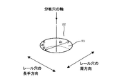
本発明では、コモンレール1を安価に製造するために、液相拡散接合による溶接を行う。具体的には、まず、図3に示すように、長手方向に貫通する管路13を有するコモンレール本体11と円筒形のホルダー12とで形成されるリング状の接合面間に、液相拡散接合用の非晶質合金箔(インサートメタル)15を介在させて、支管14に円筒形のホルダー12を連通させる。そして、抵抗溶接等により、合金箔15とコモンレール本体11とホルダー12とを溶融圧接して、液相拡散接合を行い、継ぎ手部を形成する。なお、図3は、便宜上、1つの支管14のみを示しているが、通常は、エンジン燃焼室の複数の噴射ノズルに対応する複数の支管14を備えている。そして、ホルダー12は、これらの支管14と、エンジン燃焼室の噴射ノズルまで燃料を圧送するための配管とを接続するために、コモンレール本体11の支管14に対応して複数設けられている。このように形成されたコモンレール1において、図3の管路13が図1のレール穴5に対応し、図3の支管14の内部が図1の分岐穴6に対応する。液相拡散接合用の合金箔15には、Bを少なくとも1%以上含有するNi基またはFe基のインサートメタルを用いる。また、コモンレール本体11とホルダー12との液相拡散接合は、接合温度1000〜1300℃で30秒以上の間1MPa以上の応力を負荷して保持することによって行われる。
In the present invention, in order to manufacture the
本実施形態では、液相拡散接合後の制御冷却を要さずとも十分な低温変態組織、すなわち材料の必要な部位あるいは全体にわたってベイナイトもしくはマルテンサイト変態を誘起させ得る焼き入れ性の高い材料を、予め継手設計の段階から選択する。即ち、液相拡散接合で形成される等温凝固継手部位においても十分に均質な組織を得られる合金組成の鋼材がコモンレール1の素材として用いられる。具体的には、上記した例で言えば、コモンレール本体11とホルダー12の素材として、以下に説明する液相拡散接合用鋼を用いる。以下に、液相拡散接合用鋼の化学成分について、好ましい含有量の範囲について説明する。なお、以下に述べる化学成分の含有量はいずれも質量%で示される。
In the present embodiment, a sufficiently low-temperature transformation structure without requiring controlled cooling after liquid phase diffusion bonding, that is, a material with high hardenability capable of inducing bainite or martensite transformation over a necessary part or the whole of the material, Select from the joint design stage in advance. That is, a steel material having an alloy composition capable of obtaining a sufficiently homogeneous structure is used as a material for the
Cは、鋼の焼き入れ性と強度を制御する最も基本的な元素である。含有量が0.01%未満の場合では強度が確保できず、0.3%を超える場合では鋼材の強度が向上するものの、継手の靭性が確保できない。従って、Cの含有量は0.01〜0.3%の範囲に規定される。この範囲の含有量であれば、鋼材の組織制御は接合まま材でも可能である。ただし、炭素の効果を工業的に安定して得るためには、含有量が0.05〜0.3%であることが好ましい。 C is the most basic element that controls the hardenability and strength of steel. When the content is less than 0.01%, the strength cannot be ensured, and when it exceeds 0.3%, the strength of the steel material is improved, but the toughness of the joint cannot be ensured. Therefore, the C content is specified in the range of 0.01 to 0.3%. If the content is within this range, the structure control of the steel material can be performed with the material being joined. However, in order to obtain the carbon effect industrially stably, the content is preferably 0.05 to 0.3%.
Siは、鋼材の脱酸元素であり、通常Mnとともに鋼の酸素濃度を低減する目的で添加される。同時に、Siは粒内強化に必要な元素であるため、その不足は鋼材の強度を低下させる。従って、本発明においても脱酸と粒内強化を主目的として所定量のSiを含有させる。Siの含有量が0.01%以上であれば上述の効果を発揮し、0.5%を超える場合には鋼材そのものの脆化を招く場合がある。従って、Siの含有量は0.01〜0.5%の範囲に規定される。また、液相拡散接合継手においてSiO2を含む複合酸化物、例えばSiO2−MnO、SiO2−FeO等が生成する虞があることから、Siの含有量は0.01〜0.3%であることが好ましい。Si is a deoxidizing element for steel and is usually added together with Mn for the purpose of reducing the oxygen concentration of the steel. At the same time, since Si is an element necessary for intragranular strengthening, the shortage reduces the strength of the steel material. Therefore, also in the present invention, a predetermined amount of Si is contained mainly for deoxidation and intragranular strengthening. If the Si content is 0.01% or more, the above effect is exhibited, and if it exceeds 0.5%, the steel material itself may be embrittled. Accordingly, the Si content is specified in the range of 0.01 to 0.5%. The composite oxide containing SiO 2 in the liquid phase diffusion bonded joint, for example, SiO 2 -MnO, since there is a fear that SiO 2 -FeO like is produced, the content of Si is 0.01 to 0.3% Preferably there is.
Mnは、Siとともに脱酸にも効用があるが、鋼中に添加することで鋼材の焼き入れ性を高め、強度向上に寄与する。Mnの含有量が0.01%以上の場合、上述の効果を発現するが、3.0%を超えると粗大なMnO系酸化物を晶出し、かえって液相拡散接合継手の靭性を低下させる場合がある。従って、Mnの含有量は0.01〜3.0%の範囲に規定される。Mnの含有量についても前記Siと同様にSiO2−MnO生成の抑制の観点からは0.01〜2.0%であることが好ましい。Mn has an effect on deoxidation together with Si, but by adding it to steel, it enhances the hardenability of the steel material and contributes to the improvement of strength. When the content of Mn is 0.01% or more, the above-mentioned effect is exhibited, but when it exceeds 3.0%, a coarse MnO-based oxide is crystallized, and on the contrary, the toughness of the liquid phase diffusion joint is lowered. There is. Therefore, the Mn content is specified in the range of 0.01 to 3.0%. The content of Mn is preferably 0.01 to 2.0% from the viewpoint of suppressing the generation of SiO 2 —MnO as in the case of Si.
Bは、微量で鋼の焼き入れ性を高めるのに極めて効果があるが、その含有量が0.0003%未満では焼き入れ性向上効果は小さい。一方、Bの含有量が0.01%を超える場合、炭硼化物を形成して、かえって液相拡散接合継手の焼き入れ性を低下させて継手強度が低下する。従って、Bの含有量は0.0003〜0.01%の範囲に規定される。一方でBは粒界偏析が著しく、接合後の冷却条件によっては粒界のみに限って脆化を招く場合があるため、その含有量が0.0003〜0.005%であると好ましい。 B is extremely effective in enhancing the hardenability of steel in a small amount, but if its content is less than 0.0003%, the effect of improving hardenability is small. On the other hand, when the content of B exceeds 0.01%, a boride is formed, and on the contrary, the hardenability of the liquid phase diffusion bonding joint is lowered and the joint strength is lowered. Therefore, the B content is specified in the range of 0.0003 to 0.01%. On the other hand, B has a remarkable segregation at the grain boundary, and depending on the cooling conditions after joining, it may cause embrittlement only at the grain boundary, so the content is preferably 0.0003 to 0.005%.
Tiは、BよりもNと結合する力が強く、Bより優先的にNと結合する。したがって、Tiは焼き入れ性に有効な固溶Bを確保するに重要な元素であるが、含有量が0.01%未満の場合にはその効果は小さい。一方、Tiの含有量が0.05%を超える場合には、その効果は飽和するのみならず、粗大なTi系炭窒化物が多数析出して靭性を低下させることになる。したがって、Tiの含有量は、0.01〜0.05%の範囲に規定される。Tiも硼化物を形成する元素であるため、含有量の上限値は可能であれば低く抑制すべきであり、好ましくは0.01〜0.03%である。 Ti has a stronger bonding force with N than B, and bonds with N preferentially over B. Therefore, Ti is an important element for securing solid solution B effective for hardenability, but the effect is small when the content is less than 0.01%. On the other hand, when the Ti content exceeds 0.05%, the effect is not only saturated, but a large number of coarse Ti-based carbonitrides are precipitated to reduce toughness. Therefore, the Ti content is specified in the range of 0.01 to 0.05%. Since Ti is also an element forming a boride, the upper limit of the content should be suppressed as low as possible, preferably 0.01 to 0.03%.
Nは、本実施形態において、上述のBの効果を高めるためには低く抑制することが望ましい元素であるが、AlやTiを添加している場合はこれらと結合してAlN、TiNなどの窒化物を析出し、結晶粒を微細化し鋼の靭性を高めるのに有効である。Nの含有量が0.001%未満の場合、その効果は小さい。また、Nの含有量が0.01%を超える場合、Bと結合してBNを生成する傾向が強くなり、AlまたはTiを大量に添加しないと固溶Bを獲得できない。すなわち、後で説明するTLB値を安定して0.001以上とすることが困難となるので、Nの含有量は0.001〜0.01%の範囲に規定される。なお、通常の製鋼工程でNを安定的に0.008%以上含有させることは工程上のコストが上昇するため、Nの含有量が0.001〜0.008%であることが好ましい。 In this embodiment, N is an element that is desirably suppressed to be low in order to enhance the above-described effect of B. However, when Al or Ti is added, N is combined with these to nitride AlN, TiN, or the like. It is effective for precipitating materials, refining crystal grains and enhancing the toughness of steel. When the content of N is less than 0.001%, the effect is small. Further, when the N content exceeds 0.01%, the tendency to combine with B to form BN becomes strong, and solid solution B cannot be obtained unless a large amount of Al or Ti is added. That is, since it becomes difficult to stably set the TLB value described later to 0.001 or more, the N content is specified in the range of 0.001 to 0.01%. In addition, it is preferable that the content of N is 0.001 to 0.008% because the cost in the process increases when N is stably contained by 0.008% or more in a normal steelmaking process.
Alは、Nと結合して微細なAlNを析出して結晶粒を微細化するとともに、Bを焼き入れ性に有効な固溶Bとして鋼中に確保するに重要な元素である。しかしながら、このような効果を発揮させるためにはAlの含有量が0.01%超であることが好ましい。しかし、Alの含有量が0.5%を超える場合、AlNが粗大化して鋼の靭性を低下させる。したがって、Alの含有量は0.01超〜0.5%の範囲に規定される。ただし、AlはOとの親和力も高く、大量添加時には製鋼工程によっては粗大酸化物クラスターを生成し、継手の靱性を低下させる場合がある。従って、Alの含有量は0.01%超〜0.3%であることが好ましい。 Al combines with N to precipitate fine AlN to refine crystal grains, and is an important element for securing B in the steel as a solid solution B effective for hardenability. However, in order to exert such an effect, the Al content is preferably more than 0.01%. However, when the Al content exceeds 0.5%, AlN becomes coarse and lowers the toughness of the steel. Therefore, the Al content is specified in the range of more than 0.01 to 0.5%. However, Al has a high affinity with O, and when added in a large amount, a coarse oxide cluster may be generated depending on the steel making process, and the toughness of the joint may be lowered. Therefore, the Al content is preferably more than 0.01% to 0.3%.
なお、本鋼のような高強度鋼で靭性を高めるには、粒界への不純物濃化は極力回避する必要があり、PおよびSは、この目的のためにそれぞれ0.03%以下および0.01%以下の含有量に制限される。また、鋼を清浄なものとして高い靭性を確保するために、Oの含有量は0.01%以下に制限される。尚、P、S、Oの含有量は可能な限り少ないことが好ましいが、コスト面を考慮して、下限値を0.0001%に設定してもよい。さらに、靱性の向上を確実に達成するために、粒界偏析元素であるAs,Sn,Sb,Pb,Znの含有量の総和は0.015%以下に制限される。 In order to increase toughness with a high-strength steel such as this steel, it is necessary to avoid impurity concentration at the grain boundaries as much as possible. For this purpose, P and S are 0.03% or less and 0%, respectively. The content is limited to 0.01% or less. Moreover, in order to ensure high toughness with clean steel, the O content is limited to 0.01% or less. Although the P, S, and O contents are preferably as small as possible, the lower limit may be set to 0.0001% in consideration of cost. Furthermore, in order to reliably improve the toughness, the total content of As, Sn, Sb, Pb, and Zn as grain boundary segregation elements is limited to 0.015% or less.
以上の化学成分を含有する液相拡散接合用鋼は、Feを主成分とする残部が本発明の特性を阻害しない範囲で、製造過程等で不可避的に混入する不純物を含有してもよい。本実施形態に係る液相拡散接合用鋼は、少なくとも、Tiを0.01〜0.05%、Nを0.001〜0.01%、Alを0.01超〜0.5%含有するため、鋼中において、NがAlとTiの両元素によって固定される。 The liquid phase diffusion bonding steel containing the above chemical components may contain impurities inevitably mixed in the manufacturing process or the like as long as the balance containing Fe as a main component does not impair the characteristics of the present invention. The liquid phase diffusion bonding steel according to the present embodiment contains at least 0.01 to 0.05% Ti, 0.001 to 0.01% N, and more than 0.01 to 0.5% Al. Therefore, in steel, N is fixed by both Al and Ti elements.
以上の基本的な化学成分の制限に加えて、コモンレール用の鋼材として要求される、高圧下での繰り返し疲労強度を得るため、液相拡散接合後の冷却時の条件で低温変態を生じ、結果として強度が600MPa以上で、継手部位の強度分布が均一で、Vickers硬さにて、接合部中心と接合線から5mm離れた位置における硬さの差の絶対値が100以下である事が、非常に有効である。即ち、上記した例で言えば、液相拡散接合によって接合されたコモンレール本体11とホルダー12の接合部における硬さと、この接合部から5mm離れた接合部両側位置における硬さとの差が、Vickers硬さで±100以内となるように、接合部の硬さ均一性に優れた液相拡散接合用鋼材を用いることが有効である。その理由は、レーザピーニング処理したコモンレールの最大主応力部は同処理によって圧縮応力を印加されるが、その応力を鋼材自体の内部において、応力分布の総和に変化が無いように誘起される引っ張り応力の作用する部位も同時に導入され、引っ張り応力が生じる部位に接合部が遭遇した場合、接合部継手の強度差が大きい場合に、継手からの破壊が発生することがあることを、本発明者らは研究の結果、見いだしたからである。すなわち、接合部の硬さ均一性に優れた液相拡散接合用鋼材を用いることが本発明において必須である。そのためには、上述の範囲にAl、Ti、N、Bが含有されているだけでなく、AlとTiが鋼中Nを完全に固定し、その結果BがNに固定されず、原子状態でγ結晶粒界に偏析して粒界からのフェライト変態を抑制することが必要である。すなわち、下記の式(1)で示されるTLB値が0.001%以上となる化学成分範囲にさらに限定されなければならないことが、発明者らの研究で明らかになった。TLB値が0.001%未満では上記した硬さの差が100以下となる接合部を形成することができない。
TLB=(B%)-[(N%)/1.3-{(Ti%)/3.4+(Al%)/4.1}×(Al%)×52]・・・(1)In addition to the above basic chemical component restrictions, in order to obtain the repeated fatigue strength under high pressure required for steel materials for common rails, low-temperature transformation occurs under the conditions during cooling after liquid phase diffusion bonding. The strength distribution at the joint part is uniform, the strength distribution at the joint portion is uniform, and the absolute value of the difference in hardness at a position 5 mm away from the joint center and the joint line in the Vickers hardness is 100 or less. It is effective for. That is, in the above example, the difference between the hardness at the joint between the
TLB = (B%)-[(N%) / 1.3-{(Ti%) / 3.4+ (Al%) / 4.1} × (Al%) × 52] ... (1)
上記の式(1)は、コモンレールを液相拡散接合で組み立てる場合に、接合部を含む継手における材質が均一、特に硬度の変化が少ないことが必要であるという、本発明者らの研究の結果判明した新たな知見に基づいて決定されている。継手近傍組織の均一性が獲得できなければ、内圧疲労を負荷された場合のコモンレールの液相拡散接合継手に応力集中が生起し、継手部位から破壊が生じる。すると、本発明の中核となる、コモンレールの最大集応力部である分岐穴周辺をレーザピーニングで強化する効果が無意味になることとなり、本発明の効果そのものが実現できない。そこで、特にBを1%以上含有する液相拡散接合用合金箔を用いる場合は、Bによる溶接継手の冷却時の組織形成過程に着目し、固溶Bを粒界に偏析させて粒界からの核発生を抑制して、継手部位における焼き入れ性の差、ひいては強度の分布が均一となるような技術を導入する必要がある。従って、本実施形態においては、Bと結合しやすいNを、TiおよびAlで固定し、固溶B量を十分に獲得するための化学成分を規制する。添加B量に対して固溶N量が十分に多い場合は溶解度積に応じてBNが生成してしまう。そこで、Tiが固定できるN量として原子数比の逆数3.4を、さらにAlが固定できるN量として、AlとNの親和力を別途実験的に求め、本発明鋼に特有の1/4.1を設定し、さらにAlとTiの相互作用を考慮してAlの濃度と化学ポテンシャルを実験的に決定した係数52を共に乗じて、これをBと結合する相当N量から減じた上で、全固定N量として[(N%)/1.3−{(Ti%)/3.4+(Al%)/4.1}×(Al%)×52]を決定した。最後に固定されたNはBと結合しないとの仮定の下、(1)式を本発明鋼にのみ有効な継手の有効B量の観点からTLB値として決定した。この値は、いわば仮想的なBの効果の評価式となっている。このようにして決定したTLB値は理論的な想定と実験的な係数を混在させてあるため、その係数と継手の組織均一性が確保できるTLB値を以下の実験で決定した。 The above formula (1) is the result of the study by the present inventors that when the common rail is assembled by liquid phase diffusion bonding, it is necessary that the material in the joint including the joint is uniform, and particularly the change in hardness is small. It is determined based on new findings. If the uniformity of the structure near the joint cannot be obtained, stress concentration occurs in the common-phase liquid phase diffusion joint when internal pressure fatigue is applied, and fracture occurs from the joint part. Then, the effect of strengthening the periphery of the branch hole, which is the maximum stress collecting portion of the common rail, which is the core of the present invention by laser peening becomes meaningless, and the effect of the present invention itself cannot be realized. Therefore, particularly when using an alloy foil for liquid phase diffusion bonding containing 1% or more of B, paying attention to the structure formation process during cooling of the welded joint by B, the solid solution B is segregated at the grain boundary to Therefore, it is necessary to introduce a technique that suppresses the nucleation of the steel and makes the difference in hardenability at the joint portion, and thus the distribution of strength uniform. Therefore, in the present embodiment, N that is easily bonded to B is fixed with Ti and Al, and the chemical components for obtaining a sufficient amount of solute B are regulated. When the amount of dissolved N is sufficiently larger than the amount of added B, BN is generated according to the solubility product. Accordingly, the reciprocal number 3.4 of the atomic ratio is determined as the amount of N that can fix Ti, and the affinity between Al and N is further experimentally determined as the amount of N that can fix Al. 1 is set, and the coefficient 52 obtained by experimentally determining the concentration and chemical potential of Al in consideration of the interaction between Al and Ti is multiplied together, and this is subtracted from the equivalent N amount that binds to B. [(N%) / 1.3 − {(Ti%) / 3.4+ (Al%) / 4.1} × (Al%) × 52] was determined as the total fixed N amount. Under the assumption that the finally fixed N does not combine with B, the equation (1) was determined as the TLB value from the viewpoint of the effective B amount of the joint effective only for the steel of the present invention. This value is, so to speak, an evaluation formula for a virtual B effect. Since the TLB value thus determined is a mixture of theoretical assumptions and experimental coefficients, the TLB values that can ensure the uniformity of the coefficient and joint structure were determined by the following experiment.
実験室規模真空溶解、あるいは実機鋼板製造設備において、100kg、300kg、2ton、10ton、100ton、300tonの真空溶解、あるいは通常の高炉−転炉−炉外精錬−脱ガス/微量元素添加−連続鋳造−熱間圧延によって製造した、上記の化学成分範囲鋼材を、圧延方向と平行な方向から10mmφあるいは20mm角で長さ50mmの簡易小型試験片に加工した。試験片の端面をRmax<100μmに研削加工して脱脂洗浄し、その端面を2つ対向させて接合試験片対となし、150kWの出力を有する高周波誘導加熱装置を備えた引っ張り/圧縮試験機を用いて液相拡散接合を行った。すなわち、接合面間には液相拡散接合を1000〜1300℃において実現可能なNi基−B系、Fe基−B系の、実質的に体積分率で50%以上が非晶質である厚み20〜50μmのアモルファス箔を介在させ、必要な接合温度まで試験片全体を加熱し、30秒から60分の間、1〜20MPaの応力下で液相拡散接合し、接合後放冷した。 100kg, 300kg, 2ton, 10ton, 100ton, 300ton vacuum melting in a laboratory scale vacuum melting or actual steel plate manufacturing facility, or normal blast furnace-converter-off-core refining-degassing / trace element addition-continuous casting- The above-mentioned chemical composition range steel material manufactured by hot rolling was processed into a simple small test piece having a length of 10 mmφ or 20 mm square and a length of 50 mm from a direction parallel to the rolling direction. A tensile / compression tester equipped with a high-frequency induction heating device having an output of 150 kW, with the end face of the test piece ground to Rmax <100 μm, degreased and cleaned, and two end faces facing each other to form a joined test piece pair. Using this, liquid phase diffusion bonding was performed. That is, the thickness of the Ni-base-B system and the Fe-base-B system that can realize liquid phase diffusion bonding at 1000 to 1300 ° C. between the bonding surfaces is substantially 50% or more amorphous. The whole test piece was heated to a necessary joining temperature with an amorphous foil of 20 to 50 μm interposed, and liquid phase diffusion joining was performed under a stress of 1 to 20 MPa for 30 seconds to 60 minutes, and then allowed to cool after joining.
この時得られた丸棒接合試験からは平行部直径6mmφの丸棒引張り試験片を採取し、全て室温で引張り試験を実施して600MPa以上の強度があることを確認した試験片に、角棒接合試験片からは接合面に垂直な断面の試験材中央位置における断面を切断加工で露出し、その断面において接合部中心を組織から特定して基準位置となし、0.1mm間隔で10mm離れた母材まで100gの荷重で連続して硬さを測定した。上記実験条件内では全て接合部中心が最高硬さに近い値を示した。ここから母材へとなだらかに硬さは減少する傾向を示した。ただし、接合時間が最も長い60分の場合でも接合部から5mm離れた位置における硬さは、その後10mm離れた位置まで測定しても殆ど変化しなかったため、5mm離れた位置を母材の代表硬さと考え、実質的には接合部の最高硬さと5mm離れた位置の硬さの差の絶対値をもって液相拡散接合継手の硬さ分布すなわち強度の均一性として評価した。工業的にはこの値が100以上変化する場合に継手特性が不均一となり、レーザピーニング処理したコモンレールの疲労強度に、部品として影響が出る。 From the round bar joining test obtained at this time, a round bar tensile test piece having a parallel part diameter of 6 mmφ was collected, and all the tensile tests were performed at room temperature to confirm that the strength was 600 MPa or more. From the joint test piece, a cross section at the center position of the test material having a cross section perpendicular to the joint surface is exposed by cutting, and the center of the joint portion is identified from the structure as a reference position in the cross section, and is separated by 10 mm at intervals of 0.1 mm. The hardness was continuously measured up to the base material with a load of 100 g. Within the above experimental conditions, the joint center showed a value close to the maximum hardness. Hardness tended to decrease gradually from here to the base material. However, even when the joining time is 60 minutes, the hardness at a position 5 mm away from the joined portion hardly changed even when measured up to a position 10 mm away from the joining portion. Therefore, the absolute value of the difference between the maximum hardness of the joint and the hardness at a position 5 mm away was evaluated as the hardness distribution of the liquid phase diffusion bonded joint, that is, the uniformity of strength. Industrially, when this value changes by 100 or more, the joint characteristics become non-uniform, and the fatigue strength of the laser-peened common rail is affected as a part.
この硬度差をΔHv(100g)と表記し、図4に上記の粒界偏析BパラメータTLB値との関係を示した。TLB値が0.001以上であればΔHvは100以下となり、継手の均質性が保たれていることが明らかである。図4の相関性が顕著になるように種々溶解した材料の化学成分から、TLBパラメータ式の各係数を実験的に決定した。すなわち、パラメータTLB値を管理することで、上記の化学成分範囲を満足する鋼材に、液相拡散接合後の非調質継手において、継手部位の強度均一性、具体的には硬度差ΔHv値が100以下である継手を得られることが可能となった。また、このようにして得られた液相拡散接合継手は強度の均一性と同時に、継手が脆性破壊しないように、0℃で47J以上の靱性を獲得する必要があるが、得られた角棒試験片から2mmUノッチシャルピー衝撃件片を採取し、JISZ2202に記載の方法に従って、継手部位にノッチを加工して吸収エネルギーを測定したところ、TLB値が0.001以上であれば47Jを超えることが判った。 This hardness difference was expressed as ΔHv (100 g), and FIG. 4 shows the relationship with the grain boundary segregation B parameter TLB value. If the TLB value is 0.001 or more, ΔHv is 100 or less, and it is clear that the homogeneity of the joint is maintained. Each coefficient of the TLB parameter equation was experimentally determined from the chemical components of various dissolved materials so that the correlation of FIG. That is, by managing the parameter TLB value, the strength uniformity of the joint part, specifically, the hardness difference ΔHv value in the non-heat treated joint after the liquid phase diffusion bonding is obtained in the steel material satisfying the above chemical component range. It became possible to obtain a joint of 100 or less. In addition, the liquid phase diffusion bonding joint thus obtained needs to obtain a toughness of 47 J or more at 0 ° C. in order to prevent the joint from brittle fracture at the same time as the uniformity of strength. When a 2 mm U-notch Charpy impact specimen was collected from the test piece, and the absorbed energy was measured by processing the notch in the joint part according to the method described in JISZ2202, it could exceed 47 J if the TLB value was 0.001 or more. understood.
さらに、図5はTLB値と引張り強さの関係を示す図である。TLB値が0.001%以上であれば、本発明に規定した化学成分を有する鋼は、引張り強さが600MPa以上となることが判る。引張り試験はJISZ2241に準拠して実施した。 Further, FIG. 5 is a diagram showing the relationship between the TLB value and the tensile strength. If the TLB value is 0.001% or more, it can be seen that the steel having the chemical component defined in the present invention has a tensile strength of 600 MPa or more. The tensile test was performed according to JISZ2241.
本発明の実施形態に係るコモンレールの製造方法では、以上で説明してきた成分を有する鋼材で作製したコモンレール本体11(図3)と円筒形のホルダー12とを液相拡散接合により溶接した後、疲労強度が問題となるコモンレール本体に形成される分岐穴6(図1)のレール穴5側開口部周辺に対し、レーザピーニング処理を施し圧縮応力を導入した後、さらにその開口部周辺の材料を電解研磨等により除去する。
In the method for manufacturing the common rail according to the embodiment of the present invention, after welding the common rail body 11 (FIG. 3) made of the steel material having the components described above and the
図6は、コモンレール1において強化すべき分岐穴6の開口周辺部の断面の拡大図である。本発明における部分強化方法の第一の方策においては、分岐穴6の貫通加工後、図6中の角egfがほぼ垂直に残っている状態で、線分g1〜gで示した領域(開口周辺部23に位置するレール穴5の内面)にレーザピーニング処理を施す。その後、開口周辺部23付近にある材料を除去し、曲線g1g2g3の加工形状を形成する。これにより、疲労強度が高められる。なお、本願において分岐穴6の開口周辺部23とは、レール穴内面22において各分岐穴6の中心からの距離が分岐穴6の直径d2(図1参照)の5倍以内となる領域と、分岐穴内面21においてレール穴内面22の開口部からの距離がレール穴5の直径d1(図1参照)の0.3倍以内となる領域と、それらに挟まれた分岐穴6とレール穴5の接続面の事を言う。
FIG. 6 is an enlarged view of a cross section of the periphery of the opening of the
まず、レーザピーニング処理方法について説明する。レーザピーニング処理には、(i)高いピークパワー密度を持つレーザビームを用いること、(ii)照射表面近傍に水等の透明媒体を設置すること、が必要となる。本実施形態においては、(i)の条件を満たすために、照射表面におけるピークパワー密度を1〜100TW/m2に設定する。このピークパワー密度を得るためには、レーザ装置は、パルス時間幅が10ps〜100ns程度、パルスエネルギーが0.1mJ〜100J程度で間欠的に発振するパルスレーザを用いることが好ましい。このようなレーザ装置としては例えばNd:YAGレーザが挙げられるが、上記条件(i)を満たすレーザ装置であればよい。上記(i)および(ii)の条件が満たされると、高いピークパワー密度をもつパルスレーザビームの照射により発生したプラズマが、照射表面の近傍に存在する水等の透明媒体により膨張が抑えられ、プラズマの圧力が高められる。高圧となったプラズマの反力によって、照射点近傍に塑性変形を与え、残留圧縮応力を付与することができる。First, the laser peening processing method will be described. The laser peening process requires (i) using a laser beam having a high peak power density and (ii) installing a transparent medium such as water near the irradiated surface. In this embodiment, in order to satisfy the condition (i), the peak power density on the irradiated surface is set to 1 to 100 TW / m 2 . In order to obtain this peak power density, the laser device preferably uses a pulse laser that oscillates intermittently with a pulse time width of about 10 ps to 100 ns and a pulse energy of about 0.1 mJ to 100 J. An example of such a laser device is an Nd: YAG laser, but any laser device that satisfies the above condition (i) may be used. When the above conditions (i) and (ii) are satisfied, the plasma generated by the irradiation of the pulse laser beam having a high peak power density is suppressed from being expanded by a transparent medium such as water existing in the vicinity of the irradiation surface, Plasma pressure is increased. By the reaction force of the plasma that has become high pressure, plastic deformation can be applied in the vicinity of the irradiation point, and residual compressive stress can be applied.
ここで、本発明の製造方法により疲労強度が向上する理由について説明するために、レーザピーニング処理による応力導入特性について以下に述べる。図7は、引張強度が1000MPaの鋼材を用いて作製した平板形状の試験片に対してレーザピーニング処理を行い、X線残留応力測定装置を用いて残留応力の深さ方向分布を測定した結果を示す。深さ方向の応力分布の測定は、電解研磨により逐次鋼材を除去しながら行った。レーザピーニング処理には、図8(平面図)及び図9(正面図)に示した装置を用い、水槽35中に浸漬した試験片37に、レーザビーム発振装置31からレーザビーム32を照射した。レーザビームは、水中透過性のよいNd:YAGレーザの第二高調波(波長:532nm)を用いた。レーザビーム32は焦点距離100mmの凸レンズからなる集光レンズ33で集光し、光学窓34を介して試験片37に照射される。試験片37上でのビームスポットの形状は直径0.8mmの円形に設定した。レーザのパルスエネルギーは200mJ、ピークパワー密度は40TW/m2に設定した。パルス時間幅は10ns、パルス繰り返し周波数は30Hzであった。試験片37の後方は、支持部38、39を介して、図9に示すように上下方向(b方向)にスライド可能なガイド40に取り付けられている。また、ガイド40は、図8に示すように水平方向(a方向)にスライド可能なガイド42に取り付けられた支持部41に連結されている。試験片37は、走査装置43の制御により、ガイド40、42に沿って、ab両方向に移動可能に設置される。パルスレーザのビームスポットの重畳方法を図10に示す。処理域は5mm×10mmの矩形に設定した(図10中でj1j2=5mm、j2j3=10mm)。同一点に対するパルスレーザビームの照射回数の平均値は25回に設定し、同一走査領域Li内の隣接するビームスポットの間隔と、隣接する走査領域(例えば図10中のL1とL2)の中心線間の距離が等しくなるように処理した。また走査領域の形成は、図10において「L1→L2→L3→…」のように連続的に行った。図7の測定結果を見ると、圧縮応力が深さ約0.6mmまで導入されている。また、図10に示した重畳方法のために、図10中Y方向の圧縮応力が選択的に強化されている。Here, in order to explain the reason why the fatigue strength is improved by the manufacturing method of the present invention, the stress introduction characteristics by the laser peening process will be described below. FIG. 7 shows the result of measuring the distribution of residual stress in the depth direction using an X-ray residual stress measurement device after performing a laser peening process on a flat specimen prepared using a steel material having a tensile strength of 1000 MPa. Show. The stress distribution in the depth direction was measured while removing the steel material successively by electrolytic polishing. For the laser peening process, the apparatus shown in FIG. 8 (plan view) and FIG. 9 (front view) was used, and the
図7に示すように、Y方向の残留応力は、深さ30μmにおいて−783MPaであり、残留圧縮応力が最大であった。しかし、被加工材表面(深さ0mm)の残留応力は−656MPaであり、表面の残留応力を十分に強化できているとは言えない。これは、サンプル表面にレーザビームを照射すると、照射スポット部表層近傍が溶融・再凝固するためである。
As shown in FIG. 7, the residual stress in the Y direction was −783 MPa at a depth of 30 μm, and the residual compressive stress was maximum. However, the residual stress on the workpiece surface (
本発明の製造方法では、以上説明してきたレーザピーニング処理を施した後、その処理面を含む領域の材料の表層を除去する。機械研磨等による材料の除去は、除去後の表面に引張応力を残留させ疲労特性に悪影響を与えることがあるため、除去する方法としては、電解研磨法や流体研磨法が望ましい。電解研磨法では、開口周辺部23(図6)にエッチング液を設置し、多くの場合は球状の突起を押し付けながら通電することで、研磨が進む。また流体研磨では、研磨剤を含む液体をレール穴5および分岐穴6に通すことで研磨が行われる。これらの方法では、いずれも分岐穴6の軸を中心として同心円状に研磨が進む。この除去工程によって、レーザピーニング処理で溶融・再凝固し応力が引張側にシフトし、残留応力値が少し材料の内部に入った部分よりも小さくなっている表層近傍部の除去が可能になる。更に、開口周辺部23の形状の変化により応力集中係数が緩和され、実際の使用時の最大負荷応力は低減される。本発明者らは、これらの複合的な効果が疲労強度を大きく向上させることを見出した。
In the manufacturing method of the present invention, after performing the laser peening treatment described above, the surface layer of the material in the region including the treated surface is removed. The removal of the material by mechanical polishing or the like may leave a tensile stress on the surface after removal and adversely affect the fatigue characteristics. Therefore, an electrolytic polishing method or a fluid polishing method is desirable as the removal method. In the electrolytic polishing method, polishing proceeds by installing an etching solution in the peripheral portion 23 (FIG. 6) of the opening, and in many cases, energizing while pressing a spherical protrusion. In fluid polishing, polishing is performed by passing a liquid containing an abrasive through the rail hole 5 and the
本発明の好ましい実施形態においては、レーザビームのパルスエネルギーを1mJ〜10Jの範囲に設定するが、これは以下の理由による。本発明の方法では、レーザピーニング処理した後、材料を表面から除去するため、レーザピーニング処理で圧縮応力が導入される深さが小さすぎると、除去後の新しい表面における残留圧縮応力が小さくなってしまう。圧縮応力が導入される深さはパルスエネルギーが小さくなるほど浅くなる。これは、被加工材表面から投入されたレーザパルスエネルギーの三次元的な拡散が、パルスエネルギーが小さくなるほど大きくなってしまうためである。この制約のため、本発明の方法では1mJ以上のパルスエネルギーで処理することが好ましい。また、パルスエネルギーの上限については、コモンレールのレール管に通すことが可能なレーザビームのビーム断面積と光学素子の耐光強度を勘案し、10J以下とすることが好ましい。 In the preferred embodiment of the present invention, the pulse energy of the laser beam is set in the range of 1 mJ to 10 J for the following reason. In the method of the present invention, since the material is removed from the surface after the laser peening treatment, if the depth at which the compressive stress is introduced by the laser peening treatment is too small, the residual compressive stress on the new surface after removal becomes small. End up. The depth at which the compressive stress is introduced becomes shallower as the pulse energy becomes smaller. This is because the three-dimensional diffusion of laser pulse energy input from the workpiece surface increases as the pulse energy decreases. Due to this limitation, it is preferable to process with a pulse energy of 1 mJ or more in the method of the present invention. The upper limit of the pulse energy is preferably 10 J or less in consideration of the beam cross-sectional area of the laser beam that can be passed through the rail tube of the common rail and the light resistance strength of the optical element.
必要となるレーザピーニング処理領域および材料の除去領域は、(i)内圧変動負荷時の分岐穴開口周辺部の引張応力分布、(ii)応力集中をどの程度緩和するかといった部品の設計思想等に依存する。引張応力分布は、鋼材の強度、使用圧力、レール穴5の直径d1、分岐穴6の直径d2、等に依存する。この分布は有限要素法計算等に基づいて見積もることが可能であるが、以下では処理領域の一般的な指針を説明する。The necessary laser peening treatment area and material removal area are (i) the tensile stress distribution around the opening of the branch hole when the internal pressure fluctuates and (ii) how much the stress concentration is mitigated. Dependent. Tensile stress distribution, strength of a steel material, operating pressure, the diameter d 1 of the rail holes 5, the diameter d 2 of the branch holes 6, depending on the like. Although this distribution can be estimated based on finite element method calculation or the like, general guidelines for the processing area will be described below.
レーザ処理後に除去工程を経た後、実際の使用時の内圧変動負荷に伴う分岐穴開口周辺部23の引張応力の最大値は、分岐穴6の軸を含みレール穴5の長手方向に沿った断面上において、分岐穴内面21と除去加工が施された面の接続部付近で生じる。その主応力方向はレール穴5の周方向である。疲労強度向上のためには、以下の(2)式および(2’)式で表わされる、この最大値を取る点を含む領域に対して高い圧縮応力が導入されていることが望ましい。
分岐穴の中心からの距離≦分岐穴の直径×0.6・・・(2)
分岐穴の中心方向にレール穴の内面に線分を引いたときの該線分とレール穴の長手方向のなす角≦10°・・・(2’)After passing through the removal process after the laser processing, the maximum value of the tensile stress in the branch hole opening
Distance from the center of the branch hole ≦ Diameter of the branch hole × 0.6 (2)
Angle formed between the line segment and the longitudinal direction of the rail hole when a line segment is drawn on the inner surface of the rail hole in the center direction of the branch hole ≦ 10 ° (2 ′)
従って、レール穴5の内面22のレーザ処理領域は、図11に示す、(2)式および(2’)式で表される領域を含むように設定することが望ましい。
Therefore, it is desirable to set the laser processing region of the
また、疲労強度を最大化するためには、使用時の繰り返し負荷応力が最大となる部分の主応力方向であるレール穴5の周方向の圧縮応力を最大化することが求められる。このために効果的なビームスポットの重畳照射方法を図12に示す。このように、分岐穴6の中心軸を含む平面内でビームスポットを走査し、該ビームスポットの走査を分岐穴6の周方向に位置を移動させながら複数回行う。この処理は、図10に示した方法で処理することで図7に示すように、図10中のY方向の応力が選択的に強化されるという事実に基づき考案された。なお、走査方向は、分岐穴6の中心軸を含む平面内に限らない。例えば、図13に示すように、レール穴5の長手方向と分岐穴6の長手方向を含む平面内でビームスポットを走査し、ビームスポットの走査をレール穴5の周方向に位置をずらしながら複数回行う方法でも、同じ効果を得られる。
Further, in order to maximize the fatigue strength, it is required to maximize the circumferential compressive stress of the rail hole 5, which is the main stress direction of the portion where the repeated load stress during use is maximized. For this purpose, FIG. 12 shows an effective beam spot superimposing method. In this way, the beam spot is scanned in a plane including the central axis of the
また、レーザ照射によって溶融・再凝固し応力が引張側にシフトしている材料の表面部分を取り除き、材料表面により大きな圧縮応力を与えることを目的に行なわれる材料の除去についても、上記式(2)式および(2’)式で表わされる領域を含むよう除去することが望ましい。 Further, the removal of the material for the purpose of removing the surface portion of the material whose stress is shifted to the tensile side by melting and re-solidifying by the laser irradiation and giving a large compressive stress to the material surface is also the above formula (2). It is desirable to remove so as to include the regions represented by the formula (2) and the formula (2 ′).
次に、材料の除去工程において、除去する厚みについて述べる。本願では以下のように、除去後の面上各点に対し除去厚みを定義する。除去後の面上のある点における除去厚みは、考えている除去後の面上の点からの距離が最小となる点を除去前の面上から選び出し、その最小値として定義する。図14の分岐穴断面図を例として説明する。図中、点線で示す曲線ejfが除去前の線、eからk1、k2を経てfに至る曲線が除去後の線である。上述の定義によると、除去後の線k1点における除去厚みはt1で表され、k2点における除去厚みはt2で表される。ここでは2次元的な断面図を例に採って説明したが、実際の除去厚みは、図14で考えた除去前後の線を、それぞれ面として三次元的に捉えることで定義される。Next, the thickness to be removed in the material removing step will be described. In the present application, the removal thickness is defined for each point on the surface after removal as follows. The removal thickness at a certain point on the surface after removal is defined as the minimum value obtained by selecting the point having the smallest distance from the point on the surface after removal as considered from the surface before removal. The branch hole sectional view of FIG. 14 will be described as an example. In the figure, a curved line ejf indicated by a dotted line is a line before removal, and a curved line from e through k 1 and k 2 to f is a line after removal. According to the above definition, the removal thickness at line k 1 point after removal is represented by t 1, removal thickness at two points k is represented by t 2. Here, a two-dimensional cross-sectional view is taken as an example, but the actual removal thickness is defined by capturing the lines before and after removal considered in FIG.
レーザピーニング処理領域内の除去厚みは以下の範囲にするのが効果的である。まず、レーザ照射によって溶融・再凝固し応力が引張側にシフトしている表面近傍を除去するために、除去後表面の各点における除去厚みは0.01mm以上とする。一方で、図7に示したように、レーザピーニングで導入される圧縮応力は表面からの深さが大きくなるに従って減少する傾向にある。例えば図7のY方向応力の深さ分布からは、表面から深さ0.1mm程度以上まで材料を除去すると、除去後の表面応力が除去前と比較してむしろ小さくなってしまうことが予想される。パルスエネルギー(図7の条件では200mJ)を大きくすることで深さ方向への圧縮応力の減衰は緩和できる。すなわち、パルスエネルギーを大きくすることでより大きな除去厚みを得ることも可能であるが、それでも、除去厚みは0.3mm程度以下としておくのが効果的である。 It is effective to set the removal thickness in the laser peening treatment region in the following range. First, in order to remove the vicinity of the surface where the stress is shifted to the tensile side due to melting and resolidification by laser irradiation, the removal thickness at each point on the surface after removal is set to 0.01 mm or more. On the other hand, as shown in FIG. 7, the compressive stress introduced by laser peening tends to decrease as the depth from the surface increases. For example, from the depth distribution of the stress in the Y direction in FIG. 7, it is expected that if the material is removed from the surface to a depth of about 0.1 mm or more, the surface stress after removal becomes rather smaller than before removal. The Decreasing the compressive stress in the depth direction can be reduced by increasing the pulse energy (200 mJ under the conditions of FIG. 7). That is, it is possible to obtain a larger removal thickness by increasing the pulse energy, but it is still effective that the removal thickness is about 0.3 mm or less.
材料の除去により、レーザ照射によって溶融・再凝固し応力が引張側にシフトしている表面近傍を除去する効果のみならず、開口部周辺の形状の変化による応力集中係数が緩和される効果も得られる。疲労強度を向上させるには、使用時の内圧変動負荷に伴う分岐穴開口周辺部の引張応力が最大となる部分において応力集中が生じないよう、滑らかな除去面となる事が必要である。この観点から、分岐穴の中心軸を含みレール穴の長手方向に沿った断面における分岐穴の開口部周辺部における形状線の曲率半径が、分岐穴の中心軸からの距離で定義される領域が(3)式を満足する領域の各点において、15μm以上となることが望ましい。なお、図15にこの曲率半径Rの定義を示す。
分岐穴の直径×0.5≦分岐穴の中心からの距離≦分岐穴の直径×0.6・・・(3)By removing material, not only the effect of removing the vicinity of the surface where the stress is shifted to the tension side due to melting and re-solidification by laser irradiation, but also the effect of reducing the stress concentration factor due to the shape change around the opening is obtained. It is done. In order to improve the fatigue strength, it is necessary to provide a smooth removal surface so that stress concentration does not occur in the portion where the tensile stress around the opening of the branch hole associated with the internal pressure fluctuation load during use is maximized. From this point of view, there is an area in which the radius of curvature of the shape line in the periphery of the opening of the branch hole in the cross section along the longitudinal direction of the rail hole including the central axis of the branch hole is defined by the distance from the central axis of the branch hole. It is desirable that the thickness is 15 μm or more at each point in the region that satisfies the expression (3). FIG. 15 shows the definition of the curvature radius R.
Diameter of branch hole × 0.5 ≦ Distance from center of branch hole ≦ Diameter of branch hole × 0.6 (3)
以上においては、図6中レール穴5の内面22からのみレーザ照射を行う方法について説明してきたが、疲労強度を高めるためには、分岐穴6(直径:d2)の内面21とレール穴5の内面22の双方から行う方法も効果的である。以下、この理由について説明する。レーザピーニング処理では、図7に示したように、深さ方向に進むに従って、付与される圧縮応力の絶対値は小さくなっていく。したがって、レール穴5の内面22からのみ処理する場合、レール穴5の内面22から遠ざかる内部、例えば図6中のg2点では、圧縮応力の絶対値は表層よりも小さくなることがある。一方で、開口周辺部23の材料を除去後、実際の使用時の繰り返し負荷応力は、このg2点付近で最大になることが多い。分岐穴6の内面21とレール穴5の内面22の双方からレーザピーニング処理を行っておけば、それぞれの面の処理によって導入される圧縮応力が加算され、g2点の圧縮応力の絶対値を引き上げることが可能となり、より高い疲労強度が実現される。In the above, the method of performing laser irradiation only from the
分岐穴6の内面21にもレーザ処理する場合、図16に示す処理範囲の深さhは、レール穴内面22と分岐穴内面21とが交わることで形成される円の位置を高さの基準として、レール穴直径d1の20%程度とすれば十分である。ただし、分岐穴内面21の深い部分まで処理するためには、分岐穴内面21に対するレーザビームの入射角度を大きくする必要がある。同じピークパワーを持つレーザビームであっても、入射角度が大きくなるにつれて照射点におけるピークパワー密度は減少する。このため、直径d2が小さい場合は、深さhが適切なピークパワー密度にて照射できる限界に支配されることが多い。When laser processing is also performed on the
一方、レール穴5の内面22からのみ行う照射方法は、分岐穴6の内面21を処理するために必要なミラーのあおり機構等が不要となるため、装置を簡略化できるという利点を持つ。
On the other hand, the irradiation method performed only from the
本発明における部分強化方法の第2の方策においては、分岐穴6の貫通加工後、分岐穴6の開口周辺部23を研磨または機械加工により所定量だけ面取り加工した後、開口周辺部23にレーザピーニング処理を施す。そして、さらに開口周辺部23に存在する材料を除去する。これにより、開口周辺部23の疲労強度が高められたコモンレールが得られる。これは、主に応力集中係数を大きく緩和する目的で、分岐穴6の貫通加工時点から最終加工形状に至るまでの除去厚みを大きくする部品設計を採る場合に特に有効である。図17は第2の方策の一例を示す模式図である。図中に点線で示す角egfが貫通加工時点の断面、一点鎖線が面取り加工後の断面、そしてeからk3、k4を経てfに至る曲線がレーザピーニング処理後、さらに材料の除去を施した後に得られる最終加工形状である。同図中、t1やt2で示される貫通加工時点から最終加工形状に至るまでの除去厚みが0.3mmを越えるような場合に対して、上述した第一の方策を適用すると、図中に点線で示す角egfの表面からレーザピーニング処理を施し、その後、材料の除去によって最終加工形状(図17中曲線ek3k4f)を得ることになる。この場合、材料の除去厚みが0.3mmを越えるため、上述したように、材料を除去した後に得られる最終加工形状の表面における残留圧縮応力が小さくなってしまう。一方、ここで説明した第2の方策によると、図17中一点鎖線で示される断面まで面取り加工した後にレーザピーニング処理を施すため、レーザピーニング処理後の材料の除去厚みを小さく抑えることができる。したがって、最終加工形状(図17中曲線ek3k4f)の表面においても大きな圧縮応力を得られるという利点がある。In the second measure of the partial strengthening method in the present invention, after the through-hole processing of the
レーザピーニング処理前に実施する面取り加工は、実際の使用時の内圧変動負荷に伴う分岐穴開口周辺部にかかる引張応力の応力集中係数を緩和する目的で行われる。従って、その応力が最大値となる付近の領域、すなわち上述の式(2)式および(2’)式で表わされる領域を含むように行われることが効果的である。面取り加工後、分岐穴6開口周辺部の応力集中は緩和されるが、応力分布の最大値は依然として、分岐穴6の軸を含みレール穴5の長手方向に沿った断面上において、分岐穴内面と除去加工が施された面の接続部付近で生じる。よって、その後行われる分岐穴開口部周辺のレーザ処理領域、およびレーザ照射によって溶融・再凝固し応力が引張側にシフトしている表面を無くすことを目的に行われる材料の除去についても、上述の式(2)式および(2’)式で表わされる領域を含むようにすることが望ましい。また、除去する厚みは、レーザ処理領域において0.01mm以上0.3mm以下とすることが好ましい。材料の除去による除去後表面の圧縮応力の低下を抑えるという観点からは、レーザピーニング処理前に行う面取り加工で最終加工形状の近くまで加工しておくことにより、レーザピーニング処理後の除去厚みを0.1mm以下に小さく抑えるのが特に好ましい範囲である。
The chamfering process performed before the laser peening process is performed for the purpose of relaxing the stress concentration factor of the tensile stress applied to the periphery of the branch hole opening due to the internal pressure fluctuation load during actual use. Therefore, it is effective to include a region in the vicinity where the stress is maximum, that is, a region represented by the above-described equations (2) and (2 '). After chamfering, the stress concentration around the opening of the
コモンレールは、多くの場合、高強度の鋼で作られる。そこで、レーザビーム照射表面に設置する透明液体は、アルコール(メチルアルコールまたはエチルアルコール)等、鋼を錆びさせる性質を持たない液体を用いることが好ましい。もしくは、水にメチルアルコール及びエチルアルコールを任意の配分で混合した液体、純水、水道水もしくはミネラルウォーターのいずれかに、防錆剤が入っている液体を用いることで、コモンレールが錆びないようにしてもよい。防錆剤については、市販の防錆剤で問題ないが、色付きのものを用いる場合は、防錆剤の濃度を、レーザ光が液体内を透過できる範囲に設定することが好ましい。この様にして、元々強度が600MPa超級の鋼材を、工程コストの低い液相拡散接合で組立て、高強度材で不可避の介在物起点疲労破壊を根絶するには、内圧負荷時に最大主応力の印加される分岐穴周りにレーザピーニングを施すことで、初めて2000気圧以上の超高圧に余裕をもって耐久可能な安価なコモンレールの提供が可能となる。 Common rails are often made of high strength steel. Therefore, it is preferable to use a liquid that does not rust steel, such as alcohol (methyl alcohol or ethyl alcohol), as the transparent liquid placed on the laser beam irradiation surface. Or, by using a liquid in which methyl alcohol and ethyl alcohol are mixed with water in an arbitrary distribution, or a liquid containing rust inhibitor in pure water, tap water, or mineral water, the common rail is prevented from rusting. May be. As for the rust preventive agent, there is no problem with a commercially available rust preventive agent, but when a colored one is used, it is preferable to set the concentration of the rust preventive agent within a range in which laser light can pass through the liquid. In this way, the maximum principal stress is applied when internal pressure is applied in order to assemble steel materials originally having a strength exceeding 600 MPa by liquid phase diffusion bonding with low process costs and to eradicate inevitable inclusion-initiated fatigue failure with high strength materials. By applying laser peening around the branched holes, it is possible to provide an inexpensive common rail that can withstand a very high pressure of 2000 atmospheres or more for the first time.
なお、本発明では、上記の化学成分に加えて、更に、Ni:0.01〜2.0%、Co:0.01〜1.0%、Cu:0.01〜1.0%、W:0.01〜2.0%のうち少なくとも1種以上、または、更に、Zr:0.001〜0.05%、Nb:0.001〜0.05%、V:0.001〜0.5%のうち少なくとも1種以上、あるいは、更に、Ca:0.0005〜0.005%、Mg:0.0005〜0.005%、Ba:0.0005〜0.005%のいずれかの硫化物形態制御用元素、および、Y:0.001〜0.05%、Ce:0.001〜0.05%、La:0.001〜0.05%のいずれかの希土類元素のうち少なくとも1種以上を含有してもよい。 In the present invention, in addition to the above chemical components, Ni: 0.01 to 2.0%, Co: 0.01 to 1.0%, Cu: 0.01 to 1.0%, W : At least one of 0.01 to 2.0%, or Zr: 0.001 to 0.05%, Nb: 0.001 to 0.05%, V: 0.001 to 0. 1% or more of 5%, or sulfur: Ca: 0.0005-0.005%, Mg: 0.0005-0.005%, Ba: 0.0005-0.005% At least one of the element for controlling the physical form and any of rare earth elements of Y: 0.001 to 0.05%, Ce: 0.001 to 0.05%, La: 0.001 to 0.05% It may contain seeds or more.
これらの合金成分を鋼材に含有させる場合、以下の理由から含有量の範囲が制限される。Ni、Co、Cuはいずれもγ安定化元素であって、鋼材の変態点を下げて低温変態を促すことで焼き入れ性を向上させる元素である。Ni、Co、Cuはそれぞれ0.01%以上の含有量で上述の効果が得られる。一方、Niは2.0%、CoとCuはそれぞれ1.0%を超えて含有させると残留γが増加して鋼材の靱性に影響を及ぼす。このため、Niの含有量は0.01〜2.0%の範囲、CoとCuの含有量についてはそれぞれ0.01〜1.0%の範囲で含有させることが好ましい。ただし、何れも高価な元素であって、工業生産の観点からはNiは0.05〜1.0%の範囲、CoとCuは0.05〜0.5%の範囲で鋼材に含有させることが好ましい。 When these alloy components are contained in the steel material, the content range is limited for the following reasons. Ni, Co, and Cu are all γ-stabilizing elements, and are elements that improve the hardenability by lowering the transformation point of the steel material and promoting low-temperature transformation. Ni, Co, and Cu each have a content of 0.01% or more, and the above-described effects can be obtained. On the other hand, if Ni is contained in excess of 2.0% and Co and Cu are contained in excess of 1.0%, the residual γ is increased, affecting the toughness of the steel material. For this reason, the Ni content is preferably 0.01 to 2.0%, and the Co and Cu contents are preferably 0.01 to 1.0%. However, both are expensive elements, and from the viewpoint of industrial production, Ni is included in the steel material in the range of 0.05 to 1.0%, and Co and Cu are included in the range of 0.05 to 0.5%. Is preferred.
Wはα安定化元素であって著しい固溶硬化を発揮する。Wを0.01%以上含有させるとこの効果を得られる。しかし、2%を超えて含有させると、液相拡散接合の拡散原子であるBおよびPと硼化物あるいは燐化物を生成し、継手の靱性を劣化させる場合がある。従って、Wの含有量の上限値は2.0%に制限される。ただし、粒界偏析を考慮する場合には、含有量の上限値は1.0%であることが好ましい。 W is an α-stabilizing element and exhibits remarkable solid solution hardening. This effect is acquired when 0.01% or more of W is contained. However, if the content exceeds 2%, B and P, which are diffusion atoms of the liquid phase diffusion bonding, and borides or phosphides are generated, and the toughness of the joint may be deteriorated. Therefore, the upper limit of the W content is limited to 2.0%. However, when considering the grain boundary segregation, the upper limit of the content is preferably 1.0%.
Zr、Nb、Vは微細な炭化物を析出して、材料の強度を高める。何れも0.001%以上の含有量で効果がある。一方、Zr、Nbは0.05%を越える含有量で、Vは0.5%を越える含有量で炭化物が粗大化して靱性を低下させる虞がある。従って、Zr、Nbの上限値は0.05%、Vの上限値は0.5%に設定される。これらの元素の含有量の上限値は、粒界における硼化物または燐化物生成を特に回避する場合には、NbとZrについては0.035%が、Vについては0.3%が好ましい。 Zr, Nb, and V precipitate fine carbides and increase the strength of the material. All are effective when the content is 0.001% or more. On the other hand, if the content of Zr and Nb exceeds 0.05% and the content of V exceeds 0.5%, the carbide may be coarsened to reduce toughness. Therefore, the upper limit values of Zr and Nb are set to 0.05%, and the upper limit value of V is set to 0.5%. The upper limit of the content of these elements is preferably 0.035% for Nb and Zr, and 0.3% for V when avoiding the formation of borides or phosphides at grain boundaries.
加えて、Ca、Mg、Baの硫化物形態制御元素およびY、Ce、Laの希土類元素は、全て鋼中の不純物であるSとの親和力が高く、鋼材の靱性に影響するMnSの生成を抑制する効果がある。この効果を得るためには、Ca、Mg、Baは0.0005%、原子量が大きいY、Ce、Laは0.001%の含有量が必要である。また、Ca、Mg、Baは0.005%以上の含有量で粗大酸化物を生成して靱性を低下させ、Y、Ce、Laは0.05%の含有量で同様に粗大酸化物を生成して靭性を低下させるため、これらの含有量が上限に設定される。 In addition, sulfide form control elements such as Ca, Mg, and Ba and rare earth elements such as Y, Ce, and La all have high affinity with S, an impurity in steel, and suppress the generation of MnS that affects the toughness of steel. There is an effect to. In order to obtain this effect, Ca, Mg, and Ba are required to have a content of 0.0005%, and Y, Ce, and La that have a large atomic weight must have a content of 0.001%. In addition, Ca, Mg and Ba produce coarse oxides with a content of 0.005% or more to reduce toughness, and Y, Ce and La produce coarse oxides similarly with a content of 0.05%. In order to reduce toughness, these contents are set to the upper limit.
上述の成分は、適宜組み合わせて複合添加しても、また各元素を単独で添加しても良く、本発明の効果を妨げることなく、鋼材に各種特性を付与する。 The above-mentioned components may be combined and added in combination as appropriate, or each element may be added alone, and impart various properties to the steel material without impeding the effects of the present invention.
なお、本発明の鋼材の製造工程は、通常の高炉−転炉による銑鋼一貫プロセスを適用するだけでなく、冷鉄源を使用した電炉製法、転炉製法も適用できる。さらに、連続鋳造工程を経ない場合でも、通常の鋳造、鍛造工程を経て製造することも可能であり、本発明に規定する化学成分範囲と式の制限を満足していれば良く、本発明技術に対する製造方法の拡大適用が可能である。また、製造する鋼材の形状は任意であって、適用する部材の形状に必要な成型技術において実施可能である。すなわち、鋼板、鋼管、棒鋼、線材、形鋼など、本発明技術の効果を広範囲に適用することが可能である。また、本鋼は溶接性にも優れており、液相拡散接合に適していることから、液相拡散接合継手を含む構造体であれば、一部に溶接を適用して、あるいは併用した構造体の製造は可能であり、本発明の効果を何ら妨げるものではない。 In addition, the manufacturing process of the steel material of this invention can apply the electric furnace manufacturing method using a cold iron source, and a converter manufacturing method not only to apply the integrated process of the iron and steel by a normal blast furnace-converter. Furthermore, even if it does not go through a continuous casting process, it can also be produced through a normal casting and forging process, as long as it satisfies the chemical component range and the formula restrictions prescribed in the present invention, The manufacturing method can be expanded. Moreover, the shape of the steel material to be manufactured is arbitrary, and can be implemented by a molding technique necessary for the shape of the member to be applied. That is, it is possible to apply the effects of the technology of the present invention over a wide range, such as steel plates, steel pipes, steel bars, wire rods, and shaped steels. In addition, since this steel is also excellent in weldability and suitable for liquid phase diffusion bonding, if it is a structure including a liquid phase diffusion bonding joint, a structure in which welding is applied in part or in combination Manufacture of the body is possible and does not interfere with the effects of the present invention.
以上説明した本発明の一実施形態に係るコモンレールの製造方法は、以下のように言い換えられ得る。即ち、本発明の一実施形態に係る、中心部にレール穴が形成され、前記レール穴を取り囲む筒壁部に前記レール穴に開口する複数の分岐穴が形成されたコモンレールの製造方法は、前記コモンレールの素材として、少なくとも、質量%で、C:0.01〜0.3%、Si:0.01〜0.5%、Mn:0.01〜3.0%、B:0.0003〜0.01%、N:0.001〜0.01%、Al:0.01超〜0.5%、Ti:0.01〜0.05%を含有し、P:0.03%以下、S:0.01%以下、O:0.01%以下に制限され、さらに、粒界偏析脆化元素であるAs,Sn,Sb,Pb,Znの総和を0.015%以下に制限し、残部が不可避的不純物及びFeよりなり、(1)式で示されるTLB値が0.001%以上となる液相拡散接合用鋼材を用い、Bを少なくとも1%以上含有するNi基またはFe基のインサートメタルを用いて、接合温度1000〜1300℃で30秒以上の間1MPa以上の応力を負荷して保持する液相拡散接合を行い、前記分岐穴の開口周辺部に位置する前記分岐穴の内面と前記レール穴の内面とに、透明液体を存在させてパルスレーザビームを照射するレーザピーニング処理を施した後に、前記開口周辺部の材料の表層を除去することにより、前記開口周辺部の疲労強度を高めることを特徴とする、コモンレールの製造方法である。 The method for manufacturing the common rail according to the embodiment of the present invention described above can be paraphrased as follows. That is, according to an embodiment of the present invention, a method for manufacturing a common rail in which a rail hole is formed in a central portion and a plurality of branch holes that open to the rail hole are formed in a cylindrical wall portion that surrounds the rail hole. As a material for the common rail, at least by mass, C: 0.01 to 0.3%, Si: 0.01 to 0.5%, Mn: 0.01 to 3.0%, B: 0.0003 to 0.01%, N: 0.001 to 0.01%, Al: more than 0.01 to 0.5%, Ti: 0.01 to 0.05%, P: 0.03% or less, S: limited to 0.01% or less, O: limited to 0.01% or less, and further, the total sum of As, Sn, Sb, Pb, Zn, which are grain boundary segregation embrittlement elements, is limited to 0.015% or less, A liquid phase in which the balance is inevitable impurities and Fe, and the TLB value represented by the formula (1) is 0.001% or more. A liquid that uses a steel material for diffusion bonding, uses Ni-based or Fe-based insert metals containing at least 1% B, and holds a stress of 1 MPa or more for 30 seconds or more at a bonding temperature of 1000 to 1300 ° C. After performing phase diffusion bonding and performing a laser peening process of irradiating a pulsed laser beam in the presence of a transparent liquid on the inner surface of the branch hole and the inner surface of the rail hole located in the periphery of the opening of the branch hole, A method of manufacturing a common rail, wherein the fatigue strength of the peripheral portion of the opening is increased by removing the surface layer of the material of the peripheral portion of the opening.
また、上述した本発明の一実施形態に係るコモンレールは、以下のように言い換えられ得る。即ち、本発明の一実施形態に係る、中心部にレール穴が形成され、前記レール穴を取り囲む筒壁部に前記レール穴に開口する複数の分岐穴が形成されたコモンレールは、前記コモンレールの素材が、少なくとも、質量%で、C:0.01〜0.3%、Si:0.01〜0.5%、Mn:0.01〜3.0%、B:0.0003〜0.01%、N:0.001〜0.01%、Al:0.01超〜0.5%、Ti:0.01〜0.05%を含有し、P:0.03%以下、S:0.01%以下、O:0.01%以下に制限され、さらに、粒界偏析脆化元素であるAs,Sn,Sb,Pb,Znの総和を0.015%以下に制限し、残部が不可避的不純物及びFeよりなり、(1)式で示されるTLB値が0.001%以上となる液相拡散接合用鋼材であり、前記分岐穴の開口周辺部における形状が、分岐穴の中心軸を含みレール穴の長手方向に沿った断面における分岐穴の開口部周辺部における形状線の曲率半径が、(3)式を満足する領域の各点において、15μm以上となり、且つ、前記断面におけるレール穴の長手方向に垂直な圧縮応力値が−200MPa以上であることを特徴とするコモンレールである。 Moreover, the common rail which concerns on one Embodiment of this invention mentioned above can be paraphrased as follows. That is, according to an embodiment of the present invention, a common rail in which a rail hole is formed in a central portion and a plurality of branch holes that open to the rail hole are formed in a cylindrical wall portion surrounding the rail hole is a material for the common rail. However, at least by mass%, C: 0.01 to 0.3%, Si: 0.01 to 0.5%, Mn: 0.01 to 3.0%, B: 0.0003 to 0.01 %, N: 0.001 to 0.01%, Al: more than 0.01 to 0.5%, Ti: 0.01 to 0.05%, P: 0.03% or less, S: 0 .01% or less, O: restricted to 0.01% or less, and further, the total of As, Sn, Sb, Pb, and Zn, which are grain boundary segregation embrittlement elements, is restricted to 0.015% or less, and the remainder is inevitable. Steel for liquid phase diffusion bonding, which consists of mechanical impurities and Fe and has a TLB value of 0.001% or more expressed by the formula (1) And the curvature radius of the shape line in the periphery of the opening of the branch hole in the cross-section along the longitudinal direction of the rail hole including the central axis of the branch hole is the shape of the shape in the periphery of the opening of the branch hole, The common rail has a compressive stress value of −200 MPa or more perpendicular to the longitudinal direction of the rail hole in the cross section at each point of the satisfied region.
以下では、本発明の効果を検証するためにコモンレールを試作し、内圧疲労試験を行った結果について説明する。 In the following, a description will be given of the results of trial production of a common rail and an internal pressure fatigue test in order to verify the effects of the present invention.
図18A、図18Bに例示したコモンレールを、次のように試作した。まず、230mm長、40mm幅、30mm厚みのレール本体51と、高さ25mm、24mm外径、厚み4mmのホルダー52を作成した。レール本体51及びホルダー52は、本発明の化学成分範囲の鋼材を、実験室規模真空溶解、あるいは実機鋼板製造設備において、100kg〜300tonの真空溶解、あるいは通常の高炉−転炉−炉外精錬−脱ガス/微量元素添加−連続鋳造−熱間圧延によって製造し、図18A、図18Bに示す形状に加工、成型した。次に、レール本体51には、長手方向中心に内径10mmφのレール管を加工した後、深さ4mm、幅7mmのホルダー接合位置決定用のガイド溝を加工し、その後ホルダー52が接合される予定位置のホルダー中心軸上にレール管に向けて直径1mmの分岐穴6を開けた。また、ホルダー52には内径側へ最大ネジ山高さ2mmの燃料分配のための分岐配管を取り付けるための加工を施した。次に、レール本体51とホルダー52の接合部の端面をRmax<100μmに研削加工して脱脂洗浄し、その端面を2つ対向させて接合試験片対となし、150kWの出力を有する高周波誘導加熱装置を備えた引っ張り/圧縮試験機を用いて液相拡散接合を行った。すなわち、接合面間には液相拡散接合を1000〜1300℃において実現可能なNi基−B系、Fe基−B系の、実質的に体積分率で50%以上が非晶質である厚み20〜50μmのアモルファス箔を介在させ、必要な接合温度まで試験片全体を加熱し、30秒から60分の間、1〜20MPaの応力下で液相拡散接合し、接合後放冷した。条件の一部では、以下で説明するレーザピーニング処理の前に、レール本体51の分岐穴6のレール管側の開口端部のエッジを取る面取り加工を施した。この面取り加工においては、球状の突起を押し付けながら通電しながら、分岐穴6の軸を中心として同心円状に研磨した。突起の径と電解研磨の時間を変えることで、図19に示すように、面取りされる領域の幅p1と、深さp2を変えた。なお、p1は、分岐穴の径d2に対する倍率として表現している。The common rail illustrated in FIG. 18A and FIG. 18B was prototyped as follows. First, a
レーザピーニング処理は、分岐穴6のレール管側の開口周辺部に対して行なった。図20に、処理に用いたレーザ加工装置の照射ヘッド61がレール穴5に挿入された状態を図示する。レール穴5の長手方向に移動可能であるとともに中心軸周りに回転可能な支持棒67に支持された照射ヘッド61は、パイプ62に集光レンズ63とミラー64が取り付けられている。71は突起を示す。図20において、ミラー64は円柱を斜めに切断した形状である所謂ロッド型のミラーとなっており、ミラー台座65に接着されている。コモンレール1のレール穴5を導光されてきたレーザビーム57は、集光レンズ63で屈曲された後、ミラー64によって反射され、集光点66に至る。集光レンズ63の両側には水が存在するので、十分な屈曲を得るために、レンズは屈折率が高い材質を用いることが好ましい。同時に、高いピークパワー密度を持つレーザビームに耐久性を持った材質が好ましい。従って、本実施例ではサファイアをレンズとして用いた。また、レーザビーム照射点から発生する金属微粒子やプラズマによるミラー64の汚染を防ぐために、パイプ62に一対の切欠き部68、69と、パイプ62の周囲にリング状のシール部材70を設けた。このシール部材70により、パイプ62内に、一方の切欠き部68から他方の切欠き部69へと流れる水流が生成され、ミラー64面が汚染から保護される。レーザビームとしては、水中透過性の優れたNd:YAGレーザの第二高調波(波長532nm)もしくはNd:YVO4レーザの第二高調波(波長532nm)を用いた。パルスレーザビームの時間幅はそれぞれ、10ns、1nsであった。レーザ処理は、パルスエネルギーとスポット直径を変えながら行った。Nd:YAGレーザはパルスエネルギー10mJ以上の処理に対して、Nd:YVO4レーザはパルスエネルギー10mJ未満の処理に対して、それぞれ使用した。照射点でのスポットの形はほぼ円形に設定し、ピークパワー密度は50TW/m2に設定した。The laser peening process was performed on the periphery of the opening of the
レール穴周方向の圧縮応力を高めるため、図12に示すように、分岐穴6の中心軸を含む平面内でビームスポットを走査し、該ビームスポットの走査を分岐穴6の周方向に位置を移動させながら複数回行う方法でレーザ処理を行った。レーザ処理は、(4)式および(4’)式で示される領域で行い、p3とp4を変えながら処理した。図21に、p3とp4の定義と処理域(斜線部)を示す。
分岐穴の中心からの距離≦分岐穴の直径×p3・・・(4)
分岐穴の中心方向にレール穴の内面に線分を引いたときの該線分とレール穴の長手方向のなす角≦p4°・・・(4’)In order to increase the compressive stress in the circumferential direction of the rail hole, as shown in FIG. 12, the beam spot is scanned in a plane including the central axis of the
Distance from the center of the branch hole ≦ Diameter of the branch hole × p 3 (4)
Angle formed between the line segment and the longitudinal direction of the rail hole when the line segment is drawn on the inner surface of the rail hole in the center direction of the branch hole ≦ p 4 ° (4 ′)
同一点に対するパルスレーザビームの照射回数の平均値は6.9回に設定した。なお図21にはa側のレーザ処理領域のみを示すが、実際の処理では、分岐穴を挟んでa側と反対側にあるb側についても、a側と同様にレーザ処理を行った。 The average value of the number of times of irradiation with the pulse laser beam for the same point was set to 6.9 times. FIG. 21 shows only the laser processing region on the a side, but in the actual processing, laser processing was performed on the b side opposite to the a side across the branch hole in the same manner as the a side.
レーザピーニング処理後、電解研磨により材料の除去を行った。球状の突起を押し付けながら通電しながら、分岐穴6の軸を中心として同心円状に研磨した。突起の径と電解研磨の時間を変えることで、図22に示すように、電解研磨する領域の幅(分岐穴の径d2に対する倍率)p5と除去厚みp6を変えた。除去厚みの定義は図14で説明した前述の通りである。さらに、分岐穴の中心軸を含みレール穴の長手方向に沿った断面上の前述(2)式および(2’)式を満足する領域における分岐穴の形状線の曲率の最大値Rmを評価した。以上述べてきた本実施例における電解研磨後の開口部形状に関わるパラメータ(p1、p2、p5、p6、Rm)は、各水準の疲労試験にかけないコモンレールを、分岐穴の中心軸を含みレール穴の長手方向に沿った断面を切断・研磨加工により得た後、光学顕微鏡を用いて形状を観察する事により求めた。After the laser peening treatment, the material was removed by electropolishing. While energizing while pressing the spherical protrusions, concentric polishing was performed around the axis of the
以上の方法で製作したコモンレールを、別途加工して取り付けた固定用治具を介して内圧疲労試験装置にセットし、最大噴射圧力300MPaにて15Hzで1000万回の内圧疲労試験を実施した。試験にあたっては、ホルダー上部の開口端を塞ぐネジをホルダー内径側に加工したネジ形状に合うよう選択して3tonの最大トルクで締結し、実際のエンジンにおける使用環境を再現した。 The common rail manufactured by the above method was set in an internal pressure fatigue test apparatus via a fixing jig separately processed and attached, and an internal pressure fatigue test was performed 10 million times at 15 Hz at a maximum injection pressure of 300 MPa. In the test, the screw that closes the opening end of the upper part of the holder was selected so as to match the shape of the screw machined on the inner diameter side of the holder and fastened with a maximum torque of 3 tons to reproduce the actual use environment in the engine.
表1に疲労試験結果を示す。また、表2に本実施例で用いた本発明の化学成分範囲による鋼材を、表3に表2の各鋼材の機械的特性を示す。表1の鋼材成分を示す番号は、表2に示す番号に対応している。表1には、図21のm1点におけるレール穴周方向の残留応力σAを測定した結果も示す。尚、残留応力σAは、各水準の疲労試験にかけないコモンレールから、図18A、図18Bに示すように、1つの分岐穴を含む一部分24を切り出し、X線残留応力測定装置を用いて測定した。この切り出し加工においては、レーザピーニングにより導入された残留応力が変化しないように、分岐穴6のレール穴側の開口部から離れた位置で切断した。切り出した大きさはレール穴長手方向の長さが40mmであり、また分岐穴の軸に垂直でレール穴の軸を含む平面で切断した。X線応力測定のビーム径は0.1mmとした。尚、表中、TSは25℃における液相拡散接合継手の引張り強さ(kN/mm2)を示し、CHは0℃における液相拡散接合継手のシャルピー試験における吸収エネルギー(J)を示し、ΔHvは接合部の最高硬さと5mm離れた位置の硬さの差の絶対値(荷重100gのVickers硬さ試験の値)を示す。Table 1 shows the fatigue test results. Table 2 shows steel materials according to the chemical composition range of the present invention used in this example, and Table 3 shows mechanical properties of each steel material shown in Table 2. The numbers indicating the steel material components in Table 1 correspond to the numbers shown in Table 2. Table 1 also shows the result of measuring the residual stress σA in the rail hole circumferential direction at the point m 1 in FIG. The residual stress σA was measured using an X-ray residual stress measuring device by cutting out a

表1の条件番号126は、レーザピーニング処理は施したが、その後研磨を施さない従来例である。条件番号106、108、111、114、116、119は、レーザピーニング処理後研磨したが、条件が、以下に説明するように本発明の範囲外であるために、従来例に対して有意な効果が見られない比較例であり、それ以外の条件が本発明例である。本発明の条件では、いずれも従来例に対し疲労強度向上が得られている。 Condition number 126 in Table 1 is a conventional example in which laser peening is performed but polishing is not performed thereafter. Condition numbers 106, 108, 111, 114, 116, and 119 were polished after the laser peening process. However, since the conditions are outside the scope of the present invention as described below, a significant effect is obtained over the conventional example. Is a comparative example in which no is seen, and the other conditions are examples of the present invention. Under the conditions of the present invention, the fatigue strength is improved over the conventional example.
条件106はパルスエネルギーが不足しているために、レーザピーニング処理で圧縮応力が導入される深さが小さく、電解研磨後のσAが小さくなってしまったために疲労強度向上効果が小さかった例である。一方、パルスエネルギーが1mJ以上となる条件101〜105ではいずれも疲労強度向上効果が得られている。 Condition 106 is an example in which since the pulse energy is insufficient, the depth at which compressive stress is introduced in the laser peening process is small, and σA after electropolishing is small, so that the fatigue strength improvement effect is small. . On the other hand, in any of the conditions 101 to 105 where the pulse energy is 1 mJ or more, the fatigue strength improving effect is obtained.
条件108と111はレーザ処理の領域が小さすぎたため、内圧疲労試験時の負荷が大きくなる領域における引張応力の低減効果が十分でなく、疲労強度向上効果が小さかった例である。一方で、条件108、111と同じレーザパルスエネルギー条件であって、p3≧0.6、p4≧10°となる条件107、109、110ではいずれも疲労強度向上効果が得られている。すなわち、レーザ処理領域は上述の式(2)および(2’)式で表される領域を含むように取ることが望ましい。Conditions 108 and 111 are examples where the laser treatment region was too small, and the effect of reducing the tensile stress in the region where the load during the internal pressure fatigue test was large was not sufficient, and the effect of improving the fatigue strength was small. On the other hand, under the same laser pulse energy conditions as those in the conditions 108 and 111, and in the conditions 107, 109 and 110 where p 3 ≧ 0.6 and p 4 ≧ 10 °, the fatigue strength improving effect is obtained. That is, it is desirable to take the laser processing region so as to include the region represented by the above formulas (2) and (2 ′).
条件114は電解研磨の領域が小さすぎたため、内圧疲労試験時の負荷が大きくなる領域における応力集中係数の低減効果が十分でなく、疲労強度向上効果が小さかった例である。電解研磨はしたもののRmは条件126の従来例と大きな差がなかったことが判る。一方で、条件114と同じレーザパルスエネルギー条件であって、p5≧0.6となる条件103、112、113ではいずれも疲労強度向上効果が得られている。 Condition 114 is an example in which the area of electropolishing was too small, the effect of reducing the stress concentration factor in the area where the load during the internal pressure fatigue test was large was not sufficient, and the effect of improving fatigue strength was small. It can be seen that although the electropolishing was performed, the Rm was not significantly different from the conventional example of the condition 126. On the other hand, under the same laser pulse energy conditions as in the condition 114 and in the conditions 103, 112, and 113 where p5 ≧ 0.6, the fatigue strength improving effect is obtained.
条件116は電解研磨の厚みが0.4mmと大きすぎたため、レーザピーニング処理で圧縮応力が導入された深さを除去した結果、電解研磨後のσAが小さくなり、疲労強度向上効果が小さかった例である。 Condition 116 is an example in which the thickness of electropolishing was too large at 0.4 mm, and as a result of removing the depth where compressive stress was introduced by laser peening, σA after electropolishing was reduced and the effect of improving fatigue strength was small It is.
条件119は電解研磨の厚みが0.005mmと小さすぎたため、レーザ照射によって溶融・再凝固し応力が引張側にシフトしている表面を無くす効果が十分でなく、また、電解研磨による応力集中の緩和も十分でないために、疲労強度向上効果が小さかった例である。Rm、σAともに、条件126の従来例と大きな差がなかったことが判る。 Condition 119 was that the thickness of electropolishing was too small at 0.005 mm, so that the effect of eliminating the surface where the stress was shifted to the tensile side due to laser irradiation was insufficient, and stress concentration due to electropolishing was not sufficient. This is an example in which the fatigue strength improvement effect was small because the relaxation was not sufficient. It can be seen that both Rm and σA were not significantly different from the conventional example of the condition 126.
本発明によると、表面の圧縮応力が大きくなる効果とともに、形状変化による応力集中係数の緩和効果が複合的に作用し、従来技術に対して大きな疲労強度の向上が得られる。本試験の結果より、このためには、σAの絶対値200MPa以上、Rm≧15μm、という条件が効果的である事が判る。 According to the present invention, in addition to the effect of increasing the compressive stress on the surface, the effect of relaxing the stress concentration factor due to the shape change acts in combination, and a great improvement in fatigue strength can be obtained compared to the prior art. From the result of this test, it can be seen that the condition that the absolute value of σA is 200 MPa or more and Rm ≧ 15 μm is effective for this purpose.
表4に、本発明の化学成分範囲から逸脱した鋼材の各成分を、表5に、表4の各鋼材の機械的特性を示す。これらは、鋼材の液相拡散接合継手特性および継手の硬度均一性が達成できず、レーザピーニング処理を実施しても、鋼材自体もしくは液相拡散接合継手が内圧疲労に対する抵抗性を失ってしまう例であり、各鋼材の成分と液相拡散接合継手の特性、および継手近傍の硬度の均一性を示す指標、ΔHv(100g)を示している。レーザピーニング処理はいずれも表1に示す条件番号122の条件で行った。 Table 4 shows each component of the steel material deviating from the chemical component range of the present invention, and Table 5 shows the mechanical characteristics of each steel material shown in Table 4. These are examples in which the liquid phase diffusion joint characteristics of the steel material and the hardness uniformity of the joint cannot be achieved, and even if laser peening is performed, the steel material itself or the liquid phase diffusion joint joint loses resistance to internal pressure fatigue. And the index, ΔHv (100 g), showing the components of each steel material, the characteristics of the liquid phase diffusion bonding joint, and the hardness uniformity in the vicinity of the joint. The laser peening treatment was performed under the condition of condition number 122 shown in Table 1.
51番鋼はCが過多となって液相拡散接合継手の靱性を獲得できなかった(継手の疲労特性がレーザピーニング処理した分岐穴開口部よりも低下した)例である。
52番鋼はSiが、53番鋼はMnが過多となって液相拡散接合継手においてMnO−SiO2の複合酸化物を多量に生成し、継手の靱性が低下した結果、継手の疲労特性がレーザピーニング処理した分岐穴開口部よりも低下した例である。
54番鋼はTi添加量が過剰となり、Tiを含む炭窒化物が継手で多量に生成し、継手靱性が低下して継手の疲労特性がレーザピーニング処理した分岐穴開口部よりも低下した例である。
55番鋼はAlの添加量が過剰となり、粗大酸化物が鋼材および液相拡散接合継手に生成し、特に接合部の靱性が低下して継手の疲労特性がレーザピーニング処理した分岐穴開口部よりも低下した例である。
56番鋼はN含有量が過剰となった結果、TLB値が0.001未満となり、接合部の硬度均一性が保たれず、継手近傍で応力集中が生じて継手の疲労特性がレーザピーニング処理した分岐穴開口部よりも低下した例である。
57番鋼はB添加量が不十分で、TLB値が0.001未満となり、接合部の硬度均一性が保たれず、継手近傍で応力集中が生じて継手の疲労特性がレーザピーニング処理した分岐穴開口部よりも低下した例である。
58番鋼はB添加量が過多となって、Bを含む炭化物と硼化物が継手に生成し、靱性が低下した結果、継手の疲労特性がレーザピーニング処理した分岐穴開口部よりも低下した例である。
59番鋼、60番鋼、61番鋼はそれぞれNi、Co、Cu添加量が過多となって残留γが多量に生成し、接合継手の靱性が低下し、継手の疲労特性がレーザピーニング処理した分岐穴開口部よりも低下した例である。
62番鋼はW添加量が過多となって硼化物が継手に多量に生成し、靱性が低下して継手の疲労特性がレーザピーニング処理した分岐穴開口部よりも低下した例である。
63番鋼はVが過多となり、接合継手で粗大V炭化物が生成して靱性が低下し、継手の疲労特性がレーザピーニング処理した分岐穴開口部よりも低下した例である。
64番鋼と65番鋼は、Zr、Nbがそれぞれ過多となり、何れもそれぞれの炭化物を接合継手に多く生成して靱性が低下し、継手の疲労特性がレーザピーニング処理した分岐穴開口部よりも低下した例である。
66〜68番鋼はCa、Mg、Baの添加量が過剰となり、それぞれの酸化物が生成し、接合継手の靱性が低下した結果、継手の疲労特性がレーザピーニング処理した分岐穴開口部よりも低下した例である。
69〜71番鋼ではY、Ce、Laの添加量が過剰となり、それぞれの酸化物が生成し、接合継手の靱性が低下した結果、継手の疲労特性がレーザピーニング処理した分岐穴開口部よりも低下した例である。
72、73、74、75番鋼はAs+Sn+Sb+Pb+Znの添加量総和が0.015%を超え、粒界脆化を来したために、継手の靱性が低下し、継手の疲労特性がレーザピーニング処理した分岐穴開口部よりも低下した例である。
76および77番鋼は化学成分こそ本発明鋼の範囲であるが、TLB値が0.001を下回ったため、継手の強度均一性が保てず、ΔHv(100g)の値が100を超えたことにより、継手に応力集中が生じて、継手の疲労特性がレーザピーニング処理した分岐穴開口部よりも低下した例である。Steel No. 51 is an example in which C is excessive and the toughness of the liquid phase diffusion bonding joint cannot be obtained (the fatigue characteristics of the joint are lower than the branch hole opening subjected to laser peening).
No. 52 steel has Si and No. 53 steel has an excessive amount of Mn, and a large amount of MnO—SiO 2 complex oxide is produced in the liquid phase diffusion joint. As a result, the toughness of the joint is reduced. This is an example in which it is lower than the branch hole opening subjected to laser peening.
In Steel No. 54, the amount of Ti added is excessive, carbon nitride containing Ti is produced in a large amount in the joint, the joint toughness is lowered, and the fatigue characteristics of the joint are lower than the branch hole opening processed by laser peening. is there.
In No. 55 steel, the amount of Al added is excessive, and coarse oxides are formed in the steel and liquid phase diffusion bonded joints. This is an example of a decrease.
As a result of the excessive N content in steel No. 56, the TLB value becomes less than 0.001, the hardness uniformity of the joint is not maintained, stress concentration occurs near the joint, and the fatigue characteristics of the joint are laser peened. This is an example that is lower than the branched hole opening.
No. 57 steel has insufficient B addition, TLB value is less than 0.001, hardness uniformity of the joint is not maintained, stress concentration occurs near the joint, and the fatigue characteristics of the joint are laser peened This is an example in which it is lower than the hole opening.
No. 58 steel has an excessive amount of B added, and carbides and borides containing B are formed in the joint, resulting in a decrease in toughness. As a result, the fatigue characteristics of the joint are lower than the branch hole opening subjected to laser peening treatment. It is.
No. 59 steel, No. 60 steel and No. 61 steel each have excessive amounts of addition of Ni, Co and Cu, and a large amount of residual γ is generated, the toughness of the joint joint is lowered, and the fatigue characteristics of the joint are subjected to laser peening treatment. This is an example of lowering than the branch hole opening.
Steel No. 62 is an example in which the amount of W added is excessive and a large amount of boride is generated in the joint, the toughness is lowered, and the fatigue characteristics of the joint are lower than those of the branch hole opening processed by laser peening.
Steel No. 63 is an example in which V is excessive, coarse V carbide is generated in the joint joint, the toughness is lowered, and the fatigue characteristics of the joint are lower than the branch hole opening subjected to the laser peening treatment.
No. 64 steel and No. 65 steel each have excessive amounts of Zr and Nb, both of which generate a large amount of their respective carbides in the jointed joint, resulting in a decrease in toughness, and the fatigue characteristics of the joint are more than the branch hole opening subjected to laser peening treatment. This is an example of a decline.
Steel Nos. 66-68 have excessive amounts of Ca, Mg, Ba, their respective oxides are produced, and the toughness of the joint joint is reduced. As a result, the fatigue characteristics of the joint are higher than those of the branch hole openings subjected to laser peening treatment. This is an example of a decline.
In Steel Nos. 69 to 71, the added amounts of Y, Ce, and La become excessive, the respective oxides are generated, and the toughness of the joint joint is reduced. As a result, the fatigue characteristics of the joint are more than those of the branch hole opening subjected to laser peening treatment. This is an example of a decline.
Steel Nos. 72, 73, 74, and 75 have a total addition amount of As + Sn + Sb + Pb + Zn exceeding 0.015%, which causes grain boundary embrittlement, resulting in decreased joint toughness, and the joint fatigue characteristics are laser peened branch holes This is an example of lowering than the opening.
Steels Nos. 76 and 77 have the chemical composition within the range of the steel of the present invention, but the TLB value was less than 0.001, so the strength uniformity of the joint could not be maintained, and the value of ΔHv (100 g) exceeded 100. This is an example in which stress concentration occurs in the joint, and the fatigue characteristics of the joint are lower than the branch hole opening subjected to laser peening.
本発明は、コモンレール等の鋼材において、流体が通過する機械部品において径が極端に変化する部位や、管の端など、応力集中が発生しやすい部分の疲労強度を向上させるための製造方法として適用できる。 The present invention is applied to a steel material such as a common rail as a manufacturing method for improving the fatigue strength of a portion where the diameter is extremely changed in a machine part through which a fluid passes or a portion where a stress concentration is likely to occur such as a pipe end. it can.
1 コモンレール
2 筒壁部
5 レール穴
6 分岐穴
7 レール穴の長手方向に平行となる直径の両端近傍
11 コモンレール本体
12 ホルダー
13 管路
14 支管
15 合金箔
21 内面(分岐穴)
22 内面(レール穴)
23 開口周辺部
31 レーザビーム発振装置
32 レーザビーム
33 集光レンズ
34 光学窓
35 水槽
37 試験片
38、39、41 支持部
40、42 ガイド
43 走査装置
51 レール本体
52 ホルダー
57 レーザビーム
61 照射ヘッド
62 パイプ
63 集光レンズ
64 ミラー
65 ミラー台座
66 集光点
67 支持棒
68、69 切欠き部
70 シール部材
71 突起DESCRIPTION OF
22 Inner surface (rail hole)
23 Opening
Claims (11)
C:0.01〜0.3質量%、
Si:0.01〜0.5質量%、
Mn:0.01〜3.0質量%、
B:0.0003〜0.01質量%、
N:0.001〜0.01質量%、
Al:0.01超〜0.5質量%、
Ti:0.01〜0.05質量%、の成分を含有し、
Pが0.03質量%以下に制限され、
Sが0.01質量%以下に制限され、
Oが0.01質量%以下に制限され、
As,Sn,Sb,Pb,Znの総和含有量が0.015質量%以下に制限され、
残部がFe及び不可避的不純物を含み、前記コモンレール本体及び前記ホルダー用の素材について、
TLB値=(B%)-[(N%)/1.3-{(Ti%)/3.4+(Al%)/4.1}×(Al%)×52]・・・(1)
で示される、接合時に固溶Bを粒界に偏析させるのに有効な値を表すTLB値が0.001%以上であり、前記製造方法は、
前記コモンレール本体と前記ホルダーとの間に、Bを少なくとも1質量%以上含有するNi基またはFe基のインサートメタルを挿入する挿入工程と;
前記コモンレール本体と前記インサートメタルと前記ホルダーとを、接合温度1000〜1300℃で30秒以上の間1MPa以上の応力を負荷して保持して接合する液相拡散接合工程と;
前記分岐穴の開口周辺部に位置する前記分岐穴の内面と前記レール穴の内面との境界周辺部の領域に、透明液体を存在させてパルスレーザビームを照射するレーザピーニング処理工程と;
前記開口周辺部の表層を除去し、前記開口周辺部の疲労強度を高める表層除去工程と;
を備え、
前記レーザピーニング処理を施す領域と前記表層を除去する領域が、それぞれ前記レール穴の内面において、
分岐穴の中心からの距離≦分岐穴の直径×0.6・・・(2)
および
分岐穴の中心方向にレール穴の内面に線分を引いたときの該線分とレール穴の長手方向のなす角≦10°・・・(2’)
を満足する領域を包含するものであって、
除去する表層の厚みが上記(2)式および上記(2’)式を満足する領域において0.01mm〜0.3mmであることを特徴とする、コモンレールの製造方法。Production of common rail by liquid phase diffusion bonding comprising a common rail body provided with a rail hole, a branch hole formed in a cylindrical wall portion surrounding the rail hole, and a holder formed with a communication hole communicating with the branch hole The material for the common rail body and the holder is a method,
C: 0.01-0.3 mass%,
Si: 0.01 to 0.5% by mass,
Mn: 0.01 to 3.0% by mass,
B: 0.0003 to 0.01% by mass,
N: 0.001 to 0.01% by mass,
Al: more than 0.01 to 0.5% by mass,
Ti: 0.01 to 0.05% by mass of a component,
P is limited to 0.03% by mass or less,
S is limited to 0.01 mass% or less,
O is limited to 0.01 mass% or less,
The total content of As, Sn, Sb, Pb, Zn is limited to 0.015% by mass or less,
The balance includes Fe and inevitable impurities, and the common rail body and the material for the holder,
TLB value = (B%)-[(N%) / 1.3-{(Ti%) / 3.4+ (Al%) / 4.1} × (Al%) × 52] ... (1)
The TLB value representing a value effective for segregating the solid solution B at the grain boundary during bonding is 0.001% or more, and the production method is
An insertion step of inserting a Ni-based or Fe-based insert metal containing at least 1% by mass of B between the common rail body and the holder;
A liquid phase diffusion bonding step in which the common rail body, the insert metal, and the holder are bonded by holding a stress of 1 MPa or more for 30 seconds or more at a bonding temperature of 1000 to 1300 ° C .;
A laser peening treatment step of irradiating a pulsed laser beam in the presence of a transparent liquid in a region around the boundary between the inner surface of the branch hole and the inner surface of the rail hole located in the opening peripheral portion of the branch hole;
Removing the surface layer around the opening, and increasing the fatigue strength of the periphery of the opening;
With
The area where the laser peening treatment is performed and the area where the surface layer is removed are respectively on the inner surfaces of the rail holes,
Distance from the center of the branch hole ≦ Diameter of the branch hole × 0.6 (2)
And the angle between the line segment and the longitudinal direction of the rail hole when the line segment is drawn on the inner surface of the rail hole in the center direction of the branch hole ≦ 10 ° (2 ′)
Including an area satisfying
The method for producing a common rail, wherein the thickness of the surface layer to be removed is 0.01 mm to 0.3 mm in a region satisfying the above formula (2) and the above formula (2 ′).
分岐穴の直径×0.5≦分岐穴の中心からの距離≦分岐穴の直径×0.6・・・(3)
を満足する領域の各点において、15μm以上となることを特徴とする請求項1に記載のコモンレールの製造方法。By removing the surface layer of the material in the periphery of the opening, the radius of curvature of the shape line in the periphery of the opening of the branch hole in the cross-section along the longitudinal direction of the rail hole including the central axis of the branch hole,
Diameter of branch hole × 0.5 ≦ Distance from center of branch hole ≦ Diameter of branch hole × 0.6 (3)
The method for manufacturing a common rail according to claim 1 , wherein each point of the region that satisfies the condition is 15 μm or more.
Ni:0.01〜2.0質量%、
Co:0.01〜1.0質量%、
Cu:0.01〜1.0質量%、
W:0.01〜2.0質量%
のうち1種以上を含有することを特徴とする、請求項1または請求項2に記載のコモンレールの製造方法。At least one of the common rail body and the holder is further
Ni: 0.01 to 2.0% by mass,
Co: 0.01 to 1.0 mass%,
Cu: 0.01 to 1.0% by mass,
W: 0.01-2.0 mass%
The method for producing a common rail according to claim 1 , wherein the common rail contains one or more of the above.
Zr:0.001〜0.05質量%、
Nb:0.001〜0.05質量%、
V:0.001〜0.5質量%
のうち1種以上を含有することを特徴とする、請求項1〜請求項3の何れか一項に記載のコモンレールの製造方法。At least one of the common rail body and the holder is further
Zr: 0.001 to 0.05 mass%,
Nb: 0.001 to 0.05 mass%,
V: 0.001 to 0.5 mass%
The method for producing a common rail according to any one of claims 1 to 3 , characterized in that at least one of them is contained.
Ca:0.0005〜0.005質量%、
Mg:0.0005〜0.005質量%、
Ba:0.0005〜0.005質量%
のいずれかの硫化物形態制御元素、および
Y:0.001〜0.05質量%、
Ce:0.001〜0.05質量%、
La:0.001〜0.05質量%
のいずれかの希土類元素のうち、1種以上を含有することを特徴とする、請求項1〜請求項4の何れか一項に記載のコモンレールの製造方法。At least one of the common rail body and the holder is further
Ca: 0.0005 to 0.005 mass%,
Mg: 0.0005 to 0.005 mass%,
Ba: 0.0005 to 0.005 mass%
Any of the sulfide form control elements, and Y: 0.001 to 0.05 mass%,
Ce: 0.001 to 0.05 mass%,
La: 0.001 to 0.05 mass%
The method for producing a common rail according to any one of claims 1 to 4 , wherein one or more rare earth elements are contained.
C:0.01〜0.3質量%、
Si:0.01〜0.5質量%、
Mn:0.01〜3.0質量%、
B:0.0003〜0.01質量%、
N:0.001〜0.01質量%、
Al:0.01超〜0.5質量%、
Ti:0.01〜0.05質量%、の成分を含有し、
Pが0.03質量%以下に制限され、
Sが0.01質量%以下に制限され、
Oが0.01質量%以下に制限され、
As,Sn,Sb,Pb,Znの総和が0.015質量%以下に制限され、
残部がFe及び不可避的不純物を含み、前記コモンレール本体及び前記ホルダー用の素材について、
TLB値=(B%)-[(N%)/1.3-{(Ti%)/3.4+(Al%)/4.1}×(Al%)×52]・・・(1)
で示される、接合時に固溶Bを粒界に偏析させるのに有効な値を表すTLB値が0.001%以上であり、
前記開口周辺部における形状が、前記分岐穴の中心軸を含み前記レール穴の長手方向に沿った断面における前記分岐穴の前記開口部周辺部における形状線の曲率半径が、
分岐穴の直径×0.5≦分岐穴の中心からの距離≦分岐穴の直径×0.6・・・(3)
を満足する領域の各点において、15μm以上であり、
且つ、前記断面におけるレール穴の長手方向に垂直な圧縮応力値が−200MPa以上であることを特徴とするコモンレール。The liquid according to claim 1, comprising: a common rail main body provided with a rail hole, a branch hole formed in a cylindrical wall portion surrounding the rail hole, and a holder formed with a communication hole communicating with the branch hole. A common rail manufactured by a method of manufacturing a common rail by phase diffusion coupling, wherein the material for the common rail body and the holder is:
C: 0.01-0.3 mass%,
Si: 0.01 to 0.5% by mass,
Mn: 0.01 to 3.0% by mass,
B: 0.0003 to 0.01% by mass,
N: 0.001 to 0.01% by mass,
Al: more than 0.01 to 0.5% by mass,
Ti: 0.01 to 0.05% by mass of a component,
P is limited to 0.03% by mass or less,
S is limited to 0.01 mass% or less,
O is limited to 0.01 mass% or less,
The sum of As, Sn, Sb, Pb, and Zn is limited to 0.015 mass% or less,
The balance includes Fe and inevitable impurities, and the common rail body and the material for the holder,
TLB value = (B%)-[(N%) / 1.3-{(Ti%) / 3.4+ (Al%) / 4.1} × (Al%) × 52] ... (1)
The TLB value representing the effective value for segregating the solid solution B at the grain boundary during bonding is 0.001% or more,
The shape of the periphery of the opening includes a central axis of the branch hole, and the radius of curvature of the shape line in the periphery of the opening of the branch hole in a cross section along the longitudinal direction of the rail hole is
Diameter of branch hole × 0.5 ≦ Distance from center of branch hole ≦ Diameter of branch hole × 0.6 (3)
Is 15 μm or more at each point in the region satisfying
The common rail has a compressive stress value perpendicular to the longitudinal direction of the rail hole in the cross section of -200 MPa or more.
Priority Applications (1)
| Application Number | Priority Date | Filing Date | Title |
|---|---|---|---|
| JP2010525090A JP4772923B2 (en) | 2009-03-12 | 2010-03-05 | Common rail manufacturing method and common rail |
Applications Claiming Priority (4)
| Application Number | Priority Date | Filing Date | Title |
|---|---|---|---|
| JP2009059918 | 2009-03-12 | ||
| JP2009059918 | 2009-03-12 | ||
| JP2010525090A JP4772923B2 (en) | 2009-03-12 | 2010-03-05 | Common rail manufacturing method and common rail |
| PCT/JP2010/001572 WO2010103772A1 (en) | 2009-03-12 | 2010-03-05 | Process for producing common rail, and common rail |
Publications (2)
| Publication Number | Publication Date |
|---|---|
| JP4772923B2 true JP4772923B2 (en) | 2011-09-14 |
| JPWO2010103772A1 JPWO2010103772A1 (en) | 2012-09-13 |
Family
ID=42728068
Family Applications (1)
| Application Number | Title | Priority Date | Filing Date |
|---|---|---|---|
| JP2010525090A Expired - Fee Related JP4772923B2 (en) | 2009-03-12 | 2010-03-05 | Common rail manufacturing method and common rail |
Country Status (7)
| Country | Link |
|---|---|
| US (1) | US8794215B2 (en) |
| EP (1) | EP2305995B1 (en) |
| JP (1) | JP4772923B2 (en) |
| KR (1) | KR101218849B1 (en) |
| CN (1) | CN101981302B (en) |
| HU (1) | HUE039884T2 (en) |
| WO (1) | WO2010103772A1 (en) |
Families Citing this family (23)
| Publication number | Priority date | Publication date | Assignee | Title |
|---|---|---|---|---|
| FR2950396B1 (en) * | 2009-09-22 | 2012-04-27 | Mark Iv Systemes Moteurs Sa | FUNCTIONAL MODULE INTEGRATING A DISTRIBUTOR AND INJECTION RAMP AND METHOD FOR MANUFACTURING THE SAME |
| WO2011062011A1 (en) * | 2009-11-19 | 2011-05-26 | 新日本製鐵株式会社 | Common rail, common rail holder, and method for producing common rail |
| US20130192564A1 (en) * | 2012-01-26 | 2013-08-01 | Cummins Inc. | Laser shock peening applied to fuel system pump head |
| JP5778055B2 (en) * | 2012-02-15 | 2015-09-16 | 新日鐵住金株式会社 | ROLLED STEEL FOR HOT FORGING, HOT FORGING SEMICONDUCTOR, COMMON RAIL AND PROCESS FOR PRODUCING THE SAME |
| RU2482195C1 (en) * | 2012-03-28 | 2013-05-20 | Федеральное государственное бюджетное учреждение науки Объединенный институт высоких температур Российской академии наук (ОИВТ РАН) | Method of plasma processing of solid of revolution |
| WO2013179877A1 (en) * | 2012-05-29 | 2013-12-05 | 新日鐵住金株式会社 | Component fracture evaluation device, component fracture evaluation method, and computer program |
| US9803258B2 (en) | 2012-08-13 | 2017-10-31 | United Technologies Corporation | Post processing of components that are laser peened |
| RU2492272C1 (en) * | 2012-09-14 | 2013-09-10 | Юлия Алексеевна Щепочкина | Steel |
| US20140353295A1 (en) * | 2013-05-29 | 2014-12-04 | Regent Technologies Limited | System, method and apparatus for removing a burr from a slotted pipe |
| CN103882308A (en) * | 2014-02-18 | 2014-06-25 | 芜湖市鸿坤汽车零部件有限公司 | Alloy steel material for oil delivery pump valve seat and preparation method thereof |
| JP6070617B2 (en) * | 2014-04-03 | 2017-02-01 | Jfeスチール株式会社 | Seamless steel pipe for fuel injection pipes with excellent internal pressure fatigue resistance |
| CN104141095B (en) * | 2014-08-13 | 2016-10-05 | 山东金马工业集团股份有限公司 | Engine high pressure common rail forging |
| RU2556442C1 (en) * | 2014-10-21 | 2015-07-10 | Юлия Алексеевна Щепочкина | Steel |
| CN104342597A (en) * | 2014-11-24 | 2015-02-11 | 海安县鹰球粉末冶金有限公司 | Self-lubricating valve guide pipe alloy material and preparation method thereof |
| DE102015103206B4 (en) * | 2015-03-05 | 2021-02-04 | Dr. Ing. H.C. F. Porsche Aktiengesellschaft | Connecting rod with an eccentric adjusting device and an internal combustion engine with an adjustable compression ratio |
| JP6756737B2 (en) * | 2015-12-25 | 2020-09-16 | ギガフォトン株式会社 | Laser irradiation device |
| DE102017205018A1 (en) * | 2017-03-24 | 2018-09-27 | Robert Bosch Gmbh | Method for producing a throttle point in a component, in particular in a fuel injector and fuel injector itself |
| JP2019113004A (en) * | 2017-12-25 | 2019-07-11 | 臼井国際産業株式会社 | Rail for high-pressure direct injection |
| CN108265229A (en) * | 2017-12-27 | 2018-07-10 | 柳州璞智科技有限公司 | A kind of articulated robot metal material and preparation method thereof |
| EP3755821A4 (en) | 2018-04-23 | 2022-11-16 | LSP Technologies, Inc. | Apparatus for laser peening hidden surfaces |
| JP7144234B2 (en) * | 2018-08-20 | 2022-09-29 | 株式会社Subaru | Laser peening processing device and laser peening processing method |
| WO2020256031A1 (en) * | 2019-06-17 | 2020-12-24 | 日本製鉄株式会社 | Bonded joint, and member for automobile |
| CN112958906B (en) * | 2021-03-25 | 2022-02-18 | 南京航空航天大学 | Laser processing device and method suitable for AlN plate |
Citations (3)
| Publication number | Priority date | Publication date | Assignee | Title |
|---|---|---|---|---|
| JP2004083980A (en) * | 2002-08-26 | 2004-03-18 | Nippon Steel Corp | Steel material for liquid phase diffusion welding superior in hardness uniformity of jointed part |
| JP2006322446A (en) * | 2005-04-19 | 2006-11-30 | Nippon Steel Corp | Common rail and its manufacturing method |
| JP2007040244A (en) * | 2005-08-04 | 2007-02-15 | Nippon Steel Corp | Common rail manufacturing method |
Family Cites Families (15)
| Publication number | Priority date | Publication date | Assignee | Title |
|---|---|---|---|---|
| JPH06234082A (en) * | 1990-06-28 | 1994-08-23 | Kankoku Kikai Kenkyusho | Method for liquid phase diffusion bonding using insert material higher in melting temperature than base metal |
| JP3373638B2 (en) | 1994-03-09 | 2003-02-04 | 株式会社東芝 | Laser peening method |
| GB2322921B (en) * | 1997-03-03 | 2001-09-12 | Usui Kokusai Sangyo Kk | Common rail and method of manufacturing the same |
| JP2003214291A (en) | 2002-01-21 | 2003-07-30 | Fukuju Kogyo Kk | Common rail and manufacturing method |
| JP2004027968A (en) | 2002-06-26 | 2004-01-29 | Otics Corp | Common rail and its manufacturing method |
| JP3880925B2 (en) | 2002-12-24 | 2007-02-14 | 株式会社オティックス | Common rail and manufacturing method thereof |
| JP4540392B2 (en) * | 2003-06-02 | 2010-09-08 | 新日本製鐵株式会社 | Liquid phase diffusion bonding method for metal machine parts |
| JP4598592B2 (en) * | 2004-11-16 | 2010-12-15 | アスモ株式会社 | Clutch device, motor device, and wiper motor |
| JP4386888B2 (en) | 2005-12-28 | 2009-12-16 | 新日本製鐵株式会社 | High pressure fuel injection accumulator / distributor for automobile and manufacturing method thereof |
| JP4677897B2 (en) | 2005-12-28 | 2011-04-27 | トヨタ自動車株式会社 | Ignition timing control device for internal combustion engine |
| US8080353B2 (en) * | 2007-09-04 | 2011-12-20 | Xerox Corporation | Toner compositions |
| JP4724698B2 (en) * | 2007-09-20 | 2011-07-13 | 新日本製鐵株式会社 | Manufacturing method of common rail |
| EP2211050B1 (en) * | 2007-11-12 | 2018-06-27 | Nippon Steel & Sumitomo Metal Corporation | Process for production of common rails and partially strengthened common rails |
| JP4740274B2 (en) * | 2008-03-14 | 2011-08-03 | 新日本製鐵株式会社 | Common rail manufacturing method and partially reinforced common rail |
| JP4740275B2 (en) * | 2008-03-14 | 2011-08-03 | 新日本製鐵株式会社 | Common rail manufacturing method and partially reinforced common rail |
-
2010
- 2010-03-05 KR KR1020107021686A patent/KR101218849B1/en active IP Right Grant
- 2010-03-05 HU HUE10750530A patent/HUE039884T2/en unknown
- 2010-03-05 JP JP2010525090A patent/JP4772923B2/en not_active Expired - Fee Related
- 2010-03-05 EP EP10750530.7A patent/EP2305995B1/en not_active Not-in-force
- 2010-03-05 US US12/736,247 patent/US8794215B2/en not_active Expired - Fee Related
- 2010-03-05 CN CN2010800013139A patent/CN101981302B/en not_active Expired - Fee Related
- 2010-03-05 WO PCT/JP2010/001572 patent/WO2010103772A1/en active Application Filing
Patent Citations (3)
| Publication number | Priority date | Publication date | Assignee | Title |
|---|---|---|---|---|
| JP2004083980A (en) * | 2002-08-26 | 2004-03-18 | Nippon Steel Corp | Steel material for liquid phase diffusion welding superior in hardness uniformity of jointed part |
| JP2006322446A (en) * | 2005-04-19 | 2006-11-30 | Nippon Steel Corp | Common rail and its manufacturing method |
| JP2007040244A (en) * | 2005-08-04 | 2007-02-15 | Nippon Steel Corp | Common rail manufacturing method |
Also Published As
| Publication number | Publication date |
|---|---|
| CN101981302B (en) | 2013-04-24 |
| US8794215B2 (en) | 2014-08-05 |
| CN101981302A (en) | 2011-02-23 |
| WO2010103772A1 (en) | 2010-09-16 |
| EP2305995A1 (en) | 2011-04-06 |
| HUE039884T2 (en) | 2019-02-28 |
| KR20100123887A (en) | 2010-11-25 |
| EP2305995A4 (en) | 2017-01-18 |
| EP2305995B1 (en) | 2018-05-02 |
| KR101218849B1 (en) | 2013-01-09 |
| US20110005493A1 (en) | 2011-01-13 |
| JPWO2010103772A1 (en) | 2012-09-13 |
Similar Documents
| Publication | Publication Date | Title |
|---|---|---|
| JP4772923B2 (en) | Common rail manufacturing method and common rail | |
| JP4790844B2 (en) | Common rail manufacturing method and partially reinforced common rail | |
| JP4811166B2 (en) | Manufacturing method of super high strength welded steel pipe exceeding tensile strength 800MPa | |
| JP5392441B1 (en) | Steel tube for high-strength line pipe excellent in resistance to hydrogen-induced cracking, steel plate for high-strength line pipe used therefor, and production method thereof | |
| JP6435122B2 (en) | Thick steel plate for cold-pressed square steel pipe, cold-pressed square steel pipe, and welding method | |
| JP2007260716A (en) | Method for producing ultrahigh strength welded steel pipe having excellent deformability | |
| JP2005232513A (en) | High strength steel sheet and manufacturing method | |
| JP5266608B2 (en) | Steel sheet with excellent fatigue crack growth resistance | |
| JP4740274B2 (en) | Common rail manufacturing method and partially reinforced common rail | |
| JP4740275B2 (en) | Common rail manufacturing method and partially reinforced common rail | |
| JP5157030B2 (en) | Manufacturing method of high strength line pipe steel with excellent HIC resistance | |
| JP2005171300A (en) | High tensile steel for high heat input welding, and weld metal | |
| KR102165756B1 (en) | Ferritic heat-resistant steel welded structure manufacturing method and ferritic heat-resistant steel welded structure | |
| JP5292869B2 (en) | High strength steel pipe excellent in internal pressure fracture resistance and method for producing the same | |
| JP4857855B2 (en) | Fatigue-resistant cracked steel plate for welding with excellent joint fatigue strength | |
| EP1104816A1 (en) | High-tension steel material with excellent suitability for welding with high-energy-density heat source and welded structure thereof | |
| JP5044928B2 (en) | Fatigue-resistant cracked steel plate for welding with excellent joint fatigue strength | |
| JP2020204075A (en) | High strength steel sheet for high heat input welding | |
| JP2002180181A (en) | Method for producing extra-low carbon based high tensile steel welded joint and welded steel structure | |
| JP3887300B2 (en) | High-strength steel sheet with excellent formability and post-weldability | |
| JP3972828B2 (en) | 700MPa class non-heat treated thick steel plate and method for producing the same |
Legal Events
| Date | Code | Title | Description |
|---|---|---|---|
| TRDD | Decision of grant or rejection written | ||
| A01 | Written decision to grant a patent or to grant a registration (utility model) |
Free format text: JAPANESE INTERMEDIATE CODE: A01 Effective date: 20110531 |
|
| A01 | Written decision to grant a patent or to grant a registration (utility model) |
Free format text: JAPANESE INTERMEDIATE CODE: A01 |
|
| A61 | First payment of annual fees (during grant procedure) |
Free format text: JAPANESE INTERMEDIATE CODE: A61 Effective date: 20110622 |
|
| FPAY | Renewal fee payment (event date is renewal date of database) |
Free format text: PAYMENT UNTIL: 20140701 Year of fee payment: 3 |
|
| R151 | Written notification of patent or utility model registration |
Ref document number: 4772923 Country of ref document: JP Free format text: JAPANESE INTERMEDIATE CODE: R151 |
|
| FPAY | Renewal fee payment (event date is renewal date of database) |
Free format text: PAYMENT UNTIL: 20140701 Year of fee payment: 3 |
|
| FPAY | Renewal fee payment (event date is renewal date of database) |
Free format text: PAYMENT UNTIL: 20140701 Year of fee payment: 3 |
|
| S533 | Written request for registration of change of name |
Free format text: JAPANESE INTERMEDIATE CODE: R313533 |
|
| FPAY | Renewal fee payment (event date is renewal date of database) |
Free format text: PAYMENT UNTIL: 20140701 Year of fee payment: 3 |
|
| R350 | Written notification of registration of transfer |
Free format text: JAPANESE INTERMEDIATE CODE: R350 |
|
| S533 | Written request for registration of change of name |
Free format text: JAPANESE INTERMEDIATE CODE: R313533 |
|
| R350 | Written notification of registration of transfer |
Free format text: JAPANESE INTERMEDIATE CODE: R350 |
|
| LAPS | Cancellation because of no payment of annual fees |