WO2013179877A1 - Component fracture evaluation device, component fracture evaluation method, and computer program - Google Patents
Component fracture evaluation device, component fracture evaluation method, and computer program Download PDFInfo
- Publication number
- WO2013179877A1 WO2013179877A1 PCT/JP2013/063286 JP2013063286W WO2013179877A1 WO 2013179877 A1 WO2013179877 A1 WO 2013179877A1 JP 2013063286 W JP2013063286 W JP 2013063286W WO 2013179877 A1 WO2013179877 A1 WO 2013179877A1
- Authority
- WO
- WIPO (PCT)
- Prior art keywords
- inclusion
- fatigue strength
- virtual
- stress
- deriving
- Prior art date
Links
Images


Classifications
-
- G—PHYSICS
- G01—MEASURING; TESTING
- G01M—TESTING STATIC OR DYNAMIC BALANCE OF MACHINES OR STRUCTURES; TESTING OF STRUCTURES OR APPARATUS, NOT OTHERWISE PROVIDED FOR
- G01M13/00—Testing of machine parts
-
- G—PHYSICS
- G01—MEASURING; TESTING
- G01N—INVESTIGATING OR ANALYSING MATERIALS BY DETERMINING THEIR CHEMICAL OR PHYSICAL PROPERTIES
- G01N3/00—Investigating strength properties of solid materials by application of mechanical stress
- G01N3/32—Investigating strength properties of solid materials by application of mechanical stress by applying repeated or pulsating forces
-
- G—PHYSICS
- G06—COMPUTING; CALCULATING OR COUNTING
- G06F—ELECTRIC DIGITAL DATA PROCESSING
- G06F30/00—Computer-aided design [CAD]
- G06F30/20—Design optimisation, verification or simulation
-
- G—PHYSICS
- G06—COMPUTING; CALCULATING OR COUNTING
- G06F—ELECTRIC DIGITAL DATA PROCESSING
- G06F30/00—Computer-aided design [CAD]
- G06F30/20—Design optimisation, verification or simulation
- G06F30/23—Design optimisation, verification or simulation using finite element methods [FEM] or finite difference methods [FDM]
-
- G—PHYSICS
- G01—MEASURING; TESTING
- G01N—INVESTIGATING OR ANALYSING MATERIALS BY DETERMINING THEIR CHEMICAL OR PHYSICAL PROPERTIES
- G01N2203/00—Investigating strength properties of solid materials by application of mechanical stress
- G01N2203/02—Details not specific for a particular testing method
- G01N2203/0202—Control of the test
- G01N2203/0212—Theories, calculations
- G01N2203/0218—Calculations based on experimental data
-
- G—PHYSICS
- G06—COMPUTING; CALCULATING OR COUNTING
- G06F—ELECTRIC DIGITAL DATA PROCESSING
- G06F2119/00—Details relating to the type or aim of the analysis or the optimisation
- G06F2119/04—Ageing analysis or optimisation against ageing
-
- G—PHYSICS
- G06—COMPUTING; CALCULATING OR COUNTING
- G06F—ELECTRIC DIGITAL DATA PROCESSING
- G06F2119/00—Details relating to the type or aim of the analysis or the optimisation
- G06F2119/14—Force analysis or force optimisation, e.g. static or dynamic forces
Definitions
- the present invention relates to a component destructive evaluation device, a component destructive evaluation method, and a computer program, and is particularly suitable for use in evaluating the internal destructive performance of mechanical components.
- the fatigue fracture phenomenon is obtained under uniform stress by formulating the fatigue strength of mechanical parts and formulating the maximum inclusion size and maximum inclusion distribution by extreme value statistical processing. It is possible to perform fatigue design of machine parts in consideration of the volume effect that affects them. However, in the technique described in Non-Patent Document 1, the fatigue design of a machine part is performed in consideration of both the volume effect (inclusion size and density distribution) and the stress distribution inside the machine part. I can't. Moreover, in order to obtain
- the present invention has been made in view of the above problems, and an object of the present invention is to make it possible to evaluate the fracture performance of a machine part in consideration of the distribution of inclusions existing inside the machine part. .
- the component destruction evaluation method of the present invention is a component destruction evaluation method for evaluating the destruction performance of a machine component, and includes an inclusion contained in the sample from a sample made of the same type of material as that constituting the machine component.
- the inclusion size exceeds the threshold among the inclusions included in the sample based on the inclusion extraction step of extracting the inclusion and the inclusion size which is the size of the inclusion extracted by the inclusion extraction step
- the threshold excess inclusion number deriving step for deriving the number of inclusions exceeding the threshold that is the number of inclusions
- the distribution function of the inclusion size extracted by the inclusion extraction step follows a general Pareto distribution
- the inclusion size is
- the component destructive evaluation apparatus of the present invention is a component destructive evaluation apparatus for evaluating the destructive performance of a mechanical component, and is a size of an inclusion extracted from a sample made of the same kind of material as that constituting the mechanical component. Based on a certain inclusion size, out of the inclusions included in the sample, the threshold excess inclusion number deriving means for deriving the number of inclusions exceeding the threshold, which is the number of inclusions whose inclusion size exceeds the threshold, and the extraction Assuming that the distribution function of the inclusion size of the included inclusions follows a general Pareto distribution, the general Pareto is based on the extracted inclusion size, the number of inclusions exceeding the threshold, and the threshold.
- Coefficient deriving means for deriving a coefficient of distribution, out of inclusions included in the sample, the number of inclusions exceeding the threshold that is the number of inclusions whose inclusion size exceeds the threshold, and the inside of the sample
- a virtual inclusion ratio deriving means for deriving a virtual inclusion ratio that is a ratio with the number of inclusions exceeding zero that is the number of inclusions whose inclusion size exceeds 0 (zero) among the inclusions included; Based on the number of inclusions exceeding the threshold, the virtual inclusion ratio, and the volume of the sample, the virtual part in the case where the mechanical parts are equally divided by a plurality of virtual cells each including one inclusion.
- Virtual unit volume deriving means for deriving a virtual unit volume that is a volume of a cell, and evaluating the fracture performance of the mechanical part in units of virtual cells having the virtual unit volume derived by the virtual unit volume deriving means An index to be derived is derived, and the fracture performance of the machine part is evaluated using the derived index.
- the computer program of the present invention is a computer program for causing a computer to evaluate the fracture performance of a machine part, and includes inclusions extracted from a sample made of the same kind of material as that constituting the machine part.
- a threshold excess inclusion number derivation step for deriving a threshold excess inclusion number that is the number of inclusions whose inclusion size exceeds a threshold value among inclusions included in the sample based on the inclusion size that is a dimension; and Assuming that the distribution function of the extracted inclusion inclusion size follows a general Pareto distribution, based on the extracted inclusion inclusion size, the threshold excess inclusion number, and the threshold value,
- a coefficient deriving step for deriving a coefficient of a general Pareto distribution, and the number of inclusions whose inclusion size exceeds a threshold among the inclusions included in the sample A hypothetical inclusion which is a ratio of a certain number of inclusions exceeding a threshold and the number of inclusions exceeding zero, which is the number of inclusions whose inclusion size exceeds 0 (zero) among the inclusions included in
- a plurality of virtual cells each including one inclusion based on a virtual inclusion ratio deriving step for deriving a ratio, the number of inclusions exceeding the threshold, the virtual inclusion ratio, and the volume of the sample A virtual unit volume deriving step for deriving a virtual unit volume, which is a volume of the virtual cell when the machine part is equally divided in step 1, and causing the computer to execute the virtual unit volume derived by the virtual unit volume deriving step
- An index for evaluating the fracture performance of the machine part is derived in units of virtual cells having the following, and the fracture performance of the machine part is evaluated using the derived index.
- the machine parts are equally divided by a plurality of virtual cells each including one inclusion. Then, an index for evaluating the fracture performance of the machine part is derived for each virtual cell, and the fracture performance of the machine part is evaluated using the derived index. Therefore, the destruction performance of the machine part can be evaluated in consideration of the distribution of inclusions existing inside the machine part.
- FIG. 1 is a diagram illustrating an example of a hardware configuration of a component fatigue fracture evaluation apparatus.
- FIG. 2 is a diagram illustrating an example of a functional configuration of a component fatigue fracture evaluation apparatus.
- FIG. 3 is a diagram conceptually showing the virtual unit volume of the virtual cell.
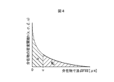
- FIG. 4 is a diagram conceptually illustrating an example of a density function of inclusion dimensions.
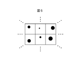
- FIG. 5 is a diagram conceptually illustrating an example of a virtual cell.
- FIG. 6 is a diagram conceptually showing an overview of mechanical parts partitioned by virtual cells.
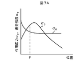
- FIG. 7A is a diagram conceptually illustrating an example of the relationship between the stress amplitude of the acting stress and the stress amplitude of the fatigue strength and the position of the mechanical component when the inclusion size is relatively large.
- FIG. 7A is a diagram conceptually illustrating an example of the relationship between the stress amplitude of the acting stress and the stress amplitude of the fatigue strength and the position of the mechanical component when the inclusion size is relatively large.
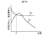
- FIG. 7B is a diagram conceptually illustrating an example of the relationship between the stress amplitude of the acting stress and the stress amplitude of the fatigue strength and the position of the mechanical component when the inclusion size ⁇ area is relatively medium.
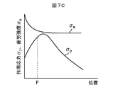
- FIG. 7C is a diagram conceptually illustrating an example of the relationship between the stress amplitude of the acting stress and the stress amplitude of the fatigue strength and the position of the mechanical component when the inclusion size ⁇ area is relatively small.
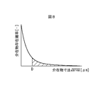
- FIG. 8 is a diagram conceptually illustrating an example of the relationship between the inclusion existence probability and the inclusion size in the virtual cell.
- FIG. 9 is a flowchart for explaining an example of the operation flow of the component fatigue fracture evaluation apparatus.
- FIG. 9 is a flowchart for explaining an example of the operation flow of the component fatigue fracture evaluation apparatus.
- FIG. 10 is a diagram showing the relationship between the distance (depth) from the surface of the wire of the coil spring and the stress amplitude of the residual stress of the coil spring.
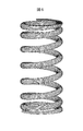
- FIG. 11 is a diagram conceptually showing (part) of the virtual cells set for the coil spring.
- FIG. 12 is a diagram showing the fatigue strength excess probability of the coil springs of materials A and B and the experimental results (500 million fatigue failure probabilities) of each coil spring.
- FIG. 13 is a diagram showing the relationship between the distance (depth) from the surface of the round bar test piece and the stress amplitude of the residual stress of the round bar test piece.
- an inclusion having a dimension equal to or larger than a threshold is obtained by a method such as a slime extraction method in which a certain volume of material is dissolved in an electrolytic solution to extract only inclusions or an acid dissolution method You can measure how much exists.
- the minimum critical dimension of inclusions that can be collected is determined by the roughness of the filter of the apparatus, and not all inclusions can be extracted. Fortunately, internal fatigue failure is not a problem with small inclusions. Therefore, it is effective to evaluate the fatigue of machine parts using only the distribution of large inclusions that contribute to internal fatigue.
- the strength, internal stress, and the like may vary greatly depending on the location, and it is necessary to evaluate fatigue fracture in consideration of these.
- the present inventors quantitatively calculate the probability of exceeding the fatigue strength of a mechanical component when a stress state (average stress or repeated stress) is given as follows. I found a method. By using this method, it is possible to obtain a policy for determining an effective measure for preventing fatigue fracture.
- FIG. 1 is a diagram illustrating an example of a hardware configuration of a component fatigue fracture evaluation apparatus 100.
- the component fatigue fracture evaluation apparatus 100 is for evaluating the fracture performance of mechanical components.
- a component fatigue fracture evaluation apparatus 100 includes a CPU (Central Processing Unit) 101 and a ROM (Read Only). Memory) 102, RAM (Random Access Memory) 103, PD (Pointing Device) 104, HD (Hard Disk) 105, display device 106, speaker 107, communication I / F (Interface) 108, system And a bus 109.
- CPU Central Processing Unit
- ROM Read Only Memory
- RAM Random Access Memory
- PD Pointing Device
- HD Hard Disk
- display device 106 display device
- speaker 107 speaker
- communication I / F (Interface) 108 system And a bus 109.
- the CPU 101 controls the operation of the component fatigue fracture evaluation apparatus 100 in an integrated manner, and controls each component (102 to 108) of the component fatigue fracture evaluation apparatus 100 via the system bus 109.
- the ROM 102 stores a basic input / output system (BIOS) and an operating system program (OS), which are control programs for the CPU 101, programs necessary for the CPU 101 to execute processing described later, and the like.
- BIOS basic input / output system
- OS operating system program
- the RAM 103 functions as a main memory, work area, and the like for the CPU 101.
- the CPU 101 loads various computer programs and the like from the ROM 102 and necessary information from the HD 105 into the RAM 103, and executes various processes by executing the computer programs and the information.
- the PD 104 includes, for example, a mouse, a keyboard, and the like, and constitutes an operation input unit for an operator to input an operation to the component fatigue fracture evaluation apparatus 100 as necessary.
- the HD 105 constitutes storage means for storing various information, data, files, and the like.
- the display device 106 constitutes display means for displaying various information and images based on the control of the CPU 101.
- the speaker 107 constitutes an audio output unit that outputs audio related to various types of information based on the control of the CPU 101.
- the communication I / F 108 communicates various information and the like with an external device via a network based on the control of the CPU 101.
- a system bus 109 is a bus for connecting the CPU 101, ROM 102, RAM 103, PD 104, HD 105, display device 106, speaker 107, and communication I / F 108 so that they can communicate with each other.
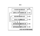
- FIG. 2 is a diagram illustrating an example of a functional configuration of the component fatigue fracture evaluation apparatus 100.
- the component fatigue fracture evaluation apparatus 100 assumes the number of inclusions existing in one machine part such as a spring based on the investigation result of the distribution of inclusions of the material constituting the machine part, Determine the probability that the fatigue strength will be exceeded for the stress state (average stress or repeated stress) where each inclusion is placed, and combine the results to determine the probability of excess fatigue strength for the entire machine part. calculate.
- the number of inclusions existing in one machine part such as a spring based on the investigation result of the distribution of inclusions of the material constituting the machine part.
- the component fatigue fracture evaluation apparatus 100 includes an inclusion distribution quantification unit 201, a virtual cell unit volume deriving unit 202, an estimated fatigue strength deriving unit 203, an acting stress amplitude deriving unit 204, and an excess fatigue strength.
- a probability deriving unit 205 and a fatigue strength excess probability output unit 206 are provided.
- ⁇ Inclusion Distribution Quantification Unit 201 First, measure the size of each inclusion (inclusion size ⁇ area [ ⁇ m]) contained in a sample made of the same type of material as the material constituting the machine part that is the subject of investigation of the fatigue strength excess probability (of the sample) Let the volume be V s [mm 3 ]).
- the inclusion dimension ⁇ area is a so-called “root area”, and is the square root ( ⁇ ) of the projected area (cross-sectional area of the inclusion) when the shape of the inclusion is projected onto a plane. Value.
- root area is a so-called “root area”, and is the square root ( ⁇ ) of the projected area (cross-sectional area of the inclusion) when the shape of the inclusion is projected onto a plane. Value.
- the shape of the inclusion is approximated to a simple figure (shape) such as a rectangle or ellipse, and the projected area of the inclusion (cross-sectional area of the inclusion) is estimated from the representative dimensions of the figure.
- the square root of the area may be the inclusion size ⁇ area.
- a value obtained by simply taking the square root of the product of the major axis and the minor axis, or the square root of the product of the major axis, the minor axis, and ⁇ is taken.
- the value may be an estimated value (inclusion size ⁇ area) of the projected area of the inclusion (cross-sectional area of the inclusion).
- ⁇ X represents X 1/2 (X to the power of 1/2)
- ⁇ area max represents area max 1/2 .
- Such inclusions can be extracted using, for example, a slime method.
- a sample is electrolyzed in a ferrous iron solution, the electrolyzed slime is collected in a mesh-like sampling bag, and residues other than inclusions made of non-ferrous metal are removed by a water tank operation. The residue remaining in the sampling bag is transferred to a magnetic dish and the residue is further removed, followed by sieving and separation.
- the slime method is a known technique as described in Patent Document 2 and the like, detailed description thereof is omitted here.
- the inclusion extraction process is not limited to the slime method.
- the inclusions contained in the sample may be extracted by using other methods such as acid dissolution method and microscopy, and the size of each inclusion ⁇ area may be measured.
- the inclusion distribution quantification unit 201 obtains information on the size of inclusions (inclusion size ⁇ area) extracted by the slime method among inclusions included in the sample, and the operation of the operator and the external device. The data is input and stored based on the communication. In the following description, the information on the inclusion size ⁇ area thus obtained is referred to as “actual measurement data” as necessary.
- the probability distribution of the inclusion size ⁇ area is represented by the conditional probability P of the inclusion whose inclusion size ⁇ area exceeds x.
- the density function p of the inclusion size ⁇ area is approximately expressed by the following formula (1) or (2).
- the distribution function is called differently depending on the value of the coefficient ⁇ , but these are collectively referred to as a density function of a general Pareto distribution.
- ⁇ area follows the general Pareto distribution.
- the inclusion distribution quantification unit 201 derives from the actually measured data the threshold excess inclusion number N u that is the number of inclusions whose inclusion size ⁇ area exceeds the threshold u.
- the inclusion distribution quantifying unit 201 is, for example, an average excess plot obtained by plotting the value of the following equation (3) or a median excess plot obtained by plotting the value of the following equation (4): Based on the threshold value u, the threshold value excess inclusion number N u can be obtained.
- the inclusion distribution quantification unit 201 displays the average excess plot or the median excess plot on the display device 106, determines the threshold u based on the operation of the PD 104 of the operator with respect to this display result, and exceeds the threshold u can be derived intervening the number as a threshold exceeded inclusions number N u.
- i is a variable [ ⁇ ] that specifies an inclusion
- x max is the maximum value [ ⁇ m] of the inclusion dimension ⁇ area included in the measured data.
- the threshold value u of the inclusion dimension ⁇ area does not need to be strictly determined, and the threshold value u of the inclusion dimension ⁇ area can be set to a size that is assumed to contribute to destruction.
- the average excess plot or the median excess plot is displayed on the display device 106, and the threshold value u is input by the operator so that the inclusion distribution quantification unit 201 derives the threshold excess inclusion number N u. I made it. However, this is not always necessary.
- an average excess plot or a median excess plot may be displayed on the display device 106, and the operator may be allowed to input the threshold excess inclusion number Nu .
- the operator himself performs the processing until obtaining the threshold excess inclusion number Nu (without involving the inclusion distribution quantification unit 201), and the inclusion distribution quantification unit 201 includes the threshold u and the threshold excess inclusion.
- the number of objects Nu may be input.
- the threshold u is set after all the inclusion dimensions ⁇ area extracted from each sample are combined. In this case, the threshold for each sample when a u s, it is obvious that a value of the threshold u exceeds the threshold u s.
- the inclusion distribution quantification unit 201 derives the coefficients ⁇ and ⁇ of the general Pareto distribution from the actually measured data.
- the coefficients ⁇ and ⁇ of the general Pareto distribution are derived using the maximum likelihood method.
- the distribution function H (y) of the general Pareto distribution is as shown in the following equation (5).
- the likelihood function L ( ⁇ , ⁇ ) is represented by the product of the density function h (y) represented by the following equation (6), and when the number of samples is n, the following equation (7) is obtained.
- the number of samples n, given threshold exceeded inclusions number N u
- the variable y, (x-u) is given (x is the inclusion size ⁇ area, u is the threshold value).
- the likelihood function L ( ⁇ , ⁇ ) is treated as a log likelihood l ( ⁇ , ⁇ ) expressed by the following equation (8), and the log likelihood l ( ⁇ , ⁇ ) are derived to maximize the coefficients ⁇ , ⁇ .
- the inclusion distribution quantification unit 201 derives the distribution function of the inclusion size ⁇ area and the coefficients ⁇ and ⁇ of the density function as described above.
- the inclusion distribution quantification unit 201 can be realized by using, for example, the CPU 101, the ROM 102, the RAM 103, the PD 104, the HD 105, the display device 106, and the communication I / F 108.
- FIG. 3 is a diagram conceptually showing the virtual unit volume V 0 of the virtual cell. As shown in FIG. 3, the sample volume V s is obtained by multiplying the virtual unit volume V 0 of the virtual cell by the number N 0 of inclusions contained in the sample. The volume V s of the sample is input by an operator's operation.
- FIG. 4 is a diagram conceptually illustrating an example of the density function h (x, ⁇ , ⁇ , u) of the inclusion size ⁇ area.
- the density function h (x, ⁇ , ⁇ , u) of the inclusion size ⁇ area determined from the coefficients ⁇ , ⁇ derived by the inclusion distribution quantifying unit 201, the integration range where the inclusion size ⁇ area is from the threshold u to ⁇ The value integrated with is 1.
- the virtual inclusion ratio ⁇ is in the sample volume V s with respect to the number N u of inclusions whose inclusion size ⁇ area exceeds the threshold u (the number Nu of excess inclusions exceeding the threshold). of inclusion sizes ⁇ area are representative of a ratio of 0 interposing the number exceeds (zero) N 0 (zero excess inclusions number N 0).
- the virtual unit volume V 0 of the virtual cell is expressed as the following equation (10).
- ⁇ is the number of inclusions in the range where the inclusion size ⁇ area is from 0 (zero) to the threshold u.
- FIG. 5 is a diagram conceptually illustrating an example of a virtual cell
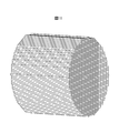
- FIG. 6 is a diagram conceptually illustrating an overview of mechanical parts (springs) partitioned by the virtual cell.
- One rectangular region shown in FIG. 5 is a virtual cell having a virtual unit volume V 0 , and the region of the machine part that is the object of investigation of the fatigue strength excess probability is represented by N Partition with V0 (identical) virtual cells.
- Each virtual cell contains one inclusion whose inclusion dimension ⁇ area exceeds 0 (zero), and the inclusion dimension ⁇ area is distributed according to the density function of the inclusion dimension ⁇ area. To do.
- Virtual cell unit volume deriving portion 202 derives a virtual unit volume V 0 which virtual cells, the N V0 amino virtual cells having a virtual unit volume V 0, the survey fatigue strength excess probability Set for machine parts.
- the number N V0 of virtual cells is expressed by the following equation (11).
- N V0 (V / V s ) ⁇ N u ⁇ ⁇ (11)
- V is the volume [mm 3 ] of the machine part that is the object of investigation of the fatigue strength excess probability, and is input by the operator.
- the virtual cell unit volume deriving unit 202 can be realized by using the CPU 101, the ROM 102, the RAM 103, and the PD 104, for example.
- mm 2 is expressed as a function of inclusion size ⁇ area, Vickers hardness Hv, and stress ratio R [ ⁇ ].
- the stress amplitude ⁇ w of the fatigue strength is expressed as in the following equation (12).
- ⁇ w ⁇ 1.56 ⁇ (Hv + 120) / ( ⁇ area max ) 1/6 ⁇ ⁇ ⁇ (1-R) / 2 ⁇ ⁇ (12)
- the equation (12) is originally an equation for estimating the fatigue limit, but the equation (12) is used as an equation for fatigue strength at about 10 7 times in consideration of the capability of the testing machine at the time of research.
- Hv Vickers hardness.
- R is a stress ratio and is expressed by the following equation (13).
- ⁇ is an influence multiplier of hardness and is expressed by the following equation (14).
- R ( ⁇ m ⁇ w ) / ( ⁇ m + ⁇ w ) (13)
- ⁇ 0.226 + Hv / 10000 (14)
- ⁇ m is the stress amplitude [N / mm 2 ] of the average stress of the machine part.
- the value of the Vickers hardness Hv is obtained from the result of the test of the material constituting the part. Further, the values of the average stress ⁇ m and the stress ratio R of the part are obtained from the load applied to the part and the dimension of the part.
- the stress ratio R the stress ratio of the equivalent stress at each position inside the component or the stress ratio of the main stress in the direction in which the fluctuation of the main stress at each position inside the component is maximized is adopted. To do. Which of these is adopted can be appropriately determined according to the components and the like.
- the inclusion size ⁇ area is determined by the distribution function of the inclusion size ⁇ area determined by the coefficients ⁇ and ⁇ derived by the inclusion distribution quantification unit 201 (see formula (1) or (2)). It is.
- the estimated fatigue strength deriving unit 203 inputs these values based on the operation by the operator, etc., calculates the equation (12), and applies a predetermined number of repeated loads to the machine part.
- the stress amplitude ⁇ w of the fatigue strength in each virtual cell set for the machine part is derived with respect to the stress ratio R in the virtual cell.
- a plurality of such stress amplitudes ⁇ w of fatigue strength are derived by differentiating the inclusion size ⁇ area max and the stress ratio R whose value varies depending on the virtual cell and the stress condition used. .
- the stress amplitude ⁇ w of the fatigue strength can be derived for each virtual cell with respect to the inclusion size ⁇ area max of the inclusion existing inside the machine part.
- the stress amplitude ⁇ w of the fatigue strength is derived from the equation (12).
- the stress amplitude ⁇ w of the fatigue strength is expressed as a function of the inclusion size ⁇ area, the Vickers hardness Hv, and the stress ratio R, it is not necessarily expressed by the equation (12). May be.
- the stress amplitude ⁇ w of the fatigue strength may be expressed by the following equation (15).
- ⁇ w ⁇ 1.56 ⁇ (Hv + 120) / ( ⁇ area max ) 1/6 ⁇ ⁇ 0.5 ⁇ ⁇ m (15)
- the stress amplitude ⁇ w of the fatigue strength is expressed not by the stress ratio R but by using the stress amplitude ⁇ m of the average stress of the part.
- the stress amplitude ⁇ m of the average stress of the component can be expressed by using the stress amplitude ⁇ w of the fatigue strength and the stress ratio R, so that the equation (15) is expressed by the stress ratio R Is equivalent to
- the coefficients shown in the equations (12) and (15) can be changed.
- the Vickers hardness Hv shown in the equations (12) and (15) has a correlation with the strength [N / mm 2 ] of the material of the part. Therefore, instead of the Vickers hardness Hv, the stress amplitude ⁇ w of the fatigue strength may be expressed using the strength of the material of the component.
- the formulas (12) and (15) are general formulas related to steel materials, the fatigue characteristics of the material to be evaluated are corrected by modifying these formulas and using the stress ratio, hardness, and inclusion dimensions as parameters. If a function tailored to is created and used, higher accuracy can be achieved.
- the estimated fatigue strength deriving unit 203 can be realized by using, for example, the CPU 101, the ROM 102, the RAM 103, the PD 104, and the HD 105.
- the applied stress amplitude deriving unit 204 applies a repeated load to a machine part under a load condition P set in advance by an operator, and the applied stress stress amplitude ⁇ acting on each virtual cell set for the machine part. p is derived.
- stress amplitude ⁇ p of acting stress acting on each virtual cell set for the machine part when a repeated load is applied to the machine part under the load condition P set in advance by the operator. “as needed, referred to as” stress amplitude sigma p of the working stress acting on each virtual cell of the mechanical parts "or” stress amplitude sigma p of the working stress ".
- the load condition P indicates what kind of repeated load is applied to the machine part.
- the acting stress amplitude deriving unit 204 inputs information on the machine part such as the shape of the machine part, the load condition P, and the strength of the material constituting the machine part (for example, tensile strength, yield stress, and work hardening characteristics).
- the applied stress amplitude deriving unit 204 acquires information on these mechanical parts based on an operator's operation, communication with an external device, or the like.
- the applied stress amplitude deriving unit 204 uses the acquired information on the machine part, and each stress in each virtual cell of the machine part when a repeated load is applied to the machine part under the load condition P set in advance by the operator. Derive component changes.
- the change of each stress component in each virtual cell of the machine part is, for example, FEM (Finite Element Method) or BEM (Boundary element).
- the method can be derived by performing an analysis using a method) or performing a calculation using a method based on material mechanics.
- heat treatment, plastic working, shot peening treatment, and the like are performed on the machine part, and internal stress may be generated in the machine part even in an unloaded state (a state where no load is applied).
- This internal stress can be measured, for example, by a method of alternately performing residual stress measurement by X-rays and electrolytic polishing.
- the internal stress in this unloaded state is added to the change of each stress component in each virtual cell of the machine part when a load is repeatedly applied under the load condition P set in advance by the operator using a method based on material mechanics. By combining them, it is possible to design a fatigue considering the internal stress in the no-load state.
- the working stress amplitude deriving unit 204 determines, as, for example, each virtual cell of the mechanical part as the stress amplitude ⁇ p of the working stress from the change of each stress component in each virtual cell of the mechanical part derived as described above.
- the amplitude of the corresponding stress or the amplitude of the main stress in the direction in which the fluctuation of the main stress in each virtual cell of the machine part is maximized is employed. Which of these is adopted can be appropriately determined according to the machine part and the like.
- a plurality of such stress amplitudes ⁇ p of the applied stress are derived with different virtual cells set for the machine part.
- the stress amplitude ⁇ p of the acting stress can be derived for each virtual cell set for the machine part.
- the equivalent stress based on the maximum value of the load amplitude applied to the machine part is also defined as the stress amplitude ⁇ p of the applied stress that is 1/2 of the equivalent stress based on the value obtained by subtracting the minimum value from the maximum value of the load amplitude applied to the machine component.
- the stress amplitude ⁇ p of the applied stress may be 1 ⁇ 2 of the value obtained by subtracting the equivalent stress based on the minimum value of the load amplitude.
- the applied stress amplitude deriving unit 204 can be realized by using the CPU 101, the ROM 102, the RAM 103, the PD 104, and the HD 105, for example.
- the fatigue strength determination function f ( ⁇ p , ⁇ w ) shown in the equation (16) is set for each virtual cell, and the stress amplitude ⁇ p of the acting stress of the virtual cell is the fatigue strength of the virtual cell.
- the value is 1 when the value of the stress amplitude ⁇ w exceeds 1 and 0 (zero) otherwise.
- the stress amplitude ⁇ w of the fatigue strength of the virtual cell is obtained for each inclusion size ⁇ area. Therefore, for one virtual cell, the value of the fatigue strength determination function f ( ⁇ p , ⁇ w ) is obtained for each inclusion size ⁇ area.
- FIG. 7 is a diagram conceptually illustrating an example of the relationship between the stress amplitude ⁇ p of the acting stress and the stress amplitude ⁇ w of the fatigue strength, and the position of the mechanical component.
- 7A shows the relationship when the inclusion size ⁇ area is relatively large
- FIG. 7B shows the relationship when the inclusion size ⁇ area is relatively medium
- FIG. 7C shows the inclusion size ⁇ The relationship when the area is relatively small is shown.
- the value of the fatigue strength determination function f ( ⁇ p , ⁇ w ) is 0 (zero).
- the stress amplitude ⁇ p of the acting stress of the virtual cell is determined as fatigue of the virtual cell.
- the inclusion sizes ⁇ area made to exceed the stress amplitude sigma w strength can be obtained in each virtual cell.
- the stress amplitude ⁇ p of the acting stress of the virtual cell exceeds the value of the stress amplitude ⁇ w of the fatigue strength of the virtual cell.
- the fatigue strength excess probability deriving unit 205 derives the fatigue strength excess probability pfV of the machine part as an index for determining fatigue failure of the machine part.
- This fatigue strength excess probability is a value indicating the probability that an acting stress acting on a mechanical part such as a spring will exceed the fatigue strength under repeated load conditions with a gigacycle order.
- the stress state around a certain inclusion is not affected by the stress distribution caused by neighboring inclusions, and as described above, the dimensions are not known. However, it is assumed that a plurality of virtual cells having a virtual unit volume V 0 containing one inclusion are collected to form a machine part.
- the fact that a mechanical part undergoes fatigue failure is defined as that one of these virtual cells undergoes fatigue failure. Then, a value obtained by subtracting from 1 the probability that all virtual cells do not undergo fatigue failure was derived as the fatigue strength excess probability pfV of the machine part.
- the fatigue strength excess probability p V0 in a virtual cell of a certain virtual unit volume V 0 is expressed by the following equation (17).
- h (x, ⁇ , ⁇ , u) / ⁇ is “inclusion in virtual cell” obtained by dividing density function of inclusion size ⁇ area by virtual inclusion ratio.
- Existence probability which is expressed by the following equations (18) and (19), respectively.
- FIG. 8 is a diagram conceptually illustrating an example of the relationship between the inclusion existence probability and the inclusion size ⁇ area in the virtual cell.
- the area of the hatched area shown in FIG. 8 represents the fatigue strength excess probability pV0 in one virtual cell.
- D in FIG. 8 is an inclusion dimension ⁇ area where the stress amplitude ⁇ p of the acting stress of the virtual cell exceeds the stress amplitude ⁇ w of the fatigue strength of the virtual cell, and the fatigue strength shown in FIG. This corresponds to the inclusion size ⁇ area when the stress amplitude ⁇ w is obtained.
- the probability of exceeding the fatigue strength in the entire machine part that is, the fatigue strength excess probability pfV of the entire machine part composed of all virtual cells is expressed by the following equation (20).
- i is a variable [ ⁇ ] that identifies the virtual cell.
- the fatigue strength excess probability pfV of a mechanical part is a value obtained by subtracting the probability that all virtual cells will not undergo fatigue failure from 1 (see the right side of equation (20)).
- the fatigue strength excess probability deriving unit 205 derives the fatigue strength excess probability pfV of the entire machine part as described above.
- the fatigue strength excess probability deriving unit 205 can be realized by using, for example, the CPU 101, the ROM 102, and the RAM 103.
- the fatigue strength excess probability output unit 206 displays the value of the fatigue strength excess probability pfV of the entire mechanical component derived by the fatigue strength excess probability derivation unit 205 on a display device based on an instruction from an operator, Or stored in a storage medium.
- a method of using the fatigue strength excess probability pfV of the entire machine part for example, design of the machine part so that the fatigue strength excess probability pfV of the entire machine part becomes a predetermined value (external force as a use condition, shape of the machine part) The material constituting the machine part is determined), and the machine part can be manufactured according to the design.
- the fatigue strength excess probability output unit 206 can be realized by using, for example, the CPU 101, the ROM 102, the RAM 103, the PD 104, the HD 105, the display device 106, and the communication I / F 108.
- step S1 the inclusion distribution quantification unit 201 performs actual measurement data acquisition processing. Specifically, the inclusion distribution quantification unit 201 acquires information on the inclusion size ⁇ area of the sample (made of the same kind of material as the machine part) obtained by the slime method or the like as performance data.
- step S ⁇ b> 2 the inclusion distribution quantification unit 201 performs a threshold excess inclusion number derivation process. Specifically, the inclusion distribution quantification unit 201 creates and displays an average excess plot or a median excess plot using the result data obtained in step S1.
- the inclusion distribution quantification unit 201 inputs a threshold u visually determined by the operator based on the average excess plot or the median excess plot, and from the actual data, the number of inclusions exceeding the threshold u is included. derived as object number N u.
- step S3 the inclusion distribution quantification unit 201 performs a general Pareto distribution coefficient derivation process. Specifically, the inclusion distribution quantification unit 201 calculates the log likelihood l ( ⁇ , ⁇ ) of the equation (8) based on the actual data obtained in step S1 and the threshold u derived in step S2. The maximum coefficients ⁇ and ⁇ are derived.
- step S4 the virtual cell unit volume deriving unit 202 performs a virtual inclusion ratio deriving process. Specifically, the virtual cell unit volume deriving unit 202 calculates the equation (9) based on the threshold value u derived in step S2 and the coefficients ⁇ and ⁇ derived in step S3, and calculates the virtual inclusion ratio. Derived ⁇ .
- step S5 the virtual cell unit volume deriving unit 202 performs a virtual unit volume deriving process. Specifically virtual cell unit volume deriving unit 202 receives the volume V s of the sample, and the volume V s of the sample, and the over-threshold inclusions number N u derived in step S2, derived in step S4 Based on the virtual inclusion ratio ⁇ , the calculation of equation (10) is performed to derive the virtual unit volume V 0 of the virtual cell.
- the virtual cell unit volume deriving unit 202 receives the volume V of the machine parts, and the volume V of the machine parts, and volume V s of the sample, a threshold excess inclusions number N u derived in step S2, Based on the virtual inclusion ratio ⁇ derived in step S4, the calculation of equation (11) is performed to derive the number N V0 of virtual cells. Then, the virtual cell unit volume deriving unit 202 sets a virtual cell for the machine part (that is, divides the region of the machine part by N V0 virtual cells having the virtual unit volume V 0 ).
- step S6 the applied stress amplitude deriving unit 204 performs an applied stress derivation process. Specifically, the acting stress amplitude deriving unit 204 acquires information on the machine part, and uses the acquired information on the machine part to apply each load when a load is repeatedly applied to the machine part under the load condition P set in advance by the operator. The change of each stress component in the virtual cell is derived. Then, the applied stress amplitude deriving unit 204 acts on the mechanical component when a repeated load is applied to the mechanical component under the load condition P set in advance by the operator from the change of each stress component in the derived virtual cell. The stress amplitude ⁇ p of the applied stress is derived for each virtual cell.
- the estimated fatigue strength deriving unit 203 performs fatigue strength deriving processing. Specifically, the estimated fatigue strength deriving unit 203 inputs values of the Vickers hardness Hv, the average stress ⁇ m of the machine part, and the stress ratio R. The estimated fatigue strength deriving unit 203 then distributes the inclusion size ⁇ area determined by the Vickers hardness Hv, the average stress ⁇ m of the machine part, and the stress ratio R, and the coefficients ⁇ and ⁇ derived in step S3. (12) is calculated based on the inclusion size ⁇ area obtained based on.
- a predetermined load is repeatedly applied to the machine part, and the stress amplitude ⁇ w of the fatigue strength corresponding to the fatigue limit where the number of repetitions is approximately 10 7 times or more becomes the inclusion size ⁇ area For each virtual cell.
- step S8 the fatigue strength excess probability deriving unit 205 performs a fatigue strength determination function derivation process. Specifically, the fatigue strength excess probability deriving unit 205 calculates “the stress amplitude ⁇ w of fatigue strength for each inclusion cell ⁇ area and each virtual cell” derived in step S7 and “every virtual cell for each virtual cell” derived in step S6.
- the fatigue strength determination function f ( ⁇ p , ⁇ w ) is derived based on the calculation of the equation (16) based on the stress amplitude ⁇ p of the applied stress.
- step S9 the fatigue strength excess probability deriving unit 205 performs virtual cell fatigue strength excess probability derivation processing.
- the fatigue strength excess probability deriving unit 205 includes the threshold value u derived in step S2, the coefficients ⁇ and ⁇ derived in step S3, and the fatigue strength determination function f ( ⁇ p , ⁇ derived in step S8. w )), the integration is performed in the inclusion size range from 0 to infinity using the equation (17), and the fatigue strength excess probability pV0 in each virtual cell is derived.
- step S10 the fatigue strength excess probability deriving unit 205 performs a total fatigue strength excess probability derivation process. Specifically, the fatigue strength excess probability deriving unit 205 calculates the equation (20) based on the fatigue strength excess probability p V0 in each virtual cell derived in step S9, and makes a machine comprising all virtual cells. The fatigue strength excess probability pfV of the entire part is derived.
- step S11 the fatigue strength excess probability output unit 206 performs total fatigue strength excess probability output processing. Specifically, the fatigue strength excess probability output unit 206 displays the fatigue strength excess probability pfV of the entire machine part derived in step S10 on the display device based on an instruction from the operator, or transmits it to an external device. Or store it on a storage medium.
- the virtual unit volume V 0 obtained by equally dividing the region of the machine part so as to include one inclusion is obtained.
- the probability that the stress amplitude ⁇ p of the applied stress exceeds the stress amplitude ⁇ w of the fatigue strength (the virtual cell fatigue strength excess probability p V0 ) is derived.
- the probability that the stress amplitude ⁇ p of the applied stress exceeds the stress amplitude ⁇ w of the fatigue strength in at least one virtual cell is calculated .
- This method can be applied to a wide range of applications, for example, inclusion control, hardness control, residual stress control, shape stress, and examination of design stress based on usage conditions to satisfy the fatigue performance and fracture probability of target machine parts. It is considered possible. Furthermore, this method can clarify how much each parameter has an influence on other parameters, and can uniformly express the effects of parameters that have been studied separately. Therefore, this method can be an effective tool for fatigue design of machine parts. This method can also be applied to the evaluation of materials having different hardness depending on the part and the evaluation considering the difference in the influence of inclusion species on the fatigue strength. Furthermore, this method can be applied to various machine parts such as a coil spring.
- the stress distribution of one virtual cell needs to be substantially uniform.
- the virtual unit volume V 0 may increase with respect to the stress distribution.
- the sub virtual cell setting process for setting the sub virtual cell by equally dividing the virtual unit volume V 0 into a plurality of parts can be performed in at least one of the virtual cells.
- the fatigue strength excess probability p Dj in the sub-virtual cell is expressed by the following equation (21).
- V Dj is the volume of the sub virtual cell
- ⁇ pi, j is the stress amplitude of the acting stress acting on each sub virtual cell.
- N D the number of sub-virtual cells
- the fatigue strength excess probability p V0 in the virtual cell is derived by the following equation (22)
- the fatigue strength excess probability p fV of the machine part is expressed by the following (23) It is derived by the formula.
- the fatigue strength excess probability p V0 in the virtual cell is obtained by integrating the fatigue strength excess probabilities p Dj in the sub virtual cells shown in the equation (21).
- the fatigue strength excess probability pfV of the machine part is obtained by subtracting from 1 the probability that all virtual cells will not undergo fatigue failure.
- the distribution function of the inclusion size ⁇ area is a Pareto distribution or a beta distribution is shown.
- the density function h (x, ⁇ , ⁇ , u) of the inclusion size ⁇ area in the equations (21) to (23) is the density function h (x, ⁇ , u)
- the inclusion size ⁇ area This can also be applied when the distribution function of is an exponential distribution. As described above, even if the number of inclusions is small or there is a steep stress gradient inside the mechanical component, the fatigue strength excess probability pfV of the entire mechanical component can be appropriately derived. .
- Example 1 a coil spring having a compressive residual stress introduced on the surface thereof is used as a machine part.
- the material A is a material collected from a site where the density of inclusions is (relatively) high
- the material B is a material collected from a position where the density of inclusions is (relatively) low.
- FIG. 10 is a diagram showing the relationship between the distance (depth) from the surface of the wire of the coil spring and the stress amplitude of the residual stress of the coil spring.
- the residual stress shown in FIG. 10 is introduced into the coil spring.
- material A having a volume of 2500 [mm 3 ]
- the iron portion was melted and only the inclusions were extracted.
- 100 inclusions with an inclusion size ⁇ area of 20 [ ⁇ m] or more were extracted from the material A.
- the material B having a volume of 7500 [mm 3 ] the iron portion was melted and only the inclusions were extracted using the slime extraction method.
- the number was 100.
- the fatigue strength excess probability pfV of the entire coil spring was predicted. From the distribution function of the inclusion size ⁇ area of the materials A and B, 0.733 [mm 3 ] as the virtual unit volume V 0A of the material A and 2.1 [mm 3 ] as the virtual unit volume V 0B of the material B, respectively. Obtained.
- the coil spring of material A was partitioned with 3409 virtual cells, the same as the number of inclusions assumed to be present in the coil spring to be evaluated.
- the coil spring of the material B since the density of the inclusion is 1/3 of the material A, the coil spring can be defined by 1/3 the number of virtual cells of the material A.
- the size of the virtual cell is too large, and a large stress distribution is generated in one virtual cell. From this, for the coil spring of material B, the coil spring was partitioned by sub-virtual cells obtained by dividing one virtual cell into three.
- FIG. 11 is a diagram conceptually showing (part) of the virtual cells set for the coil spring.
- Coil springs wound at an equal pitch are in a uniform stress state in the length direction of the strands. For this reason, the length direction of the strand was not partitioned by virtual cells.
- the cross section of the strand was finely divided so that the stress at the position can be reproduced in each virtual cell. Since 3409 virtual cells are used for the coil spring of material A, the coil spring of material A is partitioned by 3409 virtual cells that are in the form of a spring.
- the stress distribution of each of these virtual cells and sub-virtual cells is uniform.
- the inclusion existence probability in the sub virtual cell is 1/3 times the inclusion existence probability in the virtual cell.
- Murakami's equation is an equation for estimating the fatigue limit, it has been found from the experimental results of the present inventors that it corresponds to a fatigue strength of about 10 8 to 10 10 times. It has also been confirmed that the change in fatigue strength after 10 8 to 10 10 times is extremely small and is several percent or less.
- the stress used for fatigue evaluation was the stress ratio and amplitude of the maximum principal stress.
- the state of stress distribution inside the coil spring is the stress that can be estimated by the coil spring whirl theory as the fluctuating stress generated inside the coil spring under repeated load, the residual stress due to shot peening as the static stress, and the length of the coil spring.
- the torsional stress corresponding to the load necessary to fix the thickness can be added up and calculated.
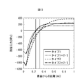
- FIG. 12 is a diagram showing the fatigue strength excess probability pfV of the entire coil springs of materials A and B estimated under the above conditions, and the experimental results (probability of fatigue failure of 500 million times) of each coil spring.
- the solid line is the fatigue strength excess probability pfV of the entire coil spring of material A
- the white circle is the experimental result (500 million fatigue failure probability) of the coil spring of material A.
- the broken line is the fatigue strength excess probability pfV of the entire coil spring of material B
- the black circle is the experimental result (probability of fatigue failure of 500 million times) of the coil spring of material B.
- FIG. 12 it can be seen that the fatigue strength excess probability pfV of the whole coil spring and the experimental result are in good agreement.
- Example 2 Next, Example 2 will be described. In the present embodiment, a description will be given of a case where a rotating bending test is performed in which a tensile moment and a compressive force are repeatedly applied to the surface while a bending moment is applied.
- a round bar test piece in which compressive residual stress was introduced into the surface by shot peening was used as a machine part.
- FIG. 13 is a graph showing the relationship between the distance (depth) from the surface of the round bar test piece and the stress amplitude of the residual stress of the round bar test piece.
- the residual stress near the surface layer of the round bar test piece was measured, and the residual stress pattern inside the round bar test piece was determined from the measured residual stress near the surface layer.
- the residual stress patterns are five patterns in which the magnitude and depth distribution of the residual stress are changed, and one of them is assumed to have no residual stress.
- the iron part was melt
- 100 inclusions having an inclusion size ⁇ area of 20 [ ⁇ m] or more were extracted.
- a distribution function of inclusion size ⁇ area an approximate function was obtained by a maximum likelihood method using a beta distribution of general Pareto distribution as an extreme value statistical function.
- the test stress stress amplitude on the surface of the test piece
- the embodiment of the present invention described above can be realized by a computer executing a program. Further, a computer-readable recording medium in which the program is recorded and a computer program product such as the program can also be applied as an embodiment of the present invention.
- the recording medium for example, a flexible disk, a hard disk, an optical disk, a magneto-optical disk, a CD-ROM, a magnetic tape, a nonvolatile memory card, a ROM, or the like can be used.
- the embodiments of the present invention described above are merely examples of implementation in carrying out the present invention, and the technical scope of the present invention should not be construed as being limited thereto. Is. That is, the present invention can be implemented in various forms without departing from the technical idea or the main features thereof.
- the present invention can be used, for example, for designing and manufacturing machine parts and estimating the cause of destruction of machine parts.
Abstract
Description
しかしながら、ショットピーニングやせん断応力の影響等、複雑な応力分布を持つばね等の機械部品としての破壊性能を評価する有効な方法はこれまでになかった。よって、既存の材料の実績に基づく疲労設計線図等を基に疲労設計されているのが現状である。 In mechanical parts of high-strength steel subjected to high-cycle loads, it is necessary to reduce the risk of component breakage due to internal fatigue failure starting from internal defects such as inclusions. In internal fatigue fracture, the size of inclusions that are the starting point and the existence probability of inclusions at high stress sites are considered to have a significant effect. Conventionally, a method for predicting the fatigue limit starting from inclusions has been formulated, and the fatigue limit based on such an estimation formula can be predicted under uniform stress (see Non-Patent Document 1).
However, there has been no effective method for evaluating the fracture performance as a mechanical part such as a spring having a complicated stress distribution such as the influence of shot peening or shear stress. Therefore, the present situation is that the fatigue design is based on the fatigue design diagram based on the results of the existing materials.
また、特許文献1に記載の技術により、素材の疲労強度のばらつきを求めるためには、多数の疲労試験を行ってP-S-N曲線を作成し、材料の疲労強度に関するワイブルプロットを作成する必要がある。また、特許文献1に記載の技術では、機械部品の位置ごとの材料特性(介在物の分布)の差を(素材の疲労強度のばらつきとは別に)考慮することができなかった。 In the technique described in Non-Patent Document 1, the fatigue fracture phenomenon is obtained under uniform stress by formulating the fatigue strength of mechanical parts and formulating the maximum inclusion size and maximum inclusion distribution by extreme value statistical processing. It is possible to perform fatigue design of machine parts in consideration of the volume effect that affects them. However, in the technique described in Non-Patent Document 1, the fatigue design of a machine part is performed in consideration of both the volume effect (inclusion size and density distribution) and the stress distribution inside the machine part. I can't.
Moreover, in order to obtain | require the dispersion | variation in the fatigue strength of a raw material with the technique of patent document 1, it is necessary to perform many fatigue tests, to produce a PSN curve, and to make the Weibull plot regarding the fatigue strength of a material. Further, the technique described in Patent Document 1 cannot take into account a difference in material characteristics (inclusion distribution) for each position of mechanical parts (aside from variations in the fatigue strength of materials).
高張力鋼の内部に含まれる介在物を起点とする内部疲労破壊については、いわゆる疲労限がみられず、長寿命域でも疲労強度が徐々に低下することが知られている。しかしながら、その傾きは極めて小さく、本発明者らは、同じ程度の寸法の介在物でも寿命が1000倍以上異なることを実験的にも確認している。つまり、こうした材料の疲労設計は寿命ではなく、疲労強度で設計することが合理的であることを示している(非特許文献2を参照)。 Before describing embodiments of the present invention, the background leading to the embodiments of the present invention will be described.
As for internal fatigue fracture starting from inclusions contained in the inside of high-tensile steel, it is known that the so-called fatigue limit is not observed, and the fatigue strength gradually decreases even in a long life region. However, the inclination is extremely small, and the present inventors have experimentally confirmed that the lifespan of inclusions having the same size is 1000 times or more different. That is, it is shown that it is reasonable to design such materials with fatigue strength rather than life (see Non-Patent Document 2).
近年は、内部疲労破壊を防止するために、高張力鋼の内部に存在する介在物の大きさや数が小さくなっている。したがって、こうした材料の内部の介在物を検出することは難しい。しかしながら、ある程度の体積の材料を電解液中で溶かして介在物だけを抽出するスライム抽出法や、酸溶解法等の方法で、ある材料の所定の体積中に閾値以上の寸法を有する介在物がどの程度存在するかを測定できる。ただし、これらの手法では、採取できる介在物の最小限界寸法は装置のフィルターの粗さで決まり、全ての介在物を抽出できるわけではない。幸いにして、小さい介在物からは内部疲労破壊が問題にならない。そこで、内部疲労に寄与するような大きな介在物の分布だけを用いて、機械部品の疲労を評価することが有効である。
また、表層や内部での処理過程が異なるために、場所によって強度や内部応力等が大きく変わる可能性もあり、これら考慮して疲労破壊を評価することが必要である。 In addition, when a high stress amplitude that causes internal fatigue is applied to a high-strength steel, the stress intensity factor rapidly increases once a crack is generated. For this reason, in high-strength steel, the crack growth rate is fast, and the crack grows rapidly and causes fatigue failure. Therefore, when a machine part having a small cross section such as a spring is made of high-tensile steel, the fracture life of the machine part is mostly governed by the fatigue crack generation life.
In recent years, in order to prevent internal fatigue failure, the size and number of inclusions present in high-strength steel have been reduced. Therefore, it is difficult to detect inclusions inside such materials. However, in a certain volume of a certain material, an inclusion having a dimension equal to or larger than a threshold is obtained by a method such as a slime extraction method in which a certain volume of material is dissolved in an electrolytic solution to extract only inclusions or an acid dissolution method You can measure how much exists. However, in these methods, the minimum critical dimension of inclusions that can be collected is determined by the roughness of the filter of the apparatus, and not all inclusions can be extracted. Fortunately, internal fatigue failure is not a problem with small inclusions. Therefore, it is effective to evaluate the fatigue of machine parts using only the distribution of large inclusions that contribute to internal fatigue.
In addition, since the treatment process on the surface layer and inside is different, the strength, internal stress, and the like may vary greatly depending on the location, and it is necessary to evaluate fatigue fracture in consideration of these.
<部品(機械部品)の疲労破壊評価装置のハードウェア構成>
図1は、部品の疲労破壊評価装置100のハードウェア構成の一例を示す図である。部品の疲労破壊評価装置100は、機械部品の破壊性能を評価するためのものである。
図1に示すように、部品の疲労破壊評価装置100は、CPU(Central Processing Unit)101と、ROM(Read Only
Memory)102と、RAM(Random Access Memory)103と、PD(Pointing Device)104と、HD(Hard Disk)105と、表示装置106と、スピーカ107と、通信I/F(Interface)108と、システムバス109とを有している。 Hereinafter, an embodiment of the present invention will be described with reference to the drawings.
<Hardware configuration of fatigue failure evaluation equipment for parts (mechanical parts)>
FIG. 1 is a diagram illustrating an example of a hardware configuration of a component fatigue
As shown in FIG. 1, a component fatigue
Memory) 102, RAM (Random Access Memory) 103, PD (Pointing Device) 104, HD (Hard Disk) 105,
ROM102は、CPU101の制御プログラムであるBIOS(Basic Input/Output System)やオペレーティングシステムプログラム(OS)、CPU101が後述する処理を実行するために必要なプログラム等を記憶する。 The
The
PD104は、例えば、マウスやキーボード等からなり、操作者が必要に応じて、部品の疲労破壊評価装置100に対して操作入力を行うための操作入力手段を構成する。
HD105は、各種の情報やデータ、ファイル等を記憶する記憶手段を構成する。
表示装置106は、CPU101の制御に基づいて、各種の情報や画像を表示する表示手段を構成する。
スピーカ107は、CPU101の制御に基づいて、各種の情報に係る音声を出力する音声出力手段を構成する。 The
The
The
The
The
システムバス109は、CPU101、ROM102、RAM103、PD104、HD105、表示装置106、スピーカ107及び通信I/F108を相互に通信可能に接続するためのバスである。 The communication I /
A
図2は、部品の疲労破壊評価装置100の機能的な構成の一例を示す図である。本実施形態の部品の疲労破壊評価装置100は、機械部品を構成する材料の介在物の分布の調査結果をもとに、ばね等の一つの機械部品に存在する介在物の個数を想定し、その介在物の一つずつがおかれる応力状態(平均応力や繰り返し応力)に対して疲労強度を超えるかどうかの確率を判定し、その結果を総合して機械部品全体としての疲労強度超過確率を計算する。
図2において、部品の疲労破壊評価装置100は、介在物分布定量化部201と、仮想セル単位体積導出部202と、推定疲労強度導出部203と、作用応力振幅導出部204と、疲労強度超過確率導出部205と、疲労強度超過確率出力部206とを有する。 <Fatigue fracture evaluation equipment for parts>
FIG. 2 is a diagram illustrating an example of a functional configuration of the component fatigue
In FIG. 2, the component fatigue
まず、疲労強度超過確率の調査対象となる機械部品を構成する材料と同じ種類の材料からなるサンプルに含まれるそれぞれの介在物の寸法(介在物寸法√area[μm])を測定する(サンプルの体積をVs[mm3]とする)。ここで、介在物寸法√areaは、所謂「ルートエリア」と称されるものであり、介在物の形状を平面に投影した場合の投影面積(介在物の断面積)の平方根(√)をとった値である。しかしながら、現実的にはこのような面積を正確に求めることは困難であるため、必ずしもこのようにする必要はない。例えば、介在物の形状を四角形や楕円形等の簡単な図形(形状)に近似させてその図形の代表的な寸法から介在物の投影面積(介在物の断面積)を推定して求め、この面積の平方根を介在物寸法√areaとしても良い。具体例として、介在物の形状を楕円形に近似した場合には、簡易的にその長径と短径との積の平方根をとった値や長径と短径とπとの積の平方根をとった値を介在物の投影面積(介在物の断面積)の推定値(介在物寸法√area)としてもよい。
尚、本明細書において、√Xとは、X1/2(Xの1/2乗)を示し、例えば、√areamaxはareamax 1/2を示す。 <Inclusion
First, measure the size of each inclusion (inclusion size √area [μm]) contained in a sample made of the same type of material as the material constituting the machine part that is the subject of investigation of the fatigue strength excess probability (of the sample) Let the volume be V s [mm 3 ]). Here, the inclusion dimension √area is a so-called “root area”, and is the square root (√) of the projected area (cross-sectional area of the inclusion) when the shape of the inclusion is projected onto a plane. Value. However, in reality, it is difficult to accurately obtain such an area, and thus it is not always necessary to do so. For example, the shape of the inclusion is approximated to a simple figure (shape) such as a rectangle or ellipse, and the projected area of the inclusion (cross-sectional area of the inclusion) is estimated from the representative dimensions of the figure. The square root of the area may be the inclusion size √area. As a specific example, when the shape of the inclusion is approximated to an ellipse, a value obtained by simply taking the square root of the product of the major axis and the minor axis, or the square root of the product of the major axis, the minor axis, and π is taken. The value may be an estimated value (inclusion size √area) of the projected area of the inclusion (cross-sectional area of the inclusion).
In the present specification, √X represents X 1/2 (X to the power of 1/2), and for example, √area max represents area max 1/2 .
尚、スライム法は、特許文献2等に記載されているように公知の技術であるので、ここでは、その詳細な説明を省略する。また、ここでは、スライム法を用いて介在物の数を測定する場合を例に挙げて説明した。しかしながら、介在物抽出処理は、スライム法によるものに限定されない。例えば、酸溶解法や顕微鏡法等のその他の手法を用いて、サンプルに含まれる介在物を抽出してそれぞれの介在物寸法√areaを測定してもよい。 Such inclusions can be extracted using, for example, a slime method. In the slime method, a sample is electrolyzed in a ferrous iron solution, the electrolyzed slime is collected in a mesh-like sampling bag, and residues other than inclusions made of non-ferrous metal are removed by a water tank operation. The residue remaining in the sampling bag is transferred to a magnetic dish and the residue is further removed, followed by sieving and separation.
Since the slime method is a known technique as described in Patent Document 2 and the like, detailed description thereof is omitted here. Here, the case where the number of inclusions is measured using the slime method has been described as an example. However, the inclusion extraction process is not limited to the slime method. For example, the inclusions contained in the sample may be extracted by using other methods such as acid dissolution method and microscopy, and the size of each inclusion √area may be measured.
本実施形態では、介在物寸法√areaが閾値uを超える介在物のうち、介在物寸法√areaがxを超える介在物の条件付き確率Pで介在物寸法√areaの確率分布が表されるものとする。そうすると、介在物寸法√areaの密度関数pは、近似的に以下の(1)式又は(2)式で表される。
p(x)={1+ξ(x-u)/σ}-1/ξ-1 ・・・(1)
ただし、1+ξ(x-u)/σ>0,ξ≠0
p(x)=exp(-(x-u)/σ) ・・・(2)
ただし、ξ=0の場合の特異解(指数分布)
(1)式において、ξ、σは係数[-]、uは介在物寸法の閾値[μm]、x=x1,x2,・・・,xNuは閾値u以上の介在物の寸法(介在物寸法√area)[μm]である。
ここで、ξ>0の場合(1)式はパレート分布の密度関数となり、ξ<0の場合(1)式はベータ分布の密度関数となる。また、(2)式は指数分布である。このように係数ξの値によって分布関数の呼び方は変わるが、これらは、一般パレート分布の密度関数と総称される。このように、本実施形態では、介在物寸法√areaの分布関数が一般パレート分布に従うものとする。 The inclusion
In this embodiment, among the inclusions whose inclusion size √area exceeds the threshold u, the probability distribution of the inclusion size √area is represented by the conditional probability P of the inclusion whose inclusion size √area exceeds x. And Then, the density function p of the inclusion size √area is approximately expressed by the following formula (1) or (2).
p (x) = {1 + ξ (x−u) / σ} −1 / ξ−1 (1)
However, 1 + ξ (x−u) / σ> 0,
p (x) = exp (− (x−u) / σ) (2)
However, singular solution when ξ = 0 (exponential distribution)
In equation (1), ξ and σ are coefficients [−], u is a threshold value of inclusion size [μm], x = x 1 , x 2 ,. Inclusion size √area) [μm].
Here, when ξ> 0, the expression (1) is a Pareto distribution density function, and when ξ <0, the expression (1) is a beta distribution density function. Moreover, (2) Formula is exponential distribution. In this way, the distribution function is called differently depending on the value of the coefficient ξ, but these are collectively referred to as a density function of a general Pareto distribution. Thus, in this embodiment, it is assumed that the distribution function of the inclusion size √area follows the general Pareto distribution.
ここで、介在物寸法√areaの閾値uについては、厳密に定める必要は無く、破壊に寄与すると想定される程度の大きさを介在物寸法√areaの閾値uを定めることができる。
尚、本実施形態では、平均超過プロット又はメジアン超過プロットを表示装置106に表示して、オペレータに閾値uを入力させて介在物分布定量化部201が閾値超過介在物数Nuを導出するようにした。しかしながら、必ずしもこのようにする必要はない。例えば、平均超過プロット又はメジアン超過プロットを表示装置106に表示して、オペレータに閾値超過介在物数Nuを入力させるようにしてもよい。また、閾値超過介在物数Nuを得るまでの処理を(介在物分布定量化部201が関与せずに)オペレータ自身が行って、介在物分布定量化部201は、閾値uと閾値超過介在物数Nuを入力するようにしてもよい。さらに、複数のサンプルから、閾値超過介在物数Nuを求めてもよい。このようにした場合に、それぞれのサンプルから抽出された介在物寸法√areaを全部合わせてから閾値uを設定するようにする。このとき、それぞれのサンプルに対する閾値をusとすると、閾値uが閾値usを超える値になることは勿論である。 In the equations (3) and (4), i is a variable [−] that specifies an inclusion, and x max is the maximum value [μm] of the inclusion dimension √area included in the measured data.
Here, the threshold value u of the inclusion dimension √area does not need to be strictly determined, and the threshold value u of the inclusion dimension √area can be set to a size that is assumed to contribute to destruction.
In the present embodiment, the average excess plot or the median excess plot is displayed on the
一般パレート分布の分布関数H(y)は、以下の(5)式のようになる。そうすると、尤度関数L(σ,ξ)は、以下の(6)式で表される密度関数h(y)の積で表され、標本数をnとすると以下の(7)式のようになる。ここで、標本数nには、閾値超過介在物数Nuが与えられ、変数yには、(x-u)が与えられる(xは介在物寸法√area、uは閾値)。 Next, the inclusion
The distribution function H (y) of the general Pareto distribution is as shown in the following equation (5). Then, the likelihood function L (σ, ξ) is represented by the product of the density function h (y) represented by the following equation (6), and when the number of samples is n, the following equation (7) is obtained. Become. Here, the number of samples n, given threshold exceeded inclusions number N u, the variable y, (x-u) is given (x is the inclusion size} area, u is the threshold value).


本実施形態では、疲労強度超過確率の調査対象となる機械部品を、それぞれが、介在物寸法√areaが0(ゼロ)を超える介在物が1つ含まれる仮想単位体積V0を有するNV0個の仮想セルで均等に区画し、仮想セル毎に疲労強度超過確率を後述するようにして算定する。仮想セル単位体積導出部202は、この仮想セルの仮想単位体積V0を導出するものである。
図3は、仮想セルの仮想単位体積V0を概念的に示す図である。図3に示すように、仮想セルの仮想単位体積V0に、サンプルに含まれる介在物の数N0を掛け合わせたものがサンプルの体積Vsとなる。サンプルの体積Vsは、オペレータの操作により入力されるものである。 <Virtual cell unit
In this embodiment, N V0 machine parts that have a virtual unit volume V 0 each containing one inclusion whose inclusion dimension √area exceeds 0 (zero) are to be investigated for the fatigue strength excess probability. The virtual fatigue cells are equally divided and the fatigue strength excess probability is calculated for each virtual cell as described later. The virtual cell unit
FIG. 3 is a diagram conceptually showing the virtual unit volume V 0 of the virtual cell. As shown in FIG. 3, the sample volume V s is obtained by multiplying the virtual unit volume V 0 of the virtual cell by the number N 0 of inclusions contained in the sample. The volume V s of the sample is input by an operator's operation.
介在物分布定量化部201により導出された係数ξ、σから定まる介在物寸法√areaの密度関数h(x,σ,ξ,u)について、介在物寸法√areaが閾値uから∞の積分範囲で積分した値は1である。このことから、当該介在物寸法√areaの密度関数h(x,σ,ξ,u)を、介在物寸法√areaが0(ゼロ)から∞の積分範囲で積分すると、以下の(9)式のように仮想介在物比率λが得られる。 As described above, in this embodiment, the distribution function of the inclusion size √area is assumed to follow the general Pareto distribution. FIG. 4 is a diagram conceptually illustrating an example of the density function h (x, σ, ξ, u) of the inclusion size √area.
For the density function h (x, σ, ξ, u) of the inclusion size √area determined from the coefficients ξ, σ derived by the inclusion

V0=Vs/N0=Vs/(λNu) ・・・(10)
尚、図4において、αは、介在物寸法√areaが0(ゼロ)から閾値uまでの範囲の介在物の数である。 As shown in the equation (9) and FIG. 4, the virtual inclusion ratio λ is in the sample volume V s with respect to the number N u of inclusions whose inclusion size √area exceeds the threshold u (the number Nu of excess inclusions exceeding the threshold). of inclusion sizes √area are representative of a ratio of 0 interposing the number exceeds (zero) N 0 (zero excess inclusions number N 0). When this virtual inclusion ratio λ is used, the virtual unit volume V 0 of the virtual cell is expressed as the following equation (10).
V 0 = V s / N 0 = V s / (λN u ) (10)
In FIG. 4, α is the number of inclusions in the range where the inclusion size √area is from 0 (zero) to the threshold u.
図5に示す1つの矩形の領域(図6に示す1つの網目の領域)が、仮想単位体積V0を有する仮想セルであり、疲労強度超過確率の調査対象となる機械部品の領域を、NV0個の(同一の)仮想セルで区画する。各仮想セルには、介在物寸法√areaが0(ゼロ)を超える介在物が1つ含まれており、その介在物寸法√areaは、介在物寸法√areaの密度関数に従って分布されるものとする。
仮想セル単位体積導出部202は、以上のようにして仮想セルの仮想単位体積V0を導出し、仮想単位体積V0を有するNV0個の仮想セルを、疲労強度超過確率の調査対象となる機械部品に対して設定する。
ここで、仮想セルの数NV0は、以下の(11)式で表される。
NV0=(V/Vs)・Nu・λ ・・・(11)
(11)式において、Vは、疲労強度超過確率の調査対象となる機械部品の体積[mm3]であり、オペレータにより入力されるものである。
仮想セル単位体積導出部202は、例えば、CPU101、ROM102、RAM103、及びPD104を用いることにより実現することができる。 FIG. 5 is a diagram conceptually illustrating an example of a virtual cell, and FIG. 6 is a diagram conceptually illustrating an overview of mechanical parts (springs) partitioned by the virtual cell.
One rectangular region shown in FIG. 5 (one mesh region shown in FIG. 6) is a virtual cell having a virtual unit volume V 0 , and the region of the machine part that is the object of investigation of the fatigue strength excess probability is represented by N Partition with V0 (identical) virtual cells. Each virtual cell contains one inclusion whose inclusion dimension √area exceeds 0 (zero), and the inclusion dimension √area is distributed according to the density function of the inclusion dimension √area. To do.
Virtual cell unit
Here, the number N V0 of virtual cells is expressed by the following equation (11).
N V0 = (V / V s ) · N u · λ (11)
In the expression (11), V is the volume [mm 3 ] of the machine part that is the object of investigation of the fatigue strength excess probability, and is input by the operator.
The virtual cell unit
本実施形態では、機械部品内に存在する介在物を起点とする疲労強度であって、機械部品に所定の荷重を繰り返し負荷したときの所定の繰り返し数に対する疲労強度の応力振幅σw[N/mm2]は、介在物寸法√areaと、ビッカース硬さHvと、応力比R[-]の関数で表されるものとする。尚、以下の説明では、「鋼材等の機械部品内に存在する介在物を起点とする疲労強度であって、機械部品に所定の荷重を繰り返し負荷したときの所定の繰り返し数に対する疲労強度の応力振幅σw」を必要に応じて「疲労強度の応力振幅σw」と略称する。
本実施形態では、機械部品に繰り返し負荷する荷重の所定の繰り返し数を107回程度と想定して、以下の(12)式のように、疲労強度の応力振幅σwを表すものとする。
σw={1.56×(Hv+120)/(√areamax)1/6}×{(1-R)/2}γ ・・・(12)
尚、この(12)式は本来、疲労限を推定する式であるが、研究当時の試験機の能力などを考慮して107回程度での疲労強度の式として(12)式を用いる。 <Estimated fatigue
In the present embodiment, the stress intensity σ w [N / of fatigue strength with respect to a predetermined number of repetitions of fatigue strength starting from inclusions present in the mechanical component, when a predetermined load is repeatedly applied to the mechanical component. mm 2 ] is expressed as a function of inclusion size √area, Vickers hardness Hv, and stress ratio R [−]. In the following description, “the fatigue strength starting from inclusions existing in a mechanical part such as steel, and the stress of the fatigue strength with respect to a predetermined number of repetitions when a predetermined load is repeatedly applied to the mechanical part. if necessary the amplitude σ w "is abbreviated as" stress of fatigue strength amplitude σ w ".
In this embodiment, assuming that the predetermined number of repetitions of the load repeatedly applied to the machine part is about 10 7 times, the stress amplitude σ w of the fatigue strength is expressed as in the following equation (12).
σ w = {1.56 × (Hv + 120) / (√area max ) 1/6 } × {(1-R) / 2} γ (12)
The equation (12) is originally an equation for estimating the fatigue limit, but the equation (12) is used as an equation for fatigue strength at about 10 7 times in consideration of the capability of the testing machine at the time of research.
R=(σm-σw)/(σm+σw) ・・・(13)
γ=0.226+Hv/10000 ・・・(14)
(13)式において、σmは、機械部品の平均応力の応力振幅[N/mm2]である。 In the formula (12), Hv is Vickers hardness. R is a stress ratio and is expressed by the following equation (13). Γ is an influence multiplier of hardness and is expressed by the following equation (14).
R = (σ m −σ w ) / (σ m + σ w ) (13)
γ = 0.226 + Hv / 10000 (14)
In the equation (13), σ m is the stress amplitude [N / mm 2 ] of the average stress of the machine part.
推定疲労強度導出部203は、オペレータによる操作等に基づいて、これらの値を入力して(12)式の計算を行って、所定の繰り返し数の所定の繰り返し荷重を機械部品に与えたときの当該機械部品に対して設定された各仮想セルでの疲労強度の応力振幅σwをその仮想セルでの応力比Rに対して導出する。 The value of the Vickers hardness Hv is obtained from the result of the test of the material constituting the part. Further, the values of the average stress σ m and the stress ratio R of the part are obtained from the load applied to the part and the dimension of the part. In the present embodiment, as the stress ratio R, the stress ratio of the equivalent stress at each position inside the component or the stress ratio of the main stress in the direction in which the fluctuation of the main stress at each position inside the component is maximized is adopted. To do. Which of these is adopted can be appropriately determined according to the components and the like. The inclusion size √area is determined by the distribution function of the inclusion size √area determined by the coefficients ξ and σ derived by the inclusion distribution quantification unit 201 (see formula (1) or (2)). It is.
The estimated fatigue
σw={1.56×(Hv+120)/(√areamax)1/6}-0.5×σm ・・・(15) In the present embodiment, the stress amplitude σ w of the fatigue strength is derived from the equation (12). However, if the stress amplitude σ w of the fatigue strength is expressed as a function of the inclusion size √area, the Vickers hardness Hv, and the stress ratio R, it is not necessarily expressed by the equation (12). May be. For example, “Matsumoto et al.,“ Effects of Inclusions on Rotating Bending Fatigue Strength of Shot Peened Carburized Gear Steel ”, Proceedings of the Japan Society of Mechanical Engineers Materials Mechanics, No. 900-86, 1990, p. p.277 ”, the stress amplitude σ w of the fatigue strength may be expressed by the following equation (15).
σ w = {1.56 × (Hv + 120) / (√area max ) 1/6 } −0.5 × σ m (15)
推定疲労強度導出部203は、例えば、CPU101、ROM102、RAM103、PD104、及びHD105を用いることにより実現することができる。 Further, the Vickers hardness Hv shown in the equations (12) and (15) has a correlation with the strength [N / mm 2 ] of the material of the part. Therefore, instead of the Vickers hardness Hv, the stress amplitude σ w of the fatigue strength may be expressed using the strength of the material of the component. In addition, since the formulas (12) and (15) are general formulas related to steel materials, the fatigue characteristics of the material to be evaluated are corrected by modifying these formulas and using the stress ratio, hardness, and inclusion dimensions as parameters. If a function tailored to is created and used, higher accuracy can be achieved.
The estimated fatigue
作用応力振幅導出部204は、予めオペレータにより設定された荷重条件Pで繰り返し荷重を機械部品に与えたときに、当該機械部品に対して設定された各仮想セルに作用する作用応力の応力振幅σpを導出する。尚、以下の説明では、「予めオペレータにより設定された荷重条件Pで繰り返し荷重を機械部品に与えたときに当該機械部品に対して設定された各仮想セルに作用する作用応力の応力振幅σp」を必要に応じて、「機械部品の各仮想セルに作用する作用応力の応力振幅σp」又は「作用応力の応力振幅σp」と略称する。ここで、荷重条件Pは、機械部品にどのような繰り返し荷重を与えるのかを示すものである。
作用応力振幅導出部204は、機械部品の形状、荷重条件P、及び機械部品を構成する材料の強度(例えば、引張強さ、降伏応力、及び加工硬化特性)といった機械部品の情報を入力する。作用応力振幅導出部204は、これらの機械部品の情報を、オペレータの操作や、外部装置との通信等に基づいて取得する。 <Action stress
The applied stress
The acting stress
method)を用いた解析を行ったり、材料力学による手法を用いた計算を行ったりすることにより導出することができる。また、機械部品に対して、熱処理や塑性加工やショットピーニング処理等が施されており、無負荷の状態(荷重をかけていない状態)でも機械部品に内部応力が発生していることがある。この内部応力は、例えば、X線による残留応力の測定と電解研磨とを交互に行う方法などで測定することができる。材料力学による手法を用いて予めオペレータにより設定された荷重条件Pで繰り返し荷重が与えられたときの機械部品の各仮想セルでの各応力成分の変化に、この無負荷状態での内部応力を足し合わせることにより、この無負荷状態での内部応力についても考慮した疲労設計をすることができる。 Then, the applied stress
The method can be derived by performing an analysis using a method) or performing a calculation using a method based on material mechanics. In addition, heat treatment, plastic working, shot peening treatment, and the like are performed on the machine part, and internal stress may be generated in the machine part even in an unloaded state (a state where no load is applied). This internal stress can be measured, for example, by a method of alternately performing residual stress measurement by X-rays and electrolytic polishing. The internal stress in this unloaded state is added to the change of each stress component in each virtual cell of the machine part when a load is repeatedly applied under the load condition P set in advance by the operator using a method based on material mechanics. By combining them, it is possible to design a fatigue considering the internal stress in the no-load state.
本実施形態では、このような作用応力の応力振幅σpを、機械部品に対して設定されている仮想セルを異ならせて複数導出する。これにより、機械部品に対して設定された仮想セル毎に、作用応力の応力振幅σpを導出することができる。
尚、機械部品に与える荷重振幅の最大値から最小値を引いた値に基づく相当応力の1/2を作用応力の応力振幅σpとしても、機械部品に与える荷重振幅の最大値に基づく相当応力から当該荷重振幅の最小値に基づく相当応力を引いた値の1/2を作用応力の応力振幅σpとしてもよい。
作用応力振幅導出部204は、例えば、CPU101、ROM102、RAM103、PD104、及びHD105を用いることにより実現することができる。 Then, the working stress
In the present embodiment, a plurality of such stress amplitudes σ p of the applied stress are derived with different virtual cells set for the machine part. As a result, the stress amplitude σ p of the acting stress can be derived for each virtual cell set for the machine part.
The equivalent stress based on the maximum value of the load amplitude applied to the machine part is also defined as the stress amplitude σ p of the applied stress that is 1/2 of the equivalent stress based on the value obtained by subtracting the minimum value from the maximum value of the load amplitude applied to the machine component. The stress amplitude σ p of the applied stress may be ½ of the value obtained by subtracting the equivalent stress based on the minimum value of the load amplitude.
The applied stress
疲労強度超過確率導出部205は、推定疲労強度導出部203により導出された「介在物寸法√area毎、仮想セル毎の疲労強度の応力振幅σw」と、作用応力振幅導出部204により導出された「仮想セル毎の作用応力の応力振幅σp」とを読み出す。そして、疲労強度超過確率導出部205は、以下の(16)式で定められる疲労強度判定関数f(σp,σw)を設定する。
f(σp,σw)=(σp>σw then 1,σp≦σw then 0) ・・・(16) <Fatigue strength excess
The fatigue strength excess
f (σ p , σ w ) = (σ p > σ w then 1, σ p ≦ σ w then 0) (16)
図7は、作用応力の応力振幅σp及び疲労強度の応力振幅σwと、機械部品の位置との関係の一例を概念的に示す図である。図7Aは、介在物寸法√areaが相対的に大きい場合の関係を示し、図7Bは、介在物寸法√areaが相対的に中程度の場合の関係を示し、図7Cは、介在物寸法√areaが相対的に小さい場合の関係を示す。 The fatigue strength determination function f (σ p , σ w ) shown in the equation (16) is set for each virtual cell, and the stress amplitude σ p of the acting stress of the virtual cell is the fatigue strength of the virtual cell. The value is 1 when the value of the stress amplitude σ w exceeds 1 and 0 (zero) otherwise. The stress amplitude σ w of the fatigue strength of the virtual cell is obtained for each inclusion size √area. Therefore, for one virtual cell, the value of the fatigue strength determination function f (σ p , σ w ) is obtained for each inclusion size √area.
FIG. 7 is a diagram conceptually illustrating an example of the relationship between the stress amplitude σ p of the acting stress and the stress amplitude σ w of the fatigue strength, and the position of the mechanical component. 7A shows the relationship when the inclusion size √area is relatively large, FIG. 7B shows the relationship when the inclusion size √area is relatively medium, and FIG. 7C shows the inclusion size √ The relationship when the area is relatively small is shown.
このように1つの仮想セルについて、介在物寸法√area毎に疲労強度判定関数f(σp,σw)を求めることにより、仮想セルの作用応力の応力振幅σpが、当該仮想セルの疲労強度の応力振幅σwを超えるようになる介在物寸法√areaを、各仮想セルにおいて得ることができる。図7に示す位置Pにある仮想セルでは、図7Bに示す疲労強度の応力振幅σwが得られたときの介在物寸法√areaよりも大きな介在物寸法√areaが当該仮想セルに存在すると、当該仮想セルの作用応力の応力振幅σpが、当該仮想セルの疲労強度の応力振幅σwの値を超えることになる。 As shown in FIG. 7A, when the inclusion size √area existing in the virtual cell at the position P is large, the stress amplitude σ p of the acting stress of the virtual cell becomes the stress amplitude σ w of the fatigue strength of the virtual cell. The value of the fatigue strength determination function f (σ p , σ w ) exceeds 1 and becomes 1. On the other hand, as shown in FIGS. 7B and 7C, when the inclusion size √area present in the virtual cell at the position P is small, the stress amplitude σ p of the acting stress of the virtual cell becomes the fatigue strength of the virtual cell. Below the value of the stress amplitude σ w, the value of the fatigue strength determination function f (σ p , σ w ) is 0 (zero).
As described above, by obtaining the fatigue strength determination function f (σ p , σ w ) for each inclusion size √area for one virtual cell, the stress amplitude σ p of the acting stress of the virtual cell is determined as fatigue of the virtual cell. the inclusion sizes √area made to exceed the stress amplitude sigma w strength, can be obtained in each virtual cell. In the virtual cell at the position P shown in FIG. 7, if an inclusion size √area larger than the inclusion size √area when the stress amplitude σ w of the fatigue strength shown in FIG. 7B is obtained exists in the virtual cell, The stress amplitude σ p of the acting stress of the virtual cell exceeds the value of the stress amplitude σ w of the fatigue strength of the virtual cell.
この疲労強度超過確率は、例えば、ばね等の機械部品に作用する作用応力が、ギガサイクルオーダーのある繰り返し負荷条件で疲労強度を超える確率を示す値である。本実施形態では、この疲労強度超過確率を計算するにあたって、ある介在物の周りの応力状態は近隣の介在物により生じる応力分布の影響を受けないと考え、前述したように、それぞれ寸法は分からないが一つの介在物を含有する仮想単位体積V0を持つ仮想セルが複数個集まって機械部品ができているとしている。本実施形態では、機械部品が疲労破壊するということは、この仮想セルのどれか一つが疲労破壊することと定義した。そして、全ての仮想セルが疲労破壊しない確率を1から減じた値を機械部品の疲労強度超過確率pfVとして導出した。 Next, the fatigue strength excess
This fatigue strength excess probability is a value indicating the probability that an acting stress acting on a mechanical part such as a spring will exceed the fatigue strength under repeated load conditions with a gigacycle order. In this embodiment, in calculating the fatigue strength excess probability, it is considered that the stress state around a certain inclusion is not affected by the stress distribution caused by neighboring inclusions, and as described above, the dimensions are not known. However, it is assumed that a plurality of virtual cells having a virtual unit volume V 0 containing one inclusion are collected to form a machine part. In the present embodiment, the fact that a mechanical part undergoes fatigue failure is defined as that one of these virtual cells undergoes fatigue failure. Then, a value obtained by subtracting from 1 the probability that all virtual cells do not undergo fatigue failure was derived as the fatigue strength excess probability pfV of the machine part.


図8に示す斜線の領域の面積が、1つの仮想セルにおける疲労強度超過確率pV0を表す。図8におけるDは、当該仮想セルの作用応力の応力振幅σpが、当該仮想セルの疲労強度の応力振幅σwを超えるようになる介在物寸法√areaであり、図7Bに示す疲労強度の応力振幅σwが得られたときの介在物寸法√areaに対応する。 FIG. 8 is a diagram conceptually illustrating an example of the relationship between the inclusion existence probability and the inclusion size √area in the virtual cell.
The area of the hatched area shown in FIG. 8 represents the fatigue strength excess probability pV0 in one virtual cell. D in FIG. 8 is an inclusion dimension √area where the stress amplitude σ p of the acting stress of the virtual cell exceeds the stress amplitude σ w of the fatigue strength of the virtual cell, and the fatigue strength shown in FIG. This corresponds to the inclusion size √area when the stress amplitude σ w is obtained.

前述したように、機械部品の疲労強度超過確率pfVは、全ての仮想セルが疲労破壊しない確率を1から減じた値となる((20)式の右辺)を参照)。
疲労強度超過確率導出部205は、以上のようにして機械部品全体の疲労強度超過確率pfVを導出する。
疲労強度超過確率導出部205は、例えば、CPU101、ROM102、及びRAM103を用いることにより実現することができる。 In equation (20), i is a variable [−] that identifies the virtual cell.
As described above, the fatigue strength excess probability pfV of a mechanical part is a value obtained by subtracting the probability that all virtual cells will not undergo fatigue failure from 1 (see the right side of equation (20)).
The fatigue strength excess
The fatigue strength excess
疲労強度超過確率出力部206は、疲労強度超過確率導出部205で導出された機械部品全体の疲労強度超過確率pfVの値を、オペレータによる指示に基づいて、表示装置に表示したり、外部装置に送信したり、記憶媒体に記憶したりする。機械部品全体の疲労強度超過確率pfVの利用方法として、例えば、機械部品全体の疲労強度超過確率pfVが所定の値になるように機械部品の設計(使用条件としての外力、機械部品の形状、機械部品を構成する材料等の決定)を行い、当該設計に従って機械部品の製造を行うことができる。また、過去に疲労破壊が起こった機械部品の破壊原因を推定するために、当該機械部品全体に対する疲労強度超過確率pfVの値を導出することができる。
疲労強度超過確率出力部206は、例えば、CPU101、ROM102、RAM103、PD104、HD105、表示装置106、及び通信I/F108を用いることにより実現することができる。 <Fatigue strength excess probability output unit 206>
The fatigue strength excess probability output unit 206 displays the value of the fatigue strength excess probability pfV of the entire mechanical component derived by the fatigue strength excess
The fatigue strength excess probability output unit 206 can be realized by using, for example, the
まず、ステップS1において、介在物分布定量化部201は、実測データ取得処理を行う。具体的に介在物分布定量化部201は、スライム法等により得られた(機械部品と同種の材料からなる)サンプルの介在物寸法√areaの情報を、実績データとして取得する。
次に、ステップS2において、介在物分布定量化部201は、閾値超過介在物数導出処理を行う。具体的に介在物分布定量化部201は、ステップS1で得られた実績データを用いて平均超過プロット又はメジアン超過プロットを作成して表示する。そして、介在物分布定量化部201は、この平均超過プロット又はメジアン超過プロットに基づいてオペレータが視覚的に定めた閾値uを入力し、実績データから、その閾値uを超える介在物の数を閾値超過介在物数Nuとして導出する。 Next, an example of the operation flow of the component fatigue
First, in step S1, the inclusion
Next, in step S <b> 2, the inclusion
次に、ステップS4において、仮想セル単位体積導出部202は、仮想介在物比率導出処理を行う。具体的に仮想セル単位体積導出部202は、ステップS2で導出された閾値uと、ステップS3で導出された係数ξ、σとに基づいて、(9)式の計算を行って仮想介在物比率λを導出する。 Next, in step S3, the inclusion
Next, in step S4, the virtual cell unit
次に、ステップS9において、疲労強度超過確率導出部205は、仮想セル疲労強度超過確率導出処理を行う。具体的に疲労強度超過確率導出部205は、ステップS2で導出された閾値uと、ステップS3で導出された係数ξ、σと、ステップS8で導出された疲労強度判定関数f(σp,σw)とに基づいて、(17)式を用いて、0から無限大までの介在物寸法範囲で積分を行い、それぞれの仮想セルにおける疲労強度超過確率pV0を導出する。 Next, in step S8, the fatigue strength excess
Next, in step S9, the fatigue strength excess
次に、ステップS11において、疲労強度超過確率出力部206は、全疲労強度超過確率出力処理を行う。具体的に疲労強度超過確率出力部206は、オペレータによる指示に基づいて、ステップS10で導出された機械部品全体の疲労強度超過確率pfVを表示装置に表示したり、外部装置に送信したり、記憶媒体に記憶したりする。 Next, in step S10, the fatigue strength excess
Next, in step S11, the fatigue strength excess probability output unit 206 performs total fatigue strength excess probability output processing. Specifically, the fatigue strength excess probability output unit 206 displays the fatigue strength excess probability pfV of the entire machine part derived in step S10 on the display device based on an instruction from the operator, or transmits it to an external device. Or store it on a storage medium.


以上のようにすれば、介在物の数が少なかったり、機械部品の内部に急峻な応力勾配があったりする場合であっても、機械部品全体の疲労強度超過確率pfVを適切に導出することができる。 Incidentally, in the equations (21) to (23), the case where the distribution function of the inclusion size √area is a Pareto distribution or a beta distribution is shown. However, if the density function h (x, σ, ξ, u) of the inclusion size √area in the equations (21) to (23) is the density function h (x, σ, u), the inclusion size √area This can also be applied when the distribution function of is an exponential distribution.
As described above, even if the number of inclusions is small or there is a steep stress gradient inside the mechanical component, the fatigue strength excess probability pfV of the entire mechanical component can be appropriately derived. .
[実施例1]
まず、実施例1について説明する。
本実施例では、機械部品として、その表面に圧縮残留応力が導入されているコイルばねを用いた。コイルばねを構成する材料として、強度1900[MPa]級(ビッカース硬さHv=700)の二種類の高張力ばね鋼(材料A、B)を用いた。これらの材料は、その内部に存在する介在物を起点とする疲労破壊が起こることが知られている材料である。材料Aは、介在物の密度が(相対的に)高い部位から採取した材料であり、材料Bは、介在物の密度が(相対的に)低い位置から採取した材料である。これら2つの材料A、Bを伸線し、線径が3.3[mm]、外径が22[mm]、巻き数が7のコイルばねを10本ずつ作製し、これらのコイルばねのそれぞれに、同様のショットピーニング処理を施し、コイルばねの表面に残留応力を導入した。 Next, examples of the present invention will be described.
[Example 1]
First, Example 1 will be described.
In this embodiment, a coil spring having a compressive residual stress introduced on the surface thereof is used as a machine part. Two types of high-strength spring steel (materials A and B) having a strength of 1900 [MPa] class (Vickers hardness Hv = 700) were used as materials constituting the coil spring. These materials are known to cause fatigue failure starting from the inclusions present in the interior. The material A is a material collected from a site where the density of inclusions is (relatively) high, and the material B is a material collected from a position where the density of inclusions is (relatively) low. These two materials A and B are drawn to produce 10 coil springs each having a wire diameter of 3.3 [mm], an outer diameter of 22 [mm], and a winding number of 7, and each of these coil springs. In addition, the same shot peening treatment was applied to introduce residual stress on the surface of the coil spring.
体積2500[mm3]の材料Aについてスライム抽出法を用いて、鉄の部分を溶かし、介在物のみを抽出した。この結果、介在物寸法√areaが20[μm]以上の介在物が材料Aに対して100個抽出された。体積7500[mm3]の材料Bについてもスライム抽出法を用いて、鉄の部分を溶かし、介在物のみを抽出した。この結果、介在物寸法√areaが20[μm]以上の介在物を抽出すると100個であった。 FIG. 10 is a diagram showing the relationship between the distance (depth) from the surface of the wire of the coil spring and the stress amplitude of the residual stress of the coil spring. In this embodiment, the residual stress shown in FIG. 10 is introduced into the coil spring.
Using a slime extraction method for material A having a volume of 2500 [mm 3 ], the iron portion was melted and only the inclusions were extracted. As a result, 100 inclusions with an inclusion size √area of 20 [μm] or more were extracted from the material A. For the material B having a volume of 7500 [mm 3 ], the iron portion was melted and only the inclusions were extracted using the slime extraction method. As a result, when inclusions having an inclusion size √area of 20 [μm] or more were extracted, the number was 100.
このときに用いた近似関数は、極値統計関数として一般パレート分布に属する指数分布であり、最尤法によって近似関数を得た。これにより得られた係数σは5.67(σ=5.67)でった。また、閾値uとして20(u=20)を用いた。
一方、評価に用いるコイルばねの体積Vは、巻き数が7であることからV=4006[mm3]である。このコイルばねを荷重300[N]でばね疲労試験装置に取り付け、試験荷重範囲を350[N]として疲労試験を行った。
この結果、材料Aでは5億回の繰り返し負荷試験で7本疲労破壊したが、材料Bでは3本のみが疲労破壊した。 When the distribution function of the inclusion size was investigated, it was found that the measured data could be fitted with almost the same distribution function, although the volume required for extraction was different.
The approximate function used at this time is an exponential distribution belonging to the general Pareto distribution as an extreme value statistical function, and an approximate function was obtained by the maximum likelihood method. The coefficient σ thus obtained was 5.67 (σ = 5.67). Further, 20 (u = 20) was used as the threshold u.
On the other hand, the volume V of the coil spring used for evaluation is V = 4006 [mm 3 ] because the number of turns is 7. This coil spring was attached to a spring fatigue test apparatus with a load of 300 [N], and a fatigue test was performed with a test load range of 350 [N].
As a result, in material A, seven fatigue fractures occurred in a repeated load test of 500 million times, but in material B, only three fatigue fractures occurred.
材料A、Bの介在物寸法√areaの分布関数から、材料Aの仮想単位体積V0Aとして0.733[mm3]、材料Bの仮想単位体積V0Bとして2.1[mm3]がそれぞれ得られた。
次に、材料Aのコイルばねについては、評価対象のコイルばね中に存在すると想定される介在物の数と同じ3409個の仮想セルで、当該コイルばねを区画した。材料Bのコイルばねについては、介在物の密度が材料Aの1/3であることから、材料Aの1/3の数の仮想セルで、当該コイルばねを区画することができる。しかしながら、ショットピーニングによるばね断面内の残留応力分布を詳細に表現するには仮想セルの大きさが大きすぎて、1つの仮想セルの中で大きな応力分布が生じてしまう。このことから、材料Bのコイルばねについては、1つの仮想セルを3分割したサブ仮想セルで、当該コイルばねを区画した。 Using this experimental result, the fatigue strength excess probability pfV of the entire coil spring was predicted.
From the distribution function of the inclusion size √area of the materials A and B, 0.733 [mm 3 ] as the virtual unit volume V 0A of the material A and 2.1 [mm 3 ] as the virtual unit volume V 0B of the material B, respectively. Obtained.
Next, with respect to the coil spring of material A, the coil spring was partitioned with 3409 virtual cells, the same as the number of inclusions assumed to be present in the coil spring to be evaluated. About the coil spring of the material B, since the density of the inclusion is 1/3 of the material A, the coil spring can be defined by 1/3 the number of virtual cells of the material A. However, in order to express the residual stress distribution in the spring cross section by shot peening in detail, the size of the virtual cell is too large, and a large stress distribution is generated in one virtual cell. From this, for the coil spring of material B, the coil spring was partitioned by sub-virtual cells obtained by dividing one virtual cell into three.
等ピッチで巻かれたコイルばねは、素線の長さ方向に一様な応力状態となる。このため、素線の長さ方向については仮想セルにより区画しなかった。一方、素線の断面については、各仮想セルで、その位置の応力を再現できるよう細かく区画した。材料Aのコイルばねについては、3409個の仮想セルを用いるので、材料Aのコイルばねは、ところてん状の3409個の仮想セルで区画される。材料Bのコイルばねについては、この仮想セルを更に3つのサブ仮想セルで区画するので、ところてん状の10227個(=3409×3)のサブ仮想セルで区画される。これらの仮想セル及びサブ仮想セルのそれぞれの応力分布は一様となる。また、サブ仮想セルにおける介在物存在確率は、仮想セルの介在物存在確率の1/3倍である。 FIG. 11 is a diagram conceptually showing (part) of the virtual cells set for the coil spring.
Coil springs wound at an equal pitch are in a uniform stress state in the length direction of the strands. For this reason, the length direction of the strand was not partitioned by virtual cells. On the other hand, the cross section of the strand was finely divided so that the stress at the position can be reproduced in each virtual cell. Since 3409 virtual cells are used for the coil spring of material A, the coil spring of material A is partitioned by 3409 virtual cells that are in the form of a spring. Regarding the coil spring of the material B, since this virtual cell is further partitioned by three sub virtual cells, it is partitioned by 10227 pieces (= 3409 × 3) of sub virtual cells in the form of a bar. The stress distribution of each of these virtual cells and sub-virtual cells is uniform. The inclusion existence probability in the sub virtual cell is 1/3 times the inclusion existence probability in the virtual cell.
また、疲労評価に用いる応力は最大主応力の応力比と振幅を用いた。
コイルばねの内部の応力分布の状態は、繰り返し負荷でコイルばねの内部に生じる変動応力として、コイルばねのワールの理論によって推定できる応力に、静応力としてショットピーニングによる残留応力と、コイルばねの長さを固定するために必要な荷重に対応するねじり応力とを足し合わせて計算することができる。 Next, as a method for estimating the fatigue strength of the internal fatigue failure starting from inclusions, the widely used Murakami equation was used as the fatigue strength estimation equation (see equation (12)). Although Murakami's equation is an equation for estimating the fatigue limit, it has been found from the experimental results of the present inventors that it corresponds to a fatigue strength of about 10 8 to 10 10 times. It has also been confirmed that the change in fatigue strength after 10 8 to 10 10 times is extremely small and is several percent or less.
The stress used for fatigue evaluation was the stress ratio and amplitude of the maximum principal stress.
The state of stress distribution inside the coil spring is the stress that can be estimated by the coil spring whirl theory as the fluctuating stress generated inside the coil spring under repeated load, the residual stress due to shot peening as the static stress, and the length of the coil spring. The torsional stress corresponding to the load necessary to fix the thickness can be added up and calculated.
図12において、実線が、材料Aのコイルばね全体の疲労強度超過確率pfVであり、白丸が材料Aのコイルばねの実験結果(5億回疲労破壊確率)である。また、破線が材料Bのコイルばね全体の疲労強度超過確率pfVであり、黒丸が材料Bのコイルばねの実験結果(5億回疲労破壊確率)である。図12に示すように、コイルばね全体の疲労強度超過確率pfVと実験結果はよく一致していることが分かる。 FIG. 12 is a diagram showing the fatigue strength excess probability pfV of the entire coil springs of materials A and B estimated under the above conditions, and the experimental results (probability of fatigue failure of 500 million times) of each coil spring.
In FIG. 12, the solid line is the fatigue strength excess probability pfV of the entire coil spring of material A, and the white circle is the experimental result (500 million fatigue failure probability) of the coil spring of material A. Moreover, the broken line is the fatigue strength excess probability pfV of the entire coil spring of material B, and the black circle is the experimental result (probability of fatigue failure of 500 million times) of the coil spring of material B. As shown in FIG. 12, it can be seen that the fatigue strength excess probability pfV of the whole coil spring and the experimental result are in good agreement.
次に、実施例2について説明する。本実施例では、曲げモーメントを負荷しつつ、表面に繰り返し引張・圧縮力を負荷する回転曲げ試験を行った場合を説明する。
本実施例では、機械部品として、その表面にショットピーニングにより圧縮残留応力が導入されている丸棒試験片を用いた。丸棒試験片を構成する材料として、強度2200[MPa]級(ビッカース硬さHv=750)の高張力鋼を用いた。この材料は、その内部に存在する介在物を起点とする疲労破壊が起こることが知られている材料である。
この材料で、平行部の長さが200[mm]、平行部の径が3.3[mm]の中村式回転曲げ試験に用いられる丸棒試験片を作製した。これらの丸棒試験片に異なる条件のショットピーニング処理を施し、丸棒試験片の表面に導入する残留応力変化させてその疲労特性に及ぼす効果を確認した。 [Example 2]
Next, Example 2 will be described. In the present embodiment, a description will be given of a case where a rotating bending test is performed in which a tensile moment and a compressive force are repeatedly applied to the surface while a bending moment is applied.
In this example, a round bar test piece in which compressive residual stress was introduced into the surface by shot peening was used as a machine part. As a material constituting the round bar test piece, high strength steel having a strength of 2200 [MPa] class (Vickers hardness Hv = 750) was used. This material is a material that is known to cause fatigue failure starting from the inclusions present inside.
With this material, a round bar test piece used for the Nakamura type rotary bending test in which the length of the parallel part was 200 [mm] and the diameter of the parallel part was 3.3 [mm] was produced. These round bar specimens were subjected to shot peening under different conditions, and the residual stress introduced into the surface of the round bar specimen was changed to confirm its effect on fatigue properties.
介在物寸法√areaの分布関数として、極値統計関数として一般パレート分布のうちのベータ分布を用い、最尤法によって近似関数を得た。これにより得られた係数ξは、-0.1(ξ=-0.1)であり、係数σは、6.1(σ=6.1)であった。また、閾値uとして20(u=20)を用いた。 Next, the iron part was melt | dissolved using the slime extraction method about the material of 3000 [mm < 3 >] volume (material same as the material which comprises a round bar test piece), and only the inclusion was extracted. As a result, 100 inclusions having an inclusion size √area of 20 [μm] or more were extracted.
As a distribution function of inclusion size √area, an approximate function was obtained by a maximum likelihood method using a beta distribution of general Pareto distribution as an extreme value statistical function. The coefficient ξ thus obtained was −0.1 (ξ = −0.1), and the coefficient σ was 6.1 (σ = 6.1). Further, 20 (u = 20) was used as the threshold u.

尚、表1において、ショットピーニングを行わないと疲労強度は低いが、多少のショットピーニングで大きな疲労強度の改善効果があることが分かる。また、表1において、ショットピーニングにより導入される最大圧縮残留応力の大きさの違い(残留応力の最大を2/3にしても疲労強度超過確率が50%となる応力振幅は変わらない)よりも、最大圧縮残留応力の分布の深さの違い(タイプ1とタイプ2の違い)によって、疲労強度が大きく変化することがあることを示している。 Next, ten Nakamura rotary bending test pieces (diameter: 3.3 [mm] and bending center span: 200 mm) were produced with this material, and 300 million rotary bending tests were performed with the calculated stress. . As a result, the ratio of the number of fractured test pieces (breakage probability) was close to 0.5 (50%), and it became clear that the estimated result and the experimental result corresponded.
In Table 1, it can be seen that the fatigue strength is low if shot peening is not performed, but that there is an effect of improving the large fatigue strength by some shot peening. Moreover, in Table 1, the difference in the magnitude of the maximum compressive residual stress introduced by shot peening (the stress amplitude at which the fatigue strength excess probability is 50% does not change even if the maximum residual stress is 2/3). This shows that the fatigue strength may change greatly depending on the difference in the distribution depth of the maximum compressive residual stress (difference between type 1 and type 2).
また、以上説明した本発明の実施形態は、何れも本発明を実施するにあたっての具体化の例を示したものに過ぎず、これらによって本発明の技術的範囲が限定的に解釈されてはならないものである。すなわち、本発明はその技術思想、またはその主要な特徴から逸脱することなく、様々な形で実施することができる。 The embodiment of the present invention described above can be realized by a computer executing a program. Further, a computer-readable recording medium in which the program is recorded and a computer program product such as the program can also be applied as an embodiment of the present invention. As the recording medium, for example, a flexible disk, a hard disk, an optical disk, a magneto-optical disk, a CD-ROM, a magnetic tape, a nonvolatile memory card, a ROM, or the like can be used.
In addition, the embodiments of the present invention described above are merely examples of implementation in carrying out the present invention, and the technical scope of the present invention should not be construed as being limited thereto. Is. That is, the present invention can be implemented in various forms without departing from the technical idea or the main features thereof.
Claims (11)
- 機械部品の破壊性能を評価する部品の破壊評価方法であって、
前記機械部品を構成する材料と同種の材料からなるサンプルから、当該サンプルに含まれる介在物を抽出する介在物抽出工程と、
前記介在物抽出工程により抽出された介在物の寸法である介在物寸法に基づいて、前記サンプルの内部に含まれる介在物のうち、介在物寸法が閾値を超える介在物の数である閾値超過介在物数を導出する閾値超過介在物数導出工程と、
前記介在物抽出工程により抽出された介在物の介在物寸法の分布関数が一般パレート分布に従うものとして、前記介在物抽出工程により抽出された介在物の介在物寸法と、前記閾値超過介在物数と、前記閾値と、に基づいて、前記一般パレート分布の係数を導出する係数導出工程と、
前記サンプルの内部に含まれる介在物のうち、介在物寸法が閾値を超える介在物の数である閾値超過介在物数と、前記サンプルの内部に含まれる介在物のうち、介在物寸法が0(ゼロ)を超える介在物寸法の数であるゼロ超過介在物数との比である仮想介在物比率を導出する仮想介在物比率導出工程と、
前記閾値超過介在物数と、前記仮想介在物比率と、前記サンプルの体積と、に基づいて、それぞれが前記介在物を1つ含む複数の仮想セルで前記機械部品を均等に区画した場合の当該仮想セルの体積である仮想単位体積を導出する仮想単位体積導出工程と、を有し、
前記仮想単位体積導出工程により導出された仮想単位体積を有する仮想セルの単位で前記機械部品の破壊性能を評価する指標を導出し、導出した指標を用いて、前記機械部品の破壊性能を評価することを特徴とする部品の破壊評価方法。 A component destruction evaluation method for evaluating the destruction performance of machine parts,
An inclusion extraction step of extracting inclusions contained in the sample from a sample made of the same type of material as that constituting the mechanical part;
Based on the inclusion size, which is the size of the inclusion extracted in the inclusion extraction step, among the inclusions included in the sample, the number of inclusions exceeding the threshold value, which is the number of inclusions whose inclusion size exceeds the threshold value A process for deriving the number of inclusions exceeding the threshold to derive
Assuming that the distribution function of the inclusion size extracted by the inclusion extraction step follows a general Pareto distribution, the inclusion size extracted by the inclusion extraction step, and the number of inclusions exceeding the threshold A coefficient deriving step for deriving a coefficient of the general Pareto distribution based on the threshold value;
Among the inclusions included in the sample, the number of inclusions exceeding the threshold value, which is the number of inclusions whose inclusion size exceeds the threshold value, and among the inclusions included in the sample, the inclusion size is 0 (zero). A virtual inclusion ratio deriving step for deriving a virtual inclusion ratio that is a ratio with the number of zero excess inclusions that is the number of inclusion dimensions exceeding
Based on the number of inclusions exceeding the threshold, the ratio of virtual inclusions, and the volume of the sample, the case where the mechanical parts are equally divided by a plurality of virtual cells each including one inclusion. A virtual unit volume deriving step for deriving a virtual unit volume that is a volume of the virtual cell, and
An index for evaluating the fracture performance of the machine part is derived in units of virtual cells having the virtual unit volume derived by the virtual unit volume derivation step, and the fracture performance of the machine part is evaluated using the derived index. This is a method for evaluating the destruction of parts. - 予め設定された荷重条件で繰り返し荷重を前記機械部品に与えたときに、前記仮想セルのそれぞれに作用する作用応力の応力振幅を導出する作用応力導出工程と、
前記機械部品に存在する介在物を起点とする疲労強度であって、繰り返し負荷する所定の荷重の所定の繰り返し数に対する疲労強度として、前記介在物寸法と、前記機械部品の硬さ又は前記機械の部品の材料の強度と、前記機械部品の応力比とで表される疲労強度の式に、前記介在物寸法の分布関数が、前記係数導出工程により導出された係数を有する一般パレート分布に従うものとしてそれぞれ値を代入することにより、前記仮想セルのそれぞれにおける介在物寸法ごとの疲労強度の応力振幅を導出する推定疲労強度導出工程と、
前記推定疲労強度導出工程により導出された疲労強度と、前記作用応力導出工程により導出された作用応力とに基づいて、前記作用応力が前記疲労強度を超えるか否かを示す疲労強度判定関数を、前記仮想セルのそれぞれについて導出する疲労強度判定関数導出工程と、
前記係数導出工程により導出された係数を有する前記介在物寸法の密度関数と、前記仮想介在物比率と、前記疲労強度判定関数とに基づいて、予め設定された荷重条件で繰り返し荷重を前記機械部品に与えたときに前記仮想セルに作用する作用応力が疲労強度を超える確率である疲労強度超過確率を、前記仮想セルのそれぞれについて導出する仮想セル疲労強度超過確率導出工程と、
前記仮想セル疲労強度超過確率導出工程により導出された疲労強度超過確率に基づいて、予め設定された荷重条件で繰り返し荷重を前記機械部品に与えたときに前記機械部品に作用する作用応力が疲労強度を超える確率である疲労強度超過確率を導出する全疲労強度超過確率導出工程と、
前記全疲労強度超過確率導出工程により導出された疲労強度超過確率を出力する全疲労強度超過確率出力工程と、を更に有することを特徴とする請求項1に記載の部品の破壊評価方法。 An action stress derivation step for deriving a stress amplitude of an action stress acting on each of the virtual cells when a repeated load is applied to the machine part under a preset load condition;
Fatigue strength starting from inclusions present in the machine part, and as fatigue strength for a predetermined number of repeated loads to be repeatedly applied, the inclusion size, the hardness of the machine part, or the machine Assuming that the distribution function of the inclusion size follows the general Pareto distribution having the coefficient derived by the coefficient deriving step, in the fatigue strength expression expressed by the strength of the material of the part and the stress ratio of the mechanical part An estimated fatigue strength derivation step for deriving a stress amplitude of fatigue strength for each inclusion size in each of the virtual cells by substituting values,
Based on the fatigue strength derived by the estimated fatigue strength derivation step and the operational stress derived by the operational stress derivation step, a fatigue strength determination function indicating whether or not the operational stress exceeds the fatigue strength, Fatigue strength determination function derivation step derived for each of the virtual cells;
Based on the density function of the inclusion size having the coefficient derived by the coefficient deriving step, the virtual inclusion ratio, and the fatigue strength determination function, the mechanical component is repeatedly loaded under a preset load condition. A virtual cell fatigue strength excess probability derivation step for deriving a fatigue strength excess probability, which is a probability that the acting stress acting on the virtual cell exceeds the fatigue strength when applied to each of the virtual cells;
Based on the fatigue strength excess probability derived by the virtual cell fatigue strength excess probability derivation step, the applied stress acting on the machine component when a repeated load is applied to the machine component under a preset load condition is fatigue strength. A total fatigue strength excess probability derivation step for deriving a fatigue strength excess probability that is a probability exceeding
2. The component fracture evaluation method according to claim 1, further comprising: a total fatigue strength excess probability output step of outputting a fatigue strength excess probability derived by the total fatigue strength excess probability derivation step. - 前記介在物寸法は、前記サンプルの内部に存在する介在物の形状を平面に投影して得られる介在物の断面積の平方根をとった値、又は、前記サンプルの内部に存在する介在物の形状を所定の図形に近似させた場合の当該図形の代表的な寸法から得られる介在物の断面積の推定値の平方根をとった値であることを特徴とする請求項2に記載の部品の破壊評価方法。 The inclusion size is a value obtained by taking the square root of the cross-sectional area of the inclusion obtained by projecting the shape of the inclusion existing inside the sample onto a plane, or the shape of the inclusion existing inside the sample. The component destruction according to claim 2, which is a value obtained by taking a square root of an estimated value of a cross-sectional area of an inclusion obtained from a representative dimension of the figure when approximating a predetermined figure. Evaluation methods.
- 前記作用応力は、前記機械部品の各位置での相当応力の振幅、又は、前記機械部品の各位置での主応力の変動が最大となる方向での主応力の振幅であり、
前記応力比は、前記機械部品の各位置での相当応力の応力比、又は、前記機械部品の各位置での主応力の変動が最大となる方向での主応力の応力比であることを特徴とする請求項2に記載の部品の破壊評価方法。 The working stress is the amplitude of the equivalent stress at each position of the mechanical component, or the amplitude of the main stress in the direction in which the fluctuation of the main stress at each position of the mechanical component is maximized,
The stress ratio is a stress ratio of equivalent stress at each position of the machine part, or a stress ratio of main stress in a direction in which the fluctuation of the main stress at each position of the machine part is maximized. The method for evaluating fracture of a part according to claim 2. - 前記仮想単位体積導出工程により導出された仮想単位体積を有する仮想セルの少なくとも1つを複数のサブ仮想セルに均等に分割するサブ仮想セル設定工程を更に有し、
前記作用応力導出工程は、前記サブ仮想セルが設定された前記仮想セルについては、予め設定された荷重条件で繰り返し荷重を前記機械部品に与えたときに、前記サブ仮想セルのそれぞれに作用する作用応力の応力振幅を導出し、
前記疲労強度判定関数導出工程は、前記サブ仮想セルが設定された前記仮想セルについては、前記推定疲労強度導出工程により導出された疲労強度と、前記作用応力導出工程により導出された作用応力とに基づいて、前記作用応力が前記疲労強度を超えるか否かを示す疲労強度判定関数を、前記サブ仮想セルのそれぞれについて導出し、
前記仮想セル疲労強度超過確率導出工程は、前記サブ仮想セルが設定された前記仮想セルについては、前記仮想単位体積と、前記サブ仮想セルの体積と、前記係数導出工程により導出された係数を有する前記介在物寸法の密度関数と、前記仮想介在物比率と、前記疲労強度判定関数とに基づいて、予め設定された荷重条件で繰り返し荷重を前記機械部品に与えたときに、前記サブ仮想セルに作用する作用応力が疲労強度を超える確率である疲労強度超過確率を、前記サブ仮想セルのそれぞれについて導出し、それらを積算したものを、前記仮想セルにおける疲労強度超過確率として導出することを特徴とする請求項2に記載の部品の破壊評価方法。 A sub virtual cell setting step of equally dividing at least one of the virtual cells having the virtual unit volume derived by the virtual unit volume deriving step into a plurality of sub virtual cells;
The action stress deriving step acts on each of the sub-virtual cells when a repeated load is applied to the machine part under a preset load condition for the virtual cells in which the sub-virtual cells are set. Derive the stress amplitude of the stress,
In the fatigue strength determination function deriving step, for the virtual cell in which the sub virtual cell is set, the fatigue strength derived by the estimated fatigue strength deriving step and the working stress derived by the working stress deriving step Based on each of the sub-virtual cells, a fatigue strength determination function indicating whether or not the applied stress exceeds the fatigue strength,
The virtual cell fatigue strength excess probability derivation step has the virtual unit volume, the volume of the sub virtual cell, and the coefficient derived by the coefficient derivation step for the virtual cell in which the sub virtual cell is set. Based on the density function of the inclusion size, the virtual inclusion ratio, and the fatigue strength determination function, when a repeated load is applied to the machine part under a preset load condition, the sub virtual cell Fatigue strength excess probability, which is the probability that acting stress exceeds fatigue strength, is derived for each of the sub-virtual cells, and the sum of them is derived as the fatigue strength excess probability in the virtual cell, The component fracture evaluation method according to claim 2. - 機械部品の破壊性能を評価する部品の破壊評価装置であって、
前記機械部品を構成する材料と同種の材料からなるサンプルから抽出された介在物の寸法である介在物寸法に基づいて、前記サンプルの内部に含まれる介在物のうち、介在物寸法が閾値を超える介在物の数である閾値超過介在物数を導出する閾値超過介在物数導出手段と、
前記抽出された介在物の介在物寸法の分布関数が一般パレート分布に従うものとして、前記抽出された介在物の介在物寸法と、前記閾値超過介在物数と、前記閾値と、に基づいて、前記一般パレート分布の係数を導出する係数導出手段と、
前記サンプルの内部に含まれる介在物のうち、介在物寸法が閾値を超える介在物の数である閾値超過介在物数と、前記サンプルの内部に含まれる介在物のうち、介在物寸法が0(ゼロ)を超える介在物寸法の数であるゼロ超過介在物数との比である仮想介在物比率を導出する仮想介在物比率導出手段と、
前記閾値超過介在物数と、前記仮想介在物比率と、前記サンプルの体積と、に基づいて、それぞれが前記介在物を1つ含む複数の仮想セルで前記機械部品を均等に区画した場合の当該仮想セルの体積である仮想単位体積を導出する仮想単位体積導出手段と、を有し、
前記仮想単位体積導出手段により導出された仮想単位体積を有する仮想セルの単位で前記機械部品の破壊性能を評価する指標を導出し、導出した指標を用いて、前記機械部品の破壊性能を評価することを特徴とする部品の破壊評価装置。 A component destructive evaluation device for evaluating the destructive performance of machine parts,
Based on the inclusion size which is the size of the inclusion extracted from the sample made of the same kind of material as the material constituting the mechanical part, the inclusion size exceeds the threshold value among the inclusions included in the sample. A threshold excess inclusion number deriving means for deriving a threshold excess inclusion number which is the number of inclusions;
Assuming that the distribution function of the extracted inclusion inclusion size follows a general Pareto distribution, based on the extracted inclusion inclusion size, the threshold excess inclusion number, and the threshold value, Coefficient deriving means for deriving coefficients of the general Pareto distribution;
Among the inclusions included in the sample, the number of inclusions exceeding the threshold value, which is the number of inclusions whose inclusion size exceeds the threshold value, and among the inclusions included in the sample, the inclusion size is 0 (zero). Virtual inclusion ratio deriving means for deriving a virtual inclusion ratio that is a ratio to the number of zero excess inclusions that is the number of inclusion dimensions exceeding
Based on the number of inclusions exceeding the threshold, the ratio of virtual inclusions, and the volume of the sample, the case where the mechanical parts are equally divided by a plurality of virtual cells each including one inclusion. Virtual unit volume deriving means for deriving a virtual unit volume that is the volume of the virtual cell,
An index for evaluating the fracture performance of the machine part is derived in units of virtual cells having the virtual unit volume derived by the virtual unit volume deriving means, and the fracture performance of the machine part is evaluated using the derived index. A device for evaluating the destruction of parts. - 予め設定された荷重条件で繰り返し荷重を前記機械部品に与えたときに、前記仮想セルのそれぞれに作用する作用応力の応力振幅を導出する作用応力導出手段と、
前記機械部品に存在する介在物を起点とする疲労強度であって、繰り返し負荷する所定の荷重の所定の繰り返し数に対する疲労強度として、前記介在物寸法と、前記機械部品の硬さ又は前記機械の部品の材料の強度と、前記機械部品の応力比とで表される疲労強度の式に、前記介在物寸法の分布関数が、前記係数導出手段により導出された係数を有する一般パレート分布に従うものとしてそれぞれ値を代入することにより、前記仮想セルのそれぞれにおける介在物寸法ごとの疲労強度の応力振幅を導出する推定疲労強度導出手段と、
前記推定疲労強度導出手段により導出された疲労強度と、前記作用応力導出手段により導出された作用応力とに基づいて、前記作用応力が前記疲労強度を超えるか否かを示す疲労強度判定関数を、前記仮想セルのそれぞれについて導出する疲労強度判定関数導出手段と、
前記係数導出手段により導出された係数を有する前記介在物寸法の密度関数と、前記仮想介在物比率と、前記疲労強度判定関数とに基づいて、予め設定された荷重条件で繰り返し荷重を前記機械部品に与えたときに前記仮想セルに作用する作用応力が疲労強度を超える確率である疲労強度超過確率を、前記仮想セルのそれぞれについて導出する仮想セル疲労強度超過確率導出手段と、
前記仮想セル疲労強度超過確率導出手段により導出された疲労強度超過確率に基づいて、予め設定された荷重条件で繰り返し荷重を前記機械部品に与えたときに前記機械部品に作用する作用応力が疲労強度を超える確率である疲労強度超過確率を導出する全疲労強度超過確率導出手段と、
前記全疲労強度超過確率導出手段により導出された疲労強度超過確率を出力する全疲労強度超過確率出力手段と、を更に有することを特徴とする請求項6に記載の部品の破壊評価装置。 A working stress deriving means for deriving a stress amplitude of a working stress acting on each of the virtual cells when a repeated load is applied to the machine part under a preset load condition;
Fatigue strength starting from inclusions present in the machine part, and as fatigue strength for a predetermined number of repeated loads to be repeatedly applied, the inclusion size, the hardness of the machine part, or the machine Assuming that the distribution function of the inclusion size follows the general Pareto distribution having the coefficient derived by the coefficient deriving means in the fatigue strength formula expressed by the strength of the material of the part and the stress ratio of the mechanical part By substituting each value, estimated fatigue strength deriving means for deriving the stress amplitude of the fatigue strength for each inclusion dimension in each of the virtual cells;
Based on the fatigue strength derived by the estimated fatigue strength deriving unit and the operational stress derived by the operational stress deriving unit, a fatigue strength determination function indicating whether or not the operational stress exceeds the fatigue strength, Fatigue strength determination function deriving means for deriving each of the virtual cells;
Based on the density function of the inclusion size having the coefficient derived by the coefficient deriving means, the virtual inclusion ratio, and the fatigue strength determination function, the mechanical component is repeatedly loaded under a preset load condition. A virtual cell fatigue strength excess probability deriving means for deriving a fatigue strength excess probability, which is a probability that the acting stress acting on the virtual cell exceeds the fatigue strength when applied to each of the virtual cells;
Based on the fatigue strength excess probability derived by the virtual cell fatigue strength excess probability deriving means, the applied stress acting on the machine component when a repeated load is applied to the machine component under a preset load condition is fatigue strength. A means for deriving a total fatigue strength excess probability that derives the fatigue strength excess probability that is a probability exceeding
7. The component fracture evaluation apparatus according to claim 6, further comprising total fatigue strength excess probability output means for outputting the fatigue strength excess probability derived by the total fatigue strength excess probability deriving means. - 前記介在物寸法は、前記サンプルの内部に存在する介在物の形状を平面に投影して得られる介在物の断面積の平方根をとった値、又は、前記サンプルの内部に存在する介在物の形状を所定の図形に近似させた場合の当該図形の代表的な寸法から得られる介在物の断面積の推定値の平方根をとった値であることを特徴とする請求項7に記載の部品の破壊評価装置。 The inclusion size is a value obtained by taking the square root of the cross-sectional area of the inclusion obtained by projecting the shape of the inclusion existing inside the sample onto a plane, or the shape of the inclusion existing inside the sample. The component destruction according to claim 7, which is a value obtained by taking a square root of an estimated value of a cross-sectional area of an inclusion obtained from a representative dimension of the figure when approximating a predetermined figure. Evaluation device.
- 前記作用応力は、前記機械部品の各位置での相当応力の振幅、又は、前記機械部品の各位置での主応力の変動が最大となる方向での主応力の振幅であり、
前記応力比は、前記機械部品の各位置での相当応力の応力比、又は、前記機械部品の各位置での主応力の変動が最大となる方向での主応力の応力比であることを特徴とする請求項7に記載の部品の破壊評価装置。 The working stress is the amplitude of the equivalent stress at each position of the mechanical component, or the amplitude of the main stress in the direction in which the fluctuation of the main stress at each position of the mechanical component is maximized,
The stress ratio is a stress ratio of equivalent stress at each position of the machine part, or a stress ratio of main stress in a direction in which the fluctuation of the main stress at each position of the machine part is maximized. The component fracture evaluation apparatus according to claim 7. - 前記仮想単位体積導出手段により導出された仮想単位体積を有する仮想セルの少なくとも1つを複数のサブ仮想セルに均等に分割するサブ仮想セル設定手段を更に有し、
前記作用応力導出手段は、前記サブ仮想セルが設定された前記仮想セルについては、予め設定された荷重条件で繰り返し荷重を前記機械部品に与えたときに、前記サブ仮想セルのそれぞれに作用する作用応力の応力振幅を導出し、
前記疲労強度判定関数導出手段は、前記サブ仮想セルが設定された前記仮想セルについては、前記推定疲労強度導出手段により導出された疲労強度と、前記作用応力導出手段により導出された作用応力とに基づいて、前記作用応力が前記疲労強度を超えるか否かを示す疲労強度判定関数を、前記サブ仮想セルのそれぞれについて導出し、
前記仮想セル疲労強度超過確率導出手段は、前記サブ仮想セルが設定された前記仮想セルについては、前記仮想単位体積と、前記サブ仮想セルの体積と、前記係数導出手段により導出された係数を有する前記介在物寸法の密度関数と、前記仮想介在物比率と、前記疲労強度判定関数とに基づいて、予め設定された荷重条件で繰り返し荷重を前記機械部品に与えたときに、前記サブ仮想セルに作用する作用応力が疲労強度を超える確率である疲労強度超過確率を、前記サブ仮想セルのそれぞれについて導出し、それらを積算したものを、前記仮想セルにおける疲労強度超過確率として導出することを特徴とする請求項7に記載の部品の破壊評価装置。 Sub virtual cell setting means for equally dividing at least one of the virtual cells having the virtual unit volume derived by the virtual unit volume deriving means into a plurality of sub virtual cells;
The acting stress deriving means acts on each of the sub virtual cells when a repeated load is applied to the machine part under a preset load condition for the virtual cells in which the sub virtual cells are set. Derive the stress amplitude of the stress,
The fatigue strength determination function deriving means includes, for the virtual cell in which the sub virtual cell is set, a fatigue strength derived by the estimated fatigue strength deriving means and an acting stress derived by the acting stress deriving means. Based on each of the sub-virtual cells, a fatigue strength determination function indicating whether or not the applied stress exceeds the fatigue strength,
The virtual cell fatigue strength excess probability deriving unit has the virtual unit volume, the volume of the sub virtual cell, and the coefficient derived by the coefficient deriving unit for the virtual cell in which the sub virtual cell is set. Based on the density function of the inclusion size, the virtual inclusion ratio, and the fatigue strength determination function, when a repeated load is applied to the machine part under a preset load condition, the sub virtual cell Fatigue strength excess probability, which is the probability that acting stress exceeds fatigue strength, is derived for each of the sub-virtual cells, and the sum of them is derived as the fatigue strength excess probability in the virtual cell, The component destruction evaluation apparatus according to claim 7. - 機械部品の破壊性能を評価することをコンピュータに実行させるためのコンピュータプログラムであって、
前記機械部品を構成する材料と同種の材料からなるサンプルから抽出された介在物の寸法である介在物寸法に基づいて、前記サンプルの内部に含まれる介在物のうち、介在物寸法が閾値を超える介在物の数である閾値超過介在物数を導出する閾値超過介在物数導出工程と、
前記抽出された介在物の介在物寸法の分布関数が一般パレート分布に従うものとして、前記抽出された介在物の介在物寸法と、前記閾値超過介在物数と、前記閾値と、に基づいて、前記一般パレート分布の係数を導出する係数導出工程と、
前記サンプルの内部に含まれる介在物のうち、介在物寸法が閾値を超える介在物の数である閾値超過介在物数と、前記サンプルの内部に含まれる介在物のうち、介在物寸法が0(ゼロ)を超える介在物寸法の数であるゼロ超過介在物数との比である仮想介在物比率を導出する仮想介在物比率導出工程と、
前記閾値超過介在物数と、前記仮想介在物比率と、前記サンプルの体積と、に基づいて、それぞれが前記介在物を1つ含む複数の仮想セルで前記機械部品を均等に区画した場合の当該仮想セルの体積である仮想単位体積を導出する仮想単位体積導出工程と、をコンピュータに実行させ、
前記仮想単位体積導出工程により導出された仮想単位体積を有する仮想セルの単位で前記機械部品の破壊性能を評価する指標を導出し、導出した指標を用いて、前記機械部品の破壊性能を評価することを特徴とするコンピュータプログラム。
A computer program for causing a computer to evaluate the destruction performance of a machine part,
Based on the inclusion size which is the size of the inclusion extracted from the sample made of the same kind of material as the material constituting the mechanical part, the inclusion size exceeds the threshold value among the inclusions included in the sample. A threshold excess inclusion number derivation step for deriving a threshold excess inclusion number that is the number of inclusions;
Assuming that the distribution function of the extracted inclusion inclusion size follows a general Pareto distribution, based on the extracted inclusion inclusion size, the threshold excess inclusion number, and the threshold value, A coefficient deriving step for deriving coefficients of the general Pareto distribution;
Among the inclusions included in the sample, the number of inclusions exceeding the threshold value, which is the number of inclusions whose inclusion size exceeds the threshold value, and among the inclusions included in the sample, the inclusion size is 0 (zero). A virtual inclusion ratio deriving step for deriving a virtual inclusion ratio that is a ratio with the number of zero excess inclusions that is the number of inclusion dimensions exceeding
Based on the number of inclusions exceeding the threshold, the ratio of virtual inclusions, and the volume of the sample, the case where the mechanical parts are equally divided by a plurality of virtual cells each including one inclusion. Causing a computer to execute a virtual unit volume derivation step of deriving a virtual unit volume that is a volume of a virtual cell;
An index for evaluating the fracture performance of the machine part is derived in units of virtual cells having the virtual unit volume derived by the virtual unit volume derivation step, and the fracture performance of the machine part is evaluated using the derived index. A computer program characterized by the above.
Priority Applications (5)
| Application Number | Priority Date | Filing Date | Title |
|---|---|---|---|
| US14/344,220 US9069917B2 (en) | 2012-05-29 | 2013-05-13 | Component fracture evaluation device, component fracture evaluation method and computer program |
| CN201380003346.0A CN103890560B (en) | 2012-05-29 | 2013-05-13 | The destructive Evaluation device of parts, the destructive Evaluation method of parts |
| JP2013547773A JP5445727B1 (en) | 2012-05-29 | 2013-05-13 | Component destruction evaluation apparatus, component destruction evaluation method, and computer program |
| EP13797991.0A EP2772746B1 (en) | 2012-05-29 | 2013-05-13 | Component fracture evaluation device, component fracture evaluation method, and computer program |
| KR1020147008922A KR101461858B1 (en) | 2012-05-29 | 2013-05-13 | Component fracture evaluation device, component fracture evaluation method, and computer readable recording medium having computer program recorded thereon |
Applications Claiming Priority (2)
| Application Number | Priority Date | Filing Date | Title |
|---|---|---|---|
| JP2012-122295 | 2012-05-29 | ||
| JP2012122295 | 2012-05-29 |
Publications (1)
| Publication Number | Publication Date |
|---|---|
| WO2013179877A1 true WO2013179877A1 (en) | 2013-12-05 |
Family
ID=49673081
Family Applications (1)
| Application Number | Title | Priority Date | Filing Date |
|---|---|---|---|
| PCT/JP2013/063286 WO2013179877A1 (en) | 2012-05-29 | 2013-05-13 | Component fracture evaluation device, component fracture evaluation method, and computer program |
Country Status (6)
| Country | Link |
|---|---|
| US (1) | US9069917B2 (en) |
| EP (1) | EP2772746B1 (en) |
| JP (1) | JP5445727B1 (en) |
| KR (1) | KR101461858B1 (en) |
| CN (1) | CN103890560B (en) |
| WO (1) | WO2013179877A1 (en) |
Cited By (3)
| Publication number | Priority date | Publication date | Assignee | Title |
|---|---|---|---|---|
| JP2017207488A (en) * | 2016-05-17 | 2017-11-24 | 東芝機械株式会社 | Method to estimate fatigue strength of cast iron material |
| WO2022038840A1 (en) * | 2020-08-17 | 2022-02-24 | 株式会社日立製作所 | Crack progress evaluation device and crack progress evaluation program |
| CN115034092A (en) * | 2022-08-09 | 2022-09-09 | 中国航发北京航空材料研究院 | Method for predicting low-cycle fatigue life of powder superalloy containing inclusions |
Families Citing this family (8)
| Publication number | Priority date | Publication date | Assignee | Title |
|---|---|---|---|---|
| US10620082B2 (en) * | 2014-03-03 | 2020-04-14 | Hitachi, Ltd. | Method and device displaying material fatigue of machine |
| GB2565528B (en) * | 2017-06-20 | 2022-04-13 | Verderg Pipe Tech Ltd | Method of designing a pipe joint for use in a subsea pipeline |
| DE102017127276A1 (en) * | 2017-08-30 | 2019-02-28 | Taiwan Semiconductor Manufacturing Co., Ltd. | STANDARD CELLS AND ADAPTATIONS FROM THEREOF WITHIN A STANDARD CELL LIBRARY |
| CN109522569B (en) * | 2017-09-19 | 2022-10-04 | 浙江大学 | Concrete fatigue life prediction method and device based on Weibull equation and residual deformation |
| JP7059050B2 (en) * | 2018-03-09 | 2022-04-25 | 三菱重工業株式会社 | Stress estimation device, stress estimation method and program |
| CN109142663B (en) * | 2018-08-27 | 2021-03-26 | 佛山科学技术学院 | Method for evaluating mechanical processing surface of high-strength steel for resisting ultrahigh cycle fatigue |
| CN116090138B (en) * | 2023-04-03 | 2023-06-27 | 浙江远算科技有限公司 | Hydraulic turbine runner fatigue simulation calculation method and system based on data monitoring |
| CN117349947B (en) * | 2023-12-04 | 2024-03-15 | 中交长大桥隧技术有限公司 | Structural safety intelligent monitoring method based on SN curve and SVM |
Citations (3)
| Publication number | Priority date | Publication date | Assignee | Title |
|---|---|---|---|---|
| JPS63194279A (en) | 1987-02-06 | 1988-08-11 | Nec Corp | Electrophotographic recorder |
| JP2010256351A (en) | 2009-04-01 | 2010-11-11 | Nippon Steel Corp | Device and method for estimating fatigue fracture probability of member, and computer program |
| JP2012073059A (en) * | 2010-09-28 | 2012-04-12 | Ntn Corp | Method for inspecting aluminum-based inclusion in high-strength steel by ultrasonic axial loading fatigue testing |
Family Cites Families (9)
| Publication number | Priority date | Publication date | Assignee | Title |
|---|---|---|---|---|
| KR19990054619A (en) * | 1997-12-26 | 1999-07-15 | 유무성 | Fatigue Testing Equipment and Fatigue Testing Method |
| KR100324900B1 (en) * | 1999-05-25 | 2002-02-28 | 조양호 | Method for fatigue life prediction(FLP) |
| US6699335B2 (en) * | 2000-11-15 | 2004-03-02 | Nsk Ltd. | Machine part |
| US7117574B2 (en) * | 2002-03-15 | 2006-10-10 | Purdue Research Foundation | Determining expected fatigue life of hard machined components |
| US8116990B2 (en) * | 2007-10-19 | 2012-02-14 | Ashok Koul | Method and system for real-time prognosis analysis and usage based residual life assessment of turbine engine components and display |
| JP4790844B2 (en) * | 2007-11-12 | 2011-10-12 | 新日本製鐵株式会社 | Common rail manufacturing method and partially reinforced common rail |
| WO2010103772A1 (en) * | 2009-03-12 | 2010-09-16 | 新日本製鐵株式会社 | Process for producing common rail, and common rail |
| JP2011243790A (en) * | 2010-05-19 | 2011-12-01 | Panasonic Electric Works Co Ltd | Wiring method, structure provided wiring on surface, semiconductor device, wiring board, memory card, electric device, module, and multilayer circuit board |
| US8688418B2 (en) * | 2011-09-01 | 2014-04-01 | Mcmoran Oil & Gas, Llc | Engineered methodology for design verification and validation of ultra-deep high pressure high temperature oil and gas well control equipment |
-
2013
- 2013-05-13 KR KR1020147008922A patent/KR101461858B1/en active IP Right Grant
- 2013-05-13 EP EP13797991.0A patent/EP2772746B1/en not_active Not-in-force
- 2013-05-13 JP JP2013547773A patent/JP5445727B1/en active Active
- 2013-05-13 CN CN201380003346.0A patent/CN103890560B/en not_active Expired - Fee Related
- 2013-05-13 WO PCT/JP2013/063286 patent/WO2013179877A1/en active Application Filing
- 2013-05-13 US US14/344,220 patent/US9069917B2/en not_active Expired - Fee Related
Patent Citations (3)
| Publication number | Priority date | Publication date | Assignee | Title |
|---|---|---|---|---|
| JPS63194279A (en) | 1987-02-06 | 1988-08-11 | Nec Corp | Electrophotographic recorder |
| JP2010256351A (en) | 2009-04-01 | 2010-11-11 | Nippon Steel Corp | Device and method for estimating fatigue fracture probability of member, and computer program |
| JP2012073059A (en) * | 2010-09-28 | 2012-04-12 | Ntn Corp | Method for inspecting aluminum-based inclusion in high-strength steel by ultrasonic axial loading fatigue testing |
Non-Patent Citations (8)
| Title |
|---|
| "MURAKAMI Yukitaka", 25 December 2008, YOKENDO, article "Metal Fatigue; Effects of small defects and inclusions" |
| ANDERSON C W ET AL.: "The precision of methods using the statistics of extremes for the estimation of the maximum size of inclusions in clean steels.", ACTA MATER, vol. 48, no. 17, 8 November 2000 (2000-11-08), pages 4235 - 4246, XP055131417 * |
| HIROSHI SHIMANUKI: "Jikuukeko SUJ2 no Giga Cycle Hiro Tokusei ni Oyobosu Kaizaibutsu Sunpo no Eikyo", CURRENT ADVANCES IN MATERIALS AND PROCESSES (CD-ROM), vol. 23, no. 2, 1 September 2010 (2010-09-01), pages ROMBUNNO.404, XP008171239 * |
| HU CHAO ET AL.: "Locally enhanced Voronoi cell finite element model (LE-VCFEM) for simulating evolving fracture in ductile microstructures containing inclusions", INT J NUMER METHODS ENG, vol. 76, no. 12, 17 December 2008 (2008-12-17), pages 1955 - 1992, XP055131418 * |
| MATSUMOTO: "Effect of inclusion on rotating bending fatigue strength of carburized and shot-peened steels for gear use", PROCEEDINGS OF THE JAPAN SOCIETY OF MECHANICAL ENGINEERS CONFERENCE ON MATERIAL MECHANICS, 1990, pages 275,277 |
| See also references of EP2772746A4 |
| SHIMANUKI H.: "Effect of Inclusion Size on Giga-Cycle Fatigue Properties of SUJ2", CAMP-ISIJ, 2010, pages 688 |
| ZHANG J.M. ET AL.: "Estimation of maximum inclusion size and fatigue strength in high-strength ADF1 steel", MATER SCI ENG A STRUCT MATER PROP MICROSTRUCT PROCESS, vol. A394, no. 1/2, 15 March 2005 (2005-03-15), pages 126 - 131, XP004784389 * |
Cited By (4)
| Publication number | Priority date | Publication date | Assignee | Title |
|---|---|---|---|---|
| JP2017207488A (en) * | 2016-05-17 | 2017-11-24 | 東芝機械株式会社 | Method to estimate fatigue strength of cast iron material |
| WO2022038840A1 (en) * | 2020-08-17 | 2022-02-24 | 株式会社日立製作所 | Crack progress evaluation device and crack progress evaluation program |
| JP7429619B2 (en) | 2020-08-17 | 2024-02-08 | 株式会社日立製作所 | Crack growth evaluation device and crack growth evaluation program |
| CN115034092A (en) * | 2022-08-09 | 2022-09-09 | 中国航发北京航空材料研究院 | Method for predicting low-cycle fatigue life of powder superalloy containing inclusions |
Also Published As
| Publication number | Publication date |
|---|---|
| EP2772746A1 (en) | 2014-09-03 |
| EP2772746A4 (en) | 2014-11-26 |
| EP2772746B1 (en) | 2017-07-05 |
| KR101461858B1 (en) | 2014-11-13 |
| CN103890560B (en) | 2015-11-25 |
| KR20140066749A (en) | 2014-06-02 |
| US9069917B2 (en) | 2015-06-30 |
| JPWO2013179877A1 (en) | 2016-01-18 |
| CN103890560A (en) | 2014-06-25 |
| US20140350904A1 (en) | 2014-11-27 |
| JP5445727B1 (en) | 2014-03-19 |
Similar Documents
| Publication | Publication Date | Title |
|---|---|---|
| JP5445727B1 (en) | Component destruction evaluation apparatus, component destruction evaluation method, and computer program | |
| Nicoletto et al. | Characterization of microshrinkage casting defects of Al–Si alloys by X-ray computed tomography and metallography | |
| Banvillet et al. | Fatigue life under non-Gaussian random loading from various models | |
| JP5059224B2 (en) | Fatigue fracture evaluation apparatus for parts, fatigue fracture evaluation method for parts, and computer program | |
| Jezernik et al. | Numerical modelling of fatigue crack initiation and growth of martensitic steels | |
| JP2010256351A (en) | Device and method for estimating fatigue fracture probability of member, and computer program | |
| JP2011149873A (en) | Fatigue characteristic determination method and fatigue life prediction method of material | |
| JP5710997B2 (en) | Fatigue limit identification system and fatigue limit identification method | |
| Lu et al. | Experimental investigation of random loading sequence effect on fatigue crack growth | |
| Lanning et al. | The effect of notch geometry on critical distance high cycle fatigue predictions | |
| JP2009092652A (en) | Remaining life evaluation method and deformation amount evaluation method for metallic material | |
| Field et al. | Effect of underloads in small fatigue crack growth | |
| Halliday et al. | On predicting small fatigue crack growth and fatigue life from long crack data in 2024 aluminium alloy | |
| Baxevanakis et al. | Data-driven damage model based on nondestructive evaluation | |
| JP6982847B2 (en) | Destruction phenomenon analysis device, destruction phenomenon analysis method, and program | |
| Lipski | Determination of the SN curve and the fatigue limit by means of the thermographic method for ductile cast iron | |
| Khellafi et al. | Finite element based fatigue analysis of 6082 Aluminum alloy under random loading | |
| JP2020176855A (en) | Non-destructive evaluation method and non-destructive evaluation system | |
| Kumar et al. | Methodology for Application of Damage Mechanics Approach to Model High Temperature Fatigue Damage Evolution in a Turbine Disc Superalloy | |
| CN113449432B (en) | Fatigue life prediction method based on unloading elastic strain energy density | |
| Roa et al. | Hardness of FRHC-Cu determined by statistical analysis | |
| Golden et al. | Confidence bound estimation for mechanism-based small crack growth probabilistic design life predictions | |
| Das | Fractal fatigue crack | |
| Deng et al. | Research on accumulative plastic damage for low-cycle fatigue analysis of hull notched plate | |
| RU2439532C2 (en) | Method for determining lifetime of specimens from composite materials at cyclic loading |
Legal Events
| Date | Code | Title | Description |
|---|---|---|---|
| ENP | Entry into the national phase |
Ref document number: 2013547773 Country of ref document: JP Kind code of ref document: A |
|
| 121 | Ep: the epo has been informed by wipo that ep was designated in this application |
Ref document number: 13797991 Country of ref document: EP Kind code of ref document: A1 |
|
| WWE | Wipo information: entry into national phase |
Ref document number: 14344220 Country of ref document: US |
|
| REEP | Request for entry into the european phase |
Ref document number: 2013797991 Country of ref document: EP |
|
| WWE | Wipo information: entry into national phase |
Ref document number: 2013797991 Country of ref document: EP |
|
| ENP | Entry into the national phase |
Ref document number: 20147008922 Country of ref document: KR Kind code of ref document: A |
|
| NENP | Non-entry into the national phase |
Ref country code: DE |