JP4743801B2 - Work cutting method and wire winding width changing device for work cutting - Google Patents
Work cutting method and wire winding width changing device for work cutting Download PDFInfo
- Publication number
- JP4743801B2 JP4743801B2 JP2009114946A JP2009114946A JP4743801B2 JP 4743801 B2 JP4743801 B2 JP 4743801B2 JP 2009114946 A JP2009114946 A JP 2009114946A JP 2009114946 A JP2009114946 A JP 2009114946A JP 4743801 B2 JP4743801 B2 JP 4743801B2
- Authority
- JP
- Japan
- Prior art keywords
- wire
- workpiece
- cutting
- area
- roller
- Prior art date
- Legal status (The legal status is an assumption and is not a legal conclusion. Google has not performed a legal analysis and makes no representation as to the accuracy of the status listed.)
- Expired - Fee Related
Links
Images
Landscapes
- Finish Polishing, Edge Sharpening, And Grinding By Specific Grinding Devices (AREA)
- Processing Of Stones Or Stones Resemblance Materials (AREA)
- Mechanical Treatment Of Semiconductor (AREA)
Description
本発明は、ワイヤソーにおいて、ワークを切断する方法、およびワークを切断する過程でワイヤの巻き状態、特に一部のピッチすなわちワイヤの巻き幅をワークの形状に応じて変更する装置に関する。 The present invention relates to a method of cutting a workpiece in a wire saw, and an apparatus for changing a winding state of a wire, particularly a part of pitch, that is, a winding width of the wire, in accordance with the shape of the workpiece in the process of cutting the workpiece.
ワイヤソーは、メインローラの間にワイヤを多重に巻き掛け、走行状態のワイヤをシリコンインゴットなどのワークに押し当てることによって、ワークを所定の厚みの製品に切断する。その切断過程で、複数のワークの同時切断は、作業能率の向上から望ましい態様となる。 A wire saw cuts a workpiece into a product having a predetermined thickness by winding multiple wires between main rollers and pressing the running wire against a workpiece such as a silicon ingot. In the cutting process, simultaneous cutting of a plurality of workpieces is a desirable mode from the improvement of work efficiency.
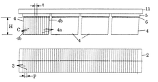
図1および図2は、従来のワイヤソーにおいて、複数例えば4個のワーク4を同時に切断するときの一般的な方法を示している。それぞれのワーク4は、上面の接着層6によってガラス製のホルダー5に保持される。これらのワーク4は、ホルダー5を介してワークプレート11の下面に、ワイヤ3の走行方向に対して直交方向に所定の間隔を置いて接着され、ワークプレート11は、図示しない適当なクランプ手段によりワイヤソーのワークテーブルに固定される。
1 and 2 show a general method for simultaneously cutting a plurality of, for example, four
ワイヤ3は、図示しない送り出し装置から引き出され、溝付きの案内ローラ23を経由して、複数のメインローラ2の間に、各メインローラ2の溝2aにそって多重に平行な状態として巻き掛けられてから、溝付きの案内ローラ24を経由して図示しない巻き取り装置に送り出される。メインローラ2の各溝2aは、図2の円中の拡大断面図に示すように、一般にV字形の環状溝であり、メインローラ2の外周面で独立している。このため、ワイヤ3は、ワーク4に向き合う切断域、すなわち図示の例で上側域でメインローラ2の中心線に対して直交しているが、ワーク4に向き合わない域、すなわち図示の例で下側域で、隣り合う一方の溝2aから他方の溝2aへと変位し、メインローラ2の中心線に対し斜行している。なお、ワイヤ3の斜行部分は、図2上では上下の線の複雑化を避けるために、省略されている。
The
切断加工時に、ワイヤ3は、メインローラ2の回転によって走行状態となり、複数のワーク4に押し当てられる。これによって、ワーク4は、ワイヤ3の間のワイヤピッチP、すなわちメインローラ2の溝ピッチに応じて目標の厚みtに切断される。このときの切り口は、図1の左側端のワーク4に示すように、平行な切断線Cにより表される。
During the cutting process, the
ワーク4が端部で凹凸を形成していたり、あるいは図1に示すように、例えば菱形のように変形していると、切断完了時点で、ワーク4の両端に厚みt未満の端材4bが発生しており、それらの端材4bの間で目標の厚みtの良品4aが得られる。なお、端材4bは、通常、良品4aの切断高さHよりも短いものとなっている。
If the
端材4bの一部は、切断中に接着層6を失ってホルダー5から分離して離散し、その途中でワイヤ3に干渉したり、メインローラ2の溝2aに入ったりして、ワイヤ飛びや、ワイヤ断線を起こし、あるいは回転部品に干渉したりして、回転部分の不良を引き起こす。このため、端材4bの離散は、ワイヤソーの機能保持、危険防止の観点からも問題であり、未然に防止しなければならない。
A part of the
一方、特許文献1は、メインローラの外側において、ワイヤをピッチ移動させることでメインローラへ戻すワイヤ巻き掛け位置を全体に1ピッチずらす、ことを開示している。しかし、その技術は、端材の分離や離散、これによるワイヤソーの機能保持や、危険防止を意図したものではない。したがって、上記の問題は、特許文献1の技術をただ単にそのまま転用しても、解決できない。
On the other hand,
したがって、本発明の課題は、ワークの切断中および切断完了時点でも、ワークの端材をホルダーに拘束し、離散しないようにして、ワイヤに対する端材の干渉や、メインローラの溝に対する端材の入り込み、端材と回転部品との干渉を無くし、ワイヤ飛びや、ワイヤ断線、さらに回転部分の不良を未然に防止することである。 Therefore, the problem of the present invention is that the workpiece end material is constrained to the holder even during the cutting of the workpiece and at the time when the cutting is completed, so that the workpiece is not separated, so that the end material interferes with the wire or the end material against the groove of the main roller. Intrusion, interference between the end material and the rotating parts is eliminated, and wire jumping, wire breakage, and defective rotating parts are prevented in advance.
上記の課題のもとに、本発明は、ワイヤソーによるワークの切断過程において、端材の発生位置でワイヤをメインローラの溝について飛び越し(スキップ)させ、切断完了後においても、端材をホルダーに拘束し、離散しないようにしている。 Based on the above problems, the present invention allows the wire to jump over the groove of the main roller at the position where the end material is generated in the cutting process of the workpiece by the wire saw, and the end material is used as a holder even after the completion of the cutting. It is restrained so that it does not become discrete.
具体的に記載すると、本発明に係るワーク切断方法は、複数の平行なメインローラの間に多重に巻き掛けられたワイヤを走行させ、走行状態のワイヤに、ホルダーに拘束されているワークを押し当てることによって、ワークを目標の厚みに切断するワイヤソーにおいて、ワークの目標の厚み方向で、ワークの両端部にホルダーとの拘束部分を残しながら、ワークについて良品を確保できる範囲に、ワーク切断域を設定しておき、このワーク切断域内でワイヤのワイヤピッチを目標の厚みに対応する値に設定するとともに、ワーク切断域以外で、ワークと干渉する範囲にワイヤを不存在とするワイヤ飛ばし域を設定している(請求項1)。 More specifically, the workpiece cutting method according to the present invention travels a wire wound in a multiple manner between a plurality of parallel main rollers, and pushes the workpiece constrained by the holder to the traveling wire. In the wire saw that cuts the workpiece to the target thickness by applying the workpiece, the workpiece cutting area is set within the range in which a non-defective product can be secured while leaving the constrained part with the holder at both ends of the workpiece in the target thickness direction of the workpiece. Set and set the wire pitch of the wire within the workpiece cutting area to a value corresponding to the target thickness, and set the wire skipping area where there is no wire outside the workpiece cutting area and in the range where it interferes with the workpiece (Claim 1).
ここでワークについて、ワークの目標の厚みで、ワークの切断高さ、切断長さ、および切断高さと切断長さとの組み合わせのうち何れか1つにおいて所定の寸法が確保されたものを前記良品としている(請求項2)。したがって、ワーク切断域は、目標の厚みを確保しながら、ワークの切断高さのみ、切断長さのみ、切断高さと切断長さとの組み合わせ、の3つの態様によって決定される。 Here, with respect to the workpiece, a workpiece in which a predetermined dimension is secured in any one of the workpiece cutting height, the cutting length , and the combination of the cutting height and the cutting length as the non- defective product. (Claim 2). Accordingly, the workpiece cutting zone, while ensuring the target thickness, the cutting height of the work only, cut length only, the combination of the cutting height and cut length is determined by three aspects of the.
また、本発明は、複数の平行なメインローラの間に多重に巻き掛けられたワイヤを走行させ、走行状態のワイヤに、ホルダーに拘束されているワークを押し当てることによって、ワークを目標の厚みに切断するワイヤソーにおいて、ワークの目標の厚み方向で、ワークの両端部にホルダーとの拘束部分を残しながら、ワークについて良品を確保できる範囲に、ワーク切断域を設定しておき、このワーク切断域内でワイヤのワイヤピッチを目標の厚みに対応する値に設定すると共に、ワーク切断域以外で、ワークと干渉する範囲にワイヤを不存在とするワイヤ飛ばし域を設定し、このワイヤ飛ばし域でメインローラの外側にワイヤ飛ばし用ローラを配置し、ワイヤをワイヤ飛ばし用ローラに巻き掛けることによって、ワイヤをメインローラの中心線の方向に変位させ、ワイヤ飛ばし域を形成して、ワーク切断用ワイヤ巻き幅変更装置を構成している(請求項3)。 Further, the present invention allows a wire wound in a multiple manner between a plurality of parallel main rollers to travel, and presses the workpiece restrained by the holder against the wire in the traveling state, thereby causing the workpiece to have a target thickness. In a wire saw that cuts into a workpiece, in the target thickness direction of the workpiece, the workpiece cutting area is set within a range in which a non-defective product can be ensured while leaving a restrained portion with the holder at both ends of the workpiece. In addition to setting the wire pitch of the wire to a value corresponding to the target thickness, a wire skipping area in which no wire is present is set in a range that interferes with the work other than the work cutting area, and the main roller is set in this wire skipping area. The wire blow roller is placed outside the wire and the wire is wound around the wire blow roller so that the wire is placed inside the main roller. It is displaced in the direction of the line, to form a wire skip area, and a work cutting wire winding width changing device (claim 3).
このワーク切断用ワイヤ巻き幅変更装置においても、ワークについてワークの目標の厚みで、ワークの切断高さ、切断長さ、および切断高さと切断長さとの組み合わせのうち何れか1つにおいて所定の寸法が確保されたものを前記良品とする(請求項4)。したがって、ワーク切断域は、目標の厚みを確保しながら、ワークの切断高さのみ、切断長さのみ、切断高さと切断長さとの組み合わせ、の3つの態様によって決定される。 Also in this workpiece cutting wire winding width changing device, the workpiece has a predetermined dimension at any one of the workpiece cutting height, the cutting length , and the combination of the cutting height and the cutting length at the target thickness of the workpiece. Is ensured as the non-defective product (claim 4). Accordingly, the workpiece cutting zone, while ensuring the target thickness, the cutting height of the work only, cut length only, the combination of the cutting height and cut length is determined by three aspects of the.
さらに、ワーク切断用ワイヤ巻き幅変更装置において、本発明は、隣り合うワークのワイヤ飛ばし域内に、2個のワイヤ飛ばし用ローラを配置し、2個のワイヤ飛ばし用ローラの軸線をメインローラの中心線に対し平行とするとともに、2個のワイヤ飛ばし用ローラの間に複数のガイドローラを配置し、これらのガイドローラの軸線をメインローラの中心線に対して交差させ、2個のワイヤ飛ばし用ローラおよびガイドローラにワイヤを順次に巻き掛けて、ワイヤ飛ばし域においてワークと干渉する範囲でワイヤを不存在としている(請求項5)。 Furthermore, in the wire cutting width changing device for cutting a workpiece, the present invention is arranged such that two wire blowing rollers are arranged in a wire flying area of an adjacent workpiece, and the axis of the two wire blowing rollers is the center of the main roller. Parallel to the line, a plurality of guide rollers are arranged between the two wire blowing rollers, and the axis of these guide rollers intersects the center line of the main roller, for two wire blowing A wire is sequentially wound around the roller and the guide roller, and the wire is made nonexistent within a range where it interferes with the workpiece in the wire skipping area.
ワーク切断用ワイヤ巻き幅変更装置において、本発明は、隣り合うワークのワイヤ飛ばし域内に、1または2個のワイヤ飛ばし用ローラを配置し、ワイヤ飛ばし用ローラの軸線をメインローラの中心線に対し斜め方向に設定し、ワイヤ飛ばし用ローラにワイヤを巻き掛けて、ワイヤ飛ばし域においてワークと干渉する範囲でワイヤを不存在としている(請求項6)。 In the wire cutting width changing device for cutting a workpiece, the present invention is arranged such that one or two wire blowing rollers are arranged in a wire blowing area of an adjacent workpiece, and the axis of the wire blowing roller is set to the center line of the main roller. It is set in an oblique direction, the wire is wound around a wire blow roller, and the wire is made nonexistent within a range where it interferes with the workpiece in the wire blow area (Claim 6).
また、ワーク切断用ワイヤ巻き幅変更装置において、本発明は、ワイヤ飛ばし用ローラを異なるブラケットにより回転自在に保持し、それぞれのブラケットをメインローラに対し平行な方向に移動自在に設けている(請求項7)。 Further, in the wire cutting width changing device for cutting a workpiece, the present invention is configured to hold the wire blowing roller rotatably by different brackets and to move each bracket in a direction parallel to the main roller. Item 7).
ワーク切断用ワイヤ巻き幅変更装置において、本発明は、ワイヤ飛ばし用ローラを同じブラケットによって回転自在に保持し、そのブラケットをメインローラに対し平行な方向に移動自在に設けている(請求項8)。 In the wire cutting width changing device for cutting a workpiece, the present invention is configured to hold a wire blowing roller rotatably by the same bracket, and to move the bracket in a direction parallel to the main roller. .
ワーク切断用ワイヤ巻き幅変更装置において、本発明は、ワイヤ飛ばし用ローラをブラケットに対して傾斜軸受けホルダーおよび支点軸によって傾斜角度調整自在に取り付けている(請求項9)。 In the wire cutting width changing device for cutting a workpiece, according to the present invention, a wire blowing roller is attached to a bracket so that the inclination angle can be adjusted by an inclination bearing holder and a fulcrum shaft.
本発明に係るワーク切断方法によると、ワーク切断域でワークが目標の厚みで良品として切断され、良品がホルダーに拘束されており、また、ワークの両端部のワイヤ飛ばし域において切断後に端材が発生するが、それらの端材は、ワイヤ飛ばし域でのワイヤの不存在によって、細かく切断されず、良品と同様にホルダーに拘束されたままになっている。したがって、ワイヤによるワークの切断過程において、端材がホルダーから分離して離散しないため、ワイヤに対する端材の干渉や、メインローラの溝に対する端材の入り込みがなくなり、端材と回転部品との干渉もなくなることから、ワイヤ飛びや、ワイヤ断線、さらに回転部分の不良が未然に防止できる(請求項1)。 According to the workpiece cutting method according to the present invention, the workpiece is cut as a non-defective product with a target thickness in the workpiece cutting region, the non-defective product is restrained by the holder, and the end material is cut after cutting in the wire skipping region at both ends of the workpiece. Although generated, these end materials are not cut finely due to the absence of the wire in the wire skipping region, and remain in the holder like the non-defective product. Therefore, in the process of cutting the workpiece by the wire, the end material is not separated from the holder, so that the end material does not interfere with the wire and the end material does not enter the groove of the main roller, and the end material interferes with the rotating part. Therefore, it is possible to prevent wire jumping, wire breakage, and defective rotating parts (claim 1).
本発明に係るワーク切断方法において、切断域がワークの切断高さ、切断長さなどを考慮して決定されると、ワークとしてのシリコンインゴットなどの形状や製品の品質に応じて、適切な切断域が設定できる(請求項2)。 In the work cutting method according to the present invention, the cutting zone cutting height of the workpiece, when it is determined by considering the etc. cut length Sana, depending on the quality of the shape and the product, such as a silicon ingot as a work, a suitable A cutting area can be set (claim 2).
本発明に係るワーク切断用ワイヤ巻き幅変更装置によると、上記のワーク切断方法と同様にワーク切断域でワークが目標の厚みの良品として切断され、良品がホルダーに拘束されており、またワークの両端部のワイヤ飛ばし域において切断後に端材が発生するが、それらの端材は、ワイヤ飛ばし域でのワイヤの不存在によって切断されず、良品と同様に、ホルダーに拘束されている。したがって、ワイヤによるワークの切断過程において、端材がホルダーから分離せず、離散もしない。このため切断の完了後に、端材は良品とともにホルダーと一緒に回収できることになる。また、ワイヤに対する端材の干渉や、メインローラの溝に対する端材の入り込みがなく、端材と回転部品との干渉もなくなり、ワイヤ飛び、ワイヤ断線、さらに回転部分の不良が未然に防止できる(請求項3)。特に、ワイヤ飛ばし域がメインローラの外側に配置したワイヤ飛ばし用ローラにワイヤを巻き掛けることによって形成できるから、メインローラなどの構成を変える必要がなく、切断加工の実施が容易となる(請求項3)。 According to the wire cutting width changing device for cutting a workpiece according to the present invention, the workpiece is cut as a non-defective product having a target thickness in the workpiece cutting area, and the non-defective product is restrained by the holder in the same manner as the above-described workpiece cutting method. End materials are generated after cutting in the wire skipping regions at both ends, but these end materials are not cut due to the absence of wires in the wire skipping regions and are constrained by the holder in the same way as non-defective products. Therefore, in the process of cutting the workpiece by the wire, the end material is not separated from the holder and is not separated. For this reason, after completion of cutting, the end material can be collected together with the non-defective product together with the holder. In addition, there is no interference of the end material to the wire, and the end material does not enter the groove of the main roller, and there is no interference between the end material and the rotating part, and it is possible to prevent wire jumping, wire breakage, and defective rotating parts ( Claim 3). In particular, since the wire skipping area can be formed by winding a wire around a wire skipping roller disposed outside the main roller, it is not necessary to change the configuration of the main roller or the like, and the cutting process can be easily performed. 3).
ワーク切断用ワイヤ巻き幅変更装置においても、ワーク切断方法と同様に、切断域がワークの切断高さ、切断長さなどを考慮して決定されると、ワークとしてのシリコンインゴットなどの形状や製品の品質に応じて、適切な切断域が設定できる(請求項4)。 Also in the work cutting wire winding width changing device, similarly to the workpiece cutting method, the cutting zone cutting height of the workpiece, when it is determined in consideration of the etc. disconnect length Sana, shape, such as a silicon ingot as a workpiece An appropriate cutting area can be set according to the quality of the product.
ワーク切断用ワイヤ巻き幅変更装置において、2個のワイヤ飛ばし用ローラがワイヤ飛ばし域に配置されており、ワイヤ飛ばし用ローラの間に複数のガイドローラが介在しているから、ワイヤ飛ばし域の寸法の変化に対して、ワイヤ飛ばし用ローラの位置変更によって簡単に対応でき、しかもワイヤ飛ばし用ローラ直径は、小さいもので足りる(請求項5)。 In the wire cutting width changing device for cutting a workpiece, two wire blowing rollers are arranged in the wire blowing area, and a plurality of guide rollers are interposed between the wire blowing rollers. This change can be easily dealt with by changing the position of the wire blow-off roller, and the diameter of the wire blow-off roller may be small (Claim 5).
ワーク切断用ワイヤ巻き幅変更装置において、隣り合うワークのワイヤ飛ばし域内に、1または2個のワイヤ飛ばし用ローラがメインローラの中心線に対し斜め方向に配置されていると、ワイヤ飛ばし用ローラの斜め方向の角度の調節により、ワイヤ飛ばし域の寸法の変化に柔軟に対応でき、しかも、2個のワイヤ飛ばし用ローラのときに、それらの直径は小さいもので足りる(請求項6)。 In the wire cutting width changing device for cutting a workpiece, if one or two wire blowing rollers are arranged in an oblique direction with respect to the center line of the main roller in the wire flying area of the adjacent workpiece, the wire blowing roller By adjusting the angle in the oblique direction, it is possible to flexibly cope with changes in the dimensions of the wire skipping area, and it is sufficient that the diameters of the two wire skipping rollers are small.
ワーク切断用ワイヤ巻き幅変更装置において、ワイヤ飛ばし用ローラが異なるブラケットによって回転自在に保持され、それぞれのブラケットがメインローラに対し平行な方向に移動自在に設けられていると、ワーク切断域の範囲の変化や、ワイヤ飛ばし域の範囲の変化、換言すると、ワークの寸法の変化や、ワークの配置時の間隔の変化に対しても柔軟に対応できる(請求項7)。 In the wire cutting width changing device for cutting a workpiece, the wire blowing roller is rotatably held by different brackets, and each bracket is provided so as to be movable in a direction parallel to the main roller. It is also possible to flexibly cope with changes in the range of wires, changes in the range of the wire skipping area, in other words, changes in the dimensions of the workpiece and changes in the interval at the time of workpiece placement.
ワーク切断用ワイヤ巻き幅変更装置において、ワイヤ飛ばし用ローラが同じブラケットに保持されていると、ワーク切断域の寸法が変化するが、ワイヤ飛ばし域が殆ど変化しないときに、ブラケットの移動によって、ワイヤ飛ばし域を変化させないまま、切断工程のセッテングが簡単にできる(請求項8)。 In the wire cutting width changing device for workpiece cutting, if the wire blowing roller is held by the same bracket, the size of the workpiece cutting area changes, but when the wire flying area hardly changes, the wire moves by moving the bracket. The setting of the cutting process can be easily performed without changing the flying area.
ワーク切断用ワイヤ巻き幅変更装置において、ワイヤ飛ばし用ローラがブラケットに対して傾斜軸受けホルダーおよび支点軸により傾斜角度調整自在に取り付けていると、ワーク切断域およびワイヤ飛ばし域の寸法の変化に対して、傾斜軸受けホルダーの傾斜角度の調整によって両方の寸法の変化に対して、同時に対処できるため、それらの寸法の変化に対して、柔軟に対応できる(請求項9)。 In the wire cutting width changing device for workpiece cutting, if the wire blow roller is attached to the bracket so that the tilt angle can be adjusted by the tilt bearing holder and the fulcrum shaft, the workpiece cutting area and the wire flying area can be changed. Since both the dimensional changes can be dealt with simultaneously by adjusting the tilt angle of the tilt bearing holder, the dimensional changes can be flexibly dealt with (claim 9).
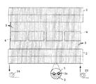
図3および図4は、本発明に係るワーク切断方法によって、複数、例えば4個のワーク4を同時に切断するときの態様を示している。これらの図3および図4において、ワイヤソー1は、一例として2本の平行なメインローラ2の間で多重に巻き掛けられたワイヤ3を走行させ、走行状態のワイヤ3に4個のワーク4を押し当てることによって、ワーク4を目標の厚みtに切断する。
3 and 4 show a mode when a plurality of, for example, four
ワイヤ3は、図示しない送り出し装置から引き出され、溝付きの案内ローラ23を経由して、複数のメインローラ2の間に、各メインローラ2の溝2aにそって多重に巻き掛けられ、ワーク4に向き合う位置で平行な切断域を形成してから、溝付きの案内ローラ24を経由して図示しない巻き取り装置に送り出される。
The
メインローラ2の各溝2aは、図4の円中の拡大断面図に示すように、V字形の環状溝であり、メインローラ2の外周面でワイヤピッチPに対応して形成され、互いに独立している。すべてのワイヤ3は、ワーク4に向き合う切断域、すなわち図示の例で上側域で、2本のメインローラ2の対応する溝2aに納まって平行な状態となっているから、メインローラ2の中心線に対して直交しているが、ワーク4に向き合わない非切断域、すなわち図示の例で下側域で、隣り合う一方の溝2aから他方の溝2aへと変位しているため、メインローラ2の中心線に対して斜行していることになる。このワイヤ3の斜行部分は、図4上では線の複雑化を避けるために、部分的に省略されている。
Each
ワーク4は、上面の接着層6によって例えばガラス製のホルダー5に固定されており、このホルダー5を介してワークプレート11にワイヤ3の走行方向に対し直交方向に所定の間隔を置いて配置され、図示しない適当なクランプ手段によりワイヤソーのワークテーブルに取付けられる。
The
そして、本発明のワーク切断方法は、図3に示すように、ワーク4の切断前に、各ワーク4毎に、切断線Cに平行な線によってワーク切断域Aを設定し、また4個のワーク4の間およびワーク4の配置方向の端部毎に、切断線Cに平行な線によってワイヤ飛ばし域Bを設定する、ことを特徴としている。ワーク切断域Aは、ワーク4の目標の厚みtの方向、つまり4個のワーク4の配置方向において、ワーク4の両端部でホルダー5との拘束部分すなわちホルダー5に対するワーク4の接着層6を残しながら、ワーク4について良品4aとする必要な寸法すなわち切断高さHを確保できる範囲でワーク4毎に設定される。このワーク切断域A内で、ワイヤピッチPは目標の厚みtに対応する値に設定される。
Then, as shown in FIG. 3, the workpiece cutting method of the present invention sets a workpiece cutting area A by a line parallel to the cutting line C for each
また、ワイヤ飛ばし域Bは、ワーク切断域A以外、すなわち隣接する2つのワーク4の間および配置方向の端部位置のワーク4でワーク切断域Aの外側に、前記ワーク4の両端部で残された接着層6を含み、かつワーク4について良品4aとする必要な切断高さHを確保できる範囲に設定される。このワイヤ飛ばし域Bの設定のために、ワイヤ飛ばし用ローラとしての例えば1個の溝付きのスキップローラ71が用いられる。スキップローラ71は、両端部のワイヤ飛ばし域B以外の3つのワイヤ飛ばし域B内で、メインローラ2の外側に配置され、スキップローラ71の軸線をメインローラ2の中心線に対して斜め方向に設定されている。両端部のワイヤ飛ばし域Bでは、そこにワイヤ3を巻き掛けないことによって、ワイヤ飛ばし域Bが設定される。
Further, the wire skipping area B is left outside the workpiece cutting area A, that is, between the two
図示の例において、ワイヤ3は、一方のワーク切断域Aから出て、メインローラ2から離れ、スキップローラ71に巻き掛けられてから、他方のワーク切断域Aに入り、メインローラ2に巻き掛けられるため、あたかもオープンベルトのようになっている。したがって図3から明らかなように、スキップローラ71の直径は、一方のワーク切断域Aから出るワイヤ3の位置(アウト側の位置)と他方のワーク切断域Aに入るワイヤ3の位置(イン側の位置)とをつなぐ対角線の長さに相当する寸法のものが好ましいが、許容範囲内で対角線の長さよりも小さい寸法の直径での運用もあり得る。このようにして、ワイヤ3は、ワイヤ飛ばし域Bでスキップローラ71に巻き掛けられるため、ワイヤ飛ばし域Bでメインローラ2の複数の溝2aを飛び越して、大きな間隔を形成しており、ワイヤ飛ばし域Bにおいて、不存在となっている。
In the illustrated example, the
ワーク4の切断時に、ワイヤソー1は、メインローラ2の間で多重に巻き掛けられたワイヤ3を走行させ、走行状態のワイヤ3に4個のワーク4を同時に押し当てることにより、ワーク切断域Aの範囲で対応のワーク4を目標の厚みtに切断する。切断の完了時点での切り口は、図3の左側端のワーク4に関して例示すように、平行な複数の切断線Cにより表される。
When the
ワーク切断域A内で、目標の厚みtに切断されたワーク4は、複数枚の良品4aとなる。それぞれの良品4aは、切断の完了後も、接着層6によってホルダー5に固定され、拘束されているため、そこから分離しない。したがって、複数枚の良品4aは、ホルダー5と共に製品として取り外せる状態になってる。
The
一方、ワイヤ飛ばし域Bにおいて、目標の厚みtに切断されたワーク4は、端材4bとなる。端材4bは、各ワーク4の両端部に発生するが、良品4aと同様に、接着層6を失っておらず、依然として接着層6によりホルダー5に拘束されたままであり、そこから分離せず、離散することもない。
On the other hand, in the wire skipping zone B, the
したがって、端材4bは、ワイヤ3に干渉したり、メインローラ2の溝2aに入ったり、あるいは回転部品に干渉したりして、ワイヤ飛びや、ワイヤ断線、さらに回転部分の不良を引き起こすことはない。しかも、切断完了後に、両端の端材4bは、良品4aとともにホルダー5と一緒に回収できることになる。
Therefore, the
ワイヤ飛ばし域Bの範囲内において、ワーク4の存在しない位置、例えば2つのワーク4の間隔空間の位置にワイヤ3が存在したとしても、ワーク切断時に、その位置のワイヤ3は、ワーク4と干渉せず、もちろんワーク4を切断することもないから、その範囲において端材4bの離散という問題はありえない。したがって、ワイヤ飛ばし域Bの範囲内において、ワイヤ3は、実質的には、ワーク4と干渉する範囲で不存在であればよいことになる。なお、ワーク4が図3の例のように、菱形に変形している場合に、もし、切断後において、端材4bが切断高さHを満たしていないとき、その端材4bは、図1の左端の端材4bと同じとなり、離散するものとなる。このことから、図3の例によると、端材4bについても切断高さHは必要といえる。
Even if the
図5は、図3および図4の1個のスキップローラローラ71に代えて、ワイヤ飛ばし用ローラとしての小さな直径の2個のスキップローラ72、73をアウト側のワイヤ3の位置およびイン側のワイヤ3の位置に斜めに配置し、これらのスキップローラ72、73にワイヤ3を斜めに巻き掛けて、ワイヤ飛ばし域Bにおいてワイヤ3を不存在とする、例を示している。この例によると、2個のスキップローラ72、73の直径は、小さいもので足りる。
5 replaces one
図6は、ワイヤ3のアウト側の位置およびイン側の位置において、小さな直径の2個のスキップローラ72、73を配置し、それらの軸線をメインローラ2の中心線に対して平行とするとともに、スキップローラ72、73の間に2個のガイドローラ81、82を配置し、ガイドローラ81、82の軸線をメインローラ2の中心線に対して交差させ、アウト側のスキップローラ72、ガイドローラ81、82およびイン側のスキップローラ73にワイヤ3を順次に巻き掛けて、ワイヤ飛ばし域Bにおいて、ワイヤ3を不存在とする、例を示している。この図6の例によると、2個のスキップローラ72、73は、小さいもので足りる。しかも、スキップローラ72、73の軸線の方向は、ワイヤ飛ばし域Bの幅寸法の変化にかかわらず、常にメインローラ2の中心線に対して平行となり、ワイヤ飛ばし域Bの寸法の変化のときに、変更しなくてもよくなる。
In FIG. 6, two
さらに図7および図8は、2個のスキップローラ71を非切断域のワイヤ3よりも外側、この例によると下方に配置し、2個のスキップローラ71間で1本のワイヤ3を一方のワーク切断域Aから他方のワーク切断域Aへ飛び越しさせる例である。この結果、ワイヤ3は、ワイヤ飛ばし域Bの下方において、一方のスキップローラ71から他方のスキップローラ71へと斜行し、一方のメインローラ2から他方のメインローラ2に巻き掛けられる間に、ワイヤ飛ばし域Bを飛び越すことになる。ちなみに、前記図3ないし図6の例によると、ワイヤ3は、各メインローラ2に対してワイヤ3のアウト側の位置からイン側の位置に移行する過程でワイヤ飛ばし域Bを飛び越している。なお、2点鎖線で示すように、2個のスキップローラ71に巻き掛けたワイヤ3が非切断域のワイヤ3より外側に位置すれば、スキップローラ71の位置は、想像線で例示するように、適当に設定できる。もちろん、スキップローラ71の間にアイドルローラを介在させることもできる。
Further, in FIGS. 7 and 8, two
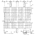
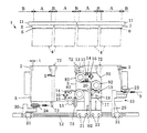
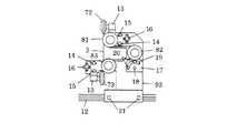
次に、図9ないし図12は、上記のワーク切断方法を実際に実施するために、図6の例を基本的な構成として、その構成、すなわち2個の溝付きのスキップローラ72、73を採用しながら、これに3個の溝付きのガイドローラ81、82、83を付加して、本発明のワーク切断用ワイヤ巻き幅変更装置10を構成した具体例を示している。なお、図9および図10において、各図の後ろ側の一部部品は、前側の部分と重なり合って複雑になることから省略されている。
Next, in order to actually implement the above-described workpiece cutting method, FIGS. 9 to 12 show the configuration of FIG. 6 as a basic configuration, that is, two
図9および図10において、上側のスキップローラ72および上側の溝付きのガイドローラ81は、それぞれ軸部分で軸受けホルダー13により回転自在に保持され、一方のブラケット91に取り付けられている。また、下側のスキップローラ73および下側の溝付きのガイドローラ83は、それぞれ軸部分で軸受けホルダー13によって回転自在に保持され、他方のブラケット92に取り付けられている。
9 and 10, the
上側の軸受けホルダー13は、上下の長孔14、長孔14ごとの取り付けボルト15によって対応のブラケット91に対してメインローラ2の中心線方向に位置調整自在に取り付けられ、ブラケット91と各軸受けホルダー13との間に取り付けたアジャストスクリュウ16によって、メインローラ2の中心線の方向に位置調整できるようになっている。
The
なお、中間位置の溝付きのガイドローラ82は、軸受けホルダー17により回転自在に保持され、ブラケット91に対して支軸18によって回動自在に取り付けられ、円弧孔19と締め付けボルト20によって、必要に応じてワイヤ3をゆるめるために、変位自在に取り付けられている。
The
下側の軸受けホルダー13は、上側の軸受けホルダー13と同様に、上下の長孔14、長孔14ごとの取り付けボルト15によって対応のブラケット92に対してメインローラ2の中心線方向に位置調整自在に取り付けられ、ブラケット92と各軸受けホルダー13との間に取り付けたアジャストスクリュウ16によって、メインローラ2の中心線の方向に位置調整できるようになっている。
Similarly to the
図12に示すように、2個のブラケット91、92は、それぞれ下部でメインローラ2に対し平行な断面C形のレール12に対し、各ブラケット91、92側の固定ボルト21とレール12の内部の抜け止めスライドナット22によって適当な位置に固定できるようになっている。2個のブラケット91、92の位置調整によって、ワイヤ飛ばし域Bは自由に設定できる。
As shown in FIG. 12, the two
図9に示すように、ワイヤ3は、図示しない送り出し側のリールから引き出され、入口側で溝付きの案内ローラ23を経て、メインローラ2の溝に巻き掛けられ、4個のワーク4に対応させてワーク切断域Aを形成し、ワーク4の間および配列端でワイヤ飛ばし域Bを形成した後、出口側で溝付きの案内ローラ24を経て、図示しない巻き取り側のリールに巻き取られる。ワーク4の間でのワイヤ飛ばし域Bは、3箇所であるから、対となるスキップローラ72、73は、3箇所に設置されている。
As shown in FIG. 9, the
なお、溝付きの案内ローラ23、24も、案内用のブラケット29、30に回転自在に保持され、ブラケット91、92と同様に、断面C形のレール12に対し、固定ボルト21とレール12の内部の抜け止めスライドナット22によって適当な位置に固定できるようになっている。
The
図11に示すように、ワーク切断域Aとワイヤ飛ばし域Bとの境界位置において、ワイヤ3は、あたかもクロスベルト掛けのようにメインローラ2と上下のスキップローラ72、73との間で交差する状態として巻き掛けられる。この交差状態の巻き掛けは、メインローラ2に対するワイヤ3の巻き掛け角度を大きくして、メインローラ2の溝2aの内部でのワイヤ3の不安定な動きをなくするために採用されている。
As shown in FIG. 11, at the boundary position between the workpiece cutting area A and the wire skipping area B, the
図9ないし図12の例によっても、ワーク4の切断動作は、図3および図4の方法と同様に行われる。図9ないし図12の例によると、上下のスキップローラ72、73が異なるブラケット91、92により独立に支持されているから、ワーク切断域Aやワイヤ飛ばし域Bの範囲の変化、換言すると、ワーク4の寸法の変化や、ワーク4の配置間隔の変化に対して柔軟に対応できる。
9 to 12 also, the cutting operation of the
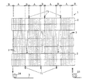
次に、図13は、スキップローラ72、73を同じブラケット93により回転自在に保持し、そのブラケット93をメインローラ2に対し平行なレール12に移動自在に取り付ける例である。
Next, FIG. 13 is an example in which the
図13の例によると、ワーク切断域Aの寸法が変化するが、ワイヤ飛ばし域Bが殆ど変化しないときに、レール12に対するブラケット93の移動によって、ワイヤ飛ばし域Bを変化させないまま、簡単にセッテングができる。
According to the example of FIG. 13, the dimension of the workpiece cutting area A changes, but when the wire skipping area B hardly changes, the setting of the
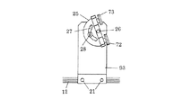
さらに、図14は、図5の2個のスキップローラ72、73に対応する例であり、スキップローラ72、73を共通のブラケット93に対して傾斜軸受けホルダー25および支点軸26により傾斜角度調整自在に取り付けた具体例である。調整後の傾斜軸受けホルダー25の位置は、傾斜軸受けホルダー25の円弧状孔27に対してブラケット93側の位置決めボルト28を締め付けることによって固定される。
Further, FIG. 14 is an example corresponding to the two
図14の例において、2個のスキップローラ72、73は、図3および図4のような1個のスキップローラ71によって置き換えることも可能である。
In the example of FIG. 14, the two
図14の例によると、ワーク切断域Aおよびワイヤ飛ばし域Bの寸法の変化に対して、傾斜軸受けホルダー25の傾斜角度の調整によって両方の寸法の変化に対し同時に対処できるため、それらの寸法の変化に対して、柔軟に対応できる。
According to the example of FIG. 14, since changes in the dimensions of the workpiece cutting area A and the wire skipping area B can be simultaneously dealt with by changing the inclination angle of the
以上の例は、ワーク4から良品4aを切断するために、ワーク4の目標の厚みtと切断高さHとを考慮して、切断域Aを決定している。しかし、切断域Aは、立方体のワーク4から良品4aを切断するときに、ワーク4の形状や、側面の凹凸形状の有無にもよるが、切断高さHの外に、切断長さLも必要な寸法となる。
Above example, in order to cut the non-defective 4a from the
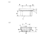
図15は、他の形状のワーク4を示している。図15において、ワーク4は、平面形状として逆台形であり、端部の三角形の上面で他の上面よりも下がり傾向にあり、ゆるやかな傾斜面となっている。このため、両端部の傾斜面は、部分的に接着層5から離れており、切断時に、離れている部分で端材4bとなって離散する。
FIG. 15 shows a
したがって、図15の例において、切断域Aは、ワーク4の目標の厚みt、必要な切断高さHの寸法の外に、有効な切断長さLを考慮して決定される。このように切断域Aの設定に際して、ワーク4について必要な寸法は、ワーク4としてのシリコンインゴットの形状や、製品の品質、特に側面の凹凸形状の有無に応じて、ワーク4の目標の厚みt、および切断高さH、切断長さL、または切断高さHと切断長さLとの組み合わせということになる。実際には、ワーク4の目標の厚みtと切断高さHのみ、または切断長さLのみとを確保すれば、事実上、切断域Aは、殆ど有為に設定できることが多い。
Thus, in the example of FIG. 15, the cutting zone A, the target thickness t of the
なお、メインローラ2は、2本に限らず、それ以上、例えば3本、あるいは4本であってもよい。図16は、3本のメインローラ2を三角形の各頂角の位置に平行に配置した例であり、また図17は、4本のメインローラ2を四角形の各頂角の位置に平行に配置し、ワイヤ3の上下の位置を切断域とし、ワーク4を上下に2段としてに配置する例である。
The number of
以上の具体例は、配列状態の複数のワーク4を同時に切断する態様を示しており、作用効果および切断効率は、複数のワーク4の同時切断の態様において顕著である。しかし、本発明の目的すなわち端材4bの離散防止は、1個のワーク4を切断するときにも成り立つから、本発明は、複数のワーク4の同時切断の態様に限定されず、1個のワーク4の切断態様を含む。
The above specific example shows an aspect in which a plurality of
1 ワイヤソー
2 メインローラ 2a 溝
3 ワイヤ
4 ワーク 4a 良品 4b 端材
5 ホルダー
6 接着層
71、72、73 ワイヤ飛ばし用ローラとしてのスキップローラ
81、82、83 ガイドローラ
91、92、93 ブラケット
10 ワーク切断用ワイヤ巻き幅変更装置
11 ワークプレート
12 レール
13 軸受けホルダー
14 長孔
15 取り付けボルト
16 アジャストスクリュウ
17 軸受けホルダー
18 支軸
19 円弧孔
20 締め付けボルト
21 固定ボルト
22 抜け止めスライドナット
23 案内ローラ
24 案内ローラ
25 傾斜軸受けホルダー
26 支点軸
27 円弧状孔
28 位置決めボルト
29 ブラケット
30 ブラケット
DESCRIPTION OF
A ワーク切断域
B ワイヤ飛ばし域
C 切断線
H 切断高さ
L 切断長さ
P ワイヤピッチ
t 目標の厚み
A Work cutting area B Wire skipping area C Cutting line H Cutting height L Cutting length P Wire pitch t Target thickness
Claims (9)
ワークの目標の厚み方向で、ワークの両端部にホルダーとの拘束部分を残しながら、ワークについて良品を確保できる範囲に、ワーク切断域を設定しておき、このワーク切断域内でワイヤのワイヤピッチを目標の厚みに対応する値に設定するとともに、ワーク切断域以外で、ワークと干渉する範囲にワイヤを不存在とするワイヤ飛ばし域を設定する、ことを特徴とするワーク切断方法。 In a wire saw that cuts a workpiece to a target thickness by running a wire wound in multiple between a plurality of parallel main rollers, and pressing the workpiece restrained by a holder against the running wire,
In the target thickness direction of the workpiece, the workpiece cutting area is set in a range where a non-defective product can be secured while leaving the constrained part with the holder at both ends of the workpiece, and the wire pitch of the wire is set within this workpiece cutting area. A work cutting method, characterized in that a wire skipping area in which a wire is absent is set in a range that interferes with a work other than the work cutting area, while being set to a value corresponding to a target thickness.
ワークの目標の厚み方向で、ワークの両端部にホルダーとの拘束部分を残しながら、ワークについて良品を確保できる範囲に、ワーク切断域を設定しておき、このワーク切断域内でワイヤのワイヤピッチを目標の厚みに対応する値に設定するとともに、ワーク切断域以外で、ワークと干渉する範囲にワイヤを不存在とするワイヤ飛ばし域を設定し、このワイヤ飛ばし域でメインローラの外側にワイヤ飛ばし用ローラを配置し、ワイヤをワイヤ飛ばし用ローラに巻き掛けることによって、ワイヤをメインローラの中心線の方向に変位させ、ワイヤ飛ばし域を形成する、ことを特徴とするワーク切断用ワイヤ巻き幅変更装置。 In a wire saw that cuts a workpiece to a target thickness by running a wire wound in multiple between a plurality of parallel main rollers, and pressing the workpiece restrained by a holder against the running wire,
In the target thickness direction of the workpiece, the workpiece cutting area is set in a range where a non-defective product can be secured while leaving the constrained part with the holder at both ends of the workpiece, and the wire pitch of the wire is set within this workpiece cutting area. Set to a value corresponding to the target thickness, and set a wire skipping area in which the wire does not exist in the area that interferes with the work other than the work cutting area. In this wire skipping area, the wire is blown outside the main roller. A wire cutting width change device for cutting a workpiece, characterized in that a roller is disposed and the wire is wound around a wire blow roller to displace the wire in the direction of the center line of the main roller to form a wire blow area. .
Priority Applications (4)
| Application Number | Priority Date | Filing Date | Title |
|---|---|---|---|
| JP2009114946A JP4743801B2 (en) | 2009-03-31 | 2009-05-11 | Work cutting method and wire winding width changing device for work cutting |
| TW99108655A TW201039998A (en) | 2009-03-31 | 2010-03-24 | Workpiece cutting method and winding width alteration device of the workpiece cutting wire |
| KR1020100028405A KR20100109487A (en) | 2009-03-31 | 2010-03-30 | Method for cutting workpiece and device for changing rolling width of wire cutting workpiece |
| CN201010141534A CN101850579A (en) | 2009-03-31 | 2010-03-31 | Method for cutting workpiece and device for changing rolling width of wire cutting workpiece |
Applications Claiming Priority (3)
| Application Number | Priority Date | Filing Date | Title |
|---|---|---|---|
| JP2009085264 | 2009-03-31 | ||
| JP2009085264 | 2009-03-31 | ||
| JP2009114946A JP4743801B2 (en) | 2009-03-31 | 2009-05-11 | Work cutting method and wire winding width changing device for work cutting |
Publications (3)
| Publication Number | Publication Date |
|---|---|
| JP2010253664A JP2010253664A (en) | 2010-11-11 |
| JP2010253664A5 JP2010253664A5 (en) | 2011-03-24 |
| JP4743801B2 true JP4743801B2 (en) | 2011-08-10 |
Family
ID=43315176
Family Applications (1)
| Application Number | Title | Priority Date | Filing Date |
|---|---|---|---|
| JP2009114946A Expired - Fee Related JP4743801B2 (en) | 2009-03-31 | 2009-05-11 | Work cutting method and wire winding width changing device for work cutting |
Country Status (2)
| Country | Link |
|---|---|
| JP (1) | JP4743801B2 (en) |
| TW (1) | TW201039998A (en) |
Families Citing this family (10)
| Publication number | Priority date | Publication date | Assignee | Title |
|---|---|---|---|---|
| CN103407008A (en) * | 2013-07-19 | 2013-11-27 | 镇江环太硅科技有限公司 | Improvement method for crystal rod cutting |
| CN103372922B (en) * | 2013-07-30 | 2015-05-20 | 衡水英利新能源有限公司 | Method of cutting ingot by wire-cutting mesh |
| JP6275551B2 (en) * | 2014-05-27 | 2018-02-07 | 株式会社ディスコ | Multi-wire electric discharge machine |
| JP6923828B2 (en) * | 2015-09-15 | 2021-08-25 | キヤノンマーケティングジャパン株式会社 | Wire electric discharge machine |
| CN105479609A (en) * | 2015-12-04 | 2016-04-13 | 湖南红太阳光电科技有限公司 | Multi-wire cutting method for cutting spliced silicon rods |
| CN107364023B (en) * | 2017-07-20 | 2019-04-09 | 阜宁协鑫光伏科技有限公司 | The method of cutting separated time net and separated time net cutting silicon wafer |
| JP7011955B2 (en) * | 2018-03-15 | 2022-02-10 | コマツNtc株式会社 | Setup method for wire saw and wire saw |
| CN111844489B (en) * | 2019-04-30 | 2024-02-06 | 天通日进精密技术有限公司 | Multi-station squaring equipment for silicon rod and multi-station cutting method thereof |
| CN110466082A (en) * | 2019-07-26 | 2019-11-19 | 扬州续笙新能源科技有限公司 | A kind of cutter device and cutting method suitable for king kong line network adjustment |
| CN112847862A (en) * | 2021-02-09 | 2021-05-28 | 常州时创能源股份有限公司 | Cutting method suitable for small monocrystalline silicon blocks |
Family Cites Families (7)
| Publication number | Priority date | Publication date | Assignee | Title |
|---|---|---|---|---|
| JPH02152765A (en) * | 1988-11-29 | 1990-06-12 | Sumitomo Metal Ind Ltd | Cutting method by wire saw |
| JP3339231B2 (en) * | 1995-01-19 | 2002-10-28 | 富士電機株式会社 | Method for manufacturing semiconductor device |
| JPH09123161A (en) * | 1995-10-27 | 1997-05-13 | Tokyo Seimitsu Co Ltd | Device for holding work of wire saw |
| JPH09290417A (en) * | 1996-04-27 | 1997-11-11 | Nippei Toyama Corp | Wire saw and work processing method |
| JP3716556B2 (en) * | 1997-06-10 | 2005-11-16 | 株式会社東京精密 | Multi-cut wire saw wafer recovery method |
| JP2006205661A (en) * | 2005-01-31 | 2006-08-10 | Sumitomo Electric Ind Ltd | Substrate manufacturing method |
| JP4818848B2 (en) * | 2006-08-28 | 2011-11-16 | コマツNtc株式会社 | Wire saw |
-
2009
- 2009-05-11 JP JP2009114946A patent/JP4743801B2/en not_active Expired - Fee Related
-
2010
- 2010-03-24 TW TW99108655A patent/TW201039998A/en unknown
Also Published As
| Publication number | Publication date |
|---|---|
| JP2010253664A (en) | 2010-11-11 |
| TW201039998A (en) | 2010-11-16 |
Similar Documents
| Publication | Publication Date | Title |
|---|---|---|
| JP4743801B2 (en) | Work cutting method and wire winding width changing device for work cutting | |
| JP2010253664A5 (en) | ||
| KR20100109487A (en) | Method for cutting workpiece and device for changing rolling width of wire cutting workpiece | |
| CN101505930B (en) | Machine for cutting paper logs | |
| JP6106046B2 (en) | Horizontal band saw machine | |
| TWI597144B (en) | Wire saw and method of processing a work by using the wire saw | |
| JP2017213627A (en) | Method for cutting work-piece | |
| JP5675462B2 (en) | Wire saw and roller positioning method in wire saw | |
| US20180105381A1 (en) | Conveyor having opposed upper and lower decks | |
| JPH0426999B2 (en) | ||
| JP5150756B2 (en) | Wire saw | |
| JP4342847B2 (en) | Belt replacement method for belt conveyor | |
| JP2009202271A (en) | Lug-shaped projection removing device | |
| JP2000309015A (en) | Method for stretching wire for wire saw | |
| JP2011177849A (en) | Wire saw | |
| JP5185419B2 (en) | Wire saw | |
| WO2012141072A1 (en) | Wire saw | |
| JP6403845B1 (en) | Conveyor | |
| JP5396995B2 (en) | Steel bar alignment hoisting device | |
| JP5027547B2 (en) | Vertical looper and operating method thereof | |
| KR20030094613A (en) | A side guide device rotating with a forwarding of strip | |
| JP2006341351A (en) | Shearing machine for belt-like metal plate | |
| KR101620753B1 (en) | Apparatus for manufacturing sample | |
| KR101196254B1 (en) | Apparatus for continuous slitting and winding of steel sheet for welding wire and Manufacturing method of steel plate strip for welding wire using the apparatus | |
| JP2000025942A (en) | Workpiece positioning conveyor device |
Legal Events
| Date | Code | Title | Description |
|---|---|---|---|
| A521 | Written amendment |
Free format text: JAPANESE INTERMEDIATE CODE: A523 Effective date: 20110203 |
|
| A621 | Written request for application examination |
Free format text: JAPANESE INTERMEDIATE CODE: A621 Effective date: 20110203 |
|
| A131 | Notification of reasons for refusal |
Free format text: JAPANESE INTERMEDIATE CODE: A131 Effective date: 20110322 |
|
| A521 | Written amendment |
Free format text: JAPANESE INTERMEDIATE CODE: A523 Effective date: 20110404 |
|
| TRDD | Decision of grant or rejection written | ||
| A01 | Written decision to grant a patent or to grant a registration (utility model) |
Free format text: JAPANESE INTERMEDIATE CODE: A01 Effective date: 20110506 |
|
| A01 | Written decision to grant a patent or to grant a registration (utility model) |
Free format text: JAPANESE INTERMEDIATE CODE: A01 |
|
| A61 | First payment of annual fees (during grant procedure) |
Free format text: JAPANESE INTERMEDIATE CODE: A61 Effective date: 20110506 |
|
| FPAY | Renewal fee payment (event date is renewal date of database) |
Free format text: PAYMENT UNTIL: 20140520 Year of fee payment: 3 |
|
| R150 | Certificate of patent or registration of utility model |
Free format text: JAPANESE INTERMEDIATE CODE: R150 Ref document number: 4743801 Country of ref document: JP Free format text: JAPANESE INTERMEDIATE CODE: R150 |
|
| LAPS | Cancellation because of no payment of annual fees |
