JP4701504B2 - Manufacturing method of triple mode piezoelectric filter - Google Patents
Manufacturing method of triple mode piezoelectric filter Download PDFInfo
- Publication number
- JP4701504B2 JP4701504B2 JP2001013392A JP2001013392A JP4701504B2 JP 4701504 B2 JP4701504 B2 JP 4701504B2 JP 2001013392 A JP2001013392 A JP 2001013392A JP 2001013392 A JP2001013392 A JP 2001013392A JP 4701504 B2 JP4701504 B2 JP 4701504B2
- Authority
- JP
- Japan
- Prior art keywords
- electrode
- frequency
- electrodes
- triple mode
- mass
- Prior art date
- Legal status (The legal status is an assumption and is not a legal conclusion. Google has not performed a legal analysis and makes no representation as to the accuracy of the status listed.)
- Expired - Fee Related
Links
Images
Landscapes
- Piezo-Electric Or Mechanical Vibrators, Or Delay Or Filter Circuits (AREA)
Description
【0001】
【発明の属する技術分野】
本発明は高周波三重モード圧電フィルタとその周波数調整法関し、特に高周波三重モードフィルタの周波数調整方法の改良に関する。
【0002】
【従来の技術】
高周波圧電デバイス、特に水晶基板を用いた多重モード圧電フィルタ(以下、多重モードフィルタと称す)は、小型、軽量、堅牢であると共に優れた周波数温度特性を有することから、近年では携帯電話の端末に広く使用されている。
図4(a)は従来の三重モードフィルタの構成を示す平面図であって、水晶基板31の主面上に対向する3対の電極32−33、34−35、36−37を近接配置すると共に、それぞれの電極対から水晶基板31の端部に向けてリード電極を延在し、端子T1−T1’、T2−T2’、T3−T3’と接続して三重モードフィルタを構成する。図4(b)はフィルタとして機能させるために、各電極の接続を示す図であって端子T2−T2’を短絡すると共に、T1’、T2’、T3’接続して共通端子Tcとし、入出力端子T1−Tc、T3−Tcに適当な終端を施すことにより、バンドパスフィルタとして作用する。
また、電極33、35、37を接続して1つの共通電極としても、三重モードフィルタとして機能することは周知のことである。
【0003】
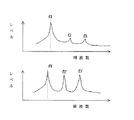
三重モードフィルタの周波数調整法については、例えば特開平7−189884号公報に公開されている。図4(b)において端子T3とTcとを短絡して、T1−Tcの1端子対共振子とした場合の共振周波数を低い周波数からf1、f2、f3とする。ここで、水晶基板31の平面度及び平行度が理想的であり、電極対32−33、34−35、36−37の質量負荷が同一であるならば、図5の上段に示すような共振特性を呈する。そこで、図5の右端に示すように相並んだ3電極の両端の電極にのみに質量を付加すると、その共振特性は下段に示すような共振特性となる。即ち、f2の周波数変動がf1、f3に比べて大きく移動する。周波数f1と周波数f3の周波数移動量は大略同じで周波数差(f3’−f1’)は(f3−f1)とほぼ同じであるが、周波数f2の変化量は大きくなり、周波数差(f2’−f1’)は(f2−f1)と比べて大幅に小さくなる。
これは、反対称零次モードA0(共振周波数f2)の振動変位は電極34の中央で0となり、電極32、36のほぼ中央で最大の変位を呈する。周知のように、振動体の振動部分に質量を付加する際、振動変位が最大である位置に付加すると周波数変化量が最大になるからである。
また、逆に両端の電極の質量を電子ビーム等で一様に削取ると(f3’−f1’)はほぼ一定の状態で、周波数差(f2’−f1’)は(f2−f1)と比べて増大することになる。
【0004】
次に、図6の右端に示すように相並んだ3電極のうち、中央の電極34にのみ質量を付加すると、周波数変化量の大きいモードは対称零次モードS0(周波数f1)であり、次が対称1次モードS1(周波数f3)、周波数の変動の少ないモードは反対称零次モードA0(f2)である。従って三重モードフィルタの中央の電極34に質量を付加し周波数を低下させると、反対称零次モードA0の周波数変動量が小さいため、周波数差(f3’−f1 ’)をほぼ一定に保持したまま周波数差(f3’−f2’)を減少させることが出来る。逆に電極34の質量を削り取りと周波数差(f3’−f2’)を増大させることができる。
【0005】
また、三重モードフィルタのいずれの電極に質量を付加した場合でも程度の差はあれ全体の周波数に影響するため、各々の周波数配列を崩さず全体の周波数を低下する方法が必要であるが、電極33、35、37の全体に蒸着などの方法を用いて質量を付加すれば、3つの周波数を並行移動させることができる。
【0006】
【発明が解決しようとする課題】
しかしながら、上記したような三重モードフィルタの周波数調整法は、従来の平板状の水晶基板を用いた三重モードフィルタには適用可能であったが、図7に断面図を示すような、水晶基板40にエッチング等の手段を用いて凹陥部41を形成した高周波圧電基板に、3つの電極42、43、44を近接配置し、凹陥側に全面電極45を配設した高周波三重モードフィルタには、次に述べる理由で適用できないという問題があった。即ち、凹陥部41の薄肉部(振動部)の板厚は高周波を得るため十数ミクロンと極めて薄く加工する必要があり、図8、9の上段に示すように、平行度あるいは平面度が良好ではない場合が多い。例えば、図8に示すように、図中の左端から右端にかけて基板の厚みが次第に薄くなるような基板に、電極42、43、44と全面電極45を付着し、電極43、44、45を短絡して、T1−Tcからみた1端子対共振子の共振特性を測定すると、例えば図8の下段に示すような特性となる。つまり、各電極対42−45、43−45、44−45の共振周波数が大幅に異なるために、各電極間に生じる結合が極めて弱くなり、図8に示すような振動部の形状の場合には、駆動する電極42−45により対称零次モードS0(共振周波数f1)が強く励振されるが、反対称零次モードA0(共振周波数f2)、対称1次モードS1(共振周波数f3)の共振レベルは極めて小さくなり、場合によっては他のモードによる共振に隠れて検出できないこともある。
【0007】
逆に、図9の上段に示すように基板の厚みが図中左端から右端にかけて次第に厚くなる場合、端子T1−Tc側から駆動した共振特性は、同図の下段に示すように各電極間の結合が弱いために対称1次モード(S1)は強く励振されるが、他の対称零次モードS0(共振周波数f1)、反対称零次モードA0(共振周波数f2)の共振レベルは極めて小さくなる。
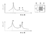
そこで、図10の上段左のような共振特性の場合に、対称1次モードS1(f3)の共振レベルを大きくすべく電極44に質量を付加すると、反対称零次モードA0(f2)が大きく周波数移動することになり、図10の下段に示すように対称零次モードS0(f1)の共振と反対称零次モードA0(f2)の共振周波数が接近するようになる。また、図11の上段右に示すように、電極43、44に質量を付加すると、下段に示すように反対称零次モードA0(f2)が対称1次モードS1(f3)と近接するようになり、高周波三重モードフィルタの周波数調整に従来の三重モードフィルタの周波数調整法が適用できないという問題があった。
本発明は上記問題を解決するためになされたものであって、高周波圧電基板の平面度、平行度が悪い場合でも高周波三重モードフィルタの周波数調整を可能とし、所定のフィルタ特性に調整できる手法を提供することを目的とする。
【0008】
【課題を解決するための手段】
上記目的を達成するために本発明に係る三重モード圧電フィルタの製造方法は、一方の主面上に凹陥部を形成した圧電基板の平坦面側に3つの電極を配置すると共に、凹陥面側に全面電極を施した三重モード圧電フィルタの周波数を調整する工程において、前記3つの電極の一方の端の電極と前記全面電極とを駆動電極とし、他の電極を全面電極と短絡した1端子対共振子が呈する共振特性に応じて、中央の電極および前記端の電極に質量を同時に付加して周波数調整するときの前記質量は、前記中央の電極よりも前記端の電極の方が多いことを特徴とする。また、三重モード圧電フィルタの製造方法において、さらに、前記周波数を調整する工程は、孔が開いたマスクを前記平坦面側に被せて、前記中央および前記端の電極に質量を負荷する工程を有し、前記孔は、前記中央の電極を露出する領域よりも前記端の電極を露出する領域の方が広いことを特徴とする。そして、上記の周波数を調整する工程を含む製造方法によって、三重モード圧電フィルタは製造される。
【0009】
【発明の実施の形態】
以下本発明を図面に示した実施の形態に基づいて詳細に説明する。
図1(a)は本発明に係る三重モードフィルタの構成を示す平面図であって、水晶基板1の一方の主面の一部をエッチング等の手段により、振動部となる凹陥部2を形成すると共に、該凹陥面に全面電極3を施し、端子Tcと接続する。一方、平坦側に3つの電極4、5、6を近接して配置すると共に、該電極4、5、6から水晶基板1の端部に向けてリード電極を延在し、それぞれ端子T1,T2、T3と接続して高周波三重モードフィルタを構成する。
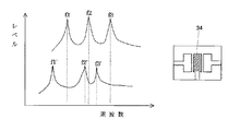
図1(b)は三重モードフィルタとして機能させるように各電極を接続した場合であり、端子T1−Tc、T3−Tcにそれぞれ適当な終端を施すことによりバンドパスフィルタとして作用する。図1(c)は本発明になる三角形状、矩形状に孔を開けた周波数調整用のマスク7a、7bを三重モードフィルタ素子に被せて周波数を行う場合の状態を示す図で、端の電極6上にはマスク7bをとおしてほぼ全面に質量が付加されるが、中央の電極5上はマスク7aをとおして電極5の一部にのみ質量が付加されるようになる。
【0010】
本発明の特徴は、従来のように電極6(電極4)、あるいは電極5、6(電極4、5)のようにそれぞれの電極にほぼ等面積に質量付加するのではなく、電極6(電極4)のほぼ全面、電極5の一部、例えば電極の1/4に質量付加することにより、対称零次モード(f1)、反対称零次モード(f2)、対称1次モード(f3)の共振周波数は互いに接近することなく、しかもその共振レベルが増大するようになる。従って、各モードの周波数とレベルを確認しながら周波数を調整することができるようになったことである。
【0011】
図2は本発明になる三角形状の周波数調整用マスクを用いて、三重モードフィルタの周波数調整を行った際の周波数特性を示す図である。始めに、端子T1−Tcから三重モードフィルタ素子の周波数特性を測定したとき図2の上段に示すような場合とする。電極5、6上に図1(c)に示すようなマスクで覆い、質量付加を始めると図2下段に示すように各モードのレベルが大きくなり、共振周波数の測定が容易になる。このように各モードのレベルが大きくなると、各モードの共振周波数を精度良く測定できるようになり、その後は従来の調整法にて所望の周波数に調整すればよい。
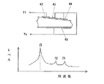
図3は130MHz帯の高周波三重モードフィルタを本発明になる周波数調整用マスクを用いて周波数調整し、1端子対共振子として測定した例である。
【0012】
以上では圧電基板に水晶を用いた三重モードフィルタの例を説明したが、本発明はこれのみに限ることなく他の圧電基板、四硼酸リチウム、タンタル酸リチウム、ランガサイト等の圧電基板を用いた三重モードフィルタに適用してもよい。
また、周波数調整用マスクの形状としては必ずしも三角形状である必要はなく、中央の電極と端の電極とに付着する質量付加を異なるようにした形状であればよい。
また、上記説明は質量を付加して三重モードフィルタの周波数調整法を説明したが、電極膜を薄く削り取るように調整してもよい。この場合も中央の電極と、一方の端の電極とを同時に削り取る量を異なるようにすればよい。
【0013】
【発明の効果】
本発明は、以上説明したように構成したので、請求項1に記載の発明は高周波三重モードフィルタの周波数調整法が、従来の試行錯誤による調整法に比べて遙かに優れた効果を表す。請求項2に記載の発明は、各電極に余分な質量付加を行うことがないので、スプリアス等の少ないフィルタが得られるという効果がある。
【図面の簡単な説明】
【図1】(a)は本発明に係る三重モードフィルタの構成を示す平面図、(b)は各電極の接続法を示す図、(c)は三重モードフィルタ素子に周波数調整用マスクを被せた場合の平面図である。
【図2】 周波数調整前後の周波数特性を示す図である。
【図3】各電極の周波数調整が完了した後の周波数特性を示す図である。
【図4】(a)は従来の三重モードフィルタの構成を示す平面図、(b)はフィルタとして機能させる場合の各電極の接続状態を示す図である。
【図5】従来の三重モードフィルタの周波数調整法を示す図である。
【図6】従来の三重モードフィルタの周波数調整法を示す図である。
【図7】従来の高周波三重モードフィルタの構成を示す断面図である。
【図8】圧電基板の振動部が一様でない場合(図中左から右にかけて厚みが薄くなる)の周波数特性である。
【図9】圧電基板の振動部が一様でない場合(図中左から右にかけて厚みが厚くなる)の周波数特性である。
【図10】第3電極への質量付加と周波数特性との関係を示す図である。
【図11】第2、第3電極への質量付加と周波数特性との関係を示す図である。
【符号の説明】
1・・圧電基板
2・・凹陥部
3・・全面電極
4、5、6・・電極
T1、T2、T3、Tc・・端子
7・・周波数調整用マスク
8、9・・付加された質量[0001]
BACKGROUND OF THE INVENTION
The present invention relates to a high-frequency triple mode piezoelectric filter and a frequency adjustment method thereof, and more particularly to an improvement of a frequency adjustment method of a high-frequency triple mode filter.
[0002]
[Prior art]
In recent years, high-frequency piezoelectric devices, particularly multimode piezoelectric filters using a quartz substrate (hereinafter referred to as multimode filters) are small, light and robust, and have excellent frequency temperature characteristics. Widely used.
FIG. 4A is a plan view showing the configuration of a conventional triple mode filter, and three pairs of electrodes 32-33, 34-35, and 36-37 facing each other are arranged close to each other on the main surface of the
It is well known that the
[0003]
A method for adjusting the frequency of the triple mode filter is disclosed in, for example, Japanese Patent Laid-Open No. 7-189884. In FIG. 4B, when the terminals T3 and Tc are short-circuited to form a one-terminal pair resonator of T1-Tc, the resonance frequencies are set to f1, f2, and f3 from a low frequency. Here, if the flatness and parallelism of the
This is because the vibration displacement of the antisymmetric zero-order mode A 0 (resonance frequency f2) is 0 at the center of the
Conversely, if the masses of the electrodes at both ends are evenly scraped with an electron beam or the like, (f3′−f1 ′) is almost constant and the frequency difference (f2′−f1 ′) is (f2−f1). It will increase in comparison.
[0004]
Next, when mass is added only to the
[0005]
In addition, even if mass is added to any electrode of the triple mode filter, it affects the overall frequency to some extent, so a method for lowering the overall frequency without breaking each frequency array is necessary. If mass is added to the whole 33, 35, 37 using a method such as vapor deposition, the three frequencies can be moved in parallel.
[0006]
[Problems to be solved by the invention]
However, the frequency adjustment method of the triple mode filter as described above was applicable to a triple mode filter using a conventional flat plate crystal substrate, but the
[0007]
Conversely, when the thickness of the substrate gradually increases from the left end to the right end in the figure as shown in the upper part of FIG. 9, the resonance characteristics driven from the terminal T1-Tc side are between the electrodes as shown in the lower part of the figure. Since the coupling is weak, the symmetric first-order mode (S 1 ) is strongly excited, but the resonance levels of the other symmetric zero-order mode S 0 (resonance frequency f1) and anti-symmetric zero-order mode A 0 (resonance frequency f2) are Extremely small.
Therefore, in the case of the resonance characteristics as shown in the upper left of FIG. 10, if mass is added to the
The present invention has been made in order to solve the above-described problem, and it is possible to adjust the frequency of the high-frequency triple mode filter even when the flatness and parallelism of the high-frequency piezoelectric substrate are poor, and to adjust the frequency to a predetermined filter characteristic. The purpose is to provide.
[0008]
[Means for Solving the Problems]
In order to achieve the above object, a method of manufacturing a triple mode piezoelectric filter according to the present invention includes three electrodes disposed on a flat surface side of a piezoelectric substrate having a recessed portion formed on one main surface, and on the recessed surface side. In the step of adjusting the frequency of the triple mode piezoelectric filter with full-surface electrodes, one terminal pair resonance in which the electrode at one end of the three electrodes and the full-surface electrode are used as drive electrodes and the other electrodes are short-circuited with the full-surface electrodes. According to the resonance characteristics exhibited by the child , the mass when the frequency is adjusted by simultaneously adding mass to the center electrode and the end electrode is larger in the end electrode than in the center electrode. And In the method of manufacturing a triple mode piezoelectric filter, the step of adjusting the frequency further includes a step of placing a mask with a hole on the flat surface side and applying a mass to the center and end electrodes. The hole is wider in a region exposing the end electrode than in a region exposing the central electrode. And a triple mode piezoelectric filter is manufactured by the manufacturing method including the process of adjusting said frequency.
[0009]
DETAILED DESCRIPTION OF THE INVENTION
Hereinafter, the present invention will be described in detail based on embodiments shown in the drawings.
FIG. 1A is a plan view showing a configuration of a triple mode filter according to the present invention, in which a concave portion 2 serving as a vibration portion is formed on a part of one main surface of a quartz substrate 1 by means of etching or the like. At the same time, the
FIG. 1B shows a case where the respective electrodes are connected so as to function as a triple mode filter. The terminals T1-Tc and T3-Tc function as bandpass filters by providing appropriate terminations. FIG. 1 (c) is a diagram showing a state in which the frequency adjustment is performed by covering the triple mode filter element with
[0010]
The feature of the present invention is that the mass of the electrodes 6 (electrodes 4) or the
[0011]
FIG. 2 is a diagram showing frequency characteristics when the frequency adjustment of the triple mode filter is performed using the triangular frequency adjustment mask according to the present invention. First, when the frequency characteristic of the triple mode filter element is measured from the terminal T1-Tc, the case shown in the upper part of FIG. When the
FIG. 3 shows an example in which a 130 MHz band high-frequency triple mode filter is frequency-adjusted using a frequency-adjusting mask according to the present invention and measured as a one-terminal-pair resonator.
[0012]
In the above, an example of a triple mode filter using crystal as a piezoelectric substrate has been described. However, the present invention is not limited to this, and other piezoelectric substrates, such as piezoelectric substrates such as lithium tetraborate, lithium tantalate, and langasite are used. You may apply to a triple mode filter.
Further, the shape of the frequency adjustment mask is not necessarily a triangular shape, and may be a shape in which the mass addition attached to the center electrode and the end electrode is different.
In the above description, the method of adjusting the frequency of the triple mode filter by adding mass has been described. However, the electrode film may be adjusted to be thinly cut. In this case as well, the amount of the central electrode and the electrode at one end may be scraped simultaneously.
[0013]
【The invention's effect】
Since the present invention is configured as described above, according to the first aspect of the present invention, the frequency adjustment method of the high-frequency triple mode filter exhibits an effect far superior to the conventional adjustment method based on trial and error. According to the second aspect of the present invention, since no extra mass is added to each electrode, a filter with less spurious and the like can be obtained.
[Brief description of the drawings]
FIG. 1A is a plan view showing a configuration of a triple mode filter according to the present invention, FIG. 1B is a diagram showing a connection method of each electrode, and FIG. 1C is a frequency adjustment mask on the triple mode filter element. FIG.
FIG. 2 is a diagram illustrating frequency characteristics before and after frequency adjustment.
FIG. 3 is a diagram illustrating frequency characteristics after frequency adjustment of each electrode is completed.
4A is a plan view showing a configuration of a conventional triple mode filter, and FIG. 4B is a diagram showing a connection state of each electrode when functioning as a filter.
FIG. 5 is a diagram illustrating a frequency adjustment method of a conventional triple mode filter.
FIG. 6 is a diagram illustrating a frequency adjustment method of a conventional triple mode filter.
FIG. 7 is a cross-sectional view showing a configuration of a conventional high-frequency triple mode filter.
FIG. 8 shows frequency characteristics when the vibration part of the piezoelectric substrate is not uniform (thickness decreases from left to right in the figure).
FIG. 9 shows frequency characteristics when the vibration part of the piezoelectric substrate is not uniform (thickness increases from left to right in the figure).
FIG. 10 is a diagram showing a relationship between mass addition to a third electrode and frequency characteristics.
FIG. 11 is a diagram showing the relationship between mass addition to the second and third electrodes and frequency characteristics.
[Explanation of symbols]
1 .. Piezoelectric substrate 2 .. Recessed
Claims (2)
Priority Applications (1)
| Application Number | Priority Date | Filing Date | Title |
|---|---|---|---|
| JP2001013392A JP4701504B2 (en) | 2001-01-22 | 2001-01-22 | Manufacturing method of triple mode piezoelectric filter |
Applications Claiming Priority (1)
| Application Number | Priority Date | Filing Date | Title |
|---|---|---|---|
| JP2001013392A JP4701504B2 (en) | 2001-01-22 | 2001-01-22 | Manufacturing method of triple mode piezoelectric filter |
Publications (3)
| Publication Number | Publication Date |
|---|---|
| JP2002217663A JP2002217663A (en) | 2002-08-02 |
| JP2002217663A5 JP2002217663A5 (en) | 2008-03-27 |
| JP4701504B2 true JP4701504B2 (en) | 2011-06-15 |
Family
ID=18880249
Family Applications (1)
| Application Number | Title | Priority Date | Filing Date |
|---|---|---|---|
| JP2001013392A Expired - Fee Related JP4701504B2 (en) | 2001-01-22 | 2001-01-22 | Manufacturing method of triple mode piezoelectric filter |
Country Status (1)
| Country | Link |
|---|---|
| JP (1) | JP4701504B2 (en) |
Families Citing this family (6)
| Publication number | Priority date | Publication date | Assignee | Title |
|---|---|---|---|---|
| JP4039322B2 (en) | 2002-07-23 | 2008-01-30 | 株式会社村田製作所 | Piezoelectric filter, duplexer, composite piezoelectric resonator and communication device, and frequency adjustment method of piezoelectric filter |
| CN101069344B (en) * | 2004-12-07 | 2010-05-12 | 松下电器产业株式会社 | Thin film elastic wave resonator, and filter and communication equipment using the resonator |
| US9559398B2 (en) | 2011-08-23 | 2017-01-31 | Mesaplex Pty Ltd. | Multi-mode filter |
| US9406988B2 (en) | 2011-08-23 | 2016-08-02 | Mesaplexx Pty Ltd | Multi-mode filter |
| US20140097913A1 (en) | 2012-10-09 | 2014-04-10 | Mesaplexx Pty Ltd | Multi-mode filter |
| US9325046B2 (en) | 2012-10-25 | 2016-04-26 | Mesaplexx Pty Ltd | Multi-mode filter |
Citations (3)
| Publication number | Priority date | Publication date | Assignee | Title |
|---|---|---|---|---|
| JPS53113451A (en) * | 1977-03-15 | 1978-10-03 | Fujitsu Ltd | Zone adjustment method for piezoelectric filter |
| JPH0918266A (en) * | 1995-07-03 | 1997-01-17 | Toyo Commun Equip Co Ltd | Frequency adjustment method for triple mode piezoelectric filter |
| JP2000341067A (en) * | 1999-05-28 | 2000-12-08 | Daishinku Corp | Method and device for adjusting frequency of piezoelectric device |
-
2001
- 2001-01-22 JP JP2001013392A patent/JP4701504B2/en not_active Expired - Fee Related
Patent Citations (3)
| Publication number | Priority date | Publication date | Assignee | Title |
|---|---|---|---|---|
| JPS53113451A (en) * | 1977-03-15 | 1978-10-03 | Fujitsu Ltd | Zone adjustment method for piezoelectric filter |
| JPH0918266A (en) * | 1995-07-03 | 1997-01-17 | Toyo Commun Equip Co Ltd | Frequency adjustment method for triple mode piezoelectric filter |
| JP2000341067A (en) * | 1999-05-28 | 2000-12-08 | Daishinku Corp | Method and device for adjusting frequency of piezoelectric device |
Also Published As
| Publication number | Publication date |
|---|---|
| JP2002217663A (en) | 2002-08-02 |
Similar Documents
| Publication | Publication Date | Title |
|---|---|---|
| US4456850A (en) | Piezoelectric composite thin film resonator | |
| US7170215B2 (en) | Electronic component and method for manufacturing the same | |
| US6441539B1 (en) | Piezoelectric resonator | |
| US20050248238A1 (en) | Thin film piezoelectric resonator, thin film piezoelectric device, and manufacturing method thereof | |
| US7320164B2 (en) | Method of manufacturing an electronic component | |
| AU2021407849B2 (en) | Frequency-tunable film bulk acoustic resonator and preparation method therefor | |
| GB2418549A (en) | Upright or upstanding piezoelectric resonator | |
| JP4701504B2 (en) | Manufacturing method of triple mode piezoelectric filter | |
| JP2003229743A (en) | Piezoelectric filter, communication apparatus and method for manufacturing the piezoelectric filter | |
| US6492759B1 (en) | Piezoelectric resonator and a filter | |
| US20240022227A1 (en) | Acoustic resonator and filter device with balanced chirping | |
| JPS62266906A (en) | Piezoelectric thin film resonator | |
| JP2003037476A (en) | High-frequency piezoelectric filter | |
| JP2000312130A (en) | Piezoelectric device, manufacture thereof and mobile communication unit employing them | |
| JPS61218214A (en) | Piezoelectric thin film resonator | |
| CN214851161U (en) | Frequency-adjustable film bulk acoustic resonator | |
| EP0594117B1 (en) | Piezoelectric filter and its production method | |
| JP3468160B2 (en) | Frequency adjustment method for piezoelectric device and frequency adjustment device for piezoelectric device | |
| JP3255456B2 (en) | Manufacturing method of ultra-thin piezoelectric resonator element plate | |
| JP3552056B2 (en) | Multi-mode piezoelectric filter element | |
| JPS63120508A (en) | Manufacture of piezoelectric resonator | |
| KR100446258B1 (en) | Bulk Acoustic Wave Device for High Frequency Using Piezoelectric Single Crystal and Process of The Same | |
| CN118282348A (en) | Acoustic resonator with symmetrical coating material for improved coupling | |
| JP2000151354A (en) | Piezoelectric filter | |
| JP2004032276A (en) | Surface acoustic wave device and method for regulating its frequency |
Legal Events
| Date | Code | Title | Description |
|---|---|---|---|
| A521 | Written amendment |
Free format text: JAPANESE INTERMEDIATE CODE: A523 Effective date: 20080108 |
|
| A621 | Written request for application examination |
Free format text: JAPANESE INTERMEDIATE CODE: A621 Effective date: 20080108 |
|
| RD03 | Notification of appointment of power of attorney |
Free format text: JAPANESE INTERMEDIATE CODE: A7423 Effective date: 20080208 |
|
| A131 | Notification of reasons for refusal |
Free format text: JAPANESE INTERMEDIATE CODE: A131 Effective date: 20101221 |
|
| A521 | Written amendment |
Free format text: JAPANESE INTERMEDIATE CODE: A523 Effective date: 20110119 |
|
| A01 | Written decision to grant a patent or to grant a registration (utility model) |
Free format text: JAPANESE INTERMEDIATE CODE: A01 Effective date: 20110208 |
|
| A61 | First payment of annual fees (during grant procedure) |
Free format text: JAPANESE INTERMEDIATE CODE: A61 Effective date: 20110221 |
|
| FPAY | Renewal fee payment (event date is renewal date of database) |
Free format text: PAYMENT UNTIL: 20140318 Year of fee payment: 3 |
|
| S111 | Request for change of ownership or part of ownership |
Free format text: JAPANESE INTERMEDIATE CODE: R313111 |
|
| FPAY | Renewal fee payment (event date is renewal date of database) |
Free format text: PAYMENT UNTIL: 20140318 Year of fee payment: 3 |
|
| R371 | Transfer withdrawn |
Free format text: JAPANESE INTERMEDIATE CODE: R371 |
|
| FPAY | Renewal fee payment (event date is renewal date of database) |
Free format text: PAYMENT UNTIL: 20140318 Year of fee payment: 3 |
|
| S111 | Request for change of ownership or part of ownership |
Free format text: JAPANESE INTERMEDIATE CODE: R313111 |
|
| FPAY | Renewal fee payment (event date is renewal date of database) |
Free format text: PAYMENT UNTIL: 20140318 Year of fee payment: 3 |
|
| R350 | Written notification of registration of transfer |
Free format text: JAPANESE INTERMEDIATE CODE: R350 |
|
| S531 | Written request for registration of change of domicile |
Free format text: JAPANESE INTERMEDIATE CODE: R313531 |
|
| R350 | Written notification of registration of transfer |
Free format text: JAPANESE INTERMEDIATE CODE: R350 |
|
| LAPS | Cancellation because of no payment of annual fees |


