JP4664142B2 - Stage equipment - Google Patents
Stage equipment Download PDFInfo
- Publication number
- JP4664142B2 JP4664142B2 JP2005211724A JP2005211724A JP4664142B2 JP 4664142 B2 JP4664142 B2 JP 4664142B2 JP 2005211724 A JP2005211724 A JP 2005211724A JP 2005211724 A JP2005211724 A JP 2005211724A JP 4664142 B2 JP4664142 B2 JP 4664142B2
- Authority
- JP
- Japan
- Prior art keywords
- axis
- support base
- holding member
- stage
- supported
- Prior art date
- Legal status (The legal status is an assumption and is not a legal conclusion. Google has not performed a legal analysis and makes no representation as to the accuracy of the status listed.)
- Active
Links
Images


Classifications
-
- H—ELECTRICITY
- H01—ELECTRIC ELEMENTS
- H01L—SEMICONDUCTOR DEVICES NOT COVERED BY CLASS H10
- H01L21/00—Processes or apparatus adapted for the manufacture or treatment of semiconductor or solid state devices or of parts thereof
- H01L21/67—Apparatus specially adapted for handling semiconductor or electric solid state devices during manufacture or treatment thereof; Apparatus specially adapted for handling wafers during manufacture or treatment of semiconductor or electric solid state devices or components ; Apparatus not specifically provided for elsewhere
- H01L21/68—Apparatus specially adapted for handling semiconductor or electric solid state devices during manufacture or treatment thereof; Apparatus specially adapted for handling wafers during manufacture or treatment of semiconductor or electric solid state devices or components ; Apparatus not specifically provided for elsewhere for positioning, orientation or alignment
- H01L21/682—Mask-wafer alignment
-
- G—PHYSICS
- G03—PHOTOGRAPHY; CINEMATOGRAPHY; ANALOGOUS TECHNIQUES USING WAVES OTHER THAN OPTICAL WAVES; ELECTROGRAPHY; HOLOGRAPHY
- G03F—PHOTOMECHANICAL PRODUCTION OF TEXTURED OR PATTERNED SURFACES, e.g. FOR PRINTING, FOR PROCESSING OF SEMICONDUCTOR DEVICES; MATERIALS THEREFOR; ORIGINALS THEREFOR; APPARATUS SPECIALLY ADAPTED THEREFOR
- G03F7/00—Photomechanical, e.g. photolithographic, production of textured or patterned surfaces, e.g. printing surfaces; Materials therefor, e.g. comprising photoresists; Apparatus specially adapted therefor
- G03F7/70—Microphotolithographic exposure; Apparatus therefor
- G03F7/70691—Handling of masks or workpieces
- G03F7/70716—Stages
-
- G—PHYSICS
- G03—PHOTOGRAPHY; CINEMATOGRAPHY; ANALOGOUS TECHNIQUES USING WAVES OTHER THAN OPTICAL WAVES; ELECTROGRAPHY; HOLOGRAPHY
- G03F—PHOTOMECHANICAL PRODUCTION OF TEXTURED OR PATTERNED SURFACES, e.g. FOR PRINTING, FOR PROCESSING OF SEMICONDUCTOR DEVICES; MATERIALS THEREFOR; ORIGINALS THEREFOR; APPARATUS SPECIALLY ADAPTED THEREFOR
- G03F7/00—Photomechanical, e.g. photolithographic, production of textured or patterned surfaces, e.g. printing surfaces; Materials therefor, e.g. comprising photoresists; Apparatus specially adapted therefor
- G03F7/70—Microphotolithographic exposure; Apparatus therefor
- G03F7/70691—Handling of masks or workpieces
- G03F7/70758—Drive means, e.g. actuators, motors for long- or short-stroke modules or fine or coarse driving
-
- H—ELECTRICITY
- H01—ELECTRIC ELEMENTS
- H01L—SEMICONDUCTOR DEVICES NOT COVERED BY CLASS H10
- H01L21/00—Processes or apparatus adapted for the manufacture or treatment of semiconductor or solid state devices or of parts thereof
- H01L21/67—Apparatus specially adapted for handling semiconductor or electric solid state devices during manufacture or treatment thereof; Apparatus specially adapted for handling wafers during manufacture or treatment of semiconductor or electric solid state devices or components ; Apparatus not specifically provided for elsewhere
- H01L21/683—Apparatus specially adapted for handling semiconductor or electric solid state devices during manufacture or treatment thereof; Apparatus specially adapted for handling wafers during manufacture or treatment of semiconductor or electric solid state devices or components ; Apparatus not specifically provided for elsewhere for supporting or gripping
- H01L21/687—Apparatus specially adapted for handling semiconductor or electric solid state devices during manufacture or treatment thereof; Apparatus specially adapted for handling wafers during manufacture or treatment of semiconductor or electric solid state devices or components ; Apparatus not specifically provided for elsewhere for supporting or gripping using mechanical means, e.g. chucks, clamps or pinches
- H01L21/68714—Apparatus specially adapted for handling semiconductor or electric solid state devices during manufacture or treatment thereof; Apparatus specially adapted for handling wafers during manufacture or treatment of semiconductor or electric solid state devices or components ; Apparatus not specifically provided for elsewhere for supporting or gripping using mechanical means, e.g. chucks, clamps or pinches the wafers being placed on a susceptor, stage or support
Landscapes
- General Physics & Mathematics (AREA)
- Physics & Mathematics (AREA)
- Engineering & Computer Science (AREA)
- Microelectronics & Electronic Packaging (AREA)
- Manufacturing & Machinery (AREA)
- Computer Hardware Design (AREA)
- Condensed Matter Physics & Semiconductors (AREA)
- Power Engineering (AREA)
- Container, Conveyance, Adherence, Positioning, Of Wafer (AREA)
- Exposure Of Semiconductors, Excluding Electron Or Ion Beam Exposure (AREA)
- Exposure And Positioning Against Photoresist Photosensitive Materials (AREA)
- Details Of Measuring And Other Instruments (AREA)
- Machine Tool Units (AREA)
Description
本発明はステージ装置に係り、特に対象物を保持する保持部材をZ軸方向に昇降させる際の微動制御を安定的に行なえるよう構成されたステージ装置に関する。 The present invention relates to a stage apparatus, and more particularly to a stage apparatus configured to be able to stably perform fine movement control when a holding member that holds an object is moved up and down in the Z-axis direction.
半導体装置製造の分野においては、様々なタイプのステージ装置が使用されている。例えば、電子ビーム露光装置に採用されるウエハ搭載用のステージ装置には、ウエハの搬送やチップ間移動時に動作する粗動制御と、数nm〜10nm程度の位置決めを行う微動制御とを組み合わせた制御方法が採用されている(例えば、特許文献1参照)。 In the field of semiconductor device manufacturing, various types of stage apparatuses are used. For example, in a stage device for mounting a wafer employed in an electron beam exposure apparatus, control that combines coarse movement control that operates during wafer transfer and chip-to-chip movement and fine movement control that performs positioning of several nanometers to 10 nm. A method is employed (see, for example, Patent Document 1).
この種のステージ装置では、対象物としてのウエハが搬送されてウエハ保持部材(真空チャックまたは静電チャックを有する)に保持されると、露光装置の光学系に対するウエハの位置を高精度に位置決めするため、ウエハ保持部材をZ軸方向及びZ軸回りのθz方向に動作させてウエハの位置を調整する位置決め制御を行なうように構成されている。 In this type of stage apparatus, when a wafer as an object is conveyed and held on a wafer holding member (having a vacuum chuck or electrostatic chuck), the position of the wafer with respect to the optical system of the exposure apparatus is positioned with high accuracy. Therefore, the wafer holding member is moved in the Z-axis direction and the θz direction around the Z-axis to perform positioning control for adjusting the wafer position.
ステージ装置では、ウエハを撮像するためのCCDカメラの焦点距離(焦点深度)に合わせてウエハの高さ位置を微調整する一対のZ軸アクチュエータが周方向上180度間隔で配置されている。また、ウエハ保持部材は、XYステージ上に搭載された回動支持部材に支持されており、回動支持部材上にはベアリングによりθz方向に回動可能に支持された昇降支持部材が設けられている。そして、昇降支持部材の周縁部には、一対のZ軸アクチュエータが設けられており、且つ昇降支持部材の中央部分にはウエハ保持部材をZ軸方向に昇降可能にガイドするZ軸ガイド部が設けられている。
上記従来の構成では、ベアリングにより回動可能に支持された昇降支持部材に一対のZ軸アクチュエータが設けられているため、一対のZ軸アクチュエータの駆動力によりウエハ保持部材の高さ位置を調整する際にZ軸アクチュエータからの反力が昇降支持部材に作用する。従来は、昇降支持部材がベアリングにより回動可能に支持されているので、一対のZ軸アクチュエータからの2つの反力が異なる大きさであったり、あるいは2つの反力のタイミングがずれた場合には、ベアリングを支点として昇降支持部材が揺動するといった現象が現れる。 In the above conventional configuration, since the pair of Z-axis actuators are provided on the lifting support member that is rotatably supported by the bearing, the height position of the wafer holding member is adjusted by the driving force of the pair of Z-axis actuators. At that time, the reaction force from the Z-axis actuator acts on the lifting support member. Conventionally, since the elevating support member is rotatably supported by the bearing, the two reaction forces from the pair of Z-axis actuators have different sizes or the timing of the two reaction forces is deviated. The phenomenon that the elevating support member swings around the bearing as a fulcrum appears.
このような、Z軸アクチュエータからの反力による昇降支持部材の動作は、ウエハ保持部材に保持されたウエハと光学系との相対位置を精密に調整する際の誤差要因となる。一方、ウエハ保持部材をZ軸方向に粗動動作させたときは、駆動力が大きいので、その反力も大きくなる。そのため、昇降支持部材及び昇降支持部材が搭載されたXYステージが有する機械的な固有振動が誘発されるおそれがある。 Such an operation of the lifting support member due to the reaction force from the Z-axis actuator becomes an error factor when the relative position between the wafer held by the wafer holding member and the optical system is precisely adjusted. On the other hand, when the wafer holding member is coarsely moved in the Z-axis direction, since the driving force is large, the reaction force also increases. Therefore, there is a risk of inducing mechanical natural vibration of the elevating support member and the XY stage on which the elevating support member is mounted.
その場合、粗動制御の反力による昇降支持部材の振動が収束するまでの整定時間が長くなり、Z軸方向の粗動制御を行なった後のZ軸方向の微動制御が遅れるという問題が生じる。 In that case, the settling time until the vibration of the elevating support member is converged due to the reaction force of the coarse motion control becomes longer, and there is a problem that the fine motion control in the Z-axis direction after the coarse motion control in the Z-axis direction is delayed. .
そこで、本発明は上記課題を解決したステージ装置を提供することを目的とする。 Accordingly, an object of the present invention is to provide a stage apparatus that solves the above-described problems.
上記課題を解決するため、本発明は以下のような手段を有する。 In order to solve the above problems, the present invention has the following means.
請求項1記載の発明は、X,Y方向に移動するXYステージと、
前記XYステージをX方向に移動させるX方向リニアアクチュエータと、
前記XYステージをY方向に移動させるY方向リニアアクチュエータと、
前記XYステージ上に支持されたθz支持ベースと、
前記θz支持ベース上に支持されたベアリングと、
前記ベアリングによりZ軸回りに回動可能に支持された昇降支持部材と、
前記昇降支持部材のZ軸ガイド部により昇降可能に支持され、対象物を保持する保持部材と、
前記θz支持ベース上に支持され、周方向上の所定間隔に配されて前記保持部材をZ軸方向に昇降する一対のZ軸アクチュエータと、
前記θz支持ベース上に支持され、前記昇降支持部材及び前記保持部材をZ軸回りに回動させるθz駆動アクチュエータと、
を有することを特徴とする。
The invention according to claim 1 is an XY stage that moves in the X and Y directions;
An X-direction linear actuator that moves the XY stage in the X direction;
A Y-direction linear actuator for moving the XY stage in the Y direction;
A θz support base supported on the XY stage;
A bearing supported on the θz support base;
A lifting support member supported by the bearing so as to be rotatable about the Z axis ;
A holding member that is supported by the Z-axis guide portion of the elevating support member so as to be movable up and down, and holds an object;
A pair of Z-axis actuators supported on the θz support base and arranged at predetermined intervals in the circumferential direction to raise and lower the holding member in the Z-axis direction;
A θz drive actuator that is supported on the θz support base and rotates the elevating support member and the holding member about the Z axis;
It is characterized by having .
本発明によれば、XYステージ上に支持されたθz支持ベースと、θz支持ベース上に支持されたベアリングと、ベアリングによりZ軸回りに回動可能に支持された昇降支持部材と、昇降支持部材のZ軸ガイド部により昇降可能に支持され対象物を保持する保持部材と、θz支持ベース上に支持され周方向上の所定間隔に配されて保持部材をZ軸方向に昇降する一対のZ軸アクチュエータと、θz支持ベース上に支持され昇降支持部材及び前記保持部材をZ軸回りに回動させるθz駆動アクチュエータと、を有するため、Z軸アクチュエータが保持部材を駆動するときの反力が昇降支持部材よりも質量の大きいθz支持ベース及びXYステージで受けることになるので振動が発生しにくくなり、Z軸アクチュエータの反力による振動発生が防止され、粗動制御時に大きな駆動力を発生させる場合でも昇降支持部材に反力が作用しないので、昇降支持部材の振動を抑制して粗動動作後の整定時間を短縮して微動制御への影響を低減することができる。 According to the present invention, the θz support base supported on the XY stage, the bearing supported on the θz support base, the elevating support member supported rotatably about the Z axis by the bearing, and the elevating support member A holding member that is supported by the Z-axis guide portion so as to be movable up and down, and a pair of Z axes that are supported on the θz support base and arranged at predetermined intervals in the circumferential direction to raise and lower the holding member in the Z-axis direction Since there is an actuator and a θz drive actuator supported on the θz support base and rotating the holding member and the holding member around the Z axis , the reaction force when the Z axis actuator drives the holding member prevention therefore will receive in a large mass θz support base and the XY stage than members hardly vibration occurs, the vibration generated due to the reaction force of the Z-axis actuator Even if a large driving force is generated during coarse motion control, the reaction force does not act on the lifting support member, so the vibration of the lifting support member is suppressed and the settling time after coarse motion is shortened, which affects the fine motion control. Can be reduced.
以下、図面を参照して本発明を実施するための最良の形態について説明する。 The best mode for carrying out the present invention will be described below with reference to the drawings.
図1は本発明になるステージ装置の一実施例を示す縦断面図である。図2は図1に示すステージ装置の斜視図である。尚、図2においては、説明の便宜上、ウエハ12が載置されるウエハ保持部材14を省略してある。
FIG. 1 is a longitudinal sectional view showing an embodiment of a stage apparatus according to the present invention. FIG. 2 is a perspective view of the stage apparatus shown in FIG. In FIG. 2, the
図1及び図2に示されるように、ステージ装置10は、ウエハ12が載置されるウエハ保持部材(保持部材)14と、ウエハ保持部材14のZ軸部材16を昇降可能に支持するZ軸支持ベース(昇降支持部材)18と、ベアリング20を介してZ軸支持ベース18を回動可能に支持するθz支持ベース(回動支持部材)22と、θz支持ベース22が搭載されたXYテーブル24と、XYテーブル24が搭載されたYステージ26とを有する。
As shown in FIGS. 1 and 2, the
また、XYテーブル24は、内部に挿通されたYステージ26の延在方向に移動するように設けられており、Yステージ26には、X方向リニアスケール42、X方向リニアアクチュエータ44が搭載されている。さらに、Yステージ26の左右側面の外壁には、XYテーブル24に対するY方向の静圧パッド38が設けられている。また、XYテーブル24の左右両側の脚部下端には、石定盤46上を浮上するためのZ方向の静圧パッド48が設けられている。
The XY table 24 is provided so as to move in the extending direction of the
ウエハ保持部材14は、上面にウエハ12を吸着する真空チャックまたは静電チャック(図示せず)からなる吸着部14aと、吸着部14aが搭載された横架部材14bとを有する。また、横架部材14bの下面中央には、下方に突出するZ軸部材16と設けられている。このZ軸部材16は、θz方向に回動しないように横断面形状が非円形(例えば、正方形)に形成されている。
The
Z軸支持ベース18は、Z軸部材16が摺動可能に嵌合するZ軸ガイド部18aと、Z軸ガイド部18aの側面より水平方向に延在形成された円盤形状の鍔部18bとを有する。Z軸ガイド部18aは、内部にZ軸部材16が嵌合するガイド穴18cが設けられており、ガイド穴18cの横断面形状はZ軸部材16の横断面形状と同一形状(例えば、正方形)に形成されている。そのため、ウエハ保持部材14は、Z軸部材16がガイド穴18cに嵌合することでθz方向への回動が規制されている。
The Z-
Z軸支持ベース18には、ウエハ保持部材14の昇降位置を検出するZ軸方向エンコーダ28が設けられている。このZ軸方向エンコーダ28は、ウエハ保持部材14より側方に突出する被検出部14cの昇降位置を光学的または磁気的に検出するように構成されている。
The Z-
また、Z軸支持ベース18は、ベアリング20によりθz方向に回動可能に支持されており、θz駆動アクチュエータ32によりθz方向に駆動される。ベアリング20は、高い剛性と回転精度を有するクロスローラベアリングからなり、θz支持ベース22の中央に形成された円形凹部30に保持されている。
The Z-
θz駆動アクチュエータ32は、コイルとマグネットを組み合わせたボイスコイルモータからなり、ウエハ保持部材14に載置されたウエハ12のθz方向の位置が規定位置になるように微調整する駆動手段である。θz駆動アクチュエータ32の駆動力は、Z軸支持ベース18に印加されるため、ウエハ保持部材14はZ軸支持ベース18と一体的に回動してθz方向の位置を微調整される。また、θz支持ベース22には、θz駆動アクチュエータ32によりZ軸支持ベース18を回動させるときにθz方向の回動角度を検出するθz方向エンコーダ33が設けられている。このθz方向エンコーダ33は、Z軸支持ベース18より水平方向に突出する被検出部18dの回動位置に比例したパルス数をカウントしてθz方向の回動角度を出力する。
The
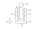
θz支持ベース22は、上記円形凹部30の外側に形成された平面部34上に一対のZ軸アクチュエータ36が設けられている。このZ軸アクチュエータ36は、前述したθz駆動アクチュエータ32と同様にボイスコイルモータからなり、平面部34上に取り付けられた固定子36aと、固定子36aに対して駆動される可動子36bとを有する。なお、固定子36aはマグネットを有し、可動子36bは、コイルを有するように構成されている。
The
また、本実施例では、Z軸アクチュエータ36の固定子36aがθz支持ベース22の平面部34上に固定されており、可動子36bがウエハ保持部材14の横架部材14bの両端に固定されている。さらに、一対のZ軸アクチュエータ36は、横架部材14bの両端をZ軸方向に昇降させるようにθz方向の周方向上180度間隔で配置されている。
In the present embodiment, the
従って、一対のZ軸アクチュエータ36は、ウエハ保持部材14の横架部材14bに対して同時に駆動力を付与するように制御され、Z軸支持ベース18の上面を傾けないように昇降させる。その際、Z軸アクチュエータ36の駆動力の反力は、θz支持ベース22で受けることになる。θz支持ベース22は、XYテーブル24に固定されているため、XYテーブル24と一体なものとして扱うことができるので、例えば、ウエハ保持部材14を上昇させる際には、θz支持ベース22の平面部34に対して下方に押圧するような反力が作用する場合でもθz支持ベース22及びXYテーブル24全体で反力を支えることができる。
Accordingly, the pair of Z-
従って、ステージ装置10では、Z軸アクチュエータ36の駆動力の反力による振動を防止できるので、例えば、Z軸アクチュエータ36を粗動制御してウエハ保持部材14を昇降動作した後にZ軸アクチュエータ36を微動制御する場合でも粗動制御により発生した振動が収束するのを待つ必要がなくなり、従来のものよりも微動制御の開始を早めることが可能になる。
Accordingly, the
ここで、Z軸アクチュエータ36の構成について説明する。図3はZ軸アクチュエータ36の側面図である。図4はZ軸アクチュエータ36の平面図である。
Here, the configuration of the Z-
図3及び図4に示されるように、Z軸アクチュエータ36の固定子36aは、コ字状に形成されたマグネットヨーク50の内壁に、板状に形成されたマグネット52が取り付けられている。マグネット52間には、可動子36bを構成する板状のコイル54が挿入されている。また、Z軸アクチュエータ36は、マグネットヨーク50が上方からみた場合もコ字状に形成されており、開口側からコイル54が挿入されるように組み合わされている。従って、Z軸アクチュエータ36は、マグネット52に対してコイル54がZ軸方向に昇降可能であり、且つθz方向にも回動可能に取り付けられている。
As shown in FIGS. 3 and 4, the
ウエハ保持部材14及びZ軸支持ベース18がθz方向に回動する際に、Z軸アクチュエータ36では、マグネット52に対してコイル54がθz方向に回動するため、上方からみると図4中一点鎖線で示すように傾いた状態になる。
When the
マグネット52とコイル54との隙間Sは、小さくするほど、磁束密度との関係から大きな駆動力を得られる。しかしながら、ステージ装置10では、Z軸アクチュエータ36のマグネット52及びコイル54を板状に形成してマグネット52とコイル54との対向面積を増大させてより大きな駆動力が得られるので、その分上記隙間Sをθz方向の回動に伴うコイル54の傾きよりも大きく設定することが可能になる。
The smaller the gap S between the
本実施例のマグネット52とコイル54との隙間Sは、通常のものよりも広く設定されているので、コイル54がθz方向に±2度回動してもマグネット52に接触することがない。よって、ステージ装置10においては、θz方向の角度調整範囲が拡大されている。
Since the gap S between the
上記実施例では、ウエハ保持部材14を昇降させる構成を一例として挙げたが、これに限らず、ウエハ以外の対象物が載置される保持部材を昇降させる構成のものにも本発明を適用できるのは、勿論である。
In the above embodiment, the configuration for raising and lowering the
上記実施例では、一対のZ軸アクチュエータ36の駆動力によりウエハ保持部材14を昇降させる構成を一例として挙げたが、これに限らず、2つ以上のZ軸アクチュエータ36を同時に駆動させてウエハ保持部材14を昇降させる構成としても良い。
In the above-described embodiment, the configuration in which the
また、上記実施例では、Z軸アクチュエータ36がボイスコイルモータにより構成された場合について説明したが、これに限らず、他のアクチュエータ(例えば、空圧シリンダなど)を用いても良い。
In the above embodiment, the case where the Z-
また、上記実施例では、θz支持ベース22がXYテーブル24に支持された構成を一例として挙げたが、例えば、θz支持ベース22をY方向のみに移動するYステージに直接搭載する構成のものにも適用することができるのは言うまでもない。
In the above-described embodiment, the configuration in which the
10 ステージ装置
14 ウエハ保持部材
18 Z軸支持ベース
20 θz支持ベース
24 XYテーブル
32 θz駆動アクチュエータ
36 Z軸アクチュエータ
50 マグネットヨーク
52 マグネット
54 コイル
10
Claims (1)
前記XYステージをX方向に移動させるX方向リニアアクチュエータと、
前記XYステージをY方向に移動させるY方向リニアアクチュエータと、
前記XYステージ上に支持されたθz支持ベースと、
前記θz支持ベース上に支持されたベアリングと、
前記ベアリングによりZ軸回りに回動可能に支持された昇降支持部材と、
前記昇降支持部材のZ軸ガイド部により昇降可能に支持され、対象物を保持する保持部材と、
前記θz支持ベース上に支持され、周方向上の所定間隔に配されて前記保持部材をZ軸方向に昇降する一対のZ軸アクチュエータと、
前記θz支持ベース上に支持され、前記昇降支持部材及び前記保持部材をZ軸回りに回動させるθz駆動アクチュエータと、
を有することを特徴とするステージ装置。 An XY stage moving in the X and Y directions;
An X-direction linear actuator that moves the XY stage in the X direction;
A Y-direction linear actuator for moving the XY stage in the Y direction;
A θz support base supported on the XY stage;
A bearing supported on the θz support base;
A lifting support member supported by the bearing so as to be rotatable about the Z axis ;
A holding member that is supported by the Z-axis guide portion of the elevating support member so as to be movable up and down, and holds an object;
A pair of Z-axis actuators supported on the θz support base and arranged at predetermined intervals in the circumferential direction to raise and lower the holding member in the Z-axis direction;
A θz drive actuator that is supported on the θz support base and rotates the elevating support member and the holding member about the Z axis;
Stage apparatus characterized by having a.
Priority Applications (6)
| Application Number | Priority Date | Filing Date | Title |
|---|---|---|---|
| JP2005211724A JP4664142B2 (en) | 2005-07-21 | 2005-07-21 | Stage equipment |
| TW095124692A TW200715357A (en) | 2005-07-21 | 2006-07-06 | Stage device |
| KR1020077028483A KR100909585B1 (en) | 2005-07-21 | 2006-07-20 | Stage device |
| PCT/JP2006/314356 WO2007010971A1 (en) | 2005-07-21 | 2006-07-20 | Stage device |
| CN2006800204661A CN101194214B (en) | 2005-07-21 | 2006-07-20 | Stage apparatus |
| US11/984,170 US7997567B2 (en) | 2005-07-21 | 2007-11-14 | Stage apparatus |
Applications Claiming Priority (1)
| Application Number | Priority Date | Filing Date | Title |
|---|---|---|---|
| JP2005211724A JP4664142B2 (en) | 2005-07-21 | 2005-07-21 | Stage equipment |
Publications (2)
| Publication Number | Publication Date |
|---|---|
| JP2007027659A JP2007027659A (en) | 2007-02-01 |
| JP4664142B2 true JP4664142B2 (en) | 2011-04-06 |
Family
ID=37668843
Family Applications (1)
| Application Number | Title | Priority Date | Filing Date |
|---|---|---|---|
| JP2005211724A Active JP4664142B2 (en) | 2005-07-21 | 2005-07-21 | Stage equipment |
Country Status (6)
| Country | Link |
|---|---|
| US (1) | US7997567B2 (en) |
| JP (1) | JP4664142B2 (en) |
| KR (1) | KR100909585B1 (en) |
| CN (1) | CN101194214B (en) |
| TW (1) | TW200715357A (en) |
| WO (1) | WO2007010971A1 (en) |
Families Citing this family (13)
| Publication number | Priority date | Publication date | Assignee | Title |
|---|---|---|---|---|
| JP4976922B2 (en) * | 2007-05-29 | 2012-07-18 | 株式会社オーク製作所 | Substrate transfer device |
| JP4750090B2 (en) * | 2007-09-14 | 2011-08-17 | 住友重機械工業株式会社 | Stage equipment |
| JP4917050B2 (en) * | 2008-01-23 | 2012-04-18 | 住友重機械工業株式会社 | Stage equipment |
| WO2010073514A1 (en) * | 2008-12-25 | 2010-07-01 | 株式会社アルバック | Method for manufacturing chuck plate for electrostatic chuck |
| US8084896B2 (en) * | 2008-12-31 | 2011-12-27 | Electro Scientific Industries, Inc. | Monolithic stage positioning system and method |
| JP5137218B1 (en) * | 2011-08-30 | 2013-02-06 | 株式会社ソディック | Machine Tools |
| CN102501226B (en) * | 2011-10-31 | 2014-02-19 | 西安理工大学 | Accurate rotation device for macro-micro driving deformation guide rail |
| CN104028944B (en) * | 2013-03-08 | 2016-08-10 | 鸿准精密模具(昆山)有限公司 | Apparatus for shaping and detent mechanism thereof |
| US10192773B2 (en) * | 2016-06-20 | 2019-01-29 | Nexperia B.V. | Semiconductor device positioning system and method for semiconductor device positioning |
| CN107081607B (en) * | 2017-02-22 | 2019-01-18 | 浙江江山福鑫工艺品有限公司 | A kind of workpieces processing machine table device |
| CN113606440B (en) * | 2021-08-05 | 2022-08-26 | 唐山师范学院 | Computer supporting table for Internet of things |
| WO2023243135A1 (en) * | 2022-06-15 | 2023-12-21 | 株式会社村田製作所 | Laminating device and laminating system |
| WO2024117283A1 (en) * | 2022-11-29 | 2024-06-06 | 이노로보틱스 주식회사 | Zt stage |
Citations (5)
| Publication number | Priority date | Publication date | Assignee | Title |
|---|---|---|---|---|
| JPH07111238A (en) * | 1993-10-12 | 1995-04-25 | Canon Inc | Self-weight support device |
| JPH07226354A (en) * | 1993-06-23 | 1995-08-22 | Canon Inc | Positioning device and manufacture of semiconductor device using this positioning device |
| JP2003028973A (en) * | 2001-07-13 | 2003-01-29 | Sumitomo Heavy Ind Ltd | Stage apparatus |
| JP2003028974A (en) * | 2001-07-13 | 2003-01-29 | Sumitomo Heavy Ind Ltd | Stage apparatus |
| JP2003167082A (en) * | 2001-11-30 | 2003-06-13 | Sumitomo Heavy Ind Ltd | Stage device |
Family Cites Families (8)
| Publication number | Priority date | Publication date | Assignee | Title |
|---|---|---|---|---|
| JP3164960B2 (en) | 1994-02-18 | 2001-05-14 | キヤノン株式会社 | Stage equipment |
| US5609332A (en) * | 1995-11-14 | 1997-03-11 | Hassell; Clayton | Device for lifting and holding cabinets |
| US5682658A (en) * | 1996-03-04 | 1997-11-04 | Utica Enterprises, Inc. | Rotary index table assembly |
| US6485248B1 (en) * | 2000-10-10 | 2002-11-26 | Applied Materials, Inc. | Multiple wafer lift apparatus and associated method |
| CN1588556A (en) * | 2004-07-30 | 2005-03-02 | 中国科学院上海光学精密机械研究所 | Five-degree-of-freedom precision positioning platform |
| US7869000B2 (en) * | 2004-11-02 | 2011-01-11 | Nikon Corporation | Stage assembly with lightweight fine stage and low transmissibility |
| JP4927338B2 (en) * | 2005-02-21 | 2012-05-09 | 住友重機械工業株式会社 | STAGE DEVICE, GANTRY TYPE STAGE DEVICE, AND STAGE DEVICE CONTROL METHOD |
| KR100667598B1 (en) * | 2005-02-25 | 2007-01-12 | 주식회사 아이피에스 | Apparatus for semiconductor process |
-
2005
- 2005-07-21 JP JP2005211724A patent/JP4664142B2/en active Active
-
2006
- 2006-07-06 TW TW095124692A patent/TW200715357A/en not_active IP Right Cessation
- 2006-07-20 CN CN2006800204661A patent/CN101194214B/en not_active Expired - Fee Related
- 2006-07-20 KR KR1020077028483A patent/KR100909585B1/en active IP Right Grant
- 2006-07-20 WO PCT/JP2006/314356 patent/WO2007010971A1/en active Application Filing
-
2007
- 2007-11-14 US US11/984,170 patent/US7997567B2/en active Active
Patent Citations (5)
| Publication number | Priority date | Publication date | Assignee | Title |
|---|---|---|---|---|
| JPH07226354A (en) * | 1993-06-23 | 1995-08-22 | Canon Inc | Positioning device and manufacture of semiconductor device using this positioning device |
| JPH07111238A (en) * | 1993-10-12 | 1995-04-25 | Canon Inc | Self-weight support device |
| JP2003028973A (en) * | 2001-07-13 | 2003-01-29 | Sumitomo Heavy Ind Ltd | Stage apparatus |
| JP2003028974A (en) * | 2001-07-13 | 2003-01-29 | Sumitomo Heavy Ind Ltd | Stage apparatus |
| JP2003167082A (en) * | 2001-11-30 | 2003-06-13 | Sumitomo Heavy Ind Ltd | Stage device |
Also Published As
| Publication number | Publication date |
|---|---|
| TWI307916B (en) | 2009-03-21 |
| US20080087791A1 (en) | 2008-04-17 |
| WO2007010971A1 (en) | 2007-01-25 |
| CN101194214A (en) | 2008-06-04 |
| KR100909585B1 (en) | 2009-07-24 |
| CN101194214B (en) | 2010-09-29 |
| JP2007027659A (en) | 2007-02-01 |
| US7997567B2 (en) | 2011-08-16 |
| TW200715357A (en) | 2007-04-16 |
| KR20080014989A (en) | 2008-02-15 |
Similar Documents
| Publication | Publication Date | Title |
|---|---|---|
| JP4664142B2 (en) | Stage equipment | |
| JP4384664B2 (en) | High-precision dynamic alignment mechanism for sample inspection and processing | |
| JP4782710B2 (en) | Stage equipment | |
| JP5102358B2 (en) | Stage with alignment function and processing apparatus provided with stage with alignment function | |
| TWI457193B (en) | Stage device | |
| JP2011119320A (en) | thetaZ DRIVE DEVICE AND STAGE DEVICE WITH THE SAME, AND INSPECTION DEVICE | |
| JP5504980B2 (en) | Wafer lift rotation mechanism, stage apparatus, and ion implantation apparatus | |
| JP5820559B2 (en) | High speed substrate placement equipment | |
| JP4877925B2 (en) | Stage equipment | |
| JP2007232648A (en) | Stage device | |
| JP4086651B2 (en) | Exposure apparatus and substrate holding apparatus | |
| KR102151930B1 (en) | Exposure device, method for manufacturing flat panel display, and method for manufacturing device | |
| JP2007019429A (en) | Stage equipment | |
| JPH11195578A (en) | Lapping plate supporter and aligner | |
| TWI356284B (en) | ||
| JP2007123860A (en) | Stage apparatus | |
| JP2007184193A (en) | Charged particle beam device | |
| JPH09275069A (en) | Stage device and aligner using the device | |
| JP2006170957A (en) | Tilted stage | |
| JP4324155B2 (en) | Exposure apparatus and device manufacturing method | |
| JPH10163300A (en) | Stage device | |
| JP2010199245A (en) | Wafer conveyance system equipped with prealigner device | |
| TW200426854A (en) | Stage device | |
| JP4106477B2 (en) | Stage equipment | |
| JP2007048880A (en) | Wafer moving device |
Legal Events
| Date | Code | Title | Description |
|---|---|---|---|
| A621 | Written request for application examination |
Free format text: JAPANESE INTERMEDIATE CODE: A621 Effective date: 20071116 |
|
| A131 | Notification of reasons for refusal |
Free format text: JAPANESE INTERMEDIATE CODE: A131 Effective date: 20100928 |
|
| A521 | Request for written amendment filed |
Free format text: JAPANESE INTERMEDIATE CODE: A523 Effective date: 20101126 |
|
| TRDD | Decision of grant or rejection written | ||
| A01 | Written decision to grant a patent or to grant a registration (utility model) |
Free format text: JAPANESE INTERMEDIATE CODE: A01 Effective date: 20110104 |
|
| A01 | Written decision to grant a patent or to grant a registration (utility model) |
Free format text: JAPANESE INTERMEDIATE CODE: A01 |
|
| A61 | First payment of annual fees (during grant procedure) |
Free format text: JAPANESE INTERMEDIATE CODE: A61 Effective date: 20110106 |
|
| R150 | Certificate of patent or registration of utility model |
Ref document number: 4664142 Country of ref document: JP Free format text: JAPANESE INTERMEDIATE CODE: R150 Free format text: JAPANESE INTERMEDIATE CODE: R150 |
|
| FPAY | Renewal fee payment (event date is renewal date of database) |
Free format text: PAYMENT UNTIL: 20140114 Year of fee payment: 3 |