JP4594205B2 - Direction indicator lights for vehicles - Google Patents
Direction indicator lights for vehicles Download PDFInfo
- Publication number
- JP4594205B2 JP4594205B2 JP2005293055A JP2005293055A JP4594205B2 JP 4594205 B2 JP4594205 B2 JP 4594205B2 JP 2005293055 A JP2005293055 A JP 2005293055A JP 2005293055 A JP2005293055 A JP 2005293055A JP 4594205 B2 JP4594205 B2 JP 4594205B2
- Authority
- JP
- Japan
- Prior art keywords
- led
- vehicle
- lamp housing
- lens
- curved surface
- Prior art date
- Legal status (The legal status is an assumption and is not a legal conclusion. Google has not performed a legal analysis and makes no representation as to the accuracy of the status listed.)
- Expired - Fee Related
Links
Images


Classifications
-
- B—PERFORMING OPERATIONS; TRANSPORTING
- B60—VEHICLES IN GENERAL
- B60Q—ARRANGEMENT OF SIGNALLING OR LIGHTING DEVICES, THE MOUNTING OR SUPPORTING THEREOF OR CIRCUITS THEREFOR, FOR VEHICLES IN GENERAL
- B60Q1/00—Arrangement of optical signalling or lighting devices, the mounting or supporting thereof or circuits therefor
- B60Q1/26—Arrangement of optical signalling or lighting devices, the mounting or supporting thereof or circuits therefor the devices being primarily intended to indicate the vehicle, or parts thereof, or to give signals, to other traffic
- B60Q1/2696—Mounting of devices using LEDs
-
- B—PERFORMING OPERATIONS; TRANSPORTING
- B60—VEHICLES IN GENERAL
- B60Q—ARRANGEMENT OF SIGNALLING OR LIGHTING DEVICES, THE MOUNTING OR SUPPORTING THEREOF OR CIRCUITS THEREFOR, FOR VEHICLES IN GENERAL
- B60Q1/00—Arrangement of optical signalling or lighting devices, the mounting or supporting thereof or circuits therefor
- B60Q1/26—Arrangement of optical signalling or lighting devices, the mounting or supporting thereof or circuits therefor the devices being primarily intended to indicate the vehicle, or parts thereof, or to give signals, to other traffic
- B60Q1/34—Arrangement of optical signalling or lighting devices, the mounting or supporting thereof or circuits therefor the devices being primarily intended to indicate the vehicle, or parts thereof, or to give signals, to other traffic for indicating change of drive direction
- B60Q1/38—Arrangement of optical signalling or lighting devices, the mounting or supporting thereof or circuits therefor the devices being primarily intended to indicate the vehicle, or parts thereof, or to give signals, to other traffic for indicating change of drive direction using immovably-mounted light sources, e.g. fixed flashing lamps
-
- B—PERFORMING OPERATIONS; TRANSPORTING
- B62—LAND VEHICLES FOR TRAVELLING OTHERWISE THAN ON RAILS
- B62J—CYCLE SADDLES OR SEATS; AUXILIARY DEVICES OR ACCESSORIES SPECIALLY ADAPTED TO CYCLES AND NOT OTHERWISE PROVIDED FOR, e.g. ARTICLE CARRIERS OR CYCLE PROTECTORS
- B62J6/00—Arrangement of optical signalling or lighting devices on cycles; Mounting or supporting thereof; Circuits therefor
- B62J6/05—Direction indicators
- B62J6/055—Electrical means, e.g. lamps
- B62J6/056—Electrical means, e.g. lamps characterised by control means
-
- F—MECHANICAL ENGINEERING; LIGHTING; HEATING; WEAPONS; BLASTING
- F21—LIGHTING
- F21S—NON-PORTABLE LIGHTING DEVICES; SYSTEMS THEREOF; VEHICLE LIGHTING DEVICES SPECIALLY ADAPTED FOR VEHICLE EXTERIORS
- F21S43/00—Signalling devices specially adapted for vehicle exteriors, e.g. brake lamps, direction indicator lights or reversing lights
- F21S43/10—Signalling devices specially adapted for vehicle exteriors, e.g. brake lamps, direction indicator lights or reversing lights characterised by the light source
- F21S43/13—Signalling devices specially adapted for vehicle exteriors, e.g. brake lamps, direction indicator lights or reversing lights characterised by the light source characterised by the type of light source
- F21S43/14—Light emitting diodes [LED]
-
- F—MECHANICAL ENGINEERING; LIGHTING; HEATING; WEAPONS; BLASTING
- F21—LIGHTING
- F21V—FUNCTIONAL FEATURES OR DETAILS OF LIGHTING DEVICES OR SYSTEMS THEREOF; STRUCTURAL COMBINATIONS OF LIGHTING DEVICES WITH OTHER ARTICLES, NOT OTHERWISE PROVIDED FOR
- F21V7/00—Reflectors for light sources
- F21V7/0008—Reflectors for light sources providing for indirect lighting
-
- F—MECHANICAL ENGINEERING; LIGHTING; HEATING; WEAPONS; BLASTING
- F21—LIGHTING
- F21Y—INDEXING SCHEME ASSOCIATED WITH SUBCLASSES F21K, F21L, F21S and F21V, RELATING TO THE FORM OR THE KIND OF THE LIGHT SOURCES OR OF THE COLOUR OF THE LIGHT EMITTED
- F21Y2115/00—Light-generating elements of semiconductor light sources
- F21Y2115/10—Light-emitting diodes [LED]
-
- Y—GENERAL TAGGING OF NEW TECHNOLOGICAL DEVELOPMENTS; GENERAL TAGGING OF CROSS-SECTIONAL TECHNOLOGIES SPANNING OVER SEVERAL SECTIONS OF THE IPC; TECHNICAL SUBJECTS COVERED BY FORMER USPC CROSS-REFERENCE ART COLLECTIONS [XRACs] AND DIGESTS
- Y10—TECHNICAL SUBJECTS COVERED BY FORMER USPC
- Y10S—TECHNICAL SUBJECTS COVERED BY FORMER USPC CROSS-REFERENCE ART COLLECTIONS [XRACs] AND DIGESTS
- Y10S362/00—Illumination
- Y10S362/80—Light emitting diode
Description
本発明は、車両用方向指示灯の改良に関するものである。 The present invention relates to an improvement of a vehicular direction indicator lamp.
従来の車両用方向指示灯等の車両用灯具として、LED(発光ダイオード)を光源としたものが知られている(例えば、特許文献1参照。)。
特許文献1の図2には、アウターレンズ11の内側に、開放した前面を同一方向に向けた複数の小ボックス14をアウターレンズ11の曲面に沿って階段状に配列し、各小ボックス14の内側にLED15を配置し、各小ボックス14の開放部分に、LED15の前方を覆うレンズ16を配置した車両用灯具が記載されている。
In FIG. 2 of Patent Document 1, inside the
上記の車両用灯具を正面から見たときに、アウターレンズ11、レンズ16が透明な場合には、これらのレンズ11,16を通して複数のLED15が外部から見えるため、外観上好ましくない。
本発明の目的は、方向指示灯の外観性を向上させることにある。
When the above-described vehicular lamp is viewed from the front, if the
An object of the present invention is to improve the appearance of a direction indicator lamp.
請求項1に係る発明は、ランプハウジングと、このランプハウジングに設けたLEDと、このLEDの光を反射させるリフレクタと、ランプハウジングの開口に取付けたレンズとからなる車両用方向指示灯において、リフレクタは反射面となる凹状に湾曲した湾曲面を備え、ランプハウジングに平面視で車幅方向に複数配列された階段状の湾曲面を形成し、これらの湾曲面でリフレクタを形成し、ランプハウジングの上壁に上方に突出する筒状のLED取付部を一体に設け、上壁の上方に突出した筒状のLED取付部に内部を貫通する貫通穴を設け、この貫通穴に、上から内部を臨むようにLED取付部にLEDを取付け、LEDを取付けた貫通穴の下方に凹状の湾曲面を配置し、湾曲面で光が反射した方向から見えない領域にLEDを配置し、レンズの前面は、車両側方斜め後方に延び、LEDは、1個のLEDに付き一つの前記湾曲面に備えることを特徴とする。
作用として、車両用方向指示灯の外側からレンズを通してLED光源が見えないため、外観性が向上する。
また、方向指示灯を外部から見たときに、方向指示灯よりも高い通常の人の目線からは、レンズを通してランプハウジングの上部に配置したLEDが見えにくいので外観性が一層良好となる。
さらに、レンズの前面が車両側方斜め後方に延びるため、湾曲面で反射した光は、車両前方だけでなく、車両側方から視認可能となる。
また、LEDの光は、そのLEDに対応した湾曲面で反射して車両前方及び車両側方に向かう。
According to a first aspect of the present invention, there is provided a vehicle direction indicator lamp comprising a lamp housing, an LED provided in the lamp housing, a reflector for reflecting the light of the LED, and a lens attached to an opening of the lamp housing. Has a curved surface that is concavely curved as a reflective surface, and a plurality of stepped curved surfaces arranged in the vehicle width direction in a plan view are formed on the lamp housing, and reflectors are formed by these curved surfaces. a cylindrical LED mounting portion protruding upper wall upwardly formed integrally, a through hole penetrating the inside cylindrical LED mounting portion protruding above the upper wall is provided, in the through hole, the inside from the top LED is mounted on the LED mounting part so that it faces , a concave curved surface is placed below the through hole where the LED is mounted, and the LED is placed in an area that cannot be seen from the direction of light reflected by the curved surface The front surface of the lens extends obliquely rearward to the side of the vehicle, and the LED is provided on one curved surface per LED .
As an effect, since the LED light source cannot be seen through the lens from the outside of the vehicular direction indicator lamp, the appearance is improved.
Further, when the direction indicator lamp is viewed from the outside, the LED arranged on the upper part of the lamp housing through the lens is difficult to see from a normal human eye higher than the direction indicator lamp, so that the appearance is further improved.
Furthermore, since the front surface of the lens extends obliquely rearward on the side of the vehicle, the light reflected by the curved surface can be viewed not only from the front of the vehicle but also from the side of the vehicle.
Moreover, the light of LED reflects on the curved surface corresponding to the LED, and goes to the vehicle front and vehicle side.
請求項1に係る発明では、ランプハウジングと、このランプハウジングに設けたLEDと、このLEDの光を反射させるリフレクタと、ランプハウジングの開口に取付けたレンズとからなる車両用方向指示灯において、リフレクタは反射面となる凹状に湾曲した湾曲面を備え、ランプハウジングに平面視で車幅方向に複数配列された階段状の湾曲面を形成し、これらの湾曲面でリフレクタを形成し、ランプハウジングの上壁に上方に突出する筒状のLED取付部を一体に設け、上壁の上方に突出した筒状のLED取付部に内部を貫通する貫通穴を設け、この貫通穴に、上から内部を臨むようにLED取付部にLEDを取付け、LEDを取付けた貫通穴の下方に凹状の湾曲面を配置し、湾曲面で光が反射した方向から見えない領域にLEDを配置し、レンズの前面は、車両側方斜め後方に延び、LEDは、1個のLEDに付き一つの前記湾曲面に備えるので、まず、リフレクタに反射面となる凹状に湾曲した湾曲面を備え、これらの湾曲面で光が反射した方向から見えない領域にLEDを配置したので、方向指示灯を外部から見たときに、車両用方向指示灯の外側からレンズを通してLED光源が見えないため、外観性が向上する。
また、方向指示灯を外部から見たときに、方向指示灯よりも高い通常の人の目線からは、レンズを通してランプハウジングの上部に配置したLEDが見えにくいので外観性が一層良好となる。
さらに、レンズの前面が車両側方斜め後方に延びるため、湾曲面で反射した光は、車両前方だけでなく、車両側方から視認可能となる。
また、LEDの光は、そのLEDに対応した湾曲面で反射して車両前方及び車両側方に向かう。
According to the first aspect of the present invention, there is provided a vehicle direction indicator lamp comprising a lamp housing, an LED provided in the lamp housing, a reflector for reflecting the light of the LED, and a lens attached to an opening of the lamp housing. Has a curved surface that is concavely curved as a reflective surface, and a plurality of stepped curved surfaces arranged in the vehicle width direction in a plan view are formed on the lamp housing, and reflectors are formed by these curved surfaces. A cylindrical LED mounting portion protruding upward is integrally provided on the upper wall, and a through-hole penetrating the inside is provided in the cylindrical LED mounting portion protruding upward of the upper wall. The LED is attached to the LED mounting part so that it faces, and a concave curved surface is arranged below the through hole where the LED is mounted, and the LED is arranged in an area that cannot be seen from the direction in which light is reflected by the curved surface. And, the front surface of the lens extends vehicle side obliquely backward, LED, since provided on one of said curved surface per one LED, firstly, comprises a curved surface curved in a concave shape as a reflecting surface on the reflector, Since the LED is arranged in an area that cannot be seen from the direction in which the light is reflected by these curved surfaces, the LED light source cannot be seen through the lens from the outside of the vehicle direction indicator when viewed from the outside. Improve .
Further, when the direction indicator lamp is viewed from the outside, the LED arranged on the upper part of the lamp housing through the lens is difficult to see from a normal human eye higher than the direction indicator lamp, so that the appearance is further improved.
Furthermore, since the front surface of the lens extends obliquely rearward on the side of the vehicle, the light reflected by the curved surface can be viewed not only from the front of the vehicle but also from the side of the vehicle.
Moreover, the light of LED reflects on the curved surface corresponding to the LED, and goes to the vehicle front and vehicle side.
本発明を実施するための最良の形態を添付図に基づいて以下に説明する。なお、図面は符号の向きに見るものとする。
図1は本発明に係る方向指示灯を備える車両の側面図であり、車両10は、車体カバー11の前部を構成するフロントカバー12に左右一対のヘッドランプ13,14(手前側の符号13のみ示す。)と左右一対の方向指示灯としてのフロントウインカ16,17(手前側の符号16のみ示す。)とを配置し、車体カバー11の後部を構成する後部カバー部材18に左右一対のリヤコンビネーションランプ21,22(手前側の符号21のみ示す。)を配置したスクータ型の自動二輪車であり、ヘッドランプ13,14、フロントウインカ16,17及びリヤコンビネーションランプ21,22に光源としてLED(発光ダイオード)を用いたものである。
The best mode for carrying out the present invention will be described below with reference to the accompanying drawings. The drawings are viewed in the direction of the reference numerals.
FIG. 1 is a side view of a vehicle equipped with a direction indicator lamp according to the present invention. The
図中の31はフロントカバー12の上部に設けたウインドシールド、32はバーハンドル、33はバーハンドル32で操舵されるフロントフォーク、34はフロントフォーク33の下端部に取付けた前輪、36は前輪用ディスクブレーキ、37は運転者が足を載せるフロアステップ、41はタンデムシート、42,42(手前側の符号42のみ示す。)は後部カバー部材18の内側に配置した左右一対のグラブレール、43,43(手前側の符号43のみ示す。)はグラブレール42,42に掛ける手を挿入する開口部、44は車体フレーム(不図示)に設けたピボット軸、45はピボット軸44にスイング自在に取付けたスイングアーム、46はスイングアーム45の後端部に取付けた後輪、47はパワーユニット(不図示)側から後輪46へ動力を伝えるドライブシャフト、48は後輪用ディスクブレーキ、51は後輪46の上方を覆うリヤフェンダ、52はスタンドである。
In the figure, 31 is a windshield provided at the top of the
図2は本発明に係る車両の正面図であり、車両10のヘッドランプ13,14は、フロントカバー12の中央に設けた開口61の左右に配置した部分であり、フロントウインカ16,17は、ヘッドランプ13,14よりも上方位置でフロントカバー12の左右に設けた側方突出部62,63に配置した部分である。
FIG. 2 is a front view of a vehicle according to the present invention.
図中の66はフロントカバー12の下方に配置した、車体カバー11を構成するフロントロアカバー、67はフロントロアカバー66の前部に開けた開口である。
上記した開口61,67は車体カバー11内に走行風を取り込む部分であり、取り込んだ走行風で、例えば、パワーユニットの放熱を促す。
In the figure,
The above-described
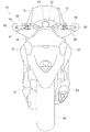
図3は本発明に係る車両の背面図であり、ウインドシールド31の後方で且つバーハンドル32の前方にメータ71及びEL(Electro−Luminescence)表示器72からなる表示装置73を配置し、バーハンドル32の左右に設けたグリップ74,76の前方を前述の側方突出部62,63で覆い、後部カバー部材18の左右にリヤコンビネーションランプ21,22を配置したことを示す。
FIG. 3 is a rear view of the vehicle according to the present invention. A
リヤコンビネーションランプ21,22は、それぞれが、テールランプ、ストップランプ及びリヤウインカの機能を有するものである。
図中の81はクラッチレバー、82はフロントブレーキレバー、83は排気装置の消音器である。
Each of the
In the figure, 81 is a clutch lever, 82 is a front brake lever, and 83 is a silencer of an exhaust device.
以上の述べた車両10の詳細構造を次に説明する。
図4は本発明に係る車両の外観図であり、車両10の一部を覆う車体カバー11は、カウル部材を兼ね、車体フレーム(不図示)に取付けられ、その前部から後部を覆う本体部カバー部材202と、運転者が昇降の際、足を通す足通し空間の下方に設ける足通し部カバー部材203と、本体部カバー部材202の後部上方に設けるとともに乗員シート41の下方を覆う後部カバー部材18とからなる。
Next, the detailed structure of the
FIG. 4 is an external view of a vehicle according to the present invention. A
後部カバー部材18の表面18aと、本体部カバー部材202の後部202cに備える表面202aとは側方から見て滑らかに連続するように形成したので、乗員シート41が閉じているときに、後部カバー部材18と本体部カバー部材202の後部202cとは、一体感をもたせることができ、車両全体としてシートカウル206とみることができる。
Since the
従って、後部カバー部材18は上部シートカウル207と見なすことができ、本体部カバー部材202の後部202cは下部シートカウル208と見なすことができる。
ここで、211はフロントフォーク33の摺動部を覆うチッピングガード、212はドライブシャフト47(図1参照)を覆うドライブシャフトカバー、213は前輪34の車軸、214,216は変速ペダルの前端部及び後端部に設けた踏部、217は後輪46の車軸、218はドライブシャフト47(図1参照)と後輪46とを連結する駆動ケースである。
Therefore, the
Here, 211 is a chipping guard that covers the sliding portion of the
図5は本発明に係る車両の後部側面図であり、乗員シート41は、運転者用シート221と同乗者用シート222とに分割して構成し、同乗者用シート222は、運転者用シート221とは独立して開閉可能に構成することを特徴とする。
また、車体後部に設ける左右のリヤコンビネーションランプ21,22(手前側の符号21のみ示す。)は、上部シートカウル207と下部シートカウル208との間に設けた開口部43,43(手前側の符号43のみ示す。)の後方に配置する。
FIG. 5 is a rear side view of the vehicle according to the present invention. The
In addition, left and right
一般に、リヤコンビネーションランプはリヤーカウルに凹部を設け、この凹部に収納する。そのため、リヤーカウルの形状が複雑化し、高価になる。
この点、本発明では、リヤコンビネーションランプ21,22は、開口部43に配置したので、シートカウル206に凹部を設ける必要が無く、設けたとしても浅い凹部ですませることができる。この結果、シートカウル206の形状が簡単になり、シートカウル206を含む車体カバー11の製造費用を低減することができる。
Generally, a rear combination lamp is provided with a recess in a rear cowl and is housed in this recess. Therefore, the shape of the rear cowl becomes complicated and expensive.
In this regard, in the present invention, since the
以上に述べた同乗者用シート222の作用を次に説明する。
図6は本発明に係る同乗者用シートの作用を示す作用図であり、同乗者用シート222は、運転者用シート221とは独立させるとともに、ヒンジ部224で開閉可能に構成した。
仮に、運転用シートに同乗者用シートを連続させた一体型タンデムシートで乗員シートを構成したとすると、この乗員シートは大型になり重くなる。
Next, the operation of the
FIG. 6 is an operation diagram showing the operation of the passenger seat according to the present invention. The
Assuming that the occupant seat is composed of an integrated tandem seat in which a passenger seat is made continuous with a driver seat, the occupant seat becomes large and heavy.
この点、本発明では運転者用シート221と同乗者用シート222とを分離した乗員シート41を採用した。
同乗者用シート222は必然的に小型になり軽くなるため、開閉は極めて容易になる。
In this regard, in the present invention, the
The
図7は本発明に係る車両の後部斜視図(ただし、同乗者用シート222を開いている。)であり、車両10の後部は、物品を収納するために車体後部に設けた収納部231と、この収納部231を開閉可能に覆う同乗者用シート222と、この同乗者用シート222の下方を覆うシートカウルの一部を構成する下部シートカウル208と、乗員が握るために車体フレームの後部に設けたグラブレール42,42とを備える。
なお、本実施例において、収納部231には2つのヘルメットが収納可能である。
FIG. 7 is a rear perspective view of the vehicle according to the present invention (however, the
In the present embodiment, two helmets can be stored in the
図8は本発明に係る車両を後方からみた外観図であり、同乗者用シート222を開閉させるための開閉スイッチ241を、シートカウル206の後端部206bに備える。
同乗者用シート222を開閉させる開閉スイッチ241を、シートカウル206の後端部206bに備えたので、車両10の両側から同乗者用シート222の開閉操作が可能となる。これにより、同乗者用シート222を開閉する場合の操作性を高めることができる。
FIG. 8 is an external view of the vehicle according to the present invention as viewed from the rear, and an open /
Since the opening /
図9は本発明に係るフロントウインカの正面図であり、フロントウインカ16は、複数のLED(不図示)と、複数のLEDを上部に取付けるとともに、LEDの光を反射させるリフレクタを形成したランプハウジング111と、このランプハウジング111の前部に取付けたカットを施したレンズ112とからなる。ランプハウジング111は、上部にLEDを取付ける複数のLED取付部121〜137を備える。なお、フロントウインカ17(図2参照)は、フロントウインカ16と左右対称で基本構造が同一であり、説明は省略する。
FIG. 9 is a front view of a front winker according to the present invention. The
図10は本発明に係るフロントウインカの平面図(図中の矢印(FRONT)は車両前方を表す。)であり、フロントウインカ16は、ランプハウジング111の車体中心側(図の右方)の幅を狭くし、車両側方(図の左方)にいくにつれて幅を次第に広くし、車両側方斜め後方に延びるように配置したものであり、ランプハウジング111の上部に設けたLED取付部121〜137は、ランプハウジング111の背面111aに沿うように並べて配置した部分である。ランプハウジング111に取付けたレンズ112の前面112aも車両側方斜め後方に延びる。
FIG. 10 is a plan view of the front winker according to the present invention (the arrow (FRONT in the figure represents the front of the vehicle)), and the
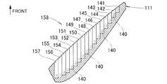
図11は本発明に係るフロントウインカの断面図であり、ほぼ水平面で切断し、図10と同一の方向から見たものである。
フロントウインカ16のランプハウジング111は、各LED取付部121〜137(図5参照)にそれぞれ取付けたLED140(想像線で示した部分である。)の光をほぼ車両前方へ反射させる帯状の湾曲面141〜157を車幅方向に階段状に形成したものである。これらの湾曲面141〜157はリフレクタ158を構成する部分である。
FIG. 11 is a cross-sectional view of the front blinker according to the present invention, which is cut along a substantially horizontal plane and viewed from the same direction as FIG.
The
図12は図10の12矢視図(但し、レンズ112は省いた。)であり、ランプハウジング111の上部に設けた上壁160にLED取付部121〜137(符号121,122,133〜137のみ示す。)に通じる貫通穴161〜177(符号161〜171のみ示す。)を開け、これらの貫通穴161〜177の下方に凹状に湾曲した湾曲面141〜157(141〜153のみ示す。)を配置したことを示す。
各貫通穴161〜177は、LED取付部121〜137に取付けたLED140(図14参照)が発した光を湾曲面141〜157に導く部分である。
12 is a view taken in the direction of the
Each through-hole 161-177 is a part which guide | induces the light which LED140 (refer FIG. 14) attached to LED attachment part 121-137 to the curved surfaces 141-157.
図13は本発明に係るランプハウジングの断面図(湾曲面148を通って鉛直に切断したもの)であり、ランプハウジング111の上壁160にLED取付部128を形成し、このLED取付部128にLED140を取付け、LED140を貫通穴168を介して湾曲面148に臨ませ、LED140をリフレクタの湾曲面148で光りが反射した方向から見えない領域に配置したことを示す。
他の湾曲面141〜147,149〜157(図6参照)を通る鉛直断面は、上記の湾曲面148を通る鉛直断面と同様であり、説明は省略する。
FIG. 13 is a cross-sectional view of the lamp housing according to the present invention (cut vertically through the curved surface 148). An
The vertical cross sections passing through the other
以上に述べたフロントウインカ16,17の作用を次に説明する。
図14(a),(b)は本発明に係るフロントウインカの作用を示す作用図である。
(a)において、LED140を点灯させると、LED140の光は、矢印で示すように、貫通穴168を通って湾曲面148に至り、湾曲面148で反射して車両前方へ進行する。また、LED140はレンズ112を通して見えない位置にあるため、外観性を向上させることができる。
Next, the operation of the
14 (a) and 14 (b) are operation diagrams showing the operation of the front winker according to the present invention.
In (a), when the
(b)において、各LED140を点灯させると、各LED140の光は、例えば、矢印Aで示すように、湾曲面143で反射して車両前方へ進み、レンズ112のカットにより屈折して車両側方へ進む。
In (b), when each
また、矢印Bで示すように、湾曲面149で反射して車両前方へ進み、レンズ112のカットにより屈折して車両前方へ進む。
更に、矢印Cで示すように、湾曲面155で反射して車両前方へ進み、レンズ112のカットにより屈折して車両側方斜め前方へ進む。
このようにして、全てのLED140から発せられ、レンズ112で屈折した光は、図に示す角度θ(例えば、約90°)の範囲で進行し、この角度θの方向から視認される。
Further, as indicated by an arrow B, the light is reflected by the
Furthermore, as indicated by an arrow C, the light is reflected by the
In this way, the light emitted from all the
以上の図9、図11及び図13に示したように、本発明は第1に、ランプハウジング111と、このランプハウジング111に設けたLED140と、このLED140の光を反射させる湾曲面141〜157と、ランプハウジング111の開口に取付けたレンズ112とからなる車両用方向指示灯としてのフロントウインカ16,17において、リフレクタ158に反射面となる凹状に湾曲した湾曲面141〜157を複数備え、これらの湾曲面141〜157で光が反射した方向から見えない領域にLED140を配置したことを特徴とする。
フロントウインカ16,17を外部から見たときに、LED140が見えないため、車両の外観性を向上させることができる。
As shown in FIGS. 9, 11, and 13, the present invention firstly includes the
When the front turn signals 16 and 17 are viewed from the outside, the
本発明は第2に、湾曲面141〜157を、平面視で車幅方向に階段状に複数配列し、1個のLED140に付き一つの湾曲面を備え、レンズ面、即ちレンズ112の前面112aを、車両側方斜め後方に延ばしたことを特徴とする。
車両前方及び車両側方からLED140の反射光を視認することができ、フロントウインカ16,17の視認性を向上させることができる。
Secondly, according to the present invention, a plurality of
The reflected light of the
本発明は第3に、LED140をランプハウジング111の上部に配置したことを特徴とする。
フロントウインカ16,17よりも高い位置からはランプハウジング111の上部のLED140が見えにくくなり、車両10の外観性を向上させることができる。
Third, the present invention is characterized in that the
The
尚、本発明では、1個のLEDに付き一つの湾曲面を備えるが、これに限らず、1個のLEDに付き複数の湾曲面を備えてもよいし、複数のLEDに付き一つの湾曲面を備えるようにしてもよい。 In the present invention, one curved surface is provided for one LED. However, the present invention is not limited to this, and a plurality of curved surfaces may be provided for one LED, or one curved surface may be provided for a plurality of LEDs. A surface may be provided.
本発明の方向指示灯は、自動二輪車に好適である。 The direction indicator lamp of the present invention is suitable for a motorcycle.
10…車両、16,17…方向指示灯(フロントウインカ)、111…ランプハウジング、112…レンズ、112a…レンズの前面、121〜137…LED取付部、140…LED、141〜157…湾曲面、158…リフレクタ、160…上壁、161〜177…貫通穴。
DESCRIPTION OF
Claims (1)
前記リフレクタ(158)は反射面となる凹状に湾曲した湾曲面(141〜157)を備え、
前記ランプハウジング(111)に平面視で車幅方向に複数配列された階段状の前記湾曲面(141〜157)を形成し、これらの湾曲面(141〜157)でリフレクタ(158)を形成し、
前記ランプハウジング(111)の上壁(160)に上方に突出する筒状のLED取付部(121〜137)を一体に設け、
上壁の上方に突出した筒状の前記LED取付部(121〜137)に内部を貫通する貫通穴(161〜177)を設け、この貫通穴(161〜177)に、上から内部を臨むように前記LED取付部(121〜137)に前記LED(140)を取付け、
前記LEDを取付けた貫通穴(161〜177)の下方に前記凹状の湾曲面を配置し、
前記湾曲面(141〜157)で光が反射した方向から見えない領域に前記LED(140)を配置し、
前記レンズ(112)の前面(112a)は、車両側方斜め後方に延び、
前記LED(140)は、1個のLED(140)に付き一つの前記湾曲面(141〜157)に備える、
ことを特徴とする車両用方向指示灯。 A lamp housing (111), an LED (140) provided in the lamp housing (111), a reflector (158) for reflecting the light of the LED (140), and a lens attached to the opening of the lamp housing (111) In the vehicle direction indicator lamp (16, 17) consisting of (112),
The reflector (158) includes a curved surface (141 to 157) curved in a concave shape as a reflective surface,
A plurality of stepped curved surfaces (141 to 157) arranged in the vehicle width direction in a plan view are formed on the lamp housing (111), and a reflector (158) is formed by these curved surfaces (141 to 157). ,
The lamp housing (111) of the top wall (160) in a cylindrical L ED mounting portion protruding upwardly (121-137) formed integrally,
Through-holes (161 to 177) penetrating the inside are provided in the cylindrical LED mounting portions (121 to 137) protruding above the upper wall, and the inside of the through-holes (161 to 177) faces the inside from above. The LED (140) is attached to the LED attachment portion (121 to 137).
The concave curved surface is disposed below the through holes (161 to 177) to which the LEDs are attached,
The LED (140) is disposed in a region that cannot be seen from the direction in which light is reflected by the curved surfaces (141 to 157),
The front surface (112a) of the lens (112) extends obliquely rearward to the vehicle side,
The LED (140) is provided on one curved surface (141 to 157) per one LED (140).
A vehicle direction indicator lamp.
Priority Applications (4)
| Application Number | Priority Date | Filing Date | Title |
|---|---|---|---|
| JP2005293055A JP4594205B2 (en) | 2005-10-05 | 2005-10-05 | Direction indicator lights for vehicles |
| TW095135970A TW200726670A (en) | 2005-10-05 | 2006-09-28 | Direction indicator lamp for vehicle |
| US11/529,670 US7401959B2 (en) | 2005-10-05 | 2006-09-28 | Turn signal lamp for a vehicle |
| CN2006101418208A CN1945106B (en) | 2005-10-05 | 2006-09-30 | Turn signal lamp for a vehicle |
Applications Claiming Priority (1)
| Application Number | Priority Date | Filing Date | Title |
|---|---|---|---|
| JP2005293055A JP4594205B2 (en) | 2005-10-05 | 2005-10-05 | Direction indicator lights for vehicles |
Publications (2)
| Publication Number | Publication Date |
|---|---|
| JP2007103210A JP2007103210A (en) | 2007-04-19 |
| JP4594205B2 true JP4594205B2 (en) | 2010-12-08 |
Family
ID=37901700
Family Applications (1)
| Application Number | Title | Priority Date | Filing Date |
|---|---|---|---|
| JP2005293055A Expired - Fee Related JP4594205B2 (en) | 2005-10-05 | 2005-10-05 | Direction indicator lights for vehicles |
Country Status (4)
| Country | Link |
|---|---|
| US (1) | US7401959B2 (en) |
| JP (1) | JP4594205B2 (en) |
| CN (1) | CN1945106B (en) |
| TW (1) | TW200726670A (en) |
Families Citing this family (19)
| Publication number | Priority date | Publication date | Assignee | Title |
|---|---|---|---|---|
| JP4532380B2 (en) * | 2005-09-29 | 2010-08-25 | 本田技研工業株式会社 | Motorcycle |
| US7497606B1 (en) * | 2007-09-17 | 2009-03-03 | Lucidity Enterprise Co., Ltd. | Reflective rear light for a truck |
| JP5150336B2 (en) * | 2008-03-28 | 2013-02-20 | スタンレー電気株式会社 | LED lamp |
| DE102011119230B4 (en) * | 2011-11-23 | 2013-07-11 | Audi Ag | Car flashing light and method for operating a flashing light |
| JP5782424B2 (en) * | 2012-12-13 | 2015-09-24 | 本田技研工業株式会社 | Rear structure of saddle-ride type vehicle |
| US8928226B1 (en) | 2013-08-01 | 2015-01-06 | Myotek Pacific Corp. | Combination LED fog lamp and daytime running lamp |
| KR101673655B1 (en) | 2014-01-29 | 2016-11-07 | 엘지이노텍 주식회사 | Lamp unit for vehicle |
| US11211305B2 (en) | 2016-04-01 | 2021-12-28 | Texas Instruments Incorporated | Apparatus and method to support thermal management of semiconductor-based components |
| US10861796B2 (en) | 2016-05-10 | 2020-12-08 | Texas Instruments Incorporated | Floating die package |
| USD796094S1 (en) | 2016-07-19 | 2017-08-29 | Myotek Pacific Corp. | LED fog lamp |
| US10179730B2 (en) | 2016-12-08 | 2019-01-15 | Texas Instruments Incorporated | Electronic sensors with sensor die in package structure cavity |
| US9761543B1 (en) | 2016-12-20 | 2017-09-12 | Texas Instruments Incorporated | Integrated circuits with thermal isolation and temperature regulation |
| US9865537B1 (en) | 2016-12-30 | 2018-01-09 | Texas Instruments Incorporated | Methods and apparatus for integrated circuit failsafe fuse package with arc arrest |
| US10411150B2 (en) | 2016-12-30 | 2019-09-10 | Texas Instruments Incorporated | Optical isolation systems and circuits and photon detectors with extended lateral P-N junctions |
| US10074639B2 (en) | 2016-12-30 | 2018-09-11 | Texas Instruments Incorporated | Isolator integrated circuits with package structure cavity and fabrication methods |
| US9929110B1 (en) * | 2016-12-30 | 2018-03-27 | Texas Instruments Incorporated | Integrated circuit wave device and method |
| US10121847B2 (en) | 2017-03-17 | 2018-11-06 | Texas Instruments Incorporated | Galvanic isolation device |
| USD874715S1 (en) | 2018-03-07 | 2020-02-04 | Myotek Holdings, Inc. | LED spot lamp lens |
| US20220404054A1 (en) * | 2019-12-10 | 2022-12-22 | 3M Innovative Properties Company | Powered room air purifier with air-quality visual indicator |
Citations (8)
| Publication number | Priority date | Publication date | Assignee | Title |
|---|---|---|---|---|
| JPH0589703A (en) * | 1991-09-30 | 1993-04-09 | Koito Mfg Co Ltd | Vehicle lighting fixture |
| JP2002100217A (en) * | 2000-09-22 | 2002-04-05 | Stanley Electric Co Ltd | Vehicular led lamp fitting |
| JP2002157904A (en) * | 2000-11-17 | 2002-05-31 | Stanley Electric Co Ltd | Led light source device |
| JP2003059313A (en) * | 2001-08-15 | 2003-02-28 | Koito Mfg Co Ltd | Vehicule lighting device |
| JP2004047221A (en) * | 2002-07-10 | 2004-02-12 | Koito Mfg Co Ltd | Vehicular lighting fixture |
| JP2004227981A (en) * | 2003-01-24 | 2004-08-12 | Stanley Electric Co Ltd | Vehicular lamp |
| JP2004265697A (en) * | 2003-02-28 | 2004-09-24 | Toyota Industries Corp | Signal lamp and reflecting structure of signal lamp fitting |
| JP2005122944A (en) * | 2003-10-14 | 2005-05-12 | Honda Motor Co Ltd | Vehicular lighting device |
Family Cites Families (16)
| Publication number | Priority date | Publication date | Assignee | Title |
|---|---|---|---|---|
| US4929866A (en) * | 1987-11-17 | 1990-05-29 | Mitsubishi Cable Industries, Ltd. | Light emitting diode lamp |
| JPH01146202A (en) * | 1987-12-01 | 1989-06-08 | Koito Mfg Co Ltd | Vehicle lighting appliance |
| US5241457A (en) * | 1991-01-18 | 1993-08-31 | Nippon Sheet Glass Co., Ltd. | Rear window stop lamp for motor vehicles |
| FR2680859B1 (en) * | 1991-09-02 | 1993-10-29 | Valeo Vision | OPTICAL COLLIMATION ELEMENT AND ITS ASSOCIATED SUPPORT ELEMENT, IN PARTICULAR FOR A MOTOR VEHICLE SIGNALING LIGHT. |
| US5471371A (en) * | 1993-01-08 | 1995-11-28 | Ford Motor Company | High efficiency illuminator |
| ES2190599T3 (en) * | 1997-08-07 | 2003-08-01 | Decoma Int Inc | LIGHT MANAGEMENT SYSTEM DELGADO AND DISTRIBUTE TO GUIDE THE LIGHT OF ONE OR MORE LIGHT SOURCES AND STRUCTURES MANUFACTURING METHOD FOR USE IN OPTICAL SYSTEM. |
| JP2000123610A (en) | 1998-10-09 | 2000-04-28 | Ichikoh Ind Ltd | Lamp for vehicle having led as light source |
| US6280480B1 (en) * | 1998-10-30 | 2001-08-28 | Meridian Automotive Systems, Inc. | Indirect illumination taillamp assembly for a vehicle |
| DE20001407U1 (en) * | 2000-01-27 | 2000-03-16 | Reitter & Schefenacker Gmbh | Exterior rear view mirror for vehicles, preferably for motor vehicles |
| US6612728B2 (en) * | 2000-07-07 | 2003-09-02 | Truck-Lite Co., Inc. | Marker lamp with picture frame optics |
| JP2003100114A (en) * | 2001-09-19 | 2003-04-04 | Koito Mfg Co Ltd | Vehicular lamp |
| JP3953764B2 (en) * | 2001-09-20 | 2007-08-08 | 株式会社小糸製作所 | Vehicle lighting |
| JP3998999B2 (en) * | 2002-03-06 | 2007-10-31 | 株式会社小糸製作所 | Vehicle lighting |
| JP4027688B2 (en) * | 2002-03-15 | 2007-12-26 | 株式会社小糸製作所 | Vehicle lighting |
| US7059754B2 (en) * | 2002-06-27 | 2006-06-13 | North American Lighting, Inc. | Apparatus and method for providing a modular vehicle light device |
| US7070311B2 (en) * | 2004-06-03 | 2006-07-04 | Fu An Industrial Co., Ltd. | Vehicle light for producing light whose form depends on orientations of plural refraction elements |
-
2005
- 2005-10-05 JP JP2005293055A patent/JP4594205B2/en not_active Expired - Fee Related
-
2006
- 2006-09-28 US US11/529,670 patent/US7401959B2/en not_active Expired - Fee Related
- 2006-09-28 TW TW095135970A patent/TW200726670A/en not_active IP Right Cessation
- 2006-09-30 CN CN2006101418208A patent/CN1945106B/en not_active Expired - Fee Related
Patent Citations (8)
| Publication number | Priority date | Publication date | Assignee | Title |
|---|---|---|---|---|
| JPH0589703A (en) * | 1991-09-30 | 1993-04-09 | Koito Mfg Co Ltd | Vehicle lighting fixture |
| JP2002100217A (en) * | 2000-09-22 | 2002-04-05 | Stanley Electric Co Ltd | Vehicular led lamp fitting |
| JP2002157904A (en) * | 2000-11-17 | 2002-05-31 | Stanley Electric Co Ltd | Led light source device |
| JP2003059313A (en) * | 2001-08-15 | 2003-02-28 | Koito Mfg Co Ltd | Vehicule lighting device |
| JP2004047221A (en) * | 2002-07-10 | 2004-02-12 | Koito Mfg Co Ltd | Vehicular lighting fixture |
| JP2004227981A (en) * | 2003-01-24 | 2004-08-12 | Stanley Electric Co Ltd | Vehicular lamp |
| JP2004265697A (en) * | 2003-02-28 | 2004-09-24 | Toyota Industries Corp | Signal lamp and reflecting structure of signal lamp fitting |
| JP2005122944A (en) * | 2003-10-14 | 2005-05-12 | Honda Motor Co Ltd | Vehicular lighting device |
Also Published As
| Publication number | Publication date |
|---|---|
| US7401959B2 (en) | 2008-07-22 |
| US20070076421A1 (en) | 2007-04-05 |
| JP2007103210A (en) | 2007-04-19 |
| TW200726670A (en) | 2007-07-16 |
| CN1945106B (en) | 2010-12-01 |
| CN1945106A (en) | 2007-04-11 |
| TWI303228B (en) | 2008-11-21 |
Similar Documents
| Publication | Publication Date | Title |
|---|---|---|
| JP4594205B2 (en) | Direction indicator lights for vehicles | |
| US7588356B2 (en) | Structure of tail light for motorcycle | |
| JP4563912B2 (en) | Vehicle headlamp structure | |
| JP5534677B2 (en) | Motorcycle position lights and lighting equipment | |
| JP5660726B2 (en) | Vehicle lighting system | |
| JP4630780B2 (en) | Arrangement structure of scooter type vehicles | |
| JP4499646B2 (en) | Vehicle rear combination lamp | |
| JP5732504B2 (en) | Vehicle taillight structure | |
| JP5011094B2 (en) | Vehicle lighting structure | |
| JP2009181913A (en) | Headlight device of vehicle | |
| CN100572895C (en) | Vehicle light implement structure | |
| JP5624200B2 (en) | Vehicle headlamp device | |
| JP4815628B2 (en) | Headlight structure | |
| US9988120B2 (en) | Direction indicator and rearview mirror structure of vehicle | |
| JP6827525B2 (en) | Lighting device for saddle-mounted vehicles | |
| CN110316289B (en) | Saddle-riding type vehicle | |
| TWI438113B (en) | Straddle type vehicle | |
| JP5564011B2 (en) | Rear structure of the vehicle | |
| JP2003170876A (en) | Rear structure of vehicle | |
| JP3889610B2 (en) | Body front structure | |
| JP5578035B2 (en) | Motorcycle headlamp device | |
| TWI708700B (en) | Straddle vehicle | |
| JP7050846B2 (en) | Rear fender structure of saddle-riding vehicle | |
| JP4425764B2 (en) | Motorcycle headlamp structure | |
| JP6894416B2 (en) | Saddle-type vehicle |
Legal Events
| Date | Code | Title | Description |
|---|---|---|---|
| A621 | Written request for application examination |
Free format text: JAPANESE INTERMEDIATE CODE: A621 Effective date: 20071127 |
|
| A977 | Report on retrieval |
Free format text: JAPANESE INTERMEDIATE CODE: A971007 Effective date: 20090812 |
|
| A131 | Notification of reasons for refusal |
Free format text: JAPANESE INTERMEDIATE CODE: A131 Effective date: 20090819 |
|
| A521 | Request for written amendment filed |
Free format text: JAPANESE INTERMEDIATE CODE: A523 Effective date: 20091016 |
|
| A131 | Notification of reasons for refusal |
Free format text: JAPANESE INTERMEDIATE CODE: A131 Effective date: 20100420 |
|
| A521 | Request for written amendment filed |
Free format text: JAPANESE INTERMEDIATE CODE: A523 Effective date: 20100611 |
|
| TRDD | Decision of grant or rejection written | ||
| A01 | Written decision to grant a patent or to grant a registration (utility model) |
Free format text: JAPANESE INTERMEDIATE CODE: A01 Effective date: 20100914 |
|
| A01 | Written decision to grant a patent or to grant a registration (utility model) |
Free format text: JAPANESE INTERMEDIATE CODE: A01 |
|
| A61 | First payment of annual fees (during grant procedure) |
Free format text: JAPANESE INTERMEDIATE CODE: A61 Effective date: 20100916 |
|
| FPAY | Renewal fee payment (event date is renewal date of database) |
Free format text: PAYMENT UNTIL: 20130924 Year of fee payment: 3 |
|
| R150 | Certificate of patent or registration of utility model |
Free format text: JAPANESE INTERMEDIATE CODE: R150 |
|
| FPAY | Renewal fee payment (event date is renewal date of database) |
Free format text: PAYMENT UNTIL: 20140924 Year of fee payment: 4 |
|
| LAPS | Cancellation because of no payment of annual fees |