JP5011094B2 - Vehicle lighting structure - Google Patents
Vehicle lighting structure Download PDFInfo
- Publication number
- JP5011094B2 JP5011094B2 JP2007338092A JP2007338092A JP5011094B2 JP 5011094 B2 JP5011094 B2 JP 5011094B2 JP 2007338092 A JP2007338092 A JP 2007338092A JP 2007338092 A JP2007338092 A JP 2007338092A JP 5011094 B2 JP5011094 B2 JP 5011094B2
- Authority
- JP
- Japan
- Prior art keywords
- reflector
- sub
- lens
- bulb
- light
- Prior art date
- Legal status (The legal status is an assumption and is not a legal conclusion. Google has not performed a legal analysis and makes no representation as to the accuracy of the status listed.)
- Expired - Fee Related
Links
Images


Landscapes
- Lighting Device Outwards From Vehicle And Optical Signal (AREA)
- Non-Portable Lighting Devices Or Systems Thereof (AREA)
Description
この発明は、自動二輪車等に好適な車両用灯火器構造に関する。 The present invention relates to a vehicular lamp structure suitable for a motorcycle or the like.
従来、自動二輪車の車両用灯火器構造において、バルブ光をメインリフレクタの反射方向とは異なる方向にも配光可能としたものがある(例えば、特許文献1参照。)。
ところで、上記従来の技術は、メインリフレクタ周囲の隙間やメインリフレクタに設けた開口からバルブ光を漏らして配光するのみであることから、バルブ光が拡散し易く、十分な明るさを確保することが課題であった。
そこでこの発明は、バルブ光をメインリフレクタの反射方向とは異なる方向にも配光可能とした車両用灯火器構造において、前記異なる方向へのバルブ光の十分な明るさの確保及び的確な配光を可能とすることを目的とする。
By the way, the above-mentioned conventional technique only distributes light by leaking valve light from a gap around the main reflector or an opening provided in the main reflector, so that the valve light is easily diffused and sufficient brightness is ensured. Was an issue.
Accordingly, the present invention provides a vehicle lighting device structure in which bulb light can be distributed in a direction different from the reflection direction of the main reflector, ensuring sufficient brightness of the bulb light in the different directions and accurate light distribution. It aims to make it possible.
上記課題の解決手段として、請求項1に記載した発明は、ハウジング(64)及びレンズ(65)からなる灯体(63)内にバルブ(66)及びメインリフレクタ(67)を備え、前記バルブ(66)からのバルブ光を前記メインリフレクタ(67)の反射方向とは異なる方向にも配光可能とした車両用灯火器(62)の構造において、前記メインリフレクタ(67)は、前記レンズ(65)側に向けて壁状に立ち上げ、その突出端を前記レンズ(65)の内面に近接させることで、前記ハウジング(64)内を前記バルブ(66)が配置される主灯室(71)と、前記メインリフレクタ(67)の背後側に配置される副灯室(72)とに仕切るものであって、前記メインリフレクタ(67)には、該メインリフレクタ(67)の背後側に配置される前記副灯室(72)に前記バルブ光を導くものであって、その幅が前記副灯室(72)の幅よりも狭く設定されるスリット(81)が設けられ、前記副灯室(72)には、前記スリット(81)が導いたバルブ光の照射方向に沿って前記副灯室(72)に延在するサブリフレクタ(82)を備え、前記スリット(81)の幅(h1)と前記サブリフレクタ(82)の幅(h2)とが略同一とされ、前記スリット(81)を通じて前記メインリフレクタ(67)の背後に導いたバルブ光が、前記サブリフレクタ(82)によって前記メインリフレクタ(67)の反射方向とは異なる方向に配光されると共に、前記灯火器(62)は、車両(1)のフロントカバー(51)に左右一対に設けられ、前記サブリフレクタ(82)は、前記メインリフレクタ(67)の後方かつ前記フロントカバー(51)の左右縁(51c)近傍で、該左右縁(51c)に沿うように斜め上後方に向けて延設され、前記灯火器(62)は、前記フロントカバー(51)の左右内側に位置するヘッドランプ(61)の上方に連続するように設けられることを特徴とする。
As a means for solving the above problems, the invention described in
請求項2に記載した発明は、前記サブリフレクタ(82)が前記メインリフレクタ(67)と一体に形成されるものであって、前記スリット(81)は、前記レンズ(65)側に開放するU字状に形成されることを特徴とする。 According to a second aspect of the present invention, the sub-reflector (82) is formed integrally with the main reflector (67), and the slit (81) is opened to the lens (65) side. It is formed in a letter shape.
請求項3に記載した発明は、前記サブリフレクタ(82)に階段状の反射面(82a,82b)が形成され、該階段状の反射面(82a,82b)は、前記バルブ(66)側を向き、前記バルブ(66)からの光を直接受け、前記副灯室(72)に対向する副レンズ(65b)に概ね直交するようにバルブ光を反射する第一反射面(82a)と、前記バルブ(66)の反対側を向き、前記バルブ(66)からのバルブ光が前記副レンズ(65b)の内面にて反射された後に受け、この反射されたバルブ光を前記バルブ(66)の反対方向に反射する第二反射面(82b)とからなることを特徴とする。 According to a third aspect of the present invention, a step-like reflecting surface (82a, 82b) is formed on the sub-reflector (82), and the step-like reflecting surface (82a, 82b) faces the bulb (66) side. A first reflecting surface (82a) for directly receiving the light from the bulb (66) and reflecting the bulb light so as to be substantially orthogonal to the secondary lens (65b) facing the secondary lamp chamber (72); The bulb (66) faces away from the bulb (66), and the bulb light from the bulb (66) is reflected on the inner surface of the sub-lens (65b). The reflected bulb light is opposite to the bulb (66). It consists of the 2nd reflective surface (82b) reflected in a direction, It is characterized by the above-mentioned.
請求項4に記載した発明は、前記レンズ(65)における少なくとも前記サブリフレクタ(82)と対向する部位の内面に、前記バルブ光の一部を前記サブリフレクタ(82)に向けて反射させるレンズカットが施されることを特徴とする。 According to a fourth aspect of the present invention, a lens cut that reflects a part of the bulb light toward the sub-reflector (82) on at least an inner surface of a portion of the lens (65) facing the sub-reflector (82). Is provided.
請求項5に記載した発明は、前記フロントカバー(51)は、その前部において前下がりの傾斜面を形成する傾斜前壁部(51a)と、該傾斜前壁部(51a)の下部両側から斜め下後方に延びる左右側壁部(51b)とを一体に有し、前記傾斜前壁部(51a)に、前記ヘッドランプ(61)及び左右のフロントウインカ(62)が設けられることを特徴とする。 According to a fifth aspect of the present invention, the front cover (51) includes an inclined front wall portion (51a) that forms an inclined surface that is inclined downward at the front portion thereof, and both sides of the lower portion of the inclined front wall portion (51a). The headlamp (61) and the left and right front turn signals (62) are provided on the inclined front wall (51a) integrally with left and right side walls (51b) extending obliquely downward and rearward. .
請求項6に記載した発明は、前記ヘッドランプ(61)は、前記傾斜前壁部(51a)の下部の左右方向内側に位置し、かつ上側に向けて先細りに延びる縦長の左右レンズ面(61a)を前面視V字状にして配置されることを特徴とする。
請求項7に記載した発明は、前記灯火器(62)は、前記ヘッドランプ(61)のレンズ面(61a)の上端部から前記傾斜前壁部(51a)の上端部左右外側の角部に至るまで後上がりに延びることを特徴とする。
請求項8に記載した発明は、前記灯火器(62)のヘッドランプ(61)側の端部(68)は、ヘッドランプ(61)側に側面視三角形状をなして突出することを特徴とする。
請求項9に記載した発明は、前記灯火器(62)の傾斜前壁部(51a)の上端側における端部(69)は、傾斜前壁部(51a)の上端部左右外側の角部近傍において後上がりに延びると共に、その末端が前記傾斜前壁部(51a)の上部側縁を形成するべく後上がりの直線状に形成されることを特徴とする。
According to a sixth aspect of the present invention, the headlamp (61) has a vertically long left and right lens surface (61a) that is positioned on the inner side in the left-right direction at the lower portion of the inclined front wall portion (51a) and that tapers upward. ) Is arranged in a V shape when viewed from the front.
According to a seventh aspect of the present invention, the lighting device (62) is arranged from the upper end portion of the lens surface (61a) of the headlamp (61) to corners on the left and right outer sides of the upper end portion of the inclined front wall portion (51a). It is characterized by extending backwards.
The invention described in claim 8 is characterized in that an end portion (68) on the headlamp (61) side of the lighting device (62) protrudes in a triangular shape in a side view on the headlamp (61) side. To do.
According to the ninth aspect of the present invention, the end portion (69) on the upper end side of the inclined front wall portion (51a) of the lighting device (62) is near the corners on the left and right outer sides of the upper end portion of the inclined front wall portion (51a). , And the end thereof is formed in a straight line that rises rearward so as to form the upper side edge of the inclined front wall portion (51a).
この発明によれば、バルブ光をメインリフレクタの反射方向とは異なる方向にも配光するにあたり、メインリフレクタの背後に導いたバルブ光がサブリフレクタにより所望の照射方向に配光されることとなるため、単にバルブ光を前記異なる方向に漏らす場合と比べて、バルブ光の拡散が抑えられ、前記異なる方向へのバルブ光の十分な明るさの確保及び的確な配光が可能となり、灯火器の付加機能を高めて商品性向上を図ることができる。
また、スリットが導いたバルブ光の照射方向に沿ってサブリフレクタを延在させることで、前記レンズに細長の発光部分を設けることが可能となり、車両にシャープで斬新な印象を与えて外観性を高めることができる。
また、サブリフレクタによる発光部分が車両のフロントカバーの左右縁近傍に配置され、かつ該発光部分が斜め上後方に延びることでその照射範囲の上下幅も広がり、灯火器の被視認性を向上させることができる。また、左右の灯火器の間隔を広げて車両の幅方向における大きさをより大きく見せて視認性を向上させることができる。
また、車両のフロントカバーの左右内側から左右外側かつ左右縁近傍までヘッドランプ及び当該灯火器による発光部部分を延在させることができ、第三者が当該車両の速度感や距離感といった情報を把握し易くなると共に、ヘッドランプの上方に当該灯火器を一体的に連続させて外観性を向上させることができる。
さらに、スリットの幅とサブリフレクタの幅とが略同一とされることを細長でシャープな発光部分を効率よく形成することができる。
According to the present invention, when the bulb light is distributed in a direction different from the reflection direction of the main reflector, the bulb light guided behind the main reflector is distributed in a desired irradiation direction by the sub-reflector. Therefore, compared with the case where the bulb light is simply leaked in the different directions, the diffusion of the bulb light can be suppressed, and sufficient brightness of the bulb light in the different directions can be ensured and accurate light distribution can be achieved. Additional functions can be enhanced to improve merchantability.
In addition, by extending the sub-reflector along the direction of the bulb light guided by the slit, it becomes possible to provide an elongated light emitting portion on the lens, giving the vehicle a sharp and novel impression and improving the appearance. Can be increased.
In addition, the light emitting part by the sub-reflector is arranged in the vicinity of the left and right edges of the front cover of the vehicle, and the light emitting part extends obliquely upward and rearward so that the vertical width of the irradiation range is widened and the visibility of the lamp is improved. be able to. Further, the distance between the left and right lamps can be widened to make the size in the width direction of the vehicle appear larger, thereby improving the visibility.
In addition, the headlamp and the light emitting part of the lighting device can be extended from the left and right inner sides of the front cover of the vehicle to the left and right edges and near the left and right edges. It becomes easy to grasp, and the appearance can be improved by continuously connecting the lighting device above the headlamp.
Furthermore, it is possible to efficiently form an elongated and sharp light-emitting portion that the width of the slit and the width of the sub reflector are substantially the same.
また、サブリフレクタ(82)が前記メインリフレクタ(67)と一体に形成されることで、部品点数の削減による組み立て性の向上、コストダウン及び軽量化を図ることができる。Further, since the sub reflector (82) is formed integrally with the main reflector (67), the assemblability can be improved, the cost can be reduced, and the weight can be reduced by reducing the number of parts.
また、前記サブリフレクタ(82)に階段状の反射面(82a,82b)が形成されることで、スリットが導いたバルブ光をサブリフレクタの延在方向に渡って効率よく均等に配光することができる。Further, the step-shaped reflecting surfaces (82a, 82b) are formed on the sub-reflector (82), so that the valve light guided by the slit can be efficiently and evenly distributed over the extending direction of the sub-reflector. Can do.
また、前記レンズ(65)における少なくとも前記サブリフレクタ(82)と対向する部位の内面に、前記バルブ光の一部を前記サブリフレクタ(82)に向けて反射させるレンズカットが施されることで、スリットから直接レンズに至るようなバルブ光はサブリフレクタに向けて反射させることが可能となり、スリットが導いたバルブ光を無駄なく確実に配光することができる。Further, a lens cut for reflecting a part of the bulb light toward the sub-reflector (82) is applied to at least an inner surface of a portion of the lens (65) facing the sub-reflector (82). The bulb light that directly reaches the lens from the slit can be reflected toward the sub-reflector, and the bulb light guided by the slit can be reliably distributed without waste.
以下、この発明の実施例について図面を参照して説明する。なお、以下の説明における前後左右等の向きは、特に記載が無ければ車両における向きと同一とする。また、図中矢印FRは車両前方を、矢印LHは車両左方を、矢印UPは車両上方をそれぞれ示す。 Embodiments of the present invention will be described below with reference to the drawings. Note that the directions such as front, rear, left and right in the following description are the same as those in the vehicle unless otherwise specified. In the figure, the arrow FR indicates the front of the vehicle, the arrow LH indicates the left side of the vehicle, and the arrow UP indicates the upper side of the vehicle.
図1,2に示すスクータ型の自動二輪車(鞍乗り型車両)1において、車体フレーム2の前端部に位置するヘッドパイプ3には、前輪4を軸支する左右フロントフォーク5がステアリングステム5aを介して操舵可能に枢支される。ステアリングステム5aの上部には、操舵用のバーハンドル6が取り付けられる。なお、図2中線CSは車体左右中心面を示す。
In the scooter type motorcycle (saddle-ride type vehicle) 1 shown in FIGS. 1 and 2, left and
車体フレーム2は、ヘッドパイプ3から斜め下後方に一本のメインフレーム7を延ばし、ヘッドパイプ3と乗員用のシート13との間を低部として跨り易さを向上させたアンダーボーン型とされる。前記低部には、シート13に着座した乗員(運転者)の足を載せるフロアステップ54が配設される。
The
メインフレーム7の後端部は、車体下部の前後中間部において左右に延在するクロスフレーム8の左右中間部に接合される。クロスフレーム8の左右端部には、スイングユニット30の前部を懸架リンク41を介して上下揺動可能に支持する左右ピボットプレート9が接合される。
The rear end portion of the
また、クロスフレーム8の左右端部には、左右リヤフレーム11の前端部がそれぞれ接合される。左右リヤフレーム11は、クロスフレーム8から斜め上後方に延びる。左右リヤフレーム11の上方には、運転者用及び後部同乗者(パッセンジャー)用の座面を前後に有する前記シート13が配設される。
The front end portions of the left and right
スイングユニット30は、その前部のエンジン31と後部左側の動力伝達機構35とを一体化してなり、その前部が懸架リンク41を介して左右ピボットプレート9に上下揺動可能に支持され、かつ後部左側がリヤクッション42を介して左リヤフレーム11に近接離反可能に支持される。動力伝達機構35の後端部には後輪38が軸支される。
The
車体フレーム2は、主に合成樹脂からなるボディカバー50により覆われる。
ボディカバー50は、車体フレーム2の前部(ヘッドパイプ3及びメインフレーム7の上部周り)をその前方から覆うフロントカバー51と、車体フレーム2の前部を後方から覆うインナーカバー52と、フロントカバー51の下方に連続するように車体フレーム2の下部(メインフレーム7の下部周り)を下方から覆うアンダーカバー53と、車体フレーム2の下部を上方から覆う前記フロアステップ54と、車体フレーム2の後部前側(左右リヤフレーム11の前部周り)を前方から覆うリヤセンタカバー55と、車体フレーム2の後部(左右リヤフレーム11周り)を側方から覆う左右リヤサイドカバー56とを主になる。
The
The body cover 50 includes a
フロントカバー51は前輪4の上方に離間し、該フロントカバー51と前輪4との間には前輪4の上方を覆うフロントフェンダ58が設けられる。また、バーハンドル6周りはハンドルカバー57により覆われる。
フロントカバー51をはじめとするボディカバー50は車体フレーム2に固定的に取り付けられ、ハンドルカバー57及びフロントフェンダ58は前輪4及びバーハンドル6等と共にヘッドパイプ3周りに回動可能とされる。
The
The body cover 50 including the
フロントカバー51は、その前部において前下がりの傾斜面を形成する傾斜前壁部51aと、該傾斜前壁部51aの下部両側から斜め下後方に延びる左右側壁部51bとを一体に有する。
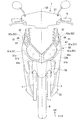
そして、フロントカバー51の傾斜前壁部51aには、左右ヘッドランプ61及び左右フロントウインカ62がそれぞれ配設される。
The
The left and
左右ヘッドランプ61は傾斜前壁部51aの下部の左右方向内側(左右内側)に位置し、上側に向けてやや先細りに延びる縦長の左右レンズ面61aを前面視V字状に配置してなる。なお、図中符号61bはヘッドランプ61の光源であるバルブを、符号61cはバルブ61bからの光を車両前方に向けて反射させるリフレクタをそれぞれ示す。
一方、左右フロントウインカ62は傾斜前壁部51aの上部の左右方向外側(左右外側)に位置し、上側に向けてやや先細りに延びる細長のレンズ面62aを左右ヘッドランプ61の左右レンズ面61aの上方にこれらと連続するように配置してなる。
The left and
On the other hand, the left and right front blinkers 62 are positioned on the outside in the left and right direction (left and right outside) of the upper part of the inclined
傾斜前壁部51aは、左右外側ほど後方に回り込むように全体的に湾曲し、該傾斜前壁部51aの湾曲形状に沿うように、左右ヘッドランプ61及び左右フロントウインカ62の各レンズ面61a,62bも左右外側ほど後方に回りこむように湾曲する。
以下、図3〜5に示す左フロントウインカ62を参照して説明を行うが、右フロントウインカ62は左右勝手違い対称の構成を有するものとする。
The inclined
Hereinafter, the description will be made with reference to the left
フロントウインカ62は、ハウジング64及びレンズ65からなる灯体63内に、光源であるバルブ66、及び該バルブ66からの光(バルブ光)を概ね車両前方に向けて反射させるメインリフレクタ67を備えてなる。
灯体63は、ヘッドランプ61のレンズ面61aの上端部から傾斜前壁部51aの上端部左右外側の角部に至るまで後上がりに延び、その外面が前記レンズ面62aを構成する。灯体63(レンズ面62a)のヘッドランプ61側の端部(基端部68)は、ヘッドランプ61側に側面視三角形状をなして突出する。なお、灯体63(レンズ面62a)の基端部68の上下辺をそれぞれ符号68a,68bで示す(図3参照)。
The
The
一方、灯体63(レンズ面62a)の傾斜前壁部51a上端側の端部(先端部69)は、傾斜前壁部51aの上端部左右外側の角部近傍において後下がりに僅かに延び、その末端(後端)が傾斜前壁部51aの上部側縁(後縁)を形成するべく比較的急傾斜をなす後上がりの直線状にカットされる。なお、灯体63(レンズ面62a)の先端部69の上下辺及び末端(後辺)をそれぞれ符号69a,69b,69cで示し、前記基端部68の上辺68aから先端部69の上辺69aに至る上傾斜辺を符号63a、基端部68の下辺68bから先端部69の下辺69bに至る下傾斜辺を符号63bでそれぞれ示す(図3参照)。
On the other hand, the end portion (front end portion 69) on the upper end side of the inclined
灯体63の基端側の部位は、前記バルブ66及びメインリフレクタ67を収容する主灯室71とされ、灯体63における主灯室71よりも先端側の部位は、後述のスリット81を介してのみバルブ光を導くことが可能な副灯室72とされる。
A portion on the base end side of the
ハウジング64はABS等の不透明樹脂(バルブ光を透過させない光非透過性樹脂)からなり、その灯体基端側の部位には、後側が左右外側に位置するように傾斜した平坦な底壁部73が形成されると共に、該底壁部73の後端部には、左右外側(レンズ65側)に向けて立ち上がる壁状のメインリフレクタ67が形成される。
The
メインリフレクタ67は、灯体63の内部空間をその基端側と先端側とに区画し、このメインリフレクタ67により前記主灯室71と副灯室72とが仕切られる。以下、ハウジング64におけるメインリフレクタ67よりも灯体基端側の部位を主ハウジング64a、灯体先端側の部位を副ハウジング64bとする。
The
底壁部73のメインリフレクタ67近傍の部位には、バルブ66を保持するバルブソケット66a取り付け用の孔73aが形成され、該孔73aにバルブソケット66aを取り付けた状態で、バルブ66が底壁部73と直交するように主灯室71内に突出する。このバルブ66の後方には、メインリフレクタ67における後方に凸の湾曲状をなす反射面67aが配置される。
A
レンズ65はアクリル等の透明又は半透明樹脂(バルブ光を透過させる光透過性樹脂)からなり、その灯体基端側の部位を頂部として斜め前左右外側に膨出するように設けられる。このレンズ65の外面が灯体63の外面すなわち前記レンズ面62aを構成する。
The
レンズ65の内面には前記メインリフレクタ67の突出端が近接する。以下、レンズ65におけるメインリフレクタ67よりも灯体基端側の部位を主レンズ65a、灯体先端側の部位を副レンズ65bとする。主レンズ65aは主ハウジング64aと共に主灯室71を構成し、副レンズ65bは副ハウジング64bと共に副灯室72を構成する。
The protruding end of the
レンズ65の外周部にはハウジング64側に突出する支持壁74が形成され(図5参照)、該支持壁74がハウジング64の外周部に形成された嵌合部75内にシール材を介して嵌合、固着されることで、レンズ65及びハウジング64が一体化されて灯体63を構成する。
A
なお、ハウジング64の上部には、傾斜前壁部51aの一部を構成する(又は重なる)エクステンション部76が設けられる。エクステンション部76は、灯体63の下傾斜辺63bと略平行な上傾斜辺76aを有し(図3参照)、灯体63の基端部68の上辺68aから傾斜前壁部51aの上端部左右外側に至るまで細長かつ末広がりに延びる。
Note that an
ここで、ハウジング64において、メインリフレクタ67の上下中間部には、レンズ65側(左右外側)に開放するU字状のスリット81が形成されると共に、副ハウジング64bの上下中間部には、スリット81の底部(左右内側端部)からメインリフレクタ67の背後(後方)において後上がりに延びる細長のサブリフレクタ82が形成される。
Here, in the
図5を参照し、サブリフレクタ82は、スリット81を通じて副灯室72内に導かれるバルブ光の照射方向に沿って、左右外側(レンズ65側)の面を階段状に波打たせるようにして後上がりに延び、該左右外側に断面視ノコギリ状の反射面82a,82bを形成する。サブリフレクタ82とメインリフレクタ67とは、ハウジング64の一部として一体に形成される。
Referring to FIG. 5, the sub-reflector 82 corrugates the left and right outer surfaces (on the
図3,4を参照し、サブリフレクタ82の上下幅(自身の延在方向と直交する方向での幅)h2は、スリット81の幅(上下幅)h1と略同一とされる。また、サブリフレクタ82は、フロントカバー51(傾斜前壁部51a)上部の左右外側縁51c(図3参照)近傍において、該外側縁51cに沿うように斜め上後方に向けて延びる。
Referring to FIGS. 3 and 4, the vertical width (width in the direction orthogonal to the extending direction) h <b> 2 of the
再び図5を参照し、以下、前記反射面82a,82bにおける灯体基端側を向くように傾斜するものを第一反射面82a、灯体先端側を向くように傾斜するものを第二反射面82bとする。第一反射面82aは第二反射面82bに対して前記傾斜(サブリフレクタ82の延在方向に対する傾斜)を急にして設けられる。なお、ハウジング64における各リフレクタ67,82の反射面を含むレンズ65側の各面には、バルブ光を反射可能なアルミ蒸着メッキが施される。
Referring again to FIG. 5, hereinafter, the first reflecting
そして、バルブ66からの光は、その大部分がメインリフレクタ67の反射面67aで反射して(又は直接的に)主レンズ65aに至り、該主レンズ65aを透過して概ね車両前方に向けて照射されると共に、バルブ光の一部はスリット81を通じて副灯室72内に導かれ、サブリフレクタ82の第一反射面82aで反射して(又は直接的に)副レンズ65bに至り、該副レンズ65bを透過して概ね車両側方に向けて照射される。
Most of the light from the
ここで、主レンズ65aはレンズカットが施されないクリアレンズとされ、該主レンズ65aに至ったバルブ光を拡散等させることなくそのまま透過させる。
一方、副レンズ65bにおける少なくともサブリフレクタ82と対向する部位は、例えばその内面にプリズムカットレンズ等が形成されたレンズカット部83とされ、サブリフレクタ82の第一反射面82aで反射して(又は直接的に)副レンズ65bに至ったバルブ光を、前記カットレンズによっても適宜配光しつつ透過させる。
Here, the
On the other hand, at least a portion of the
ところで、レンズカット部83は、これと概ね直交するように配光されたバルブ光はほぼ全て透過させるが、自身との直交方向に対して所定角度以上傾斜するように配光されたバルブ光についてはその略半分を透過させると共に略半分を反射させる。
そして、サブリフレクタ82の第一反射面82aで反射したバルブ光(図5中矢印L1)は、レンズカット部83と概ね直交するように配光される。このため、サブリフレクタ82の第一反射面82aで反射したバルブ光は、ほぼ全てレンズカット部83を透過して車両側方に照射される。
By the way, the
The bulb light (arrow L1 in FIG. 5) reflected by the first reflecting
一方、スリット81を通じて直接レンズカット部83に至ったバルブ光(図5中矢印L2)は、該レンズカット部83との直交方向に対して所定角度以上傾斜することとなり、その略半分がレンズカット部83を透過して車両側方に照射されると共に、略半分がレンズカット部83で反射してサブリフレクタ82側に配光される。この反射光は、サブリフレクタ82の第二反射面82bでレンズ65側かつ灯体先端側に再度反射するが、この反射光は、レンズカット部83との直交方向に対して所定角度以上傾斜することとなる。
On the other hand, the bulb light (arrow L2 in FIG. 5) that reaches the
これにより、スリット81を通じて直接レンズカット部83に至ったバルブ光は、サブリフレクタ82とレンズカット部83との間で前述の反射を繰り返しつつ減光しながらサブリフレクタ82の延出端まで行き渡る。
このようなサブリフレクタ82とレンズカット部83との組み合わせにより、主灯室71の斜め上後方に後上がりに延びる副灯室72の副レンズ65bに細長の発光部分を設けることが可能となり、既存のフロントウインカにはない斬新な外観を得ることが可能となる。
As a result, the bulb light that reaches the
Such a combination of the sub-reflector 82 and the
以上説明したように、上記実施例における車両用灯火器構造は、ハウジング64及びレンズ65からなる灯体63内にバルブ66及びメインリフレクタ67を備え、前記バルブ66からのバルブ光を前記メインリフレクタ67の反射方向とは異なる方向にも配光可能としたフロントウインカ62の構造において、前記メインリフレクタ67に形成されて該メインリフレクタ67の背後に前記バルブ光を導くスリット81と、該スリット81が導いたバルブ光の照射方向に沿って前記メインリフレクタ67の背後に延在するサブリフレクタ82とを備え、前記スリット81を通じて前記メインリフレクタ67の背後に導いたバルブ光が、前記サブリフレクタ82によって前記メインリフレクタ67の反射方向とは異なる方向に配光されるものである。
As described above, the vehicular lamp structure in the above embodiment includes the
この構成によれば、バルブ光をメインリフレクタ67の反射方向とは異なる方向にも配光するにあたり、メインリフレクタ67の背後に導いたバルブ光がサブリフレクタ82により所望の照射方向に配光されることとなるため、単にバルブ光を前記異なる方向に漏らす場合と比べて、バルブ光の拡散が抑えられ、前記異なる方向へのバルブ光の十分な明るさの確保及び的確な配光が可能となり、灯火器の付加機能を高めて商品性向上を図ることができる。
また、スリット81が導いたバルブ光の照射方向に沿ってサブリフレクタ82を延在させることで、前記レンズ65に細長の発光部分を設けることが可能となり、車両にシャープで斬新な印象を与えて外観性を高めることができる。
According to this configuration, when the bulb light is distributed in a direction different from the reflection direction of the
Further, by extending the
また、上記車両用灯火器構造においては、前記サブリフレクタ82に階段状の反射面82a,82bが形成されることで、スリット81が導いたバルブ光をサブリフレクタ82の延在方向に渡って効率よく均等に配光することができる。
Further, in the vehicle lamp structure described above, stepped reflecting
さらに、上記車両用灯火器構造においては、前記レンズ65における少なくとも前記サブリフレクタ82と対向する部位の内面に、前記バルブ光の一部を前記サブリフレクタ82に向けて反射させるレンズカットが施されることで、スリット81から直接レンズ65に至るようなバルブ光はサブリフレクタ82に向けて反射させることが可能となり、スリット81が導いたバルブ光を無駄なく確実に配光することができる。
Furthermore, in the vehicle lighting device structure described above, a lens cut that reflects a part of the bulb light toward the sub-reflector 82 is applied to at least an inner surface of a portion of the
しかも、上記車両用灯火器構造においては、前記サブリフレクタ82が前記メインリフレクタ67と一体に形成されることで、部品点数の削減による組み立て性の向上、コストダウン及び軽量化を図ることができる。
Moreover, in the vehicular lighting structure described above, the
さらにまた、上記車両用灯火器構造においては、前記スリット81の幅h1と前記サブリフレクタ82の幅h2とが略同一とされることで、細長でシャープな発光部分を効率よく形成することができる。
Furthermore, in the vehicle lighting device structure described above, since the width h1 of the
また、上記車両用灯火器構造においては、前記フロントウインカ62は、自動二輪車1のフロントカバー51に左右一対に設けられ、前記サブリフレクタ82は、前記メインリフレクタ67の後方かつ前記フロントカバー51の左右外側縁51c近傍で、該左右外側縁51cに沿うように斜め上後方に向けて延設されることで、サブリフレクタ81による発光部分が自動二輪車1のフロントカバー51の左右外側縁51c近傍に配置され、かつ該発光部分が斜め上後方に延びることでその照射範囲の上下幅も広がり、フロントウインカ62の被視認性を向上させることができる。
In the vehicular lamp structure, the
しかも、上記車両用灯火器構造においては、前記フロントウインカ62は、前記フロントカバー51の左右内側に位置するヘッドランプ61の上方に連続するように設けられることで、自動二輪車1のフロントカバー51の左右内側から左右外側かつ左右外側縁51c近傍までヘッドランプ61及びフロントウインカ62による発光部部分を延在させることができ、第三者が自動二輪車1の速度感や距離感といった情報を把握し易くなると共に、ヘッドランプ61の上方にフロントウインカ62を一体的に連続させて外観性を向上させることができる。
特に、自動二輪車は四輪車と違って車幅が狭いので、車両の速度や距離が第三者から比較的分かり難いが、灯火器を車幅方向で幅広の部分かつ車体上部に配置し、しかも上下に長い範囲で照射させることで、第三者からの被視認性を向上させ、自動二輪車の速度感や距離感を得易くするのである。
Moreover, in the vehicular lamp structure described above, the
In particular, since motorcycles are narrower than four-wheeled vehicles, the speed and distance of the vehicle is relatively difficult to understand from a third party, but the lights are placed in a wide part in the vehicle width direction and at the top of the vehicle body. Moreover, by irradiating in a long range up and down, visibility from a third party is improved, and it is easy to obtain a sense of speed and a sense of distance of the motorcycle.
なお、この発明は上記実施例に限られるものではなく、例えば、フロントウインカに限らず、ヘッドランプ、リヤウインカ及びテールランプ等の各種車両用灯火器に適用してもよい。
ここで、図6は、前記左右フロントウインカ62に代わり、これと同一構成の左右フロントポジションランプ62’を採用した例を示す。この場合、例えばハンドルカバー57の左右両側に左右フロントウインカ62”が配設される。
また、サブリフレクタ82の反射方向を覆う副レンズ65bの全体にレンズカットを施したり、あるいはレンズカットを無くしたりしてもよい。同様に、メインリフレクタ67の反射方向を覆う主レンズ65aの一部又は全部にレンズカットを施してもよい。
そして、上記実施例における構成はこの発明の一例であり、三輪又は四輪の鞍乗り型車両にも適用できることはもちろん、部品構成や構造、形状、大きさ、数及び配置等を含め、当該発明の要旨を逸脱しない範囲で種々の変更が可能であることはいうまでもない。
The present invention is not limited to the above-described embodiment, and may be applied to various vehicle lighting devices such as a head lamp, a rear blinker, and a tail lamp, for example.
Here, FIG. 6 shows an example in which a left and right
In addition, the
The configuration in the above embodiment is an example of the present invention, and can be applied to a three-wheel or four-wheel saddle-ride type vehicle, including the component configuration, structure, shape, size, number, arrangement, and the like. It goes without saying that various modifications can be made without departing from the gist of the invention.
1 自動二輪車(鞍乗り型車両)
51 フロントカバー
51c 左右外側縁(左右縁)
61 ヘッドランプ
62 フロントウインカ(車両用灯火器)
63 灯体
64 ハウジング
65 レンズ
66 バルブ
67 メインリフレクタ
81 スリット
h1 幅
82 サブリフレクタ
h2 幅
82a,82b 反射面
1 Motorcycle (saddle-ride type vehicle)
51
61
63
Claims (9)
前記メインリフレクタ(67)は、前記レンズ(65)側に向けて壁状に立ち上げ、その突出端を前記レンズ(65)の内面に近接させることで、前記ハウジング(64)内を前記バルブ(66)が配置される主灯室(71)と、前記メインリフレクタ(67)の背後側に配置される副灯室(72)とに仕切るものであって、
前記メインリフレクタ(67)には、該メインリフレクタ(67)の背後側に配置される前記副灯室(72)に前記バルブ光を導くものであって、その幅が前記副灯室(72)の幅よりも狭く設定されるスリット(81)が設けられ、
前記副灯室(72)には、前記スリット(81)が導いたバルブ光の照射方向に沿って前記副灯室(72)に延在するサブリフレクタ(82)を備え、前記スリット(81)の幅(h1)と前記サブリフレクタ(82)の幅(h2)とが略同一とされ、
前記スリット(81)を通じて前記メインリフレクタ(67)の背後に導いたバルブ光が、前記サブリフレクタ(82)によって前記メインリフレクタ(67)の反射方向とは異なる方向に配光されると共に、
前記灯火器(62)は、車両(1)のフロントカバー(51)に左右一対に設けられ、前記サブリフレクタ(82)は、前記メインリフレクタ(67)の後方かつ前記フロントカバー(51)の左右縁(51c)近傍で、該左右縁(51c)に沿うように斜め上後方に向けて延設され、
前記灯火器(62)は、前記フロントカバー(51)の左右内側に位置するヘッドランプ(61)の上方に連続するように設けられることを特徴とする車両用灯火器構造。 A lamp body (63) including a housing (64) and a lens (65) is provided with a bulb (66) and a main reflector (67), and the bulb light from the bulb (66) is reflected by the main reflector (67). In the structure of the vehicle lighting device (62) capable of light distribution in a different direction,
The main reflector (67) rises in the shape of a wall toward the lens (65) side, and its protruding end is brought close to the inner surface of the lens (65), so that the inside of the housing (64) has the valve ( 66) is divided into a main lamp chamber (71) in which the main lamp chamber (71) is arranged and a sub lamp chamber (72) arranged behind the main reflector (67),
The main reflector (67) guides the bulb light to the auxiliary lamp chamber (72) disposed behind the main reflector (67), and the width thereof is the auxiliary lamp chamber (72). A slit (81) set narrower than the width of
The sub lamp chamber (72) includes a sub reflector (82) extending to the sub lamp chamber (72) along the irradiation direction of the bulb light guided by the slit (81) , and the slit (81). And the width (h2) of the sub-reflector (82) are substantially the same,
The bulb light guided to the back of the main reflector (67) through the slit (81) is distributed in a direction different from the reflection direction of the main reflector (67) by the sub reflector (82), and
The lamps (62) are provided in a pair of left and right on the front cover (51) of the vehicle (1), and the sub reflector (82) is located behind the main reflector (67) and left and right of the front cover (51). In the vicinity of the edge (51c), it extends obliquely upward and rearward along the left and right edges (51c),
The vehicle lighting device structure according to claim 1, wherein the lighting device (62) is provided so as to be continuous above a headlamp (61) positioned on the left and right inner sides of the front cover (51).
Priority Applications (3)
| Application Number | Priority Date | Filing Date | Title |
|---|---|---|---|
| JP2007338092A JP5011094B2 (en) | 2007-12-27 | 2007-12-27 | Vehicle lighting structure |
| BRPI0805677A BRPI0805677B1 (en) | 2007-12-27 | 2008-12-18 | vehicular lighting device structure |
| CN200810184187XA CN101469821B (en) | 2007-12-27 | 2008-12-19 | Illuminator structure for vehicle |
Applications Claiming Priority (1)
| Application Number | Priority Date | Filing Date | Title |
|---|---|---|---|
| JP2007338092A JP5011094B2 (en) | 2007-12-27 | 2007-12-27 | Vehicle lighting structure |
Publications (3)
| Publication Number | Publication Date |
|---|---|
| JP2009158409A JP2009158409A (en) | 2009-07-16 |
| JP2009158409A5 JP2009158409A5 (en) | 2010-08-19 |
| JP5011094B2 true JP5011094B2 (en) | 2012-08-29 |
Family
ID=40827546
Family Applications (1)
| Application Number | Title | Priority Date | Filing Date |
|---|---|---|---|
| JP2007338092A Expired - Fee Related JP5011094B2 (en) | 2007-12-27 | 2007-12-27 | Vehicle lighting structure |
Country Status (3)
| Country | Link |
|---|---|
| JP (1) | JP5011094B2 (en) |
| CN (1) | CN101469821B (en) |
| BR (1) | BRPI0805677B1 (en) |
Families Citing this family (7)
| Publication number | Priority date | Publication date | Assignee | Title |
|---|---|---|---|---|
| JP2012198989A (en) * | 2009-08-04 | 2012-10-18 | Yamaha Motor Co Ltd | Two-wheeled motor vehicle |
| CN102269377B (en) * | 2010-06-01 | 2014-07-23 | 法雷奥照明湖北技术中心有限公司 | Illumination device for motor vehicle |
| CN105180117A (en) * | 2015-08-28 | 2015-12-23 | 中山市绿涛电子科技有限公司 | Radiator for LED lamp |
| CN105240764A (en) * | 2015-10-29 | 2016-01-13 | 宁波雅佳达电器有限公司 | Side lamp for motorcycle |
| JP6695925B2 (en) * | 2018-04-16 | 2020-05-20 | 本田技研工業株式会社 | Lighting equipment for saddle type vehicles |
| JP6814193B2 (en) * | 2018-11-30 | 2021-01-13 | 本田技研工業株式会社 | Vehicle lights |
| JP2021012760A (en) | 2019-07-03 | 2021-02-04 | ヤマハ発動機株式会社 | Lamp for saddle-riding type vehicle and saddle-riding type vehicle |
Family Cites Families (5)
| Publication number | Priority date | Publication date | Assignee | Title |
|---|---|---|---|---|
| JPS54161768A (en) * | 1978-06-12 | 1979-12-21 | Ichikoh Ind Ltd | Lamp for automobile |
| JPH0855502A (en) * | 1994-08-11 | 1996-02-27 | Koito Mfg Co Ltd | Lighting fixture for vehicle |
| JP3842119B2 (en) * | 2001-12-04 | 2006-11-08 | 本田技研工業株式会社 | Rear structure of the vehicle |
| JP4545555B2 (en) * | 2004-11-05 | 2010-09-15 | 本田技研工業株式会社 | Turn signal structure of motorcycle |
| JP2006219079A (en) * | 2005-02-14 | 2006-08-24 | Yamaha Motor Co Ltd | Motorcycle |
-
2007
- 2007-12-27 JP JP2007338092A patent/JP5011094B2/en not_active Expired - Fee Related
-
2008
- 2008-12-18 BR BRPI0805677A patent/BRPI0805677B1/en active IP Right Grant
- 2008-12-19 CN CN200810184187XA patent/CN101469821B/en active Active
Also Published As
| Publication number | Publication date |
|---|---|
| JP2009158409A (en) | 2009-07-16 |
| CN101469821A (en) | 2009-07-01 |
| CN101469821B (en) | 2011-04-20 |
| BRPI0805677B1 (en) | 2018-10-16 |
| BRPI0805677A2 (en) | 2009-08-25 |
Similar Documents
| Publication | Publication Date | Title |
|---|---|---|
| JP4594205B2 (en) | Direction indicator lights for vehicles | |
| KR101195731B1 (en) | Position light and lighting apparatus for motorcycle | |
| JP5011094B2 (en) | Vehicle lighting structure | |
| JP5531153B2 (en) | LIGHTING DEVICE FOR VEHICLE AND MOUNTING STRUCTURE FOR THE DEVICE | |
| EP2298605B1 (en) | Motorcycle headlamp | |
| JP5719884B2 (en) | Vehicle lamp | |
| JP4630780B2 (en) | Arrangement structure of scooter type vehicles | |
| JP5969218B2 (en) | Motorcycle headlight structure | |
| JP2007030592A (en) | Lighting device for vehicle and motorcycle equipped with the same | |
| JP5163869B2 (en) | Motorcycle | |
| WO2019187427A1 (en) | Cornering light for saddle-type vehicle | |
| JP2009181913A (en) | Headlight device of vehicle | |
| JP5207871B2 (en) | Lighting device integrated rearview mirror | |
| JP4558450B2 (en) | Vehicle lighting structure | |
| JP2007207596A (en) | Lighting fixture, and motorcycle provided with the same | |
| JP6975843B2 (en) | Cornering lights for saddle-mounted vehicles | |
| JP6827525B2 (en) | Lighting device for saddle-mounted vehicles | |
| JP4545555B2 (en) | Turn signal structure of motorcycle | |
| JP5504016B2 (en) | Headlight device | |
| JP5564011B2 (en) | Rear structure of the vehicle | |
| JP5903297B2 (en) | Motorcycle headlights | |
| WO2022163442A1 (en) | Saddle-ride type vehicle | |
| JP7499674B2 (en) | Lighting equipment structure | |
| CN110388621B (en) | Lamp for saddle-ride type vehicle | |
| JP4425764B2 (en) | Motorcycle headlamp structure |
Legal Events
| Date | Code | Title | Description |
|---|---|---|---|
| A521 | Written amendment |
Free format text: JAPANESE INTERMEDIATE CODE: A523 Effective date: 20100702 |
|
| A621 | Written request for application examination |
Free format text: JAPANESE INTERMEDIATE CODE: A621 Effective date: 20100702 |
|
| A977 | Report on retrieval |
Free format text: JAPANESE INTERMEDIATE CODE: A971007 Effective date: 20111104 |
|
| A131 | Notification of reasons for refusal |
Free format text: JAPANESE INTERMEDIATE CODE: A131 Effective date: 20111108 |
|
| A521 | Written amendment |
Free format text: JAPANESE INTERMEDIATE CODE: A523 Effective date: 20111221 |
|
| TRDD | Decision of grant or rejection written | ||
| A01 | Written decision to grant a patent or to grant a registration (utility model) |
Free format text: JAPANESE INTERMEDIATE CODE: A01 Effective date: 20120508 |
|
| A01 | Written decision to grant a patent or to grant a registration (utility model) |
Free format text: JAPANESE INTERMEDIATE CODE: A01 |
|
| A61 | First payment of annual fees (during grant procedure) |
Free format text: JAPANESE INTERMEDIATE CODE: A61 Effective date: 20120604 |
|
| R150 | Certificate of patent or registration of utility model |
Ref document number: 5011094 Country of ref document: JP Free format text: JAPANESE INTERMEDIATE CODE: R150 Free format text: JAPANESE INTERMEDIATE CODE: R150 |
|
| FPAY | Renewal fee payment (event date is renewal date of database) |
Free format text: PAYMENT UNTIL: 20150608 Year of fee payment: 3 |
|
| LAPS | Cancellation because of no payment of annual fees |