JP2004265697A - Signal lamp and reflecting structure of signal lamp fitting - Google Patents
Signal lamp and reflecting structure of signal lamp fitting Download PDFInfo
- Publication number
- JP2004265697A JP2004265697A JP2003054085A JP2003054085A JP2004265697A JP 2004265697 A JP2004265697 A JP 2004265697A JP 2003054085 A JP2003054085 A JP 2003054085A JP 2003054085 A JP2003054085 A JP 2003054085A JP 2004265697 A JP2004265697 A JP 2004265697A
- Authority
- JP
- Japan
- Prior art keywords
- light
- color
- reflector
- led
- extension
- Prior art date
- Legal status (The legal status is an assumption and is not a legal conclusion. Google has not performed a legal analysis and makes no representation as to the accuracy of the status listed.)
- Pending
Links
Images


Classifications
-
- F—MECHANICAL ENGINEERING; LIGHTING; HEATING; WEAPONS; BLASTING
- F21—LIGHTING
- F21S—NON-PORTABLE LIGHTING DEVICES; SYSTEMS THEREOF; VEHICLE LIGHTING DEVICES SPECIALLY ADAPTED FOR VEHICLE EXTERIORS
- F21S43/00—Signalling devices specially adapted for vehicle exteriors, e.g. brake lamps, direction indicator lights or reversing lights
- F21S43/10—Signalling devices specially adapted for vehicle exteriors, e.g. brake lamps, direction indicator lights or reversing lights characterised by the light source
- F21S43/13—Signalling devices specially adapted for vehicle exteriors, e.g. brake lamps, direction indicator lights or reversing lights characterised by the light source characterised by the type of light source
- F21S43/14—Light emitting diodes [LED]
Landscapes
- Engineering & Computer Science (AREA)
- Physics & Mathematics (AREA)
- Microelectronics & Electronic Packaging (AREA)
- Optics & Photonics (AREA)
- General Engineering & Computer Science (AREA)
- Illuminated Signs And Luminous Advertising (AREA)
- Non-Portable Lighting Devices Or Systems Thereof (AREA)
Abstract
Description
【0001】
【発明の属する技術分野】
本発明は、操作者の操作内容に応じた所定色を映し出す信号灯具及び信号灯具の反射構造に関するものである。
【0002】
【従来の技術】
従来、車両にはテール/ストップランプ、リヤターンシグナルランプ、バックアップランプ等の車両用灯具が搭載されている。この種の車両用灯具として例えば特許文献1に一例が開示され、図6がその車両用灯具51の縦断面図である。この車両用灯具51は消灯時に見える色(以下、通常色という)と、点灯時に見える色(以下、機能色という)とが各々異なるように見えるランプである。
【0003】
車両用灯具51はランプハウジング52とその前面開口部を覆う無色透明のアウターレンズ53とを備え、アウターレンズ53の内面には光を一方向(左右方向)に拡散させる拡散光学要素群54が設けられている。ランプハウジング52の内部には赤色透明のカラーキャップ55で周りが囲まれた光源バルブ56と、その光源バルブ56からの光をアウターレンズ53側に反射する反射面57とが配置されている。
【0004】
アウターレンズ53と光源バルブ56との間には無色透明のインナーレンズ58が配置され、その外面には光を一方向(上下方向)に拡散させる拡散光学要素群59が設けられている。インナーレンズ58の内面には拡散光学要素群59に入射した光が屈折して出射する範囲外の部分に青色の不透明部60が設けられている。不透明部60は高輝度のメタリック調の青色が得られるものから構成され、例えば印刷、ホットスタンプ、塗装、多色成形等により形成される。
【0005】
ここで、車両用灯具51の消灯時に光軸Z−Zと平行の位置E1で車両用灯具51を見た場合、外来光(視線)W1が光軸Z−Zと平行で拡散光学要素群59に入射し、この拡散光学要素群59によって上下方向に屈折してインナーレンズ58の内側に入り込む。このとき、インナーレンズ58の内側に入り込んだ光は不透明部60のない部分を通過し、この結果として車両用灯具51を位置E1で見た人にはインナーレンズ58が無色に見える。
【0006】
また、車両用灯具51の消灯時に見る角度(見る向き)を拡散光学要素群59の拡散方向(上下方向)の位置E2に変えた場合、外来光(視線)W2が斜め下方から拡散光学要素群59に入射し、この拡散光学要素群59によって上下方向に屈折して不透明部60に到達する。従って、車両用灯具51を消灯時に位置E2から見た人にはインナーレンズ58が青色に見え、以上によって車両用灯具51では消灯時に無色又は青色の通常色が得られる。
【0007】
一方、車両用灯具51の点灯時には光源バルブ56からの光がカラーキャップ55を透過し、このときに赤色に着色された光がインナーレンズ58を拡散透過して外部に照射され、カラーキャップ55の赤色の機能色が得られる。また、光源バルブ56から出た光のうち不透明部60に達したものはインナーレンズ58から出射されないので、インナーレンズ58を拡散透過した光のみが照射されて濁りのない赤色の機能色が得られる。
【0008】
【特許文献1】
特開2000−71862号公報(第3−5頁、第1図)
【0009】
【発明が解決しようとする課題】
ところが、従来技術で述べた車両用灯具51では消灯時に見える通常色が見る角度によって無色又は青色に見える2色となっている。従って、この車両用灯具51は消灯時と点灯時で各々異なる色で見える構成であっても、消灯時には無色と青色の2色が表示されるので、車両のデザイン上、消灯時の車両用灯具51と車体色とを同じ色に合わせたくても、それが実現できない問題が生じていた。
【0010】
また、特許文献1には消灯時に太陽光等の外来光を入射しても、その外来光がアウターレンズ53やインナーレンズ58を透過する間に減衰し、その入射光がカラーキャップ55で反射した後も両レンズ53,58で減衰して、カラーキャップ55の色が見えないと記載してある。しかし、光源バルブ56はインナーレンズ58の直ぐ後に配置されているので、光源バルブ56の影がレンズ58に写ってしまい、このことも消灯時における車両用灯具51の単一色化に支障を来していた。
【0011】
本発明は前記の問題点に鑑みてなされたものであって、その目的は、消灯時に見える通常色と点灯時に見える機能色とが各々異なり、このうち通常色がほぼ単一色に見える信号灯具及び信号灯具の反射構造を提供することにある。
【0012】
【課題を解決するための手段】
前記の目的を達成するため請求項1に記載の発明では、所定色の光を発光する発光体と、前記発光体の光を反射させる反射材と、前記発光体の点灯時の色と異なる自身の色を消灯時に前記反射材に映り込ませる映込部材と、前記発光体、反射材及び映込部材を外側から覆い前記反射材の反射光を透過する透光部材とを備え、所定角度を持たせた斜め位置から前記透光部材の内側を見たときに、前記映込部材によって隠れる位置に前記発光体を配置した。
【0013】
この発明によれば、発光体が点灯(点滅)した場合には発光体に基づく色(機能色)が得られ、発光体が消灯した場合には反射材に映り込んだ機能色と異なる色の映込部材の色(通常色)が得られる。また、斜め位置から透光部材の内側を見たときに映込部材によって隠れる位置に発光体を配置したので、外側から信号灯具の内部を見ても発光体が映込部剤に隠れて見え難くなる。従って、例えば発光体の発光部が着色されていても消灯時の信号灯具はその発光部分がほぼ一色の通常色として見え、消灯時における信号灯具の単一色化が図れる。
【0014】
請求項2に記載の発明では、請求項1に記載の発明において、前記映込部材は前記発光体よりも透光部材側に位置した延出部を備え、前記発光体は前記延出部の表面に対して前記反射材の反射面から離間する側に配置されている。この発明によれば、映込部材の一部を構成する延出部の表面に対して反射材の反射面から離間する側に発光体を配置したので、その離間する距離を広くとれば、信号灯具の内部を見たときに発光体が一層見え難くなる。
【0015】
請求項3に記載の発明では、請求項1又は2に記載の発明において、前記反射材の前記反射面を被取付部に対する取付状態のときに所定角度を持たせて下向きとした。この発明によれば、請求項1又は2に記載の発明の作用に加え、反射材の反射面を被取付部に対する取付状態のときに所定角度を持たせて下向きとしているので、反射面によって太陽光等を反射せず、映込部材の色を反射材に映り込ませることが可能となる。
【0016】
請求項4に記載の発明では、請求項2又は3に記載の発明において、前記延出部は前記映込部材の本体部に対して一体形成されている。この発明によれば、請求項2又は3に記載の発明の作用に加え、延出部が映込部材に対して一体形成されているので、例えば映込部材の本体と延出部とが別部品である場合に比べて被取付部への組付工程が減り、組付工程の作業が楽になる。
【0017】
請求項5に記載の発明では、請求項2〜4のうちいずれか一項に記載の発明において、前記発光体と前記反射材とが各々組をなして複数形成され、隣接する組同士のうち一方の組の前記延出部の内面側に他方の組の前記反射材が配置されている。この発明によれば、請求項2〜4のうちいずれか一項に記載の発明の作用に加え、発光体と反射材とが各々組をなして複数形成されるので、発光源が複数存在することになり、高輝度の光を信号灯具から照射可能となる。
【0018】
請求項6に記載の発明では、請求項1〜5のうちいずれか一項に記載の発明において、前記発光体はその発光部が反射材側を向いて配置されている。この発明によれば、請求項1〜5のうちいずれか一項に記載の発明の作用に加え、発光体はその発光部が反射材側を向いて配置されているので、発光部の光を反射材で反射させる回数が少なく済み、光の経路長の短縮化が図れることによって結果として高輝度の光を信号灯具から照射可能となる。
【0019】
請求項7に記載の発明では、請求項1〜7のうちいずれか一項に記載の発明の作用に加え、前記発光体はLEDである。この発明によれば、請求項1〜7のうちいずれか一項に記載の発明の作用に加え、LEDは例えば光源バルブ等に比べて小さいので、発光体としてLEDを用いることによって発光体が一層見え難くなり、消灯時における信号灯具の単一色化に一層寄与する。
【0020】
請求項8に記載の発明では、発光体の点灯時にはその光を反射材により反射し、前記発光体及び反射材を覆う透光部材を介してその反射光を外部に照射する信号灯具の反射構造であって、前記発光体の消灯時には前記発光体に並設された映込部材の色を前記反射材に映り込ませて前記発光体と異なる色を映し出し、所定角度を持たせた斜め位置から前記透光部材の内側を見たときに、前記映込部材によって隠れる位置に前記発光体を配置した。この発明によれば、請求項1と同様の作用が得られる。
【0021】
【発明の実施の形態】
以下、本発明を車両用の信号灯具に具体化した一実施形態を図1〜図3に従って説明する。
【0022】
図3は、車両1を後方から見た模式斜視図である。車両1の背面には左右一対のリヤランプ(コンビネーションランプ)2が配設されている。リヤランプ2は同図の上側から順に信号灯具としてのストップランプ3、ターンシグナルランプ4、バックアップランプ5、テールランプ6を組み合わせて構成されている。被取付部としての車体7の背面には他の部分と異なる色(本例では黒色)となった変色部8が設けられ、その変色部8の両端にストップランプ3が配置されている。
【0023】
リヤランプ2はその内部に黄色キャップが取り付けられたターンシグナルランプ4用の光源バルブ4aと、白色光を発光するバックアップランプ5用の光源バルブ5aと、赤色キャップが取り付けられたテールランプ6用の光源バルブ6aとを備えている。ターンシグナルランプ4は車両旋回時に黄色光を点滅し、バックアップランプ5は後進時に白色光を点灯し、テールランプ6はヘッドライト点灯時に赤色光を点灯する。
【0024】
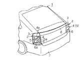
図1はストップランプ3の内部を示す模式斜視図であり、図2は図1のII−II線断面図である。リヤランプ2は車体7(図1参照)に組み付けられるハウジング9を備え、ハウジング9には開口部10を覆うように無色透明の透光部材としてのレンズ11が取り付けられている。ハウジング9の内部には光源バルブ4a〜6aの他に、ストップランプ3を構成するリフレクタ12、LED13及びエクステンション14が収容されている。
【0025】
リヤランプ2は互いに対向するリフレクタ12とLED13とで組をなし、本例では9組の発光単位からなっている。その発光単位は同図の上下方向に複数の段(本例では3段)をなすように配置され、同図の下側から順に1段目〜3段目とすると1段目が3組、2段目が2組、3段目が1組の発光単位が配置されている。また、発光単位を列で見て同図の左側から順に1列目〜3列目とすると、1列目が3組、2列目が2組、3列目が1組で配置されている。
【0026】
リフレクタ12(LED13)は1段目よりも2段目が、2段目よりも3段目がフロント側に位置するようにずれて配置されている。また、リフレクタ12(LED13)は同一段で見た場合、1列目よりも2列目が、2列目よりも3列目がフロント側に位置するようにずれて配置されている。なお、リフレクタ12が反射材、LED13が発光体、エクステンション14が映込部材に相当する。
【0027】
図2に示すように、リフレクタ12はその表面が曲面状となるように湾曲形状をなし、プラスチック製の本体部15と、本体部15の表面に配設された反射部16とを備えている。反射部16はアルミ蒸着により形成され、本体部15の表面のほぼ全域に亘って配置されている。ストップランプ3を真後ろから見たときの視線を水平軸Lとした場合、リフレクタ12は反射部16の反射面16aと水平軸Lとのなす角度θaが所定の鋭角となるように、反射面16aが下側向きに配置されている。
【0028】
LED(発光ダイオード)13はリフレクタ12の下方位置に各々配置されている。LED13は発色光が赤色であり、その発光部13aがリフレクタ12側(図2では上側)を向く状態で基板17に配置されている。車両1の運転操作においてブレーキ操作がなされると、LED13が赤色光をリフレクタ12に向かって発光し、その赤色光がリフレクタ12の反射面16aによってリヤ側に反射することによって、その反射光がレンズ11を透過して外部に照射される。
【0029】
リフレクタ12の反射面16aと対向する位置には基板17を組み付けるためのブラケット18が配設されている。基板17はネジ19を基板17の挿通孔17aに挿通して、ブラケット18の組付部18aに設けたネジ穴18bにネジ19を螺着することによってブラケット18の裏面に固定されている。ブラケット18の中央部には基板17上のLED13をブラケット18の上面側に露出するための略円形状の孔部18cが形成されている。
【0030】
複数のリフレクタ12のうち1段目及び2段目のリフレクタ12には、その裏面に左右方向に亘って延びる支持部15aが突設されている。2段目及び3段目のブラケット18は組付部18aと反対側の端部が支持部15aの上面に載置された状態となっている。リフレクタ12は下端部の裏面にネジ穴15bが形成され、組付部18aの先端に設けた挿通孔18dにネジ20を挿通してネジ穴15bに螺着することでブラケット18に組み付けられている。
【0031】
図1に示すように、エクステンション14はハウジング9の形状に合わせて内部に空間を有するとともに、リヤ側が開口した形状をなしている。また、エクステンション14は例えばプラスチック等の樹脂を材質とし、表面全体が黒色に着色されている。エクステンション14は各リフレクタ12の周囲を囲むような形状に形成されている。
【0032】
以下に詳述すると、エクステンション14の本体部14aには1段目と2段目のリフレクタ12の上方位置に、リヤ側に突出する略板状の平板部21が一体形成されている。このため、上段の平板部21の内面の下側に下段のリフレクタ12が位置した状態となる。エクステンション14の底部22(図1参照)及び平板部21は階段状をなすように配置されている。平板部21及び底部22は同じ段のLED13に対し水平方向に並んだ状態に配置され、LED13の光の照射経路を確保するためにLED13側の端部に切欠部21a,22aが形成されている。
【0033】
また、エクステンション14の本体部14aにはリフレクタ12を側方から覆うための壁部23が各列毎に一体形成されている。エクステンション14の平板部21、底部22、壁部23及び内壁面24はLED13の消灯時、リフレクタ12の反射面16aに自身の色を映り込ませる部材として機能する。従って、エクステンション14が黒色の場合、この黒色がリフレクタ12に映り込むことによって消灯時のストップランプ3は黒色に見える。なお、平板部21及び底部22が延出部を構成する。
【0034】
図2に示すように、LED13は平板部21の表面21bよりも下側に配置され、本例では表面21bの高さ位置から距離Hだけ下側に配置されている。距離Hは水平軸Lを基準に斜め上方からストップランプ3の内部を覗いてもLED13が見えない距離に設定されている。また、図示しないが底部22側に位置するLED13も、平板部21と同様に表面22bの高さ位置から距離Hだけ下側に配置されている。
【0035】
また、リヤランプ2の内部を覗き込む目視位置Pが水平軸Lに対して斜め上方である場合、LED13はその目視位置Pと平板部21(底部22)のLED13側の端部25とを結ぶ視線経路Rよりも下側に位置した状態であるとも言える。このため、発光部13aの頂部と端部25とを結ぶ経路Sと水平軸Lとがなす角度を最大角度θmax とした場合、斜め上方からストップランプ3を覗き込んだときの角度θbが最大角度θmax を超えない範囲であればLED13が見えない構造である。
【0036】
エクステンション14の取付手順としては、まずLED13が実装された基板17をネジ19によってブラケット18に取り付け、基板17の取付後、各列単位でそのブラケット18をネジ20によってリフレクタ12に取り付ける。そして、そのリフレクタ12をネジ(図示省略)によって各列毎にハウジング9に固着し、そこにエクステンション14を組み付けることでストップランプ3が組み立てられる。
【0037】
次に、前記のように構成されたストップランプ3の作用を説明する。
運転者が車両1に乗り込んでブレーキ操作がなされて、LED13が点灯するとLED13の赤色光がリフレクタ12の反射面16aに向けて照射される。そして、LED13からの光はリフレクタ12でリヤ側に向かうように反射され、その反射光C1が透明のレンズ11を透過して外部に照射される。従って、ストップランプ3が赤色に見えることになり、後続車に対しブレーキが踏まれたことが伝えられる。
【0038】
一方、LED13の消灯時にはエクステンション14の黒色がリフレクタ12に映り込み、この映り込み作用によってストップランプ3は全体がほぼ黒色に見える。例えば、上方からストップランプ3を見た場合には平板部21(底部22)の表面21bの黒色がリフレクタ12の反射面16aに映り込み、その映り込んだ黒色が反射色C2としてリヤ側に映し出される。また、左右方向の斜め位置からストップランプ3を見た場合には、壁部23や内壁面24の黒色がリフレクタ12に映り込んでストップランプ3が黒色に見える。
【0039】
ところで、レンズ11の外側からランプ内部のLED13が見えると、LED13自体の色(赤色)が見えてしまい、それによって消灯時におけるストップランプ3の単一色化が妨げられる。しかし、本例ではエクステンション14の平板部21及び底部22の表面21b,22bに対して距離Hだけ下側にLED13が配置されているので、レンズ11の外側からLED13が見え難くなり、消灯時のストップランプ3は全体がほぼ一色の黒色として見える。
【0040】
また、リフレクタ12をその反射面16aが上向きとなるように配置すると、反射面16aで太陽光を反射してエクステンション14の黒色が映り込まなくなり、消灯時における単一色化に支障を来す。しかし、本例ではリフレクタ12の反射面16aが下向きとなるように角度θaを付けて配置するので、反射面16aが太陽光を反射せず反射面16aにエクステンション14の黒色を映り込ませることが可能となり、消灯時のストップランプ3が一色の黒色として見え易くなる。
【0041】
本例では、エクステンション14に平板部21及び底部22を設け、その表面21b,22bの高さ位置よりもLED13を距離Hだけ下側に配置したので、外側からストップランプ3を見たときにLED13が見え難くなり、消灯時におけるストップランプ3の単一色化が図れる。また、リフレクタ12を反射面16aが下向きとなるように配置したので、太陽光等に邪魔されずにエクステンション14の黒色をリフレクタ12に映り込ませることが可能となり、消灯時のストップランプ3の単一色化に一層寄与する。
【0042】
従って、この実施形態では以下のような効果を得ることができる。
(1)エクステンション14に平板部21及び底部22を設け、平板部21及び底部22の表面(上面)21b,22bに対して距離Hだけ下側にLED13が配置されているので、外側からストップランプ3の内部を見てもLED13が平板部21や底部22に隠れて見え難くなる。従って、例えばLED13の発光部13aが赤色に着色されていても、LED13の消灯時にはストップランプ3がほぼ黒一色に見え、消灯時におけるストップランプ3の単一色化を図ることができる。
【0043】
(2)リフレクタ12をその反射面16aが下向きとなるように角度θaを付けて配置するので、反射面16aが太陽光を反射し難くなり、これに伴って反射面16aにエクステンション14の黒色を映り込ませることができる。よって、消灯時のストップランプ3をほぼ一色の黒色として見え易くすることができる。
【0044】
(3)平板部21及び壁部23がエクステンション14の本体部14aに対して一体形成されているので、例えば平板部21や壁部23が本体部14aと別部品である場合に比べてハウジング9への組付工程が減らすことができ、組付工程の作業が楽になる。
【0045】
(4)リフレクタ12とLED13とが各々組をなして複数形成されるので、発光源が複数存在することになり、高輝度の光をストップランプ3から照射することができる。
【0046】
(5)LED13から照射された赤色光はリフレクタ12で反射された後、直ぐにレンズ11を通過して外部に照射される。従って、消灯時の色を映り込ませるための比較的肉厚の厚いインナーレンズ58(図6参照)等を介することがないので、光の減衰が少なくて済み、結果として高輝度の光をストップランプ3から照射することができる。
【0047】
(6)LED13は例えば光源バルブ等に比べて小さいので、外側からストップランプ3を覗いてもLED13が見え難くなり、消灯時におけるストップランプ3の単一色化に一層寄与する。
【0048】
(7)上段の平板部21の内面の下側に下段のリフレクタ12が配置されているので、上段ではその平板部21が消灯時に自身の色を映り込ませる部材として機能し、下段では太陽光を遮る庇の機能を担う。従って、1つの平板部21で2つの機能を満たせることになり、部品点数の低減化が図れる。
【0049】
なお、実施形態は前記に限定されず、例えば次の態様に変更してもよい。
○ LED13は発光部13aがリフレクタ12の反射面16a側を向く配置位置であることに限定されない。例えば図4に示すように、発光部13aが下側を向くようにLED13を配置し、リフレクタ12(反射面16a)を半円状にして、LED13からの光を反射面16aで複数回反射させて外部に照射する構成でもよい。
【0050】
○ リフレクタ12は反射面16aが下向きであることに限らず、例えば図5に示すように反射面16aが上向きである構成としてもよい。この場合、リフレクタ12に太陽光が射し込まないように、反射面16aに対向するエクステンション14の平板部21を充分な長さとする必要がある。
【0051】
○ リフレクタ12の反射面16aの向きは上向き又は下向きに限定されない。例えば、図5に示す縦軸又は横軸を中心軸にして回転させることによって、所定角度傾いた向きに配置してもよい。
【0052】
○ 信号灯具はストップランプ3に限らず、例えばターンシグナルランプ4、バックアップランプ5、テールランプ6等の他のランプでもよい。また、リヤランプ2は各種ランプ3〜6が一体となった構成に限らず、各々が別々でもよいし、所定のものを組み合わせた構成でもよい。
【0053】
○ 信号灯具はストップランプ3や実施形態中に記載の各種ランプ4〜6に限らず、例えばヘッドランプやフロント側のターンシグナルランプ等に用いてもよい。また、レンズ11は無色透明に限らず、赤色や黄色等の有色透明でもよい。
【0054】
○ エクステンション14は平板部21や壁部23が本体部14aと一体であることに限らず、平板部21及び壁部23が本体部14aに対し別体である構成としてもよい。また、エクステンション14の形状は平板部21及び壁部23を有する形状に限らず、LED13の消灯時に自身の色をリフレクタ12に映し込むことが可能で、LED13を見え難くする形状であればよい。
【0055】
○ リフレクタ12はアルミ蒸着により反射面16aが形成される構成に限らず、例えば銀色塗装によって形成される構成でもよい。
○ エクステンション14は黒色に限らず、車両1の車体色に合わせて灰色、黄色、青色、緑色等を用いてもよく、その色は特に限定されない。
【0056】
○ LED13の発光色は赤色に限らず、黄色や白色等を用いてもよく、発光色は特に限定されない。また、発光体はLED13に限らず、例えば発光バルブを用いてもよい。
【0057】
○ 平板部21(底部22)の表面21b(22b)と発光部13aとの間の距離Hは適宜変更してもよい。また、ストップランプ3を上方から覗き込んだとき、LED13が見えない最大角度θmax も適宜変更してもよい。
【0058】
○ 延出部は平板状の平板部21や底部22に限らず、例えばブロック状や屈曲形状等でもよく、LED13を隠す形状であればその形状は特に限定されない。
【0059】
○ リフレクタ12とLED13との組数は9組に限らず、例えば1組や10組、20組等の9組以外の数値の組数を用いてもよい。
○ 信号灯具は車両1に搭載されることに限らず、例えば電気機器、ロボット等の運転者の操作に応じた信号を点灯(点滅)させる必要のあるものであれば特に限定されない。
【0060】
前記実施形態及び別例から把握できる技術的思想について、以下にその効果とともに記載する。
(1)請求項1〜7において、所定の傾斜を持って斜めから前記透光部材を見たときの目視位置と、前記映込部材の発光体側の端部とを結ぶ視線経路よりも下側に前記発光体を配置した。
【0061】
(2)請求項8において、前記映込部材には前記発光体よりも透光部材側に延出部が設けられ、前記発光体は前記延出部の表面に対して前記反射材の反射面から離間する側に配置されている。
【0062】
(3)請求項8及び前記技術的思想(2)において、前記反射材の前記反射面を被取付部に対する取付状態のときに所定角度を持たせて下向きとした。
(4)前記技術的思想(2),(3)において、前記延出部は前記映込部材の本体部に対して一体形成されている。
【0063】
(5)前記技術的思想(2)〜(4)において、前記発光体と前記反射材とが各々組をなして複数形成され、隣接する組同士のうち一方の組の前記延出部の内面側に他方の組の前記反射材が配置されている。
【0064】
(6)請求項8及び前記技術的思想(2)〜(5)において、前記発光体はその発光部が反射材側を向いて配置されている。
(7)請求項8及び前記技術的思想(2)〜(6)において、前記発光体はLEDである。
【0065】
【発明の効果】
以上詳述したように本発明によれば、斜め位置から透光部材の内側を見たときに映込部材によって隠れる位置に発光体を配置したので、外側から信号灯具の内部を見ても発光体が映込部材に隠れて見え難くなり、消灯時における信号灯具の通常色がほぼ単一色に見える。
【図面の簡単な説明】
【図1】一実施形態におけるストップランプの内部を示す模式斜視図。
【図2】図1のII−II線断面図。
【図3】車両を後方から見た模式斜視図。
【図4】別例におけるストップランプの部分拡大模式断面図。
【図5】他の別例におけるストップランプの部分拡大模式断面図。
【図6】従来の車両用信号灯具の模式断面図。
【符号の説明】
3…信号灯具としてのストップランプ、7…被取付部としての車体、11…透光部材としてのレンズ、12…反射材としてのリフレクタ、13…発光体としてのLED、13a…発光部、14…映込部材としてのエクステンション、14a…本体部、16a…反射面、21…延出部を構成する平板部、22…延出部を構成する底部、21b,22b…表面、C1…反射光。[0001]
TECHNICAL FIELD OF THE INVENTION
The present invention relates to a signal lamp for projecting a predetermined color according to an operation content of an operator and a reflection structure of the signal lamp.
[0002]
[Prior art]
2. Description of the Related Art Conventionally, vehicles are equipped with vehicle lamps such as tail / stop lamps, rear turn signal lamps, and backup lamps. An example of this type of vehicular lamp is disclosed in Patent Document 1, for example, and FIG. 6 is a longitudinal sectional view of the
[0003]
The
[0004]
A colorless and transparent
[0005]
Here, when the
[0006]
When the viewing angle (viewing direction) when the
[0007]
On the other hand, when the
[0008]
[Patent Document 1]
JP-A-2000-71862 (pages 3-5, FIG. 1)
[0009]
[Problems to be solved by the invention]
However, in the
[0010]
Further, in Patent Document 1, even when external light such as sunlight is incident upon turning off the light, the external light is attenuated while passing through the
[0011]
The present invention has been made in view of the above-described problems, and its object is to provide a signal lamp and a normal color that can be seen when turned off and a functional color that can be seen when turned on, respectively. An object of the present invention is to provide a reflecting structure of a signal light.
[0012]
[Means for Solving the Problems]
In order to achieve the above object, according to the first aspect of the present invention, a luminous body that emits light of a predetermined color, a reflecting material that reflects the light of the luminous body, and a color different from a color when the luminous body is turned on And a light-transmitting member that covers the light-emitting body, the reflector, and the light-emitting member from outside and transmits the reflected light of the reflector, and a predetermined angle. The luminous body was arranged at a position hidden by the projection member when the inside of the translucent member was viewed from the oblique position provided.
[0013]
According to the present invention, when the light emitter is turned on (blinks), a color (functional color) based on the light emitter is obtained, and when the light emitter is turned off, a color different from the functional color reflected on the reflector is obtained. The color (normal color) of the projection member is obtained. In addition, since the luminous body is located at a position that is hidden by the projection member when viewing the inside of the light-transmitting member from an oblique position, the luminous body is hidden behind the projection member even when viewing the inside of the signal light from outside. It becomes difficult. Therefore, for example, even if the light-emitting portion of the light-emitting body is colored, the signal light at the time of turning off the light looks like a substantially normal color of the light-emitting portion, and the signal lamp at the time of turning off can be made a single color.
[0014]
According to a second aspect of the present invention, in the first aspect of the present invention, the projection member includes an extending portion located closer to the light transmitting member than the luminous body, and the luminous body is formed of the extending portion. The reflection member is disposed on the side of the reflection member that is separated from the reflection surface. According to the present invention, since the luminous body is arranged on the side away from the reflecting surface of the reflecting member with respect to the surface of the extension portion forming a part of the projection member, if the distance is widened, the signal is increased. The luminous body becomes more difficult to see when looking inside the lamp.
[0015]
According to a third aspect of the present invention, in the first or second aspect of the present invention, the reflecting surface of the reflecting material is directed downward at a predetermined angle when the reflecting surface is attached to the attached portion. According to this invention, in addition to the effect of the invention described in
[0016]
According to a fourth aspect of the present invention, in the second or third aspect of the invention, the extending portion is formed integrally with the main body of the projection member. According to this invention, in addition to the effect of the invention described in
[0017]
In the invention described in
[0018]
In the invention described in
[0019]
In the invention described in claim 7, in addition to the function of the invention described in any one of claims 1 to 7, the luminous body is an LED. According to this invention, in addition to the effect of the invention described in any one of claims 1 to 7, since the LED is smaller than, for example, a light source bulb or the like, the use of the LED as the light emitter further increases the light emitter. It becomes harder to see and further contributes to a single color of the signal light when turned off.
[0020]
In the invention according to claim 8, when the illuminant is turned on, the light is reflected by a reflector, and the reflected light is radiated to the outside via a light transmitting member covering the illuminator and the reflector. When the light-emitting body is turned off, the color of the projection member arranged in parallel to the light-emitting body is reflected on the reflecting material to project a color different from the light-emitting body, and from a diagonal position having a predetermined angle. The light emitter was arranged at a position hidden by the projection member when the inside of the light transmitting member was viewed. According to this invention, the same operation as the first aspect is obtained.
[0021]
BEST MODE FOR CARRYING OUT THE INVENTION
Hereinafter, an embodiment in which the present invention is embodied in a vehicle signal lamp will be described with reference to FIGS.
[0022]
FIG. 3 is a schematic perspective view of the vehicle 1 as viewed from the rear. A pair of left and right rear lamps (combination lamps) 2 are disposed on the back of the vehicle 1. The
[0023]
The
[0024]
FIG. 1 is a schematic perspective view showing the inside of the
[0025]
The
[0026]
The reflectors 12 (LEDs 13) are displaced so that the second stage is located on the front side of the first stage and the third stage is located on the front side of the second stage. Further, the reflectors 12 (LEDs 13) are arranged so as to be shifted so that the second row is located on the front side from the first row, and the third row is located on the front side from the second row. The
[0027]
As shown in FIG. 2, the
[0028]
The LEDs (light emitting diodes) 13 are respectively arranged at positions below the
[0029]
A
[0030]
Each of the first and
[0031]
As shown in FIG. 1, the
[0032]
More specifically, a substantially plate-shaped
[0033]
Further, a wall portion 23 for covering the
[0034]
As shown in FIG. 2, the
[0035]
When the viewing position P looking into the inside of the
[0036]
As a procedure for attaching the
[0037]
Next, the operation of the
When the driver gets into the vehicle 1 and performs a brake operation to turn on the
[0038]
On the other hand, when the
[0039]
By the way, when the
[0040]
Further, if the
[0041]
In this example, since the
[0042]
Therefore, in this embodiment, the following effects can be obtained.
(1) Since the
[0043]
(2) Since the
[0044]
(3) Since the
[0045]
(4) Since a plurality of
[0046]
(5) The red light emitted from the
[0047]
(6) Since the
[0048]
(7) Since the
[0049]
The embodiment is not limited to the above, and may be changed to, for example, the following mode.
The
[0050]
The
[0051]
The direction of the
[0052]
The signal lamp is not limited to the
[0053]
The signal lamp is not limited to the
[0054]
The
[0055]
The
The
[0056]
The emission color of the
[0057]
(Circle) the distance H between the
[0058]
The extending portion is not limited to the
[0059]
The number of pairs of the
The signal light is not limited to being mounted on the vehicle 1 and is not particularly limited as long as it needs to light (blink) a signal according to the operation of a driver such as an electric device or a robot.
[0060]
The technical ideas that can be grasped from the embodiment and other examples will be described below together with their effects.
(1) In claim 1 to 7, below a line of sight connecting a visual position when the translucent member is viewed obliquely with a predetermined inclination and an end of the projection member on the light emitting body side. The luminous body was arranged in the above.
[0061]
(2) In Claim 8, the projection member is provided with an extension on the light-transmitting member side of the illuminant, and the illuminant is a reflection surface of the reflection material with respect to a surface of the extension. It is located on the side away from the.
[0062]
(3) In claim 8 and the technical concept (2), the reflecting surface of the reflecting material is downwardly directed at a predetermined angle when the reflecting surface is attached to the attached portion.
(4) In the technical ideas (2) and (3), the extension is integrally formed with the main body of the projection member.
[0063]
(5) In the technical ideas (2) to (4), a plurality of the luminous bodies and the reflective material are formed in pairs, and an inner surface of the extension portion of one of adjacent pairs. The other set of said reflectors is arranged on the side.
[0064]
(6) In claim 8 and the technical ideas (2) to (5), the luminous body is arranged such that a luminous portion thereof faces the reflective material side.
(7) In claim 8 and the technical ideas (2) to (6), the luminous body is an LED.
[0065]
【The invention's effect】
As described in detail above, according to the present invention, the luminous body is arranged at a position that is hidden by the projection member when viewing the inside of the light transmitting member from an oblique position. The body is hidden by the projection member, making it difficult to see, and the normal color of the signal lamp at the time of turning off the light looks almost single color.
[Brief description of the drawings]
FIG. 1 is a schematic perspective view showing the inside of a stop lamp according to an embodiment.
FIG. 2 is a sectional view taken along line II-II of FIG.
FIG. 3 is a schematic perspective view of the vehicle as viewed from the rear.
FIG. 4 is a partially enlarged schematic cross-sectional view of a stop lamp in another example.
FIG. 5 is a partially enlarged schematic cross-sectional view of a stop lamp in another example.
FIG. 6 is a schematic cross-sectional view of a conventional vehicle signal lamp.
[Explanation of symbols]
DESCRIPTION OF
Claims (8)
所定角度を持たせた斜め位置から前記透光部材の内側を見たときに、前記映込部材によって隠れる位置に前記発光体を配置した信号灯具。A luminous body that emits light of a predetermined color, a reflector that reflects the light of the luminous body, and a projection member that reflects the color of the luminous body that is different from the color when the luminous body is turned on to the reflective material when the light is turned off. A light-transmissive member that covers the light-emitting body, the reflective material and the projection member from outside, and transmits the reflected light of the reflective material,
A signal lamp in which the luminous body is arranged at a position hidden by the projection member when the inside of the light transmitting member is viewed from an oblique position having a predetermined angle.
前記発光体の消灯時には前記発光体に並設された映込部材の色を前記反射材に映り込ませて前記発光体と異なる色を映し出し、所定角度を持たせた斜め位置から前記透光部材の内側を見たときに、前記映込部材によって隠れる位置に前記発光体を配置した信号灯具の反射構造。When the light emitter is turned on, the light is reflected by a reflector, and the signal light is a reflection structure for irradiating the reflected light to the outside via a light transmitting member that covers the light emitter and the reflector.
When the light-emitting body is turned off, the color of the projection member arranged in parallel with the light-emitting body is reflected on the reflecting material to project a color different from that of the light-emitting body, and the light-transmitting member is obliquely positioned at a predetermined angle. The reflection structure of a signal lamp in which the luminous body is arranged at a position where the luminous body is hidden by the projection member when viewing the inside of the light emitting device.
Priority Applications (1)
| Application Number | Priority Date | Filing Date | Title |
|---|---|---|---|
| JP2003054085A JP2004265697A (en) | 2003-02-28 | 2003-02-28 | Signal lamp and reflecting structure of signal lamp fitting |
Applications Claiming Priority (1)
| Application Number | Priority Date | Filing Date | Title |
|---|---|---|---|
| JP2003054085A JP2004265697A (en) | 2003-02-28 | 2003-02-28 | Signal lamp and reflecting structure of signal lamp fitting |
Publications (1)
| Publication Number | Publication Date |
|---|---|
| JP2004265697A true JP2004265697A (en) | 2004-09-24 |
Family
ID=33118521
Family Applications (1)
| Application Number | Title | Priority Date | Filing Date |
|---|---|---|---|
| JP2003054085A Pending JP2004265697A (en) | 2003-02-28 | 2003-02-28 | Signal lamp and reflecting structure of signal lamp fitting |
Country Status (1)
| Country | Link |
|---|---|
| JP (1) | JP2004265697A (en) |
Cited By (15)
| Publication number | Priority date | Publication date | Assignee | Title |
|---|---|---|---|---|
| JP2007059075A (en) * | 2005-08-22 | 2007-03-08 | Stanley Electric Co Ltd | Vehicular lighting fixture |
| JP2007103210A (en) * | 2005-10-05 | 2007-04-19 | Honda Motor Co Ltd | Vehicular direction indicator lamp |
| JP2008047455A (en) * | 2006-08-18 | 2008-02-28 | Koito Mfg Co Ltd | Vehicular lamp |
| WO2009110080A1 (en) * | 2008-03-06 | 2009-09-11 | 本田技研工業株式会社 | Taillight unit |
| CN101566296B (en) * | 2008-04-23 | 2010-11-17 | 市光工业株式会社 | Lamp fitting for vehicle |
| WO2012176652A1 (en) * | 2011-06-21 | 2012-12-27 | コニカミノルタアドバンストレイヤー株式会社 | Vehicle headlight |
| WO2013065116A1 (en) * | 2011-10-31 | 2013-05-10 | 日立コンシューマエレクトロニクス株式会社 | Backlight device and liquid crystal display device utilizing same |
| ITPD20130352A1 (en) * | 2013-12-20 | 2015-06-21 | Automotive Lighting Italia Spa | LIGHTING AND / OR SIGNALING DEVICE FOR VEHICLES |
| JP2015112954A (en) * | 2013-12-10 | 2015-06-22 | マツダ株式会社 | Vehicle head light |
| JPWO2013132764A1 (en) * | 2012-03-08 | 2015-07-30 | 株式会社小糸製作所 | Vehicle lighting |
| JP2017204343A (en) * | 2016-05-10 | 2017-11-16 | 川崎重工業株式会社 | Vehicle head lamp device |
| JP2018101626A (en) * | 2016-12-19 | 2018-06-28 | ドクター エンジニール ハー ツェー エフ ポルシェ アクチエンゲゼルシャフトDr. Ing. h.c. F. Porsche Aktiengesellschaft | Lamp for motor vehicle body |
| US10663139B2 (en) | 2015-09-14 | 2020-05-26 | Koito Manufacturing Co., Ltd. | Vehicular lamp |
| KR20210082956A (en) * | 2019-12-26 | 2021-07-06 | 에스엘 주식회사 | Lamp for vehicle |
| IT202000000979A1 (en) * | 2020-01-20 | 2021-07-20 | Marelli Automotive Lighting Italy S P A Con Socio Unico | TERSA LENS LIGHTING DEVICE FOR VEHICLES |
-
2003
- 2003-02-28 JP JP2003054085A patent/JP2004265697A/en active Pending
Cited By (25)
| Publication number | Priority date | Publication date | Assignee | Title |
|---|---|---|---|---|
| JP4697951B2 (en) * | 2005-08-22 | 2011-06-08 | スタンレー電気株式会社 | Vehicle tail lamp |
| JP2007059075A (en) * | 2005-08-22 | 2007-03-08 | Stanley Electric Co Ltd | Vehicular lighting fixture |
| JP2007103210A (en) * | 2005-10-05 | 2007-04-19 | Honda Motor Co Ltd | Vehicular direction indicator lamp |
| JP4594205B2 (en) * | 2005-10-05 | 2010-12-08 | 本田技研工業株式会社 | Direction indicator lights for vehicles |
| JP2008047455A (en) * | 2006-08-18 | 2008-02-28 | Koito Mfg Co Ltd | Vehicular lamp |
| JP4704296B2 (en) * | 2006-08-18 | 2011-06-15 | 株式会社小糸製作所 | Vehicle lighting |
| WO2009110080A1 (en) * | 2008-03-06 | 2009-09-11 | 本田技研工業株式会社 | Taillight unit |
| EP2261555A4 (en) * | 2008-03-06 | 2011-03-02 | Honda Motor Co Ltd | Taillight unit |
| EP2261555A1 (en) * | 2008-03-06 | 2010-12-15 | Honda Motor Co., Ltd. | Taillight unit |
| US8313223B2 (en) | 2008-03-06 | 2012-11-20 | Honda Motor Co., Ltd. | Taillight apparatus |
| JP5266233B2 (en) * | 2008-03-06 | 2013-08-21 | 本田技研工業株式会社 | Tail light equipment |
| CN101566296B (en) * | 2008-04-23 | 2010-11-17 | 市光工业株式会社 | Lamp fitting for vehicle |
| WO2012176652A1 (en) * | 2011-06-21 | 2012-12-27 | コニカミノルタアドバンストレイヤー株式会社 | Vehicle headlight |
| WO2013065116A1 (en) * | 2011-10-31 | 2013-05-10 | 日立コンシューマエレクトロニクス株式会社 | Backlight device and liquid crystal display device utilizing same |
| JPWO2013132764A1 (en) * | 2012-03-08 | 2015-07-30 | 株式会社小糸製作所 | Vehicle lighting |
| JP2015112954A (en) * | 2013-12-10 | 2015-06-22 | マツダ株式会社 | Vehicle head light |
| ITPD20130352A1 (en) * | 2013-12-20 | 2015-06-21 | Automotive Lighting Italia Spa | LIGHTING AND / OR SIGNALING DEVICE FOR VEHICLES |
| US10663139B2 (en) | 2015-09-14 | 2020-05-26 | Koito Manufacturing Co., Ltd. | Vehicular lamp |
| JP2017204343A (en) * | 2016-05-10 | 2017-11-16 | 川崎重工業株式会社 | Vehicle head lamp device |
| JP2018101626A (en) * | 2016-12-19 | 2018-06-28 | ドクター エンジニール ハー ツェー エフ ポルシェ アクチエンゲゼルシャフトDr. Ing. h.c. F. Porsche Aktiengesellschaft | Lamp for motor vehicle body |
| US10288250B2 (en) | 2016-12-19 | 2019-05-14 | Dr. Ing. H.C. F. Porsche Aktiengesellschaft | Lamp for a motor vehicle body |
| KR20210082956A (en) * | 2019-12-26 | 2021-07-06 | 에스엘 주식회사 | Lamp for vehicle |
| KR102322478B1 (en) * | 2019-12-26 | 2021-11-05 | 에스엘 주식회사 | Lamp for vehicle |
| IT202000000979A1 (en) * | 2020-01-20 | 2021-07-20 | Marelli Automotive Lighting Italy S P A Con Socio Unico | TERSA LENS LIGHTING DEVICE FOR VEHICLES |
| EP3851738A1 (en) * | 2020-01-20 | 2021-07-21 | Marelli Automotive Lighting Italy S.p.A. Con Socio Unico | Clear lens lighting device for vehicles |
Similar Documents
| Publication | Publication Date | Title |
|---|---|---|
| US6986594B2 (en) | Lighting device for motor vehicles | |
| KR101684117B1 (en) | Mood lamp for vehicle | |
| JP2014175199A (en) | Vehicular lighting fixture and rear panel of vehicle | |
| KR20030015865A (en) | Vehicle lamp | |
| JP2006236588A (en) | Optical llumination device and vehicular lighting fixture | |
| JP2004265697A (en) | Signal lamp and reflecting structure of signal lamp fitting | |
| JP2004055482A (en) | Lighting fixture for vehicle | |
| JPH08124408A (en) | Light for vehicle | |
| JPH1031905A (en) | Marker lamp for vehicle | |
| JP2010050008A (en) | Lighting fixture | |
| JP2003068115A (en) | Luminaire for vehicle | |
| CN210069733U (en) | Optical system for car lamp and tail lamp | |
| JP2008522371A (en) | Hybrid optical system for LED lamps | |
| CN210069734U (en) | Optical system for car lamp and tail lamp | |
| JP5379642B2 (en) | Vehicle lighting | |
| TWM531399U (en) | Auto taillight | |
| JPH0589703A (en) | Vehicle lighting fixture | |
| JP2000251505A (en) | Vehicle marker light | |
| JP5563210B2 (en) | Lamp | |
| JPS6242408Y2 (en) | ||
| KR100817396B1 (en) | The Side mirror Having an Direction Light | |
| CN216383992U (en) | Side direction reflection of light cup system | |
| CN215636782U (en) | Reading lamp and vehicle thereof | |
| JP7324090B2 (en) | Vehicle indicator light | |
| TWM519087U (en) | Auto taillight |
Legal Events
| Date | Code | Title | Description |
|---|---|---|---|
| A621 | Written request for application examination |
Free format text: JAPANESE INTERMEDIATE CODE: A621 Effective date: 20050830 |
|
| A977 | Report on retrieval |
Free format text: JAPANESE INTERMEDIATE CODE: A971007 Effective date: 20080313 |
|
| A131 | Notification of reasons for refusal |
Free format text: JAPANESE INTERMEDIATE CODE: A131 Effective date: 20080318 |
|
| A521 | Written amendment |
Free format text: JAPANESE INTERMEDIATE CODE: A523 Effective date: 20080519 |
|
| A02 | Decision of refusal |
Free format text: JAPANESE INTERMEDIATE CODE: A02 Effective date: 20080610 |