JP4580100B2 - Timber harvesting method and forest management system - Google Patents
Timber harvesting method and forest management system Download PDFInfo
- Publication number
- JP4580100B2 JP4580100B2 JP2000519989A JP2000519989A JP4580100B2 JP 4580100 B2 JP4580100 B2 JP 4580100B2 JP 2000519989 A JP2000519989 A JP 2000519989A JP 2000519989 A JP2000519989 A JP 2000519989A JP 4580100 B2 JP4580100 B2 JP 4580100B2
- Authority
- JP
- Japan
- Prior art keywords
- timber
- marking
- harvester
- piece
- information
- Prior art date
- Legal status (The legal status is an assumption and is not a legal conclusion. Google has not performed a legal analysis and makes no representation as to the accuracy of the status listed.)
- Expired - Fee Related
Links
Images


Classifications
-
- A—HUMAN NECESSITIES
- A01—AGRICULTURE; FORESTRY; ANIMAL HUSBANDRY; HUNTING; TRAPPING; FISHING
- A01G—HORTICULTURE; CULTIVATION OF VEGETABLES, FLOWERS, RICE, FRUIT, VINES, HOPS OR SEAWEED; FORESTRY; WATERING
- A01G23/00—Forestry
- A01G23/02—Transplanting, uprooting, felling or delimbing trees
- A01G23/08—Felling trees
-
- A—HUMAN NECESSITIES
- A01—AGRICULTURE; FORESTRY; ANIMAL HUSBANDRY; HUNTING; TRAPPING; FISHING
- A01G—HORTICULTURE; CULTIVATION OF VEGETABLES, FLOWERS, RICE, FRUIT, VINES, HOPS OR SEAWEED; FORESTRY; WATERING
- A01G23/00—Forestry
- A01G23/02—Transplanting, uprooting, felling or delimbing trees
- A01G23/099—Auxiliary devices, e.g. felling wedges
-
- G—PHYSICS
- G01—MEASURING; TESTING
- G01S—RADIO DIRECTION-FINDING; RADIO NAVIGATION; DETERMINING DISTANCE OR VELOCITY BY USE OF RADIO WAVES; LOCATING OR PRESENCE-DETECTING BY USE OF THE REFLECTION OR RERADIATION OF RADIO WAVES; ANALOGOUS ARRANGEMENTS USING OTHER WAVES
- G01S19/00—Satellite radio beacon positioning systems; Determining position, velocity or attitude using signals transmitted by such systems
- G01S19/01—Satellite radio beacon positioning systems transmitting time-stamped messages, e.g. GPS [Global Positioning System], GLONASS [Global Orbiting Navigation Satellite System] or GALILEO
- G01S19/13—Receivers
- G01S19/14—Receivers specially adapted for specific applications
Abstract
Description
【0001】
(発明の背景)
本発明は、材木収穫方法および森林管理システムに関する。
【0002】
従来の材木収穫およびそれに関する作業は、材木素材がばら荷製品(bulk product)として取り扱われるという意味で、比較的原始的に行われている。立木の評価が収穫の準備として行われるとしても、それはむしろ粗雑なものである。したがって、収穫の実際の成果は、理論的に計算された成果とはかなり異なっている。今日の材木収穫技術のさらなる問題は、木材の一人の売手と一人の買手が収穫にかかわるとい意味で、材木収穫が比較的小さな規模で行われる傾向があるということである。異なる森林所有者間の境界は注意深く考慮されなければならない。これは、森林の素材は詳細に確認することができないという事実の結果である。さらに、現在の収穫機の操縦者は、森林作業を行うとき支援者が少ないことは事実である。一般に収穫機にはクロスカット(cross−cut)コンピュータがあるが、このコンピュータは、収穫機の収穫配置と木との間の接触以外は、処理中に、木と接触することはない。したがって、クロスカット作業の精度が向上すると言うだけの明確な理由はない。
【0003】
前述の欠点のため、相当な失費を伴う。多大な手動の計画と管理作業が要求される。
【0004】
(発明の説明)
本発明の目的は、森林収穫およびその計画の合理化のための条件を創設することを主としている。
【0005】
第1の局面によると、本発明は、収穫の現実の結果を考慮して、合理的な方法で収穫計画を訂正する可能性を向上することを目的としている。
【0006】
第2の局面によると、本発明は、収穫機の運転者のための改良されたコンピュータ支援を行う条件を創出することを目的としている。収穫機の完全自動制御が第1に意図されている。
【0007】
第3の局面によると、本発明は、出所不明のばら荷製品としてではなく、出所が識別された製品として、材木素材を取り扱う条件を創出することを目的としている。
【0008】
第4の局面によると、本発明は、材木片の処理チェーン(processing chain)の終りで、材木片の現実の利用度に関する情報を抽出することによる収穫計画のより良いフォローアップを創出することを目的としている。
【0009】
第5の局面によると、本発明は、収穫機により処理された材木片を地形上で探し当てることに関連する問題を減少することを目的としている。そのような位置測定はたいてい運送業者によって行われるが、その仕事は材木を森林の外に搬送することである。
【0010】
本発明の第1の局面は、立木の地理学的および地質学的状態を含む森林立木の特性に関する非常に詳細で正確なデータを作成することは、非常に発展した遠隔登録と分析技術において可能であるという現実に基づいている。このデータベースでは、森林立木の非常に精密で正確な再生を含むといってもよいが、個々の木は、数センチメートルの数デシメートルのオーダーの精度で、位置について決定されるようになってる。さらに、個々の木は木品質や内容に関して注意深く評価されるべきである。一例として、データベースの解像度は、林学立案者が通常のコンピュータマウスにより個々の木をクリックして回転および旋回することができ、さらにコンピュータに基づくクロスカット予測を達成できるようなものでなければならないことが言える。これに関して、本発明は、現実の収穫データのフィードバックにより収穫計画の非常に正確で迅速なフォローアップのための条件を創出することを目的としている。これに関連した本発明の局面は、請求項1で取り扱われている。
【0011】
本発明の第2の局面は、最適な開発を規定する請求項2、3に主として記載されたものによって達成され、この結果、収穫中に収穫機を自動制御することができる。本発明のこの局面は、収穫機と特に本発明により実行されるその収穫装置の正確な位置決定に基づいている。収穫計画が極めて正確であるうえ、収穫装置の位置が地形内で正確に決定可能であるので、収穫装置は、所定の木が収穫の対象となるように、予め作られた収穫計画に従って目標を定めて制御されてもよい。これにより、非常に進歩したコンピュータに基づく収穫計画の可能性が生じ、収穫木の運転者は、単なる補正の仕事をするだけであり、すなわち、収穫機およびその収穫装置を自動的に制御して選択された木を収穫するということを通常除くようになっている。
【0012】
本発明の第3の局面は、請求項4に記載されたものによって達成される。
【0013】
すなわち、本発明は、車両と該車両に搭載された収穫装置とからなる収穫機により森林の材木を収穫する方法において、木の伐採に関する収穫機の位置を決定し、当該木から得られる少なくとも1つの材木片に位置情報またはそのコードをマークし、これにより、材木片をデータベースに記憶された実際の位置情報と関連させるという解決手段を引き出している。
【0014】
これにより、取得される材木片は、当該成長場所と接続可能な個体となる。これは、個々の森林所有者は、収穫場所から材木片を搬送した後に、当該材木片が自分に属するのか他人に属するのかを確信をもって決定することができることを意味する。
【0015】
ばら荷製品から識別可能な個体への材木素材の変換は、複数の売手は製品を気楽に離したままにしておくことができるだけでなく、複数の買手は一つの同一の収穫位置で取り扱うことができるということを意味する。本発明の思想を完全に利用すると、材木片にマークされた位置情報により、材木片が正確にどの木から流出したかを述べることができる。収穫前に行われる立木の分析は、以下に説明する遠隔分析技術により正確に実行される。個々の木は、位置に関しては不明瞭に決定されるかもしれないが、材木品質や容積に関してはむしろ高精度で予測される。このような先立つ正確な分析は、ある収穫の歩留まりを予め非常に正確に計算することができることを意味する。さらに、真の収穫は、非常に目標的に制御されてもよい。これにより、正確には、収穫される木は最適結果をもって現実に収穫される。本発明によれば、収穫機に配置されたコンピュータ装置は、森林領域の事前解析から流出するデータと、該データに基づいて決定される収穫情報とに基づいて収穫機を制御し、予め収穫するように決定された木を正確に収穫するだけである。このような1本の木のレベルの高解像度は、森林の正確な登録が写真技術やその他の登録技術により行われ、これらの登録が地理学的に正しい状態に正確に調整されているならば、達成される。さらに、超高解像度は、収穫木に配置された位置決定装置に対して要求される。このような高解像度は、今日、衛星によるGPSシステム(全地球位置把握システム)により既に取得可能である。
【0016】
本発明の第4の局面によると、鋸引きして板にされる個々の材木片へのマーキングは、鋸引き前に読み取られ、このマーキング情報は記憶される。これにより、材木片から流出する板は、少なくとも原木の成長位置についての情報またはそのコードを含むマーキングを備える。これにより、材木片は成長場所と関連付けられる。容積と品質の両方に関する収穫結果の追加のチェックに対する条件が創出される。材木片からの板の実際の歩留まりについての情報と製材所での材木片に関する識別情報とを相関させることができる。これにより、個々の木の歩留まりに関する正確な結論を得ることができる。土地所有者は、森林立木の評価により森林の価値が上がる結果、経済的な歩留まりが期待されること、無能なクロスカットや他の観点からの不適切な取扱い等の結果、材木を取り扱うチェーンが実質的に低下することをチェックするという、実質的に改良された可能性を得る。
【0017】
本発明の第5の局面によると、コンピュータ装置は、処理された材木片を収穫装置から排出する時に、収穫装置の位置を決定し登録して、その位置情報をデータベースまたはその後に運送業者により材木片を引き出すときに使用されるデータキャリアに記憶するようになっている。このようにして、材木片は地域内で安全に見つけることができる。これに関して、材木片に関する位置情報は運送業者の運転者に示すことが好ましい。これにより、運送業者を材木片に移動させることができる。ある開発によると、運送業者の移動は、位置情報と予め立てられた立木の計画に基づいて、コンピュータの制御により完全に自動的に生じるように考えられている。
【0018】
事前分析と収穫が前述したような個々の木のオーダーの解像度に相当する精度で行われるときに、本発明の最適な利点が得られるとしても、本発明の思想がより小さな程度で、例えば1または数メータのオーダーの解像度で行われるときには、それよりも小さな精度の解像度を利用することができる。
【0019】
本発明によるシステムに関する特定の特徴は請求項の記載から明らかである。
【0020】
(発明の実施の形態の説明)
本発明に関連する詳細および利点は、以下に詳細に説明する。
【0021】
【発明の実施の形態】
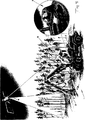
本発明の利点を完全に利用するために、森林管理における優れた決定を下すための基礎を作り出すことが必要である。一方では、土壌(地質学、第4期地質学、自然地理学、水文学、気候学、土壌学、栽培生物学、栄養地質学およびさまざまな計画地図)に関する高品質で費用効率の高い説明を確実にすることを目的とする。図1において、特に航空機からの異なった記録技術により、デジタル位相モデルにおいて正確な風景図を再生することに使用されるデータを引き出す方法が示されている。さらに、この風景図における範囲内に生育する森林が正確に記録されることが必要とされている。航空機から生育する森林を記録する異なった技術、例えば、写真測量法または写真分析技術もまたここにおいて好ましく使用される。図2aに航空写真が示され、該航空写真より1本1本の木を判別することができる。適当な写真分析技術とさまざまな種類の木の性質とそれらの異なる環境下における生息領域に関する知識とにより、個々の材木に対してその材質および体積の比較的正確な理解を得ることが可能である。実際に正確な再生技術により再生したものを実際の地図座標に一致させることによって、個々の木は、非常に高い精度、センチメートルオーダまたは少なくとも10センチメートルオーダの精度で位置に関して決定することが可能である。図2cにおいて、個々の木が判別できるように、再生技術に関して中央投影における写真の中心から外側に向かって傾けて個々の木が示されている。生育している森林材木の良好な評価は、日陰の影響、木のシルエットの円錐形、葉の大きさと針状葉の量、それらの色などを考えることによって可能となる。この評価は、収穫計画に関する非常に慎重で正確な決定の基礎となる。
【0022】
図3において、収穫計画を容易にする断面再生において、風景図と森林原木データとが合成されていることが示されている。
【0023】
図4において、符号1が付されている収穫機1は、符号2が付されているベース車両2と、該ベース車両2上に取り付けられた収穫装置3とからなることが示されている。前記収穫装置3は、本実施例ではクレーン4により前記ベース車両2に支えられている。前記収穫装置3は、いわゆるワングリップ収穫装置、すなわち立木を把持して、切断し、図4に示す状態に木を倒し、それから送り手段によってその丸太を収穫装置の内部を通過させ、同時にその丸太を枝打ち(branching)する装置である。その丸太は、切断手段によって材木片に横引き(cross-cut)されることが好ましい。強調すべきことは、本発明は、この点において、丸太の枝打ちをしないことが望まれる場合、すなわち横引きして材木片にするだけの場合にも適用可能であることである。しかしながら、本発明は、いわゆるフルログハンドリング、すなわち収穫装置が、木を切断して倒しその丸太を横引きをして小さく断片化しないで運搬するような装置に対しても適用できる。請求項において使用されている“材木”という表現は、全体として丸太を範囲に含むようにしたい場合において使用される。前記収穫装置は、望まれるならば枝打ち手段を設けて、フルログハンドリングにおいて、丸太を装置の間に通過させて、丸太から枝葉を取り除くようにしてもよい。符号5が付されている位置決定装置は、収穫機1上に設けられて、外部からの無線信号を受信する手段を用いることにより収穫機1の位置を決定することができる。前記位置決定装置は、GPSシステム(全地球位置把握システム)で構成されることが好ましい。これは、衛星を基礎とした位置検出システムであり、位置決定に関しては非常に正確に位置を検出する。衛星からの信号は、実際には外乱がある。この外乱は、実際の使用においては地上ステーションから発射される信号により補正される。これらの信号は、位置決定装置により受信され、衛星からの信号とともに求められている非常に高い位置決定精度になる。
【0024】
GPS用衛星は、図4において符号6で示され、位置決定装置5のアンテナは、符号7で示されている。拡大して示した図4の円内において、収穫機1の運転者が、位置決定装置に接続されている表示装置を用いてコンピュータ8にアクセスしている図が示されている。実際の使用において、このコンピュータ8は、位置決定所処理用のソフトウエアさらに可能であればハードウエアを備えた収穫機の横引きのこ用コンピュータであることが好ましい。
【0025】
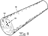
前記収穫機1には、マーキング装置が設けられている。この装置は、図9において、1つの実施例として示されて符号9が付されている。マーキング装置9は、森林から得られた材木片にマーキングすることに使用される。マーキング装置9は、コンピュータ8により制御され、位置決定装置5から受信した位置情報により、材木(例えば図8において符号10で示されている材木)にその位置情報すなわち木の生育した位置情報、もしくはこの位置情報が材木に関連付けられるコードをマーキングする。1つの材木に、1つの特別コードが与えられて、この特別コードは、材木にマーキングされ、収穫機のコンピュータに記憶されることを以下に記載する。このコードは、コンピュータに記憶されている他の情報、例えば材木の品質および/または大きさを導き出すことができるように提供されている。このコードは、例えば、異なる時期に収穫された材木を区別することができる程度の正確な時間情報を、連続する数を用いて形成することができる。このコードは、時間情報と、例えば、一本の木の材木の数によって形成された連続する数字との組み合わせによって形成することができる。重要なことは、コードが、例えば材木の生育した場所に関する位置情報や、品質および/または大きさ、生育場所に関した林学的もしくは地質学的環境と、生育場所の高度などの材木に関する記憶された他のデータに対して、ある特定の材木に関連させるための基礎として役立つことである。この生育場所の高度は、GPS装置から得られる。
【0026】
しかしながら、材木の生育場所に関する位置情報を材木片のマーキングとして付与し、そのマーキングを読むことによって、その木をデータベースから抽出しなければならない他のデータがなくても生育場所に関連付けられることは、本発明の範囲内であることが示されている。幹全てが扱われないような場合において、その木の中の該当する材木片の場所に関する数を、生育場所に関する位置情報に補足することが必要である。材木片は、さらに材木の中に読み出し可能な情報、例えば品質、大きさなどに関する情報を伴って提供されてもよい。特に、材木片に多量の情報を結合する必要がある場合、しかし、通常は材木片を1つのコードと一致させ、代わりに、データを1つまたは複数のデータベースに記憶させ、関連するデータはコードを用いて材木片に関連させることが好ましい。これに関して、材木片に関係させることができるコード手段によるさらなるデータは、実際の買い手と可能であれば売り手に関した情報であることが好ましい。
【0027】
森林の生育場所と売り手とを関連付けることが可能である場合、売り手の情報は必ずしも必要ではない。図7に示すように、収穫装置3の放出端が示され、材木の端が装置3の送り手段11によって放出されている。装置は、この放出端の場所に、供給された材木片を切断する切断手段12を有する。切断手段12は、本実施例では、回動可能に設けられ走行するチェーンを有するチェーンソーである。他の切断手段もまた可能である。本発明にかかるマーキング装置は、収穫装置の放出端に設けられることが好ましい、それにより、本実施形態によると、供給される材木片は、丸太の残りの部分から切り落とされた後すぐにマーキングすることができる。さらに、マーキングは、切り落とされる材木片の端にも行なうことができるが、それにはむしろ高速化を必要とする。しかしながら、それ以外の実施形態も十分に可能である。このように、マーキング装置は、材木片の外皮表面上に、可能であれば樹皮からその外皮表面の1部分を解放した後、マーキングを付与するようにしてもよい。他の実施形態によると、丸太の残りの部分から分離されていない材木片にマーキングすることもまた可能である。しかし、これは、それから材木片の品質と体積に関する予測をしなければならないことを意味する。もし予測が正しくない場合には、誤差が生じる可能性がある。
【0028】
材木片へのマーキングを実行するための可能性は、例えば、切断手段12に目的に適したマーキング手段を設けることにより、マーキング装置と切断手段12とを一体化することである。これらは非接触型でも接触型でも良い。可能な実施例によると、マーキング手段は、すでに切断された材木片に前述したような内容の情報を含むマークをスプレーすることに適したスプレーノズルの特性を有する。このための条件は、比較的多くの数のスプレーノズルである。これは、原則的に材木の端面全体に多量の情報内容を有するマークを付与することが可能である。より限定された情報内容もまた、コードだけにする場合に特に可能である。
【0029】
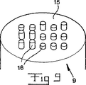
図8において、概略的に示された材木片10に、符号13で示すマーキングが設けられて、該マーキングは材木片の端面に穿設されたマトリックス状穴からなっている。マーキングは、前記マトリックスを適切に読み出すことが可能なようにする適当な基準マーク14を有している。前記マトリックス内に形成される穴の数は、多い方が好ましく、例えば100もしくは必要とされている情報量に従って100以上であることが好ましい。材木片の端面に前記マークを付与することが好ましい。その後にマーキング情報を読み出すことが容易になるからである。
【0030】
図9において、多くのマーキング部16が配設された本体部15からなるマーキング装置9が示されている。前記マーキング部16は、例えば、選択的にマーキング動作位置と待機位置との間を移動可能なパンチング手段の性質を備えている。前記パンチング手段は、例えば、突出すると作動位置にあり、後退すると非作動位置にあるようになっている。このように、パンチング手段は、材木片の端面に対して押圧され、マーキング手段が、瞬時に作動、例えば材木片の終端面内に突出するようになっている。
【0031】
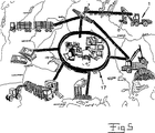
図5において、収穫組織がそれぞれ制御センター17と接続されて、電話もしくは電波などを介して収穫組織内の他のユニットとも通信することができることが示されている。収穫機は、符号1で示されている。収穫される森林に関する情報は、収穫機1のコンピュータ8から制御センター17に送信され、例えば当面の間求められている分類(assortment)に収穫が集中するように、収穫機1の収穫作業を制御するのに適した信号が、制御センター17から収穫機1に送信される。制御センタ17は、収穫組織内の輸送手段や製材所またはパルプ産業などの材木消費者のような他のユニットとも連絡されている。制御センター17は、GPSシステムを介して効果的に収穫組織のユニットの位置を記録し続け、効果的に収穫作業の計画を立案することが好ましい。制御センター17は、入手できる材木と収穫により入手できる材木の場所と、さらにそれぞれの予測される品質と量とを知ることができるデータを常に有することが好ましい、それにより、商談が、制御センターを利用して非常に迅速に成立する。別の表現をすると、制御センターは、“電子”材木取引として機能することができる。
【0032】
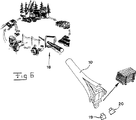
図6において、丸太10が、如何にして製材所で板材に鋸引きされる準備がされるかが示されている。鋸引き取入口18は、概略的に示されている。再生装置19は、鋸引き取入口18と組み合わされて配置され、鋸引きする前の材木の端面を再生し、記録し、形状に関するこの映像の情報、例えば直径、樹皮の厚さおよび/または年輪の幅などのような生育度などを保存することに使用されている。再生装置19を介して得られた情報により、システムに設けられた設備は、材木が産出された森林地域の時間的な成長についての分析と予測を行なうことができる。収穫計画の修正もまた起こりうる。このための条件は、もちろん、読取装置20を提供し、鋸引き取入口18に設けて、それぞれの材木のマークを読み取り、マーク情報を記憶することである。製材所に接続されているコンピュータ装置は、製材所に設けられた別のマーキング装置を制御して、材木10から得られた板材に、少なくともその木の生育した源場所に関する情報と関連するコード形式のマークを付与するようになっている。板材は、このようにして得られることが好ましい、これにより生育した場所に関して調べることが可能となり、環境保護意識を持つ買い手は、環境保護の観点から受容できる地域から産出された板材を確実に購入することができる。
【0033】
再生装置19と読取装置20は、もちろん一体のもしくは同じユニットからなることが可能である。
【0034】
材木10のマークとこのマークの読み取りは、そのマークを鋸引きした後の材木の実際の経済産出高(economical yield)に関した情報と相関させることが可能である。それから、材木の経済産出高と生育場所に関したデータは、森林データベースに既に存在する情報、すなわち、最初に森林の立木の評価のフレームにおいて得られる情報と比較され、それから収穫装置と一体に設けられたマーキング装置によって材木に付与された収穫に関する情報と比較される。
【0035】
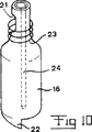
図10において、既に図9において示したマーキング部16がどのような構造であるかが示されている。パンチ機の特性を有するマーキング手段は、材木の中に押し込まれると木の一部を取り込む管形状の先端部を有している。パンチング部16は、当該パンチング部16の管形状の先端部から内側に取り込まれた木を排出することができる側面開口部21を有している。パンチング部16は、パンチング方向と平行な軸に関して回転可能に設けられている。これにより、パンチング手段の先端から中に入った木は、材木から切り離され開口部21を通過して外側に運ばれる。
【0036】
カム形状の突出部22は、パンチング部16を作動位置まで突出させるために設けられ、パンチング手段を突出させるとともに回転させるようになっている。突出部22は、その復帰時にパンチング手段を回動させて初期位置に戻す。それから、突出部22は、強制的にパンチング手段を引き込むように配置するか、または代案として(もしくは補足として)図10に示すようにバネ23が復帰動作のために役立っても良い。
【0037】
図10に示すパンチング部16をインクマーキング手段と組み合わせることも可能である。前記パンチング手段にインクチャネル24を設け、インク供給源からマーキング用インクが前記インクチャネル24を介して前記パンチング手段の先端口の所まで供給されるようにする。その目的は、パンチング後に材木の端面に形成される穴にインクを供給してそれを明瞭に見えるようにすることである。
【0038】
図11において、異なるマーキング装置9が示されている。マーキング部16は、マトリックス上に配置されるとともに回転可能に設けられた複数の比較的小さいドリルからなる。これらのドリルそれぞれは、例えば符号26が付されているギア26の中心開口部25内に収容されるようになっていることが好ましい。ギア26の外周面上には、カムベルト26aと噛み合うような歯が設けられている。前記ドリル16とギアの開口部25は、ギアに対するドリルの相対回転を防止する係合手段を有している。カムベルト27は、図11bに示す通路内を走行するとき、異なるギア26と噛み合うようになっている。これによりギア26は回転し、同時にドリル16が回転する。ドリル16は、ギア26に対して軸方向に移動可能であり、これにより、所望のドリルを図11においては図示しない軸方向移動手段によってマーキング動作位置に移動させることができる。その作用は、図9のマーキング手段において前述されたものと同様である。すなわち、その瞬間に、作動されるドリル形状のマーキング手段16は、突出され、その他のものは後退されたままである。
【0039】
図12に示すように、代案のマーキング装置9の本体15は、回転可能なホイールである。マーキング手段16は、半径方向に移動可能であり、ホイールの周縁部の開口部を介して突出することができる。さらに、駆動手段がホイール内に設けられて、これによりマーキング手段16は、選択的に突出され、所望のマークを材木に与える。図12に示すようなマーキング装置は、材木の樹皮表面に、可能であれば、樹皮を剥ぎ取ったところにもしくは樹皮を通過してもしくは樹皮上にマークするように使用される。しかし、材木の端面にマーキングする場合にこのホイール原理を適用できる。
【0040】
他のマーキング技術も当然可能である。有益なマーキング技術の1つは、丸太上に所望のマーク、例えばバーコード形式においてもしくはその他の方法により付与するレーザージェット手段の使用に基づくものである。多くのレーザーマーキング手段は、構造的な実施例に関して前述した方法でマトリックス形状に配置することができる。レーザー技術に加えてその他の放射エネルギーももちろんマーキングの手段として使用することができる。
【0041】
分離したキャリヤ上に必要とされるマーキング情報を付与し、次に当該キャリアを材木上に付与するように、マーキング装置を設計することも可能である。これは、例えばマーキング情報がバーコード形式もしくはその他のコードで設けられた細長片とすることができる。
【0042】
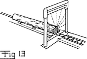
図13において、製材所の取入口に設けられた1つのクリーニング装置が示されている。このクリーニング装置は、雪や氷などのマーキング情報をより読み取りにくくする汚染物を材木から取り除くものである。このクリーニング装置は、例えばスチームシャワーの性質を有することが好ましい。マーキング情報が材木ユニットの端部のみに付けられている場合、クリーニング装置はクリーニング作業を端部において行なうことで十分である。
【0043】
図6の符号19、20により示されたような読取装置は、製材所と接続して配置する必要はないことに留意する必要がある。このような読み取り装置は、材木をその上に付与されたマークに従って分類する必要がある場合、他の場所に配置することができる。これにより、それぞれの買い手は、必要な材木を供給されることができる。マーキング技術は、一般的に、1つ1つの材木が、図5に示すような収穫システムにおいて個別に扱われることを想定しているので、買い手は、使用する分野に最も適した材木の入手を期待できる。
【0044】
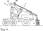
図14において、前述した位置決定装置5を備えた収穫機が示されている。図14において使用されているクレーンは図4において示したものとは異なるものである。位置決定装置5は、図4に関する実施形態と同様であり、位置決定ユニット27を車両上に、例えば本実施形態においては回転可能な運転室の上に有する。また、位置決定装置は、位置決定ユニット27に対する収穫装置3の位置を決定する手段からなる。ユニット27の位置は既知であり、ユニット27と装置3の相対位置もまた決定することができるので、装置3内に位置する木は、実際にその位置を決定することができる。
【0045】
図14では、ユニット27に対する収穫装置3の位置を決定する手段は、装置3内に保持されている木の丸太までの距離を測定することができる例えばレーザータイプの距離計測器28からなる。距離計測器28が、クレーンの2つの相互移動する腕部の間のそれそれのヒンジ部に角度センサと、さらにクレーン4もしくは運転室の上に方向センサ(コンパス)とが共に設けられると、ユニット27からの装置3の距離と方向が非常に正確に決定することができる。それから、装置3の位置は、収穫機のコンピュータに記憶されているデータと比較される。これにより、運転者は、収穫機3の実際の位置と収穫指令による所望の位置とを比較することができる。これにより運転者は、収穫指令による収穫しなければならない木をより簡単に見付けることができる。
【0046】
図15には、多少異なる収穫機が示されている。この図における車両もまた位置決定ユニット27と距離計測器28とを有する。距離計測器は、丸太と車両に対して単独で回動するクレーン部分29との間の距離を測定することに役立つ。この部分29とユニット27が設けられている車両の運転室とが、相互に回転することは不可能であるが垂直な軸回りに一体となって回転する場合、1つのセンサ、すなわち運転室/部分29の回転調整のためのコンパスが必要とされる。しかしながら部分29が、運転室に対して垂直軸回りに回転可能な場合は、補助的な角度センサが、部分29と車両本体との間に必要とされる。
【0047】
図16に示すように、代案として、位置決定装置5は、独立した2つの位置決定ユニット27と27’とからなる。ユニット27は車両の運転室上に設けられ、一方ユニット27’はクレーン上に設けられていることが示されている。
【0048】
収穫機の中にあって、位置決定するためにユニットからの信号を評価することができるコンピュータ装置8と適切に接続された2つの位置決定ユニットが存在するということは、クレーンの方向を常に、クレーンが作動中も決定することができることを意味する。この実施形態は、前述した実施形態と同様に距離計測器28を有する。これは、収穫装置内の丸太の位置を正確に決定するために必要な検出デバイスが、2つのクレーンの腕部の頂上部の間の角度センサ30であることを意味する。これに関して、第2の位置決定ユニット27’は、収穫装置にあまり近づけて配置されることは適当ではない。なぜなら枝、針状葉および葉により損傷を受けたり、または隠されてしまうという危険が生じるからである。
【0049】
図17に示す代案は、位置決定ユニット27を作業者の運転室上に備えた位置検出装置5を有している。この実施形態は、クレーンのそれぞれのヒンジ結合部において角度センサを有するようになっている。これは、またクレーンと車両との結合に対しても有効である。さらに、その装置は、例えばコンパスのような位置決定ユニット27に対するクレーンの方向を決定するための方向センサが備えられていなければならない。
【0050】
図18において概略的に、図14、15および16における距離計測器28が、例えば木を切り倒す前に収穫するべき木をスキャニングするためのスキャナのような付加的な機能を満たす様子が示されている。そのような例えばレーザータイプのようなスキャナは、収穫機の制御部と適切に接続されてスキャン情報を供給する。このスキャン情報は、制御部において横引きを決定するためもしくは横引きの予測を決定することに使用される。スキャナ28によって生成された隣接する木に対する写真情報が、コンピュータにおいて適当な信号処理を施した後、該当する木のそばに(図18における木の隣の数字を付した柱)、横引きの推定を与える基礎として使用されることが好ましい品質の等級を示すことも可能である。
【0051】
スキャナ28によって決定された横引きの予測は、それぞれの木に対する生育している材木の前評価によって与えられた測定結果と適切に比較することによって、補償もしくは調整することができる。このことは、収穫機の運転者が、収穫機のコンピュータ8を介してより細かな横引きの推定を制御部から得ることができることを意味している。
【0052】
強調すべきことは、本発明の適用は、図示した実施形態における収穫機の種類に限定されないことである。従って、本発明は、一般的にフェリングヘッド(felling head)と称されるものが1つだけ設けられているクレーンを有する収穫機に対しても適用できる。その装置は、木を切断し、それからその木は、クレーンにより車両のシャーシ上に設けられた処理機の中に横倒しにされる。通常、その処理機は枝打ち手段と切断手段の両方を有する。そのような機械において、フェリングヘッドは、木の位置を決定するために決定されるものは領域内のフェリングヘッドの位置であるという意味において、前述した実施形態における収穫機と均等であると考えられるべきである。言い換えると、追加の処理装置を倒木部と組み合わせられるかどうか、すなわちクレーン上に設け、もしくは代りに車両のシャーシ上に設けて丸太をクレーンにより処理部分の中に運ぶかどうかは、本発明の思想に対して完全に外れるものである。
【0053】
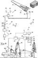
図19は、概略的に本発明の実施可能な実施形態を示している。前述した横引き用コンピュータは、符号8が付されている。収穫機1における全体としてのコンピュータ装置は、符号31で示されている。このコンピュータ装置は、横引き用コンピュータ8とは別体で、1つもしくは複数の前述したGPSユニット27、27’から収穫機の実際の位置に対応した位置情報を得るために設けられたコンピュータ32からなる。符号28は、収穫機の運転者の前方に位置する森林の一部分ずつの距離を決定し、スキャンする1つまたは複数のスキャナもしくは同様のものを示している。符号30は、前述した角度検出装置などを概略的に表わしている。
【0054】
収穫作業が進行するにつれて、横引き用コンピュータ8は、材木に関する品質と大きさを記録する。さらなるコンピュータ32は、装置27〜30から受信した情報によって収穫装置の位置を決定する。次に、コンピュータ32は、マーキング装置9によって前述した好ましくはコード形式におけるマークを材木の上に付与する。このコードは、コンピュータ32によって材木の性質を表わすデータに関係づけられ、横引きコンピュータ8によって確立される。これらのデータは、コンピュータ32によって保存される。
【0055】
GPSユニット27、27’は、位置を決定することに必要な信号と付加的な信号を衛星33もしくはそのようなものから受信する。
【0056】
コンピュータ32は、可能であれば横引き用コンピュータ8も、アンテナ34aと接続された送/受信機34を介して、送/受信機35と無線交信するようになっている。送/受信機35は、アンテナ36を有し、第2コンピュータ装置37のベースコンピュータ38と接続されている。このように、データは、無線により収穫機のコンピュータ32からベースコンピュータ38に転送可能である。ベースコンピュータ38に入力されたデータは、1つもしくは複数の第2コンピュータ装置37に組み込まれている1つもしくは複数のデータベースに記憶保存される。そのように第2コンピュータ装置37は、その地域の適切な数だけ配備されることが好ましい。図5において前述した制御センター17は、ベースコンピュータ38と接続されているように示されている。このように、制御センター17は、ベースコンピュータから評価と制御のために必要とされるデータを受け取ることができる。符号39は、例えば、ベースコンピュータ38に森林地図や収穫計画などを供給するユニットである森林収穫計画ユニットを示す。次に、これらの森林地図や収穫計画などは、無線によって収穫機に伝送され、収穫機の運転者を例えば、表示装置40を介して案内することに、もしくは受信されたデータに基づいて自動的に収穫機を制御すること使用される。このように、これらのデータは、案内により収穫機が自動的に該当する範囲内において移動され、収穫計画において収穫するように決定された木を収穫するように、非常に正確である必要がある。
【0057】
図19において、ベースコンピュータ38と収穫機のコンピュータ装置31とを通信することに使用される衛星41も示されている。
【0058】
図19は、また概略的に、前述した再生装置19、20を有する製材所42を示している。製材所42は、コンピュータ44を有する第3コンピュータ装置43を有する。これは、再生装置19、20から得られた情報を受信してこの情報をさらに、可能であれば無線45を介してベースコンピュータ38に転送する。次に、ベースコンピュータ38は、製材所42から製材所における材木とその性質についての情報を得て、ベースコンピュータ38に保存されているデータが、補足され個別に修正される。このことは、例えば、収穫計画と製材所において得られた実際の材木生産量とを比較することによって生産組織(production chain)内の弱いリンク(link)を特定できるということを意味する。製材所42内のコンピュータ44は、マーキング装置46および分類装置47と接続することが好ましい。製材所において産出された板材もしくは板材群は、マーキング装置46によって、板が産出された木の生育場所、品質および大きさなどの情報に関するデータと関連されたコード形式で、マークを付与されることが好ましい。コンピュータ44と接続されている前記分類装置47は、コンピュータ44によって制御されて、ある木もしくは木のある群から得られた板材が寄せ集められて梱包され、または他の木も集合板材とされ、この集合板材に並列した前述したコードでマークするために条件が与えられる。
【0059】
図19において示したシステムは、コンピュータ装置同士で連続的かつ自動的にデータ交換が可能である。前述したものを補足するものとして、収穫機に取り付けられたコンピュータ32は、収穫機によって切断された材木の場所に関する情報を記憶保存することができるということが指摘されなければならない。これにより、材木の運搬に関して通運業者は、コンピュータ32から無線を介して入手するかもしくはベースコンピュータ38からデータが既に送信済みであれば当該コンピュータ38から入手し、または直接通運業者を運搬するべき材木の場所に導く基礎を形成する。
【0060】
図19において示されているシステムは、制御センタ17から連続的な収穫に関する指示を可能にする。すなわち収穫作業がセンタから非常に遠く離れている場所で指示される。
【0061】
本発明は、前述した実施形態に限定されるものではないことは自明である。例えば、任意の検出技術、例えばビデオ測量法や他の映像技術などによって、収穫機に設けられた位置決定ユニットに対する収穫装置の位置を決定することが可能であることが指摘されなければならない。また、一般に多くの修正が、本発明にかかる基本的な考えにおいて当業者によって提案されることが指摘される。
【図面の簡単な説明】
【図1】 データを飛行機から取得し、高地図精度のデジタル地形モデルで風景を再生するのに利用する方法を示す図。
【図2】 森林立木を示す概略図で、aは森林の一部分の航空写真、bは森林の標準部分の正面図、cは上方から見た森林の一部を示す図である。
【図3】 森林に対する画策を促進するために純粋な風景データと森林の素材を組み合わせる方法を示す図。
【図4】 実際の作業場における森林収穫機を示す概略図。
【図5】 森林収穫組織をオペレーションセンタに接続する方法を示す概略図。
【図6】 本発明による方法を実施した結果として、材木の一片についての識別と出所を顧客への流れの中で追従させる方法を示す概略図。
【図7】 切断手段を備えた収穫装置の放出端を示す斜視図。
【図8】 本発明による一片の材木の一端にマークする方法を示す概略図。
【図9】 動作位置と非動作位置の間で移動可能なマーキング手段を備えたマーキング装置を示す概略図。
【図10】 パンチの特徴を有するマーキング手段の概略図。
【図11】 aとbは代案のマーキング装置を示す概略図。
【図12】 マーキング装置の代案を示す図。
【図13】 製材所と連結したクリーニング装置の斜視図。
【図14】 収穫機の車両の上の位置決定ユニットと、該位置決定ユニットに対する収穫装置の位置を決定する手段とからなる位置決定装置を備えた収穫機を示す概略図。
【図15】 図14に示すものの代案である解決手段の図。
【図16】 代案を示す図。
【図17】 さらなる代案を示す図。
【図18】 収穫機に配置されたスキャナーを収穫すべき木を走査するのに使用し、走査情報を制御ユニットにより利用し、クロスカットまたはクロスカットの予測を決定する方法を示す概略図。
【図19】 本発明の実際の適用において、データを登録し、非常に合理的な森林管理システムを達成するのに利用する方法を示す概略図。
【符号の説明】
1 収穫機
2 車両
3 収穫装置
5 位置決定装置
9 マーキング装置
10 材木片
13 マーキング手段
19,20 読取装置
27 位置決定ユニット
28 スキャナ
31 第1コンピュータ装置
37 第2コンピュータ装置
38 データベース
42 製材所
43 第3コンピュータ装置
46 マーキング装置[0001]
(Background of the Invention)
The present invention relates to a timber harvesting method and a forest management system.
[0002]
Conventional timber harvesting and related work is relatively primitive in the sense that timber material is handled as a bulk product. Even if standing trees are evaluated as a preparation for harvesting, they are rather crude. Therefore, the actual outcome of the harvest is quite different from the theoretically calculated outcome. A further problem with today's timber harvesting technology is that timber harvesting tends to occur on a relatively small scale in the sense that one seller and one buyer of timber are involved in the harvest. The boundaries between different forest owners must be carefully considered. This is a result of the fact that forest materials cannot be confirmed in detail. In addition, it is true that current harvester operators have fewer supporters when doing forest work. The harvester typically has a cross-cut computer that does not contact the tree during processing, except for contact between the harvester's harvesting arrangement and the tree. Therefore, there is no clear reason to improve the accuracy of the crosscut operation.
[0003]
Due to the aforementioned drawbacks, there is a considerable cost. A great deal of manual planning and management work is required.
[0004]
(Description of the invention)
The purpose of the present invention is primarily to create conditions for the rationalization of forest harvesting and its planning.
[0005]
According to a first aspect, the present invention aims to improve the possibility of correcting the harvest plan in a reasonable way, taking into account the actual results of the harvest.
[0006]
According to a second aspect, the present invention aims to create conditions for providing improved computer assistance for harvester operators. A fully automatic control of the harvester is primarily intended.
[0007]
According to a third aspect, the present invention aims to create conditions for handling timber material as a product whose origin is identified, not as a bulk product of unknown origin.
[0008]
According to a fourth aspect, the present invention creates a better follow-up of the harvesting plan by extracting information about the actual utilization of the timber pieces at the end of the processing chain of the timber pieces. It is aimed.
[0009]
According to a fifth aspect, the present invention aims to reduce problems associated with locating timber pieces processed by a harvester on the terrain. Such positioning is usually done by a carrier, but its job is to transport timber out of the forest.
[0010]
The first aspect of the present invention is that it is possible in highly developed remote registration and analysis techniques to create very detailed and accurate data on the characteristics of forest stands including the geographical and geological conditions of stands It is based on the reality that it is. This database may contain very precise and accurate regeneration of forest trees, but individual trees are to be determined in position with an accuracy of the order of a few centimeters to a few decimeters. . In addition, individual trees should be carefully evaluated for tree quality and content. As an example, the resolution of the database must be such that the forestry planner can click and rotate individual trees with a normal computer mouse and still achieve computer-based crosscut prediction I can say. In this regard, the present invention aims to create conditions for very accurate and rapid follow-up of harvest plans by feedback of real harvest data. This aspect of the invention is dealt with in claim 1.
[0011]
The second aspect of the present invention is achieved by what is mainly described in
[0012]
The third aspect of the present invention is achieved by what is described in
[0013]
That is, according to the present invention, in a method for harvesting forest timber by a harvester comprising a vehicle and a harvesting device mounted on the vehicle, the position of the harvester regarding tree cutting is determined, and at least one obtained from the tree. One solution is to mark the position information or its code on one piece of timber, thereby associating the piece of timber with the actual position information stored in the database.
[0014]
Thereby, the acquired timber piece becomes an individual connectable to the growth place. This means that individual forest owners can decide with certainty whether the timber pieces belong to themselves or others after transporting the timber pieces from the harvesting site.
[0015]
The conversion of timber material from bulk goods to identifiable individuals not only allows multiple sellers to keep the product at ease, but also allows multiple buyers to handle at the same harvest location. It means that you can do it. When the idea of the present invention is fully utilized, it is possible to describe from which tree the timber piece has flowed out accurately based on the position information marked on the timber piece. The analysis of standing trees performed before harvesting is accurately performed by the remote analysis technique described below. Individual trees may be unclearly determined in terms of position, but rather are predicted with high accuracy in terms of timber quality and volume. Such prior accurate analysis means that the yield of a certain harvest can be calculated very accurately in advance. Furthermore, the true harvest may be controlled very objectively. Thus, precisely, the harvested tree is actually harvested with optimal results. According to the present invention, the computer device arranged in the harvester controls the harvester based on the data flowing out from the preliminary analysis of the forest area and the harvest information determined based on the data, and harvests in advance. It is only possible to accurately harvest the tree so determined. Such a single tree level high resolution can be achieved if the correct registration of forests is done by photographic and other registration techniques and these registrations are precisely adjusted to the geographically correct state. Achieved. Furthermore, ultra-high resolution is required for position determination devices located on harvested trees. Such a high resolution can already be acquired by a satellite GPS system (global positioning system) today.
[0016]
According to a fourth aspect of the present invention, markings on individual pieces of wood that are sawed into a plate are read before sawing and this marking information is stored. Thereby, the board flowing out from the timber piece is provided with a marking including at least information on the growth position of the raw wood or its code. This associates the timber pieces with the growth location. Conditions are created for additional checks of harvest results for both volume and quality. Information about the actual yield of the board from the piece of timber can be correlated with identification information about the piece of timber at the sawmill. This makes it possible to obtain accurate conclusions regarding the yield of individual trees. Land owners are expected to increase the value of the forest as a result of the evaluation of forest stands, resulting in economic yields, incompetent cross-cuts and improper handling from other viewpoints. We get a substantially improved possibility of checking for a substantial drop.
[0017]
According to the fifth aspect of the present invention, the computer device determines and registers the position of the harvesting device when discharging the processed timber pieces from the harvesting device, and the position information is stored in the database or subsequently by the carrier. It is designed to be stored on a data carrier that is used when pulling out a piece. In this way, the timber pieces can be safely found in the area. In this regard, it is preferable to show the location information regarding the timber pieces to the driver of the carrier. Thereby, a carrier can be moved to a timber piece. According to one development, carrier movement is considered to occur completely automatically under computer control based on location information and pre-established standing tree plans.
[0018]
Even if the pre-analysis and harvesting are performed with an accuracy equivalent to the resolution of the order of the individual trees as described above, even though the optimal advantages of the present invention can be obtained, the idea of the present invention is to a lesser extent, for example 1 Or, when done with resolutions on the order of a few meters, smaller resolutions can be used.
[0019]
Particular features of the system according to the invention will be apparent from the claims.
[0020]
(Description of Embodiment of the Invention)
Details and advantages associated with the present invention are described in detail below.
[0021]
DETAILED DESCRIPTION OF THE INVENTION
In order to make full use of the advantages of the present invention, it is necessary to create a basis for making good decisions in forest management. On the one hand, high-quality and cost-effective explanation of soil (geology, 4th geology, natural geography, hydrology, climatology, soil science, cultivation biology, nutrient geology and various planning maps) The purpose is to ensure. In FIG. 1, a method for extracting data used to reproduce an accurate landscape map in a digital phase model is shown, particularly with different recording techniques from aircraft. Furthermore, it is necessary to accurately record forests that grow within the range in this landscape map. Different techniques for recording forests growing from aircraft, such as photogrammetry or photographic analysis techniques, are also preferably used here. An aerial photograph is shown in FIG. 2a, and each tree can be discriminated from the aerial photograph. With proper photographic analysis techniques and the nature of different types of trees and their knowledge of their habitat in different environments, it is possible to obtain a relatively accurate understanding of their material and volume for individual timbers. . By matching the actual map coordinates with what is actually reproduced by an exact reproduction technique, individual trees can be determined with respect to position with very high accuracy, centimeter order or at least 10 centimeter order accuracy It is. In FIG. 2c, the individual trees are shown tilted outward from the center of the photograph in the central projection with respect to the reproduction technique so that the individual trees can be distinguished. Good evaluation of growing forest timber is possible by considering shade effects, tree silhouette cones, leaf size and amount of needles, their color, and so on. This assessment is the basis for a very careful and accurate decision regarding harvest planning.
[0022]
In FIG. 3, it is shown that the landscape map and the forest log data are synthesized in the cross-sectional regeneration that facilitates the harvesting plan.
[0023]
In FIG. 4, it is shown that the harvesting machine 1 denoted by reference numeral 1 includes a
[0024]
The GPS satellite is indicated by
[0025]
The harvesting machine 1 is provided with a marking device. This device is shown as one embodiment in FIG. The marking
[0026]
However, given the location information about the timber growing location as a timber piece marking and reading the marking, the tree can be associated with the growing location without any other data that has to be extracted from the database, It is shown to be within the scope of the present invention. In the case where not all the trunks are handled, it is necessary to supplement the position information about the growing place with the number related to the place of the corresponding lumber piece in the tree. The timber pieces may also be provided with information that can be read into the timber, such as information about quality, size, and the like. Especially when a large amount of information needs to be combined with a piece of timber, but usually the piece of timber is matched with one code, instead the data is stored in one or more databases, and the associated data is code Is preferably associated with a piece of timber. In this regard, the further data by the code means that can be related to the piece of wood is preferably information about the actual buyer and possibly the seller.
[0027]
Seller information is not necessarily required if it is possible to associate forest habitats with sellers. As shown in FIG. 7, the discharge end of the harvesting device 3 is shown, and the end of the timber is discharged by the feeding means 11 of the device 3. The device has a cutting means 12 for cutting the supplied piece of timber at the location of this discharge end. In this embodiment, the cutting means 12 is a chainsaw having a chain that is rotatably provided and travels. Other cutting means are also possible. The marking device according to the invention is preferably provided at the discharge end of the harvesting device, whereby according to this embodiment, the supplied timber pieces are marked immediately after being cut off from the rest of the log be able to. Furthermore, the marking can also be performed on the ends of the timber pieces to be cut off, but this requires rather high speed. However, other embodiments are fully possible. In this way, the marking device may apply the marking on the surface of the outer surface of the timber piece after releasing a part of the surface of the outer surface from the bark if possible. According to another embodiment, it is also possible to mark a piece of wood that is not separated from the rest of the log. However, this means that a prediction about the quality and volume of the timber must then be made. If the prediction is incorrect, an error can occur.
[0028]
A possibility for carrying out the marking on the timber pieces is to integrate the marking device and the cutting means 12 by providing the cutting means 12 with marking means suitable for the purpose. These may be non-contact type or contact type. According to a possible embodiment, the marking means has the characteristics of a spray nozzle suitable for spraying marks that contain information as described above on already cut timber. The condition for this is a relatively large number of spray nozzles. In principle, a mark having a large amount of information content can be given to the entire end face of the timber. More limited information content is also particularly possible when only code is used.
[0029]
In FIG. 8, a
[0030]
In FIG. 9, a marking
[0031]
FIG. 5 shows that each harvested tissue is connected to the control center 17 and can communicate with other units in the harvested tissue via telephone or radio waves. The harvester is indicated by reference numeral 1. Information about the forest to be harvested is transmitted from the computer 8 of the harvester 1 to the control center 17 to control the harvesting operation of the harvester 1 so that the harvest is concentrated, for example, in the assortment that is required for the time being. A signal suitable for this is transmitted from the control center 17 to the harvester 1. The control center 17 is also in communication with other units such as means of transportation within the harvesting tissue and timber consumers such as sawmill or pulp industry. Preferably, the control center 17 continues to effectively record the position of the harvesting tissue unit via the GPS system and effectively plans the harvesting operation. It is preferred that the control center 17 always have data that allows to know the available timber, the location of the timber available by harvesting, and the expected quality and quantity of each, so that the negotiations will control the control center. It is established very quickly using it. In other words, the control center can function as an “electronic” timber transaction.
[0032]
In FIG. 6, it is shown how the
[0033]
The reproducing
[0034]
The mark on the
[0035]
FIG. 10 shows the structure of the marking
[0036]
The cam-shaped projecting
[0037]
It is also possible to combine the punching
[0038]
In FIG. 11, a
[0039]
As shown in FIG. 12, the
[0040]
Other marking techniques are naturally possible. One useful marking technique is based on the use of laser jet means to apply the desired mark on the log, for example in the form of a bar code or otherwise. Many laser marking means can be arranged in a matrix shape in the manner described above for the structural embodiment. In addition to laser technology, other radiant energy can of course be used as a means of marking.
[0041]
It is also possible to design the marking device to apply the required marking information on a separate carrier and then apply the carrier onto the timber. This can be, for example, an elongated piece of marking information provided in a bar code format or other code.
[0042]
In FIG. 13, one cleaning device provided at the intake of the sawmill is shown. This cleaning device removes contaminants that make marking information such as snow and ice more difficult to read from timber. The cleaning device preferably has, for example, a steam shower property. If the marking information is attached only to the end of the timber unit, it is sufficient for the cleaning device to perform the cleaning operation at the end.
[0043]
It should be noted that the reading device as indicated by
[0044]
FIG. 14 shows a harvester equipped with the
[0045]
In FIG. 14, the means for determining the position of the harvesting device 3 with respect to the
[0046]
FIG. 15 shows a slightly different harvester. The vehicle in this figure also has a
[0047]
As shown in FIG. 16, as an alternative, the
[0048]
The fact that there are two positioning units in the harvester and appropriately connected with the computer 8 that can evaluate the signal from the unit for positioning means that the direction of the crane is always It means that it can be determined even when the crane is in operation. This embodiment has a
[0049]
The alternative shown in FIG. 17 has a
[0050]
Schematically in FIG. 18, the
[0051]
The prediction of the transverse pull determined by the
[0052]
It should be emphasized that the application of the present invention is not limited to the type of harvester in the illustrated embodiment. Therefore, the present invention can also be applied to a harvester having a crane provided with only one what is generally called a felling head. The device cuts the wood, which is then laid down by a crane into a processing machine provided on the vehicle chassis. Usually, the processor has both a pruning means and a cutting means. In such a machine, the ferring head is considered equivalent to the harvester in the previous embodiment in the sense that what is determined to determine the position of the tree is the position of the ferring head in the region. Should. In other words, whether the additional processing device can be combined with the fallen tree part, that is, whether it is provided on the crane, or instead provided on the chassis of the vehicle, and the log is carried into the processing part by the crane is the idea of the present invention. Is completely out of order.
[0053]
FIG. 19 schematically illustrates a possible embodiment of the present invention. The above-described horizontal pulling computer is denoted by reference numeral 8. The computer device as a whole in the harvester 1 is indicated by
[0054]
As the harvesting operation proceeds, the horizontal drawing computer 8 records the quality and size of the timber. The
[0055]
The
[0056]
If possible, the
[0057]
Also shown in FIG. 19 is a
[0058]
FIG. 19 also schematically shows a
[0059]
The system shown in FIG. 19 can exchange data continuously and automatically between computer devices. In addition to the foregoing, it should be pointed out that the
[0060]
The system shown in FIG. 19 allows instructions regarding continuous harvesting from the control center 17. That is, the harvesting operation is directed at a place that is very far from the center.
[0061]
It is obvious that the present invention is not limited to the embodiment described above. It should be pointed out that it is possible to determine the position of the harvesting device relative to the positioning unit provided in the harvester, for example by any detection technique, such as video surveying or other imaging techniques. It is also pointed out that many modifications are generally proposed by those skilled in the art in the basic idea of the invention.
[Brief description of the drawings]
FIG. 1 is a diagram showing a method of acquiring data from an airplane and using it to reproduce a landscape with a digital terrain model with high map accuracy.
FIG. 2 is a schematic diagram showing forest stands, where a is an aerial photograph of a part of the forest, b is a front view of a standard part of the forest, and c is a part of the forest viewed from above.
FIG. 3 is a diagram illustrating a method of combining pure landscape data and forest materials to promote forest planning.
FIG. 4 is a schematic diagram showing a forest harvester in an actual work place.
FIG. 5 is a schematic diagram illustrating a method for connecting a forest harvesting organization to an operations center.
FIG. 6 is a schematic diagram showing how to identify and source a piece of timber in the flow to a customer as a result of performing the method according to the present invention.
FIG. 7 is a perspective view showing a discharge end of a harvesting device provided with cutting means.
FIG. 8 is a schematic diagram illustrating a method of marking one end of a piece of timber according to the present invention.
FIG. 9 is a schematic view showing a marking device provided with marking means movable between an operating position and a non-operating position.
FIG. 10 is a schematic view of a marking means having a punch feature.
FIGS. 11A and 11B are schematic views showing an alternative marking device. FIGS.
FIG. 12 is a diagram showing an alternative marking device.
FIG. 13 is a perspective view of a cleaning device connected to a sawmill.
FIG. 14 is a schematic diagram showing a harvester equipped with a position determining device comprising a position determining unit on a vehicle of the harvester and means for determining the position of the harvesting device with respect to the position determining unit.
FIG. 15 is a diagram of solution means that is an alternative to that shown in FIG. 14;
FIG. 16 is a diagram showing an alternative.
FIG. 17 shows a further alternative.
FIG. 18 is a schematic diagram illustrating a method of using a scanner located in a harvester to scan a tree to be harvested and utilizing the scanning information by a control unit to determine crosscuts or crosscut predictions.
FIG. 19 is a schematic diagram illustrating a method used to register data and achieve a very reasonable forest management system in an actual application of the present invention.
[Explanation of symbols]
1 Harvester
2 Vehicle
3 Harvesting equipment
5 Positioning device
9 Marking device
10 Timber pieces
13 Marking means
19, 20 Reader
27 Positioning unit
28 Scanner
31. First computer device
37 Second computer device
38 database
42 Sawmill
43. Third computer device
46 Marking equipment
Claims (19)
無線により受信可能な外部信号により収穫機の位置を決定することができる収穫機に配置された少なくとも1つの位置決定装置(5)により、木の伐採に関する収穫機の位置を決定し、
マーキング装置(10,9)により、当該木から得られる少なくとも1つの材木片に位置情報またはそのコードをマークし、
これにより、材木片を位置情報と関連させ、
位置情報またはそのコードを当該材木片に関する品質またはサイズと関連させるのに使用することを特徴とする材木収穫方法。A vehicle (2), a harvesting device (3) mounted on the vehicle, a computer device (31) provided in the vehicle for registering the quality or size of the harvested timber pieces, and a timber piece obtained from a tree In a method for harvesting forest timber by a harvesting machine comprising a marking device (9) provided on a vehicle to give a marking (13) to (10),
Determining the position of the harvester with respect to tree cutting by means of at least one position determining device (5) arranged in the harvester, which can determine the position of the harvester by means of an externally receivable external signal;
Marking position information or its code on at least one piece of timber obtained from the tree by means of the marking device (10, 9),
This associates the timber pieces with the location information,
A method for harvesting timber, characterized in that it is used for associating position information or its code with the quality or size of the timber piece.
収穫機の位置を決定するために、外部の無線で受信可能な信号によって収穫機の位置を決定することができる少なくとも1つの位置決定装置(5)を収穫機に配置し、
前記コンピュータ装置(31)はマーキング装置(9)を制御して材木片に位置情報またはそのコードをマークするように配置され、
これにより、位置決定装置(5)から受信した位置情報に基づいて、材木をデータベースに記憶された位置情報と関連させるようにしたことを特徴とする森林管理システム。The vehicle (2), the harvesting device (3) mounted on the vehicle, and the harvester (1) arranged to give a mark (13) to at least one piece of wood (10) obtained from the tree In a forest management system including timber harvesting by a harvester (1) comprising a marking device (9) and a computer device (31) arranged in the harvester to control the marking device to mark timber pieces,
In order to determine the position of the harvester, at least one position-determining device (5) that can determine the position of the harvester by means of an externally receivable signal is arranged in the harvester,
The computer device (31) is arranged to control the marking device (9) to mark the position information or its code on the timber piece,
Thereby, based on the positional information received from the position determination apparatus (5), the timber is related to the positional information stored in the database.
前記コンピュータ装置(31)は、マーキング装置を制御して材木片に品質またはサイズの情報をマークし、この情報を前記コードによって材木片と関連可能なように登録するようになっていることを特徴とする請求項8に記載のシステム。The harvester comprises means for determining and inputting information relating to the quality or size of the timber pieces;
The computer device (31) controls the marking device to mark the timber pieces with quality or size information and registers the information so as to be associated with the timber pieces by the code. The system according to claim 8.
前記コンピュータ装置は、マーキング装置を制御して、材木片に位置情報をマークし、またはこの位置情報を前記コードによって材木片と関連可能なように登録するようになっていることを特徴とする請求項8または9のいずれかに記載のシステム。The harvester comprises means for automatically determining or manually entering information relating to the current timber position in the material;
The computer device controls a marking device to mark position information on a piece of wood or register the position information so as to be associated with the piece of wood by the code. Item 10. The system according to any one of Items 8 and 9.
マーキング装置を制御して、材木片に買手または売手に関する情報をマークし、またはこの情報を前記コードによって材木片と関連可能なように登録するようになっていることを特徴とする請求項8から10のいずれかに記載のシステム。Said computer device comprises means for accepting information about a buyer or seller of individual timber pieces;
9. The marking device is controlled to mark information relating to a buyer or a seller on a piece of wood or to register this information so as to be associated with the piece of wood by means of the code. The system according to any one of 10.
当該位置情報は、データベースに記憶して、その後の運送業者による材木片の引出し(fetching)で使用されるようになっている請求項8から11のいずれかに記載のシステム。The computer device is adapted to determine and register the position of the harvesting device when discharging the processed timber pieces from the harvesting device;
12. A system according to any one of claims 8 to 11, wherein the location information is stored in a database and is used for subsequent fetching of timber by a carrier.
該位置決定ユニットに対する収穫装置の位置を決定する手段が収穫機に設けられていることを特徴とする請求項8から18のいずれかに記載のシステム。The harvester positioning device (5) comprises at least one positioning unit (27) in the harvester vehicle;
19. A system according to any of claims 8 to 18, wherein means for determining the position of the harvesting device relative to the position determining unit is provided in the harvester.
Applications Claiming Priority (4)
| Application Number | Priority Date | Filing Date | Title |
|---|---|---|---|
| SE9603880A SE9603880D0 (en) | 1996-10-23 | 1996-10-23 | Forest planning and process |
| PCT/SE1997/001782 WO1998017099A1 (en) | 1996-10-23 | 1997-10-23 | Method for timber harvesting and system for forestry |
| WO9701782 | 1997-10-23 | ||
| PCT/SE1998/000788 WO1999023873A1 (en) | 1996-10-23 | 1998-04-28 | Method for timber harvesting and system for forestry |
Publications (2)
| Publication Number | Publication Date |
|---|---|
| JP2001522591A JP2001522591A (en) | 2001-11-20 |
| JP4580100B2 true JP4580100B2 (en) | 2010-11-10 |
Family
ID=20404350
Family Applications (1)
| Application Number | Title | Priority Date | Filing Date |
|---|---|---|---|
| JP2000519989A Expired - Fee Related JP4580100B2 (en) | 1996-10-23 | 1998-04-28 | Timber harvesting method and forest management system |
Country Status (22)
| Country | Link |
|---|---|
| US (2) | US6182725B1 (en) |
| EP (2) | EP0957674B1 (en) |
| JP (1) | JP4580100B2 (en) |
| CN (1) | CN1317941C (en) |
| AT (2) | ATE230559T1 (en) |
| AU (2) | AU727698B2 (en) |
| BR (1) | BR9814101A (en) |
| CA (2) | CA2269732C (en) |
| DE (2) | DE69718349T2 (en) |
| DK (1) | DK1024688T3 (en) |
| EA (1) | EA002229B1 (en) |
| EE (1) | EE04255B1 (en) |
| HU (1) | HUP0004041A3 (en) |
| ID (1) | ID25496A (en) |
| NO (2) | NO315921B1 (en) |
| NZ (2) | NZ335923A (en) |
| RU (1) | RU2208307C2 (en) |
| SE (1) | SE9603880D0 (en) |
| SK (1) | SK287210B6 (en) |
| TR (1) | TR200001914T2 (en) |
| UA (1) | UA59421C2 (en) |
| WO (2) | WO1998017099A1 (en) |
Families Citing this family (99)
| Publication number | Priority date | Publication date | Assignee | Title |
|---|---|---|---|---|
| SE9603880D0 (en) * | 1996-10-23 | 1996-10-23 | Bengt Soervik | Forest planning and process |
| CA2287033A1 (en) * | 1999-10-21 | 2001-04-21 | Geoid Exploration Ltd. | Land-marking device and a method of land surveying and marking |
| ID28584A (en) * | 1999-12-03 | 2001-06-07 | Green Earth Ltd | METHOD OF FINDING WOOD IN FOREST AND MACHINE TO RUN THE METHOD |
| EP1127666B1 (en) * | 2000-02-23 | 2004-07-21 | Meinan Machinery Works, Inc. | Apparatus for detecting markings on opposite end faces of a wood block |
| SE520298C2 (en) * | 2000-08-15 | 2003-06-24 | Bengt Soervik | Process and aggregates for logging of forest and forest management systems |
| SE520299C2 (en) * | 2000-08-23 | 2003-06-24 | Bengt Soervik | Process and system for handling pieces of wood |
| DE10123045A1 (en) * | 2001-05-11 | 2002-11-21 | Tenovis Gmbh & Co Kg | Method for entering a phone number in a telecommunication device and telecommunication device |
| SE0102772D0 (en) * | 2001-08-21 | 2001-08-21 | Fiberpac Ab | Forestry |
| SE522906C2 (en) | 2001-09-28 | 2004-03-16 | Telenvironment Ab | Procedures and systems for controlling the quality and origin of meat products |
| CA2368523A1 (en) * | 2002-01-18 | 2003-07-18 | Genus Resource Management Technologies Inc. | Method and system for integrated natural resource management |
| US20040143463A1 (en) * | 2002-04-26 | 2004-07-22 | Murcia Philippe R. | Clean forest region certification |
| US6888458B2 (en) | 2002-05-21 | 2005-05-03 | Weyerhaeuser Company | Methods for tracking silvicultural information |
| ES2447418T3 (en) * | 2002-08-27 | 2014-03-12 | Dralle A/S | Procedure and automatic measurement and tracking system for logs, industrial wood and planks |
| US7100817B2 (en) * | 2002-09-09 | 2006-09-05 | B. R. Close | System and method of forestry management using radio frequency identification tags |
| US20040250908A1 (en) * | 2002-12-19 | 2004-12-16 | Hicks Keith B. | Method and system configured to manage a tree harvesting process |
| US20060266817A1 (en) * | 2003-08-26 | 2006-11-30 | Brad Close | System and method of forestry management using radio frequency identification tags |
| US7320349B2 (en) * | 2003-12-18 | 2008-01-22 | Caterpillar Inc. | Tree harvester |
| CA2526292C (en) * | 2004-11-09 | 2013-03-12 | Lyle Baker | Integrated mill |
| ITMI20051925A1 (en) * | 2005-10-12 | 2007-04-13 | Metapontum Agrobios S R L | METHOD FOR TRACKING OF PLANTS |
| US20080015711A1 (en) * | 2006-06-27 | 2008-01-17 | Normand Charland | Systems and methods for forest harvest management |
| FI119962B (en) * | 2006-08-31 | 2009-05-29 | Ponsse Oyj | Method and arrangement for measuring a piece of wood in a woodworking machine |
| US20080147519A1 (en) * | 2006-12-15 | 2008-06-19 | Scott Reigel | Method and System for Conducting Inventories and Appraisals |
| US20090076741A1 (en) * | 2007-09-19 | 2009-03-19 | Eb Associates, Inc. | Distributed system for measuring lumber in a sawmill |
| SE532295C2 (en) * | 2008-04-30 | 2009-12-01 | Marie Soervik | Harvester assembly for logging |
| US9235334B2 (en) | 2008-05-09 | 2016-01-12 | Genesis Industries, Llc | Managing landbases and machine operations performed thereon |
| SE532659C2 (en) * | 2008-06-11 | 2010-03-16 | Marie Soervik | Marking device and harvesting unit |
| US20090327104A1 (en) * | 2008-06-25 | 2009-12-31 | Sanders Craig C | System for tracking and providing visibility of origin of food elements |
| BRPI1011584A2 (en) * | 2009-06-29 | 2016-03-22 | Genesis Ind Llc | method and system for monitoring productivity associated with a machine |
| DE102009051960A1 (en) * | 2009-11-04 | 2011-05-05 | Eifelwerk Heinrich Stein Gmbh & Co Kg | Harvesting system for harvested crop e.g. bamboo, has storage position determination device sends storage position data to navigation system that determines storage route from storage position data, where route leads to storage place |
| FI20090447A (en) | 2009-11-26 | 2011-05-27 | Ponsse Oyj | Method and device in connection with a forestry machine |
| WO2011087405A1 (en) * | 2010-01-12 | 2011-07-21 | SÖRVIK, Marie | Marking device and harvesting arrangement for tree harvesting |
| FI123208B (en) * | 2010-05-20 | 2012-12-31 | Upm Kymmene Corp | Method and information system for determining the harvestability and transportability of a stand |
| SE534916C2 (en) * | 2010-06-18 | 2012-02-14 | Bengt Soervik | Marking device and harvester assembly |
| RU2468573C2 (en) * | 2010-11-18 | 2012-12-10 | Лев Николаевич Шобанов | Method to aim actuator of forest machine manipulator |
| ITMI20110423A1 (en) * | 2011-03-16 | 2012-09-17 | Giancarlo Spezia | PROCEDURE AND DEVICE FOR MARKING OF ARBOREE AND SIMILAR CULTIVATIONS |
| US8531300B2 (en) * | 2011-06-16 | 2013-09-10 | Cnh America Llc | System and method for tracking a cotton module |
| RU2478281C2 (en) * | 2011-07-01 | 2013-04-10 | Федеральное государственное образовательное учреждение высшего профессионального образования Дальневосточный государственный аграрный университет | Self-propelled belt sawmill |
| US9147014B2 (en) | 2011-08-31 | 2015-09-29 | Woodtech Measurement Solutions | System and method for image selection of bundled objects |
| CN102506707B (en) * | 2011-10-18 | 2013-12-25 | 北京华力兴科技发展有限责任公司 | Volume analysis method |
| ES2486305T3 (en) | 2011-10-21 | 2014-08-18 | Siemens Aktiengesellschaft | Procedure and device to locate a collection point of an object in an installation |
| US20130269537A1 (en) | 2012-04-16 | 2013-10-17 | Eugenio Minvielle | Conditioning system for nutritional substances |
| US8490862B1 (en) | 2012-04-16 | 2013-07-23 | Eugenio Minvielle | Transformation system for nutritional substances |
| US20130269538A1 (en) | 2012-04-16 | 2013-10-17 | Eugenio Minvielle | Transformation system for nutritional substances |
| US9541536B2 (en) | 2012-04-16 | 2017-01-10 | Eugenio Minvielle | Preservation system for nutritional substances |
| US10219531B2 (en) | 2012-04-16 | 2019-03-05 | Iceberg Luxembourg S.A.R.L. | Preservation system for nutritional substances |
| DE102012007340B4 (en) * | 2012-04-13 | 2014-10-09 | Jörg Föller | Harvesting arrangement and method for harvesting wood |
| US9072317B2 (en) | 2012-04-16 | 2015-07-07 | Eugenio Minvielle | Transformation system for nutritional substances |
| US9414623B2 (en) | 2012-04-16 | 2016-08-16 | Eugenio Minvielle | Transformation and dynamic identification system for nutritional substances |
| US9121840B2 (en) | 2012-04-16 | 2015-09-01 | Eugenio Minvielle | Logistic transport system for nutritional substances |
| US20140069838A1 (en) | 2012-04-16 | 2014-03-13 | Eugenio Minvielle | Nutritional Substance Label System For Adaptive Conditioning |
| US9702858B1 (en) | 2012-04-16 | 2017-07-11 | Iceberg Luxembourg S.A.R.L. | Dynamic recipe control |
| US8550365B1 (en) | 2012-04-16 | 2013-10-08 | Eugenio Minvielle | System for managing the nutritional content for nutritional substances |
| US9564064B2 (en) | 2012-04-16 | 2017-02-07 | Eugenio Minvielle | Conditioner with weight sensors for nutritional substances |
| US9460633B2 (en) | 2012-04-16 | 2016-10-04 | Eugenio Minvielle | Conditioner with sensors for nutritional substances |
| US9016193B2 (en) | 2012-04-16 | 2015-04-28 | Eugenio Minvielle | Logistic transport system for nutritional substances |
| US9069340B2 (en) | 2012-04-16 | 2015-06-30 | Eugenio Minvielle | Multi-conditioner control for conditioning nutritional substances |
| US9528972B2 (en) | 2012-04-16 | 2016-12-27 | Eugenio Minvielle | Dynamic recipe control |
| US9429920B2 (en) | 2012-04-16 | 2016-08-30 | Eugenio Minvielle | Instructions for conditioning nutritional substances |
| US9171061B2 (en) | 2012-04-16 | 2015-10-27 | Eugenio Minvielle | Local storage and conditioning systems for nutritional substances |
| US9436170B2 (en) | 2012-04-16 | 2016-09-06 | Eugenio Minvielle | Appliances with weight sensors for nutritional substances |
| US8851365B2 (en) | 2012-04-16 | 2014-10-07 | Eugenio Minvielle | Adaptive storage and conditioning systems for nutritional substances |
| US9080997B2 (en) | 2012-04-16 | 2015-07-14 | Eugenio Minvielle | Local storage and conditioning systems for nutritional substances |
| US8733631B2 (en) | 2012-04-16 | 2014-05-27 | Eugenio Minvielle | Local storage and conditioning systems for nutritional substances |
| RU2496303C1 (en) * | 2012-05-03 | 2013-10-27 | Лев Николаевич Шобанов | Method of machine control |
| US9117185B2 (en) * | 2012-09-19 | 2015-08-25 | The Boeing Company | Forestry management system |
| AU2013203666B2 (en) * | 2012-10-10 | 2015-05-28 | Waratah Nz Limited | Method, apparatus, and system for controlling a timber-working device |
| FI20135625L (en) * | 2013-06-05 | 2014-12-22 | Ponsse Oyj | Method and arrangement for measuring a piece of wood |
| RU2533022C1 (en) * | 2013-06-11 | 2014-11-20 | Федеральное государственное бюджетное образовательное учреждение высшего профессионального образования "Воронежская государственная лесотехническая академия" | Method for determining growing stock |
| US10790062B2 (en) | 2013-10-08 | 2020-09-29 | Eugenio Minvielle | System for tracking and optimizing health indices |
| CN103552452A (en) * | 2013-11-08 | 2014-02-05 | 桂林福冈新材料有限公司 | Multifunctional united felling machine |
| RU2556070C1 (en) * | 2013-12-24 | 2015-07-10 | Федеральное государственное бюджетное образовательное учреждение высшего профессионального образования "Поволжский государственный технологический университет" | Method of automated decision-making on purpose of trees for cutting in their processing with timber harvesting machine |
| USD762081S1 (en) | 2014-07-29 | 2016-07-26 | Eugenio Minvielle | Device for food preservation and preparation |
| CN104122836B (en) * | 2014-08-13 | 2017-01-11 | 北京林业大学 | Semi-physical simulation system for operation track planning and control of forestry felling and cultivation machine |
| WO2016099723A2 (en) * | 2014-11-12 | 2016-06-23 | SlantRange, Inc. | Systems and methods for aggregating and facilitating the display of spatially variable geographic data acquired by airborne vehicles |
| CN104620935A (en) * | 2015-01-26 | 2015-05-20 | 甘肃省林业科学研究院 | Taproot cutting and logging method |
| CN104782445B (en) * | 2015-02-13 | 2017-03-22 | 李建尧 | Forestry felling saw device provided with alarm device and guided by guide groove and using method thereof |
| US9877437B2 (en) * | 2015-09-30 | 2018-01-30 | Deere & Company | Felled tree lean control system and method |
| CN109475091B (en) * | 2016-07-15 | 2022-05-13 | 松本良三 | Forestry harvester |
| EP3296467B1 (en) * | 2016-09-20 | 2018-12-12 | BAUER Spezialtiefbau GmbH | Excavation equipment and method |
| CN106358983B (en) * | 2016-10-08 | 2019-06-28 | 安徽理工大学 | A kind of the Premixed Abrasive Water Jet equipment on the tree grafting growth of mountain area |
| JP2018062069A (en) * | 2016-10-11 | 2018-04-19 | 尾州木材工業株式会社 | Timber management method |
| SE543160C2 (en) * | 2017-01-16 | 2020-10-13 | Tracy Of Sweden Ab | A method for determining and managing origin identifation of logs |
| RU2663280C1 (en) * | 2017-06-20 | 2018-08-03 | Федеральное государственное автономное образовательное учреждение высшего образования "Северный (Арктический) федеральный университет имени М.В. Ломоносова" | Method of cutting areas removal |
| EP3424302B1 (en) * | 2017-07-04 | 2023-08-30 | Andreas Stihl AG & Co. KG | Method for determining an orientation of at least one section of a felled tree and forest system for determining the orientation of at least one section of a felled tree |
| EP3424305B1 (en) | 2017-07-04 | 2021-05-26 | Andreas Stihl AG & Co. KG | Method of assisting the felling of a tree and system for assisting the felling of a tree |
| SE542511C2 (en) * | 2017-07-07 | 2020-05-26 | Soervik Bengt | Method for handling logs and log marking tool for use in such a method |
| EP3488686A1 (en) * | 2017-11-22 | 2019-05-29 | Deere & Company | Forestry machinery operation method and operation processor performing this method |
| CN108633533A (en) * | 2018-04-11 | 2018-10-12 | 北京木业邦科技有限公司 | The automatic Tending methods of trees, device, electronic equipment and storage medium |
| US10785913B2 (en) * | 2018-04-30 | 2020-09-29 | Orchard-Rite Ltd., Inc. | Two-piece harvester having a shaker and a receiver for harvesting tree fruits or nuts |
| AT520253A3 (en) * | 2018-07-16 | 2019-04-15 | Umweltdata G M B H | Selective harvesting method |
| CN109726937B (en) * | 2019-01-25 | 2022-05-10 | 福州大学 | Land use planning adjustment data quality degradation evaluation method based on shape measure |
| JP7135975B2 (en) * | 2019-03-28 | 2022-09-13 | トヨタ自動車株式会社 | Harvesting systems and methods |
| SE1950817A1 (en) * | 2019-06-28 | 2020-11-24 | Deep Forestry Ab | A method for preparing for harvesting of forest using an un-manned vehicle and un-manned vehicle and system using said method |
| US11785900B2 (en) * | 2019-09-04 | 2023-10-17 | Timberpro, Inc. | Forestry machine |
| CN110956096B (en) * | 2019-11-13 | 2024-02-23 | 北京农业智能装备技术研究中心 | Forestry infection epidemic wood removal management method and system |
| JP7218941B2 (en) * | 2020-08-07 | 2023-02-07 | 株式会社藤興業 | Virtual space formation method in felling direction of thinned wood |
| RU2752365C1 (en) * | 2020-11-19 | 2021-07-26 | Федеральное государственное бюджетное образовательное учреждение высшего образования "Поволжский государственный технологический университет" | Method for selective felling and care felling in plantings with two-row placement of forest crops |
| AT525540B1 (en) * | 2022-06-03 | 2023-05-15 | Beetle Fortech Gmbh | marking device |
| CN117237824B (en) * | 2023-11-14 | 2024-02-02 | 吉林省林业科学研究院(吉林省林业生物防治中心站) | Forest region harvesting detection equipment based on remote sensing image technology |
Family Cites Families (19)
| Publication number | Priority date | Publication date | Assignee | Title |
|---|---|---|---|---|
| US3787700A (en) | 1971-07-27 | 1974-01-22 | Atmospheric Sciences Inc | Automatic system for measuring selected dimensions |
| FI71013C (en) * | 1983-01-06 | 1986-10-27 | Schauman Wilh Oy | OVER ANCHORING FOER BESTAEMMANDE AV EN OENSKAD CENTRALLINJE FOER CYLINDERLIKA KROPPAR SAOSOM TRAESTOCKAR |
| ATE35870T1 (en) | 1985-05-15 | 1988-08-15 | Kajetan Latschbacher | PORTABLE DATA COLLECTION DEVICE. |
| SE454727C (en) * | 1986-09-30 | 1998-11-20 | Hans Dutina Research & Develop | Procedure for determining primarily the shape and/or position of elongated pieces of wood and device for performing the procedure |
| SE8702957L (en) | 1987-07-24 | 1989-01-25 | Oesa Ab | PROCEDURE FOR HANDLING AND TRANSPORTATION OF STOCK FROM CUTTING PLDTS TO CUSTOMER JAEMTE LANDWEGS VEHICLES BEFORE IMPLEMENTATION OF THE PROCEDURE |
| GB2211103A (en) * | 1987-12-18 | 1989-06-28 | Flaxman Binns Frances Julia | Toy or games equipment |
| US4947909A (en) * | 1989-02-14 | 1990-08-14 | Cae Machinery Ltd. | Process and apparatus for optimizing volume of boards cut from a log |
| JPH02257280A (en) * | 1989-03-30 | 1990-10-18 | Sumitomo Ringyo Kk | Forest data control system |
| FI86949C (en) | 1990-02-23 | 1992-11-10 | E P Elektroniikka Oy | Procedure for marking wooden pieces |
| CA2079517A1 (en) | 1991-10-01 | 1993-04-02 | Michael C. Ryan | Method for identifying a penetrable member |
| DE4134790A1 (en) * | 1991-10-22 | 1993-04-29 | Dietrich Gerhard Ellsaesser | Autonomous forestry system delivering small dia. tree trunks - combines micro-orientation system involving marked trees and macro-orientation system using GPS for navigation of small tracked vehicle |
| DE4232412A1 (en) * | 1992-09-28 | 1994-03-31 | Dietrich Gerhard Ellsaeser | Forestry integrated data acquisition system - contains manual control unit mounted on clothing for input of data from electronic tape measure or laser distance meter and coupled to computer and/or storage unit by wireless radio link |
| NZ245399A (en) * | 1993-01-14 | 1995-05-26 | Interpine Export Nz Ltd | Portable computerised log measurer |
| JP3179254B2 (en) * | 1993-08-03 | 2001-06-25 | 日本電気株式会社 | Approaching tree separation detector |
| DE4332412C1 (en) | 1993-09-23 | 1994-12-01 | Siemens Ag | Method and circuit arrangement for the protection of a heated temperature-dependent sensor resistor against overheating |
| FI952028A0 (en) * | 1995-04-28 | 1995-04-28 | Jorma Reponen | Automatic marketing and qualification station |
| JPH09224499A (en) * | 1996-02-20 | 1997-09-02 | Tokimec Inc | Data carrier to be fixed in forest |
| DE29607860U1 (en) * | 1996-04-30 | 1996-08-22 | Pfersich Ralph | Device for recording and determining parameters when chopping wood |
| SE9603880D0 (en) * | 1996-10-23 | 1996-10-23 | Bengt Soervik | Forest planning and process |
-
1996
- 1996-10-23 SE SE9603880A patent/SE9603880D0/en unknown
-
1997
- 1997-10-23 DE DE69718349T patent/DE69718349T2/en not_active Expired - Fee Related
- 1997-10-23 EP EP97910685A patent/EP0957674B1/en not_active Expired - Lifetime
- 1997-10-23 CA CA002269732A patent/CA2269732C/en not_active Expired - Fee Related
- 1997-10-23 NZ NZ335923A patent/NZ335923A/en not_active IP Right Cessation
- 1997-10-23 US US09/297,028 patent/US6182725B1/en not_active Expired - Lifetime
- 1997-10-23 AT AT97910685T patent/ATE230559T1/en not_active IP Right Cessation
- 1997-10-23 WO PCT/SE1997/001782 patent/WO1998017099A1/en active IP Right Grant
- 1997-10-23 RU RU99111950/13A patent/RU2208307C2/en active
- 1997-10-23 AU AU47986/97A patent/AU727698B2/en not_active Ceased
-
1998
- 1998-04-28 US US09/529,974 patent/US6341632B1/en not_active Expired - Lifetime
- 1998-04-28 ID IDW20000984D patent/ID25496A/en unknown
- 1998-04-28 CA CA002309048A patent/CA2309048C/en not_active Expired - Lifetime
- 1998-04-28 BR BR9814101-5A patent/BR9814101A/en not_active IP Right Cessation
- 1998-04-28 EE EEP200000165A patent/EE04255B1/en unknown
- 1998-04-28 TR TR2000/01914T patent/TR200001914T2/en unknown
- 1998-04-28 WO PCT/SE1998/000788 patent/WO1999023873A1/en active IP Right Grant
- 1998-04-28 AU AU73556/98A patent/AU731574B2/en not_active Expired
- 1998-04-28 NZ NZ504489A patent/NZ504489A/en not_active IP Right Cessation
- 1998-04-28 CN CNB98810444XA patent/CN1317941C/en not_active Expired - Lifetime
- 1998-04-28 HU HU0004041A patent/HUP0004041A3/en unknown
- 1998-04-28 DE DE69813598T patent/DE69813598T2/en not_active Expired - Lifetime
- 1998-04-28 JP JP2000519989A patent/JP4580100B2/en not_active Expired - Fee Related
- 1998-04-28 DK DK98920803T patent/DK1024688T3/en active
- 1998-04-28 UA UA2000052867A patent/UA59421C2/en unknown
- 1998-04-28 SK SK569-2000A patent/SK287210B6/en not_active IP Right Cessation
- 1998-04-28 EP EP98920803A patent/EP1024688B1/en not_active Expired - Lifetime
- 1998-04-28 EA EA200000451A patent/EA002229B1/en not_active IP Right Cessation
- 1998-04-28 AT AT98920803T patent/ATE237220T1/en active
-
1999
- 1999-04-23 NO NO19991963A patent/NO315921B1/en not_active IP Right Cessation
-
2000
- 2000-04-17 NO NO20001996A patent/NO318508B1/en not_active IP Right Cessation
Also Published As
Similar Documents
| Publication | Publication Date | Title |
|---|---|---|
| JP4580100B2 (en) | Timber harvesting method and forest management system | |
| US7218975B2 (en) | Integrated mill | |
| EP1317172B1 (en) | A method and a system for handling pieces of wood | |
| US20050197175A1 (en) | Locating harvested material within a work area | |
| Stafford et al. | A hand-held data logger with integral GPS for producing weed maps by field walking | |
| RU99111950A (en) | FOREST PROCESSING METHOD AND FOREST MANAGEMENT SYSTEM | |
| Noordermeer et al. | Coupling a differential global navigation satellite system to a cut-to-length harvester operating system enables precise positioning of harvested trees | |
| Keefe et al. | Use of individual tree and product level data to improve operational forestry | |
| Veal et al. | Accuracy of tracking forest machines with GPS | |
| Curtis | Permanent-plot procedures for silvicultural and yield research | |
| Ovaskainen et al. | Effect of edge trees on harvester positioning in thinning | |
| WO2002071832A1 (en) | Method of assessing standing trees | |
| Wang | Forest and biomass harvest and logistics | |
| MXPA00003848A (en) | Method for timber harvesting and system for forestry | |
| CZ297225B6 (en) | Method of forest harvesting and system for making the same | |
| SE522055C2 (en) | ||
| Iwan et al. | Robotic forest harvesting process using GNSS satellite positioning data | |
| PL189759B1 (en) | Method of and system for feeling trees for use in forestry | |
| Solmie | Comparing field measurement strategies for operational planning and layout | |
| Ostrom | Minnesota forest inventory procedures | |
| Monnet et al. | Forest mapping and harvest planning with airborne laser scanning: an operational experiment in the French Alps | |
| Goodmonson | Measuring trees and logs |
Legal Events
| Date | Code | Title | Description |
|---|---|---|---|
| A621 | Written request for application examination |
Free format text: JAPANESE INTERMEDIATE CODE: A621 Effective date: 20050428 |
|
| A131 | Notification of reasons for refusal |
Free format text: JAPANESE INTERMEDIATE CODE: A131 Effective date: 20080401 |
|
| A601 | Written request for extension of time |
Free format text: JAPANESE INTERMEDIATE CODE: A601 Effective date: 20080626 |
|
| A602 | Written permission of extension of time |
Free format text: JAPANESE INTERMEDIATE CODE: A602 Effective date: 20080703 |
|
| A521 | Request for written amendment filed |
Free format text: JAPANESE INTERMEDIATE CODE: A523 Effective date: 20081001 |
|
| A131 | Notification of reasons for refusal |
Free format text: JAPANESE INTERMEDIATE CODE: A131 Effective date: 20090203 |
|
| A601 | Written request for extension of time |
Free format text: JAPANESE INTERMEDIATE CODE: A601 Effective date: 20090423 |
|
| A602 | Written permission of extension of time |
Free format text: JAPANESE INTERMEDIATE CODE: A602 Effective date: 20090501 |
|
| A521 | Request for written amendment filed |
Free format text: JAPANESE INTERMEDIATE CODE: A523 Effective date: 20090730 |
|
| A131 | Notification of reasons for refusal |
Free format text: JAPANESE INTERMEDIATE CODE: A131 Effective date: 20100202 |
|
| A521 | Request for written amendment filed |
Free format text: JAPANESE INTERMEDIATE CODE: A523 Effective date: 20100224 |
|
| TRDD | Decision of grant or rejection written | ||
| A01 | Written decision to grant a patent or to grant a registration (utility model) |
Free format text: JAPANESE INTERMEDIATE CODE: A01 Effective date: 20100803 |
|
| A01 | Written decision to grant a patent or to grant a registration (utility model) |
Free format text: JAPANESE INTERMEDIATE CODE: A01 |
|
| A61 | First payment of annual fees (during grant procedure) |
Free format text: JAPANESE INTERMEDIATE CODE: A61 Effective date: 20100827 |
|
| FPAY | Renewal fee payment (event date is renewal date of database) |
Free format text: PAYMENT UNTIL: 20130903 Year of fee payment: 3 |
|
| R150 | Certificate of patent or registration of utility model |
Free format text: JAPANESE INTERMEDIATE CODE: R150 |
|
| R250 | Receipt of annual fees |
Free format text: JAPANESE INTERMEDIATE CODE: R250 |
|
| R250 | Receipt of annual fees |
Free format text: JAPANESE INTERMEDIATE CODE: R250 |
|
| R250 | Receipt of annual fees |
Free format text: JAPANESE INTERMEDIATE CODE: R250 |
|
| LAPS | Cancellation because of no payment of annual fees |