JP4557577B2 - Charge pump circuit - Google Patents
Charge pump circuit Download PDFInfo
- Publication number
- JP4557577B2 JP4557577B2 JP2004092639A JP2004092639A JP4557577B2 JP 4557577 B2 JP4557577 B2 JP 4557577B2 JP 2004092639 A JP2004092639 A JP 2004092639A JP 2004092639 A JP2004092639 A JP 2004092639A JP 4557577 B2 JP4557577 B2 JP 4557577B2
- Authority
- JP
- Japan
- Prior art keywords
- mos transistor
- charge transfer
- transfer mos
- clock
- voltage
- Prior art date
- Legal status (The legal status is an assumption and is not a legal conclusion. Google has not performed a legal analysis and makes no representation as to the accuracy of the status listed.)
- Expired - Fee Related
Links
Images


Classifications
-
- H—ELECTRICITY
- H02—GENERATION; CONVERSION OR DISTRIBUTION OF ELECTRIC POWER
- H02M—APPARATUS FOR CONVERSION BETWEEN AC AND AC, BETWEEN AC AND DC, OR BETWEEN DC AND DC, AND FOR USE WITH MAINS OR SIMILAR POWER SUPPLY SYSTEMS; CONVERSION OF DC OR AC INPUT POWER INTO SURGE OUTPUT POWER; CONTROL OR REGULATION THEREOF
- H02M3/00—Conversion of dc power input into dc power output
- H02M3/02—Conversion of dc power input into dc power output without intermediate conversion into ac
- H02M3/04—Conversion of dc power input into dc power output without intermediate conversion into ac by static converters
- H02M3/06—Conversion of dc power input into dc power output without intermediate conversion into ac by static converters using resistors or capacitors, e.g. potential divider
- H02M3/07—Conversion of dc power input into dc power output without intermediate conversion into ac by static converters using resistors or capacitors, e.g. potential divider using capacitors charged and discharged alternately by semiconductor devices with control electrode, e.g. charge pumps
- H02M3/073—Charge pumps of the Schenkel-type
-
- G—PHYSICS
- G11—INFORMATION STORAGE
- G11C—STATIC STORES
- G11C5/00—Details of stores covered by group G11C11/00
- G11C5/14—Power supply arrangements, e.g. power down, chip selection or deselection, layout of wirings or power grids, or multiple supply levels
-
- H—ELECTRICITY
- H02—GENERATION; CONVERSION OR DISTRIBUTION OF ELECTRIC POWER
- H02M—APPARATUS FOR CONVERSION BETWEEN AC AND AC, BETWEEN AC AND DC, OR BETWEEN DC AND DC, AND FOR USE WITH MAINS OR SIMILAR POWER SUPPLY SYSTEMS; CONVERSION OF DC OR AC INPUT POWER INTO SURGE OUTPUT POWER; CONTROL OR REGULATION THEREOF
- H02M3/00—Conversion of dc power input into dc power output
- H02M3/02—Conversion of dc power input into dc power output without intermediate conversion into ac
- H02M3/04—Conversion of dc power input into dc power output without intermediate conversion into ac by static converters
- H02M3/06—Conversion of dc power input into dc power output without intermediate conversion into ac by static converters using resistors or capacitors, e.g. potential divider
- H02M3/07—Conversion of dc power input into dc power output without intermediate conversion into ac by static converters using resistors or capacitors, e.g. potential divider using capacitors charged and discharged alternately by semiconductor devices with control electrode, e.g. charge pumps
- H02M3/073—Charge pumps of the Schenkel-type
- H02M3/075—Charge pumps of the Schenkel-type including a plurality of stages and two sets of clock signals, one set for the odd and one set for the even numbered stages
-
- H—ELECTRICITY
- H02—GENERATION; CONVERSION OR DISTRIBUTION OF ELECTRIC POWER
- H02M—APPARATUS FOR CONVERSION BETWEEN AC AND AC, BETWEEN AC AND DC, OR BETWEEN DC AND DC, AND FOR USE WITH MAINS OR SIMILAR POWER SUPPLY SYSTEMS; CONVERSION OF DC OR AC INPUT POWER INTO SURGE OUTPUT POWER; CONTROL OR REGULATION THEREOF
- H02M3/00—Conversion of dc power input into dc power output
- H02M3/02—Conversion of dc power input into dc power output without intermediate conversion into ac
- H02M3/04—Conversion of dc power input into dc power output without intermediate conversion into ac by static converters
- H02M3/06—Conversion of dc power input into dc power output without intermediate conversion into ac by static converters using resistors or capacitors, e.g. potential divider
- H02M3/07—Conversion of dc power input into dc power output without intermediate conversion into ac by static converters using resistors or capacitors, e.g. potential divider using capacitors charged and discharged alternately by semiconductor devices with control electrode, e.g. charge pumps
- H02M3/073—Charge pumps of the Schenkel-type
- H02M3/077—Charge pumps of the Schenkel-type with parallel connected charge pump stages
-
- H—ELECTRICITY
- H04—ELECTRIC COMMUNICATION TECHNIQUE
- H04R—LOUDSPEAKERS, MICROPHONES, GRAMOPHONE PICK-UPS OR LIKE ACOUSTIC ELECTROMECHANICAL TRANSDUCERS; DEAF-AID SETS; PUBLIC ADDRESS SYSTEMS
- H04R19/00—Electrostatic transducers
- H04R19/04—Microphones
Description
本発明は、チャージポンプ回路に関する。 The present invention relates to a charge pump circuit.
EEPROM(Electrically Erasable Programmable Read Only Memory)やフラッシュメモリ(Flash Memory)の書き込み/消去システム、LCD(Liquid Crystal Display)システム、アナログスイッチを駆動するシステム等においては、電源電圧Vddより高い電圧を供給する必要がある。 In EEPROM (Electrically Erasable Programmable Read Only Memory), Flash Memory (Flash Memory) write / erase systems, LCD (Liquid Crystal Display) systems, systems that drive analog switches, etc., a voltage higher than the power supply voltage Vdd must be supplied. There is.
そこで、これらのシステムにおいてはチャージポンプ回路を内蔵するものが広く用いられている。チャージポンプ回路は簡単な回路で電源電圧を昇圧できる回路であり、システム内の単一電源を用いて、その電源電圧よりも高い電圧を提供することができる。 Therefore, in these systems, those incorporating a charge pump circuit are widely used. A charge pump circuit is a circuit capable of boosting a power supply voltage with a simple circuit, and can provide a voltage higher than the power supply voltage using a single power supply in the system.
一般的なチャージポンプ回路では、電荷転送用MOSトランジスタを直列接続して複数段のポンピングパケットを構成して入力電圧を昇圧する。Vddを入力電圧、Vdをトランジスタの閾値電圧、Voutを昇圧電圧とすると、N段のチャージポンプ回路において昇圧電圧Voutは、次式で表される。
Vout=(N+1)(Vdd−Vd)
なお、先行技術文献として以下の特許文献1、非特許文献1がある。
Vout = (N + 1) (Vdd−Vd)
In addition, there exist the following patent documents 1 and nonpatent literature 1 as a prior art document.
本発明は、チャージポンプ回路の応用分野の中でも、微少な出力電流と低消費電力の仕様が要求される応用分野、例えばコンデンサマイクの電源回路に適したチャージポンプ回路を提供するものである。特に、そのようなチャージポンプ回路において、電荷転送用MOSトランジスタの逆電流により生じる電圧損失を防止するものである。 The present invention provides a charge pump circuit suitable for a power supply circuit of a capacitor microphone, for example, an application field in which specifications of a minute output current and low power consumption are required, among application fields of a charge pump circuit. In particular, in such a charge pump circuit, voltage loss caused by the reverse current of the charge transfer MOS transistor is prevented.
そこで、本発明のチャージポンプ回路は、直列に接続された第1及び第2の電荷転送用スイッチング素子と、
前記第1の電荷転送用スイッチング素子と前記第2の電荷転送用スイッチング素子の接続点に一方の端子が接続された第1のコンデンサと、
直列に接続された第3及び第4の電荷転送用スイッチング素子と、
前記第3の電荷転送用スイッチング素子と前記第4の電荷転送用スイッチング素子の接続点に一方の端子が接続された第2のコンデンサと、
前記第1のコンデンサの他方の端子と前記第2のコンデンサの他方に端子に相補的なクロックを供給するクロックドライバーと、
前記第1及び第3の電荷転送用スイッチング素子が接続された入力端子に入力電圧を供給する電圧源と、前記第1乃至第4の電荷転送用スイッチング素子を全てオフさせた状態で前記クロックドライバーのクロックの電圧レベルを反転させ、その後、前記第2及び第3の電荷転送用スイッチング素子をオンさせ、その後、前記第1乃至第4の電荷転送用スイッチング素子を全てオフさせた状態で前記クロックドライバーのクロックの電圧レベルを更に反転させ、その後、前記第1及び第4の電荷転送用スイッチング素子をオンさせるように制御する制御回路と、を備え、前記第2及び第4の電荷転送用スイッチング素子が接続された出力端子から前記入力電圧が昇圧された出力電圧を得ることを特徴とするものである。
Therefore, the charge pump circuit of the present invention includes first and second charge transfer switching elements connected in series,
A first capacitor having one terminal connected to a connection point between the first charge transfer switching element and the second charge transfer switching element;
Third and fourth charge transfer switching elements connected in series;
A second capacitor having one terminal connected to a connection point between the third charge transfer switching element and the fourth charge transfer switching element;
A clock driver that supplies a complementary clock to the other terminal of the first capacitor and the other terminal of the second capacitor;
A voltage source for supplying an input voltage to an input terminal to which the first and third charge transfer switching elements are connected; and the clock driver in a state in which all of the first to fourth charge transfer switching elements are turned off. And then the second and third charge transfer switching elements are turned on, and then the first to fourth charge transfer switching elements are all turned off. A control circuit that further inverts the voltage level of the clock of the driver and then controls to turn on the first and fourth charge transfer switching elements, and the second and fourth charge transfer switching. An output voltage obtained by boosting the input voltage is obtained from an output terminal to which an element is connected.
本発明のチャージポンプ回路によれば、電荷転送用MOSトランジスタの逆電流の発生を防止し、それにより生じる電圧損失を防止することができる。 According to the charge pump circuit of the present invention, it is possible to prevent the reverse current of the charge transfer MOS transistor from occurring, and to prevent the voltage loss caused thereby.
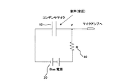
次に本発明の実施形態に係るチャージポンプ回路について図面を参照しながら説明する。図1は、このチャージポンプ回路が応用されるコンデンサマイクシステムの回路図である。半導体チップ上に一対の容量電極とそれらの容量電極間に容量誘電体が介在されてなるコンデンサマイク10が形成され、一対の容量電極間にバイアス用電源20が抵抗30を介して接続される。一対の容量電極は外部からの音声(音圧)によって微少振動することでコンデンサマイクの容量値が微少変化する。するとコンデンサマイク10の出力信号Vもそれに応じて微少変化し、その出力信号Vをマイクアンプで増幅することで音声出力信号を得ることができる。このバイアス用電源20としてチャージポンプ回路が用いられる。
Next, a charge pump circuit according to an embodiment of the present invention will be described with reference to the drawings. FIG. 1 is a circuit diagram of a capacitor microphone system to which this charge pump circuit is applied. A
図2は、バイアス用電源20の回路図である。この回路は、N個の2倍昇圧回路(1)〜(N)を直列接続し、初段の2倍昇圧回路(1)に入力電圧Vinを印加し、最終段の2倍昇圧回路(N)からVout=Vin+N×Vddという電圧を得る。2倍昇圧回路(1)〜(N)は、入力電圧Vinに2倍昇圧回路(1)〜(N)の電源電圧Vddを加算する回路である。図2の例では、Vin=Vddに設定され、Vout=Vin×(N+1)となる。
FIG. 2 is a circuit diagram of the
次に、図2の2倍昇圧回路(1)〜(N)回路、即ち、チャージポンプ回路の具体的な回路について説明する。図3は、そのようなチャージポンプ回路の一例を示す回路図である。第1及び第2の電荷転送用MOSトランジスタM1,M2は直列接続され、それらの接続ノードに第1のポンプアップコンデンサC1の一方の端子が接続され、第1のポンプアップコンデンサC1の他方の端子にクロックドライバー(不図示)からのクロックCLKが印加されている。第1の電荷転送用MOSトランジスタM1のソースには入力端子Pinから入力電圧Vinが印加され、第2の電荷転送用MOSトランジスタM2のソースは出力端子Poutに接続されている。 Next, a specific circuit of the double booster circuits (1) to (N) in FIG. 2, that is, the charge pump circuit will be described. FIG. 3 is a circuit diagram showing an example of such a charge pump circuit. The first and second charge transfer MOS transistors M1 and M2 are connected in series, one terminal of the first pump-up capacitor C1 is connected to the connection node, and the other terminal of the first pump-up capacitor C1. Is supplied with a clock CLK from a clock driver (not shown). The input voltage Vin is applied from the input terminal Pin to the source of the first charge transfer MOS transistor M1, and the source of the second charge transfer MOS transistor M2 is connected to the output terminal Pout.
一方、第3及び第4の電荷転送用MOSトランジスタM3,M4も直列接続され、それらの接続ノードに第2のポンプアップコンデンサC2の一方の端子が接続され、第2のポンプアップコンデンサC2の他方の端子にクロックドライバー(不図示)からの反転クロック*CLK(*CLKはCLKの反転クロック)が印加されている。第3の電荷転送用MOSトランジスタM3のソースには入力端子Pinから入力電圧Vinが印加され、第4の電荷転送用MOSトランジスタM4のソースは、出力端子Poutに接続されている。 On the other hand, the third and fourth charge transfer MOS transistors M3 and M4 are also connected in series, one terminal of the second pump-up capacitor C2 is connected to the connection node thereof, and the other of the second pump-up capacitor C2 is connected. An inversion clock * CLK (* CLK is an inversion clock of CLK) from a clock driver (not shown) is applied to these terminals. The input voltage Vin is applied from the input terminal Pin to the source of the third charge transfer MOS transistor M3, and the source of the fourth charge transfer MOS transistor M4 is connected to the output terminal Pout.
また、出力端子Poutには平滑用コンデンサCoutが接続されている。第1及び第3の電荷転送用MOSトランジスタM1,M3はNチャネル型、第2及び第4の電荷転送用MOSトランジスタM2,M4はPチャネル型である。クロックドライバーの電源電圧をVddとし、クロックCLK、反転クロック*CLKの振幅もそれぞれVddであるとする。 Further, a smoothing capacitor Cout is connected to the output terminal Pout. The first and third charge transfer MOS transistors M1 and M3 are N-channel type, and the second and fourth charge transfer MOS transistors M2 and M4 are P-channel type. Assume that the power supply voltage of the clock driver is Vdd, and the amplitudes of the clock CLK and the inverted clock * CLK are also Vdd.
このチャージポンプ回路の動作は以下の通りである。クロックCLKが「ハイ」の期間は、M2、M3はオンし、M1,M4はオフする。これにより、第1のポンピングコンデンサC1が放電され、第2のポンピングコンデンサC2が充電される。第1のポンピングコンデンサC1の放電電流はM2を通して流れ、出力電圧Vout=Vin+Vddが得られる。一方、クロックCLKが「ロウ」の期間は、M1、M4はオンし、M2,M3はオフする。これにより、第2のポンピングコンデンサC2が放電され、第1のポンピングコンデンサC1が充電される。第2のポンピングコンデンサC2の放電電流はM4を通して流れ、出力電圧Vout=Vin+Vddが得られる。こうして、全クロック期間を通してM2,M4のいずれかを通してポンピングコンデンサの放電電流が流れることで効率的な昇圧動作が行われる。 The operation of this charge pump circuit is as follows. During the period when the clock CLK is “high”, M2 and M3 are turned on, and M1 and M4 are turned off. As a result, the first pumping capacitor C1 is discharged and the second pumping capacitor C2 is charged. The discharge current of the first pumping capacitor C1 flows through M2, and the output voltage Vout = Vin + Vdd is obtained. On the other hand, during the period when the clock CLK is “low”, M1 and M4 are turned on, and M2 and M3 are turned off. As a result, the second pumping capacitor C2 is discharged, and the first pumping capacitor C1 is charged. The discharge current of the second pumping capacitor C2 flows through M4, and the output voltage Vout = Vin + Vdd is obtained. Thus, an efficient boosting operation is performed by the discharge current of the pumping capacitor flowing through either M2 or M4 throughout the entire clock period.
しかしながら、このチャージポンプ回路では、電荷転送用MOSトランジスタのオンオフが同時に行われるために、実際には、電荷転送用MOSトランジスタのスイッチング時に逆電流I1,I2が流れ、チャージポンプ回路の電圧損失ΔVが生じてしまう。即ち、出力電圧Vout=Vin+Vdd−ΔVとなる。 However, in this charge pump circuit, since the charge transfer MOS transistors are simultaneously turned on and off, the reverse currents I1 and I2 actually flow when the charge transfer MOS transistors are switched, and the voltage loss ΔV of the charge pump circuit is reduced. It will occur. That is, the output voltage Vout = Vin + Vdd−ΔV.
例えば、クロックCLKが「ハイ」から「ロウ」に変化するときを考えると、M2はオンからオフに、M1はオフからオンにスイッチングする。しかしながら、MOSトランジスタのスイッチングはある時間を必要とするため、過渡的には、M1とM2が同時にオンする期間が生じることは避けられない。すると、M1とM2が同時にオンしている期間に、昇圧電圧が生じている出力端子Poutから、M2、M1を通して、入力端子Pinに逆電流I1が流れてしまう。同様にして、クロックCLKが「ロウ」から「ハイ」に変化するときにも、出力端子Poutから、M4、M3を通して、入力端子Pinに逆電流I2が流れてしまう。 For example, when the clock CLK changes from “high” to “low”, M2 switches from on to off and M1 switches from off to on. However, since switching of the MOS transistor requires a certain time, it is inevitable that a period in which M1 and M2 are simultaneously turned on occurs. Then, the reverse current I1 flows from the output terminal Pout where the boosted voltage is generated to the input terminal Pin through M2 and M1 during a period in which M1 and M2 are simultaneously turned on. Similarly, when the clock CLK changes from “low” to “high”, the reverse current I2 flows from the output terminal Pout to the input terminal Pin through M4 and M3.
そこで、そのような逆電流の発生を防止したチャージポンプ回路について以下で説明する。図4は係るチャージポンプ回路の回路図である。第1及び第2の電荷転送用MOSトランジスタM11,M12は直列接続され、それらの接続ノードに第1のポンプアップコンデンサCAの一方の端子が接続され、第1のポンプアップコンデンサCAの他方の端子にクロックドライバー(不図示)からのクロックCLKが印加されている。第1の電荷転送用MOSトランジスタM11のソースには入力端子Pinから入力電圧Vinが印加され、第2の電荷転送用MOSトランジスタM12のソースは出力端子Poutに接続されている。 A charge pump circuit that prevents the occurrence of such reverse current will be described below. FIG. 4 is a circuit diagram of such a charge pump circuit. The first and second charge transfer MOS transistors M11 and M12 are connected in series, one terminal of the first pump-up capacitor CA is connected to the connection node, and the other terminal of the first pump-up capacitor CA is connected. Is supplied with a clock CLK from a clock driver (not shown). The input voltage Vin is applied from the input terminal Pin to the source of the first charge transfer MOS transistor M11, and the source of the second charge transfer MOS transistor M12 is connected to the output terminal Pout.
一方、第3及び第4の電荷転送用MOSトランジスタM13,M14も直列接続され、それらの接続ノードに第2のポンプアップコンデンサCBの一方の端子が接続され、第2のポンプアップコンデンサCBの他方の端子にクロックドライバー(不図示)からの反転クロック*CLK(*CLKはCLKの反転クロック)が印加されている。第3の電荷転送用MOSトランジスタM13のソースには入力端子Pinから入力電圧Vinが印加され、第4の電荷転送用MOSトランジスタM14のソースは出力端子Poutに接続されている。 On the other hand, the third and fourth charge transfer MOS transistors M13 and M14 are also connected in series, and one terminal of the second pump-up capacitor CB is connected to the connection node thereof, and the other of the second pump-up capacitor CB is connected. An inversion clock * CLK (* CLK is an inversion clock of CLK) from a clock driver (not shown) is applied to these terminals. The input voltage Vin is applied from the input terminal Pin to the source of the third charge transfer MOS transistor M13, and the source of the fourth charge transfer MOS transistor M14 is connected to the output terminal Pout.
また、出力端子Poutには平滑用コンデンサCoutが接続されている。第1及び第3の電荷転送用MOSトランジスタM11,M13はNチャネル型、第2及び第4の電荷転送用MOSトランジスタM12,M14はPチャネル型である。 Further, a smoothing capacitor Cout is connected to the output terminal Pout. The first and third charge transfer MOS transistors M11 and M13 are N-channel type, and the second and fourth charge transfer MOS transistors M12 and M14 are P-channel type.
第1の電荷転送用MOSトランジスタM11のゲートには第1の結合コンデンサC11を介して第1のクロックCLK(B)が供給される。また、入力端子Pinと第1の電荷転送用MOSトランジスタM11のゲートの間には第1のバイアス用MOSトランジスタM15が接続されている。一方、第3の電荷転送用MOSトランジスタM13のゲートには第3の結合コンデンサC13を介して第3のクロックCLK(C)が供給される。 The first clock CLK (B) is supplied to the gate of the first charge transfer MOS transistor M11 through the first coupling capacitor C11. A first bias MOS transistor M15 is connected between the input terminal Pin and the gate of the first charge transfer MOS transistor M11. On the other hand, the third clock CLK (C) is supplied to the gate of the third charge transfer MOS transistor M13 through the third coupling capacitor C13.
また、入力端子Pinと第3の電荷転送用MOSトランジスタM13のゲートの間には第3のバイアス用MOSトランジスタM17が接続されている。そして、第1のバイアス用MOSトランジスタM15のゲートと第3の電荷転送用MOSトランジスタM13のゲートとが互いに接続され、そして、第3のバイアス用MOSトランジスタM17のゲートと第1の電荷転送用MOSトランジスタM11のゲートとが互いに接続されている。 A third bias MOS transistor M17 is connected between the input terminal Pin and the gate of the third charge transfer MOS transistor M13. The gate of the first bias MOS transistor M15 and the gate of the third charge transfer MOS transistor M13 are connected to each other, and the gate of the third bias MOS transistor M17 and the first charge transfer MOS are connected. The gate of the transistor M11 is connected to each other.
同様に、第2の電荷転送用MOSトランジスタM12のゲートには第2の結合コンデンサC12を介して第2のクロックCLK(A)が供給される。また、出力端子Poutと第2の電荷転送用MOSトランジスタM12のゲートの間には第2のバイアス用MOSトランジスタM16が接続されている。一方、第4の電荷転送用MOSトランジスタM14のゲートには第4の結合コンデンサC14を介して第4のクロックCLK(D)が供給される。また、出力端子Poutと第4の電荷転送用MOSトランジスタM14のゲートの間には第4のバイアス用MOSトランジスタM18が接続されている。 Similarly, the second clock CLK (A) is supplied to the gate of the second charge transfer MOS transistor M12 via the second coupling capacitor C12. A second bias MOS transistor M16 is connected between the output terminal Pout and the gate of the second charge transfer MOS transistor M12. On the other hand, the fourth clock CLK (D) is supplied to the gate of the fourth charge transfer MOS transistor M14 via the fourth coupling capacitor C14. A fourth bias MOS transistor M18 is connected between the output terminal Pout and the gate of the fourth charge transfer MOS transistor M14.
そして、第2のバイアス用MOSトランジスタM16のゲートと第4の電荷転送用MOSトランジスタM14のゲートとが互いに接続され、そして、第4のバイアス用MOSトランジスタM18のゲートと第2の電荷転送用MOSトランジスタM12のゲートとが互いに接続されている。 The gate of the second bias MOS transistor M16 and the gate of the fourth charge transfer MOS transistor M14 are connected to each other, and the gate of the fourth bias MOS transistor M18 and the second charge transfer MOS transistor are connected. The gate of the transistor M12 is connected to each other.
さらに、第1の電荷転送用MOSトランジスタM11のゲートと出力端子Poutとの間には第1の初期電圧設定用ダイオードD1が接続されている。即ち、第1の初期電圧設定用ダイオードD1のアノードが第1の電荷転送用MOSトランジスタM11のゲートに接続され、第1の初期電圧設定用ダイオードD1のカソードが出力端子Poutに接続されている。同様に、第3の電荷転送用MOSトランジスタM13のゲートと出力端子Poutとの間には第3の初期電圧設定用ダイオードD3が接続されている。 Further, a first initial voltage setting diode D1 is connected between the gate of the first charge transfer MOS transistor M11 and the output terminal Pout. That is, the anode of the first initial voltage setting diode D1 is connected to the gate of the first charge transfer MOS transistor M11, and the cathode of the first initial voltage setting diode D1 is connected to the output terminal Pout. Similarly, a third initial voltage setting diode D3 is connected between the gate of the third charge transfer MOS transistor M13 and the output terminal Pout.
即ち、第3の初期電圧設定用ダイオードD3のアノードが第3の電荷転送用MOSトランジスタM13のゲートに接続され、第3の初期電圧設定用ダイオードD3のカソードが出力端子Poutに接続されている。 That is, the anode of the third initial voltage setting diode D3 is connected to the gate of the third charge transfer MOS transistor M13, and the cathode of the third initial voltage setting diode D3 is connected to the output terminal Pout.
また、第2の電荷転送用MOSトランジスタM12のゲートと入力端子Pinとの間には第2の初期電圧設定用ダイオードD2が接続されている。即ち、第2の初期電圧設定用ダイオードD2のカソードが第2の電荷転送用MOSトランジスタM12のゲートに接続され、第2の初期電圧設定用ダイオードD2のアノードが入力端子Pinに接続されている。同様に、第4の電荷転送用MOSトランジスタM14のゲートと入力端子Pinとの間には第4の初期電圧設定用ダイオードD4が接続されている。 A second initial voltage setting diode D2 is connected between the gate of the second charge transfer MOS transistor M12 and the input terminal Pin. That is, the cathode of the second initial voltage setting diode D2 is connected to the gate of the second charge transfer MOS transistor M12, and the anode of the second initial voltage setting diode D2 is connected to the input terminal Pin. Similarly, a fourth initial voltage setting diode D4 is connected between the gate of the fourth charge transfer MOS transistor M14 and the input terminal Pin.
即ち、第4の初期電圧設定用ダイオードD4のカソードが第4の電荷転送用MOSトランジスタM14のゲートに接続され、第4の初期電圧設定用ダイオードD4のアノードが入力端子Pinに接続されている。 That is, the cathode of the fourth initial voltage setting diode D4 is connected to the gate of the fourth charge transfer MOS transistor M14, and the anode of the fourth initial voltage setting diode D4 is connected to the input terminal Pin.
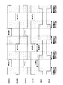
次に上述した図4のチャージポンプ回路の動作について図面を参照しながら説明する。図5はこのチャージポンプ回路のクロックタイミング図、図6は、図5の状態A(M12,M13がオンの状態)における動作を説明する回路図、図7は図5の状態B(M11,M14がオンの状態)における動作を説明する回路図である。 Next, the operation of the above-described charge pump circuit of FIG. 4 will be described with reference to the drawings. FIG. 5 is a clock timing diagram of this charge pump circuit, FIG. 6 is a circuit diagram for explaining the operation in the state A of FIG. 5 (M12, M13 is on), and FIG. 7 is the state B (M11, M14 of FIG. 5). It is a circuit diagram explaining the operation | movement in the state of ON.
このチャージポンプ回路の動作の要点は、図5に示す如く、第1乃至第4電荷転送用MOSトランジスタM11,M12,M13,M14を全てオフさせた状態で、クロックドライバーからのクロックCLK、*CLKをロウからハイへ、もしくはハイからロウへ変化させ、その後、第2の電荷転送用MOSトランジスタM12をオンさせて第1のポンピングコンデンサCAを放電し、第3のMOSトランジスタM13をオンさせて第2のポンピングコンデンサCBを充電する(状態A)。 As shown in FIG. 5, the main points of the operation of this charge pump circuit are the clocks CLK, * CLK from the clock driver with the first to fourth charge transfer MOS transistors M11, M12, M13, M14 all turned off. Is changed from low to high, or from high to low, and then the second charge transfer MOS transistor M12 is turned on to discharge the first pumping capacitor CA and the third MOS transistor M13 is turned on. 2 pumping capacitor CB is charged (state A).
次に、第1乃至第4電荷転送用MOSトランジスタM11,M12,M13,M14を再び全てオフさせた状態で、クロックドライバーからのクロックCLK、*CLKをロウからハイへ、もしくはハイからロウへ変化させ、その後、第4の電荷転送用MOSトランジスタM14をオンさせて第2のポンピングコンデンサCBを放電し、第1のMOSトランジスタM11をオンさせて第1のポンピングコンデンサCAを充電する(状態B)。 Next, with all the first to fourth charge transfer MOS transistors M11, M12, M13, and M14 turned off again, the clock CLK, * CLK from the clock driver changes from low to high or from high to low. Thereafter, the fourth charge transfer MOS transistor M14 is turned on to discharge the second pumping capacitor CB, and the first MOS transistor M11 is turned on to charge the first pumping capacitor CA (state B). .
こうすることで、第1の電荷転送用MOSトランジスタM11と第2の電荷転送用MOSトランジスタM12が同時にオンすることがなく、同様に、第3の電荷転送用MOSトランジスタM13と第4の電荷転送用MOSトランジスタM13が同時にオンすることがなくなるので、逆電流の発生を完全に防止することができる。 Thus, the first charge transfer MOS transistor M11 and the second charge transfer MOS transistor M12 are not turned on at the same time. Similarly, the third charge transfer MOS transistor M13 and the fourth charge transfer MOS transistor M12 are not turned on. Since the MOS transistor M13 does not turn on at the same time, the generation of reverse current can be completely prevented.
次に、チャージポンプ回路の動作について詳しく説明する。以下の説明では、第1乃至第4の電荷転送用MOSトランジスタM11,M12,M13,M14を単に、M11,M12,M13,M14と、第1乃至第4のバイアス用MOSトランジスタM15,M16,M17,M18を単に、M15,M16,M17,M18と記載する。 Next, the operation of the charge pump circuit will be described in detail. In the following description, the first to fourth charge transfer MOS transistors M11, M12, M13, and M14 are simply referred to as M11, M12, M13, and M14, and the first to fourth bias MOS transistors M15, M16, and M17. , M18 are simply described as M15, M16, M17, and M18.
また、クロックドライバーの電源電圧をVddとし、クロックCLK、*CLKのハイレベルはVdd、ロウレベルはVss(接地電圧)であるとする。また、同様に、第1乃至第4のクロックCLK(B),CLK(A),CLK(C),CLK(D)のハイレベルはVdd、ロウレベルはVss(接地電圧)であるとする。また、入力端子Pinには入力電圧Vinが印加されている。 The power supply voltage of the clock driver is Vdd, the high level of the clocks CLK and * CLK is Vdd, and the low level is Vss (ground voltage). Similarly, the high level of the first to fourth clocks CLK (B), CLK (A), CLK (C), and CLK (D) is Vdd, and the low level is Vss (ground voltage). An input voltage Vin is applied to the input terminal Pin.
まず、M11,M12,M13,M14を全てオフさせた状態で、クロックドライバーからのクロックCLKをロウからハイへ、反転クロック*CLKをハイからロウへ変化させる。すると、M11とM12の接続ノードの電圧はVinからVin+Vddに変化し、M13とM14の接続ノードの電圧はVin+VddからVinに変化する。 First, with all of M11, M12, M13, and M14 turned off, the clock CLK from the clock driver is changed from low to high, and the inverted clock * CLK is changed from high to low. Then, the voltage at the connection node of M11 and M12 changes from Vin to Vin + Vdd, and the voltage at the connection node of M13 and M14 changes from Vin + Vdd to Vin.
次に、第2のクロックCLK(A)をハイからロウへ変化させ、これと同時に第3のクロックCLK(C)をロウからハイへ変化させる。すると、チャージポンプ回路は、図5の状態Aとなる。この状態の回路動作を、図6を参照して説明する。 Next, the second clock CLK (A) is changed from high to low, and at the same time, the third clock CLK (C) is changed from low to high. Then, the charge pump circuit is in state A in FIG. The circuit operation in this state will be described with reference to FIG.
第2のクロックCLK(A)をハイからロウへ変化させると、M12,M18のゲート電圧はVinになり、M12及びM18がオンする。M12がオンすることで第1のポンピングコンデンサCAの電荷が出力端子Poutへ放電される。これにより、出力端子Pinに出力電圧Vout=Vin+Voutが得られる。また、M18がオンすることでM14のゲート電圧は出力電圧Voutと同じVin+Voutになるので、M14はオフする。 When the second clock CLK (A) is changed from high to low, the gate voltages of M12 and M18 become Vin, and M12 and M18 are turned on. When M12 is turned on, the charge of the first pumping capacitor CA is discharged to the output terminal Pout. Thereby, the output voltage Vout = Vin + Vout is obtained at the output terminal Pin. Further, when M18 is turned on, the gate voltage of M14 becomes Vin + Vout which is the same as the output voltage Vout, so that M14 is turned off.
一方、第3のクロックCLK(C)をロウからハイへ変化させると、M13,M15のゲート電圧はVin+Vddになり、M13及びM15がオンする。M13がオンすることで第2のポンピングコンデンサCBが充電される。また、M15がオンすることでM11のゲート電圧はVinになるので、M11はオフする。 On the other hand, when the third clock CLK (C) is changed from low to high, the gate voltages of M13 and M15 become Vin + Vdd, and M13 and M15 are turned on. When M13 is turned on, the second pumping capacitor CB is charged. Further, when M15 is turned on, the gate voltage of M11 becomes Vin, so that M11 is turned off.
次に、再び、M11,M12,M13,M14を全てオフさせた状態で、クロックドライバーからのクロックCLKをハイからロウへ、反転クロック*CLKをロウからハイへ変化させる。すると、M11とM12の接続ノードの電圧はVin+VddからVinに変化し、M3とM4の接続ノードの電圧はVinからVin+Vddに変化する。 Next, again, with all of M11, M12, M13, and M14 turned off, the clock CLK from the clock driver is changed from high to low, and the inverted clock * CLK is changed from low to high. Then, the voltage at the connection node between M11 and M12 changes from Vin + Vdd to Vin, and the voltage at the connection node between M3 and M4 changes from Vin to Vin + Vdd.
次に、第1のクロックCLK(B)をロウからハイへ変化させ、これと同時に第4のクロックCLK(D)をハイからロウへ変化させる。すると、チャージポンプ回路は、図5の状態Bとなる。この状態の回路動作を、図7を参照して説明する。
第1のクロックCLK(B)をロウからハイへ変化させると、M11,M17のゲート電圧はVin+Vddになり、M11及びM17がオンする。M11がオンすることで第1のポンピングコンデンサCAが充電される。また、M17がオンすることでM13のゲート電圧は入力電圧Vinになるので、M13はオフする。
Next, the first clock CLK (B) is changed from low to high, and at the same time, the fourth clock CLK (D) is changed from high to low. Then, the charge pump circuit is in a state B in FIG. The circuit operation in this state will be described with reference to FIG.
When the first clock CLK (B) is changed from low to high, the gate voltages of M11 and M17 become Vin + Vdd, and M11 and M17 are turned on. When M11 is turned on, the first pumping capacitor CA is charged. Further, when M17 is turned on, the gate voltage of M13 becomes the input voltage Vin, so that M13 is turned off.
一方、第4のクロックCLK(D)をハイからロウへ変化させると、M14,M16のゲート電圧はVinになり、M14及びM16がオンする。M14がオンすることで第2のポンピングコンデンサCBの電荷が出力端子Poutへ放電される。これにより、出力端子Pinに出力電圧Vout=Vin+Voutが得られる。また、M16がオンすることでM12のゲート電圧は出力電圧Voutと同じVin+Voutになるので、M12はオフする。 On the other hand, when the fourth clock CLK (D) is changed from high to low, the gate voltages of M14 and M16 become Vin, and M14 and M16 are turned on. When M14 is turned on, the charge of the second pumping capacitor CB is discharged to the output terminal Pout. Thereby, the output voltage Vout = Vin + Vout is obtained at the output terminal Pin. Further, when M16 is turned on, the gate voltage of M12 becomes Vin + Vout which is the same as the output voltage Vout, so that M12 is turned off.
次に、第1乃至第4の初期電圧設定用ダイオードD1,D2,D3,D4の動作について図8を参照して説明する。第1及び第2の初期電圧設定用ダイオードD1,D3がない場合、図中のノードA又はA’の初期値がVout+Vtn以上であると、M15,M17のいずれか一方が常にオンし、他方が常にオフするため回路が動作しない。VtnはM15,M17のしきい値電圧である。 Next, operations of the first to fourth initial voltage setting diodes D1, D2, D3, and D4 will be described with reference to FIG. When the first and second initial voltage setting diodes D1 and D3 are not provided, if the initial value of the node A or A ′ in the figure is equal to or higher than Vout + Vtn, one of M15 and M17 is always on and the other is The circuit does not operate because it is always off. Vtn is a threshold voltage of M15 and M17.
例えばノードAの初期値がVout+Vtn以上であるとする。すると、M15のゲート電圧もVout+Vtn以上であり、常にオン状態である。また、ノードA’は常にVinとなるため、M17のゲート電圧も常にVinであり、M17は常にオフ状態である。そこで、第1及び第2の初期電圧設定用ダイオードD1,D2を設けることで、ノードA,A’がVout以上である場合には、ダイオードの順方向電流が流れ、ノードA,A’の電圧を下げるようにした。 For example, it is assumed that the initial value of the node A is Vout + Vtn or more. Then, the gate voltage of M15 is also equal to or higher than Vout + Vtn and is always on. Further, since the node A ′ is always Vin, the gate voltage of M17 is always Vin, and M17 is always in the off state. Therefore, by providing the first and second initial voltage setting diodes D1 and D2, when the nodes A and A ′ are equal to or higher than Vout, the forward current of the diode flows, and the voltages of the nodes A and A ′ Was lowered.
一方、第3及び第4の初期電圧設定用ダイオードD2,D4がない場合、図中のノードB又はB’の初期値がVout+Vtp以下であると、M16,M18のいずれか一方が常にオンし、他方が常にオフするため回路が動作しない。VtpはM16,M18のしきい値電圧である。例えばノードBの初期値がVout+Vtp以下であるとする。すると、M18のゲート電圧もVout+Vtp以下であり、常にオン状態である。 On the other hand, when the third and fourth initial voltage setting diodes D2 and D4 are not provided, if the initial value of the node B or B ′ in the figure is equal to or lower than Vout + Vtp, one of M16 and M18 is always turned on. Since the other is always off, the circuit does not operate. Vtp is the threshold voltage of M16 and M18. For example, it is assumed that the initial value of the node B is Vout + Vtp or less. Then, the gate voltage of M18 is also equal to or lower than Vout + Vtp, and is always on.
また、ノードB’は常にVoutとなるため、M16のゲート電圧も常にVoutであり、M16は常にオフ状態である。そこで、第3及び第4の初期電圧設定用ダイオードD3,D4を設けることで、ノードB,B’がVout以下である場合には、ダイオードの順方向電流が流れ、ノードB,B’の電圧を上げるようにした。 Further, since the node B ′ is always Vout, the gate voltage of M16 is always Vout, and M16 is always in the off state. Therefore, by providing the third and fourth initial voltage setting diodes D3 and D4, when the nodes B and B ′ are equal to or lower than Vout, the forward current of the diode flows, and the voltages at the nodes B and B ′ I tried to raise.
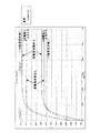
図9は、本実施形態のチャージポンプ回路の出力電圧Voutの回路シミュレーション結果を示す図である。逆電流対策なしの回路(図3の回路)では、逆電流による電圧損失が生じるが、逆電流対策ありの回路(図4の回路)ではそのような電圧損失が防止されていることがわかる。 FIG. 9 is a diagram illustrating a circuit simulation result of the output voltage Vout of the charge pump circuit according to the present embodiment. In the circuit without the countermeasure against reverse current (the circuit in FIG. 3), voltage loss due to the reverse current occurs, but in the circuit with the countermeasure against reverse current (the circuit in FIG. 4), such a voltage loss is prevented.
10 コンデンサマイク 20 バイアス用電源 30 抵抗
M1 第1の電荷転送用MOSトランジスタ
M2 第2の電荷転送用MOSトランジスタ
M3 第3の電荷転送用MOSトランジスタ
M4 第4の電荷転送用MOSトランジスタ
C1 第1のポンピングコンデンサ
C2 第2のポンピングコンデンサ
M11 第1の電荷転送用MOSトランジスタ
M12 第2の電荷転送用MOSトランジスタ
M13 第3の電荷転送用MOSトランジスタ
M14 第4の電荷転送用MOSトランジスタ
CA 第1のポンピングコンデンサ
CB 第2のポンピングコンデンサ
M15 第1のバイアス用MOSトランジスタ
M16 第2のバイアス用MOSトランジスタ
M17 第3のバイアス用MOSトランジスタ
M18 第4のバイアス用MOSトランジスタ
C11 第1のカップリングコンデンサ
C12 第2のカップリングコンデンサ
C13 第3のカップリングコンデンサ
C14 第4のカップリングコンデンサ
DESCRIPTION OF
Claims (6)
前記第1の電荷転送用MOSトランジスタと前記第2の電荷転送用MOSトランジスタの接続点に一方の端子が接続された第1のコンデンサと、
直列に接続された第3及び第4の電荷転送用MOSトランジスタと、
前記第3の電荷転送用MOSトランジスタと前記第4の電荷転送用MOSトランジスタの接続点に一方の端子が接続された第2のコンデンサと、
前記第1のコンデンサの他方の端子と前記第2のコンデンサの他方に端子に相補的なクロックを供給するクロックドライバーと、
前記第1及び第3の電荷転送用MOSトランジスタが接続された入力端子に入力電圧を供給する電圧源と、
前記第1乃至第4の電荷転送用MOSトランジスタを全てオフさせた状態で前記クロックドライバーのクロックの電圧レベルを反転させ、その後、前記第2及び第3の電荷転送用MOSトランジスタをオンさせ、その後、前記第1乃至第4の電荷転送用MOSトランジスタを全てオフさせた状態で前記クロックドライバーのクロックの電圧レベルを更に反転させ、その後、前記第1及び第4の電荷転送用MOSトランジスタをオンさせるように制御する制御回路と、
前記第2及び第4の電荷転送用MOSトランジスタが接続された出力端子から前記入力電圧が昇圧された出力電圧を出力する出力回路と、
前記第1の電荷転送用MOSトランジスタ及び前記第3の電荷転送用MOSトランジスタのゲートの電圧の初期値が所定値以上にならないように電圧設定する初期電圧設定回路と、を備え、
前記制御回路は、第1の電荷転送用MOSトランジスタのゲートに第1の結合コンデンサを介して第1のクロックを供給する第1のクロック供給手段と、
前記第1の電荷転送用MOSトランジスタのゲートに前記入力電圧を供給する第1のバイアス用MOSトランジスタと、
第3の電荷転送用MOSトランジスタのゲートに第3の結合コンデンサを介して第3のクロックを供給する第3のクロック供給手段と、
前記第3の電荷転送用MOSトランジスタのゲートに前記入力電圧を供給する第3のバイアス用MOSトランジスタと、を有し、前記第1のクロックが第1のレベルから第2のレベルに変化すると前記第1の電荷転送用MOSトランジスタ及び前記第3のバイアス用MOSトランジスタがオンし、前記第3の電荷転送用MOSトランジスタがオフし、次に、前記第3のクロックが第1のレベルから第2のレベルに変化すると前記第3の電荷転送用MOSトランジスタ及び前記第1のバイアス用MOSトランジスタがオンし、前記第1の電荷転送用MOSトランジスタがオフするように制御することを特徴とするチャージポンプ回路。 First and second charge transfer MOS transistors connected in series;
A first capacitor having one terminal connected to a connection point between the first charge transfer MOS transistor and the second charge transfer MOS transistor;
Third and fourth charge transfer MOS transistors connected in series;
A second capacitor having one terminal connected to a connection point between the third charge transfer MOS transistor and the fourth charge transfer MOS transistor;
A clock driver that supplies a complementary clock to the other terminal of the first capacitor and the other terminal of the second capacitor;
A voltage source for supplying an input voltage to an input terminal to which the first and third charge transfer MOS transistors are connected;
The voltage level of the clock of the clock driver is inverted with all of the first to fourth charge transfer MOS transistors turned off, and then the second and third charge transfer MOS transistors are turned on. The voltage level of the clock of the clock driver is further inverted with all of the first to fourth charge transfer MOS transistors turned off, and then the first and fourth charge transfer MOS transistors are turned on. A control circuit to control,
An output circuit that outputs an output voltage obtained by boosting the input voltage from an output terminal to which the second and fourth charge transfer MOS transistors are connected;
An initial voltage setting circuit that sets a voltage so that an initial value of a gate voltage of the first charge transfer MOS transistor and the third charge transfer MOS transistor does not exceed a predetermined value;
The control circuit includes first clock supply means for supplying a first clock to the gate of the first charge transfer MOS transistor via a first coupling capacitor;
A first bias MOS transistor for supplying the input voltage to a gate of the first charge transfer MOS transistor;
Third clock supply means for supplying a third clock to the gate of the third charge transfer MOS transistor via a third coupling capacitor;
A third bias MOS transistor for supplying the input voltage to the gate of the third charge transfer MOS transistor, and when the first clock changes from the first level to the second level, The first charge transfer MOS transistor and the third bias MOS transistor are turned on, the third charge transfer MOS transistor is turned off, and then the third clock is changed from the first level to the second level. The charge pump is controlled to turn on the third charge transfer MOS transistor and the first bias MOS transistor and to turn off the first charge transfer MOS transistor. circuit.
前記第2の電荷転送用MOSトランジスタのゲートに前記出力電圧を供給する第2のバイ
アス用MOSトランジスタと、
第4の電荷転送用MOSトランジスタのゲートに第4の結合コンデンサを介して第4のクロックを供給する第4のクロック供給手段と、
前記第4の電荷転送用MOSトランジスタのゲートに前記出力電圧を供給する第4のバイアス用MOSトランジスタと、を有し、
前記第2のクロックが第1のレベルから第2のレベルに変化すると前記第2の電荷転送用MOSトランジスタ及び前記第4のバイアス用MOSトランジスタがオンし、前記第4の電荷転送用MOSトランジスタがオフし、次に、前記第4のクロックが第1のレベルから第2のレベルに変化すると前記第4の電荷転送用MOSトランジスタ及び前記第2のバイアス用MOSトランジスタがオンし、前記第2の電荷転送用MOSトランジスタがオフするように制御することを特徴とする請求項2に記載のチャージポンプ回路。 The control circuit includes a second clock supply means for supplying a second clock to the gate of the second charge transfer MOS transistor via a second coupling capacitor;
A second bias MOS transistor for supplying the output voltage to the gate of the second charge transfer MOS transistor;
Fourth clock supply means for supplying a fourth clock to the gate of the fourth charge transfer MOS transistor via a fourth coupling capacitor;
A fourth bias MOS transistor for supplying the output voltage to the gate of the fourth charge transfer MOS transistor;
When the second clock changes from the first level to the second level, the second charge transfer MOS transistor and the fourth bias MOS transistor are turned on, and the fourth charge transfer MOS transistor is turned on. Next, when the fourth clock changes from the first level to the second level, the fourth charge transfer MOS transistor and the second bias MOS transistor are turned on, and the second clock MOS transistor is turned on. 3. The charge pump circuit according to claim 2, wherein the charge transfer MOS transistor is controlled to be turned off.
Priority Applications (5)
| Application Number | Priority Date | Filing Date | Title |
|---|---|---|---|
| JP2004092639A JP4557577B2 (en) | 2004-03-26 | 2004-03-26 | Charge pump circuit |
| TW094108303A TWI264872B (en) | 2004-03-26 | 2005-03-18 | Charge pump circuit |
| KR1020050024410A KR100684244B1 (en) | 2004-03-26 | 2005-03-24 | Charge pump circuit |
| US11/089,031 US7208996B2 (en) | 2004-03-26 | 2005-03-25 | Charge pump circuit |
| CN2005100624379A CN1674444B (en) | 2004-03-26 | 2005-03-28 | Charge pump circuit |
Applications Claiming Priority (1)
| Application Number | Priority Date | Filing Date | Title |
|---|---|---|---|
| JP2004092639A JP4557577B2 (en) | 2004-03-26 | 2004-03-26 | Charge pump circuit |
Publications (2)
| Publication Number | Publication Date |
|---|---|
| JP2005278378A JP2005278378A (en) | 2005-10-06 |
| JP4557577B2 true JP4557577B2 (en) | 2010-10-06 |
Family
ID=34989841
Family Applications (1)
| Application Number | Title | Priority Date | Filing Date |
|---|---|---|---|
| JP2004092639A Expired - Fee Related JP4557577B2 (en) | 2004-03-26 | 2004-03-26 | Charge pump circuit |
Country Status (5)
| Country | Link |
|---|---|
| US (1) | US7208996B2 (en) |
| JP (1) | JP4557577B2 (en) |
| KR (1) | KR100684244B1 (en) |
| CN (1) | CN1674444B (en) |
| TW (1) | TWI264872B (en) |
Families Citing this family (48)
| Publication number | Priority date | Publication date | Assignee | Title |
|---|---|---|---|---|
| EP1881589A1 (en) * | 2006-07-19 | 2008-01-23 | STMicroelectronics S.r.l. | Charge pump circuit |
| JP4642794B2 (en) * | 2007-03-27 | 2011-03-02 | エプソンイメージングデバイス株式会社 | Power supply circuit and display device |
| US8044705B2 (en) * | 2007-08-28 | 2011-10-25 | Sandisk Technologies Inc. | Bottom plate regulation of charge pumps |
| US20090066407A1 (en) * | 2007-09-12 | 2009-03-12 | Rochester Institute Of Technology | Charge pump systems and methods thereof |
| US7595683B1 (en) * | 2007-11-15 | 2009-09-29 | Fairchild Semiconductor Corporation | Low-input-voltage charge pump |
| JP5096198B2 (en) * | 2008-03-18 | 2012-12-12 | 株式会社リコー | Voltage generation circuit |
| WO2009135815A1 (en) * | 2008-05-05 | 2009-11-12 | Epcos Ag | Fast precision charge pump |
| US7969235B2 (en) * | 2008-06-09 | 2011-06-28 | Sandisk Corporation | Self-adaptive multi-stage charge pump |
| US8710907B2 (en) * | 2008-06-24 | 2014-04-29 | Sandisk Technologies Inc. | Clock generator circuit for a charge pump |
| KR101447917B1 (en) | 2008-08-01 | 2014-10-14 | 삼성전자주식회사 | Semiconductor device for pumping charge |
| JP5180793B2 (en) * | 2008-11-28 | 2013-04-10 | キヤノン株式会社 | Clock generation circuit, integrated circuit, and imaging sensor |
| US8076968B1 (en) | 2009-03-09 | 2011-12-13 | Fairchild Semiconductor Corporation | Low-input-voltage charge pump |
| US8154333B2 (en) * | 2009-04-01 | 2012-04-10 | Taiwan Semiconductor Manufacturing Company, Ltd. | Charge pump circuits, systems, and operational methods thereof |
| US7973592B2 (en) * | 2009-07-21 | 2011-07-05 | Sandisk Corporation | Charge pump with current based regulation |
| US8339183B2 (en) * | 2009-07-24 | 2012-12-25 | Sandisk Technologies Inc. | Charge pump with reduced energy consumption through charge sharing and clock boosting suitable for high voltage word line in flash memories |
| US20110133820A1 (en) * | 2009-12-09 | 2011-06-09 | Feng Pan | Multi-Stage Charge Pump with Variable Number of Boosting Stages |
| US20110148509A1 (en) * | 2009-12-17 | 2011-06-23 | Feng Pan | Techniques to Reduce Charge Pump Overshoot |
| CN101807915B (en) * | 2010-04-15 | 2012-05-30 | 复旦大学 | Phase frequency detector and charge pump circuits applying to integral frequency division phase-locked loop |
| JP2012115046A (en) * | 2010-11-25 | 2012-06-14 | Renesas Electronics Corp | Charge pump circuit |
| US8339185B2 (en) | 2010-12-20 | 2012-12-25 | Sandisk 3D Llc | Charge pump system that dynamically selects number of active stages |
| US8294509B2 (en) | 2010-12-20 | 2012-10-23 | Sandisk Technologies Inc. | Charge pump systems with reduction in inefficiencies due to charge sharing between capacitances |
| US8699247B2 (en) | 2011-09-09 | 2014-04-15 | Sandisk Technologies Inc. | Charge pump system dynamically reconfigurable for read and program |
| US8400212B1 (en) | 2011-09-22 | 2013-03-19 | Sandisk Technologies Inc. | High voltage charge pump regulation system with fine step adjustment |
| US8514628B2 (en) | 2011-09-22 | 2013-08-20 | Sandisk Technologies Inc. | Dynamic switching approach to reduce area and power consumption of high voltage charge pumps |
| US8710909B2 (en) | 2012-09-14 | 2014-04-29 | Sandisk Technologies Inc. | Circuits for prevention of reverse leakage in Vth-cancellation charge pumps |
| WO2014100184A1 (en) * | 2012-12-19 | 2014-06-26 | Knowles Electronics, Llc | Apparatus and method for high voltage i/o electro-static discharge protection |
| US8836412B2 (en) | 2013-02-11 | 2014-09-16 | Sandisk 3D Llc | Charge pump with a power-controlled clock buffer to reduce power consumption and output voltage ripple |
| US8981835B2 (en) | 2013-06-18 | 2015-03-17 | Sandisk Technologies Inc. | Efficient voltage doubler |
| US9024680B2 (en) | 2013-06-24 | 2015-05-05 | Sandisk Technologies Inc. | Efficiency for charge pumps with low supply voltages |
| US9077238B2 (en) | 2013-06-25 | 2015-07-07 | SanDisk Technologies, Inc. | Capacitive regulation of charge pumps without refresh operation interruption |
| US9007046B2 (en) | 2013-06-27 | 2015-04-14 | Sandisk Technologies Inc. | Efficient high voltage bias regulation circuit |
| US9083231B2 (en) | 2013-09-30 | 2015-07-14 | Sandisk Technologies Inc. | Amplitude modulation for pass gate to improve charge pump efficiency |
| US9154027B2 (en) | 2013-12-09 | 2015-10-06 | Sandisk Technologies Inc. | Dynamic load matching charge pump for reduced current consumption |
| US9531262B2 (en) * | 2014-01-03 | 2016-12-27 | Analog Devices Global | Charge pump |
| DE102014115433A1 (en) * | 2014-10-23 | 2016-05-12 | Infineon Technologies Ag | charge pump |
| US11611276B2 (en) | 2014-12-04 | 2023-03-21 | Taiwan Semiconductor Manufacturing Company, Ltd. | Charge pump circuit |
| US9491151B2 (en) | 2015-01-07 | 2016-11-08 | Ememory Technology Inc. | Memory apparatus, charge pump circuit and voltage pumping method thereof |
| US9831860B2 (en) * | 2015-03-16 | 2017-11-28 | Taiwan Semiconductor Manufacturing Company, Ltd. | Clock generation circuit |
| US9917507B2 (en) | 2015-05-28 | 2018-03-13 | Sandisk Technologies Llc | Dynamic clock period modulation scheme for variable charge pump load currents |
| US9602921B2 (en) | 2015-06-24 | 2017-03-21 | Robert Bosch Gmbh | Independently charge pumps for differential microphone |
| US9647536B2 (en) | 2015-07-28 | 2017-05-09 | Sandisk Technologies Llc | High voltage generation using low voltage devices |
| US9520776B1 (en) | 2015-09-18 | 2016-12-13 | Sandisk Technologies Llc | Selective body bias for charge pump transfer switches |
| CN105720813A (en) * | 2016-04-22 | 2016-06-29 | 中国科学院微电子研究所 | Charge pump circuit |
| CN105743328B (en) * | 2016-04-28 | 2019-02-01 | 广东合微集成电路技术有限公司 | A kind of transistor, charge pump components and charge pump |
| CN107181403A (en) * | 2017-05-31 | 2017-09-19 | 成都锐成芯微科技股份有限公司 | Differential charge pump circuit |
| US10461635B1 (en) * | 2018-05-15 | 2019-10-29 | Analog Devices Global Unlimited Company | Low VIN high efficiency chargepump |
| JP6783879B2 (en) * | 2019-01-29 | 2020-11-11 | ウィンボンド エレクトロニクス コーポレーション | Charge pump circuit |
| EP3819905A1 (en) * | 2019-11-05 | 2021-05-12 | EM Microelectronic-Marin SA | Gate controller for a change pump converter |
Citations (1)
| Publication number | Priority date | Publication date | Assignee | Title |
|---|---|---|---|---|
| JP2003100077A (en) * | 2001-09-27 | 2003-04-04 | Sony Corp | Boosting potential generating circuit |
Family Cites Families (10)
| Publication number | Priority date | Publication date | Assignee | Title |
|---|---|---|---|---|
| KR100243004B1 (en) * | 1997-02-27 | 2000-03-02 | 김영환 | Bootstrap charge pump circuit |
| JP3385960B2 (en) * | 1998-03-16 | 2003-03-10 | 日本電気株式会社 | Negative voltage charge pump circuit |
| JP4026947B2 (en) * | 1998-08-24 | 2007-12-26 | 株式会社ルネサステクノロジ | Booster circuit |
| US6429723B1 (en) * | 1999-11-18 | 2002-08-06 | Texas Instruments Incorporated | Integrated circuit with charge pump and method |
| JP2001211637A (en) | 2000-01-21 | 2001-08-03 | Haruo Kobayashi | Charging pump circuit |
| JP2002208290A (en) * | 2001-01-09 | 2002-07-26 | Mitsubishi Electric Corp | Charge pump circuit and operating method for non- volatile memory using it |
| JP2003033006A (en) | 2001-07-18 | 2003-01-31 | Sanyo Electric Co Ltd | Charge pump circuit |
| ITMI20012789A1 (en) * | 2001-12-21 | 2003-06-21 | St Microelectronics Srl | LOADING PUMP SYSTEM |
| JP2003284325A (en) | 2002-03-20 | 2003-10-03 | Sanyo Electric Co Ltd | Charge pump circuit and display unit having charge pump circuit |
| FR2864271B1 (en) * | 2003-12-19 | 2006-03-03 | Atmel Corp | HIGH EFFICIENCY, LOW COST LOAD PUMP CIRCUIT |
-
2004
- 2004-03-26 JP JP2004092639A patent/JP4557577B2/en not_active Expired - Fee Related
-
2005
- 2005-03-18 TW TW094108303A patent/TWI264872B/en not_active IP Right Cessation
- 2005-03-24 KR KR1020050024410A patent/KR100684244B1/en not_active IP Right Cessation
- 2005-03-25 US US11/089,031 patent/US7208996B2/en active Active
- 2005-03-28 CN CN2005100624379A patent/CN1674444B/en active Active
Patent Citations (1)
| Publication number | Priority date | Publication date | Assignee | Title |
|---|---|---|---|---|
| JP2003100077A (en) * | 2001-09-27 | 2003-04-04 | Sony Corp | Boosting potential generating circuit |
Also Published As
| Publication number | Publication date |
|---|---|
| CN1674444A (en) | 2005-09-28 |
| CN1674444B (en) | 2010-05-12 |
| TW200603540A (en) | 2006-01-16 |
| JP2005278378A (en) | 2005-10-06 |
| US20050213781A1 (en) | 2005-09-29 |
| TWI264872B (en) | 2006-10-21 |
| KR100684244B1 (en) | 2007-02-20 |
| KR20060044671A (en) | 2006-05-16 |
| US7208996B2 (en) | 2007-04-24 |
Similar Documents
| Publication | Publication Date | Title |
|---|---|---|
| JP4557577B2 (en) | Charge pump circuit | |
| TW578377B (en) | Charge-pump circuit and method for controlling the same | |
| JPH10199281A (en) | Step-up circuit and ic-card provided therewith | |
| KR20050072145A (en) | Booster circuit | |
| JP5566568B2 (en) | Power supply voltage generation circuit | |
| JPH09198887A (en) | High voltage generation circuit | |
| JP4299857B2 (en) | Boost charge pump circuit | |
| KR20070032927A (en) | Semiconductor device having charge pump type boost circuit | |
| US8421522B2 (en) | High voltage generator and method of generating high voltage | |
| JP2015142449A (en) | charge pump circuit | |
| US7683699B2 (en) | Charge pump | |
| KR100403528B1 (en) | Charge pump circuit and method of controlling the same | |
| US11114937B2 (en) | Charge pump circuit | |
| EP1601091B1 (en) | Control circuit for a polarity inverting buck-boost DC-DC converter | |
| JP2005117830A (en) | Charge pump circuit | |
| JP5056427B2 (en) | Charge pump circuit | |
| JP2005044203A (en) | Power supply circuit | |
| KR100349349B1 (en) | Charge pump circuit | |
| CN111490676B (en) | Charge pump circuit, semiconductor device, and semiconductor storage device | |
| US10756713B2 (en) | Clock signal boost circuit | |
| JP2005102375A (en) | Charge pump circuit | |
| JP2002058237A (en) | Charge pump circuit and its control method | |
| JP4634154B2 (en) | Booster circuit | |
| KR20100035734A (en) | Charge pump circuit | |
| JP2011004535A (en) | Boosting circuit |
Legal Events
| Date | Code | Title | Description |
|---|---|---|---|
| A621 | Written request for application examination |
Free format text: JAPANESE INTERMEDIATE CODE: A621 Effective date: 20070208 |
|
| A977 | Report on retrieval |
Free format text: JAPANESE INTERMEDIATE CODE: A971007 Effective date: 20090924 |
|
| A131 | Notification of reasons for refusal |
Free format text: JAPANESE INTERMEDIATE CODE: A131 Effective date: 20091014 |
|
| A521 | Written amendment |
Free format text: JAPANESE INTERMEDIATE CODE: A523 Effective date: 20091207 |
|
| A131 | Notification of reasons for refusal |
Free format text: JAPANESE INTERMEDIATE CODE: A131 Effective date: 20100223 |
|
| A521 | Written amendment |
Free format text: JAPANESE INTERMEDIATE CODE: A523 Effective date: 20100412 |
|
| TRDD | Decision of grant or rejection written | ||
| A01 | Written decision to grant a patent or to grant a registration (utility model) |
Free format text: JAPANESE INTERMEDIATE CODE: A01 Effective date: 20100621 |
|
| A01 | Written decision to grant a patent or to grant a registration (utility model) |
Free format text: JAPANESE INTERMEDIATE CODE: A01 |
|
| A61 | First payment of annual fees (during grant procedure) |
Free format text: JAPANESE INTERMEDIATE CODE: A61 Effective date: 20100720 |
|
| FPAY | Renewal fee payment (event date is renewal date of database) |
Free format text: PAYMENT UNTIL: 20130730 Year of fee payment: 3 |
|
| R250 | Receipt of annual fees |
Free format text: JAPANESE INTERMEDIATE CODE: R250 |
|
| LAPS | Cancellation because of no payment of annual fees |