JP4518424B2 - Counter track joint for large bending angles - Google Patents
Counter track joint for large bending angles Download PDFInfo
- Publication number
- JP4518424B2 JP4518424B2 JP2006524230A JP2006524230A JP4518424B2 JP 4518424 B2 JP4518424 B2 JP 4518424B2 JP 2006524230 A JP2006524230 A JP 2006524230A JP 2006524230 A JP2006524230 A JP 2006524230A JP 4518424 B2 JP4518424 B2 JP 4518424B2
- Authority
- JP
- Japan
- Prior art keywords
- joint
- track
- ball
- center
- plane
- Prior art date
- Legal status (The legal status is an assumption and is not a legal conclusion. Google has not performed a legal analysis and makes no representation as to the accuracy of the status listed.)
- Expired - Fee Related
Links
Images


Classifications
-
- F—MECHANICAL ENGINEERING; LIGHTING; HEATING; WEAPONS; BLASTING
- F16—ENGINEERING ELEMENTS AND UNITS; GENERAL MEASURES FOR PRODUCING AND MAINTAINING EFFECTIVE FUNCTIONING OF MACHINES OR INSTALLATIONS; THERMAL INSULATION IN GENERAL
- F16D—COUPLINGS FOR TRANSMITTING ROTATION; CLUTCHES; BRAKES
- F16D3/00—Yielding couplings, i.e. with means permitting movement between the connected parts during the drive
- F16D3/16—Universal joints in which flexibility is produced by means of pivots or sliding or rolling connecting parts
- F16D3/20—Universal joints in which flexibility is produced by means of pivots or sliding or rolling connecting parts one coupling part entering a sleeve of the other coupling part and connected thereto by sliding or rolling members
- F16D3/22—Universal joints in which flexibility is produced by means of pivots or sliding or rolling connecting parts one coupling part entering a sleeve of the other coupling part and connected thereto by sliding or rolling members the rolling members being balls, rollers, or the like, guided in grooves or sockets in both coupling parts
- F16D3/223—Universal joints in which flexibility is produced by means of pivots or sliding or rolling connecting parts one coupling part entering a sleeve of the other coupling part and connected thereto by sliding or rolling members the rolling members being balls, rollers, or the like, guided in grooves or sockets in both coupling parts the rolling members being guided in grooves in both coupling parts
- F16D3/2233—Universal joints in which flexibility is produced by means of pivots or sliding or rolling connecting parts one coupling part entering a sleeve of the other coupling part and connected thereto by sliding or rolling members the rolling members being balls, rollers, or the like, guided in grooves or sockets in both coupling parts the rolling members being guided in grooves in both coupling parts where the track is made up of two curves with a point of inflexion in between, i.e. S-track joints
-
- F—MECHANICAL ENGINEERING; LIGHTING; HEATING; WEAPONS; BLASTING
- F16—ENGINEERING ELEMENTS AND UNITS; GENERAL MEASURES FOR PRODUCING AND MAINTAINING EFFECTIVE FUNCTIONING OF MACHINES OR INSTALLATIONS; THERMAL INSULATION IN GENERAL
- F16D—COUPLINGS FOR TRANSMITTING ROTATION; CLUTCHES; BRAKES
- F16D3/00—Yielding couplings, i.e. with means permitting movement between the connected parts during the drive
- F16D3/16—Universal joints in which flexibility is produced by means of pivots or sliding or rolling connecting parts
- F16D3/20—Universal joints in which flexibility is produced by means of pivots or sliding or rolling connecting parts one coupling part entering a sleeve of the other coupling part and connected thereto by sliding or rolling members
- F16D3/22—Universal joints in which flexibility is produced by means of pivots or sliding or rolling connecting parts one coupling part entering a sleeve of the other coupling part and connected thereto by sliding or rolling members the rolling members being balls, rollers, or the like, guided in grooves or sockets in both coupling parts
- F16D3/223—Universal joints in which flexibility is produced by means of pivots or sliding or rolling connecting parts one coupling part entering a sleeve of the other coupling part and connected thereto by sliding or rolling members the rolling members being balls, rollers, or the like, guided in grooves or sockets in both coupling parts the rolling members being guided in grooves in both coupling parts
- F16D3/2237—Universal joints in which flexibility is produced by means of pivots or sliding or rolling connecting parts one coupling part entering a sleeve of the other coupling part and connected thereto by sliding or rolling members the rolling members being balls, rollers, or the like, guided in grooves or sockets in both coupling parts the rolling members being guided in grooves in both coupling parts where the grooves are composed of radii and adjoining straight lines, i.e. undercut free [UF] type joints
-
- F—MECHANICAL ENGINEERING; LIGHTING; HEATING; WEAPONS; BLASTING
- F16—ENGINEERING ELEMENTS AND UNITS; GENERAL MEASURES FOR PRODUCING AND MAINTAINING EFFECTIVE FUNCTIONING OF MACHINES OR INSTALLATIONS; THERMAL INSULATION IN GENERAL
- F16D—COUPLINGS FOR TRANSMITTING ROTATION; CLUTCHES; BRAKES
- F16D3/00—Yielding couplings, i.e. with means permitting movement between the connected parts during the drive
- F16D3/16—Universal joints in which flexibility is produced by means of pivots or sliding or rolling connecting parts
- F16D3/20—Universal joints in which flexibility is produced by means of pivots or sliding or rolling connecting parts one coupling part entering a sleeve of the other coupling part and connected thereto by sliding or rolling members
- F16D3/22—Universal joints in which flexibility is produced by means of pivots or sliding or rolling connecting parts one coupling part entering a sleeve of the other coupling part and connected thereto by sliding or rolling members the rolling members being balls, rollers, or the like, guided in grooves or sockets in both coupling parts
- F16D3/223—Universal joints in which flexibility is produced by means of pivots or sliding or rolling connecting parts one coupling part entering a sleeve of the other coupling part and connected thereto by sliding or rolling members the rolling members being balls, rollers, or the like, guided in grooves or sockets in both coupling parts the rolling members being guided in grooves in both coupling parts
- F16D3/224—Universal joints in which flexibility is produced by means of pivots or sliding or rolling connecting parts one coupling part entering a sleeve of the other coupling part and connected thereto by sliding or rolling members the rolling members being balls, rollers, or the like, guided in grooves or sockets in both coupling parts the rolling members being guided in grooves in both coupling parts the groove centre-lines in each coupling part lying on a sphere
- F16D3/2245—Universal joints in which flexibility is produced by means of pivots or sliding or rolling connecting parts one coupling part entering a sleeve of the other coupling part and connected thereto by sliding or rolling members the rolling members being balls, rollers, or the like, guided in grooves or sockets in both coupling parts the rolling members being guided in grooves in both coupling parts the groove centre-lines in each coupling part lying on a sphere where the groove centres are offset from the joint centre
-
- F—MECHANICAL ENGINEERING; LIGHTING; HEATING; WEAPONS; BLASTING
- F16—ENGINEERING ELEMENTS AND UNITS; GENERAL MEASURES FOR PRODUCING AND MAINTAINING EFFECTIVE FUNCTIONING OF MACHINES OR INSTALLATIONS; THERMAL INSULATION IN GENERAL
- F16D—COUPLINGS FOR TRANSMITTING ROTATION; CLUTCHES; BRAKES
- F16D3/00—Yielding couplings, i.e. with means permitting movement between the connected parts during the drive
- F16D3/16—Universal joints in which flexibility is produced by means of pivots or sliding or rolling connecting parts
- F16D3/20—Universal joints in which flexibility is produced by means of pivots or sliding or rolling connecting parts one coupling part entering a sleeve of the other coupling part and connected thereto by sliding or rolling members
- F16D3/22—Universal joints in which flexibility is produced by means of pivots or sliding or rolling connecting parts one coupling part entering a sleeve of the other coupling part and connected thereto by sliding or rolling members the rolling members being balls, rollers, or the like, guided in grooves or sockets in both coupling parts
- F16D3/223—Universal joints in which flexibility is produced by means of pivots or sliding or rolling connecting parts one coupling part entering a sleeve of the other coupling part and connected thereto by sliding or rolling members the rolling members being balls, rollers, or the like, guided in grooves or sockets in both coupling parts the rolling members being guided in grooves in both coupling parts
- F16D2003/22303—Details of ball cages
-
- F—MECHANICAL ENGINEERING; LIGHTING; HEATING; WEAPONS; BLASTING
- F16—ENGINEERING ELEMENTS AND UNITS; GENERAL MEASURES FOR PRODUCING AND MAINTAINING EFFECTIVE FUNCTIONING OF MACHINES OR INSTALLATIONS; THERMAL INSULATION IN GENERAL
- F16D—COUPLINGS FOR TRANSMITTING ROTATION; CLUTCHES; BRAKES
- F16D3/00—Yielding couplings, i.e. with means permitting movement between the connected parts during the drive
- F16D3/16—Universal joints in which flexibility is produced by means of pivots or sliding or rolling connecting parts
- F16D3/20—Universal joints in which flexibility is produced by means of pivots or sliding or rolling connecting parts one coupling part entering a sleeve of the other coupling part and connected thereto by sliding or rolling members
- F16D3/22—Universal joints in which flexibility is produced by means of pivots or sliding or rolling connecting parts one coupling part entering a sleeve of the other coupling part and connected thereto by sliding or rolling members the rolling members being balls, rollers, or the like, guided in grooves or sockets in both coupling parts
- F16D3/223—Universal joints in which flexibility is produced by means of pivots or sliding or rolling connecting parts one coupling part entering a sleeve of the other coupling part and connected thereto by sliding or rolling members the rolling members being balls, rollers, or the like, guided in grooves or sockets in both coupling parts the rolling members being guided in grooves in both coupling parts
- F16D2003/22306—Universal joints in which flexibility is produced by means of pivots or sliding or rolling connecting parts one coupling part entering a sleeve of the other coupling part and connected thereto by sliding or rolling members the rolling members being balls, rollers, or the like, guided in grooves or sockets in both coupling parts the rolling members being guided in grooves in both coupling parts having counter tracks, i.e. ball track surfaces which diverge in opposite directions
-
- F—MECHANICAL ENGINEERING; LIGHTING; HEATING; WEAPONS; BLASTING
- F16—ENGINEERING ELEMENTS AND UNITS; GENERAL MEASURES FOR PRODUCING AND MAINTAINING EFFECTIVE FUNCTIONING OF MACHINES OR INSTALLATIONS; THERMAL INSULATION IN GENERAL
- F16D—COUPLINGS FOR TRANSMITTING ROTATION; CLUTCHES; BRAKES
- F16D3/00—Yielding couplings, i.e. with means permitting movement between the connected parts during the drive
- F16D3/16—Universal joints in which flexibility is produced by means of pivots or sliding or rolling connecting parts
- F16D3/20—Universal joints in which flexibility is produced by means of pivots or sliding or rolling connecting parts one coupling part entering a sleeve of the other coupling part and connected thereto by sliding or rolling members
- F16D3/22—Universal joints in which flexibility is produced by means of pivots or sliding or rolling connecting parts one coupling part entering a sleeve of the other coupling part and connected thereto by sliding or rolling members the rolling members being balls, rollers, or the like, guided in grooves or sockets in both coupling parts
- F16D3/223—Universal joints in which flexibility is produced by means of pivots or sliding or rolling connecting parts one coupling part entering a sleeve of the other coupling part and connected thereto by sliding or rolling members the rolling members being balls, rollers, or the like, guided in grooves or sockets in both coupling parts the rolling members being guided in grooves in both coupling parts
- F16D2003/22309—Details of grooves
-
- Y—GENERAL TAGGING OF NEW TECHNOLOGICAL DEVELOPMENTS; GENERAL TAGGING OF CROSS-SECTIONAL TECHNOLOGIES SPANNING OVER SEVERAL SECTIONS OF THE IPC; TECHNICAL SUBJECTS COVERED BY FORMER USPC CROSS-REFERENCE ART COLLECTIONS [XRACs] AND DIGESTS
- Y10—TECHNICAL SUBJECTS COVERED BY FORMER USPC
- Y10S—TECHNICAL SUBJECTS COVERED BY FORMER USPC CROSS-REFERENCE ART COLLECTIONS [XRACs] AND DIGESTS
- Y10S464/00—Rotary shafts, gudgeons, housings, and flexible couplings for rotary shafts
- Y10S464/904—Homokinetic coupling
- Y10S464/906—Torque transmitted via radially spaced balls
Abstract
Description
本発明は、以下の特徴を有するカウンタトラックジョイントの形の等速ジョイントに関する:
長手方向軸線L12と、軸方向で互いに逆向きに位置する接続側および開口側とを有するジョイント外側部分が設けられており、該ジョイント外側部分が外側のボールトラックを有しており、
長手方向軸線L13と、ジョイント外側部分の開口側に向けられたシャフトのための接続手段とを有するジョイント内側部分が設けられており、該ジョイント内側部分が内側のボールトラックを有しており、
外側のボールトラックと内側のボールトラックとが、互いに一緒になってトラックペアを形成しており、
該トラックペアがそれぞれ1つのトルク伝達ボールを収容しており、
ジョイント外側部分とジョイント内側部分との間に環状のボールケージが嵌め込まれており、該ボールケージが、周方向で分配された複数のケージ窓を有しており、該ケージ窓がそれぞれ少なくとも1つのトルク伝達ボールを収容しており、
ボールの中心点がボールケージによってジョイント中心平面EMに保持されていて、ジョイント屈曲時に両長手方向軸線L12,L13の間の角度の二等分線の平面へ案内されるようになっており、
トラックペアの第1の部分に関しては、両長手方向軸線L12,L13が互いに合致する当該ジョイントの真っ直ぐに伸長された状態でジョイント中心平面EMにおけるボールトラックの中心線M221,M231に対する接線T221,T231に対して平行に延びるトラック基本線に対する接線T22´1,T23´1の間の開放角α1が接続側から開口側に向かって開いており、トラックペアの第2の部分に関しては、両長手方向軸線L12,L13が互いに合致する当該ジョイントの真っ直ぐに伸長された状態でジョイント中心平面EMにおけるボールトラックの中心線に対する接線T222,T232に対して平行に延びるトラック基本線に対する接線T22´2,T23´2の間の開放角α2が開口側から接続側に向かって開いている。トラックペアの中心線はジョイント中心平面EMに関してほぼ互いに鏡像対称的である。
The invention relates to a constant velocity joint in the form of a counter track joint having the following characteristics:
A joint outer portion having a longitudinal axis L12 and a connecting side and an opening side positioned opposite to each other in the axial direction, the joint outer portion having an outer ball track;
A joint inner part is provided having a longitudinal axis L13 and a connecting means for a shaft directed towards the opening side of the joint outer part, the joint inner part having an inner ball track;
The outer ball track and the inner ball track are joined together to form a track pair,
Each of the track pairs contains one torque transmitting ball;
An annular ball cage is fitted between the joint outer portion and the joint inner portion, the ball cage having a plurality of circumferentially distributed cage windows, each of the cage windows having at least one cage window. Contains torque transmission balls,
The center point of the ball is held in the joint center plane EM by the ball cage, and is guided to the plane of the bisector of the angle between the two longitudinal axes L12 and L13 when the joint is bent.
For the first part of the track pair, the tangent line T22 1 to the ball track centerlines M22 1 , M23 1 in the joint center plane EM with both longitudinal axes L12, L13 extending straight of the joint in question. , tangent T22' 1 with respect to the track base lines which extend parallel to the T23 1, opening angle alpha 1 between the T23' 1 is open toward the opening side from the connection side, with respect to a second portion of the track pairs The tangents to the track base line extending parallel to the tangents T22 2 , T23 2 to the ball track center line in the joint center plane EM in a state in which both longitudinal axes L12, L13 are straightly extended of the joint. T22' 2, opening angle alpha 2 between T23' 2 is suited to the connection side from the opening side Te are open. The center lines of the track pairs are substantially mirror image of each other with respect to the joint center plane EM.
公知の構成のカウンタトラックジョイントは、整数のトラックペアを有している。これらのトラックペアの第1の半部はジョイント外側部分の開口側に向かって開いている。トラックペアの第2の半部はジョイント外側部分の接続側に向かって開いている。第1の形式のトラックペアと第2の形式のトラックペアとは、周方向で見て交互に配置されている。トラックは、周方向に均一なピッチ角度360゜/nを有する子午平面Rに配置されている。この場合、nはたとえば6、8、10のトラックペアの数を表している。 A known configuration of a counter track joint has an integer number of track pairs. The first halves of these track pairs are open toward the open side of the joint outer part. The second half of the track pair is open towards the connection side of the joint outer part. The first-type track pairs and the second-type track pairs are alternately arranged as viewed in the circumferential direction. The track is arranged in a meridian plane R having a uniform pitch angle of 360 ° / n in the circumferential direction. In this case, n represents the number of track pairs of 6, 8, 10 for example.
交互に配置されたトラックペアは、これらのトラックペアがジョイント中心平面EMにおいてトラック基本線に対して接線角度α1,α2を有するように湾曲させられており、この接線角度α1,α2は角度量的には互いに等しいが、しかし互いに異なる向きを有している。交互に配置されたトラックペアのトラック延在形状はジョイント中心平面に関して鏡像対称的である。 The alternately arranged track pairs are curved so that these track pairs have tangent angles α 1 and α 2 with respect to the track base line in the joint center plane EM, and the tangent angles α 1 and α 2. Are equal to each other in terms of angular quantity, but have different orientations. The track extension shape of the alternately arranged track pairs is mirror-symmetric with respect to the joint center plane.
公知のカウンタトラックジョイントは最大35゜までの比較的小さな屈曲角度しか可能にしない。このことの原因は、ジョイント外側部分の接続側に向かって開いた、つまり開口側に向かって閉じたトラックペアにある。ジョイント外側部分の接続側に向かって開いたトラックペアはジョイント外側部分へのケージの所要の組込み可能性のために開口側へ向かう方向では比較的短くしか形成され得ない。 Known counter track joints allow only relatively small bending angles up to 35 °. The cause of this is the track pair that opens towards the connection side of the outer part of the joint, that is, closes towards the opening side. A track pair that opens towards the connection side of the joint outer part can only be formed relatively short in the direction towards the opening side due to the required integration of the cage into the joint outer part.
ドイツ連邦共和国特許出願公開第10060220号明細書に基づき公知のカウンタトラックジョイントでは、第2のトラックペアのために種々のトラック形状が記載されている。これらのトラック形状はジョイント外側部分とジョイント内側部分とにおける反転点を有するほぼS字形の経過を有するトラック中心線をも包含している。トラック中心線としては、ボールトラック内のボールの中心点の軌道が規定されている。 In the known counter track joints according to German Offenlegungsschrift 100 60 220, various track shapes are described for the second track pair. These track shapes also include a track centerline having a generally S-shaped course with inversion points at the joint outer portion and the joint inner portion. As the track center line, the trajectory of the center point of the ball in the ball track is defined.
本発明の根底を成す課題は、冒頭で述べた形式の固定式ジョイントを改良して、高められた屈曲角度を有する固定ジョイント式を提供することである。 The problem underlying the present invention is to improve a fixed joint of the type mentioned at the outset and to provide a fixed joint with an increased bending angle.
この課題を解決するための本発明の第1の解決手段は、以下の特徴を有するカウンタトラックジョイントの形の等速ジョイントにある:
長手方向軸線L12と、軸方向で互いに逆向きに位置する接続側および開口側とを有するジョイント外側部分が設けられており、該ジョイント外側部分が外側のボールトラックを有しており、
長手方向軸線L13と、ジョイント外側部分の開口側に向けられたシャフトのための接続手段とを有するジョイント内側部分が設けられており、該ジョイント内側部分が内側のボールトラックを有しており、
外側のボールトラックと内側のボールトラックとが、互いに一緒になってトラックペアを形成しており、
該トラックペアがそれぞれ1つのトルク伝達ボールを収容しており、
ジョイント外側部分とジョイント内側部分との間に環状のボールケージが嵌め込まれており、該ボールケージが、周方向で分配された複数のケージ窓を有しており、該ケージ窓がそれぞれ少なくとも1つのトルク伝達ボールを収容しており、
ボールの中心点がボールケージによってジョイント中心平面に保持されていて、ジョイント屈曲時に両長手方向軸線の間の角度の二等分線の平面へ案内されるようになっており、
トラックペアのボールトラックの中心線M22,M23が、当該ジョイントを通る半径方向平面Rに位置しており、
トラックペアの第1の部分に関しては、両長手方向軸線L12,L13が互いに合致する当該ジョイントの真っ直ぐに伸長された状態でジョイント中心平面EMにおけるボールトラックの中心線M221,M231に対する接線T221,T231に対して平行に延びるトラック基本線に対する接線T22´1,T23´1の間の開放角α1が接続側から開口側に向かって開いており、
トラックペアの第2の部分に関しては、両長手方向軸線L12,L13が互いに合致する当該ジョイントの真っ直ぐに伸長された状態でジョイント中心平面EMにおけるボールトラックの中心線M222,M232に対する接線T222,T232に対して平行に延びるトラック基本線に対する接線T22´2,T23´2の間の開放角α2が開口側から接続側に向かって開いており、
第2のトラックペアの中心線に関して:
ジョイント外側部分でボールトラックの中心線M222が、ジョイント中心平面EMから接続側までの範囲でそれぞれ、ジョイント中心平面EM内のボールトラックの中心線M222に対する接線T222に対する垂直線と長手方向軸線L12との交点に位置する半径中心点MBを有する基準半径RBから半径方向内側へ向かって離れており、
ジョイント内側部分でボールトラックの中心線M232が、ジョイント中心平面EMから開口側までの範囲でそれぞれ、ジョイント中心平面EM内のボールトラックの中心線M232に対する接線T232に対する垂直線と長手方向軸線L13との交点に位置する半径中心点MB´を有する基準半径RB´から半径方向内側へ向かって離れており、
ジョイント外側部分でボールトラックの中心線M222が、ジョイント中心平面EMから開口側までの範囲で前記基準半径RBを半径方向外側へ向かって越えて移動しており、
ジョイント内側部分でボールトラックの中心線M232が、ジョイント中心平面EMから接続側までの範囲で前記基準半径RB´を半径方向外側へ向かって越えて移動している。
The first solution of the present invention to solve this problem lies in a constant velocity joint in the form of a counter track joint having the following characteristics:
A joint outer portion having a longitudinal axis L12 and a connecting side and an opening side positioned opposite to each other in the axial direction, the joint outer portion having an outer ball track;
A joint inner part is provided having a longitudinal axis L13 and a connecting means for a shaft directed towards the opening side of the joint outer part, the joint inner part having an inner ball track;
The outer ball track and the inner ball track are joined together to form a track pair,
Each of the track pairs contains one torque transmitting ball;
An annular ball cage is fitted between the joint outer portion and the joint inner portion, the ball cage having a plurality of circumferentially distributed cage windows, each of the cage windows having at least one cage window. Contains torque transmission balls,
The center point of the ball is held in the joint center plane by the ball cage, and is guided to the plane of the bisector of the angle between the two longitudinal axes when the joint is bent,
The center lines M22 and M23 of the ball tracks of the track pair are located on a radial plane R passing through the joint,
For the first part of the track pair, the tangent line T22 1 to the ball track centerlines M22 1 , M23 1 in the joint center plane EM with both longitudinal axes L12, L13 extending straight of the joint in question. , tangent T22' 1 with respect to the track base lines which extend parallel to the T23 1, opening angle alpha 1 between the T23' 1 is open toward the opening side from the connection side,
For the second part of the track pair, the tangent T22 2 to the ball track centerlines M22 2 , M23 2 in the joint center plane EM with both longitudinal axes L12, L13 extending straight of the joint in question. tangent T22' 2 with respect to the track base lines which extend parallel to T23 2, opening angle alpha 2 between T23' 2 is open toward the connection side from the opening side,
Regarding the centerline of the second track pair:
The outer joint part center line M22 2 of the ball tracks, respectively in a range from the joint center plane EM to the connection side, the vertical line and the longitudinal axis with respect to the tangent T22 2 with respect to the center line M22 2 of the ball tracks of the joint center plane EM Away from a reference radius RB having a radius center point MB located at the intersection with L12, radially inward;
Center line M23 2 of the ball tracks in the inner joint part are each in the range from the joint center plane EM to the aperture side, the vertical line and the longitudinal axis with respect to the tangent T23 2 with respect to the center line M23 2 of the ball tracks of the joint center plane EM Away from a reference radius RB ′ having a radius center point MB ′ located at the intersection with L13, radially inward;
Joint center lines M22 2 of the ball tracks in the outer portion has moved beyond towards the reference radius RB in a range of from the joint center plane EM to the aperture end radially outwardly,
Center line M23 2 of the ball tracks in the inner joint part has moved beyond towards the reference radius RB' range from the joint center plane EM to the connection side to the radially outward.
これによって提供されたトラック形状を用いると、公知のトラック形状と比較して最大屈曲角度の拡大が可能となる。最初に挙げた特徴、つまり中心線が基準半径から内方へ向かって離れるという特徴は、直接にジョイント中心平面のところで開始するか、またはあとから開始してもよく、この場合、特にプログレッシブに増大する特性を得ることができる。2番目に挙げた特徴、つまり中心線が基準半径を越えて外方へ向かって移動するという特徴は、基準半径から外方へ向かって直接に離反することや、あとからはじめて基準半径と交差し、その後に外方へ向かって離反することを包含している。 When the track shape provided thereby is used, the maximum bending angle can be increased as compared with the known track shape. The first mentioned feature, i.e. the feature that the centerline is away from the reference radius inward, may start directly at the joint center plane or later, in this case especially progressively increasing Characteristics can be obtained. The second feature, that is, the feature that the center line moves outward beyond the reference radius, can be separated directly from the reference radius outward, or it can intersect with the reference radius only afterwards. , And then moving away outward.
本発明の有利な改良形では、当該等速ジョイントが第2のトラックペアの別の特徴を具備している:
ジョイント外側部分でジョイント中心平面EMにおけるボールトラックの中心線M222の局所的な曲率半径R1が、前記基準半径RBよりも小さく形成されており、
ジョイント内側部分でジョイント中心平面EMにおけるボールトラックの中心線M232の局所的な曲率半径R1´が、前記基準半径RB´よりも小さく形成されている。
In an advantageous refinement of the invention, the constant velocity joint comprises other features of the second track pair:
Center line M22 2 of local curvature radius R1 of the ball tracks in the joint center plane EM in the outer joint part is formed to be smaller than the reference radius RB,
The inner joint part in the joint center plane EM local curvature radius R1' centerline M23 2 of the ball tracks in is formed smaller than the reference radius RB'.
本発明の別の有利な改良形では、当該等速ジョイントが第2のトラックペアの別の特徴を具備している:
ジョイント外側部分でボールトラックの中心線M222が、ジョイント中心平面EMから接続側へ向かってそれぞれ、ジョイント中心点Mに位置する半径中心点を有する基準半径RZの半径方向外側に延びており、
ジョイント内側部分でボールトラックの中心線M232が、ジョイント中心平面EMから開口側へ向かってそれぞれ、ジョイント中心点Mに位置する半径中心点を有する基準半径RZ´の半径方向外側に延びている。
In another advantageous refinement of the invention, the constant velocity joint comprises other features of the second track pair:
Joint center lines M22 2 of the ball tracks in the outer portion, respectively towards the joint center plane EM to the connection side, extend radially outwardly of the reference radius RZ having a radius center point is located in the joint center point M,
Center line M23 2 of the ball tracks in the inner joint part, respectively towards the joint center plane EM to the opening side, and extends radially outwardly of the reference radius RZ' having a radius center point is located in the joint center point M.
本発明のさらに別の有利な構成は第2のトラックペアの以下に挙げる別の特徴にある:
ジョイント外側部分でボールトラックの中心線M222が、ジョイント中心平面EMから開口側へ向かってそれぞれ前記基準半径RBの半径方向外側に延びており、
ジョイント内側部分でボールトラックの中心線M232が、ジョイント中心平面EMから接続側へ向かってそれぞれ前記基準半径RB´の半径方向外側に延びている。
Yet another advantageous configuration of the invention resides in the following other features of the second track pair:
Joint center lines M22 2 of the ball tracks in the outer portion, and each extending radially outwardly of the reference radius RB toward the joint center plane EM to the opening side,
Center line M23 2 of the ball tracks in the inner joint part extends radially outside the reference radius RB' respectively toward the joint center plane EM to the connection side.
本発明のさらに別の有利な構成では、以下に挙げる別の特徴が提案される:
ジョイント外側部分でボールトラックの中心線M222が、ジョイント中心平面EMから開口側へ向かってそれぞれジョイント中心点Mを中心とした基準半径RZの半径方向内側に延びており、
ジョイント内側部分でボールトラックの中心線M232が、ジョイント中心平面EMから接続側へ向かってそれぞれジョイント中心点Mを中心とした基準半径RZ´の半径方向内側に延びている。
In a further advantageous configuration of the invention, the following further features are proposed:
Joint center lines M22 2 of the ball tracks in the outer portion extends from the joint center plane EM radially inwardly of the reference radius RZ each toward the opening side around the joint center point M,
Center line M23 2 of the ball tracks in the inner joint part extends radially inwardly of the reference radius RZ' around the joint center point M, respectively towards the joint center plane EM to the connection side.
本発明のさらに別の有利な構成では、第2のトラックベアの以下に挙げる別の特徴が提案される:
外側のボールトラックおよび内側のボールトラックの中心線M222,M232が、それぞれ互いに逆向きに湾曲させられた少なくとも2つの円弧区分を有しており、該円弧区分が所定の反転点で互いに続いており、
外側のボールトラックの反転点W222が、中心平面EMから開口側へ向かって間隔を置いて位置しており、
内側のボールトラックの反転点W232が、中心平面EMから接続側へ向かって間隔を置いて位置しており、
両反転点W222,W232が、それぞれ前記中心線M222,M232と長手方向軸線L12,L13との間隔の最大値の下方に位置している。
In a further advantageous configuration of the invention, the following further features of the second track bear are proposed:
Center line M22 2 of the outer ball tracks and inner ball tracks, M23 2 is, has at least two arc-segment are curved in opposite directions to each other, the arc segment is followed each other at a predetermined reversal point And
Reversal point W22 2 outer ball tracks are located at a distance toward the center plane EM to the opening side,
Reversal point W23 2 of inner ball tracks are located at a distance toward the center plane EM to the connection side,
Both
1つの具体的な実施態様は第2のトラックベアの以下の特徴を有している:
外側のボールトラックのトラック中心線M222が、第1の円弧と、該第1の円弧に続いて接続側へ向かって第2の円弧とを有しており、第1の円弧が、当該ジョイントの中心平面EMから接続側へ向かって第1の軸方向のオフセットO1aだけずらされて位置しかつ長手方向軸線L12から外方へボールトラックへ向かって第1の半径方向のオフセットO1rだけずらされて位置する中心点M1を有する第1の半径R1を有しており、第2の円弧が、当該ジョイントの中心平面EMから開口側へ向かって第2の軸方向のオフセットO2aだけずらされて位置しかつ長手方向軸線L12から外方へ向かって、第1の半径R1と第1の半径方向のオフセットO1rとからの総和よりも大きな第2の半径方向のオフセットO2rだけずらされて位置する中心点M2を有する第2の半径R2を有しており、
内側のボールトラックのトラック中心線M232が、第1の円弧と、該第1の円弧に続いて開口側へ向かって第2の円弧とを有しており、第1の円弧が、当該ジョイントの中心平面EMから開口側へ向かって第1の軸方向のオフセットO1a´だけずらされて位置しかつ長手方向軸線L13から外方へボールトラックへ向かって第1の半径方向のオフセットO1r´だけずらされて位置する中心点M1´を有する第1の半径R1´を有しており、第2の円弧が、当該ジョイントの中心平面EMから接続側へ向かって第2の軸方向のオフセットO2a´だけずらされて位置しかつ長手方向軸線L13から外方へ向かって、第1の半径R1´と第1の半径方向のオフセットO1r´とからの総和よりも大きな第2の半径方向のオフセットO2r´だけずらされて位置する中心点M2´を有する第2の半径R2´を有している。
One specific embodiment has the following characteristics of the second track bear:
Track centerline M22 2 of the outer ball tracks, a first arc, and a second arc towards Following an arc of the first to the connection side, a first arc, the joint Is displaced from the central plane EM toward the connection side by a first axial offset O1a and is displaced outwardly from the longitudinal axis L12 toward the ball track by a first radial offset O1r. It has a first radius R1 having a center point M1 positioned, and the second arc is shifted by a second axial offset O2a from the center plane EM of the joint toward the opening side. And outwardly from the longitudinal axis L12 by a second radial offset O2r that is greater than the sum of the first radius R1 and the first radial offset O1r. A second radius R2 having a center point M2 to be placed;
Track centerline M23 2 of the inner ball tracks, a first arc, and a second arc towards Following an arc of the first to the opening side, a first arc, the joint Is shifted from the central plane EM toward the opening by a first axial offset O1a ′ and is shifted outward from the longitudinal axis L13 toward the ball track by a first radial offset O1r ′. And has a first radius R1 ′ having a center point M1 ′ located at a position where the second arc is offset by a second axial offset O2a ′ from the center plane EM of the joint toward the connection side. Only a second radial offset O2r ′ that is offset and outward from the longitudinal axis L13 is greater than the sum of the first radius R1 ′ and the first radial offset O1r ′. And a second radius R2' having a center point M2' located are al.
この場合、特に第2のトラックベアの以下の別の特徴が規定される:
外側のボールトラックの中心線M22の曲率半径が、中心平面EMから接続側へ向かう経過中に、つまり中心平面EMから接続側へ向かうにつれて減少しており、内側のボールトラックの中心平面M23の曲率半径が、中心平面EMから開口側へ向かう経過中に、つまり中心平面EMから開口側へ向かうにつれて減少している。
In this case, in particular, the following further features of the second track bear are defined:
The radius of curvature of the center line M22 of the outer ball track decreases during the course from the center plane EM to the connection side, that is, from the center plane EM to the connection side, and the curvature of the center plane M23 of the inner ball track. The radius decreases during the course from the center plane EM toward the opening side, that is, from the center plane EM toward the opening side.
この場合、特に第2のトラックベアの以下の別の特徴が規定される:
外側のボールトラックのトラック中心線M222が、第3の半径R3を有する第3の円弧を有しており、該第3の円弧の第3の半径R3が、第1の半径R1を有する第1の円弧に接線方向で同じ湾曲方向で続いており、第3の半径R3が第1の半径R1よりも小さく形成されており、
内側のボールトラックのトラック中心線M232が、第3の半径R3´を有する第3の円弧を有しており、該第3の円弧の第3の半径R3´が、第1の半径R1´を有する第1の円弧に接線方向で同じ湾曲方向で続いており、第3の半径R3´が第1の半径R1´よりも小さく形成されている。
In this case, in particular, the following further features of the second track bear are defined:
Track centerline M22 2 of the outer ball tracks has a third circular arc having a third radius R3, the third radius R3 of the arc of the third, first it has a first radius R1 The first arc is tangentially followed by the same curving direction, and the third radius R3 is smaller than the first radius R1,
Track centerline M23 2 of the inner ball tracks has a third circular arc having a third radius R3 ', third radius R3' of the arc of said third, first radius R1' Is followed by a tangential direction in the same curving direction, with a third radius R3 ′ being smaller than the first radius R1 ′.
さらに別の構成では、第2のトラックペアで外側のボールトラックの中心線M222の経過に関して第2の円弧に開口側へ向かって軸平行な直線G3が続いており、内側のボールトラックの中心線M232の経過に関して第2の円弧に接続側へ向かって軸平行な直線G3´が続いている。 In yet another configuration, and subsequently the axis parallel linear G3 with respect to the course of the center line M22 2 of the outer ball tracks in the second track pair toward the second opening side in an arc, the center of the inner ball tracks It is followed by a shaft parallel linear G3' toward the connection side to the second circular regarding the course of the line M23 2.
上記構成に対して択一的な別の構成では、第2のトラックペアで外側のボールトラックの中心線M222の経過に関して第2の円弧に開口側へ向かって、長手方向軸線L12に近づく直線が続いており、内側のボールトラックの中心線M232の経過に関して第2の円弧に接続側へ向かって、長手方向軸線L13に近づく直線が続いている。 In an alternative another configuration relative to the configuration, a straight line with respect to the course of the center line M22 2 of the outer ball tracks in the second track pair toward the second opening side in an arc, closer to the longitudinal axis L12 is followed and, towards the connection side to the second circular regarding the course of the center line M23 2 of the inner ball tracks, it is followed by a straight line closer to the longitudinal axis L13.
さらに別の有利な構成では、第2のトラックペアでボールトラックの中心線M22,M23がジョイント中心平面EMで4〜32゜の角度を成して交差しており、当該ジョイントが真っ直ぐに伸長された状態で全てのトラックペアのボールトラックの中心線M22,M23に対する接線T22,T23が、同じ大きさの開放角度αを形成している。 In a further advantageous configuration, the center line M22, M23 of the ball track intersects the joint center plane EM at an angle of 4 to 32 ° in the second track pair and the joint is extended straight. In this state, the tangent lines T22 and T23 with respect to the center lines M22 and M23 of the ball tracks of all the track pairs form an opening angle α having the same size.
この場合、第1のトラックペアと第2のトラックペアとが、全周にわたって交互に配置されていると有利である。第1のトラックペアの半径方向平面R1と、第2のトラックペアの半径方向平面R2とはこの場合、周方向で特に同じピッチ角度を有していてよい。特別な構成では、第1のトラックペアの経過と、第2のトラックペアの経過とが、ジョイント中心平面EMに関して互いに非対称的である。特に第1のトラックペアはUF(アンダカットフリー)型のジョイントのトラックペアと同様にジョイント開口側から見てアンダカットフリーに形成されていてよい。 In this case, it is advantageous if the first track pair and the second track pair are alternately arranged over the entire circumference. The radial planes R 1 of the first track pair, the radial plane R 2 of the second track pair this case, in the circumferential direction may in particular have the same pitch angle. In a special configuration, the course of the first track pair and the course of the second track pair are asymmetric with respect to the joint center plane EM. In particular, the first track pair may be formed undercut free as viewed from the joint opening side, like the track pair of the UF (undercut free) type joint.
さらに別の有利な構成では、第1のトラックペアのボールの転がり円半径PCR1が、第2のトラックペアのボールの転がり円半径PCR2よりも小さく形成されている。さらに別の有利な構成では、第1のトラックペアのボールの転がり円半径PCR1と、第2のトラックペアのボールの転がり円半径PCR2とが、互いに異なる大きさに形成されており、両転がり円半径の大きさ比が0.8〜1.0の範囲にある。
上記課題を解決するための本発明の第2の解決手段は、以下の特徴を有する固定型ジョイントの形の等速ジョイントにある:
長手方向軸線L12と、軸方向で互いに逆向きに位置する接続側および開口側とを有するジョイント外側部分が設けられており、該ジョイント外側部分が外側のボールトラックを有しており、
長手方向軸線L13と、ジョイント外側部分の開口側に向けられたシャフトのための接続手段とを有するジョイント内側部分が設けられており、該ジョイント内側部分が内側のボールトラックを有しており、
外側のボールトラックと内側のボールトラックとが、互いに一緒にトラックペアを形成しており、
該トラックペアがそれぞれ1つのトルク伝達ボールを収容しており、
ジョイント外側部分とジョイント内側部分との間に環状のボールケージが嵌め込まれており、該ボールケージが、周方向で分配された複数のケージ窓を有しており、該ケージ窓がそれぞれ少なくとも1つのトルク伝達ボールを収容しており、
ボールの中心点がボールケージによってジョイント中心平面EMに保持されていて、ジョイント屈曲時に両長手方向軸線L12,L13の間の角度の二等分線の平面へ案内されるようになっており、
トラックペアのボールトラックの中心線M22,M23が、互いにほぼ平行でかつ長手方向軸線L12,L13を通る半径方向平面R1,R2に対して対称的に延びるトラック平面BE,BE*のペアに位置しており、
トラックペアの第1の部分に関しては、両長手方向軸線L12,L13が互いに合致する当該ジョイントの真っ直ぐに伸長された状態でジョイント中心平面EMにおけるボールトラックの中心線M221,M231に対する接線T221,T231に対して平行に延びるトラック基本線に対する接線T22´1,T23´1の間の開放角α1が接続側から開口側に向かって開いており、
トラックペアの第2の部分に関しては、両長手方向軸線L12,L13が互いに合致する当該ジョイントの真っ直ぐに伸長された状態でジョイント中心平面EMにおけるボールトラックの中心線M222,M232に対する接線T222,T232に対して平行に延びるトラック基本線に対する接線T22´2,T23´2の間の開放角α2が開口側から接続側に向かって開いており、
第2のトラックペアの中心線に関して:
ジョイント外側部分でボールトラックの中心線M222が、ジョイント中心平面EMから接続側までの範囲でそれぞれ、ジョイント中心平面EMにおけるボールトラックの中心線M222に対する接線T222に対する垂直線と、トラック平面BE,BE*を通る長手方向軸線L12に対する平行軸線PE,PE*との交点に位置する半径中心点MBEを有する基準半径RBから半径方向内側へ向かって離れており、
ジョイント内側部分でボールトラックの中心線M232が、ジョイント中心平面EMから開口側までの範囲でそれぞれ、ジョイント中心平面EMにおけるボールトラックの中心線M232に対する接線T232に対する垂直線と、トラック平面BE,BE*を通る長手方向軸線L13に対する平行軸線PE,PE*との交点に位置する半径中心点MBE´を有する基準半径RB´から半径方向内側へ向かって離れており、
ジョイント外側部分でボールトラックの中心線M222が、ジョイント中心平面EMから開口側までの範囲で前記基準半径RBを半径方向外側へ向かって越えて移動しており、
ジョイント内側部分でボールトラックの中心線M232が、ジョイント中心平面EMから接続側までの範囲で前記基準半径RB´を半径方向外側へ向かって越えて移動している。
In a further advantageous configuration, the rolling circle radius PCR 1 of the balls of the first track pair is formed smaller than the rolling circle radius PCR 2 of the balls of the second track pair. In a further advantageous embodiment, the circle radius PCR 1 ball rolling in the first track pair, a circle radius PCR 2 ball rolling in the second track pair is formed in the different sizes, both The size ratio of the rolling circle radius is in the range of 0.8 to 1.0.
The second solution of the present invention for solving the above problem lies in a constant velocity joint in the form of a fixed joint having the following characteristics:
A joint outer portion having a longitudinal axis L12 and a connecting side and an opening side positioned opposite to each other in the axial direction, the joint outer portion having an outer ball track;
A joint inner part is provided having a longitudinal axis L13 and a connecting means for a shaft directed towards the opening side of the joint outer part, the joint inner part having an inner ball track;
The outer ball track and the inner ball track form a track pair together,
Each of the track pairs contains one torque transmitting ball;
An annular ball cage is fitted between the joint outer portion and the joint inner portion, the ball cage having a plurality of circumferentially distributed cage windows, each of the cage windows having at least one cage window. Contains torque transmission balls,
The center point of the ball is held in the joint center plane EM by the ball cage, and is guided to the plane of the bisector of the angle between the two longitudinal axes L12 and L13 when the joint is bent.
The center lines M22, M23 of the ball tracks of the track pair are located in a pair of track planes BE, BE * which are substantially parallel to each other and which extend symmetrically with respect to the radial planes R1, R2 passing through the longitudinal axes L12, L13. And
With respect to the first part of the track pair, the tangent line T22 1 to the ball track centerlines M22 1 , M23 1 in the joint center plane EM with both longitudinal axes L12, L13 extending straight of the joint in question. , tangent T22' 1 with respect to the track base lines which extend parallel to the T23 1, opening angle alpha 1 between the T23' 1 is open toward the opening side from the connection side,
With respect to the second part of the track pair, the tangent T22 2 to the ball track centerlines M22 2 and M23 2 in the joint center plane EM with both longitudinal axes L12, L13 extending straight of the joint in question. tangent T22' 2 with respect to the track base lines which extend parallel to T23 2, opening angle alpha 2 between T23' 2 is open toward the connection side from the opening side,
Regarding the centerline of the second track pair:
The ball track center line M22 2 at the joint outer portion is perpendicular to the tangent line T22 2 to the ball track center line M22 2 in the joint center plane EM and the track plane BE in the range from the joint center plane EM to the connection side, respectively. , BE * away from the reference radius RB having a radial center point MBE located at the intersection of the parallel axis PE, PE * with the longitudinal axis L12 passing through BE * ,
The ball track center line M23 2 at the joint inner portion is perpendicular to the tangent line T23 2 to the ball track center line M23 2 in the joint center plane EM and the track plane BE in the range from the joint center plane EM to the opening side. , BE *, which is radially inward from a reference radius RB ′ having a radial center point MBE ′ located at the intersection of the parallel axis PE, PE * with the longitudinal axis L13 passing through BE *
Joint center lines M22 2 of the ball tracks in the outer portion has moved beyond towards the reference radius RB in a range of from the joint center plane EM to the aperture end radially outwardly,
Center line M23 2 of the ball tracks in the inner joint part has moved beyond towards the reference radius RB' range from the joint center plane EM to the connection side to the radially outward.
これによって提案された第2の解決手段は、第1の解決手段、つまりトラックペアの中心線が当該ジョイントの中心軸線を通る半径方向平面に位置しているという解決手段とは以下の点で異なっている。すなわち、第2の解決手段では、それぞれ2つの互いに隣接し合うボールのトラックペアの中心線が、互いに平行でかつ半径方向平面Rに対して対称的にかつ平行に配置されたトラック平面BE,BE*に延びている。半径方向平面Rは第1の解決手段の場合と同様に、当該ジョイントが真っ直ぐに伸長された状態で長手方向軸線L12,L13によって規定されている。第2の解決手段は第1の解決手段の場合と基本的に同じトラック形状を有しているが、しかし第2の解決手段におけるトラック形状は、長手方向軸線L12,L13を通る、半径方向平面Rに対して垂直に位置する基準平面EXに位置する平行軸線PE,PE*ならびに前記平行軸線PE,PE*上でこの平行軸線とジョイント中心平面EMとの交点に位置する基準中心点MEに関連している。 The second solution proposed thereby differs from the first solution, that is, the solution in which the center line of the track pair is located in a radial plane passing through the center axis of the joint in the following points. ing. That is, in the second solution means, the track planes BE, BE in which the center lines of the track pairs of two adjacent balls are arranged parallel to each other and symmetrically and parallel to the radial plane R, respectively. * Is extended. As in the case of the first solution, the radial plane R is defined by the longitudinal axes L12 and L13 in a state where the joint is extended straight. The second solution has basically the same track shape as the first solution, but the track shape in the second solution is a radial plane passing through the longitudinal axes L12, L13. Related to the parallel axis PE, PE * positioned on the reference plane EX positioned perpendicular to R, and the reference center point ME positioned on the parallel axis PE, PE * at the intersection of the parallel axis and the joint center plane EM is doing.
上記課題を解決するための本発明の第3の解決手段は、以下の特徴を有する固定型ジョイントの形の等速ジョイントにある:
固定型ジョイントの形の等速ジョイントにおいて、
長手方向軸線L12と、軸方向で互いに逆向きに位置する接続側および開口側とを有ジョイント外側部分が設けられており、該ジョイント外側部分が外側のボールトラックを有しており、
長手方向軸線L13と、ジョイント外側部分の開口側に向けられたシャフトのための接続手段とを有するジョイント内側部分が設けられており、該ジョイント内側部分が内側のボールトラックを有しており、
外側のボールトラックと内側のボールトラックとが、互いに一緒にトラックペアを形成しており、
該トラックペアがそれぞれ1つのトルク伝達ボールを収容しており、
ジョイント外側部分とジョイント内側部分との間に環状のボールケージが嵌め込まれており、該ボールケージが、周方向で分配された複数のケージ窓を有しており、該ケージ窓がそれぞれ少なくとも1つのトルク伝達ボールを収容しており、
ボールの中心点がボールケージによってジョイント中心平面EMに保持されていて、ジョイント屈曲時に両長手方向軸線L12,L13の間の角度の二等分線の平面へ案内されるようになっており、
ジョイント外側部分における互いに隣接したボールトラックの中心線M221,M222が、互いにほぼ平行でかつジョイント中心点Mを通る半径方向射線RS1,RS2に対して対称的に延びる第1のトラック平面BE,BE*のペアに位置しており、
ジョイント内側部分における互いに隣接したボールトラックの中心線M231,M232が、互いに平行でかつジョイント中心点Mを通る半径方向射線RS1,RS2に対して対称的に延びる第2のトラック平面BE´,BE*´のペアに位置しており、
第1のトラック平面BE,BE*と第2のトラック平面BE´,BE*´とが、長手方向軸線L12,L13を通る半径方向平面R1,R2と共に等しい大きさの、ただし互いに逆向きに形成された角度γ,γ´を形成しており、
トラックペアの第1の部分に関しては、両長手方向軸線L12,L13が互いに合致する当該ジョイントの真っ直ぐに伸長された状態でジョイント中心平面EMにおけるボールトラックの中心線M221,M231に対する接線T221,T231に対して平行に延びるトラック基本線に対する接線T22´1,T23´1の間の開放角α1が接続側から開口側に向かって開いており、
トラックペアの第2の部分に関しては、両長手方向軸線L12,L13が互いに合致する当該ジョイントの真っ直ぐに伸長された状態でジョイント中心平面EMにおけるボールトラックの中心線M222,M232に対する接線T222,T232に対して平行に延びるトラック基本線に対する接線T22´2,T23´2の間の開放角α2が開口側から接続側に向かって開いており、
第2のトラックペアの中心線に関して:
ジョイント外側部分でボールトラックの中心線M222が、ジョイント中心平面EMから接続側までの範囲でそれぞれ、ジョイント中心平面EMにおけるボールトラックの中心線M222に対する接線T222に対する垂直線と、トラック平面BE,BE*を通る基準軸線PE,PE*との交点に位置する半径中心点MBEを有する基準半径RBから半径方向内側へ向かって離れており、
ジョイント内側部分でボールトラックの中心線M232が、ジョイント中心平面EMから開口側までの範囲でそれぞれ、ジョイント中心平面EMにおけるボールトラックの中心線M232に対する接線T232に対する垂直線と、トラック平面BE´,BE*´を通る基準軸線PE´,PE*´との交点に位置する半径中心点MBE´を有する基準半径RB´から半径方向内側へ向かって離れており、
ジョイント外側部分でボールトラックの中心線M222が、ジョイント中心平面EMから開口側までの範囲で前記基準半径RBを半径方向外側へ向かって越えて移動しており、
ジョイント内側部分でボールトラックの中心線M232が、ジョイント中心平面EMから接続側までの範囲で前記基準半径RB´を半径方向外側へ向かって越えて移動している。
The third solution of the present invention for solving the above problem lies in a constant velocity joint in the form of a fixed joint having the following characteristics:
In constant velocity joints in the form of fixed joints,
A joint outer portion having a longitudinal axis L12 and a connection side and an opening side which are opposite to each other in the axial direction, and the joint outer portion has an outer ball track;
A joint inner part is provided having a longitudinal axis L13 and a connecting means for a shaft directed towards the opening side of the joint outer part, the joint inner part having an inner ball track;
The outer ball track and the inner ball track form a track pair together,
Each of the track pairs contains one torque transmitting ball;
An annular ball cage is fitted between the joint outer portion and the joint inner portion, the ball cage having a plurality of circumferentially distributed cage windows, each of the cage windows having at least one cage window. Contains torque transmission balls,
The center point of the ball is held in the joint center plane EM by the ball cage, and is guided to the plane of the bisector of the angle between the two longitudinal axes L12 and L13 when the joint is bent.
The first track planes BE, in which the center lines M22 1 , M22 2 of the adjacent ball tracks in the outer part of the joint extend symmetrically with respect to the radial rays RS1, RS2 passing through the joint center point M are substantially parallel to each other. Located in a pair of BE *
Second track planes BE ′, in which the center lines M23 1 , M23 2 of adjacent ball tracks in the inner part of the joint extend parallel to each other and symmetrically with respect to radial rays RS1, RS2 passing through the joint center point M, Located in the BE * 'pair,
The first track planes BE, BE * and the second track planes BE ′, BE * ′ are of equal size with radial planes R1, R2 passing through the longitudinal axes L12, L13, but in opposite directions. Formed angles γ, γ ′,
For the first part of the track pair, the tangent line T22 1 to the ball track centerlines M22 1 , M23 1 in the joint center plane EM with both longitudinal axes L12, L13 extending straight of the joint in question. , tangent T22' 1 with respect to the track base lines which extend parallel to the T23 1, opening angle alpha 1 between the T23' 1 is open toward the opening side from the connection side,
For the second part of the track pair, the tangent T22 2 to the ball track centerlines M22 2 , M23 2 in the joint center plane EM with both longitudinal axes L12, L13 extending straight of the joint in question. tangent T22' 2 with respect to the track base lines which extend parallel to T23 2, opening angle alpha 2 between T23' 2 is open toward the connection side from the opening side,
Regarding the centerline of the second track pair:
Center line M22 2 of the ball tracks in the outer joint part are each in a range of from the joint center plane EM to the connection side, and vertical lines for the tangent T22 2 with respect to the center line M22 2 of the ball tracks in the joint center plane EM, track plane BE , BE * passing away from a reference radius RB having a radius center point MBE located at an intersection with a reference axis PE, PE * passing through BE *
Center line M23 2 of the ball tracks in the inner joint part are each in the range from the joint center plane EM to the aperture side, a vertical line with respect to the tangent T23 2 with respect to the center line M23 2 of the ball tracks in the joint center plane EM, track plane BE 'Is away from the reference radius RB' having the radial center point MBE 'located at the intersection with the reference axis PE', PE * 'passing through', BE * ', inward in the radial direction,
Joint center lines M22 2 of the ball tracks in the outer portion has moved beyond towards the reference radius RB in a range of from the joint center plane EM to the aperture end radially outwardly,
Center line M23 2 of the ball tracks in the inner joint part has moved beyond towards the reference radius RB' range from the joint center plane EM to the connection side to the radially outward.
これによって提案された第3の解決手段では、外側部分では、それぞれ2つの互いに隣接し合うボールのトラックペアの中心線が、互いに平行な2つの平面BE,BE*に延びており、これらの平面BE,BE*はジョイント中心点を通る基準平面EBに対して対称的でかつ平行に延びており、この基準平面EBは半径方向平面Rと共に、この半径方向平面に垂直に位置する第2の基準平面EXに位置する角度γを形成しており、内側部分では、それぞれ2つの互いに隣接し合うボールのトラックペアの中心線が、互いに平行な2つの平面BE´,BE*´に延びており、これらの平面BE´,BE*´はジョイント中心点を通る基準平面EB´に対して対称的でかつ平行に延びており、この基準平面EB´は半径方向平面Rと共に、この半径方向平面に垂直に位置する第2の基準平面EX´に位置する角度γ´を形成している。上記半径方向平面Rは第2の解決手段の場合と同様に、当該ジョイントが真っ直ぐに伸長された状態で長手方向軸線L12,L13により規定される。第3の解決手段は第2の解決手段の場合と基本的に同じトラック形状を有しているが、しかし第3の解決手段の場合にトラック形状は、ペア毎に互いに交差していてかつ長手方向軸線L12,L13を通る、半径方向平面Rに垂直に位置する第2の基準平面EXに位置する、ジョイント内側部分およびジョイント外側部分におけるペアになって互いに平行な軸線と、これらの平行な軸線上でこれらの平行な軸線とジョイント中心平面EMとの交点に位置する基準中心点とに関連している。 In the third solution proposed in this way, in the outer part, the center lines of two mutually adjacent ball track pairs extend in two planes BE, BE * which are parallel to each other. BE and BE * extend symmetrically and parallel to a reference plane EB passing through the joint center point, and this reference plane EB, together with the radial plane R, is a second reference located perpendicular to the radial plane. An angle γ located in the plane EX is formed, and in the inner part, the center lines of the track pairs of two adjacent balls each extend in two planes BE ′ and BE * ′ parallel to each other, these planes BE', bE * 'extends and parallel symmetrical with respect to a reference plane EB' passing through the joint center point, the reference plane EB' together with radial plane R, the semi It forms an angle γ'located on the second reference plane EX' positioned perpendicular to the plane. As in the case of the second solution, the radial plane R is defined by the longitudinal axes L12 and L13 in a state where the joint is extended straight. The third solution has basically the same track shape as in the second solution, but in the case of the third solution, the track shapes intersect each other and are longitudinal. A pair of parallel axes in the joint inner part and the joint outer part located in the second reference plane EX passing through the direction axes L12, L13 and perpendicular to the radial plane R, and their parallel axes It is related to the reference center point located at the intersection of these parallel axes on the line with the joint center plane EM.
上で説明した第2の解決手段および第3の解決手段によるジョイントは、それぞれ1つのトラックが各トラック平面BE,BE*,BE´,BE*´に位置している場合には、2で割り切れる数のトラックペアを有している。各トラック平面BE,BE*,BE´,BE*´に、互いに対称的な形状の、ほぼ互いに向かい合って位置する2つのトラックペアが位置している場合には、これらのジョイントは4で割り切れる数のトラックペアを有している。 The joints according to the second and third solutions described above are divisible by 2 when one track is located in each track plane BE, BE * , BE ′, BE * ′. Has a number of track pairs. If each track plane BE, BE * , BE ′, BE * ′ has two pairs of tracks that are symmetrically positioned and face each other, these joints are divisible by 4. Have track pairs.
前で説明したように、第2の解決手段および第3の解決手段によるジョイントのそれぞれ別の実施態様は、相応する基準箇所の変更下に第1の解決手段によるジョイントの実施態様にほぼ相当している。このことから以下に挙げる実施態様が得られる。 As explained before, the different embodiments of the joints according to the second solution and the third solution substantially correspond to the embodiments of the joint according to the first solution, with corresponding changes in the reference location. ing. From this, the following embodiments are obtained.
第1の有利な実施態様は、第2のトラックベアの以下に挙げる別の特徴を有している:
ジョイント外側部分でジョイント中心平面EMにおけるボールトラックの中心線M222の局所的な半径R1が、前記基準半径RBよりも小さく形成されており、
ジョイント内側部分でジョイント中心平面EMにおけるボールトラックの中心線M232の局所的な半径R1´が、前記基準半径RB´よりも小さく形成されている。
The first advantageous embodiment has the following additional features of the second track bear:
Local radius R1 of the center line M22 2 of the ball tracks in the joint center plane EM in the outer joint part is formed to be smaller than the reference radius RB,
Local radius R1' centerline M23 2 of the ball tracks in the joint center plane EM in the inner joint part is formed smaller than the reference radius RB'.
第1の有利な実施態様は、第2のトラックベアの以下に挙げる別の特徴を有している:
ジョイント外側部分でボールトラックの中心線M222が、ジョイント中心平面EMから接続側へ向かってそれぞれ、ジョイント中心平面EMで基準軸線PE,PE*のうちの1つに位置する半径中心点を有する基準半径RZの半径方向外側に延びており、
ジョイント内側部分でボールトラックの中心線M232が、ジョイント中心平面EMから開口側へ向かってそれぞれ、ジョイント中心平面EMで基準軸線PE´,PE*´のうちの1つに位置する半径中心点を有する基準半径RZ´の半径方向外側に延びている。
The first advantageous embodiment has the following additional features of the second track bear:
The outer joint part center line M22 2 of the ball tracks, respectively towards the joint center plane EM to the connection side, a reference having a radius center point located at one of the reference axis PE, PE * in the joint center plane EM Extending radially outward of the radius RZ,
Center line M23 2 of the ball tracks in the inner joint part, respectively towards the joint center plane EM to the opening side, the reference axis in the joint center plane EM PE', the radius center point located at one of the PE * ' It extends outward in the radial direction of the reference radius RZ ′.
別の好都合な実施態様は、以下に挙げる別の特徴によりすぐれている:
ジョイント外側部分でボールトラックの中心線M222が、ジョイント中心平面EMから開口側へ向かってそれぞれ前記基準半径RBの半径方向外側に延びており、
ジョイント内側部分でボールトラックの中心線M232が、ジョイント中心平面EMから接続側へ向かってそれぞれ前記基準半径RB´の半径方向外側に延びている。
Another advantageous embodiment is superior by the other characteristics listed below:
Joint center lines M22 2 of the ball tracks in the outer portion, and each extending radially outwardly of the reference radius RB toward the joint center plane EM to the opening side,
Center line M23 2 of the ball tracks in the inner joint part extends radially outside the reference radius RB' respectively toward the joint center plane EM to the connection side.
さらに、第2のトラックベアの以下に挙げる別の特徴が提案される:
ジョイント外側部分でボールトラックの中心線M222が、ジョイント中心平面EMから開口側へ向かってそれぞれ、ジョイント中心平面EMで平行軸線PE,PE*のうちの1つに位置する半径中心点を有する基準半径RZの半径方向内側に延びており、
ジョイント内側部分でボールトラックの中心線M232が、ジョイント中心平面EMから接続側へ向かってそれぞれ、ジョイント中心平面EMで平行軸線PE´,PE*´のうちの1つに位置する半径中心点を有する基準半径RZ´の半径方向内側に延びている。
In addition, the following other features of the second track bear are proposed:
Joint center lines M22 2 of the ball tracks in the outer portion, respectively towards the joint center plane EM to the opening side, a reference having a radius center point located at one of the joint center plane EM parallel axes in PE, PE * Extending radially inward of the radius RZ,
Center line M23 2 of the ball tracks in the inner joint part, respectively towards the joint center plane EM to the connection side, parallel axes in the joint center plane EM PE', the radius center point located at one of the PE * ' It extends inward in the radial direction of the reference radius RZ ′.
さらに、第2のトラックベアの以下に挙げる特徴が提案される:
外側のボールトラックおよび内側のボールトラックの中心線M222,M232が、それぞれ互いに逆向きに湾曲させられた少なくとも2つの円弧区分を有しており、該円弧区分がそれぞれ所定の反転点で互いに続いており、
外側のボールトラックの反転点W222が、トラック平面BE,BE*で中心平面EMから開口側へ向かって間隔を置いて位置しており、
内側のボールトラックの反転点W232が、トラック平面BE´,BE*´で中心平面EMから接続側へ向かって間隔を置いて位置しており、
両反転点W222,W232が、それぞれ前記中心線M222,M232と前記平行軸線PE,PE*,PE´,PE*´との間隔の最大値を有する地点の下方に位置している。
In addition, the following features of the second track bear are proposed:
Reversal point W22 2 outer ball tracks are located at a distance towards the track plane BE, from the center plane EM in BE * to the opening side,
Reversal point W23 2 of inner ball tracks, the track plane BE', located at a distance toward the center plane EM in BE * 'to the connection side,
Both
さらに別の具体的な実施態様は第2のトラックベアの以下に挙げる特徴を有している:
外側のボールトラックのトラック中心線M222が、第1の円弧と、該第1の円弧に続いて接続側へ向かって第2の円弧とを有しており、第1の円弧が、トラック平面BE,BE*で当該ジョイントの中心平面EMから接続側へ向かって第1の軸方向のオフセットO1aだけずらされて位置しかつ平行軸線PE,PE*から外方へ向かって第1の半径方向のオフセットO1rだけずらされて位置する中心点M1を有する第1の半径R1を有しており、第2の円弧が、トラック平面BE,BE*で当該ジョイントの中心平面EMから開口側へ向かって第2の軸方向のオフセットO2aだけずらされて位置しかつ平行軸線PE,PE*から外方へ向かって、第1の半径R1と第1の半径方向のオフセットO1rとからの総和よりも大きな第2の半径方向のオフセットO2rだけずらされて位置する中心点M2を有する第2の半径R2を有しており、
内側のボールトラックのトラック中心線M232が、第1の円弧と、該第1の円弧に続いて開口側へ向かって第2の円弧とを有しており、第1の円弧が、トラック平面BE,BE*,BE´,BE*´で当該ジョイントの中心平面EMから開口側へ向かって第1の軸方向のオフセットO1a´だけずらされて位置しかつ平行軸線PE,PE*,PE´,PE*´から外方へ向かって第1の半径方向のオフセットO1r´だけずらされて位置する中心点M1´を有する第1の半径R1´を有しており、第2の円弧が、トラック平面BE,BE*,BE´,BE*´で当該ジョイントの中心平面EMから接続側へ向かって第2の軸方向のオフセットO2a´だけずらされて位置しかつ平行軸線PE,PE*,PE´,PE*´から外方へ向かって、第1の半径R1´と第1の半径方向のオフセットO1r´とからの総和よりも大きな第2の半径方向のオフセットO2r´だけずらされて位置する中心点M2´を有する第2の半径R2´を有している。
Yet another specific embodiment has the following characteristics of the second track bear:
2 outer track center line of the ball tracks M22 is a first arc, and a second arc towards Following an arc of the first to the connection side, a first arc, the track plane BE, BE * are shifted from the central plane EM of the joint toward the connection side by the first axial offset O1a and are outward from the parallel axes PE, PE * in the first radial direction. It has a first radius R1 having a center point M1 that is shifted by an offset O1r, and the second arc is the first in the track planes BE, BE * from the center plane EM of the joint toward the opening side. offset O2a the second axial staggered located and parallel axes PE, toward the PE * outwardly greater second than the sum from the first radius R1 and the first radial offset O1r Has a second radius R2 having a center point M2 which is located offset by a radial offset O2 r,
Track centerline M23 2 of the inner ball tracks, a first arc, and a second arc towards Following an arc of the first to the opening side, a first arc, the track plane BE, BE * , BE ′, BE * ′ are displaced from the center plane EM of the joint by the first axial offset O1a ′ toward the opening side and are parallel axes PE, PE * , PE ′, Having a first radius R1 ′ having a center point M1 ′ located outwardly from the PE * ′ by a first radial offset O1r ′, the second arc being the track plane BE, BE * , BE ′, BE * ′ are shifted from the center plane EM of the joint toward the connection side by a second axial offset O2a ′ and are parallel axes PE, PE * , PE ′, Heading outward from PE * ' And a second radius having a center point M2 ′ that is offset by a second radial offset O2r ′ that is larger than the sum of the first radius R1 ′ and the first radial offset O1r ′. R2 ′.
さらに、第2のトラックベアの以下に挙げる特徴が提案される:
外側のボールトラックの中心線M22の曲率半径が、中心平面EMから接続側へ向かう経過中に、つまり中心平面EMから接続側へ向かうにつれて減少しており、内側のボールトラックの中心線M23の曲率半径が、中心平面EMから開口側へ向かうにつれて減少している。
In addition, the following features of the second track bear are proposed:
The radius of curvature of the center line M22 of the outer ball track decreases during the course from the center plane EM to the connection side, that is, from the center plane EM to the connection side, and the curvature of the center line M23 of the inner ball track The radius decreases from the center plane EM toward the opening side.
さらに別の提案は第2のトラックベアの以下に挙げる特徴を包含している:
外側のボールトラックのトラック中心線M222が、第3の半径R3を有する第3の円弧を有しており、該第3の円弧の半径R3が、第1の半径R1を有する第1の円弧に接線方向で同じ湾曲方向で続いており、第3の半径R3が第1の半径R1よりも小さく形成されており、
内側のボールトラックのトラック中心線M232が、第3の半径R3´を有する第3の円弧を有しており、該第3の円弧の第3の半径R3´が、第1の半径R1´を有する第1の円弧に接線方向で同じ湾曲方向で続いており、第3の半径R3´が第1の半径R1´よりも小さく形成されている。
Yet another proposal includes the following features of the second track bear:
Track centerline M22 2 of the outer ball tracks has a third circular arc having a third radius R3, the arc of radius R3 of the third, the first arc having a first radius R1 Are tangentially continued in the same bending direction, and the third radius R3 is smaller than the first radius R1,
Track centerline M23 2 of the inner ball tracks has a third circular arc having a third radius R3 ', third radius R3' of the arc of said third, first radius R1' Is followed by a tangential direction in the same curving direction, with a third radius R3 ′ being smaller than the first radius R1 ′.
さらに、第2のトラックペアで外側のボールトラックの中心線M22の経過に関して第2の円弧に開口側へ向かって、軸平行な直線G3が続いており、内側のボールトラックの中心線M23の経過に関して第2の円弧R2´に接続側へ向かって、軸平行な直線G3´が続いていることが提案される。 Further, with respect to the course of the center line M22 of the outer ball track in the second track pair, the straight line G3 that is parallel to the axis continues toward the opening side of the second arc, and the course of the center line M23 of the inner ball track. It is proposed that a straight line G3 ′ that is parallel to the axis follows the second arc R2 ′ toward the connection side.
上記構成に対して択一的な別の構成では、第2のトラックペアで外側のボールトラックの中心線M222の経過に関して第2の円弧に開口側へ向かって、平行軸線PE,PE´に近づく直線が続いており、内側のボールトラックの中心線M232の経過に関して第2の円弧に接続側へ向かって、平行軸線PE,PE*,PE´,PE*´に近づく直線が続いている。 In an alternative another configuration relative to the configuration, toward the open side to the second circular regarding the course of the center line M22 2 of the outer ball tracks in the second track pair, parallel axes PE, the PE ' approaches are straight lines followed, towards the connection side to the second circular regarding the course of the center line M23 2 of the inner ball tracks, parallel axes PE, PE *, PE', is followed by a straight line approach the PE * ' .
この場合にも、第2のトラックペアでボールトラックの中心線M22,M23がジョイント中心平面EMで4〜32゜の角度を成して交差しており、当該ジョイントが真っ直ぐに伸長された状態で全てのトラックペアのボールトラックの中心線M22,M23に対する接線T22,T23が、同じ大きさの開放角度αを形成していてよい。
第2の解決手段は、別の特徴:
長手方向軸線L12,L13を通って設置された半径方向平面R1,R2を通るトラック中心線M22 1 ,M23 1 ;M22 2 ,M23 2 に対する接線T22 1 ,T23 1 ;T22 2 ,T23 2 の貫徹点D 1 ,D 2 と、長手方向軸線L12,L13との間の半径方向の間隔が、当該ジョイント内のボールの転がり円半径PCRよりも小さく形成されている、
を有していてよい。
この場合、第2の解決手段は、
別の特徴:
長手方向軸線L12,L13を通って設置された半径方向平面R1,R2を通るトラック中心線M22 1 ,M23 1 ;M22 2 ,M23 2 に対する接線T22 1 ,T23 1 ;T22 2 ,T23 2 の貫徹点D 1 ,D 2 と、長手方向軸線L12,L13との間の半径方向の間隔がゼロである、
を有していてよい。
Also in this case, the center line M22, M23 of the ball track intersects the joint center plane EM at an angle of 4 to 32 ° in the second track pair, and the joint is extended straight. The tangent lines T22 and T23 with respect to the center lines M22 and M23 of the ball tracks of all the track pairs may form an opening angle α having the same size.
The second solution is another feature:
Penetration points of tangents T22 1 , T23 1 ; T22 2 , T23 2 with respect to track centerlines M22 1 , M23 1 ; M22 2 , M23 2 passing through radial planes R1, R2 installed through the longitudinal axes L12, L13 The radial distance between D 1 and D 2 and the longitudinal axes L12 and L13 is formed to be smaller than the rolling circle radius PCR of the ball in the joint.
You may have.
In this case, the second solution is
Another feature:
Penetration points of tangents T22 1 , T23 1 ; T22 2 , T23 2 with respect to track centerlines M22 1 , M23 1 ; M22 2 , M23 2 passing through radial planes R1, R2 installed through the longitudinal axes L12, L13 The radial spacing between D 1 , D 2 and the longitudinal axes L12, L13 is zero;
You may have.
これによって提供された形状のジョイントは有利には4で割り切れる数のトラックペアを有している。この場合、特に平行なトラック平面BE,BE´に位置する2つの隣接したトラックペアのボールが、それぞれボールケージに設けられた唯一つのケージ窓によって収容されるようになっている。 The joint of the shape provided thereby preferably has a number of track pairs divisible by 4. In this case, in particular, the balls of two adjacent track pairs located in parallel track planes BE, BE ′ are accommodated by a single cage window provided in the ball cage.
既に上で説明したように、第2の解決手段では、トラック平面BE,BE*が長手方向軸線L12,L13に対して平行に延びていてよく、第3の解決手段では、トラック平面BE,BE*,BE´,BE*´が、長手方向軸線L12,L13に対して傾斜角度γ,γ´を成して延びていてよい。 As already explained above, in the second solution, the track planes BE, BE * may extend parallel to the longitudinal axes L12, L13, and in the third solution, the track planes BE, BE * , BE ′, BE * ′ may extend at an inclination angle γ, γ ′ with respect to the longitudinal axes L12, L13.
有利な構成では、ボールが1つの共通のケージ窓内に収容されているトラックペアの間のピッチ角度2φは、ボールが互いに異なるケージ窓内に収容されている互いに隣接したトラックペアの間のピッチ角度よりも小さく形成されている。 In an advantageous configuration, the pitch angle 2φ between the track pairs in which the balls are housed in one common cage window is the pitch between adjacent track pairs in which the balls are housed in different cage windows. It is formed smaller than the angle.
この場合、傾斜角度γとピッチ角度2φとの間には、γ=α/2・tanφの関係が成立し得る。この場合、α/2はトラック傾き角度もしくは開放角度の1/2である。 In this case, a relationship of γ = α / 2 · tanφ can be established between the inclination angle γ and the pitch angle 2φ. In this case, α / 2 is ½ of the track inclination angle or the opening angle.
さらに、直接に互いに隣接して位置する2つのトラックペアのうち、一方のトラックペアは第1のトラックペアとして形成されており、他方のトラックペアは第2のトラックペアとして形成されていることが提案される。これに対して補足的な構成では、1つのトラック平面に位置する2つのトラックペアのうち、一方のトラックペアは第1のトラックペアとして形成されており、他方のトラックペアは第2のトラックペアとして形成されている、すなわちほぼ半径方向で互いに向かい合って位置する2つのトラックが第1には開口側へ向かって、第2には接続側へ向かって開いている。 Furthermore, of the two track pairs located directly adjacent to each other, one track pair is formed as a first track pair, and the other track pair is formed as a second track pair. Proposed. On the other hand, in a supplementary configuration, one of the two track pairs positioned on one track plane is formed as a first track pair, and the other track pair is a second track pair. Two tracks, which are formed in the radial direction and are located opposite to each other in a substantially radial direction, open first towards the opening side and second towards the connection side.
以下に、公知先行技術によるジョイントと比較して本発明によるジョイントの有利な実施例を図面につき詳しく説明する。 In the following, advantageous embodiments of the joint according to the invention compared to known prior art joints will be described in detail with reference to the drawings.
図1は、本発明の第1の解決手段による等速ジョイントを
a)横断面図
b)図1aのA−A断面線に沿った縦断面図
c)図1aのB−B断面線に沿った縦断面図
で示しており、
図2は、本発明の第2の解決手段による等速ジョイントを
a)横断面図
b)図2aのA−A断面線に沿った縦断面図
c)図2aのB−B断面線に沿った縦断面図
で示しており、
図3は、本発明の第3の解決手段による等速ジョイントを
a)横断面図
b)図3aのA−A断面線に沿った縦断面図
で示しており、
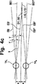
図4は、図3に示した等速ジョイントのボールペアにおけるジオメトリ関係を
a)横断面図
b)トラック平面の縦断面図
c)ボールペアの縦断面図で
示しており、
図5は、第1の構成における本発明による等速ジョイントの第2のトラックの長手方向軸線およびトラック中心線を
a)ジョイント外側部分に関して
b)ジョイント内側部分に関して
示す概略図であり、
図6は、第2の構成における本発明による等速ジョイントの第2のトラックの長手方向軸線およびトラック中心線を
a)ジョイント外側部分に関して
b)ジョイント内側部分に関して
示す概略図である。
FIG. 1 shows a constant velocity joint according to the first solving means of the present invention. A) transverse sectional view b) longitudinal sectional view along the AA sectional line in FIG. 1a c) along the BB sectional line in FIG. 1a Is shown in a longitudinal section,
FIG. 2 shows a constant velocity joint according to the second solution of the present invention. A) transverse sectional view b) longitudinal sectional view along the AA sectional line in FIG. 2a c) along the BB sectional line in FIG. 2a Is shown in a longitudinal section,
3 shows a constant velocity joint according to the third solving means of the present invention, a) a transverse sectional view b) a longitudinal sectional view along the AA sectional line of FIG.
FIG. 4 shows the geometric relationship in the ball pair of the constant velocity joint shown in FIG. 3 a) transverse section b) longitudinal section of the track plane c) longitudinal section of the ball pair,
FIG. 5 is a schematic diagram showing the second track longitudinal axis and track centerline of the constant velocity joint according to the invention in the first configuration a) with respect to the joint outer part, b) with respect to the joint inner part,
FIG. 6 is a schematic diagram showing the second track longitudinal axis and track centerline of a constant velocity joint according to the invention in a second configuration a) with respect to the joint outer part b) with respect to the joint inner part.
以下に、図1a、図1bおよび図1cを一緒に説明する。ジョイント11はジョイント外側部分12と、ジョイント内側部分13と、6個のトルク伝達ボール14と、ボールケージ15とを有している。ボールケージ15は、ジョイント外側部分12内に案内されている球面状のケージ外面16と、ジョイント内側部分13内に案内されている球面状のケージ内面17とを有している。この場合、この第2のコンタクトは必ずしも必要ではない。ボール14はボールケージ15に設けられた、周方向に分配された複数のケージ窓18内でジョイント中心平面EMに保持されている。ジョイント外側部分12には、長手方向軸線L12が規定されており、ジョイント内側部分13には、長手方向軸線L13が規定されている。長手方向軸線L12,L13とジョイント中心平面EMとの交点はジョイント中心点Mを形成している。ジョイント外側部分12は底部19と開口20とを有しており、底部19は、たとえば接続ジャーナルへ移行していてよく、開口20内には、ジョイント内側部分13に結合可能なジャーナルが差込み可能である。このためには、ジョイント内側部分13が差込み開口21を有している。さらに、底部19の位置は「接続側」へ向かう軸方向を規定し、開口20の位置は「開口側」へ向かう軸方向を規定している。このような規定はジョイント内側部分13に関しても使用されるが、ただしこの場合、ジョイント内側部分13へのシャフトの実際の接続は考えられていない。
In the following, FIGS. 1a, 1b and 1c are described together. The joint 11 includes a joint
中心平面EMを起点として、ジョイント外側部分12に対するジョイント内側部分13の最大屈曲角度βmaxに関しては、両方向にボール接触角度βmax/2が書き込まれている。全周にわたって、第1のボール141を備えた第1のトラックペア221,231と、第2のボール142を備えた第2のトラックペア222,232とが交互に設けられている。第1のトラックペア221,231の形状はA−A線に沿った断面図から明らかとなり、第2のトラックペア222,232の形状はB−B線に沿った断面図から明らかとなる。第1のボール141はジョイント外側部分12では第1の外側のボールトラック221と接触していて、かつジョイント内側部分13では第1の内側のボールトラック231と接触している。これらのトラックの中心線M221,M231はUFトラックの型式に形成されていて、それぞれ円弧と、接線方向に続いた直線とから構成されている。図示の真っ直ぐに伸長された位置では、第1の外側のボールトラック221および第1の内側のボールトラック231との接触点における第1のボール141に対する接線T22´1,T23´1が、開放側へ向かって開いた開放角度α1を形成している。第2のボール142はジョイント外側部分12に設けられた外側のボールトラック222と、ジョイント内側部分13に設けられた内側のボールトラック232とに案内されている。第2のボール142はボールトラックのトラックベースに接触した状態で図示されているが、しかしこのような接触は必ずしも与えられている必要はない。図示の真っ直ぐに伸長された位置では、ボールトラック222,232との接触点における第2のボール142に対する接線T22´2,T23´2が、接続側へ向かって開いた開放角度α2を形成している。ボールトラック22,23を説明するためには、さらにボールトラックの中心線222,M232が参照される。中心平面EMには、中心線222,M232に対する接線T222,T232が書き込まれており、これらの接線T222,T232は前で挙げた接線T22´2,T23´2に対して平行に位置している。これらの接線T222,T232の間の角度α2は4〜32゜である。
With respect to the maximum bending angle β max of the joint
図面から判るように、各トラックペアの中心線M22,M23は当該ジョイントを通る半径方向平面R1,R2に位置しており、これらの半径方向平面Rは互いに等しい角度間隔を有しており、それぞれ1つのボール14がボールケージ15に設けられたそれぞれ1つのケージ窓18によって収容される。
As can be seen from the drawing, the center lines M22 and M23 of each track pair are located in radial planes R 1 and R 2 passing through the joint, and these radial planes R have an equal angular interval. Each
以下に、図2a、図2bおよび図2cを一緒に説明する。この場合、図1に示した構成に対して変えられた構成のジョイント11が示されている。ただし、同一の構成部分は図1a〜図1cの実施例の場合と同じ符号で示されている。本発明のこの第2の構成のジョイント11は、当該ジョイントを通る半径方向平面Rに対してペアになって対称的に配置されたトラック平面BE,BE*に位置する外側および内側のボールトラック22,23を有している。図2bには、A−A線に沿って折り曲げられて断面された断面図が示されている。この断面は第1にトラック平面BEと、第1のボール141を有する第1のトラックペア221,231とを貫いて延びており、第2に2つのトラックペアの間の1つの半径方向平面を貫いて延びている。図2cには、B−B線に沿って折り曲げられて断面された断面図が示されている。この断面は第1にトラック平面BE*と、第2のボールトラック222,232を有する第2のトラックペアとを貫いて延びており、第2に2つのトラックペアの間の1つの半径方向平面を貫いて延びている。全周にわたって、それぞれ1つの第1のトラックペア221,231と第2のトラックペア222,232とを有しかつ1つの共通のケージ窓18内に保持されているトラックペアのペアが認められる。トラックペアのこれらのペアのピッチ角度は、トラックペアの同一のペアに所属していない2つの隣接したトラックペアの間よりも小さく形成されている。第1のトラックペアと第2のトラックペアとは、図示の構成では全周にわたって交互に配置されている。
In the following, FIGS. 2a, 2b and 2c are described together. In this case, the joint 11 having a configuration changed from the configuration shown in FIG. 1 is shown. However, the same components are denoted by the same reference numerals as in the embodiment of FIGS. 1a to 1c. The joint 11 of this second configuration of the invention comprises an outer and an inner ball track 22 located in track planes BE, BE * symmetrically arranged in pairs with respect to a radial plane R passing through the joint. , 23. FIG. 2b shows a cross-sectional view that is bent along the line AA. This section extends first through the track plane BE and the first track pair 22 1 , 23 1 with the
図2bから判るように、第1のボール141は外側のトラック221と内側のトラック231とから成る第1のトラックペア内に案内されている。これらのトラックはUFジョイント(アンダカットフリージョイント)のトラック型式で形成されている。すなわち、これらのトラックペアの中心線M22,M23は曲率半径を有する円弧と、これに続いた接線方向の直線とから構成されている。トラック内のボールに対する接線T22´1,T23´1は、ジョイント外側部分12の開口側に向かって開いた第1の開放角度α1を形成している。
As can be seen from FIG. 2 b, the
図2cには、第2のボール142が図示されている。この第2のボール142は第2の外側のボールトラック222と第2の内側のボールトラック232とに保持されている。第2のボール142に対する接線T22´2,T23´2は互いに、ジョイント外側部分12の接続側に向かって開いた開放角度α2を形成している。さらにトラック経過に関しては、中心線M222,M232が参照される。ジョイント中心平面EMでは、中心線M222,M232に対する接線T222,T232が、既に挙げた角度α2で互いに交差している。
Figure 2c is a
トラック平面BE,BE*は長手方向軸線に対して極めて小さな間隔を置いて平行軸線PE,PE*を含んでおり、これによってこれらの平行軸線PE,PE*はトラック平面BEと、相応する半径方向平面R1,R2に対して直角に位置する基準平面EX1,EX2との間の交線を形成する。平行軸線PE,PE*には、トラック中心点ME,ME*がジョイント中心点Mに対して極めて短い間隔を置いて位置している。それぞれ4つのトラックペアが3つまたは4つの半径方向平面Rに対して対称的に、互いに等しいピッチ角度で配置されると、12個または16個のトラックペア22,23と、相応して12個または16個のボール14とを備えたジョイントが得られる。図2aに示したように、図2bおよび図2cに図示された中心点ME1,ME1*はジョイント中心点ではなく、それぞれトラック平面BE1,BE1*におけるトラック曲線中心点である。
The track planes BE, BE * contain parallel axes PE, PE * with a very small spacing with respect to the longitudinal axis, so that these parallel axes PE, PE * correspond to the track plane BE and the corresponding radial direction. An intersection line is formed between the reference planes EX1 and EX2 positioned at right angles to the planes R1 and R2. On the parallel axes PE and PE * , the track center points ME and ME * are located at a very short distance from the joint center point M. If four track pairs are arranged symmetrically with respect to three or four radial planes R and at equal pitch angles, 12 or 16 track pairs 22, 23 and 12 correspondingly Or a joint with 16
以下に、図3aおよび図3bを一緒に説明する。図3aは原理的には図2aに相当しているが、しかし断面線A−Aはこの場合、基準平面EX1に対して平行にトラックペアの1つのペアのボールを貫いて延びるように設置されている。図3bには、外側のボールトラックのための第1の基準平面EBが示されている。この第1の基準平面EBは上記基準平面EX1に直角に位置していて、ジョイント中心点Mを通る半径方向斜線(Radialstrahl)RSを含んでいる。この基準平面EBは長手方向軸線L12,L13を通る半径方向平面Rと共に傾斜角度γを形成している。基準平面EBに対して平行にトラック平面BEおよびBE*が位置しており、これらのトラック平面BEおよびBE*には、1つのトラックペアの外側のボールトラックの中心線が延びている。さらに図3bには、内側のボールトラックのための第1の基準平面EB´が示されている。この第1の基準平面EB´はやはり上記基準平面EX1に直角に位置していて、ジョイント中心点Mを通る半径方向射線RSを含んでいる。この基準平面EB´は長手方向軸線L12,L13を通る半径方向平面Rと共に傾斜角度γ´を形成しており、この傾斜角度γ´は前記傾斜角度γと等しい大きさでかつ前記傾斜角度γとは逆向きに形成されている。基準平面EB´に対して平行にトラック平面BE´,BE*´が位置しており、これらのトラック平面BE´,BE*´には1つのトラックペアの内側のボールトラックの中心線が延びている。各トラックペアの中心線はジョイント中心平面EMで互いに交差している。 In the following, FIGS. 3a and 3b will be described together. FIG. 3a corresponds in principle to FIG. 2a, but the section line AA is in this case arranged to run through one pair of balls of the track pair parallel to the reference plane EX1. ing. FIG. 3b shows a first reference plane EB for the outer ball track. The first reference plane EB is positioned at right angles to the reference plane EX1 and includes a radial diagonal line (Radialstrahl) RS passing through the joint center point M. This reference plane EB forms an inclination angle γ with a radial plane R passing through the longitudinal axes L12, L13. Track planes BE and BE * are positioned in parallel to the reference plane EB, and the center line of the outer ball track of one track pair extends in these track planes BE and BE * . Furthermore, FIG. 3b shows a first reference plane EB ′ for the inner ball track. This first reference plane EB ′ is also positioned perpendicular to the reference plane EX1 and includes a radial ray RS passing through the joint center point M. The reference plane EB ′ forms an inclination angle γ ′ together with the radial plane R passing through the longitudinal axes L12 and L13, and the inclination angle γ ′ is equal to the inclination angle γ and the inclination angle γ. Are formed in the opposite direction. Track planes BE ′ and BE * ′ are located in parallel to the reference plane EB ′, and the center line of the ball track inside one track pair extends on these track planes BE ′ and BE * ′. Yes. The center lines of each track pair intersect each other at the joint center plane EM.
以下に、図4a、図4bおよび図4cを一緒に説明する。図4aには、図3に類似した、ジョイント中心平面に位置する、4つのボールペア141,142から成るボール配置の横断面図が示されている。1つのボールペアのボール141,142と、その間に位置する半径方向平面R1との間のピッチ角度はφ0もしくはφ0´である。ボールトラックは基準平面EX1から、転がり円半径PCRをφ0のコサインで乗算した値に相当する間隔を有している。上記半径方向平面R1からの1つのボールペアのボールの直角の間隔は、それぞれ「a」で示されている。書き込まれたトラック平面BE1,BE1 *はジョイント中心平面を通る、外側のボールトラックのトラック平面BE,BE*の通過部および内側のボールトラックのトラック平面BE´,BE*´の通過部を表している。
In the following, FIGS. 4a, 4b and 4c are described together. FIG. 4a shows a cross-sectional view of a ball arrangement consisting of four ball pairs 14 1 , 14 2 located in the joint center plane, similar to FIG. The pitch angle between the
図4bには、トラック平面BE1,BE1 *のいずれか一方のトラック平面の断面図で、第2のトラックペアのトラック中心線に対する接線T22,T23の間のトラック開放角度が「α2」で示されている。この場合、書き込まれた角度脚線はトラックのトラック基本線に対する接線T22´,T23´を成している。したがって、α2/2は開放角度の1/2もしくはトラック傾斜角度に相当している。 FIG. 4B is a cross-sectional view of one of the track planes BE 1 and BE 1 * , and the track opening angle between the tangents T22 and T23 with respect to the track center line of the second track pair is “α 2 ”. It is shown in In this case, the written angular leg lines form tangents T22 ′ and T23 ′ with respect to the track basic line of the track. Thus, alpha 2/2 is equivalent to 1/2 or track inclination angle of the opening angle.
図4cには、外側のトラック平面EB,EB*と内側のトラック平面EB´,EB*´とを備えたボールペア141,142が示されている。図4bに示した、トラック接線の貫徹点D1,D2が同じく書き込まれている。
FIG. 4 c shows a
以下の導関数は、上記トラック接線T22,T23が長手方向軸線L12,L13で半径方向平面Rを貫徹する、つまり貫徹D1,D2が長手方向軸線L12,L13上に位置する理想的事例に該当する。 The following derivatives correspond to the ideal case where the track tangents T22, T23 penetrate the radial plane R at the longitudinal axes L12, L13, ie the penetrations D1, D2 are located on the longitudinal axes L12, L13. .
以下の関係が成り立つ:
(1) a=PCR・sinφ0´
(2)
The following relationship holds:
(1) a = PCR · sinφ 0 ′
(2)

小さな角度α2/2およびγに関しては、近似が成立する; For small angles α2 / 2 and γ, an approximation holds;
図5aには、図1〜図3のうちの1つに示した外側のボールトラック22の、トラック基本線に対して平行に延びるトラック中心線M22が図示されている。外側部分における1つのトラックの中心線M22は、第1の軸方向のオフセットO1aと半径方向のオフセットO1rとを有する中心点M1を中心とした第1の半径R1と、第2の軸方向のオフセットO2aと第2の半径方向のオフセットO2rとを有する第2の半径R2とから構成されている。移行部は反転点W22により規定されている。第2の半径R2には、長手方向軸線L12もしくは平行軸線PE,PE*に対して平行な直線G3が接線方向に続いている。中心平面EMには、中心線M22に対する接線T22が書き込まれており、この接線T22は長手方向軸線L12もしくは平行軸線PE,PE*に角度α/2で交差している。長手方向軸線L12もしくは平行軸線PE,PE*には、基準半径RBの基準中心点MB,MBEで接線T22に対する垂直線が交差している。トラック中心点M,MEを中心にして別の基準半径RZが描かれている。図面で見て中心平面EMから左側に接続側19へ向かって、中心線M22は基準半径RBの内側でかつ基準半径RZの外側に延びている。中心平面EMから右側に開口側20へ向かって、中心線M22は大体において基準半径RBの外側に延びている。トラック中心点M,MEに関するボールトラックに沿ったボール軌道上での1つのボールの半径方向のボール運動は「e」で示されている。このことはケージ窓の範囲におけるボールケージの最小厚さに相当している。ただし、片当たり(Kantentraeger)を回避するための安全マージン(Sicherheitszuschlag)が必要となる。
FIG. 5a shows a track center line M22 extending parallel to the track base line of the outer ball track 22 shown in one of FIGS. A center line M22 of one track in the outer portion includes a first radius R1 centered on a center point M1 having a first axial offset O1a and a radial offset O1r, and a second axial offset. And a second radius R2 having a second radial offset O2r. The transition portion is defined by the inversion point W22. In the second radius R2, a straight line G3 parallel to the longitudinal axis L12 or the parallel axes PE, PE * continues in the tangential direction. In the center plane EM, a tangent line T22 with respect to the center line M22 is written, and this tangent line T22 intersects the longitudinal axis L12 or the parallel axes PE, PE * at an angle α / 2. The longitudinal axis L12 or the parallel axes PE and PE * intersect with a perpendicular line to the tangent line T22 at the reference center points MB and MBE of the reference radius RB. Another reference radius RZ is drawn around the track center points M and ME. In the drawing, the center line M22 extends from the center plane EM to the
図5bには、図1〜図3のうちの1つに示した、所属の内側のボールトラック23の、トラック基本線に対して平行に延びるトラック中心線M23が示されている。内側部分13内のボールトラック23の中心線M23は中心点M1´を中心とした第1の半径R1´と、中心点M2´を中心とした第2の半径R2´とから構成されている。移行部は反転点W23により規定されている。第2の半径R2´には、軸線L13,PE,PE*,PE´,PE*´に対して平行な直線G3´が続いている。この場合、中心点M1´は軸方向のオフセットO1a´と、半径方向のオフセットO1r´とを有しており、中心点M2´は軸方向のオフセットO2a´と、半径方向のオフセットO2r´とを有している。中心平面EMには、中心線M23に対する接線T23が書き込まれており、この接線T23は長手方向軸線L13,PE,PE*,PE´,PE*´に角度α/2で交差している。長手方向軸線L13,PE,PE*,PE´,PE*´には、基準半径RB´の基準中心点MB´,MBE´において接線T23に対する垂直線が交差している。トラック中心点M,MEを中心にして別の基準半径RZ´が描かれている。図面で見て中心平面EMから右側に開口側20へ向かって中心線M23は基準半径RB´の内側でかつ基準半径RZ´の外側に延びている。中心平面EMから左側に接続側19へ向かって、中心線M23は少なくとも大体において基準半径RB´の外側に延びている。トラック中心点M,MEに関するボールトラックに沿ったボール軌道における1つのボールの半径方向のボール運動は、「e」で示されている。図5a,図5bに示した両中心線M22,M23はジョイント中心平面EMで角度αを成して互いに交差していて、このジョイント中心平面EMに対して鏡像対称的に延びている。
FIG. 5b shows a track center line M23 of the associated inner ball track 23 shown in one of FIGS. 1 to 3 extending parallel to the track base line. The center line M23 of the ball track 23 in the
図6aには、外側のボールトラック22の、トラック基本線に対して平行に延びるトラック中心線M22の変化実施例が示されている。外側部分における1つのボールトラックの中心線M22は第1の軸方向のオフセットO1aと半径方向のオフセットO1rとを有する中心点M1を中心とした第1の半径R1と、第2の軸方向のオフセットO2aと第2の半径方向のオフセットO2rとを有する第2の半径R2と、第3の半径R3とから構成されている。この第3の半径R3は第2の半径R2とは逆向きで第1の半径R1に続いている。第3の半径R3は第1の半径R1よりも小さく形成されていて、同じ方向に湾曲させられており、この場合、この第3の半径R3の中心点M3の位置は詳細には設定されていない。第1の半径R1と第2の半径R2との間の移行部は反転点W22により示されている。第2の半径R2には、軸線L12,PE,PE*に対して平行な直線G3が接線方向で続いている。中心平面EMには、中心線M22に対する接線T22が書き込まれており、この接線T22は長手方向軸線L12,PE,PE*に角度α/2で交差している。長手方向軸線L12,PE,PE*には、基準半径RBの基準中心点MB,MBEにおいて接線T22に対する垂直線が交差している。トラック中心点M,MEを中心にして、別の基準半径RZが描かれている。図面で見て中心平面EMから左側に接続側19へ向かって中心線M22は基準半径RBの内側でかつ基準半径RZの外側に延びている。中心平面EMから右側に開口側20へ向かって、中心線M22は大体において基準半径RBの外側に延びている。トラック中心点M,MEに関するボールトラックに沿ったボール軌道における1つのボールの半径方向のボール運動は、「e」で示されている。このことは、ケージ窓の範囲におけるボールケージの最小厚さに相当している。ただし、片当たりを回避するために安全マージンが必要となる。
FIG. 6a shows a variant embodiment of the track center line M22 of the outer ball track 22 extending parallel to the track base line. A center line M22 of one ball track in the outer portion includes a first radius R1 centered at a center point M1 having a first axial offset O1a and a radial offset O1r, and a second axial offset. It comprises a second radius R2 having O2a and a second radial offset O2r, and a third radius R3. The third radius R3 follows the first radius R1 in the opposite direction to the second radius R2. The third radius R3 is smaller than the first radius R1 and is curved in the same direction. In this case, the position of the center point M3 of the third radius R3 is set in detail. Absent. The transition between the first radius R1 and the second radius R2 is indicated by the inversion point W22. A straight line G3 parallel to the axes L12, PE, and PE * continues in the tangential direction to the second radius R2. In the center plane EM, a tangent line T22 to the center line M22 is written, and this tangent line T22 intersects the longitudinal axis lines L12, PE, PE * at an angle α / 2. The longitudinal axis L12, PE, PE * intersects a perpendicular line to the tangent line T22 at the reference center points MB, MBE of the reference radius RB. Another reference radius RZ is drawn around the track center points M and ME. The center line M22 extends from the center plane EM to the
図6bには、所属の内側のボールトラック23の、トラック基本線に対して平行に延びるトラック中心線M23の変化実施例が図示されている。ジョイント内側部分13内の1つのボールトラック23の中心線M23は、中心点M1´を中心とした第1の半径R1´と、中心点M2´を中心とした第2の半径R2´と、第2の半径R2´とは逆向きで第1の半径R1´に続いた第3の半径R3´とから構成されている。第3の半径R3´は第1の半径R1´よりも小さく形成されていて、かつ同じ方向に湾曲させられている。第2の半径R2´には、長手方向軸線L13,PE,PE*,PE´,PE*´に対して平行な直線G3´が続いている。この場合、中心点M1´は軸方向のオフセットO1a´と半径方向のオフセットO1r´とを有しており、中心点M2´は軸方向のオフセットO2a´と半径方向のオフセットO2r´とを有している。中心点M3´の位置は詳細には設定されていない。中心平面EMには、中心線M23に対する接線T23が書き込まれており、この接線T23は長手方向軸線L13,PE,PE*,PE´,PE*´に角度α/2を成して交差している。長手方向軸線L13,PE,PE*,PE´,PE*´には、基準半径RB´の基準中心点MB´,MBE´において接線T23に対する垂直線が交差している。トラック中心点M,MEを中心にして別の基準半径RZ´が描かれている。図面で見て中心平面EMから右側に開口側20へ向かって、中心線M23は基準半径RB´の内側でかつ基準半径RZ´の外側に延びている。中心平面EMから左側に接続側19へ向かって、中心線M23は大体において基準半径RB´の外側に延びている。トラック中心点M,MEに関するボールトラックに沿ったボール軌道におけるボールの半径方向のボール運動は「e」で示されている。図6aおよび図6bに示した両中心線M23,M23はジョイント中心平面EMで角度αを成して互いに交差していて、この中心平面に対して鏡像対称的に延びている。
FIG. 6b shows a variation of the track center line M23 of the associated inner ball track 23 extending parallel to the track base line. The center line M23 of one ball track 23 in the joint
11 ジョイント
12 ジョイント外側部分
13 ジョイント内側部分
14 ボール
15 ケージ
16 ケージ外面
17 ケージ内面
18 ケージ窓
19 底部
20 開口
21 差込み開口
22 外側のボールトラック
23 内側のボールトラック
24 トラック底部(外側のボールトラック)
25 トラック底部(内側のボールトラック)
26 トラック側縁
27 トラック側縁
EM ジョイント中心平面
L12 外側部分の長手方向軸線
L13 内側部分の長手方向軸線
M22 ボールトラック22の中心線
M23 ボールトラック23の中心線
DESCRIPTION OF
25 Track bottom (inner ball track)
26 Track side edge 27 Track side edge EM Joint center plane L12 Longitudinal axis of outer part L13 Longitudinal axis of inner part M22 Center line of ball track 22 M23 Center line of ball track 23
Claims (3)
長手方向軸線(L12)と、軸方向で互いに逆向きに位置する接続側および開口側とを有するジョイント外側部分(12)が設けられており、該ジョイント外側部分(12)が外側のボールトラック(22)を有しており、
長手方向軸線(L13)と、ジョイント外側部分(12)の開口側に向けられたシャフトのための接続手段とを有するジョイント内側部分(13)が設けられており、該ジョイント内側部分(13)が内側のボールトラック(23)を有しており、
外側のボールトラック(22)と内側のボールトラック(23)とが、互いに一緒になってトラックペア(22,23)を形成しており、
該トラックペアがそれぞれ1つのトルク伝達ボール(14)を収容しており、
ジョイント外側部分(12)とジョイント内側部分(13)との間に環状のボールケージ(15)が嵌め込まれており、該ボールケージ(15)が、周方向で分配された複数のケージ窓(18)を有しており、該ケージ窓(18)がそれぞれ少なくとも1つのトルク伝達ボール(14)を収容しており、
ボール(14)の中心点がボールケージ(15)によってジョイント中心平面(EM)に保持されていて、ジョイント屈曲時に両長手方向軸線(L12,L13)の間の角度の二等分線の平面へ案内されるようになっており、
トラックペアのボールトラック(22,23)の中心線(M22,M23)が、当該ジョイントを通る半径方向平面(R)に位置しており、
トラックペアの第1の部分に関しては、両長手方向軸線(L12,L13)が互いに合致する当該ジョイントの真っ直ぐに伸長された状態でジョイント中心平面(EM)におけるボールトラック(221,231)の中心線(M221,M231)に対する接線(T221,T231)に対して平行に延びるトラック基本線に対する接線(T22´1,T23´1)の間の開放角(α1)が接続側から開口側に向かって開いており、
トラックペアの第2の部分に関しては、両長手方向軸線(L12,L13)が互いに合致する当該ジョイントの真っ直ぐに伸長された状態でジョイント中心平面(EM)におけるボールトラック(222,232)の中心線(M222,M232)に対する接線(T222,T232)に対して平行に延びるトラック基本線に対する接線(T22´2,T23´2)の間の開放角(α2)が開口側から接続側に向かって開いており、
第2のトラックペアの中心線に関して:
ジョイント外側部分(12)でボールトラック(222)の中心線(M222)が、ジョイント中心平面(EM)から接続側までの範囲でそれぞれ、ジョイント中心平面(EM)内のボールトラック(222)の中心線(M222)に対する接線(T222)に対する垂直線と長手方向軸線(L12)との交点に位置する半径中心点(MB)を有する基準半径(RB)から半径方向内側へ向かって離れており、
ジョイント内側部分(13)でボールトラック(232)の中心線(M232)が、ジョイント中心平面(EM)から開口側までの範囲でそれぞれ、ジョイント中心平面(EM)内のボールトラック(232)の中心線(M232)に対する接線(T232)に対する垂直線と長手方向軸線(L13)との交点に位置する半径中心点(MB´)を有する基準半径(RB´)から半径方向内側へ向かって離れており、
ジョイント外側部分(12)でボールトラック(222)の中心線(M222)が、ジョイント中心平面(EM)から開口側までの範囲で前記基準半径(RB)を半径方向外側へ向かって越えて移動しており、
ジョイント内側部分(13)でボールトラック(232)の中心線(M232)が、ジョイント中心平面(EM)から接続側までの範囲で前記基準半径(RB´)を半径方向外側へ向かって越えて移動している、
を有していることを特徴とする、カウンタトラックジョイントの形の等速ジョイント。In constant velocity joints in the form of counter track joints, the following features:
A joint outer portion (12) is provided having a longitudinal axis (L12) and a connecting side and an opening side that are opposite to each other in the axial direction, the joint outer portion (12) being an outer ball track ( 22)
A joint inner part (13) is provided having a longitudinal axis (L13) and a connecting means for the shaft directed towards the opening side of the joint outer part (12), the joint inner part (13) being Has an inner ball track (23),
The outer ball track (22) and the inner ball track (23) are joined together to form a track pair (22, 23),
Each of the track pairs contains one torque transmitting ball (14);
An annular ball cage (15) is fitted between the joint outer part (12) and the joint inner part (13), and the ball cage (15) is arranged in a plurality of cage windows (18) distributed in the circumferential direction. And each of the cage windows (18) contains at least one torque transmitting ball (14),
The center point of the ball (14) is held in the joint center plane (EM) by the ball cage (15) and into the plane of the bisector of the angle between the two longitudinal axes (L12, L13) when the joint is bent. It has come to be guided,
The center line (M22, M23) of the ball track (22, 23) of the track pair is located in a radial plane (R) passing through the joint,
With respect to the first part of the track pair, the ball tracks (22 1 , 23 1 ) in the joint center plane (EM) with both longitudinal axes (L12, L13) extending straight of the joints that coincide with each other. center line (M22 1, M23 1) tangent to (T22 1, T23 1) tangent to the track base lines which extend parallel to the (T22' 1, T23' 1) opening angle (alpha 1) is the side connected between Open toward the opening side from
With respect to the second part of the track pair, the ball tracks (22 2 , 23 2 ) in the joint center plane (EM) with both longitudinal axes (L12, L13) straightened out of the joints that coincide with each other. center line tangent to (M22 2, M23 2) ( T22 2, T23 2) tangent to the track base lines which extend parallel to the (T22' 2, T23' 2) opening angle (alpha 2) is the open side between the Open toward the connection side,
Regarding the centerline of the second track pair:
Center line of the ball tracks in the outer joint part (12) (22 2) ( M22 2) are each in the range from the joint center plane (EM) to the connection side, the ball tracks in the joint center plane (EM) (22 2 ) From the reference radius (RB) having the radial center point (MB) located at the intersection of the vertical line with respect to the tangent line (T22 2 ) to the center line (M22 2 ) and the longitudinal axis (L12), inward in the radial direction. Away
Center line of the ball tracks (23 2) in the inner joint part (13) (M23 2) are each in the range from the joint center plane (EM) to the aperture end, the ball tracks in the joint center plane (EM) (23 2 ) From the reference radius (RB ′) having the radial center point (MB ′) located at the intersection of the vertical line with respect to the tangent line (T23 2 ) to the center line (M23 2 ) and the longitudinal axis (L13) inward in the radial direction Away
In the joint outer portion (12), the center line (M22 2 ) of the ball track (22 2 ) extends beyond the reference radius (RB) radially outward in the range from the joint center plane (EM) to the opening side. Is moving,
In the joint inner portion (13), the center line (M23 2 ) of the ball track (23 2 ) exceeds the reference radius (RB ′) radially outward in the range from the joint center plane (EM) to the connection side. Moving
Constant velocity joint in the form of a counter track joint, characterized in that it has
長手方向軸線(L12)と、軸方向で互いに逆向きに位置する接続側および開口側とを有するジョイント外側部分(12)が設けられており、該ジョイント外側部分(12)が外側のボールトラック(221,222)を有しており、
長手方向軸線(L13)と、ジョイント外側部分(12)の開口側(20)に向けられたシャフトのための接続手段とを有するジョイント内側部分(13)が設けられており、該ジョイント内側部分(13)が内側のボールトラック(231,232)を有しており、
外側のボールトラック(221,222)と内側のボールトラック(231,232)とが、互いに一緒にトラックペア(221,231;222,232)を形成しており、
該トラックペアがそれぞれ1つのトルク伝達ボール(14)を収容しており、
ジョイント外側部分(12)とジョイント内側部分(13)との間に環状のボールケージ(15)が嵌め込まれており、該ボールケージ(15)が、周方向で分配された複数のケージ窓(18)を有しており、該ケージ窓(18)がそれぞれ少なくとも1つのトルク伝達ボール(14)を収容しており、
ボール(14)の中心点がボールケージ(15)によってジョイント中心平面(EM)に保持されていて、ジョイント屈曲時に両長手方向軸線(L12,L13)の間の角度の二等分線の平面へ案内されるようになっており、
トラックペアのボールトラック(221,231;222,232)の中心線(M22,M23)が、互いにほぼ平行でかつ長手方向軸線(L12,L13)を通る半径方向平面(R1,R2)に対して対称的に延びるトラック平面(BE,BE*)のペアに位置しており、
トラックペアの第1の部分に関しては、両長手方向軸線(L12,L13)が互いに合致する当該ジョイントの真っ直ぐに伸長された状態でジョイント中心平面(EM)におけるボールトラック(221,231)の中心線(M221,M231)に対する接線(T221,T231)に対して平行に延びるトラック基本線に対する接線(T22´1,T23´1)の間の開放角(α1)が接続側から開口側に向かって開いており、
トラックペアの第2の部分に関しては、両長手方向軸線(L12,L13)が互いに合致する当該ジョイントの真っ直ぐに伸長された状態でジョイント中心平面(EM)におけるボールトラック(222,232)の中心線(M222,M232)に対する接線(T222,T232)に対して平行に延びるトラック基本線に対する接線(T22´2,T23´2)の間の開放角(α2)が開口側から接続側に向かって開いており、
第2のトラックペア(222,232)の中心線に関して:
ジョイント外側部分(12)でボールトラック(222)の中心線(M222)が、ジョイント中心平面(EM)から接続側までの範囲でそれぞれ、ジョイント中心平面(EM)内のボールトラック(222)の中心線(M222)に対する接線(T222)に対する垂直線と、トラック平面(BE,BE*)を通る長手方向軸線(L12)に対する平行軸線(PE,PE*)との交点に位置する半径中心点(MBE)を有する基準半径(RB)から半径方向内側へ向かって離れており、
ジョイント内側部分(13)でボールトラック(232)の中心線(M232)が、ジョイント中心平面(EM)から開口側までの範囲でそれぞれ、ジョイント中心平面(EM)内のボールトラック(232)の中心線(M232)に対する接線(T232)に対する垂直線と、トラック平面(BE,BE*)を通る長手方向軸線(L13)に対する平行軸線(PE,PE*)との交点に位置する半径中心点(MBE´)を有する基準半径(RB´)から半径方向内側へ向かって離れており、
ジョイント外側部分(12)でボールトラック(222)の中心線(M222)が、ジョイント中心平面(EM)から開口側までの範囲で前記基準半径(RB)を半径方向外側へ向かって越えて移動しており、
ジョイント内側部分(13)でボールトラック(232)の中心線(M232)が、ジョイント中心平面(EM)から接続側までの範囲で前記基準半径(RB´)を半径方向外側へ向かって越えて移動している、
を有していることを特徴とする、固定型ジョイントの形の等速ジョイント。For constant velocity joints in the form of fixed joints, the following features:
A joint outer portion (12) is provided having a longitudinal axis (L12) and a connecting side and an opening side that are opposite to each other in the axial direction, the joint outer portion (12) being an outer ball track ( 22 1 , 22 2 )
A joint inner part (13) is provided having a longitudinal axis (L13) and connecting means for a shaft directed to the open side (20) of the joint outer part (12), the inner part of the joint ( 13) has inner ball tracks (23 1 , 23 2 ),
The outer ball track (22 1 , 22 2 ) and the inner ball track (23 1 , 23 2 ) together form a track pair (22 1 , 23 1 ; 22 2 , 23 2 ),
Each of the track pairs contains one torque transmitting ball (14);
An annular ball cage (15) is fitted between the joint outer part (12) and the joint inner part (13), and the ball cage (15) is arranged in a plurality of cage windows (18) distributed in the circumferential direction. And each of the cage windows (18) contains at least one torque transmitting ball (14),
The center point of the ball (14) is held in the joint center plane (EM) by the ball cage (15) and into the plane of the bisector of the angle between the two longitudinal axes (L12, L13) when the joint is bent. It has come to be guided,
Radial planes (R1, R2) in which the center lines (M22, M23) of the ball tracks (22 1 , 23 1 ; 22 2 , 23 2 ) of the track pair are substantially parallel to each other and pass through the longitudinal axes (L12, L13). ) Located in a pair of track planes (BE, BE * ) extending symmetrically with respect to
With respect to the first part of the track pair, the ball tracks (22 1 , 23 1 ) in the joint center plane (EM) with both longitudinal axes (L12, L13) extending straight of the joints that coincide with each other. center line (M22 1, M23 1) tangent to (T22 1, T23 1) tangent to the track base lines which extend parallel to the (T22' 1, T23' 1) opening angle (alpha 1) is the side connected between Open toward the opening side from
With respect to the second part of the track pair, the ball tracks (22 2 , 23 2 ) in the joint center plane (EM) with both longitudinal axes (L12, L13) straightened out of the joints that coincide with each other. center line tangent to (M22 2, M23 2) ( T22 2, T23 2) tangent to the track base lines which extend parallel to the (T22' 2, T23' 2) opening angle (alpha 2) is the open side between the Open toward the connection side,
Regarding the centerline of the second track pair (22 2 , 23 2 ):
Center line of the ball tracks in the outer joint part (12) (22 2) ( M22 2) are each in the range from the joint center plane (EM) to the connection side, the ball tracks in the joint center plane (EM) (22 2 ) At the intersection of a perpendicular line to the tangent line (T22 2 ) to the center line (M22 2 ) and a parallel axis line (PE, PE * ) to the longitudinal axis (L12) passing through the track plane (BE, BE * ). Away from a reference radius (RB) having a radial center point (MBE) radially inward;
Center line of the ball tracks (23 2) in the inner joint part (13) (M23 2) are each in the range from the joint center plane (EM) to the aperture end, the ball tracks in the joint center plane (EM) (23 2 ) At the intersection of a perpendicular line to the tangent (T23 2 ) to the center line (M23 2 ) and a parallel axis (PE, PE * ) to the longitudinal axis (L13) passing through the track plane (BE, BE * ). Away from a reference radius (RB ′) having a radius center point (MBE ′) radially inward;
In the joint outer portion (12), the center line (M22 2 ) of the ball track (22 2 ) extends beyond the reference radius (RB) radially outward in the range from the joint center plane (EM) to the opening side. Is moving,
In the joint inner portion (13), the center line (M23 2 ) of the ball track (23 2 ) exceeds the reference radius (RB ′) radially outward in the range from the joint center plane (EM) to the connection side. Moving
A constant velocity joint in the form of a fixed joint, characterized in that it has
長手方向軸線(L12)と、軸方向で互いに逆向きに位置する接続側および開口側とを有ジョイント外側部分(12)が設けられており、該ジョイント外側部分(12)が外側のボールトラック(221,222)を有しており、
長手方向軸線(L13)と、ジョイント外側部分(12)の開口側(20)に向けられたシャフトのための接続手段とを有するジョイント内側部分(13)が設けられており、該ジョイント内側部分(13)が内側のボールトラック(231,232)を有しており、
外側のボールトラック(221,222)と内側のボールトラック(231,232)とが、互いに一緒にトラックペア(221,231;222,232)を形成しており、
該トラックペアがそれぞれ1つのトルク伝達ボール(14)を収容しており、
ジョイント外側部分(12)とジョイント内側部分(13)との間に環状のボールケージ(15)が嵌め込まれており、該ボールケージ(15)が、周方向で分配された複数のケージ窓(18)を有しており、該ケージ窓(18)がそれぞれ少なくとも1つのトルク伝達ボール(14)を収容しており、
ボール(14)の中心点がボールケージ(15)によってジョイント中心平面(EM)に保持されていて、ジョイント屈曲時に両長手方向軸線(L12,L13)の間の角度の二等分線の平面へ案内されるようになっており、
ジョイント外側部分(12)における互いに隣接したボールトラック(221,222)の中心線(M221,M222)が、互いにほぼ平行でかつジョイント中心点(M)を通る半径方向射線(RS1,RS2)に対して対称的に延びる第1のトラック平面(BE,BE*)のペアに位置しており、
ジョイント内側部分(13)における互いに隣接したボールトラック(231,232)の中心線(M231,M232)が、互いに平行でかつジョイント中心点(M)を通る半径方向射線(RS1,RS2)に対して対称的に延びる第2のトラック平面(BE´,BE*´)のペアに位置しており、
第1のトラック平面(BE,BE*)と第2のトラック平面(BE´,BE*´)とが、長手方向軸線(L12,L13)を通る半径方向平面(R1,R2)と共に等しい大きさの、ただし互いに逆向きに形成された角度(γ,γ´)を形成しており、
トラックペアの第1の部分に関しては、両長手方向軸線(L12,L13)が互いに合致する当該ジョイントの真っ直ぐに伸長された状態でジョイント中心平面(EM)におけるボールトラック(221,231)の中心線(M221,M231)に対する接線(T221,T231)に対して平行に延びるトラック基本線に対する接線(T22´1,T23´1)の間の開放角(α1)が接続側から開口側に向かって開いており、
トラックペアの第2の部分に関しては、両長手方向軸線(L12,L13)が互いに合致する当該ジョイントの真っ直ぐに伸長された状態でジョイント中心平面(EM)におけるボールトラック(222,232)の中心線(M222,M232)に対する接線(T222,T232)に対して平行に延びるトラック基本線に対する接線(T22´2,T23´2)の間の開放角(α2)が開口側から接続側に向かって開いており、
第2のトラックペア(222,232)の中心線に関して:
ジョイント外側部分(12)でボールトラック(222)の中心線(M222)が、ジョイント中心平面(EM)から接続側までの範囲でそれぞれ、ジョイント中心平面(EM)内のボールトラック(222)の中心線(M222)に対する接線(T222)に対する垂直線と、トラック平面(BE,BE*)を通る基準軸線(PE,PE*)との交点に位置する半径中心点(MBE)を有する基準半径(RB)から半径方向内側へ向かって離れており、
ジョイント内側部分(13)でボールトラック(232)の中心線(M232)が、ジョイント中心平面(EM)から開口側までの範囲でそれぞれ、ジョイント中心平面(EM)内のボールトラック(232)の中心線(M232)に対する接線(T232)に対する垂直線と、トラック平面(BE´,BE*´)を通る基準軸線(PE´,PE*´)との交点に位置する半径中心点(MBE´)を有する基準半径(RB´)から半径方向内側へ向かって離れており、
ジョイント外側部分(12)でボールトラック(222)の中心線(M222)が、ジョイント中心平面(EM)から開口側までの範囲で前記基準半径(RB)を半径方向外側へ向かって越えて移動しており、
ジョイント内側部分(13)でボールトラック(232)の中心線(M232)が、ジョイント中心平面(EM)から接続側までの範囲で前記基準半径(RB´)を半径方向外側へ向かって越えて移動している、
を有していることを特徴とする、固定型ジョイントの形の等速ジョイント。In constant velocity joints in the form of fixed joints,
A joint outer portion (12) is provided with a longitudinal axis (L12) and a connection side and an opening side that are opposite to each other in the axial direction, and the joint outer portion (12) is an outer ball track ( 22 1 , 22 2 )
A joint inner part (13) is provided having a longitudinal axis (L13) and connecting means for a shaft directed to the open side (20) of the joint outer part (12), the inner part of the joint ( 13) has inner ball tracks (23 1 , 23 2 ),
The outer ball track (22 1 , 22 2 ) and the inner ball track (23 1 , 23 2 ) together form a track pair (22 1 , 23 1 ; 22 2 , 23 2 ),
Each of the track pairs contains one torque transmitting ball (14);
An annular ball cage (15) is fitted between the joint outer part (12) and the joint inner part (13), and the ball cage (15) is arranged in a plurality of cage windows (18) distributed in the circumferential direction. And each of the cage windows (18) contains at least one torque transmitting ball (14),
The center point of the ball (14) is held in the joint center plane (EM) by the ball cage (15) and into the plane of the bisector of the angle between the two longitudinal axes (L12, L13) when the joint is bent. It has come to be guided,
The center lines (M22 1 , M22 2 ) of the ball tracks (22 1 , 22 2 ) adjacent to each other in the joint outer portion (12) are substantially parallel to each other and radial rays (RS1, RS2) passing through the joint center point (M) RS2) located in a pair of first track planes (BE, BE * ) extending symmetrically with respect to
Radial rays (RS1, RS2) in which the center lines (M23 1 , M23 2 ) of the ball tracks (23 1 , 23 2 ) adjacent to each other in the joint inner part (13) are parallel to each other and pass through the joint center point (M). ) In a pair of second track planes (BE ′, BE * ′) extending symmetrically with respect to
The first track plane (BE, BE * ) and the second track plane (BE ′, BE * ′) are equal in size with radial planes (R1, R2) passing through the longitudinal axes (L12, L13). However, they form angles (γ, γ ′) formed in opposite directions,
With respect to the first part of the track pair, the ball tracks (22 1 , 23 1 ) in the joint center plane (EM) with both longitudinal axes (L12, L13) extending straight of the joints that coincide with each other. center line (M22 1, M23 1) tangent to (T22 1, T23 1) tangent to the track base lines which extend parallel to the (T22' 1, T23' 1) opening angle (alpha 1) is the side connected between Open toward the opening side from
With respect to the second part of the track pair, the ball tracks (22 2 , 23 2 ) in the joint center plane (EM) with both longitudinal axes (L12, L13) straightened out of the joints that coincide with each other. center line tangent to (M22 2, M23 2) ( T22 2, T23 2) tangent to the track base lines which extend parallel to the (T22' 2, T23' 2) opening angle (alpha 2) is the open side between the Open toward the connection side,
Regarding the centerline of the second track pair (22 2 , 23 2 ):
Center line of the ball tracks in the outer joint part (12) (22 2) ( M22 2) are each in the range from the joint center plane (EM) to the connection side, the ball tracks in the joint center plane (EM) (22 2 ) Of the radial center point (MBE) located at the intersection of the perpendicular line to the tangent line (T22 2 ) to the center line (M22 2 ) and the reference axis line (PE, PE * ) passing through the track plane (BE, BE * ). Away from a reference radius (RB) having a radially inward direction;
Center line of the ball tracks (23 2) in the inner joint part (13) (M23 2) are each in the range from the joint center plane (EM) to the aperture end, the ball tracks in the joint center plane (EM) (23 2 ) Radial center point located at the intersection of the perpendicular line to the tangent line (T23 2 ) to the center line (M23 2 ) and the reference axis line (PE ′, PE * ′) passing through the track plane (BE ′, BE * ′) Away from a reference radius (RB ′) having (MBE ′) radially inward,
In the joint outer portion (12), the center line (M22 2 ) of the ball track (22 2 ) extends beyond the reference radius (RB) radially outward in the range from the joint center plane (EM) to the opening side. Is moving,
In the joint inner portion (13), the center line (M23 2 ) of the ball track (23 2 ) exceeds the reference radius (RB ′) radially outward in the range from the joint center plane (EM) to the connection side. Moving
A constant velocity joint in the form of a fixed joint, characterized in that it has
Applications Claiming Priority (3)
| Application Number | Priority Date | Filing Date | Title |
|---|---|---|---|
| DE10338719 | 2003-08-22 | ||
| DE102004018777A DE102004018777A1 (en) | 2003-08-22 | 2004-04-19 | Counter track joint for large bending angles |
| PCT/EP2004/006088 WO2005028895A1 (en) | 2003-08-22 | 2004-06-05 | Counter track joint for large deflection angles |
Publications (3)
| Publication Number | Publication Date |
|---|---|
| JP2007503555A JP2007503555A (en) | 2007-02-22 |
| JP2007503555A5 JP2007503555A5 (en) | 2007-04-12 |
| JP4518424B2 true JP4518424B2 (en) | 2010-08-04 |
Family
ID=34379058
Family Applications (1)
| Application Number | Title | Priority Date | Filing Date |
|---|---|---|---|
| JP2006524230A Expired - Fee Related JP4518424B2 (en) | 2003-08-22 | 2004-06-05 | Counter track joint for large bending angles |
Country Status (8)
| Country | Link |
|---|---|
| US (2) | US7632189B2 (en) |
| EP (1) | EP1656509B1 (en) |
| JP (1) | JP4518424B2 (en) |
| AT (1) | ATE377160T1 (en) |
| BR (1) | BRPI0413841B1 (en) |
| DE (1) | DE502004005377D1 (en) |
| RU (1) | RU2324084C2 (en) |
| WO (1) | WO2005028895A1 (en) |
Families Citing this family (15)
| Publication number | Priority date | Publication date | Assignee | Title |
|---|---|---|---|---|
| CN100516576C (en) * | 2004-11-02 | 2009-07-22 | Gkn动力传动国际有限公司 | Counter track joint having track inflection point, and transmission shaft and motor vehicle comprising the same |
| US20080064509A1 (en) * | 2005-05-12 | 2008-03-13 | Tetsurou Kadota | Fixed Type Constant Velocity Universal Joint |
| CN101578458B (en) | 2006-10-10 | 2015-01-28 | Ifa技术有限责任公司 | Homokinetic sliding joint |
| DE102007010352A1 (en) | 2006-10-10 | 2008-04-17 | Ifa-Technologies Gmbh | Homokinetic shift joint |
| WO2008043384A1 (en) * | 2006-10-13 | 2008-04-17 | Gkn Driveline International Gmbh | Constant velocity ball joint in the form of a counter track joint |
| JP5183930B2 (en) * | 2007-02-02 | 2013-04-17 | Ntn株式会社 | Fixed constant velocity universal joint |
| US8690690B2 (en) | 2010-06-30 | 2014-04-08 | American Axle & Manufacturing, Inc. | Constant velocity joint with quick connector and method |
| US9133888B2 (en) * | 2011-08-29 | 2015-09-15 | Gkn Driveline International Gmbh | Counter track joint |
| KR101345903B1 (en) * | 2011-11-21 | 2013-12-30 | 현대위아 주식회사 | sliding ball type contant velocity joint for vehicle |
| KR101378677B1 (en) | 2012-06-18 | 2014-03-27 | 현대위아 주식회사 | sliding ball type contant velocity joint for vehicle |
| KR101314447B1 (en) | 2012-06-18 | 2013-10-14 | 현대위아 주식회사 | Sliding ball type contant velocity joint for vehicle |
| DE102012110276A1 (en) * | 2012-10-26 | 2014-04-30 | Thyssenkrupp Steel Europe Ag | Lightweight ball for the transmission of rotational movements |
| KR20160102636A (en) * | 2015-02-23 | 2016-08-31 | 이래오토모티브시스템 주식회사 | Fixed type constant velocity joint |
| KR20180071707A (en) | 2016-12-20 | 2018-06-28 | 이래에이엠에스 주식회사 | Fixed type constant velocity joint |
| DE102019105195A1 (en) * | 2019-02-28 | 2020-09-03 | Neapco Intellectual Property Holdings, Llc | Constant velocity swivel |
Family Cites Families (23)
| Publication number | Priority date | Publication date | Assignee | Title |
|---|---|---|---|---|
| US3553979A (en) | 1967-12-31 | 1971-01-12 | Toyota Motor Co Ltd | Universal joint of uniform speed |
| JPS5220625B1 (en) | 1968-06-27 | 1977-06-04 | ||
| JPS60129519U (en) * | 1984-02-10 | 1985-08-30 | エヌ・テ−・エヌ東洋ベアリング株式会社 | constant velocity universal joint |
| DE3739867A1 (en) | 1987-11-25 | 1989-06-08 | Uni Cardan Ag | CV DRIVE JOINT |
| JPH0736184Y2 (en) * | 1987-12-21 | 1995-08-16 | 日産自動車株式会社 | Constant velocity universal joint |
| DE3939531C1 (en) | 1989-11-30 | 1991-06-06 | Loehr & Bromkamp Gmbh, 6050 Offenbach, De | |
| JPH07317791A (en) * | 1994-03-30 | 1995-12-08 | Toyoda Mach Works Ltd | Constant velocity joint |
| DE4440285C1 (en) | 1994-11-11 | 1996-04-25 | Loehr & Bromkamp Gmbh | Homokinetic ball and socket joint |
| EP0717209A1 (en) | 1994-12-14 | 1996-06-19 | General Motors Corporation | Stroking constant velocity universal joint |
| JP3505020B2 (en) * | 1995-12-26 | 2004-03-08 | Ntn株式会社 | Fixed type constant velocity universal joint |
| DE19706864C1 (en) * | 1997-02-21 | 1998-06-25 | Loehr & Bromkamp Gmbh | Homo-kinetic joint for torque transmission |
| DE19751493C1 (en) * | 1997-11-20 | 1999-07-22 | Gkn Loebro Gmbh | Constant velocity non-plunging joint for motor vehicle driveline |
| JP3941214B2 (en) | 1998-04-15 | 2007-07-04 | 日本精工株式会社 | Constant velocity joint |
| DE19831014C2 (en) * | 1998-07-10 | 2000-06-29 | Gkn Loebro Gmbh | Fixed constant velocity joint with two sets of opposing grooves |
| DE19905451C2 (en) | 1999-02-10 | 2001-03-08 | Gkn Loebro Gmbh | Constant velocity joint |
| FR2799519A1 (en) * | 1999-10-08 | 2001-04-13 | Pierre Guimbretiere | Constant velocity joint for motor vehicle drive shaft has bell section and core with grooves having direction lines of varying radius |
| DE19963617C1 (en) | 1999-12-30 | 2001-12-13 | Gkn Automotive Gmbh | Constant velocity joints / cage assembly in an outer joint part |
| DE60138457D1 (en) * | 2000-02-16 | 2009-06-04 | Delphi Tech Inc | EQUALS WITH FIXED CENTER AND CROSSING RILLS |
| DE10033491C2 (en) * | 2000-07-10 | 2003-11-20 | Gkn Loebro Gmbh | Fixed constant-velocity ball joint with pairs of balls, the tracks of which lie in symmetrical planes |
| DE10060220C2 (en) * | 2000-12-04 | 2002-11-28 | Gkn Automotive Gmbh | Fixed constant velocity joint |
| DE10148297B4 (en) | 2001-09-29 | 2008-03-27 | Gkn Driveline Deutschland Gmbh | Ball constant velocity joint |
| DE10337612B4 (en) | 2002-11-15 | 2009-11-05 | Gkn Driveline International Gmbh | Counter track joint with steering angle reversal |
| DE10337918B4 (en) | 2003-08-18 | 2010-01-07 | Gkn Driveline Deutschland Gmbh | Twin ball joint with improved ball cage |
-
2004
- 2004-06-05 WO PCT/EP2004/006088 patent/WO2005028895A1/en active IP Right Grant
- 2004-06-05 BR BRPI0413841-4A patent/BRPI0413841B1/en not_active IP Right Cessation
- 2004-06-05 AT AT04736174T patent/ATE377160T1/en not_active IP Right Cessation
- 2004-06-05 JP JP2006524230A patent/JP4518424B2/en not_active Expired - Fee Related
- 2004-06-05 RU RU2006109015/11A patent/RU2324084C2/en active
- 2004-06-05 DE DE502004005377T patent/DE502004005377D1/en active Active
- 2004-06-05 US US10/568,896 patent/US7632189B2/en not_active Expired - Fee Related
- 2004-06-05 EP EP04736174A patent/EP1656509B1/en active Active
-
2009
- 2009-10-08 US US12/575,897 patent/US7854658B2/en not_active Expired - Fee Related
Also Published As
| Publication number | Publication date |
|---|---|
| JP2007503555A (en) | 2007-02-22 |
| ATE377160T1 (en) | 2007-11-15 |
| US20100029395A1 (en) | 2010-02-04 |
| DE502004005377D1 (en) | 2007-12-13 |
| EP1656509A1 (en) | 2006-05-17 |
| BRPI0413841B1 (en) | 2018-01-09 |
| EP1656509B1 (en) | 2007-10-31 |
| WO2005028895A1 (en) | 2005-03-31 |
| US20060281565A1 (en) | 2006-12-14 |
| US7854658B2 (en) | 2010-12-21 |
| RU2006109015A (en) | 2007-10-20 |
| RU2324084C2 (en) | 2008-05-10 |
| US7632189B2 (en) | 2009-12-15 |
| BRPI0413841A (en) | 2006-11-21 |
Similar Documents
| Publication | Publication Date | Title |
|---|---|---|
| JP4518424B2 (en) | Counter track joint for large bending angles | |
| US7607985B2 (en) | Constant velocity fixed joint | |
| US6468164B2 (en) | Constant velocity joint having fixed center and crossed grooves | |
| US6478683B1 (en) | Constant velocity joint and rolling bearing unit for wheel | |
| JP2009507195A (en) | Counter track joint with limited axial movement | |
| US8430758B2 (en) | Constant velocity joint with small radial movements of the balls | |
| JP2003194089A (en) | Constant velocity joint | |
| JP2008519207A (en) | Counter track joint with track turning point | |
| WO2008072521A1 (en) | Constant velocity universal joint | |
| JP2009522508A (en) | Fixed constant velocity universal joint with large bending angle | |
| US8382600B2 (en) | Cross groove type constant velocity joint with composite groove patterns | |
| JP2004239436A (en) | Counter raceway joint with improved cage | |
| JP2007503555A5 (en) | ||
| CA1124534A (en) | Constant velocity universal joint | |
| JP4969758B2 (en) | Constant velocity ball joint with ball pairs having track grooves on symmetrical planes | |
| JP2001208092A (en) | Constant speed joint | |
| JP4383450B2 (en) | Constant velocity joint with less radial movement of ball | |
| WO2003104669A1 (en) | Constant velocity joint | |
| JP5631291B2 (en) | Counter track joint with track turning point | |
| JP2007503554A5 (en) | ||
| JP2004332817A (en) | Fixed type constant speed universal joint | |
| JPH03255226A (en) | Constant velocity joint | |
| JPH05231435A (en) | Constant velocity universal joint | |
| US20170138407A1 (en) | Sliding ball joint having crossing raceways having a different angle of inclination and a minimum radial distance | |
| JPH07301246A (en) | Constant velocity universal joint |
Legal Events
| Date | Code | Title | Description |
|---|---|---|---|
| A521 | Request for written amendment filed |
Free format text: JAPANESE INTERMEDIATE CODE: A523 Effective date: 20070226 |
|
| A621 | Written request for application examination |
Free format text: JAPANESE INTERMEDIATE CODE: A621 Effective date: 20070226 |
|
| A131 | Notification of reasons for refusal |
Free format text: JAPANESE INTERMEDIATE CODE: A131 Effective date: 20091002 |
|
| A601 | Written request for extension of time |
Free format text: JAPANESE INTERMEDIATE CODE: A601 Effective date: 20091225 |
|
| A602 | Written permission of extension of time |
Free format text: JAPANESE INTERMEDIATE CODE: A602 Effective date: 20100107 |
|
| A601 | Written request for extension of time |
Free format text: JAPANESE INTERMEDIATE CODE: A601 Effective date: 20100202 |
|
| A602 | Written permission of extension of time |
Free format text: JAPANESE INTERMEDIATE CODE: A602 Effective date: 20100209 |
|
| A601 | Written request for extension of time |
Free format text: JAPANESE INTERMEDIATE CODE: A601 Effective date: 20100302 |
|
| A602 | Written permission of extension of time |
Free format text: JAPANESE INTERMEDIATE CODE: A602 Effective date: 20100309 |
|
| A521 | Request for written amendment filed |
Free format text: JAPANESE INTERMEDIATE CODE: A523 Effective date: 20100331 |
|
| TRDD | Decision of grant or rejection written | ||
| A01 | Written decision to grant a patent or to grant a registration (utility model) |
Free format text: JAPANESE INTERMEDIATE CODE: A01 Effective date: 20100428 |
|
| A01 | Written decision to grant a patent or to grant a registration (utility model) |
Free format text: JAPANESE INTERMEDIATE CODE: A01 |
|
| A61 | First payment of annual fees (during grant procedure) |
Free format text: JAPANESE INTERMEDIATE CODE: A61 Effective date: 20100513 |
|
| FPAY | Renewal fee payment (event date is renewal date of database) |
Free format text: PAYMENT UNTIL: 20130528 Year of fee payment: 3 |
|
| R150 | Certificate of patent or registration of utility model |
Ref document number: 4518424 Country of ref document: JP Free format text: JAPANESE INTERMEDIATE CODE: R150 Free format text: JAPANESE INTERMEDIATE CODE: R150 |
|
| R250 | Receipt of annual fees |
Free format text: JAPANESE INTERMEDIATE CODE: R250 |
|
| R250 | Receipt of annual fees |
Free format text: JAPANESE INTERMEDIATE CODE: R250 |
|
| R250 | Receipt of annual fees |
Free format text: JAPANESE INTERMEDIATE CODE: R250 |
|
| R250 | Receipt of annual fees |
Free format text: JAPANESE INTERMEDIATE CODE: R250 |
|
| R250 | Receipt of annual fees |
Free format text: JAPANESE INTERMEDIATE CODE: R250 |
|
| R250 | Receipt of annual fees |
Free format text: JAPANESE INTERMEDIATE CODE: R250 |
|
| R250 | Receipt of annual fees |
Free format text: JAPANESE INTERMEDIATE CODE: R250 |
|
| R250 | Receipt of annual fees |
Free format text: JAPANESE INTERMEDIATE CODE: R250 |
|
| LAPS | Cancellation because of no payment of annual fees |