EP1656509B1 - Counter track joint for large deflection angles - Google Patents
Counter track joint for large deflection angles Download PDFInfo
- Publication number
- EP1656509B1 EP1656509B1 EP04736174A EP04736174A EP1656509B1 EP 1656509 B1 EP1656509 B1 EP 1656509B1 EP 04736174 A EP04736174 A EP 04736174A EP 04736174 A EP04736174 A EP 04736174A EP 1656509 B1 EP1656509 B1 EP 1656509B1
- Authority
- EP
- European Patent Office
- Prior art keywords
- tracks
- joint
- radius
- plane
- centre
- Prior art date
- Legal status (The legal status is an assumption and is not a legal conclusion. Google has not performed a legal analysis and makes no representation as to the accuracy of the status listed.)
- Active
Links
Images


Classifications
-
- F—MECHANICAL ENGINEERING; LIGHTING; HEATING; WEAPONS; BLASTING
- F16—ENGINEERING ELEMENTS AND UNITS; GENERAL MEASURES FOR PRODUCING AND MAINTAINING EFFECTIVE FUNCTIONING OF MACHINES OR INSTALLATIONS; THERMAL INSULATION IN GENERAL
- F16D—COUPLINGS FOR TRANSMITTING ROTATION; CLUTCHES; BRAKES
- F16D3/00—Yielding couplings, i.e. with means permitting movement between the connected parts during the drive
- F16D3/16—Universal joints in which flexibility is produced by means of pivots or sliding or rolling connecting parts
- F16D3/20—Universal joints in which flexibility is produced by means of pivots or sliding or rolling connecting parts one coupling part entering a sleeve of the other coupling part and connected thereto by sliding or rolling members
- F16D3/22—Universal joints in which flexibility is produced by means of pivots or sliding or rolling connecting parts one coupling part entering a sleeve of the other coupling part and connected thereto by sliding or rolling members the rolling members being balls, rollers, or the like, guided in grooves or sockets in both coupling parts
- F16D3/223—Universal joints in which flexibility is produced by means of pivots or sliding or rolling connecting parts one coupling part entering a sleeve of the other coupling part and connected thereto by sliding or rolling members the rolling members being balls, rollers, or the like, guided in grooves or sockets in both coupling parts the rolling members being guided in grooves in both coupling parts
- F16D3/2233—Universal joints in which flexibility is produced by means of pivots or sliding or rolling connecting parts one coupling part entering a sleeve of the other coupling part and connected thereto by sliding or rolling members the rolling members being balls, rollers, or the like, guided in grooves or sockets in both coupling parts the rolling members being guided in grooves in both coupling parts where the track is made up of two curves with a point of inflexion in between, i.e. S-track joints
-
- F—MECHANICAL ENGINEERING; LIGHTING; HEATING; WEAPONS; BLASTING
- F16—ENGINEERING ELEMENTS AND UNITS; GENERAL MEASURES FOR PRODUCING AND MAINTAINING EFFECTIVE FUNCTIONING OF MACHINES OR INSTALLATIONS; THERMAL INSULATION IN GENERAL
- F16D—COUPLINGS FOR TRANSMITTING ROTATION; CLUTCHES; BRAKES
- F16D3/00—Yielding couplings, i.e. with means permitting movement between the connected parts during the drive
- F16D3/16—Universal joints in which flexibility is produced by means of pivots or sliding or rolling connecting parts
- F16D3/20—Universal joints in which flexibility is produced by means of pivots or sliding or rolling connecting parts one coupling part entering a sleeve of the other coupling part and connected thereto by sliding or rolling members
- F16D3/22—Universal joints in which flexibility is produced by means of pivots or sliding or rolling connecting parts one coupling part entering a sleeve of the other coupling part and connected thereto by sliding or rolling members the rolling members being balls, rollers, or the like, guided in grooves or sockets in both coupling parts
- F16D3/223—Universal joints in which flexibility is produced by means of pivots or sliding or rolling connecting parts one coupling part entering a sleeve of the other coupling part and connected thereto by sliding or rolling members the rolling members being balls, rollers, or the like, guided in grooves or sockets in both coupling parts the rolling members being guided in grooves in both coupling parts
- F16D3/2237—Universal joints in which flexibility is produced by means of pivots or sliding or rolling connecting parts one coupling part entering a sleeve of the other coupling part and connected thereto by sliding or rolling members the rolling members being balls, rollers, or the like, guided in grooves or sockets in both coupling parts the rolling members being guided in grooves in both coupling parts where the grooves are composed of radii and adjoining straight lines, i.e. undercut free [UF] type joints
-
- F—MECHANICAL ENGINEERING; LIGHTING; HEATING; WEAPONS; BLASTING
- F16—ENGINEERING ELEMENTS AND UNITS; GENERAL MEASURES FOR PRODUCING AND MAINTAINING EFFECTIVE FUNCTIONING OF MACHINES OR INSTALLATIONS; THERMAL INSULATION IN GENERAL
- F16D—COUPLINGS FOR TRANSMITTING ROTATION; CLUTCHES; BRAKES
- F16D3/00—Yielding couplings, i.e. with means permitting movement between the connected parts during the drive
- F16D3/16—Universal joints in which flexibility is produced by means of pivots or sliding or rolling connecting parts
- F16D3/20—Universal joints in which flexibility is produced by means of pivots or sliding or rolling connecting parts one coupling part entering a sleeve of the other coupling part and connected thereto by sliding or rolling members
- F16D3/22—Universal joints in which flexibility is produced by means of pivots or sliding or rolling connecting parts one coupling part entering a sleeve of the other coupling part and connected thereto by sliding or rolling members the rolling members being balls, rollers, or the like, guided in grooves or sockets in both coupling parts
- F16D3/223—Universal joints in which flexibility is produced by means of pivots or sliding or rolling connecting parts one coupling part entering a sleeve of the other coupling part and connected thereto by sliding or rolling members the rolling members being balls, rollers, or the like, guided in grooves or sockets in both coupling parts the rolling members being guided in grooves in both coupling parts
- F16D3/224—Universal joints in which flexibility is produced by means of pivots or sliding or rolling connecting parts one coupling part entering a sleeve of the other coupling part and connected thereto by sliding or rolling members the rolling members being balls, rollers, or the like, guided in grooves or sockets in both coupling parts the rolling members being guided in grooves in both coupling parts the groove centre-lines in each coupling part lying on a sphere
- F16D3/2245—Universal joints in which flexibility is produced by means of pivots or sliding or rolling connecting parts one coupling part entering a sleeve of the other coupling part and connected thereto by sliding or rolling members the rolling members being balls, rollers, or the like, guided in grooves or sockets in both coupling parts the rolling members being guided in grooves in both coupling parts the groove centre-lines in each coupling part lying on a sphere where the groove centres are offset from the joint centre
-
- F—MECHANICAL ENGINEERING; LIGHTING; HEATING; WEAPONS; BLASTING
- F16—ENGINEERING ELEMENTS AND UNITS; GENERAL MEASURES FOR PRODUCING AND MAINTAINING EFFECTIVE FUNCTIONING OF MACHINES OR INSTALLATIONS; THERMAL INSULATION IN GENERAL
- F16D—COUPLINGS FOR TRANSMITTING ROTATION; CLUTCHES; BRAKES
- F16D3/00—Yielding couplings, i.e. with means permitting movement between the connected parts during the drive
- F16D3/16—Universal joints in which flexibility is produced by means of pivots or sliding or rolling connecting parts
- F16D3/20—Universal joints in which flexibility is produced by means of pivots or sliding or rolling connecting parts one coupling part entering a sleeve of the other coupling part and connected thereto by sliding or rolling members
- F16D3/22—Universal joints in which flexibility is produced by means of pivots or sliding or rolling connecting parts one coupling part entering a sleeve of the other coupling part and connected thereto by sliding or rolling members the rolling members being balls, rollers, or the like, guided in grooves or sockets in both coupling parts
- F16D3/223—Universal joints in which flexibility is produced by means of pivots or sliding or rolling connecting parts one coupling part entering a sleeve of the other coupling part and connected thereto by sliding or rolling members the rolling members being balls, rollers, or the like, guided in grooves or sockets in both coupling parts the rolling members being guided in grooves in both coupling parts
- F16D2003/22303—Details of ball cages
-
- F—MECHANICAL ENGINEERING; LIGHTING; HEATING; WEAPONS; BLASTING
- F16—ENGINEERING ELEMENTS AND UNITS; GENERAL MEASURES FOR PRODUCING AND MAINTAINING EFFECTIVE FUNCTIONING OF MACHINES OR INSTALLATIONS; THERMAL INSULATION IN GENERAL
- F16D—COUPLINGS FOR TRANSMITTING ROTATION; CLUTCHES; BRAKES
- F16D3/00—Yielding couplings, i.e. with means permitting movement between the connected parts during the drive
- F16D3/16—Universal joints in which flexibility is produced by means of pivots or sliding or rolling connecting parts
- F16D3/20—Universal joints in which flexibility is produced by means of pivots or sliding or rolling connecting parts one coupling part entering a sleeve of the other coupling part and connected thereto by sliding or rolling members
- F16D3/22—Universal joints in which flexibility is produced by means of pivots or sliding or rolling connecting parts one coupling part entering a sleeve of the other coupling part and connected thereto by sliding or rolling members the rolling members being balls, rollers, or the like, guided in grooves or sockets in both coupling parts
- F16D3/223—Universal joints in which flexibility is produced by means of pivots or sliding or rolling connecting parts one coupling part entering a sleeve of the other coupling part and connected thereto by sliding or rolling members the rolling members being balls, rollers, or the like, guided in grooves or sockets in both coupling parts the rolling members being guided in grooves in both coupling parts
- F16D2003/22306—Universal joints in which flexibility is produced by means of pivots or sliding or rolling connecting parts one coupling part entering a sleeve of the other coupling part and connected thereto by sliding or rolling members the rolling members being balls, rollers, or the like, guided in grooves or sockets in both coupling parts the rolling members being guided in grooves in both coupling parts having counter tracks, i.e. ball track surfaces which diverge in opposite directions
-
- F—MECHANICAL ENGINEERING; LIGHTING; HEATING; WEAPONS; BLASTING
- F16—ENGINEERING ELEMENTS AND UNITS; GENERAL MEASURES FOR PRODUCING AND MAINTAINING EFFECTIVE FUNCTIONING OF MACHINES OR INSTALLATIONS; THERMAL INSULATION IN GENERAL
- F16D—COUPLINGS FOR TRANSMITTING ROTATION; CLUTCHES; BRAKES
- F16D3/00—Yielding couplings, i.e. with means permitting movement between the connected parts during the drive
- F16D3/16—Universal joints in which flexibility is produced by means of pivots or sliding or rolling connecting parts
- F16D3/20—Universal joints in which flexibility is produced by means of pivots or sliding or rolling connecting parts one coupling part entering a sleeve of the other coupling part and connected thereto by sliding or rolling members
- F16D3/22—Universal joints in which flexibility is produced by means of pivots or sliding or rolling connecting parts one coupling part entering a sleeve of the other coupling part and connected thereto by sliding or rolling members the rolling members being balls, rollers, or the like, guided in grooves or sockets in both coupling parts
- F16D3/223—Universal joints in which flexibility is produced by means of pivots or sliding or rolling connecting parts one coupling part entering a sleeve of the other coupling part and connected thereto by sliding or rolling members the rolling members being balls, rollers, or the like, guided in grooves or sockets in both coupling parts the rolling members being guided in grooves in both coupling parts
- F16D2003/22309—Details of grooves
-
- Y—GENERAL TAGGING OF NEW TECHNOLOGICAL DEVELOPMENTS; GENERAL TAGGING OF CROSS-SECTIONAL TECHNOLOGIES SPANNING OVER SEVERAL SECTIONS OF THE IPC; TECHNICAL SUBJECTS COVERED BY FORMER USPC CROSS-REFERENCE ART COLLECTIONS [XRACs] AND DIGESTS
- Y10—TECHNICAL SUBJECTS COVERED BY FORMER USPC
- Y10S—TECHNICAL SUBJECTS COVERED BY FORMER USPC CROSS-REFERENCE ART COLLECTIONS [XRACs] AND DIGESTS
- Y10S464/00—Rotary shafts, gudgeons, housings, and flexible couplings for rotary shafts
- Y10S464/904—Homokinetic coupling
- Y10S464/906—Torque transmitted via radially spaced balls
Definitions
- Counter-track joints of known design have an even number of pairs of tracks.
- the first half of this pair of tracks opens to the opening side of the outer joint part.
- the other half of this pair of tracks opens to the connection side of the outer joint part.
- the pairs of tracks of the first and second type are arranged alternately when viewed in the circumferential direction.
- the tracks are arranged on meridian planes R which have uniform pitch angles of 360 ° / n in the circumferential direction, where n represents the number of track pairs, eg. B. 6, 8, 10th
- the alternating pairs of tracks are so curved that they have in the joint center plane EM tangent angle ⁇ 1 , ⁇ 2 to the web baseline, which are equal in magnitude, but have different orientation, and the paths of the alternating pairs of tracks are mirrored with respect to the joint center plane.
- the present invention has for its object to provide counter track joints of the type mentioned with increased bending angles.
- the former feature according to which the center lines leave the reference radii inwards, can start immediately at the joint center plane or even later, whereby it can behave progressively increasingly in particular.
- the second feature according to which the center lines travel outwardly beyond the reference radius, involves an immediate outward migration from the reference radius as well as a later later crossing of the reference radius and subsequent outward migration.
- Center plane M23 of the inner ball tracks decreases in the course of the center plane EM to the opening side.
- an axially parallel straight line G3 connects to the second track pairs in the course of the center line M22 2 of the outer ball tracks to the opening side and that in the course of the center line of the inner ball tracks M23 2 following the second arc to the connection side, an axis-parallel straight line G3 'connects.
- first pairs of tracks and second pairs of tracks are preferably arranged alternately over the circumference.
- the radial planes R1 of the first pairs of tracks and the radial planes R2 of the second pairs of tracks can in this case have in the circumferential direction in particular equal pitch angles.
- the courses of the first pairs of tracks and the second pairs of tracks are not symmetrical with respect to the joint center plane EM.
- the first pairs of tracks may be formed undercut-free, as viewed in the joint pairs of UF joints, viewed from the joint opening side.
- the rolling circle radius PCR 1 of the balls of the first pair of tracks is smaller than the pitch circle radius PCR 2 of the balls of the second pairs of tracks.
- the solution proposed here differs from the former, in which the center lines of track pairs lie in radial planes through the central axes of the joint, characterized in that in the present case the center lines of pairs of two adjacent balls in two mutually parallel and symmetrical and parallel to a radial plane R arranged orbital BE, BE *, run.
- the radial plane R is defined as in the first solution by the longitudinal axes L12, L13 with the joint extended.
- the web shapes in the second solution refer to parallel axes PE, PE *, which lie in a plane lying on the radial plane R reference plane EX through the longitudinal axes L12, L13, and on reference centers ME, the lie on said parallel axes PE, PE * and at the intersection of the parallel axes with the joint center plane EM.
- the center lines of pairs of tracks each two adjacent balls in the outer part in two mutually parallel planes BE, BE run * symmetrically and parallel to a reference plane EB through the joint center, with a radial plane R in a on the on Radial plane perpendicular lying second reference plane EX lying angle ⁇ forms, and in the inner part in two mutually parallel planes BE ', BE *', which run symmetrically and parallel to a reference plane EB 'through the joint center, with a radial plane R in one on the Radial level perpendicular lying second reference plane EX lying angle ⁇ 'forms.
- the said radial plane R is defined as in the second solution by the longitudinal axes L12, L13 with the joint extended.
- the web shapes in the third solution relate to pairs parallel axes in the inner joint part and the outer joint part, which intersect in pairs and in a plane perpendicular to the radial plane R.
- second reference plane EX lie through the longitudinal axes L12, L13 and to reference centers, which lie on said parallel axes and at the intersection of the parallel axes with the joint center plane EM.
- Joints according to the second and third solutions described hereby have a number of track pairs divisible by two, if in each case only one track lies in each track plane BE, BE *, BE ', BE *'. They have a number of track pairs divisible by four, if in each of the track planes BE, BE *, BE ', BE *' there are two substantially opposite track pairs of mutually symmetrical form.
- a concrete embodiment has the features of the second pairs of tracks the track centerlines M22 2 of the outer ball tracks have a first arc of radius R1 whose center point M1 is offset in a track plane BE, BE * by a first axial offset O1a from the center plane EM of the link to the terminal side and a first radial offset O1r from a parallel axis PE, PE * offset to the outside, and then to this arc to the terminal side towards a second arc with the radius R2, whose center M2 is offset in the web plane BE, BE * by a second axial offset O2a from the median plane EM of the joint to the opening side and is offset by a second radial offset O2r, which is greater than the sum of the first radius R1 and the first radial offset O1r, outwardly of the parallel axis PE, PE *, the track centerlines M23 2 of the inner ball tracks have a first arc of radius R1 ', its center M1' in a track plane BE, BE *, BE
- an axially parallel straight line G3 connects to the second track pairs in the course of the center line M22 of the outer ball tracks to the opening side and that in the course of the center line M23 of the inner ball tracks following the second arc to the connection side an axis-parallel straight line G3 'connects.
- a hinge of the form described herein preferably comprises a number of track pairs divisible by four. In this case, it is provided in particular that in each case the balls of two adjacent web pairs lying in parallel web planes BE, BE 'are received in a common cage window of the ball cage.
- the web planes BE, BE * after the second solution can run parallel to the longitudinal axes L12, L13 and the web levels BE, BE *, BE ', BE *' after the third solution at a helix angle ⁇ , ⁇ 'to the longitudinal axes L12, L13 extend.
- the pitch angle 2 ⁇ between the pairs of tracks whose balls are accommodated in a common cage window is less than the pitch angle between adjacent track pairs, their balls are housed in different cage windows.
- one is formed as a first pair of tracks and one as a second pair of tracks.
- one is designed as a first pair of tracks and a second pair of tracks, d. H. two substantially radially opposed webs open on the one hand to the opening side and the other to the connection side.
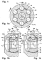
- a joint 11 comprises an outer joint part 12, an inner joint part 13, six torque-transmitting balls 14, and a ball cage 15.
- the cage has a spherical outer surface 16 which is guided in the outer joint part and a spherical inner cage surface 17 which is guided on the inner joint part, said second contact is not mandatory.
- the balls 14 are held in circumferentially distributed cage windows 18 in the ball cage 15 in a joint center plane EM.
- At the outer joint part 12 is a longitudinal axis L12
- at the inner joint part is a longitudinal axis L13.
- the intersection of the longitudinal axes L12, L13 with the joint center plane EM forms the joint center M.
- the outer joint part 12 has a bottom 19, which can for example pass into a connecting pin, and an opening 20 into which a pin connectable with the inner joint part can be inserted.
- the inner joint part 13 has an insertion opening 21.
- the position of the bottom 19 further denotes the axial direction "to the connection side”
- the position of the opening 20 further denotes the axial direction "to the opening side”.
- the ball contact angles ⁇ max / 2 are drawn in both directions for the maximum deflection angle ⁇ max of the inner joint part 13 relative to the outer joint part 12.
- the shape of the first pair of tracks 22 1 , 23 1 is taken from the section AA, the shape of the second pairs of tracks 22 2 , 22 3 the section BB.
- the first balls 14 1 have contact with first outer ball tracks 22 1 in the outer joint part and first inner ball tracks 23 1 in the inner joint part.
- the center lines M22 1 , M23 1 of these tracks are designed in the manner of UF tracks and are composed of a circular arc and a tangential connecting straight line.
- the tangents T22 1 ', T23 1 ' to the balls 14 1 in the contact points with the tracks 22 1 , 23 1 form an opening angle ⁇ 1 , which opens to the opening side.
- the second balls 14 2 are guided in outer ball tracks 22 2 in the outer joint part and inner ball tracks 23 2 in the inner joint part.
- the balls 14 2 are shown with contact in the track base of the ball tracks, which need not necessarily be given.
- the tangents T22 2 ', T23 2 ' to the balls 14 2 at the contact points with the tracks 22 2 , 23 2 form an opening angle ⁇ 2 , which opens to the connection side.
- ⁇ 2 For the description of the ball tracks 22, 23 reference is made below to the center lines M22 2 , M23 2 of the ball tracks.
- tangents T22 2 , T23 2 are drawn at the center lines, which are parallel to the aforementioned tangents T22 2 ', T23 2 '.
- the angle ⁇ 2 between said tangents T22 2 , T23 2 is between 4 and 32 °.
- each pair of tracks with its center lines M22, M23 in a radial plane R 1 , R 2 is through the joint, that these radial planes R have the same angular distance from each other and that in each case a ball 14 from a cage window 18 in the ball cage 15th is recorded.
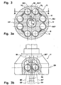
- FIGS. 2a to 2c will be described together below.
- a hinge 11 in this second embodiment comprises ball tracks 22, 23 which lie in track planes BE, BE *, which are arranged in pairs symmetrically to radial planes R through the joint.
- an angled section according to the section line AA is shown, which runs on the one hand through the web plane BE and a first pair of tracks 22 1 , 23 1 with a first ball 14 1 and the other by a radial plane between two pairs of tracks.
- a bent section is shown along the section line BB, which runs on the one hand through a web plane BE * and a second web pair with second ball tracks 22 2 , 23 2 and on the other hand through a radial plane between two web pairs.
- the circumference pairs of pairs of tracks are recognizable, each comprising a first pair of tracks 22 1 , 23 1 and a second pair of tracks 22 2 , 23 2 and which are held in a common cage window 18.
- the pitch angle of these pairs of track pairs is less than between two adjacent track pairs that do not belong to a pair of track pairs.
- First pairs of tracks and second pairs of tracks alternate in the version shown here over the circumference.
- the first balls 22 are 1 and inner tracks 23 1 14 1 performed in the first pairs of tracks from outer tracks, which are formed in the manner of webs from UF joints. That is, the center lines M22, M23 of these pairs of tracks are composed of radii and tangential straight lines connected thereto. Tangents T22 1 ', T23 1 ' to the balls in the tracks form a first opening angle ⁇ 1 , which opens to the opening side of the outer joint part.
- a second ball 14 2 can be seen , which is held in second outer ball tracks 22 2 and second inner ball tracks 23 2 .
- Tangents T22 2 ', T23 2 ' to the balls 14 2 form an opening angle ⁇ 2 with each other, which opens to the connection side of the outer joint part.
- the center lines M22 2 , M23 2 With regard to the trajectory, reference will now be made to the center lines M22 2 , M23 2 .
- tangents T22 2 , 23 2 intersect the center line M22 2 , M23 2 at the already mentioned angle ⁇ 2 .
- the track planes BE, BE * contain parallel axes PE, PE * to the longitudinal axes in smallest distance, thus forming cutting lines between the web planes and a plane perpendicular to the corresponding radial plane R1, R2 reference plane EX1, EX2.
- PE * lie track centers ME, ME * at the shortest distance to the joint center M. If four pairs of tracks symmetrically to three or four radial planes R are arranged with mutually equal pitch angle, joints with twelve or sixteen pairs of tracks 22, 23 and accordingly twelve or sixteen balls 14.
- the center ME1, ME1 * shown in the illustrations b and c is not the joint center, but the center of the path in one of the web planes BE1, BE1 *.
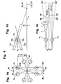
- FIG. 3a The representation a corresponds in principle to the illustration a from FIG. 2, but here a section line A-A is laid parallel to a reference plane EX1 through the balls of a pair of track pairs.
- a first reference plane EB for outer ball tracks is shown, which is perpendicular to said reference plane EX1 and contains a radial ray RS through the joint center point M.
- This reference plane EB forms with a radial plane R through the longitudinal axes L12, L13 a helix angle ⁇ .
- Parallel to the reference plane EB lie the web levels BE and BE *, in which run the center lines of the outer ball tracks of a pair of tracks.
- a first reference plane EB 'for inner ball tracks is also shown, which is also perpendicular to said reference plane EX1 and contains the radial beam RS through the joint center point M.
- This reference plane EB ' forms with the radial plane R through the longitudinal axes L12, L13 a helix angle ⁇ ' which is equal to and opposite to ⁇ .
- Parallel to the reference plane EB ' lie track planes BE', BE * 'in which the center lines of the inner ball tracks of a track pair run. The center lines of each pair of tracks intersect in the joint median plane EM.
- FIGS. 4a to 4c will be described together below.
- a is a cross section through a lying in the joint center plane ball assembly of four ball pairs 14 1 , 14 2 similar to Figure 3 shown.
- the pitch angle between the balls 14 1 , 14 2 of a ball pair and the intermediate radial plane R1 is ⁇ 0 or ⁇ 0 '.
- the ball tracks have a distance from a reference plane EX1, which corresponds to the pitch circle radius PCR multiplied by the cosine of ⁇ 0 .
- the vertical distance of the balls of a pair of balls from said radial plane R1 is denoted by a.
- the marked web levels BE 1 , BE 1 * are representative of the passage of the web levels BE, BE * of the outer ball tracks and for the passage of the web levels BE ', BE *' of the inner ball tracks through the joint center plane.
- a ball pair 14 1 , 14 2 is shown with the outer track planes EB, EB * and the inner track planes EB ', EB *'.
- the constraints D1, D2 of Brutangenten shown in illustration b are also shown.
- FIG. 5 a shows the web center line M22 of an outer ball track 22 according to one of FIGS. 1 to 3 which runs parallel to a web base line.
- the center line M22 of a web in the outer part is composed of a first radius R1 about a center M1 with the first axial offset O1a and a radial offset O1r and a second radius R2 with a second axial offset O2a and a second radial offset O2r.
- the transition is indicated by a turning point W22.
- the second radius R2 is adjoined tangentially by a straight line G3 parallel to the axis L12, PE, PE *.
- the tangent T22 is drawn on the center line M22, which intersects a longitudinal axis L12, PE, PE * at the angle ⁇ / 2.
- a perpendicular on the tangent T22 intersects the longitudinal axis L12, PE;
- Another reference radius RZ is plotted around the center of the track M, ME Left of the median plane EM towards the terminal side 19, the median line M22 extends within the radius RB and outside the radius RZ of the median plane EM towards the opening side 20, the center line M22 extends substantially outside the radius R.
- the radial ball movement of a ball on its way along the ball track with respect to the track center M, ME is denoted by e. where a safety margin is required to avoid edge bearers.
- FIG. 5b shows the web center lines M23 of the associated inner ball tracks 23, which run parallel to the web base lines, according to one of FIGS. 1 to 3.
- the center line M23 of a path 23 in the inner cell 13 is composed of a first radius R1 'around a center M1' and a second radius R2 'around a center M2'. The transition is indicated by a turning point W23.
- the second radius R2 ' is adjoined by a straight line G3' parallel to the axis L13, PE *, PE *, PE ', PE *'.
- the center M1 ' has an axial offset O1a 'and a radial offset O1r' and the center M2 'an axial offset O2a' and a radial offset O2r '.
- the tangent T23 is drawn on the center line M23, which intersects a longitudinal axis L13, PE, PE *, PE ', PE *' at the angle ⁇ / 2.
- a perpendicular on the tangent T23 intersects the longitudinal axis L13, PE; PE *, PE ', PE *' in the reference center MB ', MBE' of a reference radius RB '.
- Another reference radius RZ ' is plotted around the web center M, ME.
- the center line M23 extends within the radius RB 'and outside the radius RZ'. Left of the center plane EM to the connection side 19 toward the center line M23 extends at least predominantly outside the radius RB '.
- the radial ball movement of a ball on its way along the ball track with respect to the track center M, ME is denoted by e.
- the two center lines M22, M23 of Figures 5a, 5b intersect in the joint center plane EM at the angle ⁇ and are mirror-symmetrical to this center plane.
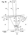
- the web centerline M22 of an outer ball track 22, which runs parallel to a web base line, is shown in a modified embodiment.
- the center line M22 of a web in the outer part consists of a first radius R1 about a center M1 with the first axial offset O1a and a radial offset O1r and a second radius R2 with a second axial offset 02a and a second radial offset O2r and a third radius R3, which is opposite to the radius R2 to the radius R1, smaller than this radius R1 and is curved in the same sense, the position of its center M3 is not measured closer together.
- the transition between the first and second radius is indicated by a turning point W22.
- the second radius R2 is adjoined tangentially by a straight line G3 parallel to the axis L12, PE, PE *.
- the tangent T22 and the center line M22 is shown, which intersects a longitudinal axis L12, PE, PE * at the angle ⁇ / 2.
- a perpendicular on the tangent T22 intersects the longitudinal axis L12, PE; PE * in the reference center MB, MBE of a reference radius RB.
- Another reference radius is plotted around the track center M, ME. Left of the median plane to the terminal side 19 towards the center line M22 extends within the radius RB and outside the radius RZ.
- the center line M22 runs predominantly outside of the radius RB.
- the radial ball movement of a ball on its way along the ball track with respect to the track center M, ME is denoted by e. This corresponds to the minimum thickness of the ball cage in the area of the cage windows, with a safety margin being required to avoid edge beams.
- FIG. 6b shows the web centerlines M23 of the associated inner ball tracks 23 running parallel to the web baselines in a modified embodiment.
- the center line M23 of a track 23 in the inner part 13 is composed of a first radius R1 'about a center M1', a second radius R2 'about a center M2' and a third radius R3 'opposite to the radius R2' at the radius R1 ', smaller than this radius R1, is curved and, in the same sense, curved together.
- the second radius R2 ' is adjoined by a straight line G3' parallel to the axis L13, PE *, PE *, PE ', PE *'.
- the center M1 ' has an axial offset O1a' and a radial offset O1r '
- the center M2' has an axial offset O2a 'and a radial offset O2r'.
- the position of the center M3 ' is not measured in detail.
- the tangent T23 is drawn on the center line M23, which intersects a longitudinal axis L13, PE, PE *, PE ', PE *' at the angle ⁇ / 2.
- a perpendicular on the tangent T23 intersects the longitudinal axis L12, PE; PE *, PE '; PE * 'in the reference center MB', MBE 'of a reference radius RB'.
- Another reference radius RZ ' is plotted around the web center M, ME.
- the center line M23 extends within the radius RB 'and outside the radius RZ'.
- the center line M23 extends predominantly outside the radius RB '.
- the radial ball movement of a ball on its way along the ball track with respect to the track center M, ME is denoted by e.
- the two center lines M22, M23 of Figures 6a, 6b intersect in the joint center plane EM at the angle ⁇ and are mirror-symmetrical to this center plane.
Abstract
Description
Die Erfindung betrifft ein Gleichlaufgelenk in Form eines Gegenbahngelenkes mit den Merkmalen:
- ein Gelenkaußenteil, das eine Längsachse L12 und axial zueinander entgegengesetzt liegend eine Anschlußseite und eine Öffnungsseite hat und das äußere Kugelbahnen aufweist,
- ein Gelenkinnenteil, das eine Längsachse L13 und Anschlußmittel für eine zur Öffnungsseite des Gelenkaußenteils weisende Welle hat und das innere Kugelbahnen aufweist,
- die äußeren Kugelbahnen und die inneren Kugelbahnen bilden Bahnpaare miteinander,
- die Bahnpaare nehmen jeweils eine drehmomentübertragende Kugel auf,
- ein ringförmiger Kugelkäfig sitzt zwischen Gelenkaußenteil und Gelenkinnenteil und weist umfangsverteilte Käfigfenster auf, die jeweils zumindest eine der drehmomentübertragenden Kugeln aufnehmen,
- die Mittelpunkte der Kugeln werden vom Käfig in einer Gelenkmittelebene EM gehalten und bei Gelenkbeugung auf die winkelhalbierende Ebene zwischen den Längsachsen L12, L13 geführt,
- für einen ersten Teil der Bahnpaare öffnet sich der Öffnungswinkel α1 zwischen Tangenten T221', T231' an Bahngrundlinien, die parallel zu Tangenten T221, T231 an die Mittellinien M221, M231 der Kugelbahnen in der Gelenkmittelebene EM bei gestrecktem Gelenk mit zusammenfallenden Längsachsen L12, L13 verlaufen, von der Anschlußseite zur Öffnungsseite, für einen zweiten Teil der Bahnpaare öffnet sich der Öffnungswinkel α2 zwischen Tangenten T222', T232' an Bahngrundlinien, die parallel zu Tangenten T222, T232 an die Mittellinien der Kugelbahnen in der Gelenkmittelebene bei gestrecktem Gelenk mit zusammenfallenden Längsachsen L12, L13 verlaufen, von der Öffnungsseite zur Anschlußseite. Die Mittellinien von Bahnpaaren sind bezüglich der Gelenkmittelebene EM im wesentlichen spiegelbildlich zueinander.
- an outer joint part having a longitudinal axis L12 and axially opposite to each other a terminal side and an opening side and having outer ball tracks,
- an inner joint part having a longitudinal axis L13 and connecting means for a shaft facing the opening side of the outer joint part and having inner ball tracks,
- the outer ball tracks and the inner ball tracks form track pairs with each other,
- the pairs of trains each receive a torque-transmitting ball,
- an annular ball cage sitting between the outer joint part and the inner joint part and has circumferentially distributed cage windows, each receiving at least one of the torque-transmitting balls,
- the centers of the balls are held by the cage in a joint center plane EM and guided in articulation to the bisecting plane between the longitudinal axes L12, L13,
- for a first part of the pairs of tracks, the opening angle α 1 between tangents T22 1 ', T23 1 ' opens at the base line, parallel to tangents T22 1 , T23 1 to the center lines M22 1 , M23 1 of the ball tracks in the joint median plane EM with the joint extended run with coincident longitudinal axes L12, L13, from the terminal side to the opening side, for a second part of the pairs of tracks opens the opening angle α 2 between tangents T22 2 ', T23 2 ' at the railway baseline, the parallel to tangents T22 2 , T23 2 to the center lines of the ball tracks in the joint center plane with the joint extended with coincident longitudinal axes L12, L13, from the opening side to the connection side. The center lines of track pairs are substantially mirror-inverted with respect to the joint median plane EM.
Gegenbahngelenke bekannter Ausführung haben eine gerade Anzahl von Bahnpaaren. Die erste Hälfte dieser Bahnpaare öffnet sich zu Öffnungsseite des Gelenkaußenteils hin. Die andere Hälfte dieser Bahnpaare öffnet sich zur Anschlußseite des Gelenkaußenteils hin. Die Bahnpaare der ersten und zweiten Art sind in Umfangsrichtung betrachtet abwechselnd angeordnet. Dabei sind die Bahnen auf Meridianebenen R angeordnet, die in Umfangsrichtung gleichmäßige Teilungswinkel 360°/n aufweisen, wobei n die Zahl der Bahnpaare darstellt, z. B. 6, 8, 10.Counter-track joints of known design have an even number of pairs of tracks. The first half of this pair of tracks opens to the opening side of the outer joint part. The other half of this pair of tracks opens to the connection side of the outer joint part. The pairs of tracks of the first and second type are arranged alternately when viewed in the circumferential direction. In this case, the tracks are arranged on meridian planes R which have uniform pitch angles of 360 ° / n in the circumferential direction, where n represents the number of track pairs, eg. B. 6, 8, 10th
Die alternierenden Bahnpaare sind dabei so gekrümmt, daß sie in der Gelenkmittelebene EM Tangentenwinkel α1, α2 an die Bahngrundlinien haben, die dem Betrag nach gleich groß sind, jedoch unterschiedliche Orientierung haben, und die Bahnverläufe der alternierenden Bahnpaare sind bezüglich der Gelenkmittelebene gespiegelt.The alternating pairs of tracks are so curved that they have in the joint center plane EM tangent angle α 1 , α 2 to the web baseline, which are equal in magnitude, but have different orientation, and the paths of the alternating pairs of tracks are mirrored with respect to the joint center plane.
Bekannte Gegenbahngelenke erlauben nur relativ kleine Beugewinkel bis 35°. Dies ist bedingt durch die sich zur Anschlußseite des Gelenkaußenteils öffnenden, d. h. zur Öffnungsseite hin schließenden Bahnpaare, die für die notwendige Montierbarkeit des Käfigs in das Gelenkaußenteil in Richtung zur Öffnungsseite hin nur relativ kurz ausgeführt sein können.Known antireflective joints allow only relatively small flexion angles up to 35 °. This is due to the opening to the connection side of the outer joint part, d. H. to the opening side closing path pairs that can be made only relatively short for the necessary mountability of the cage in the outer joint part in the direction of the opening side.
Aus der
- im Gelenkaußenteil wandert die Mittellinie der Kugelbahnen im Bereich von der Gelenkmittelebene EM bis zur Öffnungsseite hin über einen Bezugsradius RB, dessen Radiusmittelpunkt MB im Schnittpunkt einer Senkrechten auf der Tangenten an die Mittellinie der Kugelbahn in der Gelenkmittelebene EM und der Längsachse L12 liegt, radial nach außen hinaus und
- im Gelenkinnenteil wandert die Mittellinie der Kugelbahnen im Bereich von der Gelenkmittelebene EM bis zur Anschlußseite hin über einen Bezugsradius RB', dessen Radiusmittelpunkt MB' im Schnittpunkt einer senkrechten auf der Tangenten an die Mittellinie der Kugelbahn in der Gelenkmittelebene EM und der Längsachse L13 liegt, radial nach außen hinaus.
- in the outer joint part, the center line of the ball tracks moves in the area of the joint center plane EM to the opening side over a reference radius RB, the radius center MB is at the intersection of a perpendicular to the tangent to the center line of the ball track in the joint center plane EM and the longitudinal axis L12, radially outward and
- in the inner joint part, the center line of the ball tracks in the area from the joint center plane EM to the connection side moves radially over a reference radius RB 'whose radius center MB' is at the intersection of a perpendicular tangent to the center line of the ball track in the joint center plane EM and the longitudinal axis L13 outward.
Aus der
Aus der
Der vorliegenden Erfindung liegt die Aufgabe zugrunde, Gegenbahngelenke der eingangs genannten Art mit erhöhten Beugewinkeln bereitzustellen.The present invention has for its object to provide counter track joints of the type mentioned with increased bending angles.
Eine erste Lösung liegt in einem Gleichlaufgelenk in Form eines Gegenbahngelenkes mit den Merkmalen:
- ein Gelenkaußenteil, das eine Längsachse L12 und axial zueinander entgegengesetzt liegend eine Anschlußseite und eine Öffnungsseite hat und das äußere Kugelbahnen aufweist,
- ein Gelenkinnenteil, das eine Längsachse L13 und Anschlußmittel für eine zur Öffnungsseite des Gelenkaußenteils weisende Welle hat und das innere Kugelbahnen aufweist,
- die äußeren Kugelbahnen und die inneren Kugelbahnen bilden Bahnpaare miteinander,
- die Bahnpaare nehmen jeweils eine drehmomentübertragende Kugel auf,
- ein ringförmiger Kugelkäfig sitzt zwischen Gelenkaußenteil und Gelenkinnenteil und weist umfangsverteilte Käfigfenster auf, die jeweils zumindest eine der drehmomentübertragenden Kugeln aufnehmen,
- die Mittelpunkte der Kugeln werden vom Käfig in einer Gelenkmittelebene gehalten und bei Gelenkbeugung auf die winkelhalbierende Ebene zwischen den Längsachsen geführt,
- die Mittellinien M22, M23 der Kugelbahnen von Bahnpaaren liegen in Radialebenen R durch das Gelenk,
- für einen ersten Teil der Bahnpaare öffnet sich der Öffnungswinkel α1 zwischen Tangenten T221', T231' an Bahngrundlinien, die parallel zu den Tangenten T221, T231 an die Mittellinien M221, M231 der Kugelbahnen in der Gelenkmittelebene EM bei gestrecktem Gelenk mit zusammenfallenden Längsachsen L12, L13 verlaufen, von der Anschlußseite zur Öffnungsseite,
- für einen zweiten Teil der Bahnpaare öffnet sich der Öffnungswinkel α2 zwischen Tangenten T222 , T232' an Bahngrundlinien, die parallel zu den Tangenten T222, T232 an die Mittellinien M222, M232 der Kugelbahnen in der Gelenkmittelebene EM bei gestrecktem Gelenk mit zusammenfallenden Längsachsen L12, L13 verlaufen, von der Öffnungsseite zur Anschlußseite, hierbei gilt für die Mittellinien der zweiten Bahnpaare:
- im Gelenkaußenteil verläßt die Mittellinie M222 der Kugelbahnen im Bereich von der Gelenkmittelebene EM bis zur Anschlußseite hin jeweils einen Bezugsradius RB, dessen Radiusmittelpunkt MB im Schnittpunkt einer Senkrechten auf der Tangenten T222 an die Mittellinie M222 der Kugelbahn in der Gelenkmittelebene EM und der Längsachse L12 liegt, radial nach innen,
- im Gelenkinnenteil verläßt die Mittellinie M232 der Kugelbahnen im Bereich von der Gelenkmittelebene EM bis zur Öffnungsseite hin jeweils einen Bezugsradius RB', dessen Radiusmittelpunkt MB' im Schnittpunkt einer Senkrechten auf der Tangenten T232 an die Mittellinie M232 der Kugelbahn in der Gelenkmittelebne EM und der Längsachse L13 liegt, radial nach innen,
- im Gelenkaußenteil wandert die Mittellinie M222 der Kugelbahnen im Bereich von der Gelenkmittelebene EM bis zur Öffnungsseite hin über den genannten Bezugsradius RB radial nach außen hinaus und
- im Gelenkinnenteil wandert die Mittellinie M232 der Kugelbahnen im Bereich von der Gelenkmittelebene EM bis zur Anschlußseite hin über den genannten Bezugsradius RB' radial nach außen hinaus.
- an outer joint part having a longitudinal axis L12 and axially opposite to each other a terminal side and an opening side and having outer ball tracks,
- an inner joint part having a longitudinal axis L13 and connecting means for a shaft facing the opening side of the outer joint part and having inner ball tracks,
- the outer ball tracks and the inner ball tracks form track pairs with each other,
- the pairs of trains each receive a torque-transmitting ball,
- an annular ball cage sitting between the outer joint part and the inner joint part and has circumferentially distributed cage windows, each receiving at least one of the torque-transmitting balls,
- the centers of the balls are held by the cage in a joint center plane and guided at articulation on the bisecting plane between the longitudinal axes,
- the center lines M22, M23 of the ball tracks of track pairs lie in radial planes R through the joint,
- for a first part of the pairs of orbits, the opening angle α 1 between tangents T22 1 ', T23 1 ' opens at the railway base lines parallel to the tangents T22 1 , T23 1 to the center lines M22 1 , M23 1 of the ball tracks in the joint median plane EM at stretched Joint with coincident longitudinal axes L12, L13 extend, from the connection side to the opening side,
- for a second part of the pairs of orbits, the opening angle α 2 between tangents T22 2 , T23 2 'opens at the railway base lines parallel to the tangents T22 2 , T23 2 to the center lines M22 2 , M23 2 of the ball tracks in the joint median plane EM with the joint extended run with coincident longitudinal axes L12, L13, from the opening side to the terminal side, in this case applies to the center lines of the second pairs of tracks:
- in the outer joint part leaves the center line M22 2 of the ball tracks in the range of the joint center plane EM to the connection side each have a reference radius RB, the radius center MB at the intersection of a perpendicular on the tangent T22 2 to the center line M22 2 of the ball track in the joint median plane EM and the longitudinal axis L12 is located, radially inward,
- in the inner joint part leaves the center line M23 2 of the ball tracks in the range from the joint center plane EM to the opening side each have a reference radius RB 'whose radius center MB' at the intersection of a perpendicular on the tangent T23 2 to the center line M23 2 of the ball track in the Gelenkmittelebne EM and the longitudinal axis L13 lies radially inward,
- in the outer joint part, the center line M22 2 of the ball tracks travels in the area from the joint center plane EM to the opening side over the reference radius RB radially outward and outward
- in the inner joint part, the center line M23 2 of the ball tracks in the region of the joint center plane EM to the connection side over the said reference radius RB 'moves radially outward.
Mit der hiermit angegebenen Bahnform ist eine Vergrößerung des maximalen Beugewinkels im Vergleich mit bekannten Bahnformen möglich. Das erstgenannte Merkmal, nach dem die Mittellinien die Bezugsradien nach innen verlassen, kann unmittelbar an der Gelenkmittelebene beginnen oder auch später einsetzen, wobei es sich dabei insbesondere progressiv zunehmend verhalten kann. Das als zweites genannte Merkmal, nach dem die Mittellinien über den Bezugsradius nach außen wandern, schließt ein unmittelbares Abwandern vom Bezugsradius nach außen ebenso ein wie ein erst späteres Kreuzen des Bezugsradius und nachfolgendes Abwandern nach außen.With the web form indicated hereby, an increase of the maximum bending angle is possible in comparison with known web shapes. The former feature, according to which the center lines leave the reference radii inwards, can start immediately at the joint center plane or even later, whereby it can behave progressively increasingly in particular. The second feature, according to which the center lines travel outwardly beyond the reference radius, involves an immediate outward migration from the reference radius as well as a later later crossing of the reference radius and subsequent outward migration.
Nach einer bevorzugten Weiterbildung ist das Gleichlaufgelenk mit den weiteren Merkmalen der zweiten Bahnpaare versehen:
- im Gelenkaußenteil ist der örtliche Radius R1 der Mittellinie M222 in der Gelenkmittelebene EM kleiner als der Bezugsradius RB,
- im Gelenkinnenteil ist der örtliche Radius R1' der Mittellinie M232 in der Gelenkmittelebene EM kleiner als der Bezugsradius RB'.
- in the outer joint part, the local radius R1 of the center line M22 2 in the joint center plane EM is smaller than the reference radius RB,
- in the inner joint part, the local radius R1 'of the center line M23 2 in the joint center plane EM is smaller than the reference radius RB'.
Nach einer bevorzugten Weiterbildung ist das Gleichlaufgelenk mit den weiteren Merkmalen der zweiten Bahnpaare versehen:
- im Gelenkaußenteil verläuft die Mittellinie M222 der Kugelbahnen von der Gelenkmittelebene EM zur Anschlußseite hin jeweils radial außerhalb eines Bezugsradius RZ, dessen Radiusmittelpunkt im Gelenkmittelpunkt M liegt, und
- im Gelenkinnenteil verläuft die Mittellinie M232 der Kugelbahnen von der Gelenkmittelebene EM zur Öffnungsseite hin jeweils radial außerhalb eines Bezugsradius RZ', dessen Radiusmittelpunkt im Gelenkmittelpunkt M liegt.
- in the outer joint part, the center line M22 2 of the ball tracks extends from the joint center plane EM to the connection side in each case radially outside a reference radius RZ whose radius center is located in the joint center M, and
- in the inner joint part, the center line M23 2 of the ball tracks extends from the joint center plane EM towards the opening side in each case radially outside a reference radius RZ 'whose radius center lies in the joint center point M.
Eine weitere vorteilhafte Ausführung liegt in den weiteren Merkmalen der zweiten Bahnpaare:
- im Gelenkaußenteil verläuft die Mittellinie M222 der Kugelbahnen von der Gelenkmittelebene EM zur Öffnungsseite hin jeweils radial außerhalb des Bezugsradius RB und
- im Gelenkinnenteil verläuft die Mittellinie M232 der Kugelbahnen von der Gelenkmittelebene EM zur Anschlußseite hin jeweils radial außerhalb des Bezugsradius RB'.
- in the outer joint part, the center line M22 2 of the ball tracks extends from the joint center plane EM to the opening side in each case radially outside of the reference radius RB and
- in the inner joint part, the center line M23 2 of the ball tracks extends from the joint center plane EM to the connection side in each case radially outside the reference radius RB '.
In weiterer Ausgestaltung werden die folgenden weiteren Merkmale vorgeschlagen :
- im Gelenkaußenteil verläuft die Mittellinie M222 der Kugelbahnen von der Gelenkmittelebene EM zur Öffnungsseite hin jeweils radial innerhalb eines Bezugsradius RZ um den Gelenkmittelpunkt M und
- im Gelenkinnenteil verläuft die Mittellinie M232 der Kugelbahnen von der Gelenkmittelebene EM zur Anschlußseite hin jeweils radial innerhalb eines Bezugsradius RZ' um den Gelenkmittelpunkt M.
- in the outer joint part, the center line M22 2 of the ball tracks extends from the joint center plane EM to the opening side in each case radially within a reference radius RZ about the joint center M and
- in the inner joint part, the center line M23 2 of the ball tracks extends from the joint center plane EM to the connection side in each case radially within a reference radius RZ 'around the joint center M.
Nach einer weiteren Ausgestaltung werden die weiteren Merkmale der zweiten Bahnpaare vorgeschlagen:
- die Mittellinien M222, M232 der äußeren Kugelbahnen und inneren Kugelbahnen umfassen jeweils zumindest zwei entgegengesetzt gekrümmte Bogenabschnitte, die in einem Wendepunkt aneinander anschließen,
- die Wendepunkte W222 der äußeren Kugelbahnen liegen mit Abstand von der Mittelebene EM zur Öffnungsseite,
- die Wendepunkte W232 der inneren Kugelbahnen liegen mit Abstand von der Mittelebene EM zur Anschlußseite,
- die Wendepunkte W222, W232 liegen jeweils unterhalb eines Maximums des Abstands der Mittellinien M222, M232 von den Längsachsen L12, L13.
- the center lines M22 2 , M23 2 of the outer ball tracks and inner ball tracks each comprise at least two oppositely curved arc sections which adjoin one another in a turning point,
- the turning points W22 2 of the outer ball tracks are at a distance from the center plane EM to the opening side,
- the inflection points W23 2 of the inner ball tracks are at a distance from the center plane EM to the connection side,
- the inflection points W22 2 , W23 2 are each below a maximum of the distance of the center lines M22 2 , M23 2 from the longitudinal axes L12, L13.
Ein konkretes Ausgestaltungsbeispiel weist die Merkmale der zweiten Bahnpaare auf:
- die Bahnmittellinien M222 der äußeren Kugelbahnen haben einen ersten Bogen mit dem Radius R1, dessen Mittelpunkt M1 um einen ersten axialen Offset O1a von der Mittelebene EM des Gelenks zur Anschlußseite hin versetzt liegt und um einen ersten radialen Offset O1r von der Längsachse L12 nach außen zur Kugelbahn hin versetzt liegt und anschließend an diesen Bogen zur Anschlußseite hin einen zweiten Bogen mit dem Radius R2, dessen Mittelpunkt M2 um einen zweiten axialen Offset O2a von der Mittelebene EM des Gelenks zur Öffnungsseite hin versetzt liegt und um einen zweiten radialen Offset O2r, der größer ist als die Summe aus dem ersten Radius R1 und dem ersten radialen Offset O1r, von der Längsachse L12 nach außen hin versetzt liegt,
- die Bahnmittellinien M232 der inneren Kugelbahnen haben einen ersten Bogen mit dem Radius R1', dessen Mittelpunkt M1' um einen ersten axialen Offset O1a' von der Mittelebene EM des Gelenks zur Öffnungsseite hin versetzt liegt und um einen ersten radialen Offset O1r' von der Längsachse L13 nach außen zur Kugelbahn hin versetzt liegt und anschließend an diesen Bogen zur Öffnungsseite hin einen zweiten Bogen mit dem Radius R2', dessen Mittelpunkt um einen zweiten axialen Offset O2a' von der Mittelebene EM des Gelenks zur Anschlußseite hin versetzt liegt und um einen zweiten radialen Offset O2r', der größer ist als die Summe aus dem ersten Radius R1' und dem ersten radialen Offset O1r', von der Längsachse L13 nach außen hin versetzt liegt.
- the track centerlines M22 2 of the outer ball tracks have a first arc of radius R1 whose center point M1 is offset by a first axial offset O1a from the center plane EM of the joint to the terminal side and by a first radial offset O1r from the longitudinal axis L12 outwards Ball track is offset and then to this sheet to the connection side, a second Arc of radius R2 whose center M2 is offset by a second axial offset O2a from the center plane EM of the joint to the opening side and by a second radial offset O2r which is greater than the sum of the first radius R1 and the first radial offset O1r, offset from the longitudinal axis L12 to the outside,
- the track centerlines M23 2 of the inner ball tracks have a first arc of radius R1 ', the center M1' of which is offset by a first axial offset O1a 'from the center plane EM of the joint to the opening side and a first radial offset O1r' from the longitudinal axis L13 is outwardly offset to the ball track out and then to this arc to the opening side towards a second arc with the radius R2 ', the center is offset by a second axial offset O2a' from the median plane of the joint EM to the connection side and a second radial Offset O2r ', which is greater than the sum of the first radius R1' and the first radial offset O1r ', offset from the longitudinal axis L13 to the outside.
Hierbei werden insbesondere die weiteren Merkmale der zweiten Bahnpaare vorgesehen:
- der Krümmungsradius der Mittellinien M22 der äußeren Kugelbahnen nimmt im Verlauf von der Mittelebene EM zur Anschlußseite ab und der Krümmungsradius der
- the radius of curvature of the center lines M22 of the outer ball tracks decreases in the course of the median plane EM to the terminal side and the radius of curvature of
Mittelebene M23 der inneren Kugelbahnen nimmt im Verlauf von der Mittelebene EM zur Öffnungsseite ab.Center plane M23 of the inner ball tracks decreases in the course of the center plane EM to the opening side.
Hierbei werden insbesondere die weiteren Merkmale der zweiten Bahnpaare vorgesehen:
- die Bahnmittellinien M222 der äußeren Kugelbahnen haben einen dritten Bogen mit dem Radius R3, der sich tangential mit gleichem Krümmungssinn an den ersten Bogen mit dem Radius R1 anschließt und dessen Radius R3 kleiner ist, als der Radius R1 und
- die Bahnmittellinien M232 der inneren Kugelbahnen haben einen dritten Bogen mit dem Radius R3', der sich tangential mit gleichem Krümmungssinn an den ersten Bogen mit dem Radius R1' anschließt und dessen Radius R3' kleiner ist, als der Radius R1'.
- the track centerlines M22 2 of the outer ball tracks have a third arc with the radius R3, which connects tangentially with the same sense of curvature to the first arc with the radius R1 and whose radius R3 is smaller than the radius R1 and
- the track centerlines M23 2 of the inner ball tracks have a third arc with the radius R3 ', which connects tangentially with the same sense of curvature to the first arc with the radius R1' and whose radius R3 'is smaller than the radius R1 '.
In weiterer Ausgestaltung wird vorgeschlagen daß sich an den zweiten Bahnpaaren im Verlauf der Mittellinie M222 der äußeren Kugelbahnen zur Öffnungsseite hin an den zweiten Bogen eine achsparallele Gerade G3 anschließt und daß sich im Verlauf der Mittellinie der inneren Kugelbahnen M232 im Anschluß an den zweiten Bogen zur Anschlußseite hin eine achsparallele Gerade G3' anschließt.In a further embodiment, it is proposed that an axially parallel straight line G3 connects to the second track pairs in the course of the center line M22 2 of the outer ball tracks to the opening side and that in the course of the center line of the inner ball tracks M23 2 following the second arc to the connection side, an axis-parallel straight line G3 'connects.
Gemäß einer dazu alternativen Ausgestaltung ist vorgesehen, daß sich an den zweiten Bahnpaaren im Verlauf der Mittellinie M222 der äußeren Kugelbahnen zur Öffnungsseite hin an den zweiten Bogen eine sich der Längsachse L12 annähernde Gerade anschließt und daß sich im Verlauf der Mittellinie M232 der inneren Kugelbahnen im Anschluß an den zweiten Bogen zur Anschlußseite hin eine sich der Längsachse L13 annähernde Gerade anschließt.According to an alternative embodiment, it is provided that connects to the second track pairs in the course of the center line M22 2 of the outer ball tracks to the opening side to the second arc an approximately longitudinal axis L12 straight line and that in the course of the center line M23 2 of the inner ball tracks following the second arc to the connection side, a straight line approximating the longitudinal axis L13 connects.
Nach einem weiteren Merkmal wird vorgeschlagen, daß sich an den zweiten Bahnpaaren die Mittellinien M22, M23 der Kugelbahnen in der Gelenkmittelebene EM unter einem Winkel von 4 bis 32° schneiden, wobei die Tangenten T22, T23 an die Mittellinien M22, M23 der Kugelbahnen aller Bahnpaare bei gestrecktem Gelenk einen gleich großen Öffnungswinkel α bilden.According to a further feature, it is proposed that intersect at the second track pairs the center lines M22, M23 of the ball tracks in the joint center plane EM at an angle of 4 to 32 °, the tangents T22, T23 to the center lines M22, M23 of the ball tracks of all pairs of tracks form an equal opening angle α when the joint is stretched.
Hierbei sind vorzugsweise erste Bahnpaare und zweite Bahnpaare über dem Umfang abwechselnd angeordnet. Die Radialebenen R1 der ersten Bahnpaare und die Radialebenen R2 der zweiten Bahnpaare können hierbei in Umfangsrichtung insbesondere gleiche Teilungswinkel aufweisen. In besonderer Ausführung kann vorgesehen sein, daß die Verläufe der ersten Bahnpaare und der zweiten Bahnpaare nicht symmetrisch in Bezug auf die Gelenkmittelebene EM sind. Insbesondere können die ersten Bahnpaare analog zu den Bahnpaaren von UF-Gelenken von der Gelenköffnungsseite betrachtet hinterschnittfrei ausgebildet sein.In this case, first pairs of tracks and second pairs of tracks are preferably arranged alternately over the circumference. The radial planes R1 of the first pairs of tracks and the radial planes R2 of the second pairs of tracks can in this case have in the circumferential direction in particular equal pitch angles. In a particular embodiment, it can be provided that the courses of the first pairs of tracks and the second pairs of tracks are not symmetrical with respect to the joint center plane EM. In particular, the first pairs of tracks may be formed undercut-free, as viewed in the joint pairs of UF joints, viewed from the joint opening side.
Nach einer weiteren bevorzugten Ausführungsform ist vorgesehen, daß der Rollkreisradius PCR1 der Kugeln der ersten Bahnpaare kleiner ist als der Rollkreisradius PCR2 der Kugeln der zweiten Bahnpaare.According to a further preferred embodiment, it is provided that the rolling circle radius PCR 1 of the balls of the first pair of tracks is smaller than the pitch circle radius PCR 2 of the balls of the second pairs of tracks.
Eine zweite Lösung besteht in einem Gleichlaufgelenk in Form eines Gegenbahngelenkes mit den Merkmalen:
- ein Gelenkaußenteil, das eine Längsachse L12 und axial zueinander entgegengesetzt liegend eine Anschlußseite und eine Öffnungsseite hat und das äußere Kugelbahnen aufweist,
- ein Gelenkinnenteil, das eine Längsachse L13 und Anschlußmittel für eine zur Öffnungsseite des Gelenkaußenteils weisende Welle hat und das innere Kugelbahnen aufweist,
- die äußeren Kugelbahnen und die inneren Kugelbahnen bilden Bahnpaare miteinander,
- die Bahnpaare nehmen jeweils eine drehmomentübertragende Kugel auf,
- ein ringförmiger Kugelkäfig sitzt zwischen Gelenkaußenteil und Gelenkinnenteil und weist umfangsverteilte Käfigfenster auf, die jeweils zumindest eine der drehmomentübertragenden Kugeln aufnehmen,
- die Mittelpunkte der Kugeln werden vom Käfig in einer Gelenkmittelebene EM gehalten und bei Gelenkbeugung auf die winkelhalbierende Ebene zwischen den Längsachsen L12, L13 geführt,
- die Mittellinien M22, M23 der Kugelbahnen von Bahnpaaren liegen in Paaren von Bahnebenen BE, BE*, die parallel zueinander und symmetrisch zu Radialebenen R1, R2 durch die Längsachsen L12, L13 verlaufen,
- für einen ersten Teil der Bahnpaare öffnet sich der Öffnungswinkel α1 zwischen Tangenten T221', T231' an Bahngrundlinien, die parallel zu Tangenten T221, T232 an die Mittellinien M221, M231 der Kugelbahnen in der Gelenkmittelebene EM bei gestrecktem Gelenk mit zusammenfallenden Längsachsen L12, L13 verlaufen von der Anschlußseite zur Öffnungsseite,
- für einen zweiten Teil der Bahnpaare öffnet sich der Öffnungswinkel α2 zwischen Tangenten T222', T232' an Bahngrundlinien, die parallel zu Tangenten T222, T232 an die Mittellinien M222, M232 der Kugelbahnen in der Gelenkmittelebene EM bei gestrecktem Gelenk mit zusammenfallenden Längsachsen L12, L13 verlaufen, von der Öffnungsseite zur Anschlußseite, hierbei gilt für die Mittellinien der zweiten Bahnpaare
- im Gelenkaußenteil verläßt die Mittellinie M222 der Kugelbahnen im Bereich von der Gelenkmittelebene EM bis zur Anschlußseite hin jeweils einen Bezugsradius RB, dessen Radiusmittelpunkt MBE im Schnittpunkt einer Senkrechten auf der Tangenten T222 an die Mittellinie M222 der Kugelbahn in der Gelenkmittelebene EM und einer Parallelachse PE, PE* zur Längsachse L12 durch eine Bahnebene BE, BE* liegt, radial nach innen,
- im Gelenkinnenteil verläßt die Mittellinie M232 der Kugelbahnen im Bereich von der Gelenkmittelebene EM bis zur Öffnungsseite hin jeweils einen Bezugsradius RB', dessen Radiusmittelpunkt MBE' im Schnittpunkt einer Senkrechten auf der Tangenten T232 an die Mittellinie M232 der Kugelbahn in der Gelenkmittelebene EM und einer Parallelachse PE, PE* zur Längsachse L13 durch eine Bahnebene BE, BE* liegt, radial nach innen,
- im Gelenkaußenteil wandert die Mittellinie M222 der Kugelbahnen im Bereich von der Gelenkmittelebene EM bis zur Öffnungsseite hin über den genannten Bezugsradius RB radial nach außen hinaus und
- im Gelenkinnenteil wandert die Mittellinie M232 der Kugelbahnen im Bereich von der Gelenkmittelebene EM bis zur Anschlußseite hin über den genannten Bezugsradius RB' radial nach außen hinaus.
- an outer joint part having a longitudinal axis L12 and axially opposite to each other a terminal side and an opening side and having outer ball tracks,
- an inner joint part having a longitudinal axis L13 and connecting means for a shaft facing the opening side of the outer joint part and having inner ball tracks,
- the outer ball tracks and the inner ball tracks form track pairs with each other,
- the pairs of trains each receive a torque-transmitting ball,
- an annular ball cage sitting between the outer joint part and the inner joint part and has circumferentially distributed cage windows, each receiving at least one of the torque-transmitting balls,
- the centers of the balls are held by the cage in a joint center plane EM and guided in articulation to the bisecting plane between the longitudinal axes L12, L13,
- the center lines M22, M23 of the ball tracks of track pairs lie in pairs of track planes BE, BE * which run parallel to one another and symmetrically to radial planes R1, R2 through the longitudinal axes L12, L13,
- for a first part of the pairs of tracks opens the opening angle α 1 between tangents T22 1 ', T23 1 ' to the base line, parallel to tangents T22 1 , T23 2 to the center lines M22 1 , M23 1 of the ball tracks in the joint median plane EM with the joint extended with coincident longitudinal axes L12, L13 extend from the connection side to the opening side,
- for a second part of the pairs of orbits, the opening angle α 2 between tangents T22 2 ', T23 2 ' opens at the railway base lines parallel to tangents T22 2 , T23 2 to the center lines M22 2 , M23 2 of the ball tracks in the joint median plane EM with the joint extended run with coincident longitudinal axes L12, L13, from the opening side to the terminal side, in this case applies to the center lines of the second pairs of tracks
- in the outer joint part leaves the center line M22 2 of the ball tracks in the area of the Joint center plane EM to the connection side each have a reference radius RB, the radius center MBE at the intersection of a perpendicular on the tangent T22 2 to the center line M22 2 of the ball track in the joint center plane EM and a parallel axis PE, PE * to the longitudinal axis L12 by a web plane BE, BE * lies, radially inward,
- in the inner joint part leaves the center line M23 2 of the ball tracks in the range from the joint center plane EM to the opening side each have a reference radius RB ', the radius center MBE' at the intersection of a vertical on the tangent T23 2 to the center line M23 2 of the ball track in the joint median plane EM and a parallel axis PE, PE * to the longitudinal axis L13 through a web plane BE, BE *, radially inward,
- in the outer joint part, the center line M22 2 of the ball tracks in the range from the joint center plane EM to the opening side over the said reference radius RB moves radially outward and
- in the inner joint part, the center line M23 2 of the ball tracks in the region of the joint center plane EM to the connection side over the said reference radius RB 'moves radially outward.
Die hiermit vorgeschlagene Lösung unterscheidet sich von der erstgenannten, bei der die Mittellinien von Bahnpaaren in Radialebenen durch die Mittelachsen des Gelenkes liegen, dadurch, daß im vorliegenden Fall die Mittellinien von Bahnpaaren jeweils zweier benachbarter Kugeln in zwei zueinander parallelen und symmetrisch und parallel zu einer Radialebene R angeordneten Bahnebenen BE, BE*, verlaufen. Die Radialebene R ist dabei wie bei der ersten Lösung durch die Längsachsen L12, L13 bei gestrecktem Gelenk definiert. Bei grundsätzlich gleicher Bahnform wie bei der ersten Lösung beziehen sich die Bahnformen bei der zweiten Lösung jedoch auf Parallelachsen PE, PE*, die in einer auf der Radialebene R senkrecht liegenden Bezugsebene EX durch die Längsachsen L12, L13 liegen, sowie auf Bezugsmittelpunkte ME, die auf den genannten Parallelachsen PE, PE* und im Schnittpunkt der Parallelachsen mit der Gelenkmittelebene EM liegen.The solution proposed here differs from the former, in which the center lines of track pairs lie in radial planes through the central axes of the joint, characterized in that in the present case the center lines of pairs of two adjacent balls in two mutually parallel and symmetrical and parallel to a radial plane R arranged orbital BE, BE *, run. The radial plane R is defined as in the first solution by the longitudinal axes L12, L13 with the joint extended. In principle, the same web shape as in the first solution, the web shapes in the second solution, however, refer to parallel axes PE, PE *, which lie in a plane lying on the radial plane R reference plane EX through the longitudinal axes L12, L13, and on reference centers ME, the lie on said parallel axes PE, PE * and at the intersection of the parallel axes with the joint center plane EM.
Eine dritte Lösung besteht in einem Gleichlaufdrehgelenk in Form eines Gegenbahngelenks mit den Merkmalen:
- ein Gelenkaußenteil, das eine Längsachse L12 und axial zueinander entgegengesetzt liegend eine Anschlußseite und eine Öffnungsseite hat und das äußere Kugelbahnen aufweist,
- ein Gelenkinnenteil, das eine Längsachse L13 und Anschlußmittel für eine zur Öffnungsseite des Gelenkaußenteils weisende Welle hat und das innere Kugelbahnen aufweist,
- die äußeren Kugelbahnen und die inneren Kugelbahnen bilden Bahnpaare miteinander,
- die Bahnpaare nehmen jeweils eine drehmomentübertragende Kugel auf,
- ein ringförmiger Kugelkäfig sitzt zwischen Gelenkaußenteil und Gelenkinnenteil und weist umfangsverteilte Käfigfenster auf, die jeweils zumindest eine der drehmomentübertragenden Kugeln aufnehmen,
- die Mittelpunkte der Kugeln werden vom Käfig in einer Gelenkmittelebene EM gehalten und bei Gelenkbeugung auf die winkelhalbierende Ebene zwischen den Längsachsen L12, L13 geführt,
- die Mittellinien M221, M222 benachbarter Kugelbahnen im Gelenkaußenteil liegen in Paaren von ersten Bahnebenen BE, BE*, die parallel zueinander und symmetrisch zu Radialstrahlen RS1, RS2 durch den Gelenkmittelpunkt M verlaufen,
- die Mittellinien M231, M232 benachbarter Kugelbahnen im Gelenkinnenteil liegen in Paaren von zweiten Bahnebenen BE', BE*', die parallel zueinander und symmetrisch zu Radialstrahlen RS1, RS2 durch den Gelenkmittelpunkt M verlaufen,
- die ersten Bahnebenen BE, BE* und die zweiten Bahnebenen BE', BE*' bilden mit Radialebenen R1, R2 durch die Längsachsen L12, L13 gleich große, entgegengesetzt angetragene Winkel γ, γ',
- für einen ersten Teil der Bahnpaare öffnet sich der Öffnungswinkel α1 zwischen Tangenten T221', T231' an Bahngrundlinien, die parallel zu Tangenten T221, T231 an die Mittellinien M221, M231 der Kugelbahnen in der Gelenkmittelebene EM bei gestrecktem Gelenk mit zusammenfallenden Längsachsen L12, L13 verlaufen von der Anschlußseite zur öffnungsseite,
- für einen zweiten Teil der Bahnpaare öffnet sich der Öffnungswinkel α2 zwischen Tangenten T222', T232' an Bahngrundlinien, die parallel zu Tangenten T222, T232 an die Mittellinien M222, M232 der Kugelbahnen in der Gelenkmittelebene EM bei gestrecktem Gelenk mit zusammenfallenden Längsachsen L12, L13 verlaufen, von der öffnungsseite zur Anschlußseite, hierbei gilt für die Mittellinien der zweiten Bahnpaare
- im Gelenkaußenteil verläßt die Mittellinie M222 der Kugelbahnen im Bereich von der Gelenkmittelebene EM bis zur Anschlußseite hin jeweils einen Bezugsradius RB, dessen Radiusmittelpunkt MBE im Schnittpunkt einer Senkrechten auf der Tangenten T222 an die Mittellinie M222 der Kugelbahn in der Gelenkmittelebene EM und einer Bezugsachse PE, PE* durch eine Bahnebene BE, BE* liegt, radial nach innen,
- im Gelenkinnenteil verläßt die Mittellinie M232 der Kugelbahnen im Bereich von der Gelenkmittelebene EM bis zur Öffnungsseite hin jeweils einen Bezugsradius RB', dessen Radiusmittelpunkt MBE' im Schnittpunkt einer Senkrechten auf der Tangenten T232 an die Mittellinie M232 der Kugelbahn in der Gelenkmittelebene EM und einer Bezugsachse PE', PE*' durch eine Bahnebene BE', BE*' liegt, radial nach innen,
- im Gelenkaußenteil wandert die Mittellinie M222 der Kugelbahnen im Bereich von der Gelenkmittelebene EM bis zur Öffnungsseite hin über den genannten Bezugsradius RB radial nach außen hinaus und
- im Gelenkinnenteil wandert die Mittellinie M232 der Kugelbahnen im Bereich von der Gelenkmittelebene EM bis zur Anschlußseite hin über den genannten Bezugsradius RB' radial nach außen hinaus.
- an outer joint part having a longitudinal axis L12 and axially opposite to each other a terminal side and an opening side and having outer ball tracks,
- an inner joint part having a longitudinal axis L13 and connecting means for a shaft facing the opening side of the outer joint part and having inner ball tracks,
- the outer ball tracks and the inner ball tracks form track pairs with each other,
- the pairs of trains each receive a torque-transmitting ball,
- an annular ball cage sitting between the outer joint part and the inner joint part and has circumferentially distributed cage windows, each receiving at least one of the torque-transmitting balls,
- the centers of the balls are held by the cage in a joint center plane EM and guided in articulation to the bisecting plane between the longitudinal axes L12, L13,
- the center lines M22 1 , M22 2 of adjacent ball tracks in the outer joint part lie in pairs of first track planes BE, BE *, which run parallel to one another and symmetrically to radial rays RS1, RS2 through the joint center M,
- the center lines M23 1 , M23 2 of adjacent ball tracks in the inner joint part lie in pairs of second track planes BE ', BE *' which run parallel to one another and symmetrically to radial rays RS1, RS2 through the joint center M,
- the first track planes BE, BE * and the second track planes BE ', BE *' form, with radial planes R1, R2 through the longitudinal axes L12, L13, equal, opposite angles γ, γ ',
- for a first part of the pairs of tracks, the opening angle α 1 between tangents T22 1 ', T23 1 ' opens at the base line, parallel to tangents T22 1 , T23 1 to the center lines M22 1 , M23 1 of the ball tracks in the joint median plane EM with the joint extended with coincident longitudinal axes L12, L13 extend from the connection side to the opening side,
- for a second part of the pairs of orbits, the opening angle α 2 between tangents T22 2 ', T23 2 ' opens at the railway base lines parallel to tangents T22 2 , T23 2 to the center lines M22 2 , M23 2 of the ball tracks in the joint median plane EM with the joint extended with coincident longitudinal axes L12, L13, from the Opening side to the connection side, this applies to the center lines of the second pairs of tracks
- in the outer joint part leaves the center line M22 2 of the ball tracks in the range from the joint center plane EM to the connection side each have a reference radius RB, the radius center MBE at the intersection of a perpendicular on the tangent T22 2 to the center line M22 2 of the ball track in the joint median plane EM and a reference axis PE, PE * through a web plane BE, BE *, radially inward,
- in the inner joint part leaves the center line M23 2 of the ball tracks in the range from the joint center plane EM to the opening side each have a reference radius RB ', the radius center MBE' at the intersection of a vertical on the tangent T23 2 to the center line M23 2 of the ball track in the joint median plane EM and a reference axis PE ', PE *' through a web plane BE ', BE *', radially inward,
- in the outer joint part, the center line M22 2 of the ball tracks in the range from the joint center plane EM to the opening side over the said reference radius RB moves radially outward and
- in the inner joint part, the center line M23 2 of the ball tracks in the region of the joint center plane EM to the connection side over the said reference radius RB 'moves radially outward.
Nach der hiermit vorgeschlagenen dritten Lösung verlaufen die Mittellinien von Bahnpaaren jeweils zweier benachbarter Kugeln im Außenteil in zwei zueinander parallelen Ebenen BE, BE*, die symmetrisch und parallel zu einer Bezugsebene EB durch den Gelenkmittelpunkt verlaufen, die mit einer Radialebene R einen in einer auf der Radialebene senkrecht liegenden zweiten Bezugsebene EX liegenden Winkel γ bildet, und im Innenteil in zwei zueinander parallelen Ebenen BE', BE*', die symmetrisch und parallel zu einer Bezugsebene EB' durch den Gelenkmittelpunkt verlaufen, die mit einer Radialebene R einen in einer auf der Radialebene senkrecht liegenden zweiten Bezugsebene EX liegenden Winkel γ' bildet. Die genannte Radialebene R ist dabei wie bei der zweiten Lösung durch die Längsachsen L12, L13 bei gestrecktem Gelenk definiert. Bei grundsätzlich gleicher Bahnform wie bei der zweiten Alternative beziehen sich die Bahnformen bei der dritten Lösung jedoch auf paarweise zueinander parallele Achsen im Gelenkinnenteil und im Gelenkaußenteil, die sich paarweise kreuzen und die in einer auf der Radialebene R senkrecht liegenden zweiten Bezugsebene EX durch die Längsachsen L12, L13 liegen sowie auf Bezugsmittelpunkte, die auf den genannten parallelen Achsen und im Schnittpunkt der parallelen Achsen mit der Gelenkmittelebene EM liegen.According to the third solution proposed here, the center lines of pairs of tracks each two adjacent balls in the outer part in two mutually parallel planes BE, BE run * symmetrically and parallel to a reference plane EB through the joint center, with a radial plane R in a on the on Radial plane perpendicular lying second reference plane EX lying angle γ forms, and in the inner part in two mutually parallel planes BE ', BE *', which run symmetrically and parallel to a reference plane EB 'through the joint center, with a radial plane R in one on the Radial level perpendicular lying second reference plane EX lying angle γ 'forms. The said radial plane R is defined as in the second solution by the longitudinal axes L12, L13 with the joint extended. In principle, the same web shape as in the second alternative, the web shapes in the third solution, however, relate to pairs parallel axes in the inner joint part and the outer joint part, which intersect in pairs and in a plane perpendicular to the radial plane R. second reference plane EX lie through the longitudinal axes L12, L13 and to reference centers, which lie on said parallel axes and at the intersection of the parallel axes with the joint center plane EM.
Gelenke nach den hiermit beschriebenen zweiten und dritten Lösungen haben eine durch zwei teilbare Anzahl von Bahnpaaren, wenn jeweils nur eine Bahn in jeder Bahnebene BE, BE*, BE', BE*' liegt. Sie haben eine durch vier teilbare Zahl von Bahnpaaren, wenn in jeder der Bahnebenen BE, BE*, BE', BE*' zwei sich im wesentlichen gegenüberliegende Bahnpaare von zueinander symmetrischer Form liegen.Joints according to the second and third solutions described hereby have a number of track pairs divisible by two, if in each case only one track lies in each track plane BE, BE *, BE ', BE *'. They have a number of track pairs divisible by four, if in each of the track planes BE, BE *, BE ', BE *' there are two substantially opposite track pairs of mutually symmetrical form.
Wie vorstehend erläutert, entsprechen die weiteren Ausgestaltungsformen von Gelenken nach der zweiten und dritten Lösung unter Änderung der entsprechenden Bezugsorte im wesentlichen den Ausgestaltungen des Gelenkes nach der ersten Lösung. Hieraus ergibt sich folgendes.As explained above, the further embodiments of joints according to the second and third solutions, changing the corresponding reference locations correspond substantially to the embodiments of the joint after the first solution. This results in the following.
Eine erste vorteilhafte Ausgestaltung umfaßt die weiteren Merkmale der zweiten Bahnpaare:
- im Gelenkaußenteil ist der örtliche Radius R1 der Mittellinie M222 in der Gelenkmittelebene EM kleiner als der Bezugsradius RB,
- im Gelenkinnenteil ist der örtliche Radius R1' der Mittellinie M232 in der Gelenkmittelebene EM kleiner als der Bezugsradius RB'.
- in the outer joint part, the local radius R1 of the center line M22 2 in the joint center plane EM is smaller than the reference radius RB,
- in the inner joint part, the local radius R1 'of the center line M23 2 in the joint center plane EM is smaller than the reference radius RB'.
Eine erste vorteilhafte Ausgestaltung umfaßt die weiteren Merkmale der zweiten Bahnpaare:
- im Gelenkaußenteil verläuft die Mittellinie M222 der Kugelbahnen von der Gelenkmittelebene EM zur Anschlußseite hin jeweils radial außerhalb eines Bezugsradius RZ, dessen Radiusmittelpunkt in der Gelenkmittelebene EM auf einer der Parallelachsen PE, PE* liegt, und
- im Gelenkinnenteil verläuft die Mittellinie M232 der Kugelbahnen von der Gelenkmittelebene EM zur Öffnungsseite hin jeweils radial außerhalb eines Bezugsradius RZ', dessen Radiusmittelpunkt in der Gelenkmittelebene EM auf einer der Parallelachsen PE, PE*, PE', PE*' liegt.
- in the outer joint part, the center line M22 2 of the ball tracks extends from the joint center plane EM to the connection side radially outward of a reference radius RZ whose radius center is located in the joint center plane EM on one of the parallel axes PE, PE *, and
- in the inner joint part, the center line M23 2 of the ball tracks extends from the joint center plane EM to the opening side, respectively, radially outside a reference radius RZ 'whose radius center lies in the joint center plane EM on one of the parallel axes PE, PE *, PE', PE * '.
Eine weitere günstige Ausgestaltung zeichnet sich durch die weiteren Merkmale aus:
- im Gelenkaußenteil verläuft die Mittellinie M222 der Kugelbahnen von der Gelenkmittelebene EM zur Öffnungsseite hin jeweils radial außerhalb des Bezugsradius RB und
- im Gelenkinnenteil verläuft die Mittellinie M232 der Kugelbahnen von der Gelenkmittelebene EM zur Anschlußseite hin jeweils radial außerhalb des Bezugsradius RB'.
- in the outer joint part, the center line M22 2 of the ball tracks extends from the joint center plane EM to the opening side in each case radially outside of the reference radius RB and
- in the inner joint part, the center line M23 2 of the ball tracks extends from the joint center plane EM to the connection side in each case radially outside the reference radius RB '.
Weiterhin werden die weiteren Merkmale für die zweiten Bahnpaare vorgeschlagen:
- im Gelenkaußenteil verläuft die Mittellinie M222 der Kugelbahnen von der Gelenkmittetebene EM zur Öffnungsseite hin jeweils radial innerhalb eines Bezugsradius RZ, dessen Radiusmittelpunkt in der Gelenkmittelebene EM auf einer der Parallelachsen PE, PE* liegt,
- im Gelenkinnenteil verläuft die Mittellinie M232 der Kugelbahnen von der Gelenkmittelebene EM zur Anschlußseite hin jeweils radial innerhalb eines Bezugsradius RZ', dessen Radiusmittelpunkt in der Gelenkmittelebene EM auf einer der Parallelachsen PE, PE*, PE', PE*' liegt.
- in the outer joint part, the center line extends M22 2 of the ball tracks of the Gelenkmittetebene EM to the aperture end radially inside a reference radius RZ whose radius center is located in the joint center plane EM on one of the parallel axes PE, PE *,
- in the inner joint part, the center line M23 2 of the ball tracks extends from the joint center plane EM to the connection side radially within a reference radius RZ 'whose radius center is located in the joint center plane EM on one of the parallel axes PE, PE *, PE', PE * '.
Ein weiterer Vorschlag betrifft die Merkmale der zweiten Bahnpaare:
- die Mittellinien M222, M232 der äußeren Kugelbahnen und inneren Kugelbahnen umfassen jeweils zumindest zwei entgegengesetzt gekrümmte Bogenabschnitte, die in einem Wendepunkt aneinander anschließen,
- die Wendepunkte W222 der äußeren Kugelbahnen liegen in einer Bahnebene BE, BE* mit Abstand von der Mittelebene EM zur Öffnungsseite,
- die Wendepunkte W232 der inneren Kugelbahnen liegen in einer Bahnebene BE, BE*, BE', BE*' mit Abstand von der Mittelebene EM zur Anschlußseite,
- die Wendepunkte W222, W232 liegen jeweils unterhalb eines Maximums des Abstands der Mittellinien M222, M232 von den Parallelachsen PE, PE*, PE', PE*'.
- the center lines M22 2 , M23 2 of the outer ball tracks and inner ball tracks each comprise at least two oppositely curved arc sections which adjoin one another in a turning point,
- the turning points W22 2 of the outer ball tracks lie in a track plane BE, BE * at a distance from the median plane EM to the opening side,
- the turning points W23 2 of the inner ball tracks lie in a track plane BE, BE *, BE ', BE *' at a distance from the center plane EM to the connection side,
- the inflection points W22 2 , W23 2 lie below a maximum of the distance of the center lines M22 2 , M23 2 from the parallel axes PE, PE *, PE ', PE *'.
Eine konkrete Ausgestaltungsform weist die Merkmale der zweiten Bahnpaare auf
die Bahnmittellinien M222 der äußeren Kugelbahnen haben einen ersten Bogen mit dem Radius R1, dessen Mittelpunkt M1 in einer Bahnebene BE, BE* um einen ersten axialen Offset O1a von der Mittelebene EM des Gelenks zur Anschlußseite hin versetzt liegt und um einen ersten radialen Offset O1r von einer Parallelachse PE, PE* nach außen hin versetzt liegt, und anschließend an diesen Bogen zur Anschlußseite hin einen zweiten Bogen mit dem Radius R2, dessen Mittelpunkt M2 in der Bahnebene BE, BE* um einen zweiten axialen Offset O2a von der Mittelebene EM des Gelenks zur Öffnungsseite hin versetzt liegt und um einen zweiten radialen Offset O2r, der größer ist als die Summe aus dem ersten Radius R1 und dem ersten radialen Offset O1r, von der Parallelachse PE, PE* nach außen hin versetzt liegt,
die Bahnmittellinien M232 der inneren Kugelbahnen haben einen ersten Bogen mit dem Radius R1', dessen Mittelpunkt M1' in einer Bahnebene BE, BE*, BE', BE*' um einen ersten axialen Offset O1a' von der Mittelebene EM des Gelenks zur Öffnungsseite hin versetzt liegt und um einen ersten radialen Offset von einer Parallelachse PE, PE*, PE', PE*' nach außen hin versetzt liegt, und anschließend an diesen Bogen zur Öffnungsseite hin einen zweiten Bogen mit dem Radius R2', dessen Mittelpunkt M2' in der Bahnebene BE, BE*, BE', BE*' um einen zweiten axialen Offset O2a' von der Mittelebene EM des Gelenks zur Anschlußseite hin versetzt liegt und um einen zweiten radialen Offset O2r', der größer ist als die Summe aus dem ersten Radius R1' und dem ersten radialen Offset O1r', von der Parallelachse PE, PE*, PE', PE*' nach außen hin versetzt liegt.A concrete embodiment has the features of the second pairs of tracks
the track centerlines M22 2 of the outer ball tracks have a first arc of radius R1 whose center point M1 is offset in a track plane BE, BE * by a first axial offset O1a from the center plane EM of the link to the terminal side and a first radial offset O1r from a parallel axis PE, PE * offset to the outside, and then to this arc to the terminal side towards a second arc with the radius R2, whose center M2 is offset in the web plane BE, BE * by a second axial offset O2a from the median plane EM of the joint to the opening side and is offset by a second radial offset O2r, which is greater than the sum of the first radius R1 and the first radial offset O1r, outwardly of the parallel axis PE, PE *,
the track centerlines M23 2 of the inner ball tracks have a first arc of radius R1 ', its center M1' in a track plane BE, BE *, BE ', BE *' about a first axial offset O1a 'from the center plane EM of the link to the opening side offset and is offset by a first radial offset from a parallel axis PE, PE *, PE ', PE *' to the outside, and then to this arc to the opening side towards a second arc with the radius R2 'whose center M2' in the web plane BE, BE *, BE ', BE *' is offset by a second axial offset O2a 'from the center plane EM of the joint to the connection side and by a second radial offset O2r', which is greater than the sum of the first Radius R1 'and the first radial offset O1r', offset from the parallel axis PE, PE *, PE ', PE *' to the outside.
Ein weiterer Vorschlag umfaßt die Merkmale der zweiten Bahnpaare:
- der Krümmungsradius der Mittellinien M22 der äußeren Kugelbahnen nimmt im Verlauf von der Mittelebene EM zur Anschlußseite ab und der Krümmungsradius der Mittelebene M23 der inneren Kugelbahnen nimmt im Verlauf von der Mittelebene EM zur Öffnungsseite ab.
- the radius of curvature of the center lines M22 of the outer ball tracks decreases in the course from the center plane EM to the terminal side, and the radius of curvature of the center plane M23 of the inner ball tracks decreases in the course from the center plane EM to the opening side.
Ein weiterer Vorschlag umfaßt die Merkmale der zweiten Bahnpaare:
- die Bahnmittellinien der äußeren Kugelbahnen 222 haben einen dritten Bogen mit dem Radius R3, der sich tangential mit gleichem Krümmungssinn an den ersten Bogen mit dem Radius R1 anschließt und dessen Radius R3 kleiner ist, als der Radius R1 und
- die Bahnmittellinien M232 der inneren Kugelbahnen haben einen dritten Bogen mit dem Radius R3', der sich tangential mit gleichem Krümmungssinn an den ersten Bogen mit dem Radius R1' anschließt und dessen Radius R3' kleiner ist, als der Radius R1'.
- the track centerlines of the outer ball tracks 22 2 have a third arc with the radius R3, which connects tangentially with the same sense of curvature of the first arc with the radius R1 and its radius R3 is smaller than the radius R1 and
- the track centerlines M23 2 of the inner ball tracks have a third arc with the radius R3 ', which connects tangentially with the same sense of curvature to the first arc with the radius R1' and its radius R3 'is smaller than the radius R1'.
Weiterhin wird vorgeschlagen, daß sich an den zweiten Bahnpaaren im Verlauf der Mittellinie M22 der äußeren Kugelbahnen zur Öffnungsseite hin an den zweiten Bogen eine achsparallele Gerade G3 anschließt und daß sich im Verlauf der Mittellinie M23 der inneren Kugelbahnen im Anschluß an den zweiten Bogen zur Anschlußseite hin eine achsparallele Gerade G3' anschließt.It is also proposed that an axially parallel straight line G3 connects to the second track pairs in the course of the center line M22 of the outer ball tracks to the opening side and that in the course of the center line M23 of the inner ball tracks following the second arc to the connection side an axis-parallel straight line G3 'connects.
Nach einer dazu alternativen Ausführungsform ist vorgesehen, daß sich an den zweiten Bahnpaaren im Verlauf der Mittellinie M222 der äußeren Kugelbahnen zur Öffnungsseite hin an den zweiten Bogen eine sich der Parallelachse PE, PE' annähernde Gerade anschließt und daß sich im Verlauf der Mittellinie M232 der inneren Kugelbahnen im Anschluß an den zweiten Bogen zur Anschlußseite hin eine sich der Parallelachse PE, PE*, PE', PE*' annähernde Gerade anschließt.According to an alternative embodiment, it is provided that connects to the second track pairs in the course of the center line M22 2 of the outer ball tracks to the opening side to the second arc a parallel axis PE, PE 'approaching straight line and that in the course of the center line M23 second the inner ball tracks in the connection to the second arc to the connection side is followed by a straight line approximating the parallel axis PE, PE *, PE ', PE *'.
Auch hier kann vorgesehen sein, daß sich an den zweiten Bahnpaaren die Mittellinien M22, M23 der Kugelbahnen in der Gelenkmittelebene EM unter einem Winkel von 4 bis 32° schneiden, wobei die Tangenten T22, T23 an die Mittellinien M22, M23 der Kugelbahnen aller Bahnpaare bei gestrecktem Gelenk einen gleich großen Öffnungswinkel α bilden.Again, it may be provided that intersect at the second track pairs the center lines M22, M23 of the ball tracks in the joint median plane EM at an angle of 4 to 32 °, wherein the tangents T22, T23 to the center lines M22, M23 of the ball tracks all pairs of tracks at stretched joint form an equal opening angle α.
Ein Gelenk der hiermit beschriebenen Form umfaßt bevorzugt eine durch vier teilbare Anzahl von Bahnpaaren. Hierbei ist insbesondere vorgesehen, daß jeweils die Kugeln zweier benachbarter, in parallelen Bahnebenen BE, BE' liegender Bahnpaare in einem gemeinsamen Käfigfenster des Kugelkäfigs aufgenommen werden.A hinge of the form described herein preferably comprises a number of track pairs divisible by four. In this case, it is provided in particular that in each case the balls of two adjacent web pairs lying in parallel web planes BE, BE 'are received in a common cage window of the ball cage.
Wie bereits oben erläutert, können die Bahnebenen BE, BE* nach der zweiten Lösung parallel zu den Längsachsen L12, L13 verlaufen und die Bahnebenen BE, BE*, BE', BE*' nach der dritten Lösung unter einem Schrägungswinkel γ, γ' zu den Längsachsen L12, L13 verlaufen.As already explained above, the web planes BE, BE * after the second solution can run parallel to the longitudinal axes L12, L13 and the web levels BE, BE *, BE ', BE *' after the third solution at a helix angle γ, γ 'to the longitudinal axes L12, L13 extend.
In bevorzugter Ausführung ist vorgesehen, daß der Teilungswinkel 2ϕ zwischen den Bahnpaaren, deren Kugeln in einem gemeinsamen Käfigfenster aufgenommen sind, geringer ist, als der Teilungswinkel zwischen benachbarten Bahnpaaren, deren Kugeln in verschiedenen Käfigfenstern aufgenommen sind.In a preferred embodiment, it is provided that the pitch angle 2φ between the pairs of tracks whose balls are accommodated in a common cage window, is less than the pitch angle between adjacent track pairs, their balls are housed in different cage windows.
Hierbei kann zwischen dem Schrägungswinkel γ und dem Teilungswinkel 2ϕ die Beziehung γ = α/2 · tanϕ bestehen, wobei α/2 der Bahnneigungswinkel bzw. der halbe Öffnungswinkel ist.Here, between the helix angle γ and the pitch angle 2φ, the relationship γ = α / 2 · tanφ exist, where α / 2 is the orbit inclination angle or half the opening angle.
Weiterhin wird vorgeschlagen, daß von zwei unmittelbar benachbart liegenden Bahnpaaren eines als erstes Bahnpaare und eines als zweites Bahnpaar ausgebildet ist. In Ergänzung hierzu kann vorgesehen werden, daß von zwei in einer Bahnebene liegenden Bahnpaaren eines als erstes Bahnpaar und eines als zweites Bahnpaar ausgebildet ist, d. h. zwei sich im wesentlichen radial gegenüberliegende Bahnen öffnen sich zum einen zur Öffnungsseite und zum anderen zur Anschlußseite hin.Furthermore, it is proposed that of two immediately adjacent pairs of tracks one is formed as a first pair of tracks and one as a second pair of tracks. In addition to this, it can be provided that of two lying in a web plane track pairs one is designed as a first pair of tracks and a second pair of tracks, d. H. two substantially radially opposed webs open on the one hand to the opening side and the other to the connection side.
Die Erfindung wird anhand der Zeichnungen näher erläutert, die bevorzugte Ausführungsbeispiele von erfindungsgemäßen Gelenken im Vergleich mit einem Gelenk nach dem Stand der Technik darstellen.The invention will be explained in more detail with reference to the drawings, which illustrate preferred embodiments of joints according to the invention in comparison with a joint according to the prior art.
Es zeigen
Figur 1- ein erfindungsgemäßes Gelenk nach der ersten Lösung
- a) im Querschnitt
- b) im Längsschnitt gemäß der Schnittlinie A-A
- c) im Längsschnitt gemäß der Schnittlinie B-B;
Figur 2- ein erfindungsgemäßes Gelenk nach der zweiten Lösung
- a) im Querschnitt
- b) im Längsschnitt gemäß der Schnittlinie A-A
- c) im Längsschnitt gemäß der Schnittlinie B-B;
- Figur 3
- ein erfindungsgemäßes Gelenk nach Figur 2 der dritten Lösung
- a) im Querschnitt
- b) im Längsschnitt gemäß der Schnittlinie A-A;
- Figur 4
- zeigt geometrische Beziehungen an einem Kugelpaar eines Gelenks nach Figur 3
- a) im Querschnitt
- b) im Längsschnitt durch eine Bahnebene
- c) im Längsschnitt durch ein Kugelpaar;
- Figur 5
- die Längsachsen und die Bahnmittellinien der zweiten Bahnen eines erfindungsgemäßen Gelenks in einer ersten Ausführung
- a) für das Gelenkaußenteil
- b) für das Gelenkinnenteil;
- Figur 6
- die Längsachsen und die Bahnmittellinien der zweiten Bahnen eines erfindungsgemäßen Gelenks in einer zweiten Ausführung
- a) für das Gelenkaußenteil
- b) für das Gelenkinnenteil.
- FIG. 1
- an inventive joint after the first solution
- a) in cross-section
- b) in longitudinal section along the section line AA
- c) in longitudinal section along the section line BB;
- FIG. 2
- an inventive joint according to the second solution
- a) in cross-section
- b) in longitudinal section along the section line AA
- c) in longitudinal section along the section line BB;
- FIG. 3
- an inventive joint according to Figure 2 of the third solution
- a) in cross-section
- b) in longitudinal section along the section line AA;
- FIG. 4
- shows geometric relationships on a ball pair of a joint according to FIG. 3
- a) in cross-section
- b) in longitudinal section through a web plane
- c) in longitudinal section through a pair of balls;
- FIG. 5
- the longitudinal axes and the track centerlines of the second webs of a joint according to the invention in a first embodiment
- a) for the outer joint part
- b) for the inner joint part;
- FIG. 6
- the longitudinal axes and the track centerlines of the second webs of a joint according to the invention in a second embodiment
- a) for the outer joint part
- b) for the inner joint part.
Die Figuren 1a bis 1c werden nachstehend gemeinsam beschrieben. Ein Gelenk 11 umfaßt ein Gelenkaußenteil 12, ein Gelenkinnenteil 13, sechs drehmomentübertragende Kugeln 14, sowie einen Kugelkäfig 15. Der Käfig hat eine sphärische Außenfläche 16, die im Gelenkaußenteil geführt ist und eine sphärische Käfiginnenfläche 17, die auf dem Gelenkinnenteil geführt ist, wobei dieser zweite Kontakt nicht zwingend ist. Die Kugeln 14 sind in umfangsverteilten Käfigfenstern 18 im Kugelkäfig 15 in einer Gelenkmittelebene EM gehalten. Am Gelenkaußenteil 12 ist eine Längsachse L12 bezeichnet, am Gelenkinnenteil eine Längsachse L13. Der Schnittpunkt der Längsachsen L12, L13 mit der Gelenkmittelebene EM bildet den Gelenkmittelpunkt M. Das Gelenkaußenteil 12 weist einen Boden 19 auf, der beispielsweise in einen Anschlußzapfen übergehen kann, sowie eine Öffnung 20, in die ein mit dem Gelenkinnenteil verbindbarer Zapfen einsteckbar ist. Hierfür weist das Gelenkinnenteil 13 eine Einstecköffnung 21 auf. Die Lage des Bodens 19 bezeichnet im weiteren die axiale Richtung "zur Anschlußseite", die Lage der Öffnung 20 bezeichnet im weiteren die axiale Richtung "zur Öffnungsseite". Diese Begriffe werden auch in Bezug auf das Gelenkinnenteil verwendet, wobei der tatsächliche Anschluß einer Welle an das Gelenkinnenteil unberücksichtigt bleibt.FIGS. 1a to 1c will be described together below. A joint 11 comprises an outer
Ausgehend von der Mittelebene EM sind für den maximalen Beugewinkel βmax des Gelenkinnenteils 13 gegenüber dem Gelenkaußenteil 12 die Kugelkontaktwinkel βmax/2 in beiden Richtungen eingezeichnet. Über dem Umfang sind abwechselnd erste Bahnpaare 221, 231 mit ersten Kugeln 141 und zweiten Bahnpaare 222, 232 mit zweiten Kugeln 142 vorgesehen. Die Form der ersten Bahnpaare 221, 231 ist dem Schnitt A-A zu entnehmen, die Form der zweiten Bahnpaare 222, 223 dem Schnitt B-B. Die ersten Kugeln 141 haben Kontakt mit ersten äußeren Kugelbahnen 221 im Gelenkaußenteil und ersten inneren Kugelbahnen 231 im Gelenkinnenteil. Die Mittellinien M221, M231 dieser Bahnen sind nach Art von UF-Bahnen ausgeführt und setzen sich aus einem Kreisbogen und einer tangential anschließenden Geraden zusammen. In der dargestellten gestreckten Position bilden die Tangenten T221', T231' an die Kugeln 141 in den Kontaktpunkten mit den Bahnen 221, 231 einen Öffnungswinkel α1, der sich zur Öffnungsseite hin öffnet. Die zweiten Kugeln 142 sind in äußeren Kugelbahnen 222 im Gelenkaußenteil und inneren Kugelbahnen 232 im Gelenkinnenteil geführt. Die Kugeln 142 sind mit Kontakt im Bahngrund der Kugelbahnen dargestellt, der nicht notwendig gegeben sein muß. In der dargestellten gestreckten Position bilden die Tangenten T222', T232' an die Kugeln 142 in den Kontaktpunkten mit den Bahnen 222, 232 einen Öffnungswinkel α2, der sich zur Anschlußseite hin öffnet. Zur Beschreibung der Kugelbahnen 22, 23 wird im weiteren auf die Mittellinien M222, M232 der Kugelbahnen Bezug genommen. In der Mittelebene EM sind Tangenten T222, T232 an die Mittellinien eingezeichnet, die zu den zuvor genannten Tangenten T222', T232' parallel liegen. Der Winkel α2 zwischen den genannten Tangenten T222, T232 liegt zwischen 4 und 32°.Starting from the median plane EM, the ball contact angles β max / 2 are drawn in both directions for the maximum deflection angle β max of the inner
Es ist im einzelnen erkennbar, daß jedes Bahnpaar mit seinen Mittellinien M22, M23 in einer Radialebene R1, R2 durch das Gelenk liegt, daß diese Radialebenen R den gleichen Winkelabstand voneinander haben und daß jeweils eine Kugel 14 von einem Käfigfenster 18 im Kugelkäfig 15 aufgenommen wird.It can be seen in detail that each pair of tracks with its center lines M22, M23 in a radial plane R 1 , R 2 is through the joint, that these radial planes R have the same angular distance from each other and that in each case a
Die Figuren 2a bis 2c werden nachstehend gemeinsam beschrieben. Es ist ein Gelenk 11 in einer gegenüber der Ausführung nach Figur 1 abgewandelten Ausführung gezeigt. Gleiche Einzelheiten sind nichtsdestotrotz mit gleichen Bezugszeichen wie in den Figuren 1a bis 1c bezeichnet. Ein erfindungsgemäßes Gelenk 11 in dieser zweiten Ausführung umfaßt Kugelbahnen 22, 23, die in Bahnebenen BE, BE* liegen, die paarweise symmetrisch zu Radialebenen R durch das Gelenk angeordnet sind. In der Darstellung b ist ein abgewinkelter Schnitt nach der Schnittlinie A-A gezeigt, der zum einen durch die Bahnebene BE und ein erstes Bahnpaar 221, 231 mit einer ersten Kugel 141 und zum anderen durch eine Radialebene zwischen zwei Bahnpaaren verläuft. In der Darstellung c ist ein abgeknickter Schnitt nach der Schnittlinie B-B gezeigt, der zum einen durch eine Bahnebene BE* und ein zweites Bahnpaar mit zweiten Kugelbahnen 222, 232 und zum anderen durch eine radiale Ebene zwischen zwei Bahnpaaren verläuft. Ober dem Umfang sind Paare von Bahnpaaren erkennbar, die jeweils ein erstes Bahnpaar 221, 231 und ein zweites Bahnpaar 222, 232 umfassen und die in einem gemeinsamen Käfigfenster 18 gehalten sind. Der Teilungswinkel dieser Paare von Bahnpaaren ist geringer als zwischen zwei benachbarten Bahnpaaren, die nicht einem Paar von Bahnpaaren angehören. Erste Bahnpaare und zweite Bahnpaare wechseln sich in der hier gezeigten Ausführung über dem Umfang ab.FIGS. 2a to 2c will be described together below. There is shown a
Wie in der Darstellung b erkennbar, sind die ersten Kugeln 141 in ersten Bahnpaaren aus äußeren Bahnen 221 und inneren Bahnen 231 geführt, die nach Art der Bahnen von UF-Gelenken ausgebildet sind. Das heißt, die Mittellinien M22, M23 dieser Bahnpaare setzen sich aus Radien und daran anschließenden tangentialen Geraden zusammen Tangenten T221', T231' an die Kugeln in den Bahnen bilden einen ersten Öffnungswinkel α1, der sich zur Öffnungsseite des Gelenkaußenteils öffnet.As can be seen in the representation b, the first balls 22 are 1 and inner tracks 23 1 14 1 performed in the first pairs of tracks from outer tracks, which are formed in the manner of webs from UF joints. That is, the center lines M22, M23 of these pairs of tracks are composed of radii and tangential straight lines connected thereto. Tangents T22 1 ', T23 1 ' to the balls in the tracks form a first opening angle α 1 , which opens to the opening side of the outer joint part.
In der Darstellung c ist eine zweite Kugel 142 erkennbar, die in zweiten äußeren Kugelbahnen 222 und zweiten inneren Kugelbahnen 232 gehalten ist. Tangenten T222', T232' an die Kugeln 142 bilden einen Öffnungswinkel α2 miteinander, der sich zur Anschlußseite des Gelenkaußenteils öffnet. In Bezug auf den Bahnverlauf wird im weiteren auf die Mittellinien M222, M232 Bezug genommen. In der Gelenkmittelebene EM schneiden sich Tangenten T222, 232 an die Mittellinie M222, M232 unter dem bereits genannten Winkel α2.In the illustration c, a
Die Bahnebenen BE, BE* enthalten Parallelachsen PE, PE* zu den Längsachsen in geringstem Abstand, die damit Schnittlinien zwischen den Bahnebenen und einer senkrecht zur entsprechenden Radialebene R1, R2 liegenden Bezugsebene EX1, EX2 bilden. Auf den Parallelachsen PE, PE* liegen Bahnmittelpunkte ME, ME* in kürzestem Abstand zum Gelenkmittelpunkt M. Werden jeweils vier Bahnpaare symmetrisch zu drei oder vier Radialebenen R mit untereinander gleichem Teilungswinkel angeordnet, ergeben sich Gelenke mit zwölf oder sechzehn Bahnpaaren 22, 23 und entsprechend zwölf oder sechzehn Kugeln 14. Entsprechend der Darstellung a ist der in den Darstellungen b und c gezeigte Mittelpunkt ME1, ME1* nicht der Gelenkmittelpunkt, sondern der Bahnkurvenmittelpunkt in einer der Bahnebenen BE1, BE1*.The track planes BE, BE * contain parallel axes PE, PE * to the longitudinal axes in smallest distance, thus forming cutting lines between the web planes and a plane perpendicular to the corresponding radial plane R1, R2 reference plane EX1, EX2. On the parallel axes PE, PE * lie track centers ME, ME * at the shortest distance to the joint center M. If four pairs of tracks symmetrically to three or four radial planes R are arranged with mutually equal pitch angle, joints with twelve or sixteen pairs of tracks 22, 23 and accordingly twelve or sixteen
Die Figuren 3a und 3b werden nachstehend gemeinsam beschrieben. Die Darstellung a entspricht im Prinzip der Darstellung a aus Figur 2, wobei jedoch hier eine Schnittlinie A-A parallel zu einer Bezugsebene EX1 durch die Kugeln eines Paares von Bahnpaaren gelegt ist. In Darstellung b ist eine erste Bezugsebene EB für äußere Kugelbahnen gezeigt, die auf der genannten Bezugsebene EX1 senkrecht steht und einen Radialstrahl RS durch den Gelenkmittelpunkt M enthält. Diese Bezugsebene EB bildet mit einer Radialebene R durch die Längsachsen L12, L13 einen Schrägungswinkel γ. Parallel zu der Bezugsebene EB liegen die Bahnebenen BE und BE*, in denen die Mittellinien der äußeren Kugelbahnen eines Bahnpaares verlaufen. In der Darstellung b ist weiterhin eine erste Bezugsebene EB' für innere Kugelbahnen gezeigt, die ebenfalls auf der genannten Bezugsebene EX1 senkrecht steht und den Radialstrahl RS durch den Gelenkmittelpunkt M enthält. Diese Bezugsebene EB' bildet mit der Radialebene R durch die Längsachsen L12, L13 einen Schrägungswinkel γ', der gleich groß und entgegengesetzt angetragen zu γ ist. Parallel zu der Bezugsebene EB' liegen Bahnebenen BE', BE*', in denen die Mittellinien der inneren Kugelbahnen eines Bahnpaares verlaufen. Die Mittellinien jedes Bahnpaares schneiden sich in der Gelenkmittelebene EM.Figures 3a and 3b will be described together below. The representation a corresponds in principle to the illustration a from FIG. 2, but here a section line A-A is laid parallel to a reference plane EX1 through the balls of a pair of track pairs. In illustration b, a first reference plane EB for outer ball tracks is shown, which is perpendicular to said reference plane EX1 and contains a radial ray RS through the joint center point M. This reference plane EB forms with a radial plane R through the longitudinal axes L12, L13 a helix angle γ. Parallel to the reference plane EB lie the web levels BE and BE *, in which run the center lines of the outer ball tracks of a pair of tracks. In the illustration b, a first reference plane EB 'for inner ball tracks is also shown, which is also perpendicular to said reference plane EX1 and contains the radial beam RS through the joint center point M. This reference plane EB 'forms with the radial plane R through the longitudinal axes L12, L13 a helix angle γ' which is equal to and opposite to γ. Parallel to the reference plane EB 'lie track planes BE', BE * 'in which the center lines of the inner ball tracks of a track pair run. The center lines of each pair of tracks intersect in the joint median plane EM.
Die Figuren 4a bis 4c werden nachstehend gemeinsam beschrieben. In Darstellung a ist ein Querschnitt durch eine in der Gelenkmittelebene liegende Kugelanordnung aus vier Kugelpaaren 141, 142 ähnlich Figur 3 gezeigt. Der Teilungswinkel zwischen den Kugeln 141, 142 eines Kugelpaares und der dazwischenliegenden Radialebene R1 ist ϕ0 bzw. ϕ0'. Die Kugelbahnen haben von einer Bezugsebene EX1 einen Abstand, der dem Rollkreisradius PCR multipliziert mit dem Cosinus von ϕ0 entspricht. Der senkrechte Abstand der Kugeln eines Kugelpaares von der genannten Radialebene R1 ist jeweils mit a bezeichnet. Die eingezeichneten Bahnebenen BE1, BE1* stehen stellvertretend für den Durchgang der Bahnebenen BE, BE* der äußeren Kugelbahnen und für den Durchgang der Bahnebenen BE', BE*' der inneren Kugelbahnen durch die Gelenkmittelebene.FIGS. 4a to 4c will be described together below. In representation a is a cross section through a lying in the joint center plane ball assembly of four ball pairs 14 1 , 14 2 similar to Figure 3 shown. The pitch angle between the
In der Darstellung b ist im Schnitt durch eine der Bahnebenen BE1, BE1* der Bahnöffnungswinkel zwischen den Tangenten T22, T23 an die Bahnmittellinien eines zweiten Bahnpaares mit α2 bezeichnet, wobei die eingezeichneten Winkelschenkel die Tangenten T22', T23' an die Bahngrundlinien der Bahn darstellen. α2/2 entspricht somit dem halben Öffnungswinkel bzw. dem Bahnneigungswinkel.In the illustration b is in section through one of the web levels BE 1 , BE 1 * the web opening angle between the tangents T22, T23 to the web centerlines of a second pair of webs with α2, wherein the indicated angle leg tangents T22 ', T23' to the web baseline of Train. α2 / 2 thus corresponds to half the opening angle or the web inclination angle.
In der Darstellung c ist ein Kugelpaar 141, 142 mit den äußeren Bahnebenen EB, EB* und den inneren Bahnebenen EB', EB*' gezeigt. Die in Darstellung b gezeigten Durchdringungspunkte D1, D2 der Bahntangenten sind ebenfalls eingezeichnet.In the illustration c, a
Die nachfolgende Ableitung gilt für den Idealfall, daß die genannten Bahntangenten T22, T23 die Radialebenen R in den Achsen L12, L13 durchdringen, d. h. die Durchdringungspunkte D1 und D2 liegen auf den Längsachsen L12, L13.The following derivation applies to the ideal case that said web tangents T22, T23 penetrate the radial planes R in the axes L12, L13, d. H. the penetration points D1 and D2 lie on the longitudinal axes L12, L13.
Es gelten folgende Beziehungen: ![]()
![]()
daraus 
![]()
d.f. 
für kleine Winkel ![]()
sin ≈ arc, tan ≈ arc
![]()
![]()
![]()
![]()
from that ![]()
df
for small angles ![]()
sin ≈ arc, tan ≈ arc
![]()
![]()
In Figur 5a ist die zu einer Bahngrundlinie parallel verlaufende Bahnmittellinie M22 einer äußeren Kugelbahn 22 nach einer der Figuren 1 bis 3 dargestellt. Die Mittellinie M22 einer Bahn im Außenteil setzt sich aus einem ersten Radius R1 um einen Mittelpunkt M1 mit dem ersten axialen Offset O1a und einem radialen Offset O1r sowie einem zweiten Radius R2 mit einem zweiten axialen Offset O2a und einem zweiten radialen Offset O2r zusammen. Der Übergang ist durch einen Wendepunkt W22 bezeichnet. An den zweiten Radius R2 schließt sich eine zur Achse L12, PE, PE* parallele Gerade G3 tangential an. In der Mittelebene EM ist die Tangente T22 an die Mittellinie M22 eingezeichnet, die eine Längsachse L12, PE, PE* unter dem Winkel α/2 schneidet. Eine Senkrechte auf der Tangente T22 schneidet die Längsachse L12, PE; PE" im Bezugsmittelpunkt MB, MBE eines Bezugsradius RB. Ein weiterer Bezugsradius RZ ist um den Bahnmittelpunkt M, ME angetragen. Links von der Mittelebene EM zur Anschlußseite 19 hin verläuft die Mittellinie M22 innerhalb des Radius RB und außerhalb des Radius RZ. Rechts der Mittelebene EM zur Öffnungsseite 20 hin verläuft die Mittellinie M22 im wesentlichen außerhalb des Radius RB. Die radiale Kugelbewegung einer Kugel auf ihrem Weg längs der Kugelbahn in Bezug zum Bahnmittelpunkt M, ME ist mit e bezeichnet. Dies entspricht der Mindestdicke des Kugelkäfigs im Bereich der Käfigfenster, wobei ein Sicherheitszuschlag zur Vermeidung von Kantenträgern erforderlich ist.FIG. 5 a shows the web center line M22 of an outer ball track 22 according to one of FIGS. 1 to 3 which runs parallel to a web base line. The center line M22 of a web in the outer part is composed of a first radius R1 about a center M1 with the first axial offset O1a and a radial offset O1r and a second radius R2 with a second axial offset O2a and a second radial offset O2r. The transition is indicated by a turning point W22. The second radius R2 is adjoined tangentially by a straight line G3 parallel to the axis L12, PE, PE *. In the center plane EM, the tangent T22 is drawn on the center line M22, which intersects a longitudinal axis L12, PE, PE * at the angle α / 2. A perpendicular on the tangent T22 intersects the longitudinal axis L12, PE; Another reference radius RZ is plotted around the center of the track M, ME Left of the median plane EM towards the
In Figur 5b sind die zu den Bahngrundlinien parallel verlaufenden Bahnmittellinien M23 der zugehörigen inneren Kugelbahnen 23 nach einer der Figuren 1 bis 3 dargestellt. Die Mittellinie M23 einer Bahn 23 im Innentell 13 setzt sich aus einem ersten Radius R1' um einen Mittelpunkt M1' sowie einem zweiten Radius R2' um einen Mittelpunkt M2' zusammen. Der Übergang ist durch einen Wendepunkt W23 bezeichnet. An den zweiten Radius R2' schließt sich eine zur Achse L13, PE, PE*, PE', PE*' parallele Gerade G3' an. Hierbei weist der Mittelpunkt M1' einen axialen Versatz O1a' und einen radialen Versatz O1r' auf und der Mittelpunkt M2' einen axialen Versatz O2a' und einen radialen Versatz O2r'. In der Mittelebene EM ist die Tangente T23 an die Mittellinie M23 eingezeichnet, die eine Längsachse L13, PE, PE*, PE', PE*' unter dem Winkel α/2 schneidet. Eine Senkrechte auf der Tangente T23 schneidet die Längsachse L13, PE; PE*, PE', PE*' im Bezugsmittelpunkt MB', MBE' eines Bezugsradius RB'. Ein weiterer Bezugsradius RZ' ist um den Bahnmittelpunkt M, ME angetragen. Rechts von der Mittelebene EM zur Öffnungsseite 20 verläuft die Mittellinie M23 innerhalb des Radius RB' und außerhalb des Radius RZ'. Links von der Mittelebene EM zur Anschlußseite 19 hin verläuft die Mittellinie M23 zumindest überwiegend außerhalb des Radius RB'. Die radiale Kugelbewegung einer Kugel auf ihrem Weg längs der Kugelbahn in Bezug zum Bahnmittelpunkt M, ME ist mit e bezeichnet. Die beiden Mittellinien M22, M23 der Figuren 5a, 5b schneiden sich in der Gelenkmittelebene EM unter dem Winkel α und verlaufen spiegelsymmetrisch zu dieser Mittelebene.FIG. 5b shows the web center lines M23 of the associated inner ball tracks 23, which run parallel to the web base lines, according to one of FIGS. 1 to 3. The center line M23 of a path 23 in the
In Figur 6a ist die zu einer Bahngrundlinie parallel verlaufende Bahnmittellinie M22 einer äußeren Kugelbahn 22 in einer abgewandelten Ausführung dargestellt. Die Mittellinie M22 einer Bahn im Außenteil setzt sich aus einem ersten Radius R1 um einen Mittelpunkt M1 mit dem ersten axialen Offset O1a und einem radialen Offset O1r sowie einem zweiten Radius R2 mit einem zweiten axialen Offset 02a und einem zweiten radialen Offset O2r sowie einem dritten Radius R3, der sich entgegengesetzt zum Radius R2 an den Radius R1 anschließt, kleiner als dieser Radius R1 ist und in gleichem Sinn gekrümmt ist, wobei die Lage seines Mittelpunktes M3 nicht näher vermaßt ist, zusammen. Der Übergang zwischen erstem und zweitem Radius ist durch einen Wendepunkt W22 bezeichnet. An den zweiten Radius R2 schließt sich eine zur Achse L12, PE, PE* parallele Gerade G3 tangential an. In der Mittelebene EM ist die Tangente T22 and die Mittellinie M22 eingezeichnet, die eine Längsachse L12, PE, PE* unter dem Winkel α/2 schneidet. Eine Senkrechte auf der Tangente T22 schneidet die Längsachse L12, PE; PE* im Bezugsmittelpunkt MB, MBE eines Bezugsradius RB. Ein weiterer Bezugsradius ist um den Bahnmittelpunkt M, ME angetragen. Links von der Mittelebene zur Anschlußseite 19 hin verläuft die Mittellinie M22 innerhalb des Radius RB und außerhalb des Radius RZ. Rechts von der Mittelebene EM zur Öffnungsseite 20 hin verläuft die Mittellinie M22 überwiegend außerhalb des Radius RB. Die radiale Kugelbewegung einer Kugel auf ihrem Weg längs der Kugelbahn in Bezug zum Bahnmittelpunkt M, ME ist mit e bezeichnet. Dies entspricht der Mindestdicke des Kugelkäfigs im Bereich der Käfigfenster, wobei ein Sicherheitszuschlag zur Vermeidung von Kantenträgern erforderlich ist.In FIG. 6a, the web centerline M22 of an outer ball track 22, which runs parallel to a web base line, is shown in a modified embodiment. The center line M22 of a web in the outer part consists of a first radius R1 about a center M1 with the first axial offset O1a and a radial offset O1r and a second radius R2 with a second axial offset 02a and a second radial offset O2r and a third radius R3, which is opposite to the radius R2 to the radius R1, smaller than this radius R1 and is curved in the same sense, the position of its center M3 is not measured closer together. The transition between the first and second radius is indicated by a turning point W22. The second radius R2 is adjoined tangentially by a straight line G3 parallel to the axis L12, PE, PE *. In the center plane EM, the tangent T22 and the center line M22 is shown, which intersects a longitudinal axis L12, PE, PE * at the angle α / 2. A perpendicular on the tangent T22 intersects the longitudinal axis L12, PE; PE * in the reference center MB, MBE of a reference radius RB. Another reference radius is plotted around the track center M, ME. Left of the median plane to the
In Figur 6b sind die zu den Bahngrundlinien parallel verlaufenden Bahnmittellinien M23 der zugehörigen inneren Kugelbahnen 23 in einer abgewandelten Ausführung dargestellt. Die Mittellinie M23 einer Bahn 23 im Innenteil 13 setzt sich aus einem ersten Radius R1' um einen Mittelpunkt M1', einem zweiten Radius R2' um einen Mittelpunkt M2' sowie einem dritten Radius R3', der sich entgegengesetzt zum Radius R2' an den Radius R1' anschließt, kleiner als dieser Radius R1 ist und in gleichem Sinn gekrümmt ist, zusammen. An den zweiten Radius R2' schließt sich eine zur Achse L13, PE, PE*, PE', PE*' parallele Gerade G3' an. Hierbei weist der Mittelpunkt M1' einen axialen Versatz O1a' und einen radialen Versatz O1r' auf und der Mittelpunkt M2' einen axialen Versatz O2a' und einen radialen Versatz O2r'. Die Lage des Mittelpunktes M3' ist nicht näher vermaßt. In der Mittelebene EM ist die Tangente T23 an die Mittellinie M23 eingezeichnet, die eine Längsachse L13, PE, PE*, PE', PE*' unter dem Winkel α/2 schneidet. Eine Senkrechte auf der Tangente T23 schneidet die Längsachse L12, PE; PE*, PE'; PE*' im Bezugsmittelpunkt MB', MBE' eines Bezugsradius RB'. Ein weiterer Bezugsradius RZ' ist um den Bahnmittelpunkt M, ME angetragen. Rechts von der Mittelebene EM zur Öffnungsseite 20 hin verläuft die Mittellinie M23 innerhalb des Radius RB' und außerhalb des Radius RZ'. Links von der Mittelebene EM zur Anschlußseite 19 hin verläuft die Mittellinie M23 überwiegend außerhalb des Radius RB'. Die radiale Kugelbewegung einer Kugel auf ihrem Weg längs der Kugelbahn in Bezug zum Bahnmittelpunkt M, ME ist mit e bezeichnet. Die beiden Mittellinien M22, M23 der Figuren 6a, 6b schneiden sich in der Gelenkmittelebene EM unter dem Winkel α und verlaufen spiegelsymmetrisch zu dieser Mittelebene.FIG. 6b shows the web centerlines M23 of the associated inner ball tracks 23 running parallel to the web baselines in a modified embodiment. The center line M23 of a track 23 in the
- 1111
- Gelenkjoint
- 1212
- GelenkaußenteilOuter race
- 1313
- GelenkinnenteilInner race
- 1414
- KugelBullet
- 1515
- KäfigCage
- 1616
- KäfigaußenflächeCage outer surface
- 1717
- KäfiginnenflächeCage inner surface
- 1818
- Käfigfenstercage window
- 1919
- Bodenground
- 2020
- Öffnungopening
- 2121
- Einstecköffnunginsertion
- 2222
- äußere Kugelbahnouter ball track
- 2323
- innere Kugelbahninner ball track
- 2424
- Bahngrund (äußere Kugelbahn)Railway ground (outer ball track)
- 2525
- Bahngrund (innere Kugelbahn)Railway ground (inner ball track)
- 2626
- Bahnflanketrack flank
- 2727
- Bahnflanketrack flank
- EMEM
- GelenkmittelebeneJoint plane
- L12L12
- Längsachse AußenteilLongitudinal axis outer part
- L13L13
- Längsachse InnenteilLongitudinal axis inner part
- M22M22
- Mittellinie Bahn 22Centerline track 22
- M23M23
- Mittellinie Bahn 23Centerline track 23
Claims (47)
- A constant velocity joint in the form of a counter track joint with the following characteristics:an outer joint part (12) which comprises a longitudinal axis (L12) as well as an attaching end and an aperture end which are arranged axially opposite one another, and which is provided with outer ball tracks (22);an inner joint part (13) which comprises a longitudinal axis (L13)) and attaching means for a shaft pointing to the aperture end of the outer joint part (12), and which is provided with inner ball tracks (23);the outer ball tracks (22) and the inner ball tracks (23) form pairs of tracks (22, 23) relative to one another;the pairs of tracks each accommodate a torque transmitting ball (14), an annular ball cage (15) is positioned between the outer joint part (12) and the inner joint part (13) and comprises circumferentially distributed cage windows (18) which each accommodate at least one of the torque transmitting balls;the centres of the balls (14) are held by the cage (15) in a central joint plane (EM) and, when the joint is articulated, they are guided on to the angle-bisecting plane between the longitudinal axes (L12, L13);the centre lines (M22, M23) of the ball tacks (22, 23) of pairs of tracks are positioned in radial planes (R) extending through the joint;for a first part of the pairs of tracks, the opening angle α1 between the tangents (T221' , T231') at the track base lines which extend parallel to the tangents (T221, T231) at the centre lines (M221, M231)of the ball tracks (221, 231) in the central joint plane (EM) of an aligned joint with coinciding longitudinal axes (L12, L13), opens from the attaching end to the aperture end;for the second part of the pairs of tracks, the opening angle α2 between the tangents (T222', T232') at the track base lines which extend parallel to the tangents (T222, T232) at the centre lines (M222, M232) of the ball tracks (222, 232) in the central joint plane (EM) in an aligned joint with coinciding longitudinal axes (L12, L13) opens from the aperture end to the attaching end, wherein the following applies to the centre lines of the second pairs of tracks:in the outer joint part (12), in the region extending from the central joint plane (EM) to the attaching end, the centre line (M222) of the ball tracks (222) radially inwardly leaves a reference radius (RB) whose radius centre (MB) is positioned at the point of intersection of a perpendicular line on the tangent (T222) at the centre line (M222) of the ball track (222) in the central joint plane (EM), with the longitudinal axis (L12);in the inner joint part, in the region extending from the central joint plane (EM) to the aperture end, the centre line (M232) of the ball tracks (232) radially inwardly leaves a reference radius (RB') whose radius centre (MB') is positioned at the point of intersection of a perpendicular line on the tangent (T232) at the centre line (M232) of the ball track (232) in the central joint plane (EM), with the longitudinal axis (L13);in the outer joint part (12), in the region extending from the central joint plane (EM) to the aperture end, the centre line (M222) of the ball tracks (222) moves over said reference radius (RB) radially outwardly, andin the inner joint part, in the region extending from the central joint plane (EM) to the attaching end, the centre line (M232) of the ball tracks (232) moves over said reference radius (RB') radially outwardly.
- A constant velocity joint according to claim 1 with the following further characteristics of the second pairs of tracks:in the outer joint part (12), the local radius of curvature (R1) of the centre line (M222) in the central joint plane (EM) is smaller than the reference radius (RB);in the inner joint part (13), the local radius of curvature (R1') of the centre line (M232) in the central joint plane (EM) is smaller than the reference radius (RB').
- A constant velocity joint according to any one of claims 1 or 2, with the following further characteristics of the second pairs of tracks;
in the outer joint part (12), the centre line (M222) of the ball tracks (222) extends from the central joint plane (EM) to the attaching end radially outside a reference radius (RZ) whose radius centre is positioned in the joint centre (M); and
in the inner joint part (13), the centre line (M232) of the ball tracks (232) extends from the central joint plane (EM) to the aperture end radially outside a reference radius (RZ') whose radius centre is positioned in the joint centre (M). - A joint according to any one of claims 1 to 3 with the following further characteristics of the second pairs of tracks;
in the outer joint part (12), the centre line (M222) of the ball tracks (222) extends from the central joint plane (EM) to the aperture end radially outside the reference radius (RB); and
in the inner joint part (13), the centre line of the ball tracks (232) extends from the central joint plane (EM) to the attaching end radially outside the reference radius (RB'). - A constant velocity joint according to any one of claims 1 to 4, with the following further characteristics of the second pairs of tracks:in the outer joint part (12), the centre line (M222) of the ball tracks (222) extends from the central joint plane (EM) to the aperture end radially inside a reference radius (RZ) around the joint centre (M); andin the inner joint part (13), the centre line (M232) of the ball tracks (232) extends from the central joint plane (EM) to the attaching end radially inside a reference radius (RZ') around the joint centre (M).
- A constant velocity joint according to any one of claims 1 to 5 with the following characteristics of the second pairs of tracks:the centre lines (M222, M232) of the outer ball tracks and inner ball tracks each comprise at least two arch portions which are curved in opposite directions and which adjoin one another in a turning point;the turning points (W222) of the outer ball tacks (222) are positioned at a distance from the central plane (EM) relative to the aperture end;the turning points (W232) of the inner ball tracks (232) are positioned at a distance from the central plane (EM) relative to the attaching end;the turning points (W222, W232) are each positioned below a maximum of the distance between the centre lines (M222, M232) and the longitudinal axes (L12, L13).
- A constant velocity joint according to any one of claims 1 to 6, with the following characteristics of the second pairs of tracks;
the track centre lines (M222) of the outer ball tracks (222) comprise a first arch with the radius (R1) whose centre (M1) is offset by a first axial offset (O1a) from the central plane (EM) of the joint towards the attaching end and by a first radial offset (O1r) from the longitudinal axis (L12) to the ball tracks, with said arch, towards the attaching end, being followed by a second arch with the radius (R2) whose centre (M2) is offset by a second axial offset (O2a) from the central plane (EM) of the joint towards the aperture end and by a second radial offset (O2r) from the longitudinal axis (L12) outwardly, which second radial offset (Or2) is greater than the sum of the first radius (R1) and the first radial offset (O1r);
the track centre lines (M232) of the inner ball tacks (232) comprise a first arch with the radius (R1') whose centre (M1') is offset by a first axial offset (O1a) from the central plane (EM) of the joint towards the aperture end and by a first radial offset (O1r') from the longitudinal axis (L13) to the ball tracks, with said arch, towards the aperture end, being followed by a second arch with the radius (R2') whose centre (M2') is offset by a second axial offset (O2a') from the central plane (EM) of the joint towards the attaching end and by a second radial offset (O2r') from the longitudinal axis (L13) outwardly, said second radial offset (O2r') being greater than the sum of the first radius (R1') and the first radial offset (O1r'). - A constant velocity joint according to any one of claims 1 to 7, with the following further characteristics of the second pairs of tracks:the radius of curvature of the centre lines (M22) of the outer ball tracks (22) decreases along the extension from the central plane (EM) towards the attaching end (19), and the radius of curvature of the centre lines (M23) of the inner ball tracks (23) decreases along the extension from the central plane (EM) towards the aperture end (20).
- A constant velocity joint according to claim 8, with the following further characteristics of the second pairs of tracks:the track centre lines (M222) of the outer ball tracks (222) comprise a third arch with the radius of curvature (R3) which, in the same direction of curvature, tangentially adjoins the first arch with the radius of curvature (R1) and whose radius of curvature (R3) is smaller than the radius of curvature (R1); andthe track centre lines (M232) of the inner ball tracks (232) comprise a third arch with the radius of curvature (R3') which, in the same direction of curvature, adjoins the first arch with the radius of curvature (R1') and whose radius of curvature (R3') is smaller than the radius of curvature (R1').
- A joint according to any one of claims 1 to 9,
characterised in
that at the second pairs of tracks, along the extension of the centre line (M222) of the outer ball tracks (222), towards the aperture end, the second arch is followed by an axis-parallel straight line (G3) and that along the extension of the centre line (M23) of the inner ball tracks (23), the second arch (R2'), towards the attaching end, is followed by an axis-parallel straight line (G3'). - A joint according to any one of claims 1 to 9,
characterised in
that at the second pairs of tracks, along the extension of the centre line (M22) of the outer ball tracks (22), towards the aperture end, the second arch is followed by a straight line which approaches the longitudinal axis (12) and that, along the extension of the centre line (R23) of the inner ball tracks (23), the second arch (R2'), towards the attaching end, is followed by a straight line which approaches the longitudinal axis (L13). - A joint according to any one of claims 1 to 11,
characterised in
that at the second pairs of tracks, the centre lines (M22, M23) of the ball tracks (22, 23) intersect one another in the central joint plane (EM) at an angle of 4 to 32°, wherein, when the joint is in the aligned condition, the tangents (T22, T23) at the centre lines (M22, M23) of the ball tracks (22, 23) of all pairs of tracks form identically sized opening angles α. - A joint according to any one of claims 1 to 12,
characterised in
that first pairs of tracks (221, 231) and second pairs of tracks (222, 232) are arranged alternately around the circumference. - A joint according to any one of claims 1 to 13,
characterised in
that the radial planes R1 of the first pairs of tracks and the radial planes R2 of the second pairs of tracks comprise identical pitch angles. - A joint according to any one of claims 1 to 14,
characterised in
that the first pairs of tracks (221, 231) and the second pairs of tracks (222, 232) do not extend symmetrically relative to one another with reference to the central joint plane (EM). - A joint according to any one of claims 1 to 15,
characterised in
that the pitch circle radius (PCR1) of the balls (141) of the first pairs of tracks and the pitch circle radius (PCR2) of the balls (142) of the second pairs of tracks differ in size, wherein the size ratio ranges between 0.8 and 1.0. - A constant velocity joint in the form of a counter track joint, with the following characteristics:an outer joint part (12) which comprises a longitudinal axis (L12) as well as an attaching end and an aperture end which are arranged axially opposite one another, and which is provided with outer ball tracks (221, 222);an inner joint part (13) which comprises a longitudinal axis (L13)) and attaching means for a shaft pointing to the aperture end of the outer joint part (12), and which is provided with inner ball tracks (231, 232) ;the outer ball tracks (221, 222) and the inner ball tracks (231, 232) form pairs of tracks (221, 231; 222, 232) relative to one another;the pairs of tracks each accommodate a torque transmitting ball (14), an annular ball cage (15) is positioned between the outer joint part (12) and the inner joint part (13) and comprises circumferentially distributed cage windows (18) which each accommodate at least one of the torque transmitting balls;the centres of the balls (14) are held by the cage (15) in a central joint plane (EM) and, when the joint is articulated, they are guided on to the angle-bisecting plane between the longitudinal axes (L12, L13);the centre lines (M22, M23) of the ball tracks (221, 231; 222, 232) of pairs of tracks are positioned in pairs of track planes (BE, BE*) which substantially extend parallel relative to one another and symmetrically relative to radial planes (R1, R2) through the longitudinal axes (L12, L13);for a first part of the pairs of tracks, the opening angle α1 between the tangents (T221', T231') at the track base lines which extend parallel to the tangents (T221, T231) at the centre lines (M221, M231) of the ball tracks (221, 231) in the central joint plane (EM) of an aligned joint with coinciding longitudinal axes (L12, L13), opens from the attaching end to the aperture end;for a second part of the pairs of tracks, the opening angle α2 between the tangents (T222', T232') at the track base lines which extend parallel to the tangents (T222, T232) at the centre lines (M222, M232) of the ball tracks (222, 232) in the central joint plane (EM) in an aligned joint with coinciding longitudinal axes (L12, L13) opens from the aperture end to the attaching end, wherein the following applies to the centre lines of the second pairs of tracks (222, 232) :in the outer joint part (12), in the region extending from the central joint plane (EM) to the attaching end, the centre line (M222) of the ball tracks (222) radially inwardly leaves a reference radius (RB) whose radius centre (MBE) is positioned at the point of intersection of a perpendicular line on the tangent (T222) at the centre line (M222) of the ball track (222) in the central joint plane (EM), with a parallel axis (PE, PE*) relative to the longitudinal axis (L12) through a track plane (BE, BE*);in the inner joint part, in the region extending from the central joint plane (EM) to the aperture end, the centre line (M232) of the ball tracks (232) radially inwardly leaves a reference radius (RB') whose radius centre (MBE') is positioned at the point of intersection of a perpendicular line on the tangent (T232) at the centre line (M232) of the ball track (232) in the central joint plane (EM), with a parallel axis (PE, PE*) relative to the longitudinal axis (L13) through a track plane (BE, BE*);in the outer joint part (12), in the region extending from the central joint plane (EM) to the aperture end, the centre line (M222) of the ball tracks (222) moves over said reference radius (RB) radially outwardly, andin the inner joint part, in the region extending from the central joint plane (EM) to the attaching end, the centre line (M232) of the ball tracks (232) moves over said reference radius (RB') radially outwardly.
- A constant velocity joint according to claim 17 with the following further characteristics of the second pairs of tracks:in the outer joint part (12), the local radius of curvature (R1) of the centre line (M222) in the central joint plane (EM) is smaller than the reference radius (RB);in the inner joint part (13), the local radius of curvature (R1') of the centre line (M232) in the central joint plane (EM) is smaller than the reference radius (RB').
- A constant velocity joint according to any one of claims 17 or 18, with the following further characteristics of the second pairs of tracks;
in the outer joint part (12), the centre line (M222) of the ball tracks (222) extends from the central joint plane (EM) to the attaching end radially outside a reference radius (RZ) whose radius centre is positioned in the central joint plane (EM) on one of the parallel axes (PE, PE*); and
in the inner joint part (13), the centre line (M232) of the ball tracks (232) extends from the central joint plane (EM) to the aperture end radially outside a reference radius (RZ') whose radius centre is positioned in the central joint plane (EM) on one of the parallel axes (PE, PE*). - A joint according to any one of claims 17 to 19 with the following further characteristics of the second pairs of tracks:in the outer joint part (12), the centre line (M222) of the ball tracks (222) extends from the central joint plane (EM) to the aperture end radially outside the reference radius (RB); andin the inner joint part (13), the centre line of the ball tracks (232) extends from the central joint plane (EM) to the attaching end radially outside the reference radius (RB').
- A constant velocity joint according to any one of claims 17 to 20 with the following further characteristics of the second pairs of tracks:in the outer joint part (12), the centre line (M222) of the ball tracks (222) extends from the central joint plane (EM) to the aperture end radially inside a reference radius (RZ) whose radius centre (ME) in the central joint plane (EM) is positioned on one of the parallel axes (PE, PE*);in the inner joint part (13), the centre line (M232) of the ball tracks (232) extends from the central joint plane (EM) to the attaching end radially inside a reference radius (RZ) whose radius centre (ME) is positioned in the central joint plane (EM) on one of the parallel axes (PE, PE*).
- A constant velocity joint according to any one of claims 17 to 21, with the following characteristics of the second pairs of tracks:the centre lines (M222, M232) of the outer ball tracks and inner ball tracks each comprise at least two arch portions which are curved in opposite directions and which adjoin one another in a turning point;the turning points (W222) of the outer ball tacks (222) are positioned in a track plane (BE, BE*) at a distance from the central plane (EM) relative to the aperture end;the turning points (W232) of the inner ball tracks (232) are positioned in a track plane (BE, BE*) at a distance from the central plane (EM) relative to the attaching end;the turning points (W222, W232) are each positioned below a maximum of the distance between the centre lines (M222, M232) and the parallel axes (PE, PE*).
- A constant velocity joint according to any one of claims 17 to 22, with the following characteristics of the second pairs of tracks:the track centre lines (M222) of the outer ball tracks (222) comprise a first arch with the radius (R1) whose centre (M1) in a track plane (BE, BE*) is offset by a first axial offset (O1a) from the central plane (EM) of the joint towards the attaching end and by a first radial offset (O1r) from a parallel axis (PE, PE*) to the ball track, with said arch, towards the attaching end, being followed by a second arch with the radius (R2) whose centre (M2) in the track plane (BE, BE*) is offset by a second axial offset (O2a) from the central plane (EM) of the joint towards the aperture end and by a second radial offset (O2r) from the parallel axis (PE, PE*) outwardly, which second radial offset (Or2) is greater than the sum of the first radius (R1) and the first radial offset (O1r);the track centre lines (M232) of the inner ball tacks (232) comprise a first arch with the radius (R1') whose centre (M1') in a track plane (BE, BE*) is offset by a first axial offset (O1a') from the central plane (EM) of the joint towards the aperture end and by a first radial offset (O1r') from a parallel axis (PE, PE*) towards the ball tracks, with said arch, towards the aperture end, being followed by a second arch with the radius (R2') whose centre (M2') in the track plane (BE, BE') is offset by a second axial offset (O2a') from the central plane (EM) of the joint towards the attaching end and by a second radial offset (O2r') from the parallel axis (PE, PE') outwardly, said second radial offset (O2r') being greater than the sum of the first radius (R1') and the first radial offset (O1r').
- A constant velocity joint according to any one of claims 17 to 23, with the following further characteristics of the second pairs of tracks:the radius of curvature of the centre lines (M22) of the outer ball tracks (22) decreases along the extension of the central plane (EM) towards the attaching end (19), and the radius of curvature of the centre lines (M23) of the inner ball tracks (23) decreases along the extension from the central plane (EM) towards the aperture end (20).
- A constant velocity joint according to claim 24, with the following further characteristics of the second pairs of tracks:the track centre lines (M222) of the outer ball tracks (222) comprise a third arch with the radius of curvature (R3) which, in the same direction of curvature, tangentially adjoins the first arch with the radius of curvature (R1) and whose radius (R3) is smaller than the radius of curvature (R1); andthe track centre lines (M232) of the inner ball tracks (232) comprise a third arch with the radius of curvature (R3') which, in the same direction of curvature), adjoins the first arch with the radius of curvature (R1') and whose radius (R3') is smaller than the radius of curvature (R1').
- A joint according to any one of claims 17 to 25,
characterised in
that at the second pairs of tracks, along the extension of the centre line (M222) of the outer ball tracks (222), towards the aperture end, the second arch is followed by an axis-parallel straight line (G3) and that along the extension of the centre line (R232) of the inner ball tracks (232), the second arch (R2') is, towards the attaching end, is followed by an axis-parallel straight line (G3') - A joint according to any one of claims 17 to 25,
characterised in
that at the second pairs of tracks, along the extension of the centre line (M22) of the outer ball tracks (22), towards the aperture end, the second arch is followed by a straight line which approaches the parallel axis (PE, PE*) and, along the extension of the centre line (R23) of the inner ball tracks (23), the second arch (R2'), towards the attaching end, is followed by a straight line which approaches the parallel axis (PE, PE*). - A joint according to any one of claims 17 to 26,
characterised in
that at the second pairs of tracks, the centre lines (M22, M23) of the ball tracks (22, 23) in the central joint plane (EM) intersect one another at an angle of 4 to 32°, wherein, when the joint is in the aligned condition, the tangents (T22, T23) at the centre lines (M22, M23) of the ball tracks (22, 23) of all pairs of tracks form an identically sized opening angle α. - A constant velocity joint in the form of a counter track joint with the following characteristics:an outer joint part (12) which comprises a longitudinal axis (L12) as well as an attaching end and an aperture end which are arranged axially opposite one another, and which is provided with outer ball tracks (221, 222);an inner joint part (13) which comprises a longitudinal axis (L13) and attaching means for a shaft pointing to the aperture end of the outer joint part (12), and which is provided with inner ball tracks (231, 232);the outer ball tracks (221, 222) and the inner ball tracks (231, 232) form pairs of tracks (221, 231; 222, 232) relative to one another;the pairs of tracks each accommodate a torque transmitting ball (14), an annular ball cage (15) is positioned between the outer joint part (12) and the inner joint part (13) and comprises circumferentially distributed cage windows (18) which each accommodate at least one of the torque transmitting balls;the centres of the balls (14) are held by the cage (15) in a central joint plane (EM) and, when the joint is articulated, they are guided on to the angle-bisecting plane between the longitudinal axes (L12, L13);the centre lines (M221, M222) of adjoining ball tracks (221 222,) in the outer joint part (12) are positioned in pairs of first track planes (BE, BE*) which extend parallel relative to one another and symmetrically relative to radial rays (RS1, RS2) through the joint centre (M);the centre lines (M231, M232) of adjoining ball tracks (231, 232) in the inner joint part (13) are positioned in pairs of second track planes (BE', BE*') which extend parallel relative to one another and symmetrically relative to radial rays (RS1, RS2) through the joint centre (M);the first track planes (BE, BE*) and the second track planes (BE', BE*'), together with radial planes (R1, R2) through the longitudinal axes (L12, L13), form identically sized angles (γ, γ') extending in opposite directions;for a first part of the pairs of tracks, the opening angle α1 between the tangents (T221', T231') at the track base lines which extend parallel to the tangents (T221, T231) at the centre lines (M221, M231) of the ball tracks (221, 231) in the central joint plane (EM) of an aligned joint with coinciding longitudinal axes (L12, L13), opens from the attaching end of the aperture end;for a second part of the pairs of tracks, the opening angle α2 between the tangents (T222', T232') at the track base lines which extend parallel to the tangents (T222, T232) at the centre lines (M222, M232) of the ball tracks (222, 232) in the central joint plane (EM) in an aligned joint with coinciding longitudinal axes (L12, L13) opens from the aperture end to the attaching end, wherein the following applies to the centre lines of the second pairs of tracks:in the outer joint part (12), in the region extending from the central joint plane (EM) to the attaching end, the centre line (M222) of the ball tracks (222) radially inwardly leaves a reference radius (RB) whose radius centre (MBE) is positioned at the point of intersection of a perpendicular line on the tangent (T222) at the centre line (M222) of the ball track (222) in the central joint plane (EM), with a reference axis (PE, PE*) through a track plane (BE, BE*);in the inner joint part, in the region extending from the central joint plane (EM) to the aperture end, the centre line (M232) of the ball tracks (232) radially inwardly leaves a reference radius (RB') whose radius centre (MBE') is positioned at the point of intersection of a perpendicular line on the tangent (T232) at the centre line (M232) of the ball track (232) in the central joint plane (EM), with a reference axis (PE', PE*') through a track plane (BE', BE*') ;in the outer joint part (12), in the region extending from the central joint plane (EM) to the aperture end, the centre line (M222) of the ball tracks (222) moves over said reference radius (RB) radially outwardly, andin the inner joint part, in the region extending from the central joint plane (EM) to the attaching end, the centre line (M232) of the ball tracks (232) moves over said reference radius (RB') radially outwardly.
- A constant velocity joint according to claim 29 with the following further characteristics of the second pairs of tracks:in the outer joint part (12), the local radius of curvature (R1) of the centre line (M222) in the central joint plane (EM) is smaller than the reference radius (RB);in the inner joint part (13), the local radius (R1') of the centre line (M232) in the central joint plane (EM) is smaller than the reference radius (RB').
- A constant velocity joint according to any one of claims 29 or 30, with the following further characteristics of the second pairs of tracks:in the outer joint part (12), the centre line (M222) of the ball tracks (222) extends from the central joint plane (EM) to the attaching end radially outside a reference radius (RZ) whose radius centre is positioned in the central joint plane (EM) on one of the reference axes (PE, PE*); andin the inner joint part (13), the centre line (M232) of the ball tracks (232) extends from the central joint plane (EM) to the aperture end radially outside a reference radius (RZ) whose radius centre is positioned in the central joint plane (EM) on one of the reference axes (PE', PE*').
- A joint according to any one of claims 29 to 31 with the following further characteristics of the second pairs of tracks:in the outer joint part (12), the centre line (M222) of the ball tracks (222) extends from the central joint plane (EM) to the aperture end radially outside the reference radius (RB); andin the inner joint part (13), the centre line (M232) of the ball tracks (232) extends from the central joint plane (EM) to the attaching end radially outside the reference radius (RB').
- A constant velocity joint according to any one of claims 29 to 32 with the following further characteristics of the second pairs of tracks;
in the outer joint part (12), the centre line (M222) of the ball tracks (222) extends from the central joint plane (EM) to the aperture end radially inside a reference radius (RZ) whose radius centre (ME, ME*) is positioned in the central joint plane (EM) on one of the reference axes (PE, PE*);
in the inner joint part (13), the centre line (M232) of the ball tracks (232) extends from the central joint plane (EM) to the attaching end radially inside a reference radius (RZ) whose radius centre (ME, ME*) is positioned in the central joint plane (EM) on one of the parallel axes (PE', PE*'). - A constant velocity joint according to any one of claims 29 to 33 with the following further characteristics of the second pairs of tracks:the centre lines (M222, M232) of the outer ball tracks and inner ball tracks each comprise at least two arch portions which are curved in opposite directions and which adjoin one another in a turning point;the turning points (W222) of the outer ball tacks (222) are positioned in a track plane (BE, BE*) at a distance from the central plane (EM) relative to the aperture end;the turning points (W232) of the inner ball tracks (232) are positioned in a track plane (BE', BE*') at a distance from the central plane (EM) relative to the attaching end;the turning points (W222, W232) are each positioned below a maximum of the distance between the centre lines (M222, M232) and the reference axes (PE, PE*; PE', PE*').
- A constant velocity joint according to any one of claims 29 to 34 with the following characteristics of the second pairs of tracks:the track centre lines (M222) of the outer ball tracks (222) comprise a first arch with the radius (R1) whose centre (M1) in a track plane (BE') is offset by a first axial offset (O1a) from the central plane (EM) of the joint towards the attaching end and by a first radial offset (O1r) from a reference axis (PE, PE*) towards the ball track, with said arch, towards the attaching end, being followed by a second arch with the radius (R2) whose centre (M2) in the track plane (BE, BE*) is offset by a second axial offset (O2a) from the central plane (EM) of the joint towards the aperture end and by a second radial offset (O2r) from the reference axis (PE, PE*) outwardly, which second radial offset (Or2) is greater than the sum of the first radius (R1) and the first radial offset (O1r);the track centre lines (M232) of the inner ball tacks (232) comprise a first arch with the radius (R1') whose centre (M1') in a track plane (BE') is offset by a first offset (O1a') from the central plane (EM) of the joint towards the aperture end and by a first offset (O1r') from a reference axis (PE', PE*') to the ball track, with said arch, towards the aperture end, being followed by a second arch with the radius (R2') whose centre (M2') in the track plane (BE', BE*') is offset by a second axial offset (O2a') from the central plane (EM) of the joint towards the attaching end and by a second offset (O2r') from the reference axis (PE', PE*') outwardly, said second radial offset (O2r') being greater than the sum of the first radius (R1') and the first radial offset (O1r').
- A constant velocity joint according to any one of claims 29 to 35 with the following further characteristics of the second pairs of tracks:the radius of curvature of the centre lines (M22) of the outer ball tracks (22) decreases along the extension from the central plane (EM) towards the attaching end (19), and the radius of curvature of the centre lines (M23) of the inner ball tracks (23) decreases along the extension from the central plane (EM) towards the aperture end (20).
- A constant velocity joint according to claim 36 with the following further characteristics of the second pairs of tracks:the track centre lines (M222) of the outer ball tracks (222) comprise a third arch with the radius of curvature (R3) which, in the same direction of curvature, tangentially adjoins the first arch with the radius of curvature (R1) and whose radius (R3) is smaller than the radius of curvature (R1); andthe track centre lines (M232) of the inner ball tracks (232) comprise a third arch with the radius of curvature (R3') which, in the same direction of curvature), tangentially adjoins the first arch with the radius of curvature (R1') and whose radius (R3') is smaller than the radius of curvature (R1').
- A joint according to any one of claims 29 to 37,
characterised in
that at the second pairs of tracks, along the extension of the centre line (M222) of the outer ball tracks (222), towards the aperture end, the second arch is followed by a straight line (G3) extending parallel to the reference axis (PE, PE*) and that along the extension of the centre line (R232) of the inner ball tracks (232), the second arch (R2') is, towards the attaching end, is followed by a straight line (G3') which extends parallel to the reference axis (PE', PE*'). - A joint according to any one of claims 29 to 37,
characterised in
that at the second pairs of tracks, along the extension of the centre line (M22) of the outer ball tracks (22), towards the aperture end, the second arch is followed by a straight line which approaches the reference axis (PE, PE*) and, along the extension of the centre line (R23) of the inner ball tracks (23), the second arch (R2'), towards the attaching end, is followed by a straight line which approaches the reference axis (PE', PE*'). - A joint according to any one of claims 29 to 39,
characterised in
that at the second pairs of tracks, the centre lines (M22, M23) of the ball tracks (22, 23) in the central joint plane (EM) intersect one another at an angle of 4 to 32°, wherein, when the joint is in the aligned condition, the tangents (T22, T23) at the centre lines (M22, M23) of the ball tracks (22, 23) of all pairs of tracks form identically sized opening angles α. - A constant velocity joint according to any one of claims 29 to 40 with the following further characteristics;
the radial distance of penetration points (D1, D2) at the tangents (T221, T231; T222, T232) at the track base lines (M221, M231; M222, M232) through the radial planes (R1, R2) positioned through the longitudinal axes (L12, L13) from the longitudinal axes (L12, L13) is smaller than the pitch circle radius (PCR) of the balls in the joint. - A constant velocity joint according to claim 41 with the following further characteristics:the radial distance of penetration points (D1, D2) at the tangents (T221, T231; T222, T232) at the track base lines (M221, M231; M222, M232) through the radial planes (R1, R2) positioned through the longitudinal axes (L12, L13) from the longitudinal axes (L12, L13) equals zero.
- A joint according to any one of claims 17 to 42,
characterised in
that the number of pairs of tracks (22, 23) can be divided by four. - A joint according to any one of claims 17 to 43,
characterised in
that the balls (14) of two adjoining pairs of tracks (22, 23) positioned in parallel track planes (BE, BE*, BE', BE*') are accommodated by one single cage window (18) of the ball cage (15). - A joint according to any one of claims 17 to 44,
characterised in
that the pitch angle (2ϕ) between the pairs of tracks whose balls (14) are accommodated in a common window (15) is smaller than the pitch angle between adjoining pairs of tracks whose balls (14) are accommodated in different widows. - A constant velocity joint according to any one of claims 17 to 45,
characterised in
that of two directly adjoining pairs of tracks, one is provided in the form of a first pair of tracks (221, 231) and one in the form of a second pair of tracks (222, 232). - A constant velocity joint according to any one of claims 17 to 46,
characterised in
that of two pairs of tracks positioned in one track plane (BE, BE*, BE', BE*'), one is provided in the form of a first pair of tracks and one in the form of a second pair of tracks.
Applications Claiming Priority (3)
| Application Number | Priority Date | Filing Date | Title |
|---|---|---|---|
| DE10338719 | 2003-08-22 | ||
| DE102004018777A DE102004018777A1 (en) | 2003-08-22 | 2004-04-19 | Counter track joint for large bending angles |
| PCT/EP2004/006088 WO2005028895A1 (en) | 2003-08-22 | 2004-06-05 | Counter track joint for large deflection angles |
Publications (2)
| Publication Number | Publication Date |
|---|---|
| EP1656509A1 EP1656509A1 (en) | 2006-05-17 |
| EP1656509B1 true EP1656509B1 (en) | 2007-10-31 |
Family
ID=34379058
Family Applications (1)
| Application Number | Title | Priority Date | Filing Date |
|---|---|---|---|
| EP04736174A Active EP1656509B1 (en) | 2003-08-22 | 2004-06-05 | Counter track joint for large deflection angles |
Country Status (8)
| Country | Link |
|---|---|
| US (2) | US7632189B2 (en) |
| EP (1) | EP1656509B1 (en) |
| JP (1) | JP4518424B2 (en) |
| AT (1) | ATE377160T1 (en) |
| BR (1) | BRPI0413841B1 (en) |
| DE (1) | DE502004005377D1 (en) |
| RU (1) | RU2324084C2 (en) |
| WO (1) | WO2005028895A1 (en) |
Cited By (1)
| Publication number | Priority date | Publication date | Assignee | Title |
|---|---|---|---|---|
| WO2013029655A1 (en) | 2011-08-29 | 2013-03-07 | Gkn Driveline International Gmbh | Counter track joint |
Families Citing this family (14)
| Publication number | Priority date | Publication date | Assignee | Title |
|---|---|---|---|---|
| CN100516576C (en) * | 2004-11-02 | 2009-07-22 | Gkn动力传动国际有限公司 | Counter track joint having track inflection point, and transmission shaft and motor vehicle comprising the same |
| US20080064509A1 (en) * | 2005-05-12 | 2008-03-13 | Tetsurou Kadota | Fixed Type Constant Velocity Universal Joint |
| CN101578458B (en) | 2006-10-10 | 2015-01-28 | Ifa技术有限责任公司 | Homokinetic sliding joint |
| DE102007010352A1 (en) | 2006-10-10 | 2008-04-17 | Ifa-Technologies Gmbh | Homokinetic shift joint |
| WO2008043384A1 (en) * | 2006-10-13 | 2008-04-17 | Gkn Driveline International Gmbh | Constant velocity ball joint in the form of a counter track joint |
| JP5183930B2 (en) * | 2007-02-02 | 2013-04-17 | Ntn株式会社 | Fixed constant velocity universal joint |
| US8690690B2 (en) | 2010-06-30 | 2014-04-08 | American Axle & Manufacturing, Inc. | Constant velocity joint with quick connector and method |
| KR101345903B1 (en) * | 2011-11-21 | 2013-12-30 | 현대위아 주식회사 | sliding ball type contant velocity joint for vehicle |
| KR101378677B1 (en) | 2012-06-18 | 2014-03-27 | 현대위아 주식회사 | sliding ball type contant velocity joint for vehicle |
| KR101314447B1 (en) | 2012-06-18 | 2013-10-14 | 현대위아 주식회사 | Sliding ball type contant velocity joint for vehicle |
| DE102012110276A1 (en) * | 2012-10-26 | 2014-04-30 | Thyssenkrupp Steel Europe Ag | Lightweight ball for the transmission of rotational movements |
| KR20160102636A (en) * | 2015-02-23 | 2016-08-31 | 이래오토모티브시스템 주식회사 | Fixed type constant velocity joint |
| KR20180071707A (en) | 2016-12-20 | 2018-06-28 | 이래에이엠에스 주식회사 | Fixed type constant velocity joint |
| DE102019105195A1 (en) * | 2019-02-28 | 2020-09-03 | Neapco Intellectual Property Holdings, Llc | Constant velocity swivel |
Family Cites Families (23)
| Publication number | Priority date | Publication date | Assignee | Title |
|---|---|---|---|---|
| US3553979A (en) | 1967-12-31 | 1971-01-12 | Toyota Motor Co Ltd | Universal joint of uniform speed |
| JPS5220625B1 (en) | 1968-06-27 | 1977-06-04 | ||
| JPS60129519U (en) * | 1984-02-10 | 1985-08-30 | エヌ・テ−・エヌ東洋ベアリング株式会社 | constant velocity universal joint |
| DE3739867A1 (en) | 1987-11-25 | 1989-06-08 | Uni Cardan Ag | CV DRIVE JOINT |
| JPH0736184Y2 (en) * | 1987-12-21 | 1995-08-16 | 日産自動車株式会社 | Constant velocity universal joint |
| DE3939531C1 (en) | 1989-11-30 | 1991-06-06 | Loehr & Bromkamp Gmbh, 6050 Offenbach, De | |
| JPH07317791A (en) * | 1994-03-30 | 1995-12-08 | Toyoda Mach Works Ltd | Constant velocity joint |
| DE4440285C1 (en) | 1994-11-11 | 1996-04-25 | Loehr & Bromkamp Gmbh | Homokinetic ball and socket joint |
| EP0717209A1 (en) | 1994-12-14 | 1996-06-19 | General Motors Corporation | Stroking constant velocity universal joint |
| JP3505020B2 (en) * | 1995-12-26 | 2004-03-08 | Ntn株式会社 | Fixed type constant velocity universal joint |
| DE19706864C1 (en) * | 1997-02-21 | 1998-06-25 | Loehr & Bromkamp Gmbh | Homo-kinetic joint for torque transmission |
| DE19751493C1 (en) * | 1997-11-20 | 1999-07-22 | Gkn Loebro Gmbh | Constant velocity non-plunging joint for motor vehicle driveline |
| JP3941214B2 (en) | 1998-04-15 | 2007-07-04 | 日本精工株式会社 | Constant velocity joint |
| DE19831014C2 (en) * | 1998-07-10 | 2000-06-29 | Gkn Loebro Gmbh | Fixed constant velocity joint with two sets of opposing grooves |
| DE19905451C2 (en) | 1999-02-10 | 2001-03-08 | Gkn Loebro Gmbh | Constant velocity joint |
| FR2799519A1 (en) * | 1999-10-08 | 2001-04-13 | Pierre Guimbretiere | Constant velocity joint for motor vehicle drive shaft has bell section and core with grooves having direction lines of varying radius |
| DE19963617C1 (en) | 1999-12-30 | 2001-12-13 | Gkn Automotive Gmbh | Constant velocity joints / cage assembly in an outer joint part |
| DE60138457D1 (en) * | 2000-02-16 | 2009-06-04 | Delphi Tech Inc | EQUALS WITH FIXED CENTER AND CROSSING RILLS |
| DE10033491C2 (en) * | 2000-07-10 | 2003-11-20 | Gkn Loebro Gmbh | Fixed constant-velocity ball joint with pairs of balls, the tracks of which lie in symmetrical planes |
| DE10060220C2 (en) * | 2000-12-04 | 2002-11-28 | Gkn Automotive Gmbh | Fixed constant velocity joint |
| DE10148297B4 (en) | 2001-09-29 | 2008-03-27 | Gkn Driveline Deutschland Gmbh | Ball constant velocity joint |
| DE10337612B4 (en) | 2002-11-15 | 2009-11-05 | Gkn Driveline International Gmbh | Counter track joint with steering angle reversal |
| DE10337918B4 (en) | 2003-08-18 | 2010-01-07 | Gkn Driveline Deutschland Gmbh | Twin ball joint with improved ball cage |
-
2004
- 2004-06-05 WO PCT/EP2004/006088 patent/WO2005028895A1/en active IP Right Grant
- 2004-06-05 BR BRPI0413841-4A patent/BRPI0413841B1/en not_active IP Right Cessation
- 2004-06-05 AT AT04736174T patent/ATE377160T1/en not_active IP Right Cessation
- 2004-06-05 JP JP2006524230A patent/JP4518424B2/en not_active Expired - Fee Related
- 2004-06-05 RU RU2006109015/11A patent/RU2324084C2/en active
- 2004-06-05 DE DE502004005377T patent/DE502004005377D1/en active Active
- 2004-06-05 US US10/568,896 patent/US7632189B2/en not_active Expired - Fee Related
- 2004-06-05 EP EP04736174A patent/EP1656509B1/en active Active
-
2009
- 2009-10-08 US US12/575,897 patent/US7854658B2/en not_active Expired - Fee Related
Cited By (1)
| Publication number | Priority date | Publication date | Assignee | Title |
|---|---|---|---|---|
| WO2013029655A1 (en) | 2011-08-29 | 2013-03-07 | Gkn Driveline International Gmbh | Counter track joint |
Also Published As
| Publication number | Publication date |
|---|---|
| JP2007503555A (en) | 2007-02-22 |
| ATE377160T1 (en) | 2007-11-15 |
| US20100029395A1 (en) | 2010-02-04 |
| DE502004005377D1 (en) | 2007-12-13 |
| EP1656509A1 (en) | 2006-05-17 |
| BRPI0413841B1 (en) | 2018-01-09 |
| WO2005028895A1 (en) | 2005-03-31 |
| US20060281565A1 (en) | 2006-12-14 |
| US7854658B2 (en) | 2010-12-21 |
| RU2006109015A (en) | 2007-10-20 |
| RU2324084C2 (en) | 2008-05-10 |
| US7632189B2 (en) | 2009-12-15 |
| BRPI0413841A (en) | 2006-11-21 |
| JP4518424B2 (en) | 2010-08-04 |
Similar Documents
| Publication | Publication Date | Title |
|---|---|---|
| DE10060120B4 (en) | Ball constant velocity joint as a counter-track joint | |
| EP1656509B1 (en) | Counter track joint for large deflection angles | |
| DE10337612B4 (en) | Counter track joint with steering angle reversal | |
| DE10060220C2 (en) | Fixed constant velocity joint | |
| EP2239477B1 (en) | Counter track joint with track point of inflexion | |
| DE102004018777A1 (en) | Counter track joint for large bending angles | |
| DE4440285C1 (en) | Homokinetic ball and socket joint | |
| DE19704761A1 (en) | Constant velocity ball joint for e.g. clutches, brakes of vehicles | |
| WO1998037336A1 (en) | Constant velocity turning joint | |
| DE10060117C2 (en) | Ball constant velocity fixed joint as a counter track joint | |
| DE102013103155B4 (en) | Constant velocity joint in the form of a counter-track joint | |
| EP1966500B1 (en) | Fixed, constant velocity ball joint having a great deflection angle | |
| DE102005042909A1 (en) | Counter track joint with limited axial displacement | |
| DE102004006225A1 (en) | Constant velocity joint with low radial movement of the balls | |
| DE102012102678B4 (en) | Constant velocity joint | |
| DE19648537C1 (en) | CV shaft | |
| DE19507859C2 (en) | VL design constant velocity swivel with curved path | |
| EP1299653A1 (en) | Constant velocity ball joint with ball pairs whose tracks are located on symmetrical planes | |
| DE112006004069T5 (en) | Constant velocity joint in the manner of a counter track joint | |
| DE102004018721B4 (en) | Ball joint with turned track cross-sections | |
| WO2020007475A1 (en) | Homocinetic joint | |
| WO2003046397A1 (en) | Ball cage for ball constant velocity revolute joints that are to be axially installed | |
| DE19633166C1 (en) | Ball constant velocity joint with optimized rolling error | |
| DE19633216C1 (en) | Constant velocity drive joint | |
| WO2005028894A1 (en) | Constant-velocity joint with low radial displacement of the balls |
Legal Events
| Date | Code | Title | Description |
|---|---|---|---|
| PUAI | Public reference made under article 153(3) epc to a published international application that has entered the european phase |
Free format text: ORIGINAL CODE: 0009012 |
|
| 17P | Request for examination filed |
Effective date: 20060218 |
|
| AK | Designated contracting states |
Kind code of ref document: A1 Designated state(s): AT BE BG CH CY CZ DE DK EE ES FI FR GB GR HU IE IT LI LU MC NL PL PT RO SE SI SK TR |
|
| DAX | Request for extension of the european patent (deleted) | ||
| GRAP | Despatch of communication of intention to grant a patent |
Free format text: ORIGINAL CODE: EPIDOSNIGR1 |
|
| GRAS | Grant fee paid |
Free format text: ORIGINAL CODE: EPIDOSNIGR3 |
|
| GRAA | (expected) grant |
Free format text: ORIGINAL CODE: 0009210 |
|
| AK | Designated contracting states |
Kind code of ref document: B1 Designated state(s): AT BE BG CH CY CZ DE DK EE ES FI FR GB GR HU IE IT LI LU MC NL PL PT RO SE SI SK TR |
|
| REG | Reference to a national code |
Ref country code: GB Ref legal event code: FG4D Free format text: NOT ENGLISH |
|
| REG | Reference to a national code |
Ref country code: IE Ref legal event code: FG4D Free format text: LANGUAGE OF EP DOCUMENT: GERMAN |
|
| REG | Reference to a national code |
Ref country code: CH Ref legal event code: EP |
|
| REF | Corresponds to: |
Ref document number: 502004005377 Country of ref document: DE Date of ref document: 20071213 Kind code of ref document: P |
|
| NLV1 | Nl: lapsed or annulled due to failure to fulfill the requirements of art. 29p and 29m of the patents act | ||
| PG25 | Lapsed in a contracting state [announced via postgrant information from national office to epo] |
Ref country code: SE Free format text: LAPSE BECAUSE OF FAILURE TO SUBMIT A TRANSLATION OF THE DESCRIPTION OR TO PAY THE FEE WITHIN THE PRESCRIBED TIME-LIMIT Effective date: 20080131 Ref country code: ES Free format text: LAPSE BECAUSE OF FAILURE TO SUBMIT A TRANSLATION OF THE DESCRIPTION OR TO PAY THE FEE WITHIN THE PRESCRIBED TIME-LIMIT Effective date: 20080211 Ref country code: NL Free format text: LAPSE BECAUSE OF FAILURE TO SUBMIT A TRANSLATION OF THE DESCRIPTION OR TO PAY THE FEE WITHIN THE PRESCRIBED TIME-LIMIT Effective date: 20071031 |
|
| GBV | Gb: ep patent (uk) treated as always having been void in accordance with gb section 77(7)/1977 [no translation filed] | ||
| PG25 | Lapsed in a contracting state [announced via postgrant information from national office to epo] |
Ref country code: PL Free format text: LAPSE BECAUSE OF FAILURE TO SUBMIT A TRANSLATION OF THE DESCRIPTION OR TO PAY THE FEE WITHIN THE PRESCRIBED TIME-LIMIT Effective date: 20071031 Ref country code: SI Free format text: LAPSE BECAUSE OF FAILURE TO SUBMIT A TRANSLATION OF THE DESCRIPTION OR TO PAY THE FEE WITHIN THE PRESCRIBED TIME-LIMIT Effective date: 20071031 Ref country code: BG Free format text: LAPSE BECAUSE OF FAILURE TO SUBMIT A TRANSLATION OF THE DESCRIPTION OR TO PAY THE FEE WITHIN THE PRESCRIBED TIME-LIMIT Effective date: 20080131 Ref country code: PT Free format text: LAPSE BECAUSE OF FAILURE TO SUBMIT A TRANSLATION OF THE DESCRIPTION OR TO PAY THE FEE WITHIN THE PRESCRIBED TIME-LIMIT Effective date: 20080331 |
|
| REG | Reference to a national code |
Ref country code: IE Ref legal event code: FD4D |
|
| ET | Fr: translation filed | ||
| PG25 | Lapsed in a contracting state [announced via postgrant information from national office to epo] |
Ref country code: CZ Free format text: LAPSE BECAUSE OF FAILURE TO SUBMIT A TRANSLATION OF THE DESCRIPTION OR TO PAY THE FEE WITHIN THE PRESCRIBED TIME-LIMIT Effective date: 20071031 Ref country code: DK Free format text: LAPSE BECAUSE OF FAILURE TO SUBMIT A TRANSLATION OF THE DESCRIPTION OR TO PAY THE FEE WITHIN THE PRESCRIBED TIME-LIMIT Effective date: 20071031 |
|
| PG25 | Lapsed in a contracting state [announced via postgrant information from national office to epo] |
Ref country code: RO Free format text: LAPSE BECAUSE OF FAILURE TO SUBMIT A TRANSLATION OF THE DESCRIPTION OR TO PAY THE FEE WITHIN THE PRESCRIBED TIME-LIMIT Effective date: 20071031 Ref country code: SK Free format text: LAPSE BECAUSE OF FAILURE TO SUBMIT A TRANSLATION OF THE DESCRIPTION OR TO PAY THE FEE WITHIN THE PRESCRIBED TIME-LIMIT Effective date: 20071031 |
|
| PLBE | No opposition filed within time limit |
Free format text: ORIGINAL CODE: 0009261 |
|
| STAA | Information on the status of an ep patent application or granted ep patent |
Free format text: STATUS: NO OPPOSITION FILED WITHIN TIME LIMIT |
|
| 26N | No opposition filed |
Effective date: 20080801 |
|
| PG25 | Lapsed in a contracting state [announced via postgrant information from national office to epo] |
Ref country code: IE Free format text: LAPSE BECAUSE OF FAILURE TO SUBMIT A TRANSLATION OF THE DESCRIPTION OR TO PAY THE FEE WITHIN THE PRESCRIBED TIME-LIMIT Effective date: 20071031 |
|
| PG25 | Lapsed in a contracting state [announced via postgrant information from national office to epo] |
Ref country code: GB Free format text: LAPSE BECAUSE OF FAILURE TO SUBMIT A TRANSLATION OF THE DESCRIPTION OR TO PAY THE FEE WITHIN THE PRESCRIBED TIME-LIMIT Effective date: 20071031 |
|
| BERE | Be: lapsed |
Owner name: GKN DRIVELINE DEUTSCHLAND G.M.B.H. Effective date: 20080630 |
|
| PG25 | Lapsed in a contracting state [announced via postgrant information from national office to epo] |
Ref country code: MC Free format text: LAPSE BECAUSE OF NON-PAYMENT OF DUE FEES Effective date: 20080630 Ref country code: GR Free format text: LAPSE BECAUSE OF FAILURE TO SUBMIT A TRANSLATION OF THE DESCRIPTION OR TO PAY THE FEE WITHIN THE PRESCRIBED TIME-LIMIT Effective date: 20080201 |
|
| REG | Reference to a national code |
Ref country code: CH Ref legal event code: PL |
|
| PG25 | Lapsed in a contracting state [announced via postgrant information from national office to epo] |
Ref country code: FI Free format text: LAPSE BECAUSE OF FAILURE TO SUBMIT A TRANSLATION OF THE DESCRIPTION OR TO PAY THE FEE WITHIN THE PRESCRIBED TIME-LIMIT Effective date: 20071031 |
|
| PG25 | Lapsed in a contracting state [announced via postgrant information from national office to epo] |
Ref country code: BE Free format text: LAPSE BECAUSE OF NON-PAYMENT OF DUE FEES Effective date: 20080630 |
|
| PG25 | Lapsed in a contracting state [announced via postgrant information from national office to epo] |
Ref country code: EE Free format text: LAPSE BECAUSE OF FAILURE TO SUBMIT A TRANSLATION OF THE DESCRIPTION OR TO PAY THE FEE WITHIN THE PRESCRIBED TIME-LIMIT Effective date: 20071031 |
|
| PG25 | Lapsed in a contracting state [announced via postgrant information from national office to epo] |
Ref country code: LI Free format text: LAPSE BECAUSE OF NON-PAYMENT OF DUE FEES Effective date: 20080630 Ref country code: CH Free format text: LAPSE BECAUSE OF NON-PAYMENT OF DUE FEES Effective date: 20080630 |
|
| PG25 | Lapsed in a contracting state [announced via postgrant information from national office to epo] |
Ref country code: CY Free format text: LAPSE BECAUSE OF FAILURE TO SUBMIT A TRANSLATION OF THE DESCRIPTION OR TO PAY THE FEE WITHIN THE PRESCRIBED TIME-LIMIT Effective date: 20071031 |
|
| PG25 | Lapsed in a contracting state [announced via postgrant information from national office to epo] |
Ref country code: AT Free format text: LAPSE BECAUSE OF NON-PAYMENT OF DUE FEES Effective date: 20080605 |
|
| PG25 | Lapsed in a contracting state [announced via postgrant information from national office to epo] |
Ref country code: HU Free format text: LAPSE BECAUSE OF FAILURE TO SUBMIT A TRANSLATION OF THE DESCRIPTION OR TO PAY THE FEE WITHIN THE PRESCRIBED TIME-LIMIT Effective date: 20080501 Ref country code: LU Free format text: LAPSE BECAUSE OF NON-PAYMENT OF DUE FEES Effective date: 20080605 |
|
| PG25 | Lapsed in a contracting state [announced via postgrant information from national office to epo] |
Ref country code: TR Free format text: LAPSE BECAUSE OF FAILURE TO SUBMIT A TRANSLATION OF THE DESCRIPTION OR TO PAY THE FEE WITHIN THE PRESCRIBED TIME-LIMIT Effective date: 20071031 |
|
| PG25 | Lapsed in a contracting state [announced via postgrant information from national office to epo] |
Ref country code: IT Free format text: LAPSE BECAUSE OF NON-PAYMENT OF DUE FEES Effective date: 20080630 |
|
| REG | Reference to a national code |
Ref country code: FR Ref legal event code: PLFP Year of fee payment: 13 |
|
| REG | Reference to a national code |
Ref country code: FR Ref legal event code: PLFP Year of fee payment: 14 |
|
| REG | Reference to a national code |
Ref country code: FR Ref legal event code: PLFP Year of fee payment: 15 |
|
| PGFP | Annual fee paid to national office [announced via postgrant information from national office to epo] |
Ref country code: FR Payment date: 20200623 Year of fee payment: 17 |
|
| PG25 | Lapsed in a contracting state [announced via postgrant information from national office to epo] |
Ref country code: FR Free format text: LAPSE BECAUSE OF NON-PAYMENT OF DUE FEES Effective date: 20210630 |
|
| PGFP | Annual fee paid to national office [announced via postgrant information from national office to epo] |
Ref country code: DE Payment date: 20230620 Year of fee payment: 20 |