JP4477458B2 - Screen printing method - Google Patents
Screen printing method Download PDFInfo
- Publication number
- JP4477458B2 JP4477458B2 JP2004263789A JP2004263789A JP4477458B2 JP 4477458 B2 JP4477458 B2 JP 4477458B2 JP 2004263789 A JP2004263789 A JP 2004263789A JP 2004263789 A JP2004263789 A JP 2004263789A JP 4477458 B2 JP4477458 B2 JP 4477458B2
- Authority
- JP
- Japan
- Prior art keywords
- squeegee
- doctor
- paste
- printing
- plate surface
- Prior art date
- Legal status (The legal status is an assumption and is not a legal conclusion. Google has not performed a legal analysis and makes no representation as to the accuracy of the status listed.)
- Expired - Fee Related
Links
Images
Landscapes
- Electric Connection Of Electric Components To Printed Circuits (AREA)
- Manufacturing Of Printed Wiring (AREA)
- Screen Printers (AREA)
Description
本発明は、例えばプラズマディスプレイパネルの表示面への印刷を行うためのスクリーン印刷方法に関する。 The present invention relates to a screen printing method for performing printing on a display surface of a plasma display panel, for example.
例えばカラープラズマディスプレイパネルの表示面に印刷を行う方法としてスクリーン印刷による方法がある。 For example, there is a screen printing method as a method for printing on the display surface of a color plasma display panel.
このスクリーン印刷によれば、メッシュ状のスクリーン版(以下「版」と略す)上に滴下したペースト状インキ(以下、単に「ペースト」)を、スキージやドクターを用いて基板に刷り込むことによって、基板の表面に所定パターンの印刷を行うことができる。 According to this screen printing, a paste-like ink (hereinafter simply referred to as “paste”) dripped onto a mesh-like screen plate (hereinafter abbreviated as “plate”) is imprinted on the substrate using a squeegee or a doctor. A predetermined pattern can be printed on the surface.
ところで、スクリーン印刷装置は、スキージとドクターを有するもの、スキージを二本有するもの、或いは、印刷用スキージとニジミ取り用のスキージを有するものなど、多種多様であるが、これらの印刷装置で共通の問題となるのが、印刷又はコート動作が終了し待機状態にあるスキージやドクターからペーストが垂れる現象である。 By the way, there are a wide variety of screen printing apparatuses, such as those having a squeegee and a doctor, those having two squeegees, and those having a printing squeegee and a squeegee for blurring. The problem is that the paste drips from the squeegee or doctor who is in a standby state after the printing or coating operation is completed.
この現象が印刷動作(またはコート動作)中に発生し、ドクター(またはスキージ)から印刷面内へとペーストが垂れると、その垂れた形状が基板上に転写されてしまい、印刷むら不良の要因となる。 This phenomenon occurs during the printing operation (or coating operation), and when the paste drips from the doctor (or squeegee) into the printing surface, the drooping shape is transferred onto the substrate, which may cause uneven printing. Become.
そのような事情に鑑み、従来より、スキージからのペーストの垂れを抑制する技術が考えられている(例えば、特許文献1参照)。 In view of such circumstances, conventionally, a technique for suppressing the dripping of the paste from the squeegee has been considered (for example, see Patent Document 1).
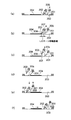
図9は、特許文献1に開示された技術を説明するための一連の工程図であり、それぞれスクリーン印刷装置の要部の側面を示している。
FIG. 9 is a series of process diagrams for explaining the technique disclosed in
図9において、(a)は印刷の終了後にドクター201を下降させた状態を、(b)はペーストの垂れを防止するスキージ202を移動距離Lだけ印刷面204側に移動させた状態を、(c)はコート動作に備えてスキージ202を上昇させた状態を、(d)はコート動作が終了した状態を、(e)は印刷動作に備えてドクター201を上昇させる一方でスキージ202を下降させた状態を、(f)は印刷動作が終了した状態を、それぞれ示す。
9A shows a state where the
特許文献1の技術では、図9(a)に示す印刷終了時の状態から、スキージ202を版面203上に接触させたままで、図9(b)に示すようにスキージ202を版面203に沿って所定距離Lだけ移動させ、印刷面204に近づける。
In the technique of
この時、版面203上のペースト溜まり205の一部はスキージ202に付着した付着ペースト206となり、他の一部はスキージ202により版面203上で延ばされて、付着ペースト206とペースト溜まり205との間を連結する連結部分207となる。
At this time, a part of the
次に、図9(c)に示すようにスキージ202を上昇させると、連結部分207は付着ペースト206に連なるようにスキージ202から垂れ下がる。この際に、連結部分207においてスキージ202側ほど細く切れ易くなるため、スキージ202の上昇直後に垂れ下がっていた連結部分207は、スキージ202側で切れ落ちる。
Next, as shown in FIG. 9C, when the
次に、図9(d)に示すように、ドクター201をコート終了位置まで前進させて、版面203上へのペーストのコート及びペースト返しを行う。
Next, as shown in FIG. 9D, the
次に、図9(e)に示すように、ドクター201を上昇し版面203から離間させる一方で、スキージ202を下降し版面203に当接させる。
Next, as shown in FIG. 9E, the
次に、図9(f)に示すように、スキージ202を印刷終了位置まで移動させて印刷を行う。
Next, as shown in FIG. 9F, printing is performed by moving the
以上の一連の動作のうち、図9(a)から図9(c)に示すように、印刷終了後、スキージ202を版面203上に当接させたままで所定距離Lだけ印刷面側に移動させた後で版面203から離間させることにより、スキージ202に対する付着ペースト206の量を減らすことができる。
Of the series of operations described above, as shown in FIGS. 9A to 9C, after printing is completed, the
よって、付着ペースト206がドクター201によるペースト返し時(図9(c)から図9(d)にかけての動作時)に印刷面204上に垂れ落ちにくくなる。
ところで、一般のスキージ印刷装置の場合、印刷動作とコート動作の間、並びに、コート動作と印刷動作の間に待ち時間が存在する。この待ち時間には、印刷する基板の搬入・搬出という設備面での待ち時間や、ペースト溜りの泡を取り除くなどの目的でコート動作に移るまでの待機時間を意図的に設けるプロセス面での待ち時間や、インライン設備の場合における上流工程からのタクト時間による待ち時間などがある。 In the case of a general squeegee printing apparatus, there is a waiting time between the printing operation and the coating operation and between the coating operation and the printing operation. This waiting time is a waiting time on the process side that intentionally sets a waiting time before moving to the coating operation for the purpose of removing paste bubbles, etc. There are time and waiting time due to tact time from the upstream process in the case of in-line equipment.
特許文献1の技術は、スキージ202に付着したペースト量を減少させることにより、コート動作中にスキージ202から印刷面204上にペーストが垂れるタイミングを遅らせる技術である。
The technique of
このため、印刷終了時からコート動作を開始するまでの待ち時間、すなわち図9(c)の状態からペーストの連結部分が切れ落ちた後の待機時間が長ければ長いほど、版面203から離間し待機状態にあるスキージ202に付着しているペーストが該スキージ202の下部に集中していく。
For this reason, the longer the waiting time from the end of printing to the start of the coating operation, that is, the waiting time after the paste connection part is cut off from the state of FIG. The paste adhering to the
すると、続いて行われるコート動作中に印刷面204にペーストが落下する不具合が発生しやすくなる。
Then, the trouble that the paste falls on the
更に、特許文献1に開示された動作では、ドクター201によるコート動作が完了し、ドクター201が版から離間する時、すなわち図9(e)の動作時に、それまでドクター201の前面に接していたペースト溜まり205のペーストの一部がドクター201に付着する。
Further, in the operation disclosed in
すると、続いてスキージ202により印刷するときに、上昇したままで版面203上を移動するドクター201から、ペーストが版面202上に垂れ落ち、その垂れたペーストを印刷することにより印刷むら不良を発生してしまう。
Then, when the printing is subsequently performed by the
ここで、コート動作後のドクター201(図9(d))についても、特許文献1においてスキージ202が行うのと同様に、所定距離Lだけ印刷面204側に移動する動作を行うことは可能である。
Here, the doctor 201 (FIG. 9D) after the coating operation can also be moved to the
しかしながら、コート動作は、ペーストを版に刷り込む印刷動作とは異なり、ペーストを版になじませる動作であるため、コート動作後にはドクター201の後方においてペーストが版面203上に薄い膜状に広がっている。
However, the coating operation differs from the printing operation in which the paste is imprinted on the plate, so that the paste is applied to the plate. Therefore, after the coating operation, the paste spreads in a thin film shape on the
このため、コート動作後にドクター201が印刷面側に後退動作すれば、広がっているペーストをかき寄せることになり、ドクター201の背面にペースト溜まりが形成されてしまう。
For this reason, if the
さらに、その状態でドクター201を上昇させると、ドクター201の背面にペーストが付着する不具合が生じてしまうため、やはり、続く印刷動作の際にドクター201から版面203上にペーストが垂れてしまう結果、印刷むら不良を起こしてしまう。
Furthermore, if the
つまり、特許文献1においてスキージ202が行うのと同様の動作を、コート動作後のドクター201に適用したとしても、版面202上へのペースト垂れを抑制することは困難である。
That is, even if the same operation as that performed by the
以上のように、特許文献1の技術では、コート動作及び印刷動作の何れの動作の際にも、版面202上へのペーストの垂れ落ちの抑制効果が十分でない。
As described above, the technique disclosed in
また、特許文献1の技術では、コート動作及び印刷動作の何れの動作の際にも、その動作前の待機時間が長くなるほど、ペースト垂れの可能性が増すため、待ち時間を考慮した垂れ防止動作を行う必要があり、そのような待ち時間を考慮した垂れ防止動作ができなければ、ペースト垂れを防止して印刷むら不良の発生を抑えることが困難であった。
Further, in the technique of
本発明は、上記のような問題点を解決するためになされたもので、より好適に版面上へのペーストの垂れ落ちを抑制することができ、好ましくは、印刷動作とコート動作の間、或いは、コート動作と印刷動作の間に生ずる待ち時間に左右されずにペースト垂れを抑制することが可能なスクリーン印刷装置、スキージ駆動装置、ドクター駆動装置、スクリーン印刷方法、その印刷方法を用いたプラズマディスプレイパネルの製造方法、そのプラズマディスプレイパネルを備えるプラズマ表示装置、プログラム及び記録媒体を提供することを目的とする。 The present invention has been made in order to solve the above-described problems, and can more suitably suppress the dripping of the paste on the plate surface. Preferably, it is performed between the printing operation and the coating operation, or Screen printing apparatus, squeegee driving apparatus, doctor driving apparatus, screen printing method, and plasma display using the printing method capable of suppressing paste dripping without being influenced by the waiting time generated between the coating operation and the printing operation It is an object to provide a panel manufacturing method, a plasma display device including the plasma display panel, a program, and a recording medium.
上記課題を解決するため、本発明は、スキージとドクターとスクリーン版とを用いて印刷を行うスクリーン印刷方法において、コート動作の終了位置までの前進を終えた前記ドクターを前記スクリーン版に当接させたままで、第1の距離だけ後退させる後退工程と、前記ドクターを前記スクリーン版に当接させたままで、第2の距離だけ前進させる前進工程と、前記ドクターを前記スクリーン版から離間させる離間工程と、を有し、前記各工程をこの順に行うことを特徴とするスクリーン印刷方法を提供する。 In order to solve the above-described problems, the present invention provides a screen printing method in which printing is performed using a squeegee, a doctor, and a screen plate, and the doctor that has advanced to the end position of the coating operation is brought into contact with the screen plate. A retreating step for retreating by a first distance, a step for advancing by a second distance while keeping the doctor in contact with the screen plate, and a separating step for separating the doctor from the screen plate. The screen printing method is characterized in that the steps are performed in this order.
本発明によれば、コート動作の終了位置までの前進を終えたドクターをスクリーン版に当接させたままで第1の距離だけ後退させる後退制御と、ドクターをスクリーン版に当接させたままで第2の距離だけ前進させる前進制御と、ドクターをスクリーン版から離間させる離間制御と、をこの順に行うので、後退制御と前進制御を行うことによりドクターの前後の面がペースト溜まりに接しない状態とすることができ、その状態でドクターを版から離間させるので、ドクターに付着するペーストの量を極力低減することができ、その後にドクターからペーストが垂れてしまう現象の発生を抑制することができる。 According to the present invention, the retreat control for retreating the doctor who has advanced to the end position of the coating operation by the first distance while being in contact with the screen plate, and the second control with the doctor being in contact with the screen plate. Since the forward control that advances the distance by the distance and the separation control that separates the doctor from the screen plate are performed in this order, the front and back surfaces of the doctor are not in contact with the paste pool by performing the backward control and the forward control. In this state, the doctor is separated from the plate, so that the amount of paste adhering to the doctor can be reduced as much as possible, and the occurrence of the phenomenon of the paste dripping after that can be suppressed.
よって、印刷動作中にドクターが印刷面の上方を移動する際に、ドクターから印刷面にペーストが垂れてしまうことを抑制でき、印刷むら不良の発生も抑制できる。 Therefore, when the doctor moves above the printing surface during the printing operation, it is possible to suppress the paste from dripping from the doctor to the printing surface, and it is possible to suppress the occurrence of uneven printing.
更に、これらのペースト垂れ抑制動作を組み合わせることによって、スキージから印刷面にペーストが落下してしまうことと、ドクターから印刷面にペーストが落下してしまうこと、を共に抑制することができ、より好適に印刷むら不良の発生を抑制できる。 Furthermore, by combining these paste dripping suppression operations, it is possible to suppress both the drop of the paste from the squeegee onto the printing surface and the drop of the paste from the doctor onto the printing surface, which is more preferable. In addition, the occurrence of uneven printing can be suppressed.
なお、何れのペースト垂れ抑制動作も、印刷動作・コート動作間の待機時間に左右されないため、安定した品質を得ることができる。 In addition, since any paste dripping suppression operation is not influenced by the standby time between the printing operation and the coating operation, stable quality can be obtained.
加えて、本発明は、スキージやドクターの動作制御を行うための制御プログラムを変更するだけで実現することができるため、印刷装置の構造は変更する必要がなく、安価にペースト垂れを抑制できると共に、印刷装置のメンテナンス性が悪化することもない。 In addition, since the present invention can be realized only by changing the control program for controlling the operation of the squeegee and the doctor, there is no need to change the structure of the printing apparatus, and paste dripping can be suppressed at a low cost. The maintainability of the printing apparatus is not deteriorated.
以下、図面を参照して、本発明に係る実施形態について説明する。 Embodiments according to the present invention will be described below with reference to the drawings.
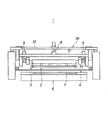
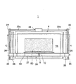
図3は本実施形態に係るスクリーン印刷方法を実施するスクリーン印刷装置の主要部を示す正面図、図4は図3のスクリーン印刷装置の平面図である。 FIG. 3 is a front view showing a main part of the screen printing apparatus for performing the screen printing method according to the present embodiment, and FIG. 4 is a plan view of the screen printing apparatus of FIG.
図3及び図4に示すように、本実施形態に係るスクリーン印刷方法を実施するスクリーン印刷装置1は、印刷動作を行うスキージ2(図3)と、コート動作を行うドクター3(図3)と、スクリーン版4と、被印刷物として例示する基板7(図3)を上面に支持するテーブル5(図3)と、スキージ2及びドクター3を前後動作及び昇降動作させる駆動機構(後述)と、を備えている。
As shown in FIGS. 3 and 4, the
なお、基板7は、例えば、後述するプラズマディスプレイパネルの前面基板10或いは背面基板20である。
The substrate 7 is, for example, a
スキージ2及びドクター3は、例えばゴム或いはゴムに類似した弾力性を有する材質からなり、図3及び図4における左右方向に長尺な板状に構成され、駆動機構によりテーブル5の上方位置において保持されている。
The
なお、ドクター3は、コート動作時の余分なペーストを該ドクター3の前側に掻き集めることができるように、両端部が前側に向けて屈曲している(図1、図2参照)。
Note that the
スクリーン印刷装置1の駆動機構において、スキージ2及びドクター3を昇降動作させる機構部は、スキージ昇降用シリンダ8と、ドクター昇降用シリンダ10(図4)と、を備えて構成されている。
In the drive mechanism of the
スキージ2は、スキージ昇降用シリンダ8によって、スクリーン版4の版面4aに対し近接・離間する上下方向へ往復移動可能に支持され、該スキージ昇降用シリンダ8により下降されることによって版面4a上に当接可能となっている。
The
同様に、ドクター3は、ドクター昇降用シリンダ10によって、スクリーン版4の版面4aに対し近接・離間する上下方向へ往復移動可能に支持され、該ドクター昇降用シリンダ10により下降されることによって版面4a上に当接可能となっている。
Similarly, the
また、駆動機構は、図3に示すように、スキージ2及びドクター3をスクリーン版4の上方位置に保持したバー31を備えている。なお、図3において、ドクター2はスキージ1の後側に位置し、その両端部を除いてスキージ1に隠れている。
As shown in FIG. 3, the drive mechanism includes a
また、駆動機構は、バー31の左右に設置された平行調整用の一対のモータ9を備えている。
The drive mechanism also includes a pair of
この一対のモータ9を駆動させてスキージ2及びドクター3の左右両端の鉛直位置を調節することにより、印刷テーブル5の上面に対するスキージ2及びドクター3の平行を出す(調整する)ことができる。
By driving the pair of
更に、平行調整用の一対のモータ9の駆動量を調節することにより、版面4aに対するスキージ2及びドクター3の押し込み量を任意に設定することができる。
Further, by adjusting the drive amount of the pair of
また、駆動機構において、スキージ2及びドクター3を前後動作させる機構部は、図4に示すように、例えばサーボモータからなり正逆回転が可能な走行用モータ33と、この走行用モータ33の左右の駆動軸33aの先端にそれぞれ連結された左右一対のプーリ34と、このプーリ34の各々と対をなす左右一対のプーリ35と、これら2組のプーリ34,35間に各々架け渡された左右一対のタイミングベルト36と、この一対のタイミングベルト36の回転に伴い前後方向(図4の矢印G、矢印H方向で、且つ、テーブル5の上面に沿う方向)に走行する走行バー37と、この走行バー37を前後方向にガイドする一対のLMガイド38と、を備えて構成されている。
Further, in the drive mechanism, as shown in FIG. 4, the mechanism unit that moves the
このうち一対のLMガイド38は長尺に構成され、各々の長手方向が前後方向となるように、テーブル5の左右両脇にそれぞれ配置されている。また、プーリ34、35はLMガイド38の両端位置に配置され、走行バー37はテーブル5の上方に配置されている。
Of these, the pair of LM guides 38 is formed in a long shape, and is arranged on both the left and right sides of the table 5 so that the longitudinal direction thereof is the front-rear direction. Further, the
ここで、走行バー37は、スキージ2、ドクター3、それらを保持したバー31、平行調整用の一対のモータ9、スキージ昇降用シリンダ8、ドクター昇降用シリンダ10を含むスキージユニット39を支持している。
Here, the traveling
従って、走行用モータ33の駆動により走行バー37が前後方向に移動する際には、スキージユニット39も走行バー37に伴って前後方向に一体的に移動することになる。
Therefore, when the
また、上記のように、スキージ2とドクター3とは、相互に独立に駆動するスキージ昇降用シリンダ8とドクター昇降用シリンダ10とにより、相互に独立に昇降動作可能となっている。
Further, as described above, the
よって、スキージ2とドクター3のうちスキージ2のみを下降させてスクリーン版4の版面4aに当接させた状態で、スキージユニット39を移動させることにより、スキージ2による印刷動作を行うことができる一方で、スキージ2とドクター3のうちドクター3のみを下降させてスクリーン版4の版面4aに当接させた状態で、スキージユニット39を移動させることにより、ドクター3によるコート動作をことができる(詳細後述)。
Therefore, the printing operation by the
また、印刷テーブル5の上面には図示しない吸着穴が形成され、被印刷物である基板7を印刷テーブル5上に位置決めした状態で、この吸着穴を介して真空ポンプ又はブロアによる吸引を行うことにより、基板7をテーブル5上に固定することができる。 Further, a suction hole (not shown) is formed on the upper surface of the printing table 5, and suction is performed by a vacuum pump or a blower through the suction hole in a state where the substrate 7 as a printing object is positioned on the printing table 5. The substrate 7 can be fixed on the table 5.
さらに、このテーブル5上にはスクリーン版4が配設されており、その版面4aが基板7上に重ね合わされるようになっている。また、版面4a上には、印刷面60(図4)が設けられている。
Further, a
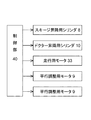
図5は、スクリーン印刷装置1の主要な制御ブロック図である。
FIG. 5 is a main control block diagram of the
図5に示すように、スクリーン印刷装置1は、各構成要素を統括的に制御する制御部40を備えている。
As shown in FIG. 5, the
この制御部40は、例えば、CPU、ROM、RAMなどを備えて構成され、このうちCPUは制御動作を実行し、ROMにはCPUの制御プログラムなどが記録され、RAMはCPUの作業領域などとして機能する。
The
そして、制御部40は、制御プログラムに従って、スキージ昇降用シリンダ8、ドクター昇降用シリンダ10、走行用モータ33、一対の平行調整用モータ9などに対して、それぞれ制御信号を出力し、これらアクチュエータ類の動作制御を行う。
Then, the
この動作制御により、スキージ2及びドクター3の昇降動作、前後動作、平行だし動作、及び、押し込み量の設定動作などが制御される。
By this operation control, the raising / lowering operation of the
次に、上記のように構成されたスクリーン印刷装置1を用いたスクリーン印刷方法について説明する。
Next, a screen printing method using the
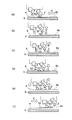
図1及び図2は、本実施形態に係るスクリーン印刷方法における一連の動作を説明するためのスクリーン印刷装置1の主要部を示す側面図である。
1 and 2 are side views showing a main part of the
このうち図1には印刷動作終了時からコート動作実行中までの状態を示す一方で、図2にはコート動作終了時から印刷動作実行中までの状態を示しており、図1及び図2に示す一連の動作が1回の印刷のサイクルとなっている。従って、図1及び図2に示す動作を交互に繰り返すことにより、印刷を繰り返し行うことができる。 Among these, FIG. 1 shows a state from the end of the printing operation to the execution of the coating operation, while FIG. 2 shows a state from the end of the coating operation to the execution of the printing operation. A series of operations shown is a single printing cycle. Therefore, printing can be repeatedly performed by alternately repeating the operations shown in FIGS.
ここで、図1に示す一連の動作を行うことにより、コート動作中におけるスキージ2からのペーストの垂れを抑制することができ、図2に示す一連の動作を行うことにより、印刷動作中におけるドクター3からのペーストの垂れを抑制することができる。
Here, by performing the series of operations shown in FIG. 1, dripping of the paste from the
先ず、図1を参照して、コート動作中におけるスキージ2からのペーストの垂れを抑制するための動作を説明する。
First, with reference to FIG. 1, the operation for suppressing the dripping of the paste from the
なお、以下に説明する動作は、制御部40の制御下で、スクリーン印刷装置1が自動的に行う。
The operation described below is automatically performed by the
図1において、(a)はスキージ2による印刷動作が終了した状態を、(b)はスキージ2をスクリーン版4の版面4aから離間させた状態を、(c)はスキージ2を印刷面60(図示略)側に移動させた状態を、(d)はスキージ2を版面4aに再度当接させた状態を、(e)はスキージ2を版面4aから再度離間させる一方でドクター3を版面4aに当接させた状態を、(f)はドクター3によるコート動作を行う状態を、それぞれ示す。
1A shows a state in which the printing operation by the
すなわち、図1(a)は、スキージ2が版面4aに当接した状態のままで矢印A方向に印刷終了位置まで前進し、印刷動作を終えた状態を示す。
In other words, FIG. 1A shows a state in which the
ここで、印刷終了位置は、印刷面60(図1では図示略)から矢印A方向に100mm以上離れていることが望ましい。 Here, the print end position is preferably 100 mm or more away from the print surface 60 (not shown in FIG. 1) in the direction of arrow A.
この段階では、スキージ2が版面4aに沿って矢印A方向に移動したことにより、版面4a上において、スキージ2の前側に接する位置にペースト溜まり50が形成されている。
At this stage, since the
続いて、スキージ2は、図1(a)の状態で所定時間待機した後で、版面4aに対し垂直方向に上昇し、版面4aから離間する(図1(b))。
Subsequently, after waiting for a predetermined time in the state of FIG. 1A, the
ここで、図1(a)の段階でスキージ2の前側に存在するペースト溜まり50のペーストの一部は、図1(b)の動作でスキージ2が版面4aから離間する際に、スキージ2に付着した付着ペースト51となる。
Here, a part of the paste in the
続いて、図1(a)の状態に至る印刷動作により既に印刷がなされた基板7はテーブル5上から搬出され、次に印刷される基板7が新たにテーブル5上に搬入・位置決めされることにより、ドクター3によるコート動作の開始準備がなされる。
Subsequently, the substrate 7 that has already been printed by the printing operation leading to the state of FIG. 1A is carried out from the table 5, and the next printed substrate 7 is newly carried and positioned on the table 5. Thus, preparation for starting the coating operation by the
この開始準備が整うまでの間の所定時間、スキージ2は、図1(b)の状態で待機する。なお、図1では基板7の図示を省略している。
The
このように待機状態となっている間、スキージ2の付着ペースト51は時間経過に伴いスキージ2の下部に収集していき、最終的には版面4a上に垂れる。よって、スキージ2の付着ペースト51の量が減少する。
During the standby state in this way, the adhered
ドクター3によるコート動作の開始準備が整うと、該コート動作を開始する直前に、図1(b)の状態から図1(c)に示すように、スキージ2を印刷面60側に向けて矢印B方向、すなわち、例えば印刷動作方向とは反対方向に所定距離L1だけ移動させる。
When preparation for the start of the coating operation by the
この移動は、版面4a上においてペースト溜まり50が無い部位の上方にスキージ2を移動させるためのものであり、本実施形態の場合、例えば、ペースト溜まり50と印刷面60との間の部位の上方位置への移動としている。なお、距離L1は、例えば、50mm〜70mmである。
This movement is for moving the
続いて、図1(d)に示すように、スキージ2を版面4aに対し垂直に下降させ、該版面4a上に当接させる。
Subsequently, as shown in FIG. 1D, the
ここで、スキージ2の下降圧、すなわち版面4aに対するスキージ2の接触圧は、印刷動作時における下降圧(接触圧)とは、スキージ昇降シリンダ8の駆動量を調節することによって、相互に異なる値に設定できる。
Here, the lower pressure drop of the
ここでの下降圧は、スキージ2を下降させ、且つ、版面4a上に当接するのに十分な圧力を設定すればよい為、印刷時の常用圧より小さい下降圧を設定する。
Here, the lower pressure drop is set to a pressure lower than the normal pressure at the time of printing because it is sufficient to set a pressure sufficient to lower the
また、平行調整用の一対のモータ9の駆動を調節することにより、版面4aに対するスキージ2の押し込み量が所要の値に設定されているが、スクリーン版4の下方にはテーブル5が位置しており、印刷動作時と同様にスキージ2からスクリーン版4への押し込み力は、テーブル5により支持される。
Further, by adjusting the driving of the pair of
これらのことから、図1(d)に示すスキージ2の当接動作の際の版4への負荷は抑制される。
For these reasons, the load on the
図1(d)の当接動作により、スキージ2は、版面4a上においてペースト溜まり50が存在しない部位に当接するため、スキージ2の前面や下部の付着ペースト51は版4に再付着する。
1 (d), the
続いて、図1(e)に示すように、スキージ2を再度、版面4aに対し垂直に上昇させて版面4aから離間させ、その一方で、ドクター3を下降させて版面4a上に当接させる。
Subsequently, as shown in FIG. 1 (e), the
この段階でも、スキージ2には付着ペースト51が付着したままとなるが、図1(d)の当接動作により付着ペースト51の一部は版面4aに付着した版面側付着ペースト52となっている。
Even at this stage, the adhered
このため、図1(e)の段階でのスキージ2の付着ペースト51の量は、版面側付着ペースト52の分だけ、図1(c)の段階よりも少なくなる。
For this reason, the amount of the
続いて、図1(f)に示すように、ドクター3を矢印C方向に移動させて、版面4a上へのペーストのコート動作を行い、版面4a上に薄くペースト膜53を形成する。
Subsequently, as shown in FIG. 1 (f), the
このコート動作の際、スキージ2は、印刷面60(図示略)の上方を矢印C方向に通過するが、上記のように図1(a)〜図1(f)の一連の動作を行う結果として、スキージ2の付着ペースト51の量が低減されているため、該コート動作中にスキージ2からペーストが垂れる現象は起こりにくい。
During this coating operation, the
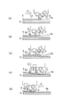
次に、図2を参照して、印刷動作中におけるドクター3からのペーストの垂れを抑制するための動作を説明する。
Next, with reference to FIG. 2, the operation for suppressing the dripping of the paste from the
図2において、(a)は図1(f)で説明したコート動作が終了した状態を、(b)はドクター3をコート動作とは反対方向(印刷面60側)に移動させた状態を、(c)はドクター3を再びコート動作方向に移動させた状態を、(d)はドクター3を版面4aから離間させた状態を、(e)はスキージ2による印刷動作を行う状態を、それぞれ示す。
2, (a) shows a state where the coating operation described in FIG. 1 (f) has been completed, (b) shows a state where the
図2(a)に示すように、ドクター3が下降し版面4aに当接した状態でコート終了位置まで移動した状態では、版面4a上においてドクター3の後方にはペースト膜53が形成されている一方で、ドクター3の前にはペースト溜まり50が形成されている。
As shown in FIG. 2A, in the state where the
次に、ドクター3は、版面4aに当接したままで、印刷動作の準備が整うまで(基板7の位置決めが完了するまで)待機する。ドクター3が版面4aに当接した状態で待機する理由は、ペーストの印刷面60側への侵入を防ぐためである。
Next, the
印刷動作の開始準備が整うと、該印刷動作を開始する直前に、図2(b)に示すように、ドクター3を版面4a上に当接させたままで、コート動作時よりも低速で距離L2だけ印刷面60側(矢印D方向)に後退させる。
When preparation for starting the printing operation is completed, immediately before starting the printing operation, as shown in FIG. 2 (b), the
この後退動作により、ドクター3はその前側にあるペースト溜まり50から離間する。
By this backward movement, the
また、この後退動作の際に、ドクター3の前面に付着しているペーストは、版面4a上で延ばされるとともに版面4a上にすり付けられるため、ドクター3前面におけるペーストの付着量は減少する。
Further, during this backward movement, the paste adhering to the front surface of the
なお、距離L2は、ドクター3が印刷面60までは後退しないが、ドクター3をペースト溜まり50から離間させ、ドクター3前面のペースト付着量を減少させるのに十分なだけの距離である。
Note that the distance L2 is a distance that is sufficient for the
ここで、ドクター3の後方にはペースト膜53が形成されているため、この後退動作の際に、ドクター3の背面側にはペースト溜まり55が新たに形成され、ドクター3の背面側にペーストが付着する。
Here, since the
そのため、続いて、ドクター3背面側のペースト付着量を少なくするため、図2(c)に示すように、再度、ドクター3をコート動作と同方向(矢印E方向)に距離L3だけ前進させる。
Therefore, subsequently, in order to reduce the paste adhesion amount on the back side of the
この前進動作により、ドクター3は背面側のペースト溜まり55から離間する。
By this forward movement, the
また、この前進動作の際に、ドクター3の背面に付着しているペーストは、版面4a上で延ばされるとともに版面4a上にすり付けられるため、ドクター3背面におけるペーストの付着量は減少する。
Further, during this forward movement, the paste adhering to the back surface of the
すなわち、この段階で、ドクター3の前面及び背面へのペースト付着量は共に少ない状態である。
That is, at this stage, the amount of paste attached to the front surface and the back surface of the
なお、距離L3は、距離L2よりも小さい方が望ましい。なぜならば、L3≧L2にしてしまうと、ドクター3の前面が再びペースト溜まり50に接してしまうからである。
The distance L3 is desirably smaller than the distance L2. This is because if L3 ≧ L2, the front surface of the
続いて、図2(d)に示すように、ドクター3を版面4aに対し垂直に上昇させ、版面4aから離間させる、その一方で、スキージ2を版面4aに対し垂直に下降させ、版面4a上に当接させる。
Subsequently, as shown in FIG. 2 (d), the
続いて、図2(e)に示すように、スキージ2を版面4aに当接させた状態のままで、該スキージ2を矢印F方向に移動させて、ペーストを基板7に刷り込むことにより、印刷動作を行う。なお、図2(e)の状態では、ペースト溜まり50がペースト溜まり55を呑み込んで、これと一体化している。
Subsequently, as shown in FIG. 2E, the
この図2(f)の印刷動作の際、ドクター3は、印刷面60(図示略)の上方を矢印F方向に通過するが、上記のように図2(b)〜図2(d)の一連の動作を行う結果として、ドクター3へのペーストの付着量が低減されているため、該印刷動作中にドクター3からペーストが垂れる現象は起こりにくい。
During the printing operation of FIG. 2 (f), the
以上のように、印刷動作中にドクター3から印刷面60上にペーストが垂れてしまうことと、コート動作中にスキージ2から印刷面60上にペーストが垂れてしまうことと、が抑制されるため、印刷むら不良が極力発生しにくいこととなる。
As described above, the dripping of the paste from the
次に、図6及び図7を参照して、本実施形態に係るスクリーン印刷方法による被印刷物の具体例としての基板を備えるプラズマディスプレイパネルと、このプラズマディスプレイパネルの製造方法について説明する。 Next, with reference to FIG.6 and FIG.7, the plasma display panel provided with the board | substrate as a specific example of the to-be-printed material by the screen printing method which concerns on this embodiment, and the manufacturing method of this plasma display panel are demonstrated.
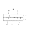
図6は本実施形態に係るスクリーン印刷方法によりバス電極14を形成したプラズマディスプレイパネルの前面基板10を示している。
FIG. 6 shows the
図6に示すように、ガラス基板11上に走査電極12及び維持電極13を形成した後、本実施形態に係るスクリーン印刷方法により、走査電極12上及び維持電極13上にバス電極14をパターン形成する。その後、走査電極12、維持電極13及びバス電極14を覆うようにしてガラス基板11上に透明誘電体層15を形成し、更に、該透明誘電体層15を覆う表面保護層16を形成し、プラズマディスプレイパネルの前面基板10を作製する。
As shown in FIG. 6, after forming the
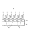
図7は本実施形態に係るスクリーン印刷方法によりアドレス電極22を形成したプラズマディスプレイパネルの背面基板20を示している。
FIG. 7 shows the
図7に示すように、ガラス基板21上に、本実施形態に係るスクリーン印刷方法によりアドレス電極22をパターン形成し、その後、アドレス電極22を覆うようにガラス基板21上に白色誘電体層23を形成する。更に、白色誘電体層23上に隔壁24を形成し、隔壁24により区画される空間内に蛍光体層25を形成し、プラズマディスプレイパネルの背面基板20を作製する。
As shown in FIG. 7, the
更に、上記のように作製された前面基板10及び背面基板20を相互に接合してプラズマディスプレイパネルを製造する。
Further, the
このように製造されたプラズマディスプレイパネルは、前面基板10におけるバス電極14のパターン形成と、背面基板20におけるアドレス電極22のパターン形成と、に本実施形態に係るスクリーン印刷方法を用いているため、印刷むら不良が少なく、高品質のプラズマディスプレイパネルとすることができる。
Since the plasma display panel manufactured in this way uses the screen printing method according to this embodiment for pattern formation of the
次に、図8を参照して、以上のようにして製造されたプラズマディスプレイパネルを備えて構成されるプラズマ表示装置の好適な一例について説明する。 Next, with reference to FIG. 8, a preferred example of a plasma display device including the plasma display panel manufactured as described above will be described.
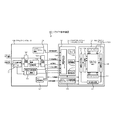
図8は、本実施形態に係るプラズマ表示装置の好適な一例を示す概略的なブロック図である。 FIG. 8 is a schematic block diagram showing a preferred example of the plasma display device according to the present embodiment.
図8に示すプラズマ表示装置100は、アナログインタフェース120と、PDPモジュール130とを備えて概略構成されている。 The plasma display device 100 shown in FIG. 8 is schematically configured to include an analog interface 120 and a PDP module 130.
PDPモジュール130は、上記のようにして製造されたプラズマディスプレイパネル150(以下、PDP150)を備えている。 The PDP module 130 includes a plasma display panel 150 (hereinafter referred to as “PDP 150”) manufactured as described above.
アナログインタフェース120は、クロマ・デコーダを備えたY/C分離回路121と、A/D変換回路122と、PLL回路を備えた同期信号制御回路123と、画像フォーマット変換回路124と、逆γ(ガンマ)変換回路125と、システム・コントロール回路126と、PLE制御回路127とを備えて構成されている。
The analog interface 120 includes a Y /
アナログインタフェース120は、概略的には、受信したアナログ映像信号をディジタル信号に変換したのち、これをPDPモジュール130に供給する機能を有している。 In general, the analog interface 120 has a function of converting a received analog video signal into a digital signal and supplying the digital signal to the PDP module 130.
例えばテレビチューナーから入力されるアナログ映像信号は、Y/C分離回路121において、R(赤),G(緑)、B(青)の各色の輝度信号に分解されたのち、A/D変換回路122においてディジタル信号に変換される。
For example, an analog video signal input from a TV tuner is decomposed into luminance signals of R (red), G (green), and B (blue) in the Y /
その後、PDPモジュール130の画素構成と映像信号の画素構成とが相互に異なる場合には、画像フォーマット変換回路124において、必要な画像フォーマットの変換処理が行われる。
Thereafter, when the pixel configuration of the PDP module 130 and the pixel configuration of the video signal are different from each other, the image
A/D変換回路122において、映像信号のA/D(アナログ/ディジタル)変換を行ったのち、逆γ変換回路125において、映像信号に対して逆γ変換を施して、線形特性に復元されたディジタル映像信号を生成する。このようにして生成されたディジタル映像信号は、RGB映像信号として、PDPモジュール130に出力される。
The A /
同期信号制御回路123に内蔵されているPLL(位相同期ループ)回路は、アナログ映像信号と同時に供給される水平同期信号を基準として、サンプリングクロック信号およびデータクロック信号を生成して、PDPモジュール130に出力する。
A PLL (phase-locked loop) circuit built in the synchronizing
アナログインタフェース120のPLE制御回路127は、PDPの輝度制御を行う。具体的には、平均輝度レベルが所定値以下である場合には表示輝度を上昇させ、平均輝度レベルが所定値を超える場合には、表示輝度を低下させるように制御する。
The
システム・コントロール回路126は、PDPモジュール130に対して、各種制御信号を出力する。
The
PDPモジュール130は、ディジタル信号処理・制御回路131と、パネル部132と、DC/DCコンバータを内蔵するモジュール内電源回路133とから構成されている。ディジタル信号処理・制御回路131は、入力インタフェース信号処理回路134と、フレームメモリ135と、メモリ制御回路136と、ドライバ制御回路137とを含んでいる。
The PDP module 130 includes a digital signal processing / control circuit 131, a panel unit 132, and an in-module
入力インタフェース信号処理回路134は、システム・コントロール回路126から発信される各種制御信号、逆γ変換回路125から発信されるRGB映像信号、同期信号制御回路123から発信される同期信号、PLL回路から発信されるデータクロック信号を受信する。
The input interface
入力インタフェース信号処理回路134に入力された映像信号の平均輝度レベルは、入力インタフェース信号処理回路134内の入力信号平均輝度レベル演算回路(図示略)によって計算されて、例えば5ビットデータとして出力される。また、PLE制御回路127は、平均輝度レベルに応じてPLE制御データを設定して、入力インタフェース信号処理回路134内の輝度レベル制御回路(図示略)に供給する。
The average luminance level of the video signal input to the input interface
ディジタル信号処理・制御回路131では、入力インタフェース信号処理回路134において、これらの各種信号の処理を行ったのち、制御信号をパネル部132に送信する。これと同時に、メモリ制御回路136はメモリ制御信号を、ドライバ制御回路137はドライバ制御信号を、それぞれパネル部132に送信する。
In the digital signal processing / control circuit 131, these various signals are processed in the input interface
パネル部132は、PDP150と、PDP150の走査電極を駆動する走査ドライバ138と、PDP150のデータ電極を駆動するデータドライバ139と、PDP150および走査ドライバ138にパルス電圧を供給する高圧パルス回路140と、高圧パルス回路140からの余剰電力を回収する電力回収回路141とを備えて構成されている。
The panel unit 132 includes a PDP 150, a
PDP150は、例えば1365個×768個に配列された画素を有するものとして構成されている。PDP150においては、走査ドライバ138が走査電極を制御し、データドライバ139がデータ電極(アドレス電極)を制御することによって、これらの画素のうちの所定の画素の点灯または非点灯が制御されて、所望の画像表示が行われる。
The PDP 150 is configured to have pixels arranged in, for example, 1365 × 768. In the PDP 150, the
このようなプラズマ表示装置100は、上記のように、本実施形態に係るスクリーン印刷方法を用いて製造されたプラズマディスプレイパネル150を備えているため、該プラズマディスプレイパネル150における印刷むら不良が少なく、高品質のプラズマ表示装置とすることができる。 Since the plasma display device 100 includes the plasma display panel 150 manufactured using the screen printing method according to the present embodiment as described above, there is little printing unevenness in the plasma display panel 150, A high-quality plasma display device can be obtained.
以上のような実施形態によれば、図1を参照して上記に説明したように、コート動作中のスキージ2からのペースト垂れの原因であるスキージ2への付着ペースト51を、コート開始直前に再度、スクリーン版4の版面4a上においてペースト溜まり50の無い面に当接させることにより、版面4aに再付着させた後で、スキージ2を再度、版面4aから離間させるので、該離間後におけるスキージ2に対する付着ペースト51の量を減少させることができる。更に、その直後にコート動作をおこなう為、コート動作中においてスキージ2から印刷面60へとペーストが垂れてしまうことを好適に抑制することができる。
According to the embodiment as described above, as described above with reference to FIG. 1, the
また、図2を参照して上記に説明したように、ドクター3が版4から離間する直前にドクター3の前後の面がペースト溜まり50、55に接しないようにドクター3を前進・後退移動することにより、印刷動作中のドクター3からのペースト垂れの原因となるドクター3への付着ペーストの量を極力抑えるようにでき、その直後に印刷動作をおこなう為、印刷動作中においてドクター3から印刷面60へとペーストが垂れてしまうことを好適に抑制することができる。
Further, as described above with reference to FIG. 2, the
また、図1、図2で説明したいずれのペースト垂れ抑制動作も、印刷動作・コート動作間の待機時間に左右されないため、安定した品質を得ることができる。 In addition, any paste dripping suppression operation described with reference to FIGS. 1 and 2 is not affected by the standby time between the printing operation and the coating operation, so that stable quality can be obtained.
加えて、本実施形態の動作は、従来のスクリーン印刷装置において、スキージ2やドクター3の動作制御を行うための制御プログラムのみを変更するだけで実現することができるため、印刷装置の構造は変更する必要がなく、安価にペースト垂れを抑制できると共に、印刷装置のメンテナンス性が悪化することもない。
In addition, since the operation of the present embodiment can be realized by changing only the control program for controlling the operation of the
なお、上記の実施形態では、コート動作中にスキージ2から印刷面60上にペーストが垂れてしまうことを抑制する図1の動作と、印刷動作中にドクター3から印刷面60上にペーストが垂れてしまうことを抑制する図2の動作と、を共に行う例を説明したが、本発明はこの例に限らず、何れか一方のみを行うだけでも印刷むらを抑制する効果が得られる。
In the above embodiment, the paste shown in FIG. 1 prevents the paste from dripping from the
また、上記の実施形態では、図1(c)の動作において、スキージ2を印刷動作方向とは反対方向に所定距離L1だけ移動させる例について説明したが、図1(c)の段階でのスキージ2の移動方向は、その反対方向であっても良く、要は、その後の再当接動作(図1(d))の際に、スキージ2を版面4a上においてペースト溜まり50の無い部位に当接させることができるような移動を行えばよい。ただし、スキージ2を図1(c)とは反対方向に移動させる場合、スキージ2がペースト溜まり50を超える必要があるため、上記の実施形態において説明した例と比べると、必要な移動距離が長くなる。
In the above embodiment, the example in which the
また、上記の実施形態では、図1(b)の段階で、スキージ2を版面4aに対し垂直に上昇させる例を説明したが、本発明はこの例に限らず、スキージ2を版面4aから離間させつつ図1の矢印B方向又はその反対方向に移動させて、スキージ2をスクリーン版4上において印刷動作の終了位置から印刷動作方向又はその反対方向に所定距離だけ離れた部位の上方位置へと移動させるようにしても良い。
In the above-described embodiment, the example in which the
また、上記の実施形態では、スキージ2とドクター3とを備えるスクリーン印刷装置1及びその印刷装置1を用いたスクリーン印刷方法について説明したが、ドクター3を備えていないスクリーン印刷装置及びその印刷装置を用いた印刷方法にも、図3の動作を適用してペーストの垂れを抑制することが可能である。
In the above embodiment, the
1 スクリーン印刷装置
2 スキージ
3 ドクター
4 版(スクリーン版)
4a 版面
50 ペースト溜まり
55 ペースト溜まり
60 印刷面
A 印刷動作方向
B 印刷動作の反対方向
C コート動作方向
D ドクターが後退する方向
E ドクターが前進する方向
1
Claims (1)
コート動作の終了位置までの前進を終えた前記ドクターを前記スクリーン版に当接させたままで、第1の距離だけ後退させる後退工程と、
前記ドクターを前記スクリーン版に当接させたままで、第2の距離だけ前進させる前進工程と、
前記ドクターを前記スクリーン版から離間させる離間工程と、
を有し、前記各工程をこの順に行うことを特徴とするスクリーン印刷方法。 In a screen printing method for printing using a squeegee, a doctor and a screen plate ,
The doctor has completed the advance of the end position of the coating operation while brought into contact with the screen plate, the retraction step of retracting a first distance,
While the doctor is brought into contact with the screen plate, a forward step of advancing by a second distance,
A separation step of separating the doctor from the screen plate;
A screen printing method , wherein the steps are performed in this order .
Priority Applications (1)
| Application Number | Priority Date | Filing Date | Title |
|---|---|---|---|
| JP2004263789A JP4477458B2 (en) | 2004-09-10 | 2004-09-10 | Screen printing method |
Applications Claiming Priority (1)
| Application Number | Priority Date | Filing Date | Title |
|---|---|---|---|
| JP2004263789A JP4477458B2 (en) | 2004-09-10 | 2004-09-10 | Screen printing method |
Publications (2)
| Publication Number | Publication Date |
|---|---|
| JP2006076183A JP2006076183A (en) | 2006-03-23 |
| JP4477458B2 true JP4477458B2 (en) | 2010-06-09 |
Family
ID=36156035
Family Applications (1)
| Application Number | Title | Priority Date | Filing Date |
|---|---|---|---|
| JP2004263789A Expired - Fee Related JP4477458B2 (en) | 2004-09-10 | 2004-09-10 | Screen printing method |
Country Status (1)
| Country | Link |
|---|---|
| JP (1) | JP4477458B2 (en) |
Families Citing this family (2)
| Publication number | Priority date | Publication date | Assignee | Title |
|---|---|---|---|---|
| JP2017087596A (en) * | 2015-11-11 | 2017-05-25 | トッパン・フォームズ株式会社 | Printing method and printing machine |
| JP2023161610A (en) * | 2022-04-26 | 2023-11-08 | 株式会社Fuji | Printing device and method of controlling the printing device |
-
2004
- 2004-09-10 JP JP2004263789A patent/JP4477458B2/en not_active Expired - Fee Related
Also Published As
| Publication number | Publication date |
|---|---|
| JP2006076183A (en) | 2006-03-23 |
Similar Documents
| Publication | Publication Date | Title |
|---|---|---|
| JP6089228B2 (en) | Screen printing apparatus, electronic component mounting system, and screen printing method | |
| JP5919480B2 (en) | Screen printer and screen mask cleaning device | |
| US20110252988A1 (en) | Screen printing apparatus and screen painting method | |
| US20030188645A1 (en) | Screen printing method | |
| CN114222664B (en) | Display board side terminal printing system | |
| JP2009154304A (en) | Screen printing apparatus and screen printing method | |
| JP2015003517A (en) | Cleaning assembly for removing paste material in printer and cleaning method | |
| JPWO2018096607A1 (en) | Screen printing machine | |
| JP4477458B2 (en) | Screen printing method | |
| JP2004223788A (en) | Squeegee and screen printing machine | |
| JP3293409B2 (en) | Method for managing viscosity of cream solder in screen printing equipment | |
| JP4432499B2 (en) | Screen printing apparatus and screen printing method | |
| JP5360442B2 (en) | Screen printing frame and electronic device manufacturing method | |
| KR101037604B1 (en) | Embossed stamping offset printing apparatus and printing system, and embossed stamping offset printing method | |
| JP5519482B2 (en) | Screen printing apparatus and screen printing method | |
| JP2009137218A (en) | Screen printing device | |
| JP2007185934A (en) | Cleaning mechanism of screen, screen printer, cleaning method of screen, screen printing method, manufacturing process of plasma display panel, and manufacturing process of plasma display | |
| JP2006088709A (en) | Screen printing method and screen printing apparatus | |
| JP4258267B2 (en) | Cream solder printing machine | |
| JP3835931B2 (en) | Printing paste printing method and apparatus | |
| CN108290408A (en) | The control method of solder printing machine and solder printing machine | |
| JP6824880B2 (en) | Printing equipment | |
| JPH06336006A (en) | Screen printing method and printer and printing action control system used in the method | |
| JPH10157062A (en) | Screen printing apparatus and screen printing method | |
| KR20220109498A (en) | Screen Tilting Structure Of Screen Printer |
Legal Events
| Date | Code | Title | Description |
|---|---|---|---|
| A621 | Written request for application examination |
Free format text: JAPANESE INTERMEDIATE CODE: A621 Effective date: 20070803 |
|
| A711 | Notification of change in applicant |
Free format text: JAPANESE INTERMEDIATE CODE: A711 Effective date: 20090608 |
|
| A977 | Report on retrieval |
Free format text: JAPANESE INTERMEDIATE CODE: A971007 Effective date: 20091116 |
|
| A131 | Notification of reasons for refusal |
Free format text: JAPANESE INTERMEDIATE CODE: A131 Effective date: 20091124 |
|
| A521 | Written amendment |
Free format text: JAPANESE INTERMEDIATE CODE: A523 Effective date: 20100107 |
|
| TRDD | Decision of grant or rejection written | ||
| A01 | Written decision to grant a patent or to grant a registration (utility model) |
Free format text: JAPANESE INTERMEDIATE CODE: A01 Effective date: 20100302 |
|
| A01 | Written decision to grant a patent or to grant a registration (utility model) |
Free format text: JAPANESE INTERMEDIATE CODE: A01 |
|
| A61 | First payment of annual fees (during grant procedure) |
Free format text: JAPANESE INTERMEDIATE CODE: A61 Effective date: 20100311 |
|
| R150 | Certificate of patent or registration of utility model |
Free format text: JAPANESE INTERMEDIATE CODE: R150 |
|
| FPAY | Renewal fee payment (event date is renewal date of database) |
Free format text: PAYMENT UNTIL: 20130319 Year of fee payment: 3 |
|
| FPAY | Renewal fee payment (event date is renewal date of database) |
Free format text: PAYMENT UNTIL: 20140319 Year of fee payment: 4 |
|
| LAPS | Cancellation because of no payment of annual fees |