JP4377229B2 - 位置測定装置 - Google Patents
位置測定装置 Download PDFInfo
- Publication number
- JP4377229B2 JP4377229B2 JP2003538681A JP2003538681A JP4377229B2 JP 4377229 B2 JP4377229 B2 JP 4377229B2 JP 2003538681 A JP2003538681 A JP 2003538681A JP 2003538681 A JP2003538681 A JP 2003538681A JP 4377229 B2 JP4377229 B2 JP 4377229B2
- Authority
- JP
- Japan
- Prior art keywords
- measuring device
- position measuring
- detector
- light source
- angle
- Prior art date
- Legal status (The legal status is an assumption and is not a legal conclusion. Google has not performed a legal analysis and makes no representation as to the accuracy of the status listed.)
- Expired - Fee Related
Links
Images


Classifications
-
- G—PHYSICS
- G01—MEASURING; TESTING
- G01B—MEASURING LENGTH, THICKNESS OR SIMILAR LINEAR DIMENSIONS; MEASURING ANGLES; MEASURING AREAS; MEASURING IRREGULARITIES OF SURFACES OR CONTOURS
- G01B11/00—Measuring arrangements characterised by the use of optical techniques
- G01B11/26—Measuring arrangements characterised by the use of optical techniques for measuring angles or tapers; for testing the alignment of axes
-
- G—PHYSICS
- G01—MEASURING; TESTING
- G01B—MEASURING LENGTH, THICKNESS OR SIMILAR LINEAR DIMENSIONS; MEASURING ANGLES; MEASURING AREAS; MEASURING IRREGULARITIES OF SURFACES OR CONTOURS
- G01B11/00—Measuring arrangements characterised by the use of optical techniques
- G01B11/02—Measuring arrangements characterised by the use of optical techniques for measuring length, width or thickness
-
- G—PHYSICS
- G01—MEASURING; TESTING
- G01B—MEASURING LENGTH, THICKNESS OR SIMILAR LINEAR DIMENSIONS; MEASURING ANGLES; MEASURING AREAS; MEASURING IRREGULARITIES OF SURFACES OR CONTOURS
- G01B9/00—Measuring instruments characterised by the use of optical techniques
- G01B9/02—Interferometers
- G01B9/02015—Interferometers characterised by the beam path configuration
- G01B9/02029—Combination with non-interferometric systems, i.e. for measuring the object
-
- G—PHYSICS
- G01—MEASURING; TESTING
- G01B—MEASURING LENGTH, THICKNESS OR SIMILAR LINEAR DIMENSIONS; MEASURING ANGLES; MEASURING AREAS; MEASURING IRREGULARITIES OF SURFACES OR CONTOURS
- G01B2290/00—Aspects of interferometers not specifically covered by any group under G01B9/02
- G01B2290/15—Cat eye, i.e. reflection always parallel to incoming beam
Landscapes
- Physics & Mathematics (AREA)
- General Physics & Mathematics (AREA)
- Length Measuring Devices By Optical Means (AREA)
- Length Measuring Devices With Unspecified Measuring Means (AREA)
Description
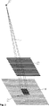
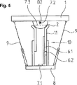
。この旋回運動は角度測定装置7を使って測定される。角度測定装置は、光源7.1と、検出器7.2と、格子7.3とから成る。光源7.1はリンク機構4の支点D4内で部材5に不動に設けられており、かつ支持体3に沿って発散する光線束Lを送る(図2)。光線束Lの範囲内で、検出器7.2は基体1においてリンク機構2の支点D2内にある。ある一定の間隔をおいて、格子7.3は検出器7.2の前方で同様に基体1に固定された状態にあり、したがって格子7.3は検出器7.2に不動に所属している。発散する光線束Lを使用して格子7.3を照射することにより、強度パターンMが形成され、検出器7.2に対する強度パターンの位置は、支持体3の旋回運動に関する尺度であり、それとともに部材5の横の変位の尺度でもある。
基体1あるいは測定されるべき部材5に直接光源7.1と検出器7.2を配設することにより、リンク機構2と4の故障、ならびに支持体3の変位エラーは、角度計測に影響を及ぼさない。角度計測のための光路は、可動な部材5と基体1との間にある。この場合、一方の支点D2,D4内には光源7.1が、もう一方の支点D4,D2内には検出器7.2の感光性の部材の重心が設けられている。図示していない方法で、一方の支点D2,D4内には光源7.1ならびに検出器7.2が設けられており、もう一方の支点D4,D2内には再帰性反射部材が設けられている。この場合、光線の分割は長所であり、したがって光線束は格子7.3を介して一方向へのみ進む。そのとき検出器7.2あるいは光源7.1は、支点D2あるいはD4の部分光線束により反射されたかあるいは結像された位置にある。格子7.3は光源7.1あるいは検出器7.2のどちらかに空間的に固定されている。
1‘ 基礎部分
2 リンク機構
3 支持体
4 リンク機構
5 可動な部材
5‘ 機械部分
6 長さ測定装置
6.1 スケール
6.2 スキャナユニット
7 角度測定装置
7.1 光源
7.2 検出器
7.3 格子
8 可動な部材
11 支持体
60 干渉計
64 光源
M 強度パターン
L 光路
D2 支点
D4 支点
Claims (8)
- 可動な部材(5,8)を基体(1)に接続する、長さが可変の支持体(3,11)と、
それにより支持体(3,11)が、支点(D2)を中心にして基体(1)内で旋回可能に支承されているリンク機構(2)と
支持体(3,11)に沿って、基体(1)に対する可動な部材(5,8)の間隔を測定するための長さ測定装置(6)と、
少なくとも一つの光源(7.1)と、一つの検出器(7.2)と、光源(7.1)あるいは検出器(7.2)に空間的に固定されている、光源(7.1)と検出器(7.2)との間の光路内における一つの格子(7.3)とを有する、可動な部材(5,8)と基体(1)との間の角度を測定するための角度測定装置(7)とを備えた、基体(1)に対する可動な部材(5)の空間的位置を捕捉する位置測定装置において、
光源(7.1)を使用して格子(7.3)を照射することにより、強度パターンMが得られ、検出器(7.2)に対するこの強度パターンの位置が、角度に関する尺度であることによって、角度を測定するための光路(L)が、可動な部材(5,8)と基体(1)との間の支持体(3,11)に沿って延びていること、
支点(D2)において、光源(7.1)、あるいは検出器(7.2)の感光性部材の重心が設けられていること、そしてさらに、
支持体(3)がテレスコープ式に形成され、かつ角度測定装置(7)の光路用のカバーを形成していることを特徴とする位置測定装置。 - 支持体(3)と可動な部材(5)との間に、他のリンク機構(4)が設けられており、このリンク機構により可動な部材(5)が、支点(D4)を中心にして支持体(3)に旋回可能に支承されていることを特徴とする請求項1に記載の位置測定装置。
- 一方の支点(D2,D4)内には光源(7.1)と検出器(7.2)が設けられ、もう一方の支点(D4,D2)内には再帰性反射部材が設けられていることを特徴とする請求項2記載の位置測定装置。
- 一方のテレスコープ部(3.1)にスケール(6.1)が、もう一方のテレスコープ部(3.2)に長さ測定装置(6)のスケール(6.1)を走査するスキャナユニット(6.2)が固定されていることを特徴とする請求項1〜3のいずれか一つに記載の位置測定装置。
- 長さ測定装置が干渉計(60)であることを特徴とする請求項1〜3のいずれか一つに記載の位置測定装置。
- 共通の光源(64)の光が、角度を測定しかつ長さを測定するために、二つの部分光線束(L1,L2)に分割されるように構成されていることを特徴とする請求項5に記載の位置測定装置。
- 格子(7.3)が二次元の強度パターンMを形成する二次元の交差格子であり、検出器(7.2)に対してこの強度パターンの位置が角度に関する尺度であることを特徴とする請求項1〜6のいずれか一つに記載の位置測定装置。
- 可動な部材(5)がプログラム制御された機械部分(5’)で固定されていて、かつ基体(1)が機械の基礎部分(1’)で固定されていることにより、この位置測定装置が、プログラム制御された機械部分(5’)の位置精度を検査するために使用されるように構成されていることを特徴とする請求項1〜7のいずれか一つに記載の位置測定装置。
Applications Claiming Priority (2)
| Application Number | Priority Date | Filing Date | Title |
|---|---|---|---|
| DE10151563A DE10151563A1 (de) | 2001-10-23 | 2001-10-23 | Positionsmessgerät |
| PCT/EP2002/011544 WO2003036226A1 (de) | 2001-10-23 | 2002-10-16 | Positionsmessgerät |
Publications (3)
| Publication Number | Publication Date |
|---|---|
| JP2005506543A JP2005506543A (ja) | 2005-03-03 |
| JP2005506543A5 JP2005506543A5 (ja) | 2008-02-21 |
| JP4377229B2 true JP4377229B2 (ja) | 2009-12-02 |
Family
ID=7702992
Family Applications (1)
| Application Number | Title | Priority Date | Filing Date |
|---|---|---|---|
| JP2003538681A Expired - Fee Related JP4377229B2 (ja) | 2001-10-23 | 2002-10-16 | 位置測定装置 |
Country Status (5)
| Country | Link |
|---|---|
| US (1) | US7274464B2 (ja) |
| EP (1) | EP1442269B1 (ja) |
| JP (1) | JP4377229B2 (ja) |
| DE (1) | DE10151563A1 (ja) |
| WO (1) | WO2003036226A1 (ja) |
Cited By (2)
| Publication number | Priority date | Publication date | Assignee | Title |
|---|---|---|---|---|
| KR101860927B1 (ko) * | 2017-11-09 | 2018-05-24 | 주식회사 흥찬엔지니어링 | 교량 재하 시험 장치 |
| KR101864849B1 (ko) * | 2017-11-09 | 2018-06-05 | 주식회사 신우기술 | 교량 재하 시험 장치 |
Families Citing this family (16)
| Publication number | Priority date | Publication date | Assignee | Title |
|---|---|---|---|---|
| DE102004056726B4 (de) * | 2004-11-19 | 2014-12-24 | Dr. Johannes Heidenhain Gmbh | Verfahren und Vorrichtung zur Bestimmung der räumlichen Lage eines ersten Objektes bezüglich eines zweiten Objektes |
| GB0612914D0 (en) * | 2006-06-16 | 2006-08-09 | Renishaw Plc | Metrology apparatus |
| US20090194664A1 (en) * | 2006-06-16 | 2009-08-06 | Renishaw Plc | Extendable Leg Assembly for Position Measurement Apparatus |
| FR2911956B1 (fr) * | 2007-01-29 | 2009-05-08 | Hispano Suiza Sa | Dispositif de mesure de la position d'un piston dans un cylindre, ensemble d'un cylindre, d'un piston et d'un tel dispositif et moteur d'aeronef comprenant un tel ensemble |
| US20090056440A1 (en) * | 2007-07-10 | 2009-03-05 | Lynn Vendl | Adjustable measuring cup |
| DE102008005384A1 (de) * | 2008-01-22 | 2009-07-23 | Dr. Johannes Heidenhain Gmbh | Längenmesseinrichtung |
| EP2318810B1 (en) * | 2008-08-26 | 2018-08-01 | The University Court Of The University Of Glasgow | Uses of electromagnetic interference patterns |
| DE102010019656B4 (de) * | 2010-05-03 | 2016-09-01 | Etalon Ag | Messgerät |
| EP2875326A4 (en) * | 2012-07-20 | 2016-03-30 | Advanced Test And Automation Inc | SYSTEM AND METHOD FOR TORQUE MEASUREMENT |
| US10105837B2 (en) * | 2013-01-25 | 2018-10-23 | The Boeing Company | Tracking enabled extended reach tool system and method |
| JP6284771B2 (ja) * | 2013-01-29 | 2018-02-28 | 株式会社ミツトヨ | パラレル機構 |
| CN107250712B (zh) * | 2015-02-13 | 2019-09-10 | 日本维克托利克株式会社 | 伸缩柔性管接头的工作状态探测装置和工作状态探测方法 |
| DE102015009393B4 (de) | 2015-07-15 | 2019-07-04 | Gerhard Pfeifer | Wegaufnehmeranordnung sowie Crashtest-Dummy |
| TWI585363B (zh) * | 2015-12-01 | 2017-06-01 | 國立清華大學 | 應用於量測之雙球桿系統及其誤差補償方法 |
| DE102019116280B3 (de) * | 2019-06-14 | 2020-12-17 | Etalon Ag | Verfahren und Vorrichtung zum Bestimmen einer Länge |
| CN110487158B (zh) * | 2019-09-02 | 2021-06-29 | 太原科技大学 | 一种联轴器对中检测装置 |
Family Cites Families (21)
| Publication number | Priority date | Publication date | Assignee | Title |
|---|---|---|---|---|
| DE2240968A1 (de) * | 1972-08-21 | 1974-03-07 | Leitz Ernst Gmbh | Optisches verfahren zur messung der relativen verschiebung eines beugungsgitters sowie einrichtungen zu seiner durchfuehrung |
| DE2549218A1 (de) * | 1974-11-05 | 1976-05-06 | Secretary Industry Brit | Optisches geraet zum bestimmen von achsen |
| US4373804A (en) * | 1979-04-30 | 1983-02-15 | Diffracto Ltd. | Method and apparatus for electro-optically determining the dimension, location and attitude of objects |
| DE3504464C1 (de) | 1985-02-09 | 1986-04-17 | Fraunhofer-Gesellschaft zur Förderung der angewandten Forschung e.V., 8000 München | Transportables Meßgerät zur Überprüfung der Positioniergenauigkeit eines programmgesteuerten Gerätearmes |
| NO164946C (no) * | 1988-04-12 | 1990-11-28 | Metronor As | Opto-elektronisk system for punktvis oppmaaling av en flates geometri. |
| JP2862417B2 (ja) * | 1990-11-16 | 1999-03-03 | キヤノン株式会社 | 変位測定装置及び方法 |
| US5198663A (en) * | 1991-04-03 | 1993-03-30 | Mitutoyo Corporation | Angular velocity sensor with displacement scale and sensor means |
| GB9315843D0 (en) * | 1993-07-30 | 1993-09-15 | Litton Uk Ltd | Improved machine tool |
| US5616917A (en) * | 1995-05-16 | 1997-04-01 | Brown & Sharpe Manufacturing Company | Device for measuring an angle between pivotally-connected members |
| US5741113A (en) * | 1995-07-10 | 1998-04-21 | Kensington Laboratories, Inc. | Continuously rotatable multiple link robot arm mechanism |
| US5765444A (en) * | 1995-07-10 | 1998-06-16 | Kensington Laboratories, Inc. | Dual end effector, multiple link robot arm system with corner reacharound and extended reach capabilities |
| US6098484A (en) * | 1995-07-10 | 2000-08-08 | Kensington Laboratories, Inc. | High torque, low hysteresis, multiple link robot arm mechanism |
| DE19534535C2 (de) | 1995-09-18 | 2000-05-31 | Leitz Mestechnik Gmbh | Koordinatenmeßmaschine |
| DE19621195C1 (de) * | 1996-05-25 | 1997-08-21 | Leica Ag | Verfahren und Vorrichtung zur Richtungsbestimmung zu einem Objekt |
| DE19703735C2 (de) | 1997-01-31 | 2002-02-07 | Leitz Brown & Sharpe Mestechni | Längenveränderliches Element |
| US5944476A (en) * | 1997-03-26 | 1999-08-31 | Kensington Laboratories, Inc. | Unitary specimen prealigner and continuously rotatable multiple link robot arm mechanism |
| US6126381A (en) * | 1997-04-01 | 2000-10-03 | Kensington Laboratories, Inc. | Unitary specimen prealigner and continuously rotatable four link robot arm mechanism |
| US6155768A (en) * | 1998-01-30 | 2000-12-05 | Kensington Laboratories, Inc. | Multiple link robot arm system implemented with offset end effectors to provide extended reach and enhanced throughput |
| US20060249491A1 (en) * | 1999-09-01 | 2006-11-09 | Hell Gravure Systems Gmbh | Laser radiation source |
| DE19956912A1 (de) | 1999-11-26 | 2001-08-09 | Heidenhain Gmbh Dr Johannes | Winkelmeßsystem und Winkelmeßverfahren zur berührungslosen Winkelmessung |
| JP4531965B2 (ja) * | 2000-12-04 | 2010-08-25 | 株式会社トプコン | 振れ検出装置、振れ検出装置付き回転レーザ装置及び振れ検出補正装置付き位置測定設定システム |
-
2001
- 2001-10-23 DE DE10151563A patent/DE10151563A1/de not_active Withdrawn
-
2002
- 2002-10-16 JP JP2003538681A patent/JP4377229B2/ja not_active Expired - Fee Related
- 2002-10-16 EP EP02782919.1A patent/EP1442269B1/de not_active Expired - Lifetime
- 2002-10-16 US US10/493,153 patent/US7274464B2/en not_active Expired - Lifetime
- 2002-10-16 WO PCT/EP2002/011544 patent/WO2003036226A1/de active Application Filing
Cited By (2)
| Publication number | Priority date | Publication date | Assignee | Title |
|---|---|---|---|---|
| KR101860927B1 (ko) * | 2017-11-09 | 2018-05-24 | 주식회사 흥찬엔지니어링 | 교량 재하 시험 장치 |
| KR101864849B1 (ko) * | 2017-11-09 | 2018-06-05 | 주식회사 신우기술 | 교량 재하 시험 장치 |
Also Published As
| Publication number | Publication date |
|---|---|
| US20050018205A1 (en) | 2005-01-27 |
| JP2005506543A (ja) | 2005-03-03 |
| DE10151563A1 (de) | 2003-04-30 |
| WO2003036226A1 (de) | 2003-05-01 |
| EP1442269B1 (de) | 2013-04-17 |
| US7274464B2 (en) | 2007-09-25 |
| EP1442269A1 (de) | 2004-08-04 |
Similar Documents
| Publication | Publication Date | Title |
|---|---|---|
| JP4377229B2 (ja) | 位置測定装置 | |
| JP5324214B2 (ja) | 光学センサ付きの表面検出装置 | |
| EP3182054B1 (en) | Optical configuration for measurement device | |
| KR101864770B1 (ko) | 위치 측정 장치 및 이러한 위치 측정 장치를 포함하는 시스템 | |
| CN107020544B (zh) | 机床 | |
| JP4246071B2 (ja) | 座標測定機械における案内誤差を求めかつ補正する方法 | |
| US20180202796A1 (en) | Measuring device and method for measuring at least one length measurand | |
| JP6309008B2 (ja) | 表面を非常に正確に測定するための方法およびデバイス | |
| JP2008547026A (ja) | 有関節座標計測機再配置装置及び方法 | |
| KR20110133477A (ko) | 로봇 아암을 위한 위치 정보의 측정 | |
| JP2005506543A5 (ja) | ||
| JP6288280B2 (ja) | 表面形状測定装置 | |
| EP1085294B1 (en) | System for inspecting and/or processing a sample | |
| JP2907545B2 (ja) | 光学要素または系を検査する方法および装置 | |
| JP5606039B2 (ja) | ステージ装置及び波面収差測定装置 | |
| JP2004333369A (ja) | 3次元形状測定装置および3次元形状測定方法 | |
| JP5641514B2 (ja) | 非接触変位計測装置 | |
| JP7475163B2 (ja) | 測定装置 | |
| JPH05164525A (ja) | レーザ式座標測定装置の測定ヘッド | |
| JP2010223775A (ja) | 干渉計 | |
| JP2006010645A (ja) | 検出装置及びステージ装置 | |
| JP2013253915A (ja) | レンズ面間隔測定装置 | |
| JP2014002026A (ja) | レンズ形状測定装置およびレンズ形状測定方法 | |
| JPH0743156A (ja) | 測量装置 | |
| Vann | Six degree of freedom sensor |
Legal Events
| Date | Code | Title | Description |
|---|---|---|---|
| A521 | Written amendment |
Free format text: JAPANESE INTERMEDIATE CODE: A523 Effective date: 20051013 |
|
| A621 | Written request for application examination |
Free format text: JAPANESE INTERMEDIATE CODE: A621 Effective date: 20051013 |
|
| A977 | Report on retrieval |
Free format text: JAPANESE INTERMEDIATE CODE: A971007 Effective date: 20070726 |
|
| A131 | Notification of reasons for refusal |
Free format text: JAPANESE INTERMEDIATE CODE: A131 Effective date: 20070904 |
|
| A524 | Written submission of copy of amendment under section 19 (pct) |
Free format text: JAPANESE INTERMEDIATE CODE: A524 Effective date: 20071203 |
|
| A02 | Decision of refusal |
Free format text: JAPANESE INTERMEDIATE CODE: A02 Effective date: 20080617 |
|
| A521 | Written amendment |
Free format text: JAPANESE INTERMEDIATE CODE: A523 Effective date: 20081015 |
|
| A911 | Transfer of reconsideration by examiner before appeal (zenchi) |
Free format text: JAPANESE INTERMEDIATE CODE: A911 Effective date: 20081224 |
|
| RD03 | Notification of appointment of power of attorney |
Free format text: JAPANESE INTERMEDIATE CODE: A7423 Effective date: 20090218 |
|
| A131 | Notification of reasons for refusal |
Free format text: JAPANESE INTERMEDIATE CODE: A131 Effective date: 20090331 |
|
| A521 | Written amendment |
Free format text: JAPANESE INTERMEDIATE CODE: A523 Effective date: 20090415 |
|
| TRDD | Decision of grant or rejection written | ||
| A01 | Written decision to grant a patent or to grant a registration (utility model) |
Free format text: JAPANESE INTERMEDIATE CODE: A01 Effective date: 20090811 |
|
| A01 | Written decision to grant a patent or to grant a registration (utility model) |
Free format text: JAPANESE INTERMEDIATE CODE: A01 |
|
| A61 | First payment of annual fees (during grant procedure) |
Free format text: JAPANESE INTERMEDIATE CODE: A61 Effective date: 20090910 |
|
| R150 | Certificate of patent or registration of utility model |
Ref document number: 4377229 Country of ref document: JP Free format text: JAPANESE INTERMEDIATE CODE: R150 Free format text: JAPANESE INTERMEDIATE CODE: R150 |
|
| FPAY | Renewal fee payment (event date is renewal date of database) |
Free format text: PAYMENT UNTIL: 20120918 Year of fee payment: 3 |
|
| FPAY | Renewal fee payment (event date is renewal date of database) |
Free format text: PAYMENT UNTIL: 20130918 Year of fee payment: 4 |
|
| R250 | Receipt of annual fees |
Free format text: JAPANESE INTERMEDIATE CODE: R250 |
|
| R250 | Receipt of annual fees |
Free format text: JAPANESE INTERMEDIATE CODE: R250 |
|
| R250 | Receipt of annual fees |
Free format text: JAPANESE INTERMEDIATE CODE: R250 |
|
| R250 | Receipt of annual fees |
Free format text: JAPANESE INTERMEDIATE CODE: R250 |
|
| R250 | Receipt of annual fees |
Free format text: JAPANESE INTERMEDIATE CODE: R250 |
|
| R250 | Receipt of annual fees |
Free format text: JAPANESE INTERMEDIATE CODE: R250 |
|
| R250 | Receipt of annual fees |
Free format text: JAPANESE INTERMEDIATE CODE: R250 |
|
| LAPS | Cancellation because of no payment of annual fees |