JP4367828B2 - Drilling machine - Google Patents
Drilling machine Download PDFInfo
- Publication number
- JP4367828B2 JP4367828B2 JP2002367191A JP2002367191A JP4367828B2 JP 4367828 B2 JP4367828 B2 JP 4367828B2 JP 2002367191 A JP2002367191 A JP 2002367191A JP 2002367191 A JP2002367191 A JP 2002367191A JP 4367828 B2 JP4367828 B2 JP 4367828B2
- Authority
- JP
- Japan
- Prior art keywords
- processing
- machining
- printed circuit
- circuit board
- workpiece
- Prior art date
- Legal status (The legal status is an assumption and is not a legal conclusion. Google has not performed a legal analysis and makes no representation as to the accuracy of the status listed.)
- Expired - Lifetime
Links
Images


Landscapes
- Laser Beam Processing (AREA)
Description
【0001】
【発明の属する技術分野】
本発明は、プリント電子回路基板、電子部品パッケージ等の素材に所要の加工を施す穴明け加工装置に関し、特に、ロール状に巻回された長尺フィルム状の被加工素材に穴明け加工した後に巻き取る構成を備えたレーザ式、ドリル式等の加工装置に用いて好適な穴明け加工装置に関する。
【0002】
【従来の技術】
ロール状に巻かれたフィルム状(テープ状)の素材、例えばフレキシブルプリント基板を巻き出して穴明け加工を施した後、再度ロール状に巻き取るように構成したプリント基板加工機(レーザ加工機)が知られている(例えば、特許文献1参照)。上記穴明け加工の手段としては、機械式のドリルを用いるもの、或いはレーザ光を用いるものなどがある。
【0003】
上記プリント基板加工機は、図4に示すように、図の左右方向(以下X方向と呼ぶ)に移動可能なテーブル1と、前後方向(以下Y方向と呼ぶ)に移動可能なテーブル2とで構成されるXYテーブル上に、加工対象となる被加工素材3を保持した状態で、レーザ発振器(図示せず)から発振されたレーザ光6を、ガルバノミラー4、5、fθレンズ7等を有する加工ヘッド8に導き、ガルバノミラー4、5により反射制御し、更にfθレンズ7を通して、前記被加工素材3上に照射することで穴明け加工する。
【0004】
このようなレーザ加工機では、穴の加工位置精度を確保する目的で、fθレンズ7の球面収差の影響が少ない部分を主体に使用することが通常である。このため、テーブルが停止している状態で一度に加工できる範囲は、A×A(Aは数10mm)に限定される。この範囲を、加工ヘッド8のスキャン領域80と呼ぶ。したがって、加工すべき範囲がスキャン領域80の大きさA×Aより大きい場合には、XYテーブルによりプリント基板等の被加工素材3を移動させながら全体の加工を行なうことが必要となる。
【0005】
このため、被加工素材3が、XYテーブル上に載置される大きさであれば、高精度の加工を行なうことが容易に可能であるが、ロール状に巻かれた長尺のフレキシブルプリント基板等を加工する場合には、例えば図5に示すような形態を取ることが必要となる。なお、図5においては、各部分の記号が多いため2つの図を併記して示している。従って、図5(a)には光路系を含む機構の概略を、また図5(b)にはフレキシブルプリント基板10の搬送路を構成するローラ等の要素を中心に示している。
【0006】
同図のレーザ加工機では、ロール状に巻回されたフレキシブルプリント基板(以下単にプリント基板とも呼ぶ)10を被加工素材として使用する。このレーザ加工機は加工装置200を有しており、加工装置200は、レーザ発振器9等を有する加工源部11の下方にベッド12を備えている。このベッド12上には、Xテーブル13が、ベッド12に対する図の左右方向に直線案内手段14を介して移動可能に支持されている。Yテーブル15は、Xテーブル13に対する図の前後方向に直線案内手段16を介して移動可能に支持されている。Xテーブル13とYテーブル15とにより、水平面内の2方向に自由度(即ち2自由度)を有するXYテーブルが構成されている。
【0007】
図6は、前記XYテーブル上に設置された昇降テーブル(以下Zテーブルとも呼ぶ)18の詳細を示したものであり、箱状に形成された枠17は、Yテーブル15上に固定されている。Zテーブル18は、枠17に対して上下方向(以下Z方向と呼ぶ)に移動可能に支持されている。エアシリンダ19は、Yテーブル15とZテーブル18との間に配置されて、Zテーブル18を上下方向に昇降移動させる。前記XYテーブル13,15とZテーブル18とによって加工テーブル100(図5参照)が構成されている。
【0008】
前記枠17には支持部材20が固定されており、支持部材20には軸21が回転可能に支持されている。軸21には、クランパレバー22が所定の間隔で固定されており、クランパレバー22にはクランププレート23が固定されている。軸21の一端には、レバー24が固定されている。枠17にはエアシリンダ25の一端が揺動可能に支持され、エアシリンダ25の他端がレバー24に揺動可能に結合されている。これら軸21、エアシリンダ25、クランパレバー22及びクランププレート23等によって、Zテーブル18上のフレキシブルプリント基板10の幅方向における両側端部を拘束、解放するクランプ機構が構成されている。
【0009】
また、図5(a)、(b)に示すように、Yテーブル15上には、前記Zテーブル18をX方向において挟むように支持部材26a、26bが立設固定されている。コラム28には、ガイドローラ44a、44bが回転可能に支持されている。支持部材26a、26bには、駆動ローラ27a、27b、並びにピンチローラ38a、38bが回転可能に支持されている。駆動ローラ27a、27bは、駆動手段(図示せず)により正逆方向に回転駆動されると共に、それぞれピンチローラ38a、38bと間のニップ部にフレキシブルプリント基板10を挟み込み、これを拘束する。駆動ローラ27a、27bの上端面は、Zテーブル18が上昇端に位置するときの上面と略々同じ高さになるように設定されている。
【0010】
ベッド12上にはコラム28が固定されており、このコラム28上にはレーザ発振器9が固定されている。コラム28の所定位置には、ガルバノミラー4、5、及びfθレンズ7が支持されている。レーザ発振器9から発振されたレーザ光6は、ガルバノミラー4、5及びfθレンズ7を介して、昇降テーブル18上に固定されたフレキシブルプリント基板10に垂直に照射される。
【0011】
巻き出し装置30A及び巻き取り装置30Bは、前記ベッド12、加工テーブル100、コラム28、及びレーザ発振器9を有する加工装置200の両側面にそれぞれ配置されている。巻き出し装置30Aと巻き取り装置30Bとは互いに同じ構成を有するので、ここでは巻き出し装置30Aを中心に説明する。なお、巻き出し装置30Aと巻き取り装置30Bとは、各符号の末尾にそれぞれa、bを付けることでその構成を区別する。
【0012】
巻き出し装置30Aにおいて、フレーム31aには、ガイドローラ32a、33a、34aが、フレキシブルプリント基板10の搬送方向に沿ってそれぞれ回転可能に支持されている。フレーム31aには、ガイドローラ32aと34aとの間に、駆動手段(図示せず)により正逆方向に回転駆動される駆動ローラ35aが支持されている。フレーム31aには更に、駆動ローラ35aに対向してピンチローラ36aが回転可能に支持されており、このピンチローラ36aは、駆動ローラ35aとの間のニップ部にフレキシブルプリント基板10を挟み込み、拘束する。
【0013】
なお、ロール状に巻かれたフレキシブルプリント基板10は、フレーム31aに回転可能に支持された駆動軸(図示せず)に固定支持されて、駆動手段(図示せず)により正逆方向に回転駆動される。
【0014】
ここで、巻き出し装置30A側のフレキシブルプリント基板10のロール状部分を原反ロール部10a、また巻き取り装置30B側の前記基板10のロール状部分を加工反ロール部10bと呼ぶこととする。また、フレキシブルプリント基板10は、加工の進行に伴って原反ロール部10a側から巻き出され、加工反ロール部10b側に巻き取られて行く。この際、加工テーブル100においては、フレキシブルプリント基板10は、Xテーブル13の動作方向であるX方向、即ち該プリント基板10の長手方向に搬送されて行く。また、この時、Y方向はフレキシブルプリント基板10の幅方向と一致する。
【0015】
このような構成において、巻き出し装置30A側の原反ロール部10aから引き出されたフレキシブルプリント基板10は、ガイドローラ32a、33a、駆動ローラ35a及びピンチローラ36a間のニップ部、並びにガイドローラ34aを経由して加工装置200に導かれる。そして、プリント基板10は、加工装置200におけるガイドローラ44a、駆動ローラ27a及びピンチローラ38a間のニップ部、昇降テーブル18、駆動ローラ27b及びピンチローラ38b間のニップ部、並びにガイドローラ44bを経由して巻き取り装置30Bに導かれる。プリント基板10は更に、ガイドローラ34b、駆動ローラ35b及びピンチローラ36b間のニップ部、ガイドローラ33b、並びにガイドローラ32bを経由して、加工反ロール部10bでロール状に巻き取られる。
【0016】
上記搬送経路においてフレキシブルプリント基板10は、昇降テーブル18上で、加工領域の基板幅方向における両側端部が、図6に示したエアシリンダ25の作動で揺動作動するクランププレート23によって昇降テーブル18上に押しつけられて固定(拘束)され、この状態でレーザ発振器9から発振されるレーザ光6を照射されて所要の加工を施される。なお、この時、フレキシブルプリント基板10は昇降テーブル18に対して相対的な変位を生じないため、駆動ローラ27a、27bは動作しない。この際、ガイドローラ34aとガイドローラ44aとの間、及びガイドローラ44bとガイドローラ34bとの間には、自由ループ40a、40bが形成されている。
【0017】
この「自由ループ」は、図7に示すように、2つのガイドローラ44、34間に形成されるフレキシブルプリント基板10の垂れ下がった部分を意味するものである。そして、ガイドローラ44、34間の距離を自由ループのスパンL、またガイドローラ44、34の各上端面から基板10の垂れ下がった最下部までの垂直距離を自由ループの高さ(或いは深さ)H、更にガイドローラ44、34位置における基板10の幅方向ずれ量をずれ幅Qと呼ぶこととする。図5に示すように、自由ループ40a、40bは、加工時において、Yテーブル15の図の前後方向(紙面の手前・奥方向)の移動に対して、加工装置200の両側に配置されている巻き出し装置30A、巻き取り装置30B側に配置されたプリント基板10の位置とのずれを吸収する役割を果たす。
【0018】
次に、上記自由ループの作用について説明する。例えば、加工時にYテーブル15が図5の前後方向に移動すると、自由ループ40a、40bの形状を維持しているガイドローラ44、34の間で、フレキシブルプリント基板10がねじれることになる。このねじれによって、昇降テーブル18上に固定された部分のプリント基板10のY方向への移動が可能となる。
【0019】
したがって、加工時におけるYテーブル15の移動動作に伴う、昇降テーブル18上にてプリント基板10の固定された部分と、ロール部10a、10bとの相対的な位置の移動、ずれを、自由ループ40a、40bによって吸収し得る。
【0020】
そして、加工が終了すると、Xテーブル13とYテーブル15とは、それぞれ次の加工に備えて、加工開始時のテーブル位置(以下、加工開始位置、加工初期位置とも呼ぶ)に復帰する。次いで、クランププレート23を開放すると共に昇降テーブル18を下降させてフレキシブルプリント基板10を離間した後、駆動ローラ27a、27bを回転させて、フレキシブルプリント基板10の既加工部分を、巻き取り装置30B側の加工反ロール部10bに向けて搬出すると同時に、新たに加工すべき未加工部分を、巻き出し装置30A側の原反ロール部10aから引き出して搬入する。
【0021】
この時、自由ループ40aの高さHは、巻き出し装置30Aと加工装置200本体との間に設置された光電センサ等の検知手段(図示せず)の検知結果に基づき、図示しない制御部にて検出される。同様に、自由ループ40bの高さHは、加工装置200本体と巻き取り装置30Bとの間に設置された光電センサ等の検知手段(図示せず)の検知結果に基づき、図示しない制御部にて検出される。
【0022】
そして、フレキシブルプリント基板10の既加工部分を巻き取り装置30B側に向けて搬出すると、自由ループ40bの高さ寸法が大きくなる。この高さ寸法が所定の高さHlまで下がった(大きくなった)ことが検出されると、駆動ローラ35bが回転して、プリント基板10をX方向における図の右方向に移動させ、自由ループ40bの高さHlを小さくする。逆に、自由ループ40bの高さ寸法がHhまで上がった(小さくなった)ことが検出されると、駆動ローラ35bは回転を停止する。また、加工反ロール部10bは、フレキシブルプリント基板10に与える張力が所要の値の範囲となるように、図示しない駆動手段により回転駆動される。
【0023】
フレキシブルプリント基板10の末加工部分を巻き出し装置30A側から搬入すると、自由ループ40aの高さは小さくなる。この高さが所定の高さHhまで上がった(小さくなった)ことが検出されると、駆動ローラ35aが回転してプリント基板10を加工装置200側(図の右方向)に巻き出し、自由ループ40aの高さ寸法を大きくする。逆に、自由ループ40aの高さ寸法がHlまで下がった(大きくなった)ことが検出されると、駆動ローラ35aは回転を停止する。また、原反ロール部10aは、プリント基板10に与える張力が所定の値の範囲となるように、図示しない駆動手段により回転駆動される。
【0024】
ここで、フレキシブルプリント基板の加工と搬送のシーケンスを見ると、図8に示すようになる。いま、加工テーブル100上に固定されたフレキシブルプリント基板部分、即ちロール状の原反、加工反の巻き出し、巻き取りを行なわずに一度に加工できる部分を、加工ブロック(以下、加工領域とも呼ぶ)と呼ぶこととする。
【0025】
まず、加工テーブル100上にフレキシブルプリント基板10を搬送する際には、1つの加工ブロックの加工初期位置に加工テーブル100を移動させる(ステップ1100)。ここで、例えばプリント基板10の原反に巻かれている順に行なうものとすれば、加工の初期位置は、加工ブロックのうちの先頭部分(加工反側に最も近い部分)が加工ヘッド直下にある状態であり、この時、加工テーブル100は最も原反側、即ち巻き出し装置30A側に近い位置(言い換えれば、X座標値が最も小さい位置)に位置決めされた状態となる。この後、加工テーブル100側に支持された駆動ローラ27によってプリント基板10を搬送し(ステップ1200)、加工テーブル100上に新たな加工ブロックが位置した時点で、クランプ機構によってこの加工ブロックをクランプして固定し(ステップ1300)、加工テーブル100をX方向、Y方向の適時移動させることにより、この新たな加工ブロックに対する穴明け加工を実施する(ステップ1400)。
【0026】
加工にあたっては、一般に、加工効率の観点から、加工ブロックの端から加工ヘッド8のスキャン領域分ずつ順次加工を進めて行くことになるため、例えば、加工開始時点においては加工ブロック中の最も加工側に近い部分の加工直前の状態となっている。つまり、この時、加工テーブル100は最も原反側、即ち巻き出し装置30A側に近い位置(言い換えれば、X座標値が最も小さい位置)に置かれた状態である。
【0027】
一方、加工終了時点においては、加工ブロック中の最も原反側に近い部分の加工直後の状態となっている。すなわち、加工ブロック中の最も原反に近い部分が、加工ヘッド8直下の位置となる状態であり、この時、加工テーブル100は最も加工反側、即ち巻き取り装置30B側に近い位置(言い換えれば、X座標値が最も大きい位置)に位置した状態となる。そして、加工テーブル100に固定された一つの加工ブロックの加工終了後、図示しない制御部が、他の全ての加工ブロックに対する加工が終了しているか否かを判定し(ステップ1500)、未終了であれば、一連の加工の初期位置に加工テーブル100を再度移動させて(ステップ1100)、ステップ1100〜1500の処理を繰り返す。
【0028】
【特許文献1】
特開2000−246479号公報
【0029】
【発明が解決しようとする課題】
以上に示されるように、加工ブロックに対する加工の開始位置と終了位置とは、一般に加工テーブルの動作範囲の両端に位置することになる。したがって、加工終了位置から加工開始の初期位置への加工テーブル100の移動、並びに、フレキシブルプリント基板10の一加工ブロック分の搬送に要する時間は、加工に寄与しない時間であり、この時間の分だけ加工システムとしての効率が低下することになる。
【0030】
また、以上の説明においては、被加工素材であるフレキシブルプリント基板の枚数については何ら言及しなかったが、加工が貫通穴である場合においては、複数枚のプリント基板を重ねて同時に加工することにより加工効率を向上させることが可能である。このような場合、上記の例で示したような駆動ローラ27及びピンチローラ38によりプリント基板10を挟んで搬送する方式では、個々の基板間のずれ等が発生し易く、安定した基板搬送の実施が困難になる虞がある。
【0031】
本発明の目的は、上記の事情に鑑み、被加工素材を複数枚重ねて同時に加工するような場合にあっても素材の搬送を安定に行うことができると共に、被加工素材の搬送に要する時間のような加工に寄与しない時間を可及的に削減して、加工システムとしての効率を向上させることができる穴明け加工装置を提供することにある。
【0032】
【課題を解決するための手段】
上記の目的を達成するため、本発明は、ロール状に巻回された未加工の被加工素材を巻き出す巻き出し装置と、該巻き出し装置からの前記被加工素材に対して穴明け加工を施す加工部を有する加工装置と、該加工装置による加工済の前記被加工素材をロール状に巻き取る巻き取り装置と、を前記被加工素材の搬送方向に沿って順次備える穴明け加工装置において、
前記加工装置の本体に対し相対移動可能に配置されて、前記被加工素材の長手方向に存する複数の加工ブロックを前記加工部による加工位置に順次位置決めするように移動する加工テーブルと、
前記加工テーブルと一体的に配置されて、該加工テーブルが前記加工部による加工の開始位置から終了位置に移動する際に前記被加工素材を前記加工テーブルに対して拘束し、かつ該加工テーブルが前記加工終了位置から前記加工開始位置に復帰する際には前記被加工素材を前記加工テーブルから解放するように動作するクランプ手段と、
前記加工テーブルを前記搬送方向の前後にて挟む位置に、前記被加工素材を挟持して拘束する一対のローラをそれぞれ備え、前記加工テーブルが前記加工終了位置に到達した際、前記クランプ手段が前記被加工素材を解放する動作に先立って、該被加工素材の前記加工装置に対する相対位置を固定し、かつ前記加工テーブルが前記加工開始位置に復帰した際、前記クランプ手段が前記被加工素材を拘束した後に、該被加工素材の前記加工装置に対する相対位置の固定状態を解除するように前記各一対のローラを動作させる相対位置固定手段と、
前記加工テーブル及び前記相対位置固定手段のいずれか一方に備えられ、前記加工テーブルの前記加工開始位置への復帰時に、前記被加工素材の表面に対する垂直方向に変位して前記加工テーブルと該加工テーブル上方の前記被加工素材とを垂直方向に離間させて、前記加工テーブルと前記被加工素材とを相対摺動させないように作動する垂直変位機構と、を備えることを特徴としている。
【0033】
【発明の実施の形態】
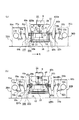
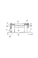
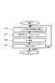
以下、本発明に係る穴明け加工装置を適用したレーザ加工装置の第1の実施形態を図1ないし図3に沿って説明する。図1は、本実施形態におけるレーザ加工装置を示す正面図、図2は、図1における2つの相対位置固定装置を共通に示す側面図、図3は、本実施形態における加工動作のシーケンスを示す図である。
【0034】
なお、図1では、各部分の符号が多いため、図5と同様に、2つの図を併記して示している。つまり、図1(a)には光路系を含む機構の概略を、また図1(b)にはフレキシブルプリント基板10の搬送路を形成するローラ等の要素を中心に示している。図1(a)、(b)において、図5ないし図7に示した構成要素や構成部分と共通する機能を備えるものには同じ符号を付けて示している。
【0035】
まず、図1の加工装置200において、レーザ発振器9等を有する加工源部11の下方にはベッド12が配置され、このベッド12上には直線案内手段16を介してYテーブル(第2テーブル)15が、該ベッド12に対する前後方向(紙面の手前・奥方向)に移動可能に支持されている。また、Yテーブル15上には直線案内手段14を介してXテーブル(第1テーブル)13が、Yテーブル15に対する図の左右方向に移動可能に支持されている。
【0036】
したがって、本レーザ加工装置は、図5に示した従来例に比してXYテーブルの構成は異なるものの、Xテーブル13とYテーブル15とにより水平面内の2方向に自由度(つまり2自由度)を持ったXYテーブルを構成している点は同様である。更に、加工ヘッド8、巻き出し装置30A、巻き取り装置30Bの各構成及び各動作方法等についても、図5の例と同様である。
【0037】
前記XYテーブル上に設置されたZテーブル18に関して、図1に示す本実施形態例では、箱状に形成された枠17(図6参照)がXテーブル13上に固定されている点と、エアシリンダ19(図6参照)がXテーブル13とZテーブル18との間に配置されている点以外は図6の従来例と同様であって、XYテーブル(13、15)とZテーブル18とによって加工テーブル100が構成されている。本実施形態における該加工テーブル100は、加工装置200の本体に対し相対移動可能に配置されて、フレキシブルプリント基板10の長手方向に存する複数の加工ブロック(加工領域)を、加工ヘッド(加工部)8の直下の加工位置に順次位置決めするように移動する。
【0038】
次に、相対位置固定装置(相対位置固定手段)について説明する。すなわち、Yテーブル15上には、巻き出し装置30A側に相対位置固定装置400aが、巻き取り装置30B側に相対位置固定装置400bがそれぞれ支持部材49a、49bを介して設置されている。更に、加工装置200本体のコラム28には、巻き出し装置30A側の側面にガイドローラ44aが、巻き取り装置30B側の側面にガイドローラ44bが、それぞれ回転可能に支持されている。なお、2つの相対位置固定装置400a、400bは互いに同じ構成を有するので、ここではこれらの一方について説明する。相対位置固定装置400aと400bとは、各符号の末尾にそれぞれa、bを付けることでその構成を区別する。
【0039】
すなわち、図1における相対位置固定装置400a又は400bを同図の左方向又は右方向から見た状態で概略的に示す図2に示すように、Yテーブル15上には、互いに対向するように2つの支持部材49、49が立設固定されている。これら支持部材49、49の間にはガイドローラ45が回転可能に支持されており、各支持部材49にはそれぞれ、外側に突出するように軸480が回転可能に支持されている。各軸480、480にはレバー48、48がそれぞれ固定されており、これらレバー48、48には、双方の間に渡るように軸481が固定されている。この軸481の中間部分には、ガイドローラ45に対向する形でピンチローラ46が固定されている。
【0040】
支持部材49、49の一方には、エアシリンダ47の一端が支持されており、このエアシリンダ47の他端はレバー48に揺動可能に結合されている。したがって、エアシリンダ47を伸縮作動させることにより、軸480、480を中心としてレバー48を揺動動作させ、ピンチローラ46をガイドローラ45に対して接離動作させることができる。そして、ピンチローラ46をガイドローラ45に押圧する動作時には、ガイドローラ45とピンチローラ46との間にフレキシブルプリント基板10(図1参照)を挟み込み、拘束することができる。なお、ガイドローラ45、つまり両固定装置400a、400bにおける各ガイドローラ45a、45bの上端面は、Zテーブル18が上昇端にあるときの上面と概ね同じ高さに設定されている。
【0041】
このような構成において、巻き出し装置30A側の原反ロール部10aから引き出されたフレキシブルプリント基板10は、ガイドローラ32a、33a、駆動ローラ35a及びガイドローラ34aを経て加工装置200に導かれる。更に、このフレキシブルプリント基板10は、ガイドローラ44a、45a、Zテーブル18、及びガイドローラ45b、44bを経て巻き取り装置30Bに導かれ、ガイドローラ34b、駆動ローラ35b、及びガイドローラ33b、32bを経て、加工反ロール部10bにてロール状に巻き取られる。
【0042】
そして、Zテーブル18上では、フレキシブルプリント基板10の加工領域(加工ブロック)における素材幅方向(図1の紙面の手前・奥方向)の両側端部が、図6に示したクランプ機構(クランプ手段)におけるエアシリンダ25の作動で揺動するクランププレート23によって、Zテーブル18上に押し付けられて固定(拘束)される。この状態において、レーザ発振器9から発振されるレーザ光6がフレキシブルプリント基板10に照射されて、所要の穴明け加工が行なわれる。また、ガイドローラ34a、44aの間、及びガイドローラ44b、34bの間には、それぞれ自由ループ40a、40bが形成されている。
【0043】
更に、加工の進行に伴い、Zテーブル18は、Xテーブル13及びYテーブル15の動作に伴い、前記クランプ機構によって該Zテーブル18上(つまり加工テーブル100上)に固定したフレキシブルプリント基板10と共にX、Y方向に移動する。この時、上記自由ループ40a、40bによって、このテーブル移動に伴うフレキシブルプリント基板10の変位が吸収される。具体的には、図示しない制御部にて自由ループ40a、40bの各高さを検出して、原反ロール部10aの巻き出しと加工反ロール部10bの巻き取りを行なう訳であり、その手法は従来技術において述べた通りである。
【0044】
そして、フレキシブルプリント基板10を巻き出した個所から順次加工を行なおうとする際、加工開始時にはXテーブル13は、巻き出し装置30A側(図1における左側、即ちX座標の小さい側)に位置している。また、加工が終了した時点では、Xテーブル13は巻き取り装置30B側(図1における右側、即ちX座標の大きい側)に位置している。
【0045】
そして、加工が終了した際、その加工終了位置において、相対位置固定装置400a、400bにおけるエアシリンダ47a、47bの作動で、ピンチローラ46a、46bをガイドローラ45a、45bにそれぞれ押し付け、フレキシブルプリント基板10の搬送方向(X方向)における加工テーブル100の両側(前後)においてこのプリント基板10を挟み込み、そのYテーブル15に対する相対位置を固定する。この時点でYテーブル15がベッド12に対するY方向移動を規制されているので、プリント基板10は即ち、加工装置200に対する相対位置を固定されるのである。
【0046】
引き続き、図6に示したエアシリンダ25の作動でクランププレート23をプリント基板10から離反させて該基板10を解放すると共に、エアシリンダ19の作動でZテーブル18を下降させて、フレキシブルプリント基板10をZテーブル18(つまり加工テーブル100)の上面から離間させる。
【0047】
この後、Xテーブル13とYテーブル15とは、それぞれ次の加工に備えて、加工開始時のテーブル位置、即ち巻き出し装置30A側の加工初期位置に戻る。この場合、相対位置固定装置400a、400bによってフレキシブルプリント基板10の加工装置200に対する相対位置が固定され、かつZテーブル18が下降しているため、フレキシブルプリント基板10と、加工テーブル100におけるZテーブル18上面とは接触しない。
【0048】
つまり、加工テーブル100が、プリント基板10の表面に対する垂直方向(Z方向)に変位(昇降移動)し得るZテーブル(垂直変位機構)18を有し、このZテーブル18の作動により、加工テーブル100の加工開始位置への復帰時に、加工テーブル100と該加工テーブル上方のフレキシブルプリント基板10との相対摺動を回避することができる。これにより、プリント基板10にダメージを与えることなく、X方向に沿ったXテーブル13の加工開始位置への高速移動が可能となる。また、Zテーブル18を昇降動作させる代りに、相対位置固定装置400を支持部材49に対して上下に並進又は揺動移動させるように構成することができ、この場合にも、上記と同様の効果が得られる。
【0049】
次いで、加工開始位置において、Zテーブル18が上昇すると共に、フレキシブルプリント基板10の加工領域における該基板10の幅方向での両側端部が、クランププレート23の作動でZテーブル18上に押し付けられ固定された後、エアシリンダ47の作動でピンチローラ46がガイドローラ45から離反して、プリント基板10の加工装置200に対する相対位置の固定状態が解除され、次の穴明け加工の準備が完了する。
【0050】
以上のように、前記クランプ機構は、加工テーブル100と一体的に配置されて、加工テーブル100が加工ヘッド(加工部)8による加工の開始位置から終了位置に移動する際にプリント基板10を加工テーブル100に対して拘束し、かつ加工テーブル100が加工終了位置から加工開始位置に復帰する際にはプリント基板10を加工テーブル100から解放するように動作している。また、前記相対位置固定装置400a、400bは、加工テーブル100が加工終了位置に到達した際、クランプ機構がフレキシブルプリント基板10を解放する動作に先立って、該プリント基板10の加工装置200に対する相対位置を固定し、かつ加工テーブル100が加工開始位置に復帰した際、クランプ機構がプリント基板10を拘束した後に、このプリント基板10の加工装置200に対する相対位置の固定を解放するように動作している。
【0051】
また、上述の加工の実施中には、従来の穴明け加工の方法及び本発明に係る穴明け加工の方法のいずれにおいても、加工ブロック(加工領域)を加工ヘッド8の直下に順次位置させるために、加工テーブル100(即ちこのテーブル100に含まれるXテーブル13)を移動させるのであるが、この加工テーブル100の移動により、フレキシブルプリント基板10が加工装置200に対して相対的に移動することとなる。言い換えれば、加工テーブル100の移動によって、フレキシブルプリント基板10を加工中に移動搬送していることになる。
【0052】
一方で、1つの加工ブロックの加工終了後には、次の加工ブロックの加工のために、加工テーブル100を加工初期位置(加工開始時のテーブル位置)に戻す動作が必要になる。しかしこの際、従来例で説明したように、フレキシブルプリント基板10が加工テーブル100に対して固定された状態であると、プリント基板10自体も加工装置200本体に対して、加工テーブル100の移動距離と同じ距離だけ上記加工初期位置に向けて移動されることになる。つまりこれは、加工中に搬送されたフレキシブルプリント基板10を逆方向に戻す移動動作を行なっていることに相当する。
【0053】
このことは、フレキシブルプリント基板10の搬送駆動機構を、加工テーブル100内に設置したことに起因する問題であり、言い換えれば、当該搬送駆動機構を、加工テーブル100に対してプリント基板10を相対的に搬送するための機構として機能させているためである。すなわち、加工テーブル100の移動と、フレキシブルプリント基板10の搬送駆動とが別々の機能を果たす機構として具備されているということが問題である。
【0054】
これに対して、本発明に係る実施形態では、一連の加工サイクルにおいて、加工テーブル100がフレキシブルプリント基板10の長手方向、即ち従来例並びに本実施形態で言うX方向(搬送方向)にて往復動するという事実に着目し、加工テーブル100のこの動作自体を活用して被加工素材、つまりフレキシブルプリント基板10の搬送機能を兼備させようとし、それを実現したのである。
【0055】
以上を整理したものが、図3に示すシーケンスである。繰り返すが、加工テーブル100上に固定されたフレキシブルプリント基板10部分、即ち、原反ロール部10a、加工反ロール部10bの巻き出し、巻き取りを行なわずに一度に加工できる部分を、加工ブロックと呼ぶ。
【0056】
まず、一つの加工ブロックにおける加工初期位置に加工テーブル100を位置決めする(ステップ2100)。つまり、図6に示したクランパレバー22やクランププレート23等を有するクランプ機構によって、加工テーブル100上に新たな加工ブロックを固定し(ステップ2200)、この加工ブロックに対する穴明け加工を実施する(ステップ2300)。そして、1ブロック分の加工が終了した時点で、他の全ての加工ブロックに対する加工が終了しているか否かを判定する(ステップ2400)。その結果、未終了と判定した場合には、ガイドローラ45に対してピンチローラ46を押圧することによって、フレキシブルプリント基板10の加工装置200に対する相対位置を固定し、更に、クランプ機構を開放しかつZテーブル18を下降させて、加工テーブル100を加工開始位置に復帰させて位置決めし(ステップ2100)、上記と同様の工程を繰り返し実行する。
【0057】
ここで、図3に示した本実施形態の動作シーケンスと図8に示した従来の動作シーケンスを比較すると、本実施形態例においては、従来例にあるような駆動ローラ27によるフレキシブルプリント基板10の搬送処理(ステップ1200)が不要である。また、従来例において、加工テーブル100が次の加工ブロックに対する加工のために加工初期位置に復帰する動作(ステップ1100、2100)は必要不可欠な動作であるが、本実施形態例では、この復帰動作自体によって加工テーブル100に対するフレキシブルプリント基板10の固定位置を更新することにより、加工に直接的に寄与しない時間が極力削減されている。
【0058】
以上の本実施形態の説明では、特に被加工素材自体の構成に関しては述べなかったが、例えば、複数枚数のフィルム素材が重ね合わされている被加工素材を使用する場合においても本実施形態を全く同様に適用することができる。従来方式のように素材の搬送を駆動ローラ27とピンチローラ38とによって行なう場合には、複数枚のフィルム素材が重ね合わされていると、ローラ、特に駆動ローラ27と接触するフィルム素材のみが搬送される傾向にあり、良好な搬送を妨げられる虞がある。しかし、本実施形態例にあっては、相対位置固定装置400a、400bが、被加工素材を挟み込むことによって拘束固定するだけのもので、搬送するものではないと同時に、複数枚のフィルム素材であってもこれらを一括して加工テーブル100にクランプした状態で搬送するので、従来例に比して、安定でかつ良好なフィルム素材の搬送ができる。
【0059】
なお、本実施形態においては、ピンチローラ46が軸481に固定されている例を挙げたが、ピンチローラ46を軸481に対して回転可能に支持する構成とすることも可能である。また、ガイドローラ45は、支持部材49に対して回転可能に支持された受動型のローラから成るが、これに代えて、モータ等により駆動する駆動ローラとして構成することも可能である。
【0060】
また、以上においては、フレキシブルプリント基板10がロールの形態で供給される場合について説明したが、素材幅方向の両側端部に写真や映画フィルム等と同様なパフォレーション穴を穿設したフレキシブルプリント基板の場合、またロール上のフレキシブルプリント基板がロール芯のみに巻かれている場合、或いは、幅方向の端面位置を規制するようなリールに巻かれている場合であっても、本発明を全く同様に適用できることは言うまでもない。
【0061】
なお、本実施形態例においては、Yテーブル上15にXテーブル13を搭載した構成例を示したが、相対位置固定装置400及びその他のガイドローラ、ピンチローラ類を、Yテーブル15の可動範囲を考慮して十分な幅に設定しておくのであれば、Xテーブル13上にYテーブル15を搭載した構成であっても、本発明を同様に適用することが可能である。更に、ローラ類の幅を広く取ることで、相対位置固定装置400を、ガイドローラ44と兼用させる簡略構成も可能である。
【0062】
次に、本レーザ加工装置に適用可能なクリーニング装置について説明する。すなわち、加工テーブル100上でフレキシブルプリント基板10を連続してレーザ光の照射で穴明け加工すると、加工テーブル100上に微細な塵が残留して、加工位置精度の維持、或いは、穴形状の維持が困難になる等の不具合を招く虞がある。そこで、例えば加工テーブル18上に不図示のプレートを、直線案内手段(図示せず)を介してX方向に移動可能に支持し、かつ該プレートの移動をエアシリンダ(図示せず)の作動にて行うように構成する。更に、上記プレートのX方向での移動後に、該プレート上での貫通穴加工で発生した塵を吸引するノズルを加工テーブル100に搭載すると共に、該ノズルを別のエアシリンダ(図示せず)によりY方向に移動し得るように支持する。
【0063】
このような構成を有するクリーニング装置の搭載により、フレキシブルプリント基板10の連続加工が終了して、このプリント基板10の貫通穴加工で発生する微細な加工テーブル100上の塵を一定時間毎に吸引し、クリーニングすることができるので、穴明け加工の穴位置精度、穴真円度及びフレキシブルプリント基板10の裏面損傷などのトラブルを防止することができる。すなわち、加工テーブル100上に、Y方向移動可能なプレートと、このプレート上面の塵を吸引するX方向移動可能な集塵機とを備え、これらプレートと集塵機とを同期して作動させることで、ロール状に巻かれた被加工素材を連続的に穴明け加工することができる。これにより、穴位置精度、真円度、及びフレキシブルプリント基板10の裏面損傷等の不具合を解消することができるので、加工サイクル全体を短縮して能率を向上させることができる。
【0064】
以上においては、レーザ式の穴明け加工装置を例に挙げて説明したが、加工テーブル100上に固定した被加工素材に対し、この加工テーブル100を移動させて穴明け加工を実施する形態の装置であれば、ドリル式、即ちドリルを用いた機械式の穴明け加工装置であっても同様であり、加工法によらず本発明の適用が可能である。この場合、上述の実施形態例で説明したレーザ式の穴明け加工装置では、本発明に係る「加工装置」は、フレキシブルプリント基板(被加工素材)10にレーザ光を照射する加工源部11及び加工ヘッド8から成るレーザ光照射手段を有していたが、ドリル式の穴明け加工装置においては、本発明に係る「加工装置」は、フレキシブルプリント基板10に穴明けを行なう不図示のドリル加工手段を有していることとなる。
【0065】
以上のように、本実施形態のレーザ加工装置によると、加工に伴う加工テーブル100の移動によって加工装置200本体に対して相対的に搬送されたフレキシブルプリント基板10を、1つの加工ブロックに対する加工終了した時点で相対位置固定装置400a、400bで拘束し、更に加工テーブル100から離間させることで、加工テーブル100の復帰動作において戻し搬送することなく、加工テーブル100ヘの次の加工ブロックの固定を行なうことができる。このため、従来の駆動ローラ27等によるプリント基板10の1加工ブロック分の搬送時間を不要にし、加工に寄与しない時間を削減できるので、加工システムとしての効率が向上する。また、加工テーブル100部分に上記駆動ローラ27等を設置する必要がなくなるので、加工装置200の加工テーブル周りの小型化が可能になると共に、廉価に製造できるという利点も得られる。更に、複数枚のフレキシブルプリント基板10を重ねて同時に加工するような場合においても、プリント基板10を駆動ローラ27とピンチローラ38とで挟み込んで、これらローラ27、38の回転で搬送する従来方式に比較して、個々の基板10間のずれ等が発生しにくく、従って、安定した素材搬送を実現することができる。
【0066】
【発明の効果】
以上述べてきたごとく、本発明によれば、複数の加工ブロックを加工位置に順次位置決めするように移動する加工テーブルと、加工テーブルの加工開始位置と加工終了位置間の移動時に被加工素材を加工テーブルに対し拘束又は解放するクランプ手段と、該クランプ手段に対して所定のタイミングで動作して被加工素材の加工装置に対する相対位置を固定又は解放する相対位置固定手段と、加工テーブルの加工開始位置への復帰時に加工テーブルと被加工素材とを相対摺動させないように作動する垂直変位機構とを備えるので、被加工素材にダメージを与えることなく加工テーブルを高速移動させることを可能にし、かつ、被加工素材を複数枚重ねて同時に加工するような場合にあっても素材の搬送を安定に行い得ると共に、被加工素材の搬送に要する時間のような加工に寄与しない時間を可及的に削減し、加工システムとしての効率を向上させることができる。
【図面の簡単な説明】
【図1】本発明に係る実施形態例におけるレーザ加工装置を示す正面図。
【図2】図1における相対位置固定装置を詳細に示す側面図。
【図3】図1のレーザ加工装置における加工動作のシーケンスを示す流れ図。
【図4】レーザ加工方法を説明するための斜視図。
【図5】従来のレーザ加工装置を示す正面図であり、(a)は光路系を含む機構の概略を示し、(b)はフレキシブルプリント基板の搬送路を構成するローラ等の要素を中心に示す。
【図6】図5における昇降テーブル及びクランプ装置の側面図。
【図7】自由ループ部を拡大して示す斜視図。
【図8】従来の加工装置における加工動作のシーケンスを示す流れ図。
【符号の説明】
4、5 ガルバノミラー
7 fθレンズ
8 加工ヘッド(加工部)
10 フレキシブルプリント基板(被加工素材)
11 加工源部
13 Xテーブル(第1テーブル)
15 Yテーブル(第2テーブル)
18 Zテーブル(昇降テーブル)
30A 巻き出し装置
30B 巻き取り装置
31、31a、31b フレーム
40a、40b 自由ループ
44、44a、44b、45、45a、45b ガイドローラ
46、46a、46b ピンチローラ
47、47a、47b エアシリンダ
100 加工テーブル
200 加工装置
400 相対位置固定装置(相対位置固定手段)[0001]
BACKGROUND OF THE INVENTION
The present invention relates to a punching device for performing required processing on a material such as a printed electronic circuit board and an electronic component package, and in particular, after punching a long film-shaped workpiece wound in a roll shape. The present invention relates to a drilling apparatus suitable for use in a laser-type or drill-type processing apparatus having a winding configuration.
[0002]
[Prior art]
Printed circuit board processing machine (laser processing machine) configured to unwind and roll a film-shaped (tape-shaped) material, such as a flexible printed circuit board, which is wound into a roll. Is known (see, for example, Patent Document 1). Examples of means for drilling include a mechanical drill and a laser beam.
[0003]
As shown in FIG. 4, the printed circuit board processing machine includes a table 1 movable in the left-right direction (hereinafter referred to as X direction) and a table 2 movable in the front-rear direction (hereinafter referred to as Y direction). A laser beam 6 oscillated from a laser oscillator (not shown) in a state where a workpiece 3 to be processed is held on an XY table to be processed includes
[0004]
In such a laser processing machine, it is usual to mainly use a portion of the
[0005]
For this reason, if the workpiece 3 is large enough to be placed on an XY table, high-precision processing can be easily performed, but a long flexible printed circuit board wound in a roll shape. For example, it is necessary to take a form as shown in FIG. In FIG. 5, since there are many symbols for each part, two figures are shown together. Therefore, FIG. 5A shows an outline of the mechanism including the optical path system, and FIG. 5B shows mainly elements such as a roller constituting the conveyance path of the flexible printed
[0006]
In the laser processing machine shown in the figure, a flexible printed circuit board (hereinafter also simply referred to as a printed circuit board) 10 wound in a roll shape is used as a material to be processed. This laser processing machine has a
[0007]
FIG. 6 shows details of an elevating table (hereinafter also referred to as a Z table) 18 installed on the XY table. A
[0008]
A
[0009]
Further, as shown in FIGS. 5A and 5B, support
[0010]
A
[0011]
The unwinding device 30 </ b> A and the winding device 30 </ b> B are respectively disposed on both side surfaces of the
[0012]
In the
[0013]
The flexible printed
[0014]
Here, the roll-shaped portion of the flexible printed
[0015]
In such a configuration, the flexible printed
[0016]
In the conveyance path, the flexible printed
[0017]
This “free loop” means a portion of the flexible printed
[0018]
Next, the operation of the free loop will be described. For example, when the Y table 15 moves in the front-rear direction of FIG. 5 during processing, the flexible printed
[0019]
Accordingly, the
[0020]
When the machining is completed, the X table 13 and the Y table 15 return to the table position at the start of machining (hereinafter also referred to as the machining start position and the machining initial position) in preparation for the next machining. Next, after releasing the
[0021]
At this time, the height H of the
[0022]
And if the processed part of the flexible printed
[0023]
When the end portion of the flexible printed
[0024]
Here, the sequence of processing and transporting the flexible printed circuit board is as shown in FIG. Now, a flexible printed circuit board portion fixed on the processing table 100, that is, a portion that can be processed at one time without unwinding or winding up the roll-shaped original fabric or processing substrate, is referred to as a processing block (hereinafter also referred to as processing region). ).
[0025]
First, when the flexible printed
[0026]
In processing, in general, from the viewpoint of processing efficiency, since processing is sequentially performed from the end of the processing block by the scan area of the
[0027]
On the other hand, at the end of processing, the portion closest to the original fabric side in the processing block is in a state immediately after processing. That is, the portion closest to the original fabric in the processing block is in a state immediately below the
[0028]
[Patent Document 1]
JP 2000-246479 A
[0029]
[Problems to be solved by the invention]
As described above, the machining start position and end position for the machining block are generally located at both ends of the working range of the machining table. Therefore, the time required for the movement of the processing table 100 from the processing end position to the initial position of the processing and the conveyance of one processing block of the flexible printed
[0030]
In the above description, no mention was made of the number of flexible printed circuit boards that are workpieces. However, in the case where the processing is a through hole, a plurality of printed circuit boards are stacked and processed simultaneously. It is possible to improve processing efficiency. In such a case, in the system in which the printed
[0031]
In view of the above circumstances, an object of the present invention is to stably transport a material even when a plurality of workpiece materials are stacked and processed simultaneously, and to take time required to convey the workpiece material. It is an object of the present invention to provide a drilling apparatus capable of reducing the time not contributing to the machining as much as possible and improving the efficiency of the machining system.
[0032]
[Means for Solving the Problems]
In order to achieve the above-described object, the present invention provides an unwinding device for unwinding an unprocessed workpiece material wound in a roll shape, and drilling the workpiece material from the unwinding device. In a drilling apparatus comprising a processing apparatus having a processing section to be applied, and a winding apparatus that winds up the processed material processed by the processing apparatus in a roll shape, sequentially along the conveying direction of the processed material,
A processing table which is arranged so as to be relatively movable with respect to the main body of the processing apparatus, and which moves so as to sequentially position a plurality of processing blocks existing in the longitudinal direction of the material to be processed at a processing position by the processing unit;
The processing table is disposed integrally with the processing table, and when the processing table moves from a start position to an end position of processing by the processing section, the work material is restrained with respect to the processing table, and the processing table Clamping means that operates to release the workpiece from the machining table when returning from the machining end position to the machining start position;
A pair of rollers for holding and restraining the workpiece material at positions where the processing table is sandwiched before and after in the conveyance direction, When the processing table reaches the processing end position, the clamping means fixes the relative position of the processing material with respect to the processing apparatus prior to the operation of releasing the processing material, and the processing table is When returning to the machining start position, after the clamping means restrains the workpiece material, the fixed state of the relative position of the workpiece material with respect to the machining apparatus is released. Each of the pair of rollers Action Let Relative position fixing means,
Provided in either the processing table or the relative position fixing means, and when the processing table is returned to the processing start position, the processing table and the processing table are displaced in a direction perpendicular to the surface of the workpiece. A vertical displacement mechanism that operates such that the work table and the work material are not slid relative to each other so that the work material on the upper side is separated in the vertical direction; It is characterized by having.
[0033]
DETAILED DESCRIPTION OF THE INVENTION
Hereinafter, a first embodiment of a laser processing apparatus to which a drilling apparatus according to the present invention is applied will be described with reference to FIGS. 1 to 3. 1 is a front view showing a laser processing apparatus in the present embodiment, FIG. 2 is a side view showing two relative position fixing apparatuses in FIG. 1 in common, and FIG. 3 shows a sequence of processing operations in the present embodiment. FIG.
[0034]
In FIG. 1, since there are many symbols for each part, two figures are shown together as in FIG. That is, FIG. 1A shows an outline of a mechanism including an optical path system, and FIG. 1B shows mainly elements such as a roller forming a conveyance path of the flexible printed
[0035]
First, in the
[0036]
Therefore, although this laser processing apparatus is different in the configuration of the XY table from the conventional example shown in FIG. 5, the X table 13 and the Y table 15 have two degrees of freedom in the horizontal plane (that is, two degrees of freedom). The same is true for the construction of an XY table having. Furthermore, the configurations and operation methods of the
[0037]
With respect to the Z table 18 installed on the XY table, in the present embodiment shown in FIG. 1, a box-shaped frame 17 (see FIG. 6) is fixed on the X table 13, and the air Except that the cylinder 19 (see FIG. 6) is arranged between the X table 13 and the Z table 18, it is the same as the conventional example of FIG. 6, and the XY table (13, 15) and the Z table 18 A processing table 100 is configured. The processing table 100 in the present embodiment is disposed so as to be relatively movable with respect to the main body of the
[0038]
Next, the relative position fixing device (relative position fixing means) will be described. That is, on the Y table 15, the relative
[0039]
That is, as shown in FIG. 2 schematically showing the relative
[0040]
One end of the
[0041]
In such a configuration, the flexible printed
[0042]
Then, on the Z table 18, both end portions in the material width direction (front and back directions on the paper surface of FIG. 1) in the processing region (processing block) of the flexible printed
[0043]
Further, as the machining progresses, the Z table 18 moves together with the flexible printed
[0044]
When the processing is sequentially performed from the portion where the flexible printed
[0045]
When the processing is completed, the
[0046]
Subsequently, the
[0047]
Thereafter, the X table 13 and the Y table 15 return to the table position at the start of machining, that is, the machining initial position on the unwinding
[0048]
That is, the processing table 100 has a Z table (vertical displacement mechanism) 18 that can be displaced (moved up and down) in the vertical direction (Z direction) with respect to the surface of the printed
[0049]
Next, at the processing start position, the Z table 18 rises, and both end portions in the width direction of the
[0050]
As described above, the clamp mechanism is disposed integrally with the processing table 100 and processes the printed
[0051]
Further, during the above-described machining, the machining block (machining region) is sequentially positioned directly below the
[0052]
On the other hand, after the machining of one machining block is completed, it is necessary to return the machining table 100 to the machining initial position (the table position at the time of machining start) for machining the next machining block. However, at this time, as described in the conventional example, if the flexible printed
[0053]
This is a problem caused by the fact that the conveyance driving mechanism of the flexible printed
[0054]
On the other hand, in the embodiment according to the present invention, in a series of processing cycles, the processing table 100 reciprocates in the longitudinal direction of the flexible printed
[0055]
What arranged the above is the sequence shown in FIG. Again, the portion of the flexible printed
[0056]
First, the machining table 100 is positioned at the machining initial position in one machining block (step 2100). That is, a new machining block is fixed on the machining table 100 by the clamp mechanism having the
[0057]
Here, when the operation sequence of the present embodiment shown in FIG. 3 is compared with the conventional operation sequence shown in FIG. 8, in the present embodiment, the flexible printed
[0058]
In the above description of the present embodiment, the configuration of the workpiece material itself has not been described, but the present embodiment is exactly the same even when, for example, a workpiece material in which a plurality of film materials are superimposed is used. Can be applied to. When the material is conveyed by the driving roller 27 and the pinch roller 38 as in the conventional method, when a plurality of film materials are superposed, only the roller, particularly the film material that contacts the driving roller 27 is conveyed. There is a possibility that good conveyance is hindered. However, in the present embodiment example, the relative
[0059]
In the present embodiment, the example in which the
[0060]
In the above description, the case where the flexible printed
[0061]
In the present embodiment, the configuration example in which the X table 13 is mounted on the Y table 15 has been shown. However, the relative
[0062]
Next, a cleaning apparatus applicable to the laser processing apparatus will be described. That is, if the flexible printed
[0063]
With the mounting of the cleaning device having such a configuration, continuous processing of the flexible printed
[0064]
In the above description, the laser-type drilling apparatus has been described as an example. However, an apparatus according to an embodiment in which a drilling process is performed by moving the processing table 100 with respect to a workpiece fixed on the processing table 100. If so, the same applies to a drilling device, that is, a mechanical drilling device using a drill, and the present invention can be applied regardless of the processing method. In this case, in the laser type drilling apparatus described in the above embodiment, the “processing apparatus” according to the present invention includes a
[0065]
As described above, according to the laser processing apparatus of the present embodiment, the flexible printed
[0066]
【The invention's effect】
As described above, according to the present invention, a machining table that moves so as to sequentially position a plurality of machining blocks at a machining position, and a material to be machined when moving between the machining start position and the machining end position of the machining table are processed. Clamping means for restraining or releasing the table, and relative position fixing means for fixing or releasing the relative position of the workpiece with respect to the processing apparatus by operating at a predetermined timing with respect to the clamping means. A vertical displacement mechanism that operates so as not to slide the processing table and the workpiece material relative to each other when the processing table is returned to the processing start position. So that It is possible to move the processing table at high speed without damaging the work material, and Even when multiple workpiece materials are stacked and processed simultaneously, the material can be transported stably and time that does not contribute to processing, such as the time required to transport the workpiece, is reduced as much as possible. And the efficiency as a processing system can be improved.
[Brief description of the drawings]
FIG. 1 is a front view showing a laser processing apparatus according to an embodiment of the present invention.
2 is a side view showing the relative position fixing device in FIG. 1 in detail.
3 is a flowchart showing a sequence of processing operations in the laser processing apparatus of FIG. 1;
FIG. 4 is a perspective view for explaining a laser processing method.
5A is a front view showing a conventional laser processing apparatus, FIG. 5A is a schematic view of a mechanism including an optical path system, and FIG. 5B is a diagram centering on elements such as a roller constituting a conveyance path of a flexible printed circuit board. Show.
6 is a side view of the lifting table and the clamp device in FIG. 5. FIG.
FIG. 7 is an enlarged perspective view showing a free loop portion.
FIG. 8 is a flowchart showing a sequence of machining operations in a conventional machining apparatus.
[Explanation of symbols]
4, 5 Galvano mirror
7 fθ lens
8 Machining head (machining part)
10 Flexible printed circuit board (processed material)
11 Processing source
13 X table (first table)
15 Y table (second table)
18 Z table (lifting table)
30A Unwinding device
30B Winding device
31, 31a, 31b frame
40a, 40b free loop
44, 44a, 44b, 45, 45a, 45b Guide rollers
46, 46a, 46b Pinch roller
47, 47a, 47b Air cylinder
100 processing table
200 Processing equipment
400 Relative position fixing device (relative position fixing means)
Claims (3)
前記加工装置の本体に対し相対移動可能に配置されて、前記被加工素材の長手方向に存する複数の加工ブロックを前記加工部による加工位置に順次位置決めするように移動する加工テーブルと、
前記加工テーブルと一体的に配置されて、該加工テーブルが前記加工部による加工の開始位置から終了位置に移動する際に前記被加工素材を前記加工テーブルに対して拘束し、かつ該加工テーブルが前記加工終了位置から前記加工開始位置に復帰する際には前記被加工素材を前記加工テーブルから解放するように動作するクランプ手段と、
前記加工テーブルを前記搬送方向の前後にて挟む位置に、前記被加工素材を挟持して拘束する一対のローラをそれぞれ備え、前記加工テーブルが前記加工終了位置に到達した際、前記クランプ手段が前記被加工素材を解放する動作に先立って、該被加工素材の前記加工装置に対する相対位置を固定し、かつ前記加工テーブルが前記加工開始位置に復帰した際、前記クランプ手段が前記被加工素材を拘束した後に、該被加工素材の前記加工装置に対する相対位置の固定状態を解除するように前記各一対のローラを動作させる相対位置固定手段と、
前記加工テーブル及び前記相対位置固定手段のいずれか一方に備えられ、前記加工テーブルの前記加工開始位置への復帰時に、前記被加工素材の表面に対する垂直方向に変位して前記加工テーブルと該加工テーブル上方の前記被加工素材とを垂直方向に離間させて、前記加工テーブルと前記被加工素材とを相対摺動させないように作動する垂直変位機構と、
を備えることを特徴とする穴明け加工装置。An unwinding device for unwinding an unprocessed workpiece material wound in a roll shape, a processing device having a processing section for drilling the workpiece material from the unwinding device, and the processing device In a drilling device comprising a winding device that winds up the processed material that has been processed in a roll shape, sequentially along the conveying direction of the processed material,
A processing table which is arranged so as to be relatively movable with respect to the main body of the processing apparatus, and which moves so as to sequentially position a plurality of processing blocks existing in the longitudinal direction of the material to be processed at a processing position by the processing unit;
The processing table is disposed integrally with the processing table, and when the processing table moves from a start position to an end position of processing by the processing section, the work material is restrained with respect to the processing table, and the processing table Clamping means that operates to release the workpiece from the machining table when returning from the machining end position to the machining start position;
A pair of rollers that sandwich and restrain the workpiece material at positions where the processing table is sandwiched before and after in the conveyance direction are provided, and when the processing table reaches the processing end position, the clamping means Prior to the operation of releasing the workpiece material, the relative position of the workpiece material with respect to the machining apparatus is fixed, and the clamp means restrains the workpiece material when the machining table returns to the machining start position. after the relative position fixing means Ru operates the respective pair of rollers so as to release the fixed state of the position relative to the machining device of該被processing material,
Provided in either the processing table or the relative position fixing means, and when the processing table is returned to the processing start position, the processing table and the processing table are displaced in a direction perpendicular to the surface of the workpiece. A vertical displacement mechanism that operates such that the work table and the work material are not slid relative to each other so that the work material on the upper side is separated in the vertical direction;
A drilling device characterized by comprising:
前記相対位置固定手段は、前記第1テーブルとは独立に配置されていることを特徴とする請求項1又は2に記載の穴明け加工装置。The processing table includes: a first table movable in a conveyance direction of the workpiece material; and a second table movable in a material width direction orthogonal to the conveyance direction in a state where the first table is placed. Prepared,
The drilling device according to claim 1 or 2 , wherein the relative position fixing means is arranged independently of the first table.
Priority Applications (1)
| Application Number | Priority Date | Filing Date | Title |
|---|---|---|---|
| JP2002367191A JP4367828B2 (en) | 2002-12-18 | 2002-12-18 | Drilling machine |
Applications Claiming Priority (1)
| Application Number | Priority Date | Filing Date | Title |
|---|---|---|---|
| JP2002367191A JP4367828B2 (en) | 2002-12-18 | 2002-12-18 | Drilling machine |
Publications (2)
| Publication Number | Publication Date |
|---|---|
| JP2004195510A JP2004195510A (en) | 2004-07-15 |
| JP4367828B2 true JP4367828B2 (en) | 2009-11-18 |
Family
ID=32764169
Family Applications (1)
| Application Number | Title | Priority Date | Filing Date |
|---|---|---|---|
| JP2002367191A Expired - Lifetime JP4367828B2 (en) | 2002-12-18 | 2002-12-18 | Drilling machine |
Country Status (1)
| Country | Link |
|---|---|
| JP (1) | JP4367828B2 (en) |
Families Citing this family (4)
| Publication number | Priority date | Publication date | Assignee | Title |
|---|---|---|---|---|
| US8524536B2 (en) | 2008-08-19 | 2013-09-03 | Nitto Denko Corporation | Optical film cutting method and apparatus using the same |
| JP5145368B2 (en) * | 2010-03-29 | 2013-02-13 | 三星ダイヤモンド工業株式会社 | Multilayer substrate patterning device |
| CN103770156B (en) * | 2014-02-13 | 2015-07-15 | 遂宁市广天电子有限公司 | PCB deboost stamping forming device and method |
| CN105357883B (en) * | 2015-11-30 | 2018-02-13 | 成都市天目电子设备有限公司 | One kind upset easy taking type circuit board clamping special tooling |
-
2002
- 2002-12-18 JP JP2002367191A patent/JP4367828B2/en not_active Expired - Lifetime
Also Published As
| Publication number | Publication date |
|---|---|
| JP2004195510A (en) | 2004-07-15 |
Similar Documents
| Publication | Publication Date | Title |
|---|---|---|
| WO2017212945A1 (en) | Pallet conveyance device | |
| JP4367828B2 (en) | Drilling machine | |
| JP4215675B2 (en) | Laser processing machine for sheet workpieces | |
| JP3719345B2 (en) | Belt-shaped workpiece transfer device | |
| JP7008135B2 (en) | Printing equipment | |
| US20050263506A1 (en) | Laser machining apparatus | |
| JP2000246479A (en) | Laser processing machine | |
| JP7284034B2 (en) | Unloading mechanism and processing device | |
| CN100556632C (en) | Piercing device | |
| KR20120027714A (en) | Laser processing apparatus | |
| JP2008098386A (en) | Predetermined working method and predetermined working apparatus on printed circuit board | |
| JP2004195511A (en) | Drilling machine | |
| JP3715196B2 (en) | Laser processing equipment | |
| JP2003231012A (en) | Printed wiring board machining device | |
| JP2013075315A (en) | Laser machining apparatus and laser machining method | |
| JP3388697B2 (en) | Laser processing equipment | |
| JP4646561B2 (en) | Peripheral processing equipment for disk-shaped workpiece | |
| JP7721746B1 (en) | Cutting device and method for manufacturing cut products | |
| JP3313736B2 (en) | Thermal fusing equipment | |
| JPH043741Y2 (en) | ||
| JP2504464B2 (en) | Work table in thermal cutting equipment | |
| JP3757026B2 (en) | Laser processing machine | |
| JPH08168910A (en) | Method of receiving work in boring machine, and its device | |
| JP2005236152A (en) | Substrate processing equipment | |
| JPS63281792A (en) | Work table in thermal cutting device |
Legal Events
| Date | Code | Title | Description |
|---|---|---|---|
| A621 | Written request for application examination |
Free format text: JAPANESE INTERMEDIATE CODE: A621 Effective date: 20050829 |
|
| A977 | Report on retrieval |
Free format text: JAPANESE INTERMEDIATE CODE: A971007 Effective date: 20080403 |
|
| A131 | Notification of reasons for refusal |
Free format text: JAPANESE INTERMEDIATE CODE: A131 Effective date: 20090303 |
|
| A521 | Request for written amendment filed |
Free format text: JAPANESE INTERMEDIATE CODE: A523 Effective date: 20090507 |
|
| TRDD | Decision of grant or rejection written | ||
| A01 | Written decision to grant a patent or to grant a registration (utility model) |
Free format text: JAPANESE INTERMEDIATE CODE: A01 Effective date: 20090811 |
|
| A01 | Written decision to grant a patent or to grant a registration (utility model) |
Free format text: JAPANESE INTERMEDIATE CODE: A01 |
|
| A61 | First payment of annual fees (during grant procedure) |
Free format text: JAPANESE INTERMEDIATE CODE: A61 Effective date: 20090821 |
|
| R150 | Certificate of patent or registration of utility model |
Ref document number: 4367828 Country of ref document: JP Free format text: JAPANESE INTERMEDIATE CODE: R150 Free format text: JAPANESE INTERMEDIATE CODE: R150 |
|
| FPAY | Renewal fee payment (event date is renewal date of database) |
Free format text: PAYMENT UNTIL: 20120904 Year of fee payment: 3 |
|
| FPAY | Renewal fee payment (event date is renewal date of database) |
Free format text: PAYMENT UNTIL: 20120904 Year of fee payment: 3 |
|
| FPAY | Renewal fee payment (event date is renewal date of database) |
Free format text: PAYMENT UNTIL: 20130904 Year of fee payment: 4 |
|
| S533 | Written request for registration of change of name |
Free format text: JAPANESE INTERMEDIATE CODE: R313533 |
|
| R350 | Written notification of registration of transfer |
Free format text: JAPANESE INTERMEDIATE CODE: R350 |
|
| S531 | Written request for registration of change of domicile |
Free format text: JAPANESE INTERMEDIATE CODE: R313532 |
|
| R350 | Written notification of registration of transfer |
Free format text: JAPANESE INTERMEDIATE CODE: R350 |
|
| S531 | Written request for registration of change of domicile |
Free format text: JAPANESE INTERMEDIATE CODE: R313531 |
|
| R350 | Written notification of registration of transfer |
Free format text: JAPANESE INTERMEDIATE CODE: R350 |
|
| EXPY | Cancellation because of completion of term |