JP4037386B2 - Work side processing method and apparatus - Google Patents
Work side processing method and apparatus Download PDFInfo
- Publication number
- JP4037386B2 JP4037386B2 JP2004147164A JP2004147164A JP4037386B2 JP 4037386 B2 JP4037386 B2 JP 4037386B2 JP 2004147164 A JP2004147164 A JP 2004147164A JP 2004147164 A JP2004147164 A JP 2004147164A JP 4037386 B2 JP4037386 B2 JP 4037386B2
- Authority
- JP
- Japan
- Prior art keywords
- workpiece
- sides
- plate
- center plate
- tool
- Prior art date
- Legal status (The legal status is an assumption and is not a legal conclusion. Google has not performed a legal analysis and makes no representation as to the accuracy of the status listed.)
- Expired - Fee Related
Links
- 238000003672 processing method Methods 0.000 title description 6
- 238000000034 method Methods 0.000 claims description 11
- 238000003754 machining Methods 0.000 claims description 9
- 230000003028 elevating effect Effects 0.000 description 5
- 239000011521 glass Substances 0.000 description 2
- 230000008707 rearrangement Effects 0.000 description 2
- 238000010586 diagram Methods 0.000 description 1
- 239000000463 material Substances 0.000 description 1
- 230000001360 synchronised effect Effects 0.000 description 1
Images


Landscapes
- Constituent Portions Of Griding Lathes, Driving, Sensing And Control (AREA)
- Grinding And Polishing Of Tertiary Curved Surfaces And Surfaces With Complex Shapes (AREA)
- Re-Forming, After-Treatment, Cutting And Transporting Of Glass Products (AREA)
Description
この発明は、矩形板材の側辺加工装置に関し、特に硬質脆性板(主としてディスプレイ用のガラス板)の側辺の研削加工や面取加工などの加工を行うのに好適な上記装置に関するものである。 The present invention relates to a side processing apparatus for a rectangular plate material, and more particularly to the above-described apparatus suitable for performing processing such as grinding and chamfering of a side of a hard brittle plate (mainly a glass plate for a display). .
図6は、硬質脆性板の面取加工を行う従来装置を模式的に示した図である。図中、1は図の矢印A方向に移動する基台、2はこの基台に搭載された旋回装置、3は旋回装置2の上端に固定されたテーブル、4は定位置で図の矢印A方向の軸回りに回転している面取砥石である。加工しようとするワーク5は、テーブル3から側辺5aを張り出した状態で真空圧などによりテーブル3上に固定される。そして、ワーク5上に印されているアラインメントマークを読取って、ワークの側辺が正確に送り方向(図の矢印A方向)に向くように旋回装置2を位置決めし、その状態で基台1を送り方向に移動させることにより、対向する両側辺5aの面取加工を同時に行う。次に旋回装置2を90度旋回し、新たな方向の側辺の位置に合せて面取砥石4を図の送り直角方向に移動して位置決めし、基台1を移動して元の位置に復帰させることにより、ワーク5の四辺5a、5bの面取加工を行う。
FIG. 6 is a diagram schematically showing a conventional apparatus for chamfering a hard brittle plate. In the figure, 1 is a base that moves in the direction of arrow A in the figure, 2 is a turning device mounted on the base, 3 is a table fixed to the upper end of the
ワーク5の側辺加工を行う際には、ワーク5の側辺をテーブル3から張り出させておくことが必要である。この張出し量が過大であると、加工反力や加工中に作用する僅かな衝撃力などによってワーク(ガラス板などの硬質脆性板)が破損する危険がある。そこでワーク5の寸法が変ったときには、テーブル3をワークの寸法に応じた大きさのものに変更するという段取り作業が行われている。
When performing the side processing of the
この段取り作業は、通常、テーブル3を旋回装置2から取外して新たな寸法のテーブルに付け替えるという作業で行われているが、分割タイプのテーブルを用いてワークの大きさに合せて分割された部分テーブルの配置を変更することにより、テーブルの実質的な寸法をワークの大きさに合わせるという構造のものも提供されている。この分割タイプのテーブルにおける部分テーブルの配置替えは、手作業で行われていたが、特許文献1には、分割テーブルの配置替えを基台の移動を利用して行うようにした装置が、本願の出願人によって提案されている。
上記特許文献で提案した装置は、ワークを搭載した基台の移動動作によってテーブル寸法を広げたり狭めたりする構造であるので、テーブルを広狭するための新たな駆動源(モータなど)を設ける必要がないが、工具側を移動させることによって側辺を加工する装置には採用できないという問題があり、またワークの大小には対応できるが、縦横比が違うワークに対しては、やはりテーブルの交換を必要とする問題があった。 Since the apparatus proposed in the above-mentioned patent document has a structure in which the table size is expanded or narrowed by the movement operation of the base on which the workpiece is mounted, it is necessary to provide a new drive source (such as a motor) for widening and narrowing the table. However, there is a problem that it can not be used in a machine that processes the side by moving the tool side, and it can cope with the size of the workpiece, but for workpieces with different aspect ratios, it is still necessary to replace the table There was a problem we needed.
この発明は、分割テーブル型の側辺加工装置における従来の問題点を解決したもので、テーブルを交換することなく、ワークの大小及び縦横比の相違に対応することが可能で、テーブル移動型の側辺加工装置にも工具移動型の側辺加工装置にも採用することが可能な技術手段を得ることを課題としている。 The present invention solves the conventional problems in the side table processing apparatus of the split table type, and can cope with the difference in size and aspect ratio of the workpiece without exchanging the table. It is an object of the present invention to obtain technical means that can be employed in both the side processing apparatus and the tool movement type side processing apparatus.
この発明は、従来基台に旋回装置2を介して装着されていたテーブルを中心板9とワークの側辺部を支持する2枚の側辺板10とに分割すると共に、中心板9は従来と同様に旋回装置2を介して基台上に装着し、一方、側辺板10、10は、加工する辺10bと直交する方向、すなわち工具4とテーブル8との相対送り方向と直交する方向に移動自在にして基台1上に直接搭載することにより、上記課題を解決したものである。
The present invention divides a table that has been conventionally mounted on a base via a
本願請求項1の発明に係るワークの側辺加工方法は、ワーク5を中心板9の両側に位置する一対の側辺板10、10で支持し、側辺板10の側辺10bと平行な方向に工具4を相対移動させてワーク5の一方の対向両側辺の加工を行い、次にワーク5を中心板9のみで支持して当該中心板を90度旋回すると共に側辺板10、10をワーク5の縦横比に対応してそれぞれの側の工具に接近又は離隔する方向に移動し、その後ワーク5を側辺板10で支持してワーク5の前記一方の対向両側辺と直交する第2の対向両側辺を加工するというものである。
In the workpiece side processing method according to the first aspect of the present invention, the
また本願請求項2の発明に係る側辺加工装置は、旋回装置2を備えた基台1と、ワークの吸着手段を備えたテーブル8と、このテーブルを挟んで対向する工具4とを備え、この工具の対向方向と直交する送り方向に前記基台を相対移動させることにより、前記テーブルに固定されたワーク5の両側辺を加工する側辺加工装置において、前記テーブルが、前記旋回装置で支持された中心板9と、対向する前記工具のそれぞれの側に分割されて基台1上に前記旋回装置を介さないで配設された一対の側辺板10と、この一対の側辺板を中心板を挟んで同期近接離隔させる拡狭装置6と、中心板9によるワークの吸着を保持したまま側辺板10の吸着を開放する手段とを備えていることを特徴とするものである。
Moreover, the side processing apparatus according to the invention of
また本願請求項3の発明は、上記請求項2記載の側辺加工装置において、前記テーブルの中心板9と側辺板10とを相対昇降させる昇降装置11を備えていることを特徴とするものである。
The invention according to
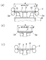
縦横の寸法がそれぞれa、bであるワーク5の四辺を加工する場合、まず側辺板10の側辺相互の間隔Wがa−2dとなるように側辺板10を移動する。ここでdは、加工時に必要なワーク側辺5a、5bの側辺板10の側辺10bからの突出量である。この状態でワーク5をテーブル8上に載せて、幅寸法がaとなる方向の側辺5bを基台1と工具4との当該側辺方向の相対移動により加工する。次にワーク5を側辺板10上から開放し、中心板9上に保持した状態で旋回装置2により中心板9を90度旋回する。この旋回の間に側辺板10をその側辺間隔Wがb−2dとなる位置に移動し、工具4も新たな加工幅bに対応する位置に移動する。この旋回及び移動が終了した後、基台1と工具4とを相対移動(復帰移動)することにより、ワークの他方の側辺5aを加工する。
When machining the four sides of the
この種の側辺加工装置では、ワーク5をテーブル8に固定する手段として負圧による吸着構造が採用されている。すなわち、テーブル面上に負圧源に連通した多数の吸着孔を設けておき、この吸着孔に負圧を作用させてワーク5をテーブル8上に吸着保持する。側辺板10からのワーク5の開放は、この吸着孔に作用している負圧を開放することによって行われる。このとき、吸着孔からワークに向けて空気を噴出するようにすれば、ワーク5は側辺板10の上面から浮上する。また、側辺板10を中心板9に対して相対的に下降すれば、ワーク5は側辺板10の上面から離隔する。この浮上ないし離隔状態で中心板9を旋回してワーク5を回動すれば、回動時におけるワーク5の裏面と側辺板10との摺接による傷付き等を防止できる。
In this type of side processing apparatus, a suction structure using negative pressure is adopted as means for fixing the
上記の説明から理解されるように、この発明の方法及び装置では、加工しようとするワークの側辺部を支持する側辺板10を各加工時におけるワークの幅方向寸法a又はbに合せて設定できるようにし、かつこの側辺板は旋回させないで、ワーク5を中心板9のみで旋回させるようにしたので、ワークの大小及び縦横比の変化のいずれにも対応してワーク5の側辺5a、5bを最適なテーブルからの突出量dを確保した状態で側辺加工を行うことができる。この発明の方法及び装置では、寸法と縦横比の同じワークを連続的に加工するとき、加工する辺の方向が変わるたびに側辺板10の側辺幅Wを変更する操作が必要であるが、この操作はワークの旋回中又は加工装置へのワークの搬入搬出中に行うことができるので、加工能率を低下させるおそれはない。かえって大きさや縦横比の異なるワークが混在していても、加工能率を低下させることなく柔軟に対応できるという特徴がある。
As understood from the above description, in the method and apparatus of the present invention, the
以下、図面を参照してこの発明の実施形態を説明する。図1は、この発明の加工方法の説明図、図2ないし図5は、上記加工方法を実現するための基台上へのテーブルの装着構造を示した図である。図2ないし図5において、1は基台、2は旋回装置、3は基台1上に設けられた広狭装置、7は広狭装置の移動台、8は中心板9と2枚の側辺板10とからなるテーブル、11は側辺板10と移動台7との間に介装されている昇降装置である。
Embodiments of the present invention will be described below with reference to the drawings. FIG. 1 is an explanatory view of a processing method according to the present invention, and FIGS. 2 to 5 are views showing a structure for mounting a table on a base for realizing the processing method. 2 to 5, 1 is a base, 2 is a swivel device, 3 is a wide and narrow device provided on the
図の基台1は、下部に移動ガイド12を備えたテーブル移動型のもので、図3に想像線で示す矢印A方向のガイド13に沿って往復移動する。旋回装置2は、基台1の下部に駆動機構を備え、その旋回シャフト14が基台1の中央上面に突出している。15は旋回装置の機構部分を覆っているカバーである。
The
広狭装置6は、旋回シャフト14を挟む基台1の上面両側に、そのガイド方向(広狭方向)を基台1の送り方向矢印Aと直行する方向にして装着されている。広狭装置6は、直線ガイド16とこれに平行な送りねじ17と、この送りねじを回転駆動するサーボモータ18とを備えており、前後2本の送りねじ17は、1台のサーボモータ18によりそれぞれの同期ベルト19を介して同期駆動されている。送りねじ17は、その長手中心20の両側でねじ方向が逆になっており、各送りねじ17の両側に螺合連結された移動台7Lと7Rとは、同期して近接又は離隔移動する。各送りねじ17は、それぞれの直線ガイド16の上方に位置して、中央部と両端部が軸支されており、移動台7は、この中央と端の軸支部の間で送りねじ17に螺合連結されて直線ガイド16に沿って移動する。
The wide /
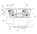
テーブルの中心板9は円板状で、旋回シャフト14の上端に固定されている。側辺板10は、内側中央に中心板9との干渉を避ける半円状の切欠10aを設けた短冊状で、広狭装置の移動台7に基台1の送り方向前後に配置した一対の昇降装置11を介して装着されている。中心板9及び側辺板10の上面には、ワークを吸着するための多数の吸着孔が設けられているが、周知構造であるので図には示してない。側辺板10の側辺10bは、下方を斜めに削がれたエッジ状となっている。これはワークの側辺を加工する工具との干渉を避けるためである。
The
昇降装置11は、各側辺板10につき、基台1の送り方向前後に設けられており、各昇降装置は、側辺板10の垂直方向の移動を案内するガイドロッド21と昇降駆動用のシリンダ22とを備えている。ガイドロッド21は、移動台7の上面から上方に延びる逆L形のブラケット23の上部と移動台上面との間に装架されており、シリンダ22は、逆L形のブラケット23の上部下面にシリンダのヘッドエンド側を固定して装着されている。すなわち、昇降シリンダ22のロッド24は、下方に向いて伸長する。この構造に対応して、側辺板10の下面から下方に延びるL形ブラケットの下辺先端にガイドロッド21に摺動自在に嵌合するガイドスリーブ25が固定され、当該下辺部に昇降シリンダのロッド24が連結されている。すなわち、シリンダロッド24が伸長すると、側辺板10が下降する(図4参照)。
The elevating
2枚の側辺板10をそれぞれ支持する各2個の昇降装置11は、基台1の中心から逆方向にずらした位置に設けられて、テーブル8を側面から見たときに、互い違いになるように配置されている。これは移動台7と側辺板10とを繋ぐ昇降装置11の部分をできるだけ側辺板10の内側に配置して、側辺板10の下方に加工のための工具が入り込む空間26(図1参照)を確保すると共に、2枚の側辺板10相互を接近させたときのテーブル幅Wをできるだけ小さくして加工可能なワークの寸法範囲を大きくするためである。
The two
次に上記のようなテーブル装着構造を備えた側辺加工装置におけるワーク5の加工手順を図1を参照して説明する。図中、5はワーク、4は側辺加工用の工具である。
Next, the processing procedure of the
まず、両側辺板10によって規定されるテーブル幅Wを第1工程で加工するワークの幅aに対してW=a−2dとなるように側辺板10の位置をNC装置の指令に基づくサーボモータ18の回転により設定し、ワーク5をテーブル8に載せて負圧で吸引して固定する(図1(a))。このとき工具4もワーク幅aに対応した位置へ移動するが、この動作は従来装置と同じである。
First, the position of the
次に基台1を矢印A方向に移動することにより、定位置で回転する工具4との間でワーク5を送って、幅寸法aに対応する側の側辺5bの加工を行う。
Next, by moving the
側辺5bの加工が終了したら、中心板9によるワークの吸着保持を保持したまま、側辺板10の吸着を開放し、昇降装置11で側辺板10を下降してワーク5を側辺板10から離隔させる。この状態で中心板9を旋回装置2で90度旋回させると共に、側辺板10を旋回後のワークの幅寸法bに合せた位置、すなわちテーブル幅がb−2dとなるようにサーボモータ18を回転して、両側辺板10を移動する(図1(b))。その後、昇降装置11で側辺板10を元の高さに復帰する。このとき工具4も第2工程時におけるワーク幅bに対応する位置に移動する。
When the processing of the
この状態でワーク5を再び側辺板10上に吸着保持して基台を逆方向に移動させて、第2工程時の側辺5aを加工する(図1(c))。加工が終了したら、中心板9及び側辺板10の吸着を開放して加工済ワークを搬出し、次に加工されるワークを搬入する。このワークの搬出搬入の間に側辺板10及び工具4を移動して、新たに搬入されるワークの幅に合せてテーブル幅Wと工具位置とを設定する。この動作を繰り返すことにより、ワーク5の四辺の加工を連続的に行ってゆく。
In this state, the
1 基台
2 旋回装置
4 面取り砥石
5 ワーク
6 広狭装置
8 テーブル
9 中心板
10 側辺板
10b 側辺
11 昇降装置
DESCRIPTION OF
10 Side plate
10b side
11 Lifting device
Claims (3)
ワークの吸着手段を備えたテーブル(8)と、
このテーブルを挟んで対向する工具(4)とを備え、この工具の対向方向と直交する送り方向に前記基台を相対移動させることにより、前記テーブルに固定されたワーク(5)の両側辺を加工する側辺加工装置において、
前記テーブルが、前記旋回装置で支持された中心板(9)と、対向する前記工具のそれぞれの側に分割されて基台(1)上に前記旋回装置を介さないで配設された一対の側辺板(10)とを備え、この中心板及び一対の側辺板に前記吸着手段を備えさせると共に、前記一対の側辺板を中心板を挟んで同期近接離隔させる拡狭装置(6)と、中心板(9)によるワークの吸着を保持したまま側辺板(10)の吸着を開放する手段とを備えていることを特徴とする、側辺加工装置。 A base (1) with a swivel device (2);
A table (8) equipped with a workpiece suction means;
A tool (4) facing the table, and moving the base relative to the feed direction perpendicular to the facing direction of the tool, thereby moving both sides of the work (5) fixed to the table. In the side processing machine to process,
The table is divided into a center plate (9) supported by the swivel device and the respective sides of the opposed tool, and a pair of tables arranged on the base (1) without the swivel device interposed therebetween. A widening device (6) including a side plate (10) , the center plate and the pair of side plates are provided with the suction means, and the pair of side plates are spaced closely together with the center plate interposed therebetween. And a side processing apparatus comprising: means for releasing suction of the side plate (10) while holding suction of the workpiece by the center plate (9).
Priority Applications (1)
| Application Number | Priority Date | Filing Date | Title |
|---|---|---|---|
| JP2004147164A JP4037386B2 (en) | 2004-05-18 | 2004-05-18 | Work side processing method and apparatus |
Applications Claiming Priority (1)
| Application Number | Priority Date | Filing Date | Title |
|---|---|---|---|
| JP2004147164A JP4037386B2 (en) | 2004-05-18 | 2004-05-18 | Work side processing method and apparatus |
Related Child Applications (1)
| Application Number | Title | Priority Date | Filing Date |
|---|---|---|---|
| JP2007195636A Division JP2007276114A (en) | 2007-07-27 | 2007-07-27 | Work side machining method |
Publications (2)
| Publication Number | Publication Date |
|---|---|
| JP2005329471A JP2005329471A (en) | 2005-12-02 |
| JP4037386B2 true JP4037386B2 (en) | 2008-01-23 |
Family
ID=35484451
Family Applications (1)
| Application Number | Title | Priority Date | Filing Date |
|---|---|---|---|
| JP2004147164A Expired - Fee Related JP4037386B2 (en) | 2004-05-18 | 2004-05-18 | Work side processing method and apparatus |
Country Status (1)
| Country | Link |
|---|---|
| JP (1) | JP4037386B2 (en) |
Cited By (1)
| Publication number | Priority date | Publication date | Assignee | Title |
|---|---|---|---|---|
| KR20150134722A (en) * | 2014-05-22 | 2015-12-02 | 주식회사 에스에프에이 | Grinding system and method for flat panel display |
Families Citing this family (19)
| Publication number | Priority date | Publication date | Assignee | Title |
|---|---|---|---|---|
| CN101005921B (en) * | 2004-09-03 | 2010-10-27 | 三星钻石工业股份有限公司 | Polishing apparatus and polishing method |
| JP2007098564A (en) * | 2005-09-08 | 2007-04-19 | Shiraitekku:Kk | Polishing device |
| JP2007210043A (en) * | 2006-02-07 | 2007-08-23 | Nakamura Tome Precision Ind Co Ltd | Side machining apparatus for work |
| JP4854337B2 (en) * | 2006-03-07 | 2012-01-18 | コーニングジャパン株式会社 | Board processing equipment and processing equipment equipped with it |
| KR100725750B1 (en) * | 2006-06-13 | 2007-06-08 | (주)미래컴퍼니 | Glass substrate support table |
| JP4969197B2 (en) * | 2006-10-11 | 2012-07-04 | 中村留精密工業株式会社 | Side processing equipment for plate material |
| JP5252702B2 (en) * | 2008-09-24 | 2013-07-31 | 中村留精密工業株式会社 | Workpiece side processing equipment |
| WO2011016098A1 (en) * | 2009-08-07 | 2011-02-10 | 坂東機工株式会社 | Glass pane working method, and glass pane working apparatus |
| TWI562858B (en) * | 2009-12-16 | 2016-12-21 | Nakamura Tome Precision Ind | Side processing device of workpiece |
| CN102101258B (en) * | 2009-12-18 | 2015-03-11 | 中村留精密工业株式会社 | Side edge processing device of workpiece |
| CN103273394B (en) * | 2013-05-08 | 2015-11-25 | 深圳市华星光电技术有限公司 | A kind of edge polisher and price fixing device thereof |
| CN105856017A (en) * | 2015-01-20 | 2016-08-17 | 北京恒铭悦科技发展有限公司 | Edge grinding device for edge grinding machine |
| CN205555401U (en) | 2016-04-14 | 2016-09-07 | 日东电工株式会社 | Adsorption element and liquid crystal unit adsorb rotary device |
| CN205554727U (en) | 2016-04-14 | 2016-09-07 | 日东电工株式会社 | Adsorption element , liquid crystal unit adsorb mobile device, reach blooming coating line |
| CN106926084A (en) * | 2017-04-28 | 2017-07-07 | 京东方科技集团股份有限公司 | Glass edge milling apparatus |
| CN107322709A (en) * | 2017-06-05 | 2017-11-07 | 安徽东冠器械设备有限公司 | A kind of efficient rectangular plate control system for processing |
| CN110977656A (en) * | 2019-12-12 | 2020-04-10 | 奥士康科技股份有限公司 | PCB pressfitting folded sheet production is with quick edging device |
| CN111993206B (en) * | 2020-08-19 | 2022-06-14 | 安徽荣程玻璃制品有限公司 | Corner polishing device for glass processing |
| CN112658866B (en) * | 2020-12-18 | 2023-06-06 | 安徽普恒光学材料有限公司 | Polishing device for AG glass bright edges |
-
2004
- 2004-05-18 JP JP2004147164A patent/JP4037386B2/en not_active Expired - Fee Related
Cited By (2)
| Publication number | Priority date | Publication date | Assignee | Title |
|---|---|---|---|---|
| KR20150134722A (en) * | 2014-05-22 | 2015-12-02 | 주식회사 에스에프에이 | Grinding system and method for flat panel display |
| KR101712484B1 (en) * | 2014-05-22 | 2017-03-07 | 주식회사 에스에프에이 | Grinding system for flat panel display |
Also Published As
| Publication number | Publication date |
|---|---|
| JP2005329471A (en) | 2005-12-02 |
Similar Documents
| Publication | Publication Date | Title |
|---|---|---|
| JP4037386B2 (en) | Work side processing method and apparatus | |
| JP2007210043A (en) | Side machining apparatus for work | |
| JP2008093778A (en) | Lateral side processing device of plate material | |
| WO2013118438A1 (en) | Machining system, workpiece machining method, and control method | |
| KR100890644B1 (en) | Multipurpose Engraver with V-Cut | |
| JP2017205838A (en) | One-surface polishing device of plate-like substrate | |
| KR20170009060A (en) | Apparatus for changing a workpiece of a turning center | |
| JP2007276114A (en) | Work side machining method | |
| JP4290611B2 (en) | Side processing device | |
| CN117840495A (en) | A special milling machine for gear groove processing | |
| JP5252702B2 (en) | Workpiece side processing equipment | |
| CN102101258B (en) | Side edge processing device of workpiece | |
| JP4401209B2 (en) | Disc peripheral grinding device | |
| JP2003094132A (en) | Work carrying-out method and device in plate material processing machine | |
| CN109968553B (en) | Positioning device for engraving and milling machine | |
| JP5778792B2 (en) | Machining system and control method | |
| WO2019090684A1 (en) | Laser engraving device for mobile phone shell | |
| KR101133598B1 (en) | The glass processing apparatus for touch screen panel | |
| JPH0523935A (en) | Compound laser beam machine | |
| JPH06218648A (en) | Board reversing device for printed circuit board drilling machine | |
| JP6514247B2 (en) | Manufacturing method, workpiece holding device and processing device | |
| JP7360574B1 (en) | Jig equipment and jig unit | |
| KR100478101B1 (en) | V grove processing machine | |
| CN217316460U (en) | Backing plate of laser cutting machine | |
| JPH04313432A (en) | Auxiliary work clamp device for plate working machine |
Legal Events
| Date | Code | Title | Description |
|---|---|---|---|
| A621 | Written request for application examination |
Free format text: JAPANESE INTERMEDIATE CODE: A621 Effective date: 20070123 |
|
| A871 | Explanation of circumstances concerning accelerated examination |
Free format text: JAPANESE INTERMEDIATE CODE: A871 Effective date: 20070123 |
|
| A975 | Report on accelerated examination |
Free format text: JAPANESE INTERMEDIATE CODE: A971005 Effective date: 20070219 |
|
| A131 | Notification of reasons for refusal |
Free format text: JAPANESE INTERMEDIATE CODE: A131 Effective date: 20070227 |
|
| A521 | Written amendment |
Free format text: JAPANESE INTERMEDIATE CODE: A523 Effective date: 20070427 |
|
| A02 | Decision of refusal |
Free format text: JAPANESE INTERMEDIATE CODE: A02 Effective date: 20070529 |
|
| A521 | Written amendment |
Free format text: JAPANESE INTERMEDIATE CODE: A523 Effective date: 20070727 |
|
| A911 | Transfer of reconsideration by examiner before appeal (zenchi) |
Free format text: JAPANESE INTERMEDIATE CODE: A911 Effective date: 20070803 |
|
| TRDD | Decision of grant or rejection written | ||
| A01 | Written decision to grant a patent or to grant a registration (utility model) |
Free format text: JAPANESE INTERMEDIATE CODE: A01 Effective date: 20071002 |
|
| A61 | First payment of annual fees (during grant procedure) |
Free format text: JAPANESE INTERMEDIATE CODE: A61 Effective date: 20071031 |
|
| R150 | Certificate of patent or registration of utility model |
Ref document number: 4037386 Country of ref document: JP Free format text: JAPANESE INTERMEDIATE CODE: R150 Free format text: JAPANESE INTERMEDIATE CODE: R150 |
|
| FPAY | Renewal fee payment (event date is renewal date of database) |
Free format text: PAYMENT UNTIL: 20101109 Year of fee payment: 3 |
|
| FPAY | Renewal fee payment (event date is renewal date of database) |
Free format text: PAYMENT UNTIL: 20131109 Year of fee payment: 6 |
|
| R250 | Receipt of annual fees |
Free format text: JAPANESE INTERMEDIATE CODE: R250 |
|
| R250 | Receipt of annual fees |
Free format text: JAPANESE INTERMEDIATE CODE: R250 |
|
| R250 | Receipt of annual fees |
Free format text: JAPANESE INTERMEDIATE CODE: R250 |
|
| LAPS | Cancellation because of no payment of annual fees |