JP4341908B2 - Pixel clock and pulse modulation signal generation apparatus, optical scanning apparatus, and image forming apparatus - Google Patents
Pixel clock and pulse modulation signal generation apparatus, optical scanning apparatus, and image forming apparatus Download PDFInfo
- Publication number
- JP4341908B2 JP4341908B2 JP2004001982A JP2004001982A JP4341908B2 JP 4341908 B2 JP4341908 B2 JP 4341908B2 JP 2004001982 A JP2004001982 A JP 2004001982A JP 2004001982 A JP2004001982 A JP 2004001982A JP 4341908 B2 JP4341908 B2 JP 4341908B2
- Authority
- JP
- Japan
- Prior art keywords
- data
- pixel
- pixel clock
- clock
- modulation signal
- Prior art date
- Legal status (The legal status is an assumption and is not a legal conclusion. Google has not performed a legal analysis and makes no representation as to the accuracy of the status listed.)
- Expired - Fee Related
Links
Images


Classifications
-
- H—ELECTRICITY
- H04—ELECTRIC COMMUNICATION TECHNIQUE
- H04N—PICTORIAL COMMUNICATION, e.g. TELEVISION
- H04N1/00—Scanning, transmission or reproduction of documents or the like, e.g. facsimile transmission; Details thereof
- H04N1/04—Scanning arrangements, i.e. arrangements for the displacement of active reading or reproducing elements relative to the original or reproducing medium, or vice versa
- H04N1/047—Detection, control or error compensation of scanning velocity or position
- H04N1/053—Detection, control or error compensation of scanning velocity or position in main scanning direction, e.g. synchronisation of line start or picture elements in a line
-
- G—PHYSICS
- G06—COMPUTING OR CALCULATING; COUNTING
- G06K—GRAPHICAL DATA READING; PRESENTATION OF DATA; RECORD CARRIERS; HANDLING RECORD CARRIERS
- G06K15/00—Arrangements for producing a permanent visual presentation of the output data, e.g. computer output printers
- G06K15/02—Arrangements for producing a permanent visual presentation of the output data, e.g. computer output printers using printers
- G06K15/12—Arrangements for producing a permanent visual presentation of the output data, e.g. computer output printers using printers by photographic printing, e.g. by laser printers
- G06K15/1204—Arrangements for producing a permanent visual presentation of the output data, e.g. computer output printers using printers by photographic printing, e.g. by laser printers involving the fast moving of an optical beam in the main scanning direction
- G06K15/1219—Detection, control or error compensation of scanning velocity or position, e.g. synchronisation
-
- H—ELECTRICITY
- H04—ELECTRIC COMMUNICATION TECHNIQUE
- H04N—PICTORIAL COMMUNICATION, e.g. TELEVISION
- H04N1/00—Scanning, transmission or reproduction of documents or the like, e.g. facsimile transmission; Details thereof
- H04N1/04—Scanning arrangements, i.e. arrangements for the displacement of active reading or reproducing elements relative to the original or reproducing medium, or vice versa
- H04N1/113—Scanning arrangements, i.e. arrangements for the displacement of active reading or reproducing elements relative to the original or reproducing medium, or vice versa using oscillating or rotating mirrors
- H04N1/1135—Scanning arrangements, i.e. arrangements for the displacement of active reading or reproducing elements relative to the original or reproducing medium, or vice versa using oscillating or rotating mirrors for the main-scan only
-
- H—ELECTRICITY
- H04—ELECTRIC COMMUNICATION TECHNIQUE
- H04N—PICTORIAL COMMUNICATION, e.g. TELEVISION
- H04N1/00—Scanning, transmission or reproduction of documents or the like, e.g. facsimile transmission; Details thereof
- H04N1/04—Scanning arrangements, i.e. arrangements for the displacement of active reading or reproducing elements relative to the original or reproducing medium, or vice versa
- H04N1/12—Scanning arrangements, i.e. arrangements for the displacement of active reading or reproducing elements relative to the original or reproducing medium, or vice versa using the sheet-feed movement or the medium-advance or the drum-rotation movement as the slow scanning component, e.g. arrangements for the main-scanning
-
- H—ELECTRICITY
- H04—ELECTRIC COMMUNICATION TECHNIQUE
- H04N—PICTORIAL COMMUNICATION, e.g. TELEVISION
- H04N2201/00—Indexing scheme relating to scanning, transmission or reproduction of documents or the like, and to details thereof
- H04N2201/024—Indexing scheme relating to scanning, transmission or reproduction of documents or the like, and to details thereof deleted
- H04N2201/02406—Arrangements for positioning elements within a head
- H04N2201/02439—Positioning method
-
- H—ELECTRICITY
- H04—ELECTRIC COMMUNICATION TECHNIQUE
- H04N—PICTORIAL COMMUNICATION, e.g. TELEVISION
- H04N2201/00—Indexing scheme relating to scanning, transmission or reproduction of documents or the like, and to details thereof
- H04N2201/04—Scanning arrangements
- H04N2201/047—Detection, control or error compensation of scanning velocity or position
- H04N2201/04701—Detection of scanning velocity or position
- H04N2201/0471—Detection of scanning velocity or position using dedicated detectors
-
- H—ELECTRICITY
- H04—ELECTRIC COMMUNICATION TECHNIQUE
- H04N—PICTORIAL COMMUNICATION, e.g. TELEVISION
- H04N2201/00—Indexing scheme relating to scanning, transmission or reproduction of documents or the like, and to details thereof
- H04N2201/04—Scanning arrangements
- H04N2201/047—Detection, control or error compensation of scanning velocity or position
- H04N2201/04701—Detection of scanning velocity or position
- H04N2201/04732—Detecting at infrequent intervals, e.g. once or twice per line for main-scan control
-
- H—ELECTRICITY
- H04—ELECTRIC COMMUNICATION TECHNIQUE
- H04N—PICTORIAL COMMUNICATION, e.g. TELEVISION
- H04N2201/00—Indexing scheme relating to scanning, transmission or reproduction of documents or the like, and to details thereof
- H04N2201/04—Scanning arrangements
- H04N2201/047—Detection, control or error compensation of scanning velocity or position
- H04N2201/04701—Detection of scanning velocity or position
- H04N2201/04744—Detection of scanning velocity or position by detecting the scanned beam or a reference beam
-
- H—ELECTRICITY
- H04—ELECTRIC COMMUNICATION TECHNIQUE
- H04N—PICTORIAL COMMUNICATION, e.g. TELEVISION
- H04N2201/00—Indexing scheme relating to scanning, transmission or reproduction of documents or the like, and to details thereof
- H04N2201/04—Scanning arrangements
- H04N2201/047—Detection, control or error compensation of scanning velocity or position
- H04N2201/04753—Control or error compensation of scanning position or velocity
- H04N2201/04758—Control or error compensation of scanning position or velocity by controlling the position of the scanned image area
- H04N2201/04767—Control or error compensation of scanning position or velocity by controlling the position of the scanned image area by controlling the timing of the signals, e.g. by controlling the frequency o phase of the pixel clock
- H04N2201/04781—Controlling the phase of the signals
- H04N2201/04784—Controlling the phase of the signals using one or more clock signals selected from a number of clock signals of different phases
-
- H—ELECTRICITY
- H04—ELECTRIC COMMUNICATION TECHNIQUE
- H04N—PICTORIAL COMMUNICATION, e.g. TELEVISION
- H04N2201/00—Indexing scheme relating to scanning, transmission or reproduction of documents or the like, and to details thereof
- H04N2201/04—Scanning arrangements
- H04N2201/047—Detection, control or error compensation of scanning velocity or position
- H04N2201/04753—Control or error compensation of scanning position or velocity
- H04N2201/04794—Varying the control or compensation during the scan, e.g. using continuous feedback or from line to line
Landscapes
- Engineering & Computer Science (AREA)
- Physics & Mathematics (AREA)
- General Physics & Mathematics (AREA)
- Signal Processing (AREA)
- Optics & Photonics (AREA)
- General Engineering & Computer Science (AREA)
- Multimedia (AREA)
- Theoretical Computer Science (AREA)
- Facsimile Scanning Arrangements (AREA)
- Laser Beam Printer (AREA)
- Mechanical Optical Scanning Systems (AREA)
- Facsimile Heads (AREA)
- Facsimile Image Signal Circuits (AREA)
Description
本発明は、レーザプリンタ、デジタル複写機、その他、広く画像形成装置における画素クロックの生成およびレーザ駆動信号としてのパルス変調信号の生成技術に関し、詳しくは、画素クロックおよびパルス変調信号のきめ細かな制御を実現する画素クロックおよびパルス変調信号生成装置、並びに、それを備えた光走査装置、画像形成装置に関する。 The present invention relates to a technology for generating a pixel clock and a pulse modulation signal as a laser drive signal in a wide range of image forming apparatuses such as a laser printer, a digital copying machine, and more specifically, a fine control of a pixel clock and a pulse modulation signal. The present invention relates to a pixel clock and pulse modulation signal generation device to be realized, and an optical scanning device and an image forming device including the device.
レーザプリンタ、デジタル複写機等の画像形成装置の一般的構成を図16に示す。図16において、半導体レーザユニット1001から発光されたレーザ光は、回転するポリゴンミラー1002によりスキャンされ、走査レンズ1003を介して被走査媒体である感光体1004上に光スポットを形成し、その感光体1004を露光して静電潜像を形成する。このとき、1ライン毎に、フォトディテクタ1005の出力信号に基づいて、1ライン毎、位相同期のとられた画像クロック(画素クロック)を生成して画像処理ユニット1006とレーザ駆動回路1007へ供給する。このようにして、半導体レーザユニット1001は、画像処理ユニット1006により生成された画像データと位相同期回路1009により1ライン毎に位相が設定された画像クロックに従い、半導体レーザの発光時間をコントロールすることにより、被走査媒体1004上の静電潜像をコントロールする。
FIG. 16 shows a general configuration of an image forming apparatus such as a laser printer or a digital copying machine. In FIG. 16 , the laser light emitted from the
このような走査光学系において、ポリゴンスキャナ等の偏向器の偏向反射面の回転軸からの距離のばらつきは、被走査面上を走査する光スポット(走査ビーム)の走査速度ムラを発生させる。この走査速度ムラは画像の揺らぎとなり画像品質の劣化となる。高品位の画質を要求する場合は走査ムラの補正を行う必要がある。 In such a scanning optical system, variation in the distance from the rotation axis of the deflecting reflection surface of a deflector such as a polygon scanner causes uneven scanning speed of a light spot (scanning beam) that scans the surface to be scanned. This uneven scanning speed causes image fluctuations and image quality degradation. When high quality image quality is required, it is necessary to correct scanning unevenness.
さらに、マルチビーム光学系の場合、各発光源の発振波長に差があると、走査レンズの色収差が補正されていない光学系の場合に露光位置ずれが発生し、各発光源に対応するスポットが被走査媒体上を走査する時の走査幅は、発光源ごとに差が生じてしまい、画像品質の劣化の要因になってしまうため、走査幅の補正を行う必要がある。 Further, in the case of a multi-beam optical system, if there is a difference in the oscillation wavelength of each light source, an exposure position shift occurs in the case of an optical system in which the chromatic aberration of the scanning lens is not corrected, and a spot corresponding to each light source is generated. The scanning width at the time of scanning on the scanning medium is different for each light source, which causes deterioration in image quality. Therefore, it is necessary to correct the scanning width.
従来、走査ムラ等の補正を行う技術としては、基本的に画素クロックの周波数を変化させて、走査線に沿った光スポット位置を制御する方法が知られている(例えば、特許文献1、特許文献2)。また、画素クロックの位相を制御し、走査のバラツキを補正する方法もある(例えば、特許文献3)。さらには、レーザ駆動信号として、所望パターンのパルス変調信号を任意に生成し、動作速度が早い場合でも、画像のきめ細かな高階調性を実現する方法もある(例えば、特許文献4)。
Conventionally, as a technique for correcting scanning unevenness or the like, a method of controlling a light spot position along a scanning line by basically changing a frequency of a pixel clock is known (for example,
しかしながら、画素クロックの周波数を変化させる従来方式(周波数変調方式)は、一般に画素クロック制御部の構成が複雑であり、かつ、その複雑さは周波数変調幅が微小になるにつれて増大するため、きめ細かな制御ができないという問題がある。また、画素クロックの位相を制御する従来方式や所望パターンのパルス変調信号を生成する従来方式は、それぞれが個別に制御され、高精度に1画素の長さを制御できないという問題がある。 However, the conventional method (frequency modulation method) for changing the frequency of the pixel clock generally has a complicated configuration of the pixel clock control unit, and the complexity increases as the frequency modulation width becomes minute. There is a problem that it cannot be controlled. Further, the conventional method for controlling the phase of the pixel clock and the conventional method for generating a pulse modulation signal of a desired pattern are individually controlled, and there is a problem that the length of one pixel cannot be controlled with high accuracy.
本発明の目的は、1画素の長さが制御可能とし、高精度に走査幅の揺らぎを補正できる画素クロック及びパルス変調信号生成装置、並びに、それを備えた光走査装置、画像形成装置を提供することにある。 SUMMARY OF THE INVENTION An object of the present invention is to provide a pixel clock and pulse modulation signal generation device capable of controlling the length of one pixel and correcting a fluctuation in scanning width with high accuracy, and an optical scanning device and an image forming device provided with the same. There is to do.
本発明の画素クロック及びパルス変調信号生成装置は、高周波クロックを生成する高周波クロック生成手段と、画素の長さを指示する画素制御データに基づいて画素クロックの位相シフト量を指示する位相データを生成するとともに、画像データに対応した所望のビットパターンを表す変調データを生成し、前記画素制御データに基づいて前記変調データの長さを変化させる変調データ生成手段と、前記高周波クロックと前記位相データと水平同期信号とに基づいて画素クロックを生成する画素クロック生成手段と、前記変調データを入力し、前記画素クロックと高周波クロックに基づいて、前記位相データで指示された画素クロックの位相シフト量に応じた長さのシリアルパルス列のパルス変調信号を出力するシリアル変調信号生成手段とを有することを基本とする。 The pixel clock and pulse modulation signal generation device according to the present invention generates high-frequency clock generation means for generating a high-frequency clock and phase data for instructing the phase shift amount of the pixel clock based on pixel control data for instructing the pixel length. And generating modulation data representing a desired bit pattern corresponding to the image data, and changing the length of the modulation data based on the pixel control data, the high-frequency clock, the phase data, A pixel clock generating unit configured to generate a pixel clock based on a horizontal synchronization signal; and the modulation data is input, and the phase shift amount of the pixel clock indicated by the phase data is determined based on the pixel clock and the high frequency clock. Serial modulation signal generating means for outputting a pulse modulation signal of a serial pulse train having a predetermined length; Basic to that it has.
本発明によれば、画像処理装置において、高精度に1画素の長さを制御可能とすることができ、高精度に走査幅の揺らぎを補正できる。 According to the present invention, in the image processing apparatus, the length of one pixel can be controlled with high accuracy, and the fluctuation of the scanning width can be corrected with high accuracy.
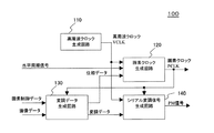
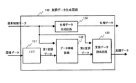
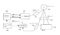
図1に、本発明による画素クロック生成及びパルス変調信号生成装置を適用した画像形成システムの全体構成例を示す。図1において、100は本発明による画素クロック及びパルス変調信号生成装置であり、高周波クロック生成部110、画素クロック生成部120、変調データ生成部130及びレーザ駆動信号部(シリアル変調信号生成部)140からなる。200はレーザ駆動部、300は走査光学系、400はドット位置ずれ検出・制御部、500は画像処理部である。画素クロック生成部120で生成された画素クロックは、変調データ生成部130、レーザ駆動信号生成部140、ドット位置ずれ検出・制御部400、画像処理部500等に供給される。
FIG. 1 shows an overall configuration example of an image forming system to which a pixel clock generation and pulse modulation signal generation apparatus according to the present invention is applied. In FIG. 1,
走査光学系300では、半導体レーザ301からのレーザ光は、コリメータレンズ302、シリンダーレンズ303を通り、ポリゴンミラー304によりスキャン(走査)され、fθレンズ306を通り、ハーフミラー310で反射(一部透過)し、トロイダルレンズ307を通り、感光体305に入射することにより、感光体305上の被走査面上に画像(静電潜像)を形成する。この走査レーザ光のハーフミラー310での透過光の始点、終点を、被走査面上と時間的相関性を持つ被検出面上に配置したフォトディテクタA308、フォトディテクタB309により検出し、水平同期信号1、2としてドット位置ずれ検出・制御部400に入力する。ドット位置ずれ検出・制御部400では、フォトディテクタA308、フォトディテクタB309の間をレーザ光が走査される時間を測定し、あらかじめ定めた基準の時間と比較するなどしてずれ量を求め、そのずれ量を補正するため、画素の長さを指示する画素制御データを生成し、画素クロックに同期して変調データ生成部130に与える。また、画像処理部500からは、画像処理された画像データが、画素クロックに同期して変調データ生成部に与えられる。変調データ生成部130では、画素制御データと画像データに基づいて、高周波クロックと画素クロックの遷移タイミングを指示する位相データ、変調データを生成し、画素クロックに同期して、位相データは画素クロック生成部120に、変調データはレーザ駆動信号生成部140に、それぞれ出力する。高周波クロック生成部110は画素クロック、パルス変調信号(PM信号)の基準となる高周波クロックVCLKを生成し出力する。画素クロック生成部120では、高周波クロックVCLKと位相データ基づいて、周期が変化する画素クロックを生成する。この画素クロックは、水平同期信号1に同期して出力される。レーザ駆動信号生成部140では、高周波クロックVCLK、画素クロックPCLK、変調データからシリアルのパルス変調信号(PM信号)を生成し、レーザ駆動部を介して半導体レーザ301を駆動する。以後、このレーザ駆動信生成部140をシリアル変調信号生成部(回路)と称すことにする。
In the scanning
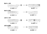
後述するように、変調データ生成部130では、画素を長くする場合、変調データにデータを追加し、画素を短くする場合、変調データのデータを削除する。これにより、シリアル変調信号生成部140から出力されるシリアルのパルス変調信号は、1画素の長さを変化することができるので、走査速度ムラやドットの位置ずれ等を補正することが可能となり、感光体305には走査幅揺らぎのない画像を形成することが出来る。
As will be described later, the modulation
図2に本発明にかかる画素クロック及びパルス変調信号生成装置の一実施例の構成図を示す。図2は、図1中のブロック100の部分を一部表現を変えて示したものである(例えば、高周波クロック生成部を高周波クロック生成回路と変更する等)。
FIG. 2 shows a block diagram of an embodiment of a pixel clock and pulse modulation signal generating apparatus according to the present invention. FIG. 2 shows a part of the
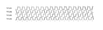
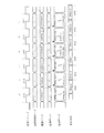
図2において、高周波クロック生成回路110は、画素クロックPCLK、パルス変調信号(PM信号)の基準となる高周波クロックVCLKを生成する。該高周波クロック生成回路110では、例えば、図3に示すような1周期の1/4ずつ位相のずれた4相の高周波クロックVCLK1〜VCLK4を生成し、VCLK1だけあるいはVCLK1とVCLK3を画素クロック生成回路120に与え、VCLK1〜VCLK4全てをシリアル変調信号生成回路140に与える。
In FIG. 2, a high frequency
画素クロック生成回路120では、高周波クロック生成回路110からの高周波クロックVCLK(例えば、VCLK1)、フォトデイテククタA308で検出された水平同期信号1、変調データ生成回路130からの位相データから画素クロックPCLKを生成する。画素クロックPCLKは水平同期信号1に同期して出力され、また、位相データによりPCLKの1クロックごとにその周期が変化して出力される。図4及び図5に、画素クロック生成回路120で生成される画素クロックの一例を示す。図4及び図5では、画素クロックPCLKは通常の場合、高周波クロックVCLKを8分周したクロックとして示している。
In the pixel
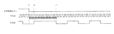
図4には、高周波クロックVCLKと水平同期信号1と画素クロックPCLKの関係を示す。水平同期信号1が立ち下がった(図4のイ)ことにより、画素クロックPCLKが一時“H”固定の状態となる(図4のロ)。そして、水平同期信号1が立ち下がってからある設定した回数(ここでは20回)のVCLKの変化のところ(図4のハ)で、画素クロックPCLKが“L”となりクロックが再び出力され始める。このようにすることにより、図4のイとハの間隔は、常にVCLK半周期の精度で一定となる。
FIG. 4 shows the relationship among the high-frequency clock VCLK, the
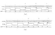
図5には、高周波クロックVCLK及び位相データと画素クロックPCLKの関係を示す。図5における位相データと画素クロックPCLKの位相シフト量の関係を図6に示す。図5(a)において、例えば、イは位相データが“1”であることから、画素クロックPCLKの位相が1/16PCLKだけ進んで、その周期が長くなっている。ロは位相データが“2”であることから、画素クロックPCLKの位相が2/16PCLKだけ進んで、その周期が長くなっている。同様に図5(b)において、ニは位相データが“−1”であることから、画素クロックPCLKの位相が1/16PCLKだけ遅れて、その周期が短くなっている。ホは位相データが−2であることから、画素クロックPCLKの位相が2/16PCLKだけ遅れて、その周期が短くなっている。 FIG. 5 shows the relationship between the high-frequency clock VCLK and phase data, and the pixel clock PCLK. FIG. 6 shows the relationship between the phase data in FIG. 5 and the phase shift amount of the pixel clock PCLK. In FIG. 5A, for example, since the phase data is “1”, the phase of the pixel clock PCLK is advanced by 1/16 PCLK, and the period is long. (B) Since the phase data is “2”, the phase of the pixel clock PCLK is advanced by 2 / 16PCLK, and the period is long. Similarly, in FIG. 5B, since the phase data is “−1”, the phase of the pixel clock PCLK is delayed by 1/16 PCLK, and the cycle is shortened. Since the phase data is -2, the phase of the pixel clock PCLK is delayed by 2 / 16PCLK, and the cycle is shortened.
このように、画素クロック生成回路120では、位相データに従って1クロックごとに周期が長くなったり、短くなったりする画素クロックPCLKを出力する。なお、画素クロック生成回路120には、例えば特開2003−98465に記載のものを使用することができる。
In this manner, the pixel
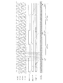
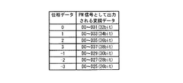
図2において、シリアル変調信号生成回路140は、高周波クロック生成回路110からの高周波クロックVCLKと画素クロック生成回路120からの画素クロックPCLKに基づいて、変調データ生成回路130から与えられるパラレルの変調データ(画像データに対応した所望ピットパターンを表わす)をシリアルに変換しパルス変調信号(PM信号)として出力する。図7に、このPM信号の出力の様子を示す。ここでは高周波クロックとしては図3で示した位相がずれた4つのクロックVCLK1〜VCLK4が与えられ、また、変調データは最大38bit幅を持つデータ(D0〜D37)となっている。パルス変調信号(PM信号)は、変調データの各ビットのデータがVCLK1〜VCLK4の各クロックの立ち上がりで順次出力される。そして、このPM信号は画素クロックPCLKの位相シフト量に応じた長さのパルス列をとる。つまり、図7において、位相データ“0”の時は、変調データのD0〜D31の32bitがシリアルに変換されPM信号として出力され、位相データ”1”の時は変調データのD0〜D33の34bitがシリアルに変換されPM信号として出力される。その他の位相データについても同様である。図8に位相データとPM信号として出力される変調データの対応を示す。なお、シリアル変調信号生成回路140は基本的にはシフトレジスタで構成され、例えば特開2003−103831に記載のものを使用することができる。
In FIG. 2, the serial modulation
図2において、変調データ生成回路130は、ドット位置ずれ検出・制御部400からの1画素の長さを指定する画素制御データと画像処理部500からの画像データをもとに変調データ,位相データを生成し、画素クロックPCLKに同期して出力する。該変調データ生成回路130では、画素制御データに基づき変調データを伸長あるいは縮小する。
In FIG. 2, the modulation
変調データ生成回路130の構成例を図9に示す。ルックアップテーブル(LUT)131は、画像データに対応した所望のビットパターンを表わす変調データを記憶している(例えば、特開2003−103831参照)。まず、画像データをアドレスとして、該LUT131から、入力された画像データに対応する変調データ(これを第1変調データする)を得る。次に、データ伸縮回路132にて、画素制御データに基づき第1変調データにデータの追加、データの削除を行い、第2変調データとして出力する。
A configuration example of the modulation
データの追加、削除は、図10に示すように、第1変調データの最後のbitに追加、あるいは最後のbitを削除してもよいし、第1変調のデータの任意のbitに追加、あるいは任意のbitを削除してもよい。第1変調データの最後のビットに追加あるいは削除する方式は、簡単な構成で1画素の長さを長くあるいは短くすることができ、また、第1変調データの任意のビットに追加あるいは削除する方式は、回路をフレキシブルに構成することができる。また、データの追加、削除を行うbitは変調データのデータパターンに応じて決めるようにしてもよい。この方式は、1画素の濃度変化を小さくして、1画素の長さを長くしたり短くすることができる。さらにデータを追加する場合、その追加するデータパターンはその変調データのデータパターンに依存するようにしてもよい。このようにすれば、例えばその変調データにおける黒のパターンの割合の変化が小さくなるようにすることができる。
変調データ割当回路133にて、画素制御データに基づき、第2変調データの各bitを出力である変調データの各bitに割り当て、変調データとして出力する。同時に、位相データ生成回路134から、画素制御データに基づいて位相データを出力する。図9では、簡単化のため画素クロックPCLKの信号線を省略したが、変調データと位相データは画素クロックに同期して出力される。
As shown in FIG. 10, the addition and deletion of data may be performed by adding to the last bit of the first modulation data, or deleting the last bit, adding to any bit of the data of the first modulation, or Arbitrary bits may be deleted. The method of adding or deleting to the last bit of the first modulation data can make the length of one pixel longer or shorter with a simple configuration, and is the method of adding or deleting to any bit of the first modulation data. The circuit can be configured flexibly. Further, the bit for adding or deleting data may be determined according to the data pattern of the modulation data. In this method, the density change of one pixel can be reduced, and the length of one pixel can be lengthened or shortened. Further, when data is added, the data pattern to be added may depend on the data pattern of the modulation data. In this way, for example, the change in the ratio of the black pattern in the modulation data can be reduced.
Based on the pixel control data, the modulation
図11、図12に変調データ、位相データ出力の様子を示す。ここでは通常、変調データは32bitとして、画素制御データと1画素の長さは図13のようになっているとしている。また、位相データと画素クロックPCLKの位相シフト量は図6のようになっているとしている。 11 and 12 show how modulation data and phase data are output. Here, normally, the modulation data is 32 bits, and the pixel control data and the length of one pixel are as shown in FIG. Further, the phase shift amounts of the phase data and the pixel clock PCLK are as shown in FIG.
まず、図11について説明する。図11は変調データにデータを追加して1画素の長さを伸すケースである。
図11(イ)のクロックでは、画素制御データは“0”なので、画像データDATA(m−1)に対応した第2変調データとしてDPM(m−1)[31:0]の32bitのデータが得られ、変調データD0〜D31それぞれにDPM(m−1)[0]〜DPM(m−1)[31]をロのクロックで出力する。図11(ロ)のクロックでは、画素制御データは“1”なので、画像データDATA(m)に対応した第2変調データとしてDPM(m)[32:0]の33bitのデータが得られる。そして、変調データD0〜D31それぞれにDPM(m)[0]〜DPM(m)[31]をハのクロックで出力し、DPM(m)[32]はニのクロックにおける変調データD0に出力する。図11(ハ)のクロックでは、画素制御データは“0”なので、画像データDATA(m+1)に対応した第2変調データとしてDPM(m+1)[31:0]の32bitのデータが得られる。そして、ここでは変調データD0には先程のDPM(m)[32]を、D1〜D31にはDPM(m+1)[0]〜DPM(m+1)[30]をニのクロックで出力する。DPM(m+1)[31]は、ホのクロックにおける変調データD0に出力する。図11(ニ)のクロックでは、画素制御データは“1”なので、画像データDATA(m+2)に対応した第2変調データとしてDPM(m+2)[32:0]の33bitのデータが得られる。そして、この時位相データとして“1”をホのクロックで出力する。ホのクロックは位相データが”1”であることから位相シフトがおこり、そのクロックは長くなる。そのため変調データ幅も長くなりD0〜D33となる。よってD0には先程のDPM(m+1)[31]を、D1〜D33にDPM(m+2)[0]〜DPM(m+2)[32]をホのクロックで出力する。図11(ホ)のクロックでは、画素制御データは“0”なので、画像データDATA(m+3)に対応した第2変調データとしてDPM(m+3)[31:0]の32bitのデータが得られ、変調データD0〜D31それぞれにDPM(m+3)[0]〜DPM(m+3)[31]をヘのクロックで出力する。
First, FIG. 11 will be described. FIG. 11 shows a case where the length of one pixel is increased by adding data to the modulation data.
The clock of FIG. 11 (b), the pixel control data is so "0", the image data DATA (m-1) DPM as a second modulation data corresponding to (m-1) [31: 0] 32bit data of As a result, DPM (m−1) [0] to DPM (m−1) [31] are output to the modulation data D0 to D31, respectively, with a low clock. Since the pixel control data is “1” in the clock of FIG. 11B, 33-bit data of DPM (m) [32: 0] is obtained as the second modulation data corresponding to the image data DATA (m). Then, DPM (m) [0] to DPM (m) [31] are output to the modulation data D0 to D31 with the clock C, and DPM (m) [32] is output to the modulation data D0 with the second clock. . Since the pixel control data is “0” in the clock of FIG. 11C, 32-bit data of DPM (m + 1) [31: 0] is obtained as the second modulation data corresponding to the image data DATA (m + 1). In this case, DPM (m) [32] is output as the modulated data D0, and DPM (m + 1) [0] to DPM (m + 1) [30] are output as D1 to D31 with the second clock. DPM (m + 1) [31] outputs the modulation data D0 in the clock of E. In the clock of FIG. 11D, since the pixel control data is “1”, 33-bit data of DPM (m + 2) [32: 0] is obtained as the second modulation data corresponding to the image data DATA (m + 2). At this time, “1” is output as the phase data with the clock of E. Since the phase of the clock of E is “1”, a phase shift occurs and the clock becomes longer. Therefore, the modulation data width becomes longer and becomes D0 to D33. Therefore, DPM (m + 1) [31] is output to D0, and DPM (m + 2) [0] to DPM (m + 2) [32] are output to D1 to D33 with the clock of H. In the clock of FIG. 11 (e), since the pixel control data is “0”, 32-bit data of DPM (m + 3) [31: 0] is obtained as the second modulation data corresponding to the image data DATA (m + 3), and the modulation is performed. DPM (m + 3) [0] to DPM (m + 3) [31] are output to the data D0 to D31, respectively, with a high clock.
図11のように位相データ、変調データを出力し、位相データは画素クロック生成回路120に、変調データはシリアル変調信号生成回路140に与えることにより、1/32画素幅で1画素の長さを伸ばすことができる。
As shown in FIG. 11, the phase data and the modulation data are output, and the phase data is supplied to the pixel
次に、図12について説明する。図12は変調データのデータを削除して1画素の長さを短くするケースである。
図12(イ)のクロックでは、画素制御データは“0”なので、画像データDATA(m−1)に対応した第2変調データとしてDPM(m−1)[31:0]の32bitのデータが得られ、変調データD0〜D31それぞれにDPM(m−1)[0]〜DPM(m−1)[31]をロのクロックで出力する。図12(ロ)のクロックでは、画素制御データは“−1”なので画像データDATA(m)に対応した第2変調データとしてDPM(m)[30:0]の31bitのデータが得られる。そして、変調データD0〜D30それぞれにDPM(m)[0]〜DPM(m)[30]を、D31には次の画像データDATA(m+1)に対応する変調データDPM(m+1)[0]をハのクロックで出力する。図12(ハ)のクロックでは、画素制御データは“0”なので、画像データDATA(m+1)に対応した第2変調データとしてDPM(m+1)[31:0]の32bitのデータが得られる。そして、ここではDPM(m+1)[0]は一つ前の変調データD31に出力しているので、D0〜D30にDPM(m+1)[1]〜DPM(m+1)[31]を、D31には次の画像データDATA(m+2)に対応する変調データDPM(m+2)[0]をニのクロックで出力する。図12(ニ)のクロックでは、画素制御データは“−1”なので、画像データDATA(m+2)に対応した第2変調データとしてDPM(m+2)[30:0]の31bitのデータが得られる。そして、この時位相データとして“−1”をホのクロックで出力する。ホのクロックは位相データが“−1”であることから位相シフトがおこりそのクロックは短くなる。そのため変調データ幅も短くなりD0〜D29となる。DPM(m+2)[0]は一つ前の変調データD31に出力しているので、D0〜D29にはDPM(m+2)[1]〜DPM(m+2)[30]をホのクロックで出力する。図12(ホ)のクロックでは、画素制御データは“0”なので、画像データDATA(m+3)に対応した第2変調データとしてDPM(m+3)[31:0]の32bitのデータが得られ、変調データD0〜D31それぞれにDPM(m+3)[0]〜DPM(m+3)[31]をヘのクロックで出力する。
Next, FIG. 12 will be described. FIG. 12 shows a case where the modulation data is deleted to shorten the length of one pixel.
Since the pixel control data is “0” in the clock of FIG. 12A, 32-bit data of DPM (m−1) [31: 0] is obtained as the second modulation data corresponding to the image data DATA (m−1). As a result, DPM (m−1) [0] to DPM (m−1) [31] are output to the modulation data D0 to D31, respectively, with a low clock. In the clock of FIG. 12B, since the pixel control data is “−1”, 31-bit data of DPM (m) [30: 0] is obtained as the second modulation data corresponding to the image data DATA (m). Then, DPM (m) [0] to DPM (m) [30] are respectively stored in the modulation data D0 to D30, and the modulation data DPM (m + 1) [0] corresponding to the next image data DATA (m + 1) is stored in D31. Output with the clock of C. Since the pixel control data is “0” in the clock of FIG. 12C, 32-bit data of DPM (m + 1) [31: 0] is obtained as the second modulation data corresponding to the image data DATA (m + 1). Since DPM (m + 1) [0] is output to the previous modulation data D31 here, DPM (m + 1) [1] to DPM (m + 1) [31] are set to D0 to D30, and D31 is set to D31. Modulation data DPM (m + 2) [0] corresponding to the next image data DATA (m + 2) is output with a second clock. In the clock of FIG. 12D, since the pixel control data is “−1”, 31-bit data of DPM (m + 2) [30: 0] is obtained as the second modulation data corresponding to the image data DATA (m + 2). At this time, “−1” is output as the phase data with the clock of E. Since the phase data of the clock of “e” is “−1”, the phase shift occurs and the clock becomes shorter. Therefore, the modulation data width is also shortened to D0 to D29. Since DPM (m + 2) [0] is output to the previous modulation data D31, DPM (m + 2) [1] to DPM (m + 2) [30] are output to D0 to D29 with the clock of H. In the clock shown in FIG. 12 (e), since the pixel control data is “0”, 32-bit data of DPM (m + 3) [31: 0] is obtained as the second modulation data corresponding to the image data DATA (m + 3). DPM (m + 3) [0] to DPM (m + 3) [31] are output to the data D0 to D31, respectively, with a high clock.
図12のように位相データ、変調データを出力し、位置データは画素クロック生成回路120に、変調データはシリアル変調信号生成回路140に与えることにより、1/32画素幅で1画素の長さを短くすることができる。
As shown in FIG. 12, the phase data and the modulation data are output, the position data is supplied to the pixel
以上のように、実施例では、1画素の長さを1/32画素という細かいステップで、長くしたり短くしたりできるので、ドット位置ずれ補正をより細かい精度で行うことが可能となる。 As described above, in the embodiment, since the length of one pixel can be increased or decreased by a fine step of 1/32 pixel, dot position deviation correction can be performed with finer accuracy.
図14に、本発明の画素クロック及びパルス変調信号生成装置を搭載した光走査装置を示す。光源ユニット601の背面には半導体レーザの制御を司る駆動回路及び画素クロック及びパルス変調信号生成装置が形成されたプリント基板602が装着され、光軸と直交する光学ハウジングの壁面にスプリングにより当接され、調節ネジ603により傾きが合わせられ姿勢が保持される。尚、調節ネジ803はハウジング壁面に形成された突起部に螺合される。光学ハウジング内部には、シリンダレンズ605、ポリゴンミラーを回転するポリゴンモータ608、fθレンズ606、トロイダルレンズ(図示せず)、および折り返しミラー607が各々位置決めされて支持され、また、同期検知センサを実装するプリント基板609は、ハウジング壁面に光源ユニットと同様、外側より装着される。光学ハウジングは、カバー611により上部を封止し、壁面から突出した複数の取付部610にて画像形成装置本体のフレーム部材にネジ固定される。
FIG. 14 shows an optical scanning device equipped with the pixel clock and pulse modulation signal generation device of the present invention. A printed
図15に、図14の光走査装置を搭載した画像形成装置の構成例を示す。被走査面である感光体ドラム701の周囲には感光体を高圧に帯電する帯電チャージャ702、光走査装置700により記録された静電潜像に帯電したトナーを付着して顕像化する現像ローラ703、現像ローラにトナーを供給するトナーカートリッジ704、ドラムに残ったトナーを掻き取り備蓄するクリーニングケース705が配置される。感光体ドラム701へは1面毎に複数ライン同時に潜像記録が行われる。記録紙は給紙トレイ706から給紙コロ707により供給され、レジストローラ対708により副走査方向の記録開始のタイミングに合わせて送りだされ、感光体ドラム701を通過する際に転写チャージク709によってトナーが転写され、定着ローラ710で定着して排紙ローラ711により排紙トレイ712に排出される。
FIG. 15 shows a configuration example of an image forming apparatus equipped with the optical scanning device of FIG. Around the
100 画素クロック及びパルス変調信号生成装置
110 高周波クロック生成部
120 画素クロック生成部
130 変調データ生成部
140 レーザ駆動信号生成部(シリアル変調信号生成部)
200 レーザ駆動部
300 走査光学系
400 ドット位置ずれ検出・制御部
500 画像処理部
100 pixel clock and pulse modulation
200
Claims (12)
画素の長さを指示する画素制御データに基づいて画素クロックの位相シフト量を指示する位相データを生成するとともに、画像データに対応した所望のビットパターンを表す変調データを生成し、前記画素制御データに基づいて前記変調データの長さを変化させる変調データ生成手段と、
前記高周波クロックと前記位相データと水平同期信号とに基づいて画素クロックを生成する画素クロック生成手段と、
前記変調データを入力し、前記画素クロックと高周波クロックに基づいて、前記位相データで指示された画素クロックの位相シフト量に応じた長さのシリアルパルス列のパルス変調信号を出力するシリアル変調信号生成手段と、
を有することを特徴とする画素クロック及びパルス変調信号生成装置。 High-frequency clock generation means for generating a high-frequency clock;
Generating phase data indicating the phase shift amount of the pixel clock based on the pixel control data indicating the pixel length , generating modulation data representing a desired bit pattern corresponding to the image data, and the pixel control data; Modulation data generation means for changing the length of the modulation data based on
Pixel clock generation means for generating a pixel clock based on the high-frequency clock, the phase data, and a horizontal synchronization signal;
Serial modulation signal generating means for inputting the modulation data and outputting a pulse modulation signal of a serial pulse train having a length corresponding to the phase shift amount of the pixel clock indicated by the phase data based on the pixel clock and the high frequency clock When,
A device for generating a pixel clock and a pulse modulation signal, comprising:
前記位相データで指示される画素クロックの位相シフト量に応じて、前記画素制御データに基づいて長さが変化する前記変調データを構成する複数のデータを2つの連続する画素クロックに分けて出力することを特徴とする請求項1に記載の画素クロック及びパルス変調信号生成装置。A plurality of data constituting the modulation data whose length changes based on the pixel control data in accordance with the phase shift amount of the pixel clock indicated by the phase data is divided into two continuous pixel clocks and output. The pixel clock and pulse modulation signal generation device according to claim 1.
前記変調データ生成手段は、前記画素制御データに基づいて、前記変調データの追加あるいは削除を行うことを特徴とする画素クロック及びパルス変調信号生成装置。The pixel clock and pulse modulation signal generation device, wherein the modulation data generation means adds or deletes the modulation data based on the pixel control data.
画素を長くする場合は前記変調データの最後にデータを追加することを特徴とする画素クロック及びパルス変調信号生成装置。An apparatus for generating a pixel clock and pulse modulation signal, wherein when a pixel is lengthened, data is added to the end of the modulation data.
画素を短くする場合は前記変調データの最後のデータを削除することを特徴とする画素クロック及びパルス変調信号生成装置。An apparatus for generating a pixel clock and pulse modulation signal, wherein when the pixel is shortened, the last data of the modulation data is deleted.
画素を長くする場合は前記変調データの任意の位置にデータを追加することを特徴とする画素クロック及びパルス変調信号生成装置。An apparatus for generating a pixel clock and pulse modulation signal, wherein data is added to an arbitrary position of the modulation data when a pixel is lengthened.
画素を短くする場合は前記変調データの任意の位置のデータを削除することを特徴とする画素クロック及びパルス変調信号生成装置。An apparatus for generating a pixel clock and pulse modulation signal, wherein data at an arbitrary position of the modulation data is deleted when a pixel is shortened.
前記変調データにデータを追加する位置は前記変調データのパターンに依存することを特徴とする画素クロック及びパルス変調信号生成装置。A pixel clock and pulse modulation signal generating apparatus, wherein a position at which data is added to the modulation data depends on a pattern of the modulation data.
前記変調データのデータを削除する位置は前記変調データのパターンに依存することを特徴とする画素クロック及びパルス変調信号生成装置。The pixel clock and pulse modulation signal generation device according to claim 1, wherein a position at which the modulation data is deleted depends on a pattern of the modulation data.
前記変調データに追加するデータは前記変調データパターンに依存することを特徴とする画素クロック及びパルス変調信号生成装置。2. A pixel clock and pulse modulation signal generating device according to claim 1, wherein data added to the modulation data depends on the modulation data pattern.
請求項1乃至10のいずれか1項に記載の画素クロック及びパルス変調信号生成装置を有することを特徴とする光走査装置。An optical scanning device comprising the pixel clock and pulse modulation signal generation device according to claim 1.
Priority Applications (3)
| Application Number | Priority Date | Filing Date | Title |
|---|---|---|---|
| JP2004001982A JP4341908B2 (en) | 2004-01-07 | 2004-01-07 | Pixel clock and pulse modulation signal generation apparatus, optical scanning apparatus, and image forming apparatus |
| US11/030,419 US7327379B2 (en) | 2004-01-07 | 2005-01-07 | Pixel clock and pulse-modulation-signal generating device, optical scanner, and image forming apparatus |
| US11/844,854 US7973817B2 (en) | 2004-01-07 | 2007-08-24 | Pixel clock and pulse-modulation-signal generating device, optical scanner, and image forming apparatus |
Applications Claiming Priority (1)
| Application Number | Priority Date | Filing Date | Title |
|---|---|---|---|
| JP2004001982A JP4341908B2 (en) | 2004-01-07 | 2004-01-07 | Pixel clock and pulse modulation signal generation apparatus, optical scanning apparatus, and image forming apparatus |
Publications (2)
| Publication Number | Publication Date |
|---|---|
| JP2005198006A JP2005198006A (en) | 2005-07-21 |
| JP4341908B2 true JP4341908B2 (en) | 2009-10-14 |
Family
ID=34709023
Family Applications (1)
| Application Number | Title | Priority Date | Filing Date |
|---|---|---|---|
| JP2004001982A Expired - Fee Related JP4341908B2 (en) | 2004-01-07 | 2004-01-07 | Pixel clock and pulse modulation signal generation apparatus, optical scanning apparatus, and image forming apparatus |
Country Status (2)
| Country | Link |
|---|---|
| US (2) | US7327379B2 (en) |
| JP (1) | JP4341908B2 (en) |
Families Citing this family (35)
| Publication number | Priority date | Publication date | Assignee | Title |
|---|---|---|---|---|
| JP4341908B2 (en) * | 2004-01-07 | 2009-10-14 | 株式会社リコー | Pixel clock and pulse modulation signal generation apparatus, optical scanning apparatus, and image forming apparatus |
| JP4777720B2 (en) * | 2005-08-24 | 2011-09-21 | 株式会社リコー | Optical writing apparatus, image forming apparatus, optical writing method, computer program, and recording medium |
| JP2007286423A (en) * | 2006-04-18 | 2007-11-01 | Brother Ind Ltd | Optical scanning device, image display device, and retinal scanning image display device |
| JP4790532B2 (en) * | 2006-08-01 | 2011-10-12 | 株式会社リコー | Imaging apparatus and wireless communication partner searching method |
| JP4912071B2 (en) * | 2006-08-04 | 2012-04-04 | 株式会社リコー | Optical scanning apparatus, optical scanning method, image forming apparatus, color image forming apparatus, program, and recording medium |
| JP5001606B2 (en) * | 2006-08-31 | 2012-08-15 | 川崎マイクロエレクトロニクス株式会社 | Timing detection circuit |
| JP4863840B2 (en) * | 2006-10-27 | 2012-01-25 | 株式会社リコー | Pixel forming apparatus, optical scanning apparatus, optical scanning method, image forming apparatus, and color image forming apparatus |
| JP5083867B2 (en) * | 2007-03-02 | 2012-11-28 | 株式会社リコー | Light source driving device, optical scanning device, and image forming apparatus |
| US7995251B2 (en) * | 2007-03-30 | 2011-08-09 | Ricoh Company, Limited | Optical scanning device, optical scanning method, and image forming apparatus |
| US7760223B2 (en) * | 2007-05-14 | 2010-07-20 | Ricoh Company, Ltd. | Optical scan apparatus and image formation apparatus |
| JP4953918B2 (en) * | 2007-05-23 | 2012-06-13 | 株式会社リコー | Light source driving device, optical scanning device, and image forming apparatus |
| JP5354891B2 (en) | 2007-11-22 | 2013-11-27 | キヤノン株式会社 | Image forming apparatus |
| JP2009157014A (en) * | 2007-12-26 | 2009-07-16 | Ricoh Co Ltd | Optical scanning apparatus and image forming apparatus |
| JP5194802B2 (en) * | 2008-01-07 | 2013-05-08 | 株式会社リコー | Light source driving device, optical scanning device, and image forming apparatus |
| JP5006810B2 (en) * | 2008-02-06 | 2012-08-22 | 株式会社リコー | Optical scanning apparatus and image forming apparatus |
| JP2009196226A (en) * | 2008-02-22 | 2009-09-03 | Ricoh Co Ltd | Pulse modulation signal generation unit, light source unit, optical scanner, and image formation apparatus |
| JP2009244843A (en) * | 2008-03-14 | 2009-10-22 | Ricoh Co Ltd | Optical scanning device and color image forming apparatus |
| JP5036634B2 (en) * | 2008-06-10 | 2012-09-26 | 株式会社リコー | Light source device, optical scanning device, and image forming apparatus |
| US8237760B2 (en) * | 2008-08-19 | 2012-08-07 | Ricoh Company, Ltd. | Light-source driving device, optical scanning device, and counting method |
| JP5402072B2 (en) * | 2009-02-23 | 2014-01-29 | 株式会社リコー | Light source driving device, optical scanning device, and image forming apparatus |
| JP5391873B2 (en) * | 2009-06-30 | 2014-01-15 | コニカミノルタ株式会社 | Image forming apparatus |
| JP5805364B2 (en) * | 2009-07-09 | 2015-11-04 | 株式会社リコー | Light source driving device, optical scanning device, and image forming apparatus |
| JP2011066089A (en) | 2009-09-15 | 2011-03-31 | Ricoh Co Ltd | Semiconductor laser control device, and image formation device |
| JP5544887B2 (en) | 2010-01-12 | 2014-07-09 | 株式会社リコー | Optical scanning apparatus and image forming apparatus |
| JP5471569B2 (en) * | 2010-02-18 | 2014-04-16 | 株式会社リコー | Laser driving device, optical scanning device, image forming apparatus, and laser driving method |
| JP2011258796A (en) | 2010-06-10 | 2011-12-22 | Ricoh Co Ltd | Laser driving device, optical scanning apparatus and image forming apparatus |
| JP5836684B2 (en) * | 2011-07-25 | 2015-12-24 | キヤノン株式会社 | Image forming apparatus |
| US8654168B2 (en) | 2011-08-03 | 2014-02-18 | Ricoh Company, Ltd. | Optical scanning device, image forming apparatus, and optical scanning device designing method |
| JP6120655B2 (en) * | 2013-04-18 | 2017-04-26 | キヤノン株式会社 | Image forming apparatus |
| JP6172506B2 (en) | 2013-05-02 | 2017-08-02 | 株式会社リコー | Image forming apparatus and image forming method |
| JP6167654B2 (en) | 2013-05-09 | 2017-07-26 | 株式会社リコー | Image forming apparatus, image forming method, and printed material manufacturing method |
| JP6171547B2 (en) | 2013-05-10 | 2017-08-02 | 株式会社リコー | Image forming apparatus, image forming method, and printed material manufacturing method |
| JP6127712B2 (en) | 2013-05-21 | 2017-05-17 | 株式会社リコー | Light source driving circuit, optical scanning device, and image forming apparatus |
| JP6230466B2 (en) * | 2014-03-31 | 2017-11-15 | キヤノン株式会社 | Image forming apparatus |
| JP6596814B2 (en) | 2014-11-25 | 2019-10-30 | 株式会社リコー | Image forming apparatus |
Family Cites Families (34)
| Publication number | Priority date | Publication date | Assignee | Title |
|---|---|---|---|---|
| US5117243A (en) * | 1990-04-06 | 1992-05-26 | S&R Tech Development, Inc. | Scanner with electronic non-linearity compensation and method of processing image data |
| JP3212200B2 (en) * | 1992-11-27 | 2001-09-25 | 東芝テック株式会社 | Optical scanning device |
| JP3231610B2 (en) * | 1995-12-22 | 2001-11-26 | 富士通株式会社 | Color image forming equipment |
| JPH1067141A (en) | 1996-06-19 | 1998-03-10 | Ricoh Co Ltd | Apparatus for controlling semiconductor laser |
| US6091891A (en) * | 1997-05-09 | 2000-07-18 | Lexmark International, Inc. | Method and apparatus for calibrating delay lines to create gray levels in continuous tone printing |
| JPH11167081A (en) | 1997-09-30 | 1999-06-22 | Eastman Kodak Co | Variable frequency pixel clock |
| US6178031B1 (en) | 1999-12-20 | 2001-01-23 | Xerox Corporation | Raster output scanning system having scan line non-linearity compensation means |
| JP4665375B2 (en) * | 2000-07-28 | 2011-04-06 | 日亜化学工業株式会社 | Display device |
| JP4154856B2 (en) * | 2000-12-28 | 2008-09-24 | コニカミノルタホールディングス株式会社 | Clock generation circuit and image forming apparatus |
| JP3515087B2 (en) | 2001-09-28 | 2004-04-05 | 株式会社リコー | Pulse modulation signal generation circuit, semiconductor laser modulation device, optical scanning device, and image forming device |
| DE60237256D1 (en) * | 2001-03-14 | 2010-09-23 | Ricoh Kk | Light emission modulation with an effective method of producing gray tones in an image |
| JP2003034051A (en) | 2001-07-25 | 2003-02-04 | Ricoh Co Ltd | Pixel clock generation device, optical writing device, and image forming device |
| US6791596B2 (en) * | 2001-06-28 | 2004-09-14 | Ricoh Company, Ltd. | Method and apparatus for image forming capable of effectively generating pixel clock pulses |
| JP3512397B2 (en) | 2001-09-25 | 2004-03-29 | 株式会社リコー | Pixel clock generation circuit and image forming apparatus |
| JP2003015068A (en) | 2001-07-02 | 2003-01-15 | Ricoh Co Ltd | Image forming apparatus and pixel clock generation circuit |
| JP2003279873A (en) | 2002-03-20 | 2003-10-02 | Ricoh Co Ltd | Optical scanning device and image forming apparatus |
| US7271824B2 (en) * | 2001-09-28 | 2007-09-18 | Ricoh Company, Ltd. | Pixel clock generating apparatus, optical writing apparatus using a pixel clock, imaging apparatus, and method for generating pixel clocks |
| JP4323120B2 (en) | 2001-09-28 | 2009-09-02 | 株式会社リコー | Pixel clock generation method, pixel clock generation apparatus, and image forming apparatus |
| JP2003320702A (en) | 2002-04-30 | 2003-11-11 | Ricoh Co Ltd | Imaging method and imaging apparatus |
| US7256815B2 (en) | 2001-12-20 | 2007-08-14 | Ricoh Company, Ltd. | Image forming method, image forming apparatus, optical scan device, and image forming apparatus using the same |
| JP4007807B2 (en) | 2001-12-20 | 2007-11-14 | 株式会社リコー | Optical scanning device and image forming apparatus using the same |
| JP3600228B2 (en) * | 2002-03-01 | 2004-12-15 | 株式会社リコー | Optical scanning device and image forming apparatus |
| JP2003300341A (en) | 2002-04-10 | 2003-10-21 | Ricoh Co Ltd | Pixel clock generation device, laser scanning device, and image forming device |
| JP2003322810A (en) | 2002-05-01 | 2003-11-14 | Ricoh Co Ltd | Pixel clock generation device, optical scanning device, image forming device, and main scanning dot misalignment correction method |
| JP4593884B2 (en) * | 2002-05-10 | 2010-12-08 | キヤノン株式会社 | Laser scanning control device |
| US7283151B2 (en) | 2002-05-27 | 2007-10-16 | Ricoh Company, Ltd. | Pixel clock generation device causing state transition of pixel clock according to detected state transition and phase data indicating phase shift amount |
| JP2003344790A (en) | 2002-05-27 | 2003-12-03 | Ricoh Co Ltd | Pixel clock generation device, laser scanning device, and image forming device |
| JP2004351908A (en) * | 2002-07-31 | 2004-12-16 | Canon Inc | Image forming apparatus and main scanning magnification correction method thereof |
| JP4308495B2 (en) | 2002-09-24 | 2009-08-05 | 株式会社リコー | Optical scanning apparatus and image forming apparatus |
| US6933957B2 (en) | 2002-09-24 | 2005-08-23 | Ricoh Company, Ltd. | Pixel clock generation apparatus, pixel clock generation method, and image forming apparatus capable of correcting main scan dot position shift with a high degree of accuracy |
| JP4462917B2 (en) * | 2003-01-23 | 2010-05-12 | 株式会社リコー | Light beam writing apparatus, image forming apparatus, and image correction method |
| JP4165746B2 (en) | 2003-02-07 | 2008-10-15 | 株式会社リコー | Pixel clock generation circuit and image forming apparatus |
| JP4227817B2 (en) * | 2003-02-28 | 2009-02-18 | 株式会社リコー | Image forming apparatus |
| JP4341908B2 (en) * | 2004-01-07 | 2009-10-14 | 株式会社リコー | Pixel clock and pulse modulation signal generation apparatus, optical scanning apparatus, and image forming apparatus |
-
2004
- 2004-01-07 JP JP2004001982A patent/JP4341908B2/en not_active Expired - Fee Related
-
2005
- 2005-01-07 US US11/030,419 patent/US7327379B2/en not_active Expired - Fee Related
-
2007
- 2007-08-24 US US11/844,854 patent/US7973817B2/en not_active Expired - Fee Related
Also Published As
| Publication number | Publication date |
|---|---|
| US7973817B2 (en) | 2011-07-05 |
| US7327379B2 (en) | 2008-02-05 |
| US20080012933A1 (en) | 2008-01-17 |
| US20050146596A1 (en) | 2005-07-07 |
| JP2005198006A (en) | 2005-07-21 |
Similar Documents
| Publication | Publication Date | Title |
|---|---|---|
| JP4341908B2 (en) | Pixel clock and pulse modulation signal generation apparatus, optical scanning apparatus, and image forming apparatus | |
| JP4336177B2 (en) | Pixel clock generation device, optical scanning device, and image forming device | |
| JP5078836B2 (en) | Optical scanning apparatus and image forming apparatus | |
| JP2007038477A (en) | Pixel clock and pulse modulation signal generation apparatus, optical scanning apparatus, and image forming apparatus | |
| JP2000180747A (en) | Optical scanner | |
| JP3078557B2 (en) | Digital printer | |
| JPH11198435A (en) | Image forming apparatus | |
| US6806894B2 (en) | Image forming apparatus and main scanning scale correcting method therefor | |
| US7652682B2 (en) | Image forming apparatus | |
| US20080018727A1 (en) | Optical beam scanning apparatus, optical beam scanning method, optical beam scanning program, image forming apparatus, image forming method, image forming program | |
| JP5276351B2 (en) | Image forming apparatus | |
| JPH1155472A (en) | Multicolor image forming device | |
| US7433074B2 (en) | Image forming apparatus and image forming method | |
| JP4367840B2 (en) | Pixel clock generation device, optical scanning device, and image forming device | |
| JP2007090758A (en) | Image forming apparatus | |
| US7804514B2 (en) | Light beam scanning apparatus and image forming apparatus | |
| JP4313132B2 (en) | Pixel clock generation circuit, pixel clock and pulse modulation signal generation circuit, optical scanning apparatus, and image forming apparatus | |
| JP2009196226A (en) | Pulse modulation signal generation unit, light source unit, optical scanner, and image formation apparatus | |
| JP4134999B2 (en) | Light emission timing adjustment method, laser scanning device, and image forming apparatus | |
| JP2004354626A (en) | Image forming apparatus and horizontal synchronizing signal generating method in the apparatus | |
| JP2003121770A (en) | Image forming apparatus | |
| JP2006175646A (en) | Image forming system and image forming method | |
| US7436424B2 (en) | Light beam scanning apparatus and image forming apparatus with parallel modulating and driving channels | |
| JP2004286862A (en) | Light beam scanning circuit, light beam scanning device, and image forming apparatus | |
| JP2008225064A (en) | Pixel clock generation apparatus, optical scanning apparatus, and image forming apparatus |
Legal Events
| Date | Code | Title | Description |
|---|---|---|---|
| A621 | Written request for application examination |
Free format text: JAPANESE INTERMEDIATE CODE: A621 Effective date: 20060825 |
|
| A977 | Report on retrieval |
Free format text: JAPANESE INTERMEDIATE CODE: A971007 Effective date: 20090119 |
|
| A131 | Notification of reasons for refusal |
Free format text: JAPANESE INTERMEDIATE CODE: A131 Effective date: 20090128 |
|
| A521 | Written amendment |
Free format text: JAPANESE INTERMEDIATE CODE: A523 Effective date: 20090326 |
|
| TRDD | Decision of grant or rejection written | ||
| A01 | Written decision to grant a patent or to grant a registration (utility model) |
Free format text: JAPANESE INTERMEDIATE CODE: A01 Effective date: 20090701 |
|
| A01 | Written decision to grant a patent or to grant a registration (utility model) |
Free format text: JAPANESE INTERMEDIATE CODE: A01 |
|
| A61 | First payment of annual fees (during grant procedure) |
Free format text: JAPANESE INTERMEDIATE CODE: A61 Effective date: 20090703 |
|
| FPAY | Renewal fee payment (event date is renewal date of database) |
Free format text: PAYMENT UNTIL: 20120717 Year of fee payment: 3 |
|
| FPAY | Renewal fee payment (event date is renewal date of database) |
Free format text: PAYMENT UNTIL: 20120717 Year of fee payment: 3 |
|
| FPAY | Renewal fee payment (event date is renewal date of database) |
Free format text: PAYMENT UNTIL: 20120717 Year of fee payment: 3 |
|
| FPAY | Renewal fee payment (event date is renewal date of database) |
Free format text: PAYMENT UNTIL: 20130717 Year of fee payment: 4 |
|
| LAPS | Cancellation because of no payment of annual fees |