JP4332321B2 - Internal information detection method of secondary battery, internal information detection device, internal information detection program, and medium containing the program - Google Patents
Internal information detection method of secondary battery, internal information detection device, internal information detection program, and medium containing the program Download PDFInfo
- Publication number
- JP4332321B2 JP4332321B2 JP2002155038A JP2002155038A JP4332321B2 JP 4332321 B2 JP4332321 B2 JP 4332321B2 JP 2002155038 A JP2002155038 A JP 2002155038A JP 2002155038 A JP2002155038 A JP 2002155038A JP 4332321 B2 JP4332321 B2 JP 4332321B2
- Authority
- JP
- Japan
- Prior art keywords
- battery
- charging
- detected
- constant voltage
- time
- Prior art date
- Legal status (The legal status is an assumption and is not a legal conclusion. Google has not performed a legal analysis and makes no representation as to the accuracy of the status listed.)
- Expired - Fee Related
Links
Images


Classifications
-
- H—ELECTRICITY
- H02—GENERATION; CONVERSION OR DISTRIBUTION OF ELECTRIC POWER
- H02J—CIRCUIT ARRANGEMENTS OR SYSTEMS FOR SUPPLYING OR DISTRIBUTING ELECTRIC POWER; SYSTEMS FOR STORING ELECTRIC ENERGY
- H02J7/00—Circuit arrangements for charging or depolarising batteries or for supplying loads from batteries
-
- G—PHYSICS
- G01—MEASURING; TESTING
- G01R—MEASURING ELECTRIC VARIABLES; MEASURING MAGNETIC VARIABLES
- G01R31/00—Arrangements for testing electric properties; Arrangements for locating electric faults; Arrangements for electrical testing characterised by what is being tested not provided for elsewhere
- G01R31/36—Arrangements for testing, measuring or monitoring the electrical condition of accumulators or electric batteries, e.g. capacity or state of charge [SoC]
- G01R31/3644—Constructional arrangements
- G01R31/3648—Constructional arrangements comprising digital calculation means, e.g. for performing an algorithm
-
- G—PHYSICS
- G01—MEASURING; TESTING
- G01R—MEASURING ELECTRIC VARIABLES; MEASURING MAGNETIC VARIABLES
- G01R31/00—Arrangements for testing electric properties; Arrangements for locating electric faults; Arrangements for electrical testing characterised by what is being tested not provided for elsewhere
- G01R31/36—Arrangements for testing, measuring or monitoring the electrical condition of accumulators or electric batteries, e.g. capacity or state of charge [SoC]
- G01R31/382—Arrangements for monitoring battery or accumulator variables, e.g. SoC
- G01R31/3828—Arrangements for monitoring battery or accumulator variables, e.g. SoC using current integration
-
- H—ELECTRICITY
- H02—GENERATION; CONVERSION OR DISTRIBUTION OF ELECTRIC POWER
- H02J—CIRCUIT ARRANGEMENTS OR SYSTEMS FOR SUPPLYING OR DISTRIBUTING ELECTRIC POWER; SYSTEMS FOR STORING ELECTRIC ENERGY
- H02J7/00—Circuit arrangements for charging or depolarising batteries or for supplying loads from batteries
- H02J7/007—Regulation of charging or discharging current or voltage
- H02J7/0071—Regulation of charging or discharging current or voltage with a programmable schedule
-
- G—PHYSICS
- G01—MEASURING; TESTING
- G01R—MEASURING ELECTRIC VARIABLES; MEASURING MAGNETIC VARIABLES
- G01R31/00—Arrangements for testing electric properties; Arrangements for locating electric faults; Arrangements for electrical testing characterised by what is being tested not provided for elsewhere
- G01R31/36—Arrangements for testing, measuring or monitoring the electrical condition of accumulators or electric batteries, e.g. capacity or state of charge [SoC]
- G01R31/389—Measuring internal impedance, internal conductance or related variables
-
- G—PHYSICS
- G01—MEASURING; TESTING
- G01R—MEASURING ELECTRIC VARIABLES; MEASURING MAGNETIC VARIABLES
- G01R31/00—Arrangements for testing electric properties; Arrangements for locating electric faults; Arrangements for electrical testing characterised by what is being tested not provided for elsewhere
- G01R31/36—Arrangements for testing, measuring or monitoring the electrical condition of accumulators or electric batteries, e.g. capacity or state of charge [SoC]
- G01R31/392—Determining battery ageing or deterioration, e.g. state of health
-
- G—PHYSICS
- G01—MEASURING; TESTING
- G01R—MEASURING ELECTRIC VARIABLES; MEASURING MAGNETIC VARIABLES
- G01R31/00—Arrangements for testing electric properties; Arrangements for locating electric faults; Arrangements for electrical testing characterised by what is being tested not provided for elsewhere
- G01R31/50—Testing of electric apparatus, lines, cables or components for short-circuits, continuity, leakage current or incorrect line connections
- G01R31/52—Testing for short-circuits, leakage current or ground faults
Landscapes
- Physics & Mathematics (AREA)
- General Physics & Mathematics (AREA)
- Engineering & Computer Science (AREA)
- Power Engineering (AREA)
- Secondary Cells (AREA)
- Charge And Discharge Circuits For Batteries Or The Like (AREA)
- Tests Of Electric Status Of Batteries (AREA)
Abstract
Description
【0001】
【発明の属する技術分野】
本発明は、二次電池の蓄電容量、内部抵抗で代表される内部情報を検知する方法、検知装置、該検知装置を有する機械、内部情報検知プログラム、及び該プログラムを収めた媒体に関する。
【0002】
【従来の技術】
半導体素子の進歩、小型・軽量で高性能な二次電池の開発によって、携帯型パーソナルコンピューター、ビデオカメラ、デジタルカメラ、携帯電話、及び携帯端末などのモバイル機器が急激に発展してきている。
【0003】
また、大気中のCO2ガス量の増加による温室効果で地球の温暖化が生じると予測され、CO2ガスの排出抑制が叫ばれている。このため、CO2ガスを多量に排出する火力発電所は、新たに建設することが難しくなって来ており、火力発電所などの発電機にて作られた電力の有効利用として、夜間電力を一般家庭に設置した二次電池に蓄えて、これを電力消費量が多い昼間に使用して負荷を平準化する、いわゆるロードレベリングが提案されている。また、大気汚染物質を排出しないという特徴を有する電気自動車、大気汚染物質の排出を抑え燃料効率を高めた二次電池と内燃エンジンもしくは燃料電池を組み合わせたハイブリッド型電気自動車の開発が進められており、これらに必須な二次電池として、高エネルギー密度の二次電池の開発が期待されている。
【0004】
上記二次電池の使用されているモバイル機器や電気自動車やロードコンディショナーでは、使用されている二次電池の内部情報が得られれば、それに応じた使用機器側での電力管理をすることによって動作時間を最大限に引き延ばすことができる、また、二次電池の寿命に関する情報を得ることができれば電池の交換時期を知り突然の機能停止を回避することができる。そのため二次電池の蓄電容量、残存電気量、内部抵抗で代表される内部情報を精度よく検知する技術は、極めて重要になっている。
【0005】
残存電気量の検知方法の一つとしては、電池電圧を計測して残存容量を推測し検出する方法が提案されている。具体的には、負極材料に難黒鉛化炭素材料を使用したリチウムイオン二次電池に用いられており、放電電気量(放電量)に対して電池電圧がなだらかに低下するため、電池電圧を計測することによって残存電気量(残存容量)の検知がなされている。しかし、上記電池電圧から残存容量を算出する方法では、残存容量が同じであっても流れる電流により電池電圧が異なるために、精度よく残量を検知することは困難であった。さらに、寿命に近くなり性能が劣化した電池では残存容量を検知することは極めて難しかった。また、上記炭素材料が黒鉛系炭素材料の場合、放電量に対する電池電圧曲線が平坦であり、電池電圧から残存容量を算出する方法を適用することは容易ではなかった。
【0006】
他の残存容量の検知方法としては、積算放電電気量を記憶し、充電電気量(充電量)から積算放電電気量を差し引いて残存容量を算出する方法も提案されている。しかし、この手法では、常に電流値と放電時間を記憶することが必要であり、完全放電に至らない蓄電状態で継ぎ足し充電をする場合には誤差が大きくなる、寿命に近くなり性能が劣化した電池には対応できない、など精度の高い残存容量の検知は望めなかった。
【0007】
また、特開平4−2066号公報にはパルス放電後の電池電圧の回復特性により鉛蓄電池の容量を判別する方法が提案され、特開平4−136774号公報には電源オン時に一時的に大電流で放電し、電圧降下を検出し、予め設定した電池電圧値と比較し、大きいと残存容量が不足していると判断する方法が、提案されている。さらには、特開平11−16607号公報に、二次電池に所定電流を所定時間流したときの電池電圧を測定し、予め記録しておいた電池電圧−残存容量対応表で照合して二次電池の残存容量を検出する方法が提案されている。しかし、上記いずれの提案も劣化して内部抵抗が増加するか蓄電容量が低下した電池の残存容量を検出することは困難であった。
【0008】
次いで、特開平9−134742号公報では、放電終止電圧直前の内部インピーダンスを、蓄電池にインピーダンス測定器で交流電流を流して測定し、劣化を判定する方法が提案されているが、交流電流を発生してインピーダンスを計測する測定器が必要であるために、計測装置が大がかりなものになること、二次電池を使用している間は計測できないことから、実用的ではなかった。
【0009】
さらに、特開平11−271408号公報には、二次電池を定電流−定電圧充電(一定の電流値充電を開始し電池電圧が所定の電圧に達した後、所定の電圧で充電を充電終了まで行う、)方式で充電する場合に、定電流充電モードでの充電量、定電圧充電モードでの電流降下量もしくは電流変化量から、被検知電池の劣化度合いを推定する方法が提案されている。しかし、上記検出方法では、測定された、定電流充電モードでの充電量、定電圧充電モードでの電流降下量もしくは電流変化量から、一義的に蓄電容量に関する電池の内部情報を算出できるまでには至っていない。また、上記検知方法では、劣化時の電池の蓄電容量と、定電流充電モードでの充電量、定電圧充電モードでの電流降下量、定電圧充電モードでの電流変化量、のいずれにも相関があることは示されているが、いずれの関係にもっとも相関があり、信頼性のある電池の蓄電容量の検出方法は何か、具体的にどのように蓄電容量を検出するのかは全く示されていない。さらには、被検知電池が短絡して容量が低下しているのか、電池が劣化して内部抵抗が増加し容量が低下しているのか、蓄電容量自体が低下しているのか、判別をすることはできないので、詳細な劣化状況を把握することはできていない。電池が短絡しているかどうかの情報は、電池をより安全に使用するためにも、電池の内部情報を正確に把握する上でも重要となる。
【0010】
二次電池では、充放電を繰り返すと、電極活物質の劣化、電極活物質の集電体からの脱落やはがれ、電解液の分解等を原因として、内部抵抗が増加し、蓄電容量が低下する場合がある。さらに、電極と出力端子とをつなぐリードの接続部が、振動等の何らかの理由ではがれるようなことが起こると、電池の内部抵抗は増大するかもしれない。また電気化学反応による金属の析出等で、正極と負極との間に短絡する箇所が生じ、内部抵抗と蓄電容量が共に低下する場合もある。上記内部抵抗増加、蓄電容量低下、あるいは短絡した電池に対し、電池の内部情報を検知する場合、従来の方法では大きな誤差を生じていた。
【0011】
したがって、各種の二次電池に対応でき、蓄電容量が低下するか内部抵抗が増大して性能の劣化した電池にも対応できる、機器が実際に使用できる電気量である残量を高精度で検知する方法および装置が強く望まれている。さらには、電池の寿命すなわち性能低下を検知する方法および装置の開発も期待されている。
【0012】
【発明が解決しようとする課題】
本発明は、上記従来の蓄電容量に代表される二次電池の内部情報検知方法では検知精度が低いという問題点を解決し、二次電池の内部情報を高精度で検知する方法及び装置、それを応用した各種機器・機械を提供することにある。
【0013】
【課題を解決するための手段】
本発明者らは、(一定の電流値で充電を開始し電池電圧が所定の電圧に達した後、所定の電圧で充電を充電終了まで行う、)定電流−定電圧充電方式で二次電池を充電する場合、内部抵抗のみが増加した二次電池ではその内部抵抗の増加の大きさに係わらず、定電圧充電領域の充電電流曲線が、ある充電電流値IMで正常な電池の充電電流曲線と交差することを見出した。これにより、二次電池が短絡していなければ、定電圧充電モードでの充電電流がある電流値IMになるまでの時間の計測から、二次電池の蓄電容量に関する情報が得られることと、定電圧モードでの充電電流の収束値から、短絡の有無が判定できることも見出した。さらに、上記蓄電容量の確定から、電池の内部抵抗に関する情報も得られることも見出した。なお、特に断りがない場合、本明細書中で「定電圧充電モード」とは、定電圧で充電している状態ないし定電圧で充電している場合を、制御ないしコンピュータプログラムの側から表現したものであり、電池の側から見れば、「定電圧で充電されている状態」もしくは「定電圧で充電されている場合」と同義である。逆に「定電流充電モード」とは、定電流で充電している状態ないし場合を意味する。
【0014】
本発明は、定電流−定電圧充電方式によって充電を行う場合に、少なくとも(A)被検知電池の定電流充電モードから定電圧充電モードに移行した時点からの時間tと定電圧充電モードでの充電電流値Iを計測するステップ、
(B)定電圧充電に移行時から前記定電圧充電モードでの充電電流Iが所定の電流値IMになるまでの時間を求めるステップ、
(C)前記定電圧充電モードでの充電電気量(充電量)を求めるステップ、
(D)被検知電池と同種同型の正常な電池の定電圧充電モード時の充電電流特性を参照するステップ、
から成り、被検知電池の短絡の有無、被検知電池の蓄電容量(蓄電可能な電気量)、被検知電池の内部抵抗、被検知電池の充電量、被検知電池の使用できる電気量(残量)、あるいはこれらを組み合わせた情報の情報、のいずれかを検知することを特徴とする内部情報検知方法である。前記方法にて得られる内部情報は、被検知電池の短絡の有無、被検知電池の蓄電容量(蓄電可能な電気量)、被検知電池の内部抵抗、被検知電池の充電量、被検知電池の使用できる電気量(残量)、これらを組み合わせた情報のいずれかの情報である。本発明の二次電池の内部情報検知方法によれば、充電開始前の放電深度が未知の被検知電池であっても、すなわち、電気量の残存している電池につぎ足しで充電をするときでも被検知電池の蓄電容量に代表される内部情報を得ることができることになる。
【0015】
また、本発明は、二次電池の内部情報を検知する装置において、
少なくとも定電流−定電圧充電方式で被検知二次電池を充電する際の充電電流値Iを計測する手段と、定電流I0の充電モードから定電圧Vmaxの充電モードへの切り替わり時からの時間tを計測する手段と、定電圧充電モードでの充電電流値が所定値I M になったときの時間t M ’を検知する手段と、定電圧充電での充電電気量Q CV ’を検知する手段と、正常な電池の蓄電容量C N 及び定電圧充電モードでの充電電流値が所定値I M になるときの時間t M と定電圧充電モードでの充電電気量Q CV の値を記憶している手段とを有し、かつ記憶されたこれらの正常な電池のC N とt M とQ CV の値と被検知電池から検知されたt M ’とQ CV ’の情報から被検知電池の蓄電容量を算出する演算手段を有することを特徴とする二次電池の内部情報検知装置である。
また、本発明は、二次電池の内部情報を検知する装置において、
少なくとも定電流−定電圧充電方式で被検知二次電池を充電する際の充電電流値Iを計測する手段と、定電圧充電モードでの充電電流値が所定値I M になったときの時間t M ’を検知する手段と、定電圧充電で充電され得る充電電気量Q CV ’を検知する手段と、正常な電池の蓄電容量C N 及び定電圧充電モードでの充電電流値が所定値I M になるときの時間t M と定電圧充電時の充電電気量Q CV の値を記憶している手段と前記正常な電池の蓄電量Qに対する開回路電圧V oc (Q)の関係並びに正常な電池の定電流I 0 での充電時の蓄電量Qに対する内部抵抗R I0 (Q)の関係をそれぞれ記憶している手段とを有し、
前記被検知電池の計測情報と記憶されている正常な電池の特性情報から、被検知電池の蓄電容量と内部抵抗に関する内部情報を演算手段にて取得することを特徴とする二次電池の内部情報検知装置である。
【0016】
さらに、本発明は、前記内部情報検知装置を付加した1個以上の二次電池からなることを特徴とする電池パックである。
【0017】
また、本発明は、前記内部情報検知装置を有することを特徴とする機械(好ましくは、製造した二次電池が良品であるか不良品であるか検査する検査装置、二次電池を充電する充電器、携帯電話・携帯端末・携帯型コンピューター等の携帯機器、自動車、自転車、船舶、航空機、宇宙船等の移動体から選択される機械)である。
【0018】
さらに、本発明は、二次電池の内部情報を検知するためのプログラムにおいて、前記検知方法を盛り込んだことを特徴とする二次電池の内部情報検知プログラムである。また、本発明は、かかるプログラムを収めた記憶媒体である。
【0019】
本発明の検知方法での、前記被検知電池の短絡の有無は、定電圧充電モードでの充電時間を無限に外挿したとき、充電電流値が正の値を取る場合は被検知電池が短絡していると判定し、充電電流値がゼロに収束する場合は被検知電池が短絡していないと判定することができる。ただし、定電流−定電圧充電において、定電圧充電モードには移行しないような、短絡の程度が大きい場合もあり、この場合は上記短絡判定は適用できない。
【0020】
なお、(D)のステップでの正常な電池の定電圧充電モードでの充電電流特性には、正常な電池の予め計測されたデータ、もしくは正常な電池の予め計測されたデータから得られた関係式、コンピューターによるシミュレーションから得られたデータもしくは関係式、から選択される特性が使用できる。
【0021】
上記結果は、下記一連の模擬実験で明らかになった。
【0022】
先ず、二次電池が短絡している場合、充電特性はどのように推移するかを、二次電池に並列に抵抗を接続して、定電流−定電圧充電操作を行い、定電圧充電モードにおける充電電流の推移を観測した。図3の(1)は、内部抵抗Rを有した、短絡のない正常な二次電池(破線部で囲まれた部分)に抵抗器rPを並列に接続し、充電装置に接続した回路図である。抵抗器rPは、二次電池の短絡部分に相当し、充電装置から充電電流Ic=Ib+Irが流れるとき電池に電流Ibが流れ、短絡部の抵抗器rPには電流Irが流れることになる。ここで、抵抗器を並列に接続した擬似短絡電池の内部抵抗R'は、RからRとrPの並列合成抵抗値R'=R×rP/(R+rP)に低下すると考えることができる。図3の(2)は、図3の(1)において、二次電池にサイズが直径17mm高さ67mmで公称容量が1300mAhの市販のリチウムイオン二次電池を使用し、抵抗器rPを接続しない場合、抵抗値が、22Ω、10Ωの抵抗器rPを接続した場合の、それぞれの、定電流(1A)−定電圧(4.2V)充電モードでの充電時間に対する、電池電圧(V)と充電電流(A)を示した図である。横軸が時間で、左の縦軸が充電電流値、右の縦軸が電池電圧を示している。図3の(2)の定電圧充電モードでの充電電流曲線から、抵抗器が電池に接続されていない場合、すなわち、短絡していない場合は、充電時間を無限に外挿すると、充電電流はゼロになることがわかり、抵抗器が電池に接続されている場合、すなわち、短絡している場合は、充電時間を無限に外挿しても、充電電流はゼロにならないで、正の値を有することがわかった。より詳細に言えば、図3の(1)において、充電が進行し、充電された二次電池(破線部で囲まれた部分)の開回路電圧が定電圧充電の充電電圧Vmaxに達した後は、電池には充電電流は流れなくなり、すなわちIb=0となる。一方抵抗器rPには、一定の電流Ir=Vmax/rPが流れ続ける。つまり、Ic=Ib+Ir=Vmax/rPとなり、電池の開回路電圧が充電電圧Vmaxに達した後も、充電装置が出力する充電電流値Icは0に収束せず、一定の電流値になると考えられる。
【0023】
さらに、本発明者らは、蓄電容量の低下はなく内部抵抗のみが増大した二次電池の場合、充電特性はどのような推移するかを知るために、二次電池に直列に抵抗器rSを接続して擬似的に内部抵抗を増し、充電操作を行い、定電圧充電モードにおける充電電流の推移を観測した。図4の(1)は、内部抵抗Rを有した、短絡のない正常な二次電池(破線部で囲まれた部分)に抵抗器rsを直列に接続し、充電装置に接続した回路図である。抵抗器rsは、二次電池の内部抵抗増加分に相当する。図4の(1)において、二次電池にサイズが直径17mm高さ67mmで公称容量が1300mAhの市販のリチウムイオン二次電池を使用し、抵抗器rsを接続しない場合、抵抗値が、55mΩ、89mΩ、110mΩ、150mΩ、の抵抗器rsを接続した場合の、それぞれの、1A(アンペア)の定電流−4.2V(ボルト)の定電圧充電モードでの充電時間〔分〕に対する、充電電流(A)を示した図が図4の(2)で、充電電圧(V)を示した図が図4の(3)である。図4の(2)の充電電流曲線から、電池に接続されている抵抗器の抵抗値によらず、定電圧充電モードでの充電電流曲線がある電流値(以下、この電流値を「充電電流曲線の交点の電流値」と記述する場合もある。ここでは、定電流充電の電流値の1/2の0.5Aであるが、測定誤差を考慮すれば、定電流充電の電流値の0.4倍〜0.6倍と考えても良い)でほぼ交差することがわかった。また、直列に接続した抵抗値が大きくなるに従い定電圧での充電時間に対する充電電流値の変化(低下)の割合は、小さくなっている。抵抗器を直列に接続して、内部抵抗値を模擬的に増加させた電池も、充電時間を無限に外挿した場合、充電電流はゼロに収束し、このときの充電量は抵抗器を接続していない正常な電池の充電量と同じになる。すなわち、充電電流がゼロになるまで充電した電池の充電量は、正常な電池と内部抵抗のみ増加した電池では同じになる。また、図4の(3)からは、直列に接続した抵抗値が大きくなるに従い、所定の電圧に到達するまでの時間、すなわち定電流での充電時間が短くなり、充電開始後早い段階で定電圧の充電に移行することがわかる。
【0024】
さらに、充電電流曲線の交点の位置を詳細に求めるために、図4の(2)の充電時のデータを元に、充電電流曲線の関数式を求めて、直列に接続した抵抗器の抵抗値によらず充電電流曲線がほぼ同一点で交わるかどうか、すなわち、ある充電電流値になるまでの充電時間が同じになるかどうか、交わるときの電流値はどこか、を算出してみた。
【0025】
充電時間に対する充電電流の曲線の関数式を一度に求めるのは難しいので、まず、充電時間tに対する充電量Q(t)の曲線の形と実測値からフィッティングする関数式を求め、次に充電時間に対する充電量の関数を時間微分したものと実測値の電流値との差を取り、ついで電流値の差の曲線を関数式化して、最終的に直列抵抗を接続した二次電池の充電時間に対する充電電流の曲線の関数式を得た。
【0026】
具体的には、以下の手順で、段階的に直列抵抗を接続した二次電池の充電時間に対する充電量の曲線の関数式を得た。
【0027】
先ず、第一に、定電流−定電圧充電における定電圧充電モードでの充電時間に対する蓄電量の関係が次の関係式(4)
Q(t)=C1×[1−exp{−C2×(t−C0)}]+C3 −−−−(4)
(なお、C1C2=1)
と表せるとして、正常な電池に各種抵抗器を直列に接続し、定電流−定電圧充電を行ったときの充電時間に対する蓄電量の実験データを取得し、カーブフィッティングを行い、なお関係式(4)中のC0、C1、C2、C3と直列に接続した抵抗値との関係を求めた。ここで、exp{}は、自然対数の底eの{}乗を示している。
【0028】
ついで、電流値は電気量Qの時間微分dQ/dtで与えられるため、前記関係式(4)の両辺を時間微分して次の関係式(5)
IA(t)=exp{−C2×(t−C0)} −−−−(5)
を得た。
【0029】
次に、充電時間に対する充電電流値の実測データと、関係式(5)とを比較し、その差ΔI(t)の曲線の形から、差ΔI(t)が次の関係式(6)
ΔI(t)=C5×{(t−C0)/C4}C6×exp[1−{(t−C0)/C4}C6] −−−−(6)
と表せるとして、関係式(6)中のC4、C5、C6と直列に接続した抵抗値との関係を求めた。
【0030】
上記得られたC0、C1、C2、C3、C4、C5、C6と直列に接続した抵抗値との関係から、充電時間に対する充電電流値の関係を次の関係式(7)
I(t)=IA(t)+ΔI(t)
=exp{−C2×(t−C0)}+C5×{(t−C0)/C4}C6×exp[1−{(t−C0)/C4}C6] −−−−(7)
として数式化した。
【0031】
実際にサイズが直径17mm高さ67mmで公称容量が1300mAhの市販のリチウムイオン二次電池に各種抵抗器を直列に接続して、内部抵抗のみ増大した電池での定電流−定電圧充電方式で充電する際の充電特性を計測し、前記手順により内部抵抗値と充電時間に対する充電電流曲線の数式化を行った結果、関係式(7)におけるC0、C2、C4、C5、C6が抵抗値rsに対してそれぞれ以下の関数式として表すことができた。
【0032】
C0=2715.17×exp(−0.0110319×rs)
C2=0.000525602×exp(−0.0046066×rs)
C4=20.8542×rs
C5=0.163965
C6=0.234332×{exp(0.00937306×rs)−1}+1
図5(1)に、直列に抵抗器を接続した二次電池の充電時間に対する充電電流値の関係について、実測データを白抜き丸で、上記得られた数式から算出したデータを実線でそれぞれ示した。図5(1)より、定電圧充電モードに切り替わる直前からの実測データと非常に良く一致する充電電流に関する数式が得られたことが分かる。図5(1)では、まだ、定電流充電モードでの電流値一定の直線部分が充電曲線(実線)に正しく反映されていない、すなわち、電流値が一定である部分(定電流充電モードの期間)についての補正が必要である。
【0033】
そこで、定電流充電モードの期間についての補正を次の手順にて行った。
【0034】
定電流−定電圧方式による充電で、充電電流値が0になるまで充電した場合、正常な電池と正常な電池に抵抗器を直列接続した電池では、全蓄電量は同じになるはずである。したがって、正常な電池での充電電流値が0になるまでの充電量、すなわち上記得られた充電電流の数式(7)の時間による積分値に、抵抗値rsを接続した電池の前記数式(7)での充電電流値が0になるまでの積分値が等しくなるように、抵抗値rsを接続した電池の前記数式(7)を補正するための時間軸でのシフト量(時間)、すなわち正常な電池と抵抗値rsを接続した電池との定電圧充電モードの開始時間の差を算出した。ついで、上記シフト量(時間)を補正した抵抗値rsを接続した電池の前記数式(7)を求め、正常な電池の充電電流の数式(7)と補正した抵抗値rsを接続した電池の前記数式(7)の電流値が等しくなる電流値を求めた。図5(2)は、直列接続する抵抗器の抵抗値を変化させた場合の、抵抗器を接続しない正常な電池の充電電流曲線と抵抗器を接続した電池の充電電流曲線が交差する電流値を抵抗値に対してプロットしたものである。ここでは、直列接続する抵抗器の抵抗値に係わらず、定電流充電モードにおける電流値1Aのほぼ1/2の値の0.5Aで交差することが、数式化した定電圧充電モードでの充電電流曲線からも確認された。
【0035】
容量低下のない二次電池では、内部抵抗の増加に係わらず、前記定電流−定電圧充電方式で充電電流が実質的にゼロになるまで充電した場合の、蓄電量は、同等になる。また、蓄電容量のみが、正常な電池のD倍(Dは定数で0<D≦1)である電池を想定した場合、前記定電流−定電圧充電方式での充電時の充電時間に対する充電電流値をプロットした充電電流曲線は、正常な電池の充電電流曲線を時間軸方向に、D倍した曲線にほぼ一致することが本発明者らの実験から明らかになっている。前述の本発明者らの発見から、内部抵抗が増加し、かつ蓄電容量が正常な電池のD倍低下した電池では、前記定電流−定電圧充電方式での充電時の充電時間に対する充電電流値をプロットした充電電流曲線を時間軸方向に、1/D倍した曲線が、正常な電池の定電圧充電モードの充電電流曲線と、ある充電電流値で交わり、1/D倍した充電電流曲線から得られる蓄電電気量は、正常な電池と等しくなる。これらの関係から、蓄電容量の低下率Dが求まることになる。
【0036】
本発明の、被検知電池の内部情報検知方法の最たる特徴は、短絡していない被検知電池の蓄電容量(蓄電可能な電気量)が正常な電池の蓄電容量のD倍(Dは定数で0<D≦1)に低下している(D=1の場合、蓄電容量は低下していない)と仮定して、被検知電池において定電流I0の充電から定電圧Vmaxの充電への切り替わり時から所定の電流値IMになるまでの時間がtM'、定電圧Vmaxで充電される総電気量がQCV'で、正常な電池においてはそれぞれtM、QCVであるとき、次の関係式(1)
D=(QCV'−I0×tM')/(QCV−I0×tM) −−−−(1)
から、被検知電池の蓄電容量を、正常な電池の蓄電容量のD倍であると検知する点にある。また、これにより、正常な電池の蓄電容量Cとすると、被検知電池の蓄電容量C'=C×Dであると算出することが可能である。上記Dの値が、ある値以下になった場合には、寿命であると判定することも可能である。
【0037】
前記所定の電流値IMは、前記定電流充電での充電電流値をI0とするとき、0.4×I0≦IM≦0.6×I0の範囲が好ましく、IM=0.5×I0であることがより好ましい。
【0038】
さらに、本発明の検知方法は、蓄電容量が正常な電池の蓄電容量のD倍である被検知電池において、定電流I0の充電から定電圧Vmaxの充電への切り替わり時における蓄電量がQ0'、定電圧Vmaxの充電への切り替わり時から所定の電流値IMになるまでの時間がtM'で、正常な電池においてはそれぞれQ0、tMであるとき、次の関係式(2)
Q0''=Q0−I0×(tM'/D−tM) −−−−(2)
から求められるQ0''(なお、Q0''=Q0'/D)、
正常な電池の蓄電量Qと、開回路電圧の関係Voc(Q)並びに定電流I0充電モードでの内部抵抗の関係RI0(Q)から、蓄電量Q0''のときの正常な電池の開回路電圧と内部抵抗はそれぞれVoc(Q0'')とRI0(Q0'')で、被検知電池が蓄電量Q0''であるときの内部抵抗がRI0'(Q0'')であるとするとき、次の関係式(3)
RI0'(Q0'')/RI0(Q0'')={Vmax−Voc(Q0'')}/{I0×RI0(Q0'')} −−−−(3)
から被検知電池の内部抵抗に関する内部情報を検知することを特徴とする。なお、前記正常な電池の蓄電量に対する開回路電圧Voc(Q)並びに内部抵抗のRI0(Q)は、正常な電池の予め計測されたデータ、もしくは正常な電池の予め計測されたデータから得られた関係式、コンピューターによるシミュレーションから得られた関係式、から選択されるものである。上記関数式RI0(Q)は、充電電流I0での充電モードでの電池の内部抵抗をRI0(Q)、電池電圧をVI0(Q)、電池の開回路電圧をVoc(Q)とする時の関係式RI0(Q)={VI0(Q)−Voc(Q)}/I0から算出される。
【0039】
一方、正常な電池に対する被検知電池の内部抵抗の増加は、前述の式(7)を用いても求めることができる。すなわち、定電圧充電モードでの充電電流値の電流曲線を時間軸方向に1/D倍(蓄電容量分の補正を意味する)して、式(7)に一致する抵抗値rsである抵抗増加分を求めることができる。
【0040】
また、本発明の検知方法では、被検知電池の蓄電容量が正常な電池の蓄電容量のD倍であると検知した後、正常な電池の蓄電容量CNと放電電流iと温度Tで決まる補正係数f(i,T)から、正常な電池の全放電量がCd=CN×f(i,T)と表されるとし、被検知電池を電源に使用している機器の平均消費電流をi、平均消費電力をp、被検知電池の平均電圧をVmとする時、機器の作動時間hを、次式h=(D×Cd)/i、もしくはh=(Vm×D×Cd)/pで算出することを特徴とする。さらに、前記内部抵抗増加に関する情報から決定される補正係数rを用いた式h=(1/r)×(D×Cd)/i、もしくはh=(1/r)×(Vm×D×Cd)/pによって、前記機器の作動時間はより精度よく、算出される。前記放電電流iと温度Tで決まる補正係数f(i,T)には、正常な電池を用いて予め求められた計測データ、もしくは計測データを元に算出された関数式、またはコンピュータ・シミュレーションから得られたものを使用することができる。
【0041】
前記本発明の二次電池の内部情報検知方法を適用できる二次電池としては、定電流−定電圧充電方式で充電する二次電池であり、適応できる二次電池の好ましい例としては、リチウムの酸化還元反応を利用したリチウム二次電池(本明細書中で「リチウム二次電池」はいわゆる「リチウムイオン二次電池」を含む概念である)が挙げられるが、リチウム二次電池に限定されるものではない。
【0042】
また、本発明は、前記本発明の二次電池の内部情報検知方法を適用した、二次電池内部情報検知プログラムである。
【0043】
さらに、本発明は、前記本発明の二次電池の内部情報検知方法を適用した、少なくとも定電流−定電圧充電モードでの充電電流値Iを計測する手段と、定電流I0の充電から定電圧Vmaxの充電への切り替わり時からの時間tを計測する手段と、演算手段と、記憶手段とを有し、前記本発明の二次電池の内部情報検知方法を適用した、二次電池の内部情報検知装置、1個以上の二次電池ユニットから成る電池パック、二次電池の充電器、二次電池を電源とする機械・装置、二次電池の検査装置である。
【0044】
上記本発明の電池パックでは、二次電池の内部情報を電池パックを接続する機器に伝達することで、機器あるいは機械の性能を最大限に引き出すことができるとともに、突然の作動停止を回避することが可能になる。上記本発明の充電器では、充電時に二次電池の性能低下を把握することができる。上記本発明の二次電池の検査装置では、出荷前に適用すれば良品及び不良品の検知を容易に行うことができる。二次電池を電源とする機器では、本発明により、高精度で、実際に使用できる電気量(残量)を検知することができるので、電源管理が容易になるため、作動時間を伸ばすことができる。
【0045】
なお、定電圧充電モードにおける充電電流曲線がある一点でほぼ交差することが一般的に妥当するかについて、本発明者らはさらに実験を重ねた。その結果、数多くのリチウムイオン電池において、定電流充電の電流値の1/2でほぼ交差することが確認された。従って、定電流充電の電流値の1/2という値は、一般的に妥当しうると考えられる。もっとも、ある程度の測定誤差を考慮すると、「充電電流曲線の交点の電流値」に定電流充電の電流値の0.4倍〜0.6倍の範囲の幅を持たせて考えることが可能である。さらに言えば、上述したような実験によって、電池の種類特有の「充電電流曲線の交点の電流値」を容易に求めることが可能であるから、たとえ当該電池の「充電電流曲線の交点の電流値」が1/2からかけ離れた値になったとしても、以下に詳述する本発明を適用することが可能である。加えて、充電電流曲線が厳密には一点で交差しない場合であっても、おおよその交点を近似的に定めることができれば、以下に詳述する本発明を適用することが可能である。その場合、本願特許請求の範囲の「所定の電流値IM」は、かかる近似的に定められた交点の電流値となる。
【0046】
【発明の実施の形態】
本発明の好適な実施の形態では、
「定電流−定電圧充電では、
1.充電電流がゼロに近づくほどに充電時間を十分に長くとれば、内部抵抗のみ増加した電池の満充電量は、正常な電池の満充電量と等しい。(電池の蓄電容量(=満充電量)は、放電深度100%から満充電まで充電した電気量で、その時の充電電流曲線と充電時間軸で囲まれた面積に等しい。そのため、内部抵抗のみ増加した電池では、充電電流曲線と充電時間軸で囲まれた面積は、正常な電池のそれと等しくなる。)
2.内部抵抗のみ増加した電池の充電電流曲線は、定電圧充電モードで、正常な電池の充電電流曲線と、定電圧充電モードの電流値の一定値(例えば1/2)の電流値の点で交わる。
3.正常な電池の蓄電容量(蓄電可能な電気量)のD倍に劣化し内部抵抗も増加した電池の、充電電流曲線は、時間軸方向に1/D倍すれば、内部抵抗のみ増加した電池の充電電流曲線になる。(蓄電容量が正常な電池のD倍になった電池では、その充電電流曲線と充電時間軸で囲まれた面積が正常な電池のそれのD倍になる。このことは、蓄電容量が正常な電池のD倍になった電池の、充電電流曲線と充電時間軸で囲まれた面積を1/D倍すれば、正常な電池及び内部抵抗のみ増加した電池のそれと等しくなることを示している。すなわち、蓄電容量が正常な電池のD倍になった電池では、その充電電流曲線を充電時間軸方向に1/D倍すれば、内部抵抗のみ増加した充電電流曲線に変換できることになる。)」
という点を利用して、劣化した電池の容量を算出する。
【0047】
以下、本発明の二次電池の内部情報検知方法を、図1を用いて具体的に説明する。
【0048】
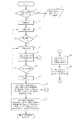
図1は、定電流−定電圧充電を行う最中に二次電池の内部情報検知する本発明の方法の一例をフローチャートにて示したものである。本発明の二次電池の内部情報検知方法を図1に従って説明する。なお、図1におけるS1〜S13のSは、ステップを表し、番号はステップ番号を表している。
【0049】
検知スタートとして、先ずステップ1で被検知電池が短絡しているかどうか判定し、短絡している場合には必要に応じて、被検知電池が短絡していることを警告する(ステップ2)。被検知電池が短絡していない場合は、ステップ3及び4の定電流充電を開始する。なお、ステップ1は、スキップしてもかまわない、ただし、その場合は、少なくとも定電圧充電中もしくは充電終了後に、被検知電池の短絡有無の判定ステップが必要であるのが一般的である。もっとも、予め短絡がないことが明らかになっている場合には、ステップ1は完全にスキップすることができる。ステップ5及び6で、電池電圧が所定の電圧に到達した時点で、定電圧充電に切り替わり、同時にステップ7で充電電流値と時間を計測開始する。ステップ8及び9において、充電終了条件を満たした時点で充電を終了する。ステップ8とステップ9の間もしくは、ステップ9とステップ10の間に、被検知電池の短絡有無の判定ステップを入れてもよい。次に、上記ステップ7における電流値と時間の計測から、ステップ12で定電圧充電モードでの充電電気量の算出、ステップ13で充電電流値が所定の値になった時間を記憶しておき、予め求めておいた正常な電池の充電電流値が所定の値になった時間と定電圧充電モードでの充電電気量と合わせて、ステップ10で、被検知電池が短絡していない場合に、前記式(1)から被検知電池の蓄電容量または正常な電池に対する蓄電容量比Dを求める。なお、ステップ12とステップ13の実行順序は逆にしてもよい。さらに、被検知電池の内部抵抗に関する情報を得たい場合には、ステップ10の結果と、予め求めておいた正常な電池の蓄電量Qに対する、開回路電圧の関係Voc(Q)及び内部抵抗の関係RI0(Q)と前記式(3)から、ステップ11で、被検知電池の内部抵抗値または正常な電池に対する内部抵抗の比率を求める。
【0050】
本発明の好適な実施の形態にかかる二次電池内部情報検知方法の最大の特徴は、図1のフローチャートのステップ7とステップ12とステップ13とステップ10にあり、すなわち定電流−定電圧充電を行い、定電流I0の充電から定電圧Vmaxの充電への切り替わり時から所定の電流値IMになるまでの時間tM'を計測し、定電圧Vmaxで充電される総電気量QCV'を計測もしくは算出し、予め求めておいた正常な電池の定電圧充電に移行時点から充電電流値がIMになるまでの時間tM、定電圧充電モードで充電される総蓄電量QCV及び正常な電池の蓄電容量(公称容量)と、関係式(1)から被検知電池の容量低下係数Dを算出する点にある。上記本発明の検知方法では、二次電池の定電圧充電領域の情報を用いることによって、被検知電池の充電前の蓄電量を考慮することなく、蓄電容量に関する情報を得ることが可能である。
【0051】
次に、図2を用いて、定電圧充電モードで充電電流値が所定の値になった時間と充電電気量(充電量)と式(1)から、被検知電池の蓄電容量または正常な電池に対する蓄電容量比を求められる理由を説明する。
【0052】
図2は、短絡も内部抵抗の増加も蓄電容量の低下もない正常な電池と、内部抵抗が増加しかつ蓄電容量が正常な電池のD倍に低下した被検知電池を、放電深度100%から、(一定の電流値I0で充電を開始し電池電圧が所定の電圧Vmaxに達した後、所定の電圧Vmaxで充電を充電終了まで行う、)定電流−定電圧充電方式によって充電した場合の、充電時間に対する充電電流をプロットしたものである。図2において、t0は、正常な電池における定電流充電から定電圧充電に移行する時点の充電開始からの時間で、Q0はt0までに蓄電された電気量である。これに対して、t0'は、内部抵抗が増加しかつ蓄電容量が低下した被検知電池における定電流充電から定電圧充電に移行する時点の充電開始からの時間で、Q0'はt0'までに蓄電された電気量である。さらに、内部抵抗が増加しかつ蓄電容量が低下した被検知電池の充電電流曲線を時間軸方向に1/D倍した充電電流曲線を内部抵抗のみ増大した電池の充電曲線とした場合、t0'/D(=t0'')は、内部抵抗が増加しかつ蓄電容量が正常な電池を同じである被検知電池における、定電流充電から定電圧充電に移行する時点の充電開始からの時間で、Q0'/D(=Q0'')はt0''までに蓄電された電気量である。ここで、正常な電池と内部抵抗のみが増大した電池の定電圧充電領域での充電電流曲線は、充電電流値IMで交差する。このとき、正常な電池、内部抵抗が増加しかつ蓄電容量が低下した被検知電池の、それぞれの定電流充電から定電圧充電に移行する時点から充電電流値がIMになるまでの時間をそれぞれtM、tM'とするとき、内部抵抗のみが増大した電池のそれはtM'/D(=tM'')になる。図2において、充電電流値がゼロになるまでの正常な電池と内部抵抗のみが増大した電池の蓄電量は等しいので、正常な電池の充電電流値がIMになる(時間=t0+tM)までの充電電気量と、内部抵抗のみ増大した電池の充電電流値がIMになるまでの充電量との差は、内部抵抗のみ増大した電池の充電電流値がIMからゼロになるまでの充電量と、正常な電池の充電電流値がIMからゼロになるまでの充電量との差に等しい。なお、充電量(充放電効率が100%の場合は:=蓄電量)は、充電電流を時間で積分した値である。さらに、正常な電池と内部抵抗が増加しかつ蓄電容量が低下した被検知電池と内部抵抗のみ増大した電池の、定電圧充電領域での充電電気量をそれぞれ、QCV、QCV'、QCV''とするとき、
I0×(t0−t0'/D)+QCV=QCV''で、(t0−t0'/D)=(tM'/D−tM)、QCV''=QCV'/Dであると考えてよいから、
I0×(tM'/D−tM)+QCV=QCV'/D
上記式から、
D=(QCV'−I0×tM')/(QCV−I0×tM) −−−−(1)
の関係が求まり、正常な電池の定電圧充電に移行時点から充電電流値がIMになるまでの時間tM、及び定電圧充電モードで充電される蓄電量QCV、蓄電容量(もしくは公称容量)のデータを保有しておき、被検知電池の定電圧充電に移行時点から充電電流値がIMになるまでの時間tM'、及び定電圧充電モードで充電される蓄電量QCV'を求めることによって、被検知電池が短絡していない場合には、上記式(1)から被検知電池の蓄電容量は算出される。前記所定の電流値IMは、0.5倍(IM=0.5×I0)であることが好ましい。誤差を考慮すると、前記定電流充電での充電電流I0の、0.4〜0.6倍(0.4×I0≦IM≦0.6×I0)の範囲であることが好ましい。もっとも、前述したように、電池の種類特有の「充電電流曲線の交点の電流値」IMを実験的に求めることは容易であるから、IMが特定の範囲に収まらない場合でも、本発明を適用することは可能である。加えて、充電電流曲線が厳密には一点で交差しない場合であっても、おおよその交点を近似的に定めることが可能な場合、かかる近似的に定められた交点の電流値をIMとみなすことによって本発明を適用することが可能である。
【0053】
また、前述の操作で、得られたtMとtM'の以下の関係から、
(i)(tM'−tM)>a>0の時、被検知電池の内部抵抗が正常な電池より増大している、
(ii)(tM−tM')>b>0の時、被検知電池の蓄電容量が正常な電池より低下している、
と判定することもできる(なお、a,bは電池の種類によって決まる定数である)。
【0054】
さらに、−b≦(tM'−tM)≦aの範囲にある場合、被検知電池は正常な電池の製品バラツキ範囲内で正常な電池の部類に分類することができる。
【0055】
また、前述の操作で、得られたQCVとQCV'の以下の関係から、
(iii)(QCV'−QCV)>c>0の時、被検知電池の内部抵抗が正常な電池より増大している、
(iv)(QCV−QCV')>d>0の時、被検知電池の蓄電容量が正常な電池より低下している、
と判定することも可能である(なお、c,dは電池の種類によって決まる定数である)。
【0056】
さらに、−d≦(QCV'−QCV)≦cの範囲にある場合、被検知電池は正常な電池の製品バラツキ範囲内で、正常な電池の部類に分類することができる。
【0057】
もっとも、厳密に言えば、被検知電池に内部抵抗の増大と蓄電容量の低下との両方が生じている場合、−b≦(tM'−tM)≦a、−d≦(QCV'−QCV)≦cのいずれかもしくは両方が満たされてしまう場合があり得る。かかる場合に、本来異常と判定されるべき被検知電池が正常な電池に分類されてしまうのを防ぐためには別途の考慮が必要となる。例えば、(3)式から得られるRI0'(Q0'')/RI0(Q0'')が所定値k以下であり、−b≦(tM'−tM)≦a、−d≦(QCV'−QCV)≦cの両方が満たされる場合に、被検知電池が正常であると判定することによって、より正確な判定が可能となる。
【0058】
被検知電池の短絡有無の判定
本発明の二次電池の内部情報検知方法で、被検知電池の蓄電電気量が求まるのは、短絡していないことが必要であるために、被検知電池の定電流−定電圧充電の定電圧充電モードに移行する前に、短絡していないことが確認されていることが好ましいが、定電圧充電後に短絡の有無の判定をしてもよい。なお、定電圧充電領域での充電電流値の時間変化ΔI/Δtの推移から、時間を無限大に外挿しても充電電流値がゼロにならず正の値を持つようであれば、被検知電池は短絡しており、正確な蓄電容量が求まらないことになる。
【0059】
被検知電池の充電も放電もしていない休止時、充電時、放電時、から選択される電池の状態を検知して短絡有無を判定でき、具体的には、休止時の電池の開回路電圧変化分、定電流充電モードにおける電池電圧の上昇率、定電圧充電モードにおける充電電流の降下率、放電時の電池電圧の降下率、から選択される一種類以上の電池の状態を検知して、短絡の有無の判定できる。
【0060】
すなわち、充電や放電を行っていない休止時では、経時時間に対する開回路電圧の低下がある場合に、短絡していると判定できる。
【0061】
定電流充電を行っている時には電池電圧もしくは開回路電圧の上昇が正常な電池に比べて小さい場合に、短絡していると判定できる。
【0062】
定電圧充電モードにおける充電電流の降下率が正常な電池より小さい場合、被検知電池は短絡している可能性があると判定できる。さらに、時間を無限に外そうすることで、内部抵抗増大か短絡か判定することができる。
【0063】
定電流放電時には電池電圧もしくは開回路電圧の下降が正常な電池に比べて大きい場合に、短絡していると判定できる。
【0064】
定電流−定電圧充電方式の定電流充電領域での短絡の有無の判定は、次のような方法にて判定することができる。被検知電池の放電深度が100%である時、充電開始から定電圧充電に切り替わるまでの時間が、正常な電池より多くかかる場合、被検知電池は短絡していると判定することができる。充電開始から定電圧充電に切り替わるまでの時間が、正常な電池より短い場合、被検知電池は内部抵抗が増大しているか、蓄電容量が低下しているか、内部抵抗が増大しかつ蓄電容量が低下していると判定することができる。
【0065】
また、被検知電池の放電深度がわからない場合、定電流I0の充電から定電圧Vmaxの充電への切り替わり時を基準に、それよりtcc時間前の(定電流充電モードでの)電池電圧Vccの時間当たりの上昇率ΔVcc/Δtに関して、被検知電池と正常な電池のそれを比較して、被検知電池の電圧の時間当たりの上昇率が、正常な電池のそれより小さいとき、被検知電池は、内部抵抗が低下しているか、短絡していると判定することができる。このとき、被検知電池の電圧の時間当たりの上昇率が、正常な電池のそれより大きい場合は、正常な電池より、被検知電池は、内部抵抗が増大しているか、蓄電容量が低下しているか、内部抵抗が増大しかつ蓄電容量が低下しているのいずれかであると判定することができる。
【0066】
さらに、被検知電池の短絡を判定するより簡便な方法としては、充電終了時直前の定電圧充電での充電電流値が、定電流充電での充電電流値の0.3倍以上あるとき、及びまたは、定電圧充電領域で充電電流の時間変化ΔI/Δtがプラスになる場合があるとき、被検知電池は短絡していると判定することもできる。また、定電流充電モードでの電池電圧の変化ΔV/Δtがマイナスになる場合があるときも、短絡していると判定することができる。
【0067】
充電終了条件
前記充電は、通常、定電圧充電モードで充電電流が所定の電流値Imin以下になった時点、もしくは充電開始から所定時間tfを経過した時点、のいずれかの時点で、終了する。ただし、短絡、異常発熱等の異常時の充電終了はこれに含まれない。
【0068】
定電圧充電モードでの充電量
前記(1)式に用いる定電圧充電領域での充電電気量QCV'は、充電を終了した時点までの総充電量、もしくは定電圧充電モードにおいて電流値がゼロに達する時点までの総充電電気量のいずれかである。被検知電池の蓄電容量は、定電圧充電モードの電流値がゼロに達する時点までの充電量から求めた方がより正確な値が求まる。ただし、定電流−定電圧充電方式で蓄電できる蓄電量は、充電を終了した時点までの充電量から求めた方がより正確な値が求まる。しかし、上記いずれの定電圧充電モードでの充電量を用いるかで、生じる被検知電池の算出蓄電容量の差は、大きくはない。
【0069】
内部抵抗に関する情報の検出
図1のステップ11を図2を参照しながら、次に説明する。
【0070】
二次電池の蓄電量と、開回路電圧、(電流が流れていないときの)静的内部抵抗には相関がある。また、定電流充電が行われている時の電池電圧と内部抵抗は、電池の蓄電量と電池の温度と、充電電流値に依存する。定電流放電が行われている時の電池電圧と内部抵抗もまた、電池の蓄電量と電池の温度と、放電電流値に依存する。
【0071】
そこで、先ず、正常な二次電池において、蓄電量Qに対する開回路電圧の関係Voc(Q)を求めておく。ついで、電池の充電温度T、定電流I0での充電モードにおける、蓄電量Qに対する内部抵抗の関係RI0(Q)を求めておく。また、電池の充電温度T、定電流I0での充電モードにおける、蓄電量Qに対する電池電圧の関係VI0(Q)を求めておいてもよい。さらに、上記、開回路電圧、並びに充電時の内部抵抗は、蓄電量Qに関する関数式Voc(Q)並びにRI0(Q)として求められているのがより好ましい。なお、上記正常な電池の蓄電量に対する開回路電圧Voc(Q)並びに内部抵抗のRI0(Q)は、正常な電池の予め計測されたデータ、もしくは正常な電池の予め計測されたデータから得られた関係式、コンピューターによるシミュレーションから得られた関係式、から選択されるものである。
【0072】
予め求めておいた、蓄電量Qに対する開回路電圧の関係Voc(Q)、内部抵抗の関係RI0(Q)から、蓄電量Q0''の正常な電池の開回路電圧と内部抵抗がそれぞれVoc(Q0'')とRI0(Q0'')であると求まる。
【0073】
一方、充電時の電池電圧Vcは開回路電圧Vocと充電電流値Icと電池の内部抵抗値Rcから次式のように表される。
【0074】
Vc=Voc+Ic×Rc、もしくはVoc=Vc−Ic×Rc。上記式において、定電流I0での充電モードにおける正常な電池の蓄電量がQ0''(なお、Q0''=Q0'/Dで、Q0'は、定電流I0の充電から定電圧Vmaxの充電への切り替わり時における被検知電池の蓄電量)であるとき、内部抵抗はRc=RI0(Q0'')、開回路電圧はVoc=Voc(Q0'')、充電電流はIc=I0で、電池電圧はVc=VI0(Q0'')、開回路電圧と充電電流と電池電圧と内部抵抗の関係はVoc(Q0'')=VI0(Q0'')−I0×RI0(Q0'')となる。図2において、内部抵抗のみ増大した電池の定電流I0の充電から定電圧Vmaxの充電への切り替わり時における蓄電量がQ0''、このときの内部抵抗をRI0'(Q0'')とすると、このときの開回路電圧は、Vmax−I0×RI0'(Q0'')と表せる。さらに、この内部抵抗のみ増大した電池の開回路電圧は、同じ蓄電量Q0''の正常な電池の開回路電圧と等しいので、
Voc(Q0'')=VI0(Q0'')−I0×RI0(Q0'')=Vmax−I0×RI0'(Q0'')と、表され、
この式の変形から、
RI0'(Q0'')={Vmax−Voc(Q0'')}/I0
さらに、次の(3)式、(3')式が得られる。
【0075】
RI0'(Q0'')/RI0(Q0'')={Vmax−Voc(Q0'')}/{I0×RI0(Q0'')} −−−−(3)
または、
RI0'(Q0'')/RI0(Q0'')={Vmax−VI0(Q0'')}/{I0×RI0(Q0'')}+1 −−−−(3')
ここで、図2から、
Q0''=Q0'/D=Q0−I0×(tM'/D − tM) −−−−(2)
なお、
D=(QCV'−I0×tM')/(QCV−I0×tM) −−−−(1)
である。Q0、tM、QCV、tM'、QCV'を計測して上記式(2)に代入することによって、通常は放電深度100%からの充電以外では求まらない被検知電池のQ0'を、放電深度100%未満からの充電時に求めることができる。
【0076】
予め、正常な電池の、定電流充電で充電される蓄電量(=充電電気量)Q0、定電圧充電モードで充電電流値がI0からIMになるまでの時間tM、定電圧充電モードにおける蓄電量(=充電電気量)QCV、蓄電量Qに関する関数式Voc(Q)、並びにRI0(Q)が求められており、被検知電池の定電圧充電モードでの充電電流値がI0からIMになるまでの時間tM'を計測し、定電圧充電モードにおける蓄電量(=充電電気量)QCV'を求めることによって、上記(1)式、(2)式、(3)式から、蓄電量Q0''での被検知電池の内部抵抗、蓄電量Q0''での正常な電池に対する被検知電池の内部抵抗の比率を求めることができる。なお、蓄電量Q0''での被検知電池の内部抵抗と蓄電量Q0'での被検知電池の内部抵抗と、の差は小さいと考えられるので、算出された蓄電量Q0''での被検知電池の内部抵抗を蓄電量Q0'での被検知電池の内部抵抗と推定することも可能である。さらに、蓄電量Q0''での正常な電池に対する被検知電池の内部抵抗の比率と、放電時の正常な電池に対する被検知電池の内部抵抗の比率との差は小さいと考えられるので、算出された蓄電量Q0''での正常な電池に対する被検知電池の内部抵抗の比率を放電時の正常な電池に対する被検知電池の内部抵抗の比率と推定することも可能である。
【0077】
機器の作動時間の算出
前記方法で、被検知電池の蓄電容量低下率Dを算出した後、正常な電池の蓄電容量CNと放電電流iと温度Tで決まる補正係数f(i,T)から、正常な電池の全放電量がCd=CN×f(i,T)と表されるとし、被検知電池を電源に使用している機器の平均消費電流をi、平均消費電力をp、被検知電池の平均電圧をVmとする時、機器の作動時間hを、次式h=(D×Cd)/i、もしくはh=(Vm×D×Cd)/pで算出することができる。前記放電電流iと温度Tで決まる補正係数f(i,T)には、正常な電池を用いて予め求められた計測データ、もしくは計測データを元に算出された関数式、またはコンピュータ・シミュレーションから得られたものを使用することができる。温度が低下すると電池の電解質のイオン伝導度が低下し、見かけ上の内部抵抗が増加するので、放電量が低下する。また、放電電流が高すぎると電池反応に寄与するイオンの供給が遅れ、見かけ上の内部抵抗が増加するので、放電量が低下する。したがって、これにより、被検知電池を機器に接続して使用する場合、機器の実際の作動時間も算出することが可能になる。前記放電電流iと温度Tで決まる補正係数f(i,T)を導入することで、放電できる電気量(残量)を高い精度で、予測することが可能になる。
【0078】
更に、正常な電池の内部抵抗RI0(Q0'')に対する被検知電池の内部抵抗RI0'(Q0')の比率RI0'(Q0'')/RI0(Q0'')を算出し、前記内部抵抗に関する情報RI0'(Q0'')/RI0(Q0'')から決定される補正係数rを用い、上記機器の作動時間hは、式h=(1/r)×(D×Cd)/i、もしくはh=(1/r)×(Vm×D×Cd)/pによって、より精度よく、算出される。
【0079】
〔二次電池の内部情報検知装置〕
本発明の二次電池の内部情報検知装置は、二次電池の定電流−定電圧充電において、少なくとも定電流−定電圧充電方式で充電する際の充電電流値Iを計測する手段と、定電流I0の充電から定電圧Vmaxの充電への切り替わり時からの時間tを計測する手段と、演算手段とを有し、被検知電池の内部情報を検知する、二次電池の内部情報検知装置である。前記演算手段は、前記計測された充電電流値I及びまたは定電圧充電の時間tの情報を用いて演算を行う。
【0080】
さらに、本発明の二次電池の内部情報検知装置は、記憶手段を有しているのが好ましく、この記憶手段は被検知電池と同種類で同型の正常な電池の特性の情報を記憶しているのが好ましい。予め記憶されている正常な電池の特性の情報と得られた被検知電池の計測情報とから、被検知電池の内部情報を得ることができる。
【0081】
被検知電池の蓄電容量を検知する本発明の検知装置は、少なくとも定電流−定電圧充電方式で充電する際の充電電流値Iを計測する手段と、定電流I0の充電から定電圧Vmaxの充電への切り替わり時からの時間tを計測する手段と、定電圧充電モードで充電電流値が所定値IMになったときの時間tM'を検知する手段と、定電圧充電モードでの充電量QCV'を検知する手段と、正常な電池の蓄電容量CN及び定電圧充電モードで充電電流値が所定値IMになるときの時間tMと定電圧充電モードでの充電量QCVの値を記憶した手段とを有し、かつ記憶されたこれらの正常な電池のCNとtMとQCVの値と被検知電池から検知されたtM'とQCV'の情報から被検知電池の蓄電容量を算出する演算手段を有する。蓄電容量の算出式は、前記式(1)を使用する。
【0082】
さらに、被検知電池の内部抵抗を検知する本発明の検知装置は、充電から定電圧Vmaxの充電への切り替わり時からの時間tを計測する手段と、定電圧充電モードで充電電流値が所定値IMになったときの時間tM'を検知する手段と、定電圧充電で充電され得る充電電気量QCV'を検知する手段と、正常な電池の蓄電容量CN及び定電圧充電モードで充電電流値が所定値IMになるときの時間tMと定電圧充電モードでの充電量QCVの値を記憶している手段と前記正常な電池の蓄電量Qに対する開回路電圧Voc(Q)の関係並びに正常な電池の定電流I0での充電モードでの蓄電量Qに対する内部抵抗RI0(Q)の関係をそれぞれ記憶している手段とを有し、前記被検知電池の計測情報と記憶されている正常な電池の特性情報から、被検知電池の蓄電容量と内部抵抗に関する内部情報を演算手段にて取得する。
【0083】
前記蓄電量Qに対する開回路電圧Voc(Q)並びに内部抵抗RI0(Q)の関係としては、データテーブル、関数式のいずれかを使用する。内部抵抗に関する内部情報を算出するために、前記式(1)、(2)、及び(3)を使用する。
【0084】
また本発明の二次電池の内部情報検知装置は、前記基礎データと前記検出手段から得られた情報を加工する演算手段を有していることが好ましい。前記演算手段が、被検知電池の蓄電容量、及び又は被検知電池の内部抵抗以外にも、充電終了までに要する時間を算出する手段、被検知電池を電源に使用している機器の作動時間を算出する手段、などを有していることも好ましい。
【0085】
さらに、本発明の二次電池内部情報検知装置には、前記計測手段から得られる情報、及び又は前記被検知電池の内部情報に関する情報を出力及び又は表示する手段を付随させてもよい。
【0086】
本発明の二次電池の内部情報検知装置の構成例
本発明の、二次電池の蓄電容量、内部抵抗で代表される内部情報の検知装置の主要部分の回路の構成の一例を図7に示す。基本的には、被検知電池を本装置と接続する端子(701)、被検知電池の端子間電圧を検出する電池電圧検出部(702)、被検知電池の充電電流を検出するところのセンス抵抗器(703)、増幅器(704)、及び制御部(705)から構成されている。
【0087】
ここで端子(701)は本発明を実施する被検知電池と本装置とを容易かつ確実に電気的に接続する事が可能である。電池電圧検出部(702)は、高い入力インピーダンスで被検知電池正負極間の端子間電圧を検出し、この電圧情報は制御部(705)に出力される。被検知電池の充電電流の検出は、センス抵抗器(703)により電流電圧変換されて電圧信号として増幅器(704)に入力し、この電圧情報は制御部(705)に出力される。制御部(705)は内部あるいは外部にタイマを有し、定電流から定電圧の充電への切り替わり時からの充電時間を計測し、定電流から定電圧の充電への切り替わり時からの充電時間に対する充電電流値のデータを取得する。更に制御部(705)は記憶手段として内部あるいは外部にメモリーを有しており、取得した被検知電池のデータを記憶する。また、上記メモリーは、被検知電池と同種類で同型の正常な電池の充電時間に対する充電電流値等の情報、及び取得された被検知電池のデータから内部情報を算出するための算出式をも記憶させておいてもよい。さらには、上記メモリーには、正常な電池の蓄電量Qに対する開回路電圧Voc(Q)、電池電圧VI0(Q)、内部抵抗RI0(Q)もあらかじめ入力されているのが好ましい。また、上記制御部(705)は、取得した被検知電池の定電圧充電時のデータから、被検知電池の蓄電容量や内部抵抗等に係わる内部情報を算出するための演算機能を有しているのが好ましい。
【0088】
本装置は、算出された被検知二次電池の蓄電容量等の情報を元に、さらに被検知電池の寿命判定、充電終了までの所要時間、あるいは機器の作動可能時間の情報表示機能を付加することも可能である。
【0089】
図7で説明した本発明の二次電池の内部情報検知装置の構成の一例は、単独の装置としても、被検知電池と接続し所定の動作を行うことができる。この時必要となる本装置電源は、図示していないが、外部から供給する以外にも、接続する被検知電池から、例えばレギュレータを介し、取り込むことも可能である。
【0090】
図8は、本装置を二次電池(801)と組み合わせ、電池パックに内蔵した一例を示す回路構成図である。電池パックのプラス端子(802)、マイナス端子(803)、充電用プラス端子(804)(充電用マイナス端子は前記マイナス端子を兼用)、電池電圧モニタ出力端子(805)、及び接続する機器との通信機能(806)を有している。必要に応じ、本装置制御部(705)に、電池パックに搭載する二次電池の過充電保護機能(807)や過放電保護機能(808)を行わせることもできる。なお、図8では二次電池1個から構成されている電池パックであるが、本発明による電池パックを構成する二次電池の個数はこれに限定されることなく、複数個であってもよい。
【0091】
上記通信機能(806)を有することにより、本発明の二次電池の内部情報検知装置を内蔵した電池パックは、二次電池あるいは電池パックの蓄電容量や寿命等の内部の情報、その情報から計算される充電終了までの所要時間あるいは機器の作動可能時間、を接続する機器に知らせることが可能となる。また、図7に代表される本装置を充電器に内蔵することもでき、これにより、電池の蓄電量、蓄電容量、満充電に要する残り時間、電池の劣化状態や寿命等の情報を表示するか、情報として外部に出力することができる。
【0092】
さらに図7に代表される本装置は、二次電池を使用する機器本体に内蔵することも可能である。また、図7に代表される本装置の機能を機器本体の制御部に持たせることもできる。すなわち、機器本体の制御部に、本発明の検知方法に基づくプログラムを入力し、本発明の検知機能を持たせることも可能である。例えば二次電池を接続して使用する携帯型パーソナルコンピュータでは、一般的に本体の動作を主に司る主制御部と、周辺機器とのやりとりを主に司る副制御部をそれぞれ有し、副制御部では、多くの場合、供給電源である二次電池からの電流及びまたは電圧の情報を監視している。上記監視情報を取得する機器の副制御部もしくは主制御部に、本発明の検知方法のプログラム及び必要な二次電池の基礎データを入力することで、本発明の検知装置の機能を機器本体に持たせて、二次電池の内部情報の検知を可能にし、機器の電源管理の精度を高めることができる。これにより、使用する二次電池の蓄電エネルギーを最大限に引き出し、機器の性能を最大限に発揮させることが可能になる。
【0093】
また、本発明の二次電池内部情報検知装置の記憶手段に、記憶する情報を必要に応じて、種類の異なる電池に対応する情報を入力しておくことによって、汎用性を持たせることが可能になる。その上で、本装置に適応する二次電池のタイプを選択する手段を設けることで可能となる。上記二次電池のタイプの選択手段としては、例えばスイッチ入力、有線もしくは無線の電気信号や光信号等での入力、を使用することができる。これにより、同一種類の二次電池であって型式が異なる場合や、二次電池の種類がリチウム(イオン)電池、ニッケル−水素電池、ニッケル−カドミウム電池、鉛蓄電池のように、異なる場合にも、対応することができる。
【0094】
被検知電池の内部情報検知プログラムを収めたメモリー媒体
本発明のメモリー媒体は、先に説明した、図1のフローチャートに代表される本発明の検知方法をプログラム化したプログラム、被検知電池と同種同型の正常な電池の基礎特性データを記憶したものである。充電機能を有し、かつメモリー媒体を接続して本発明の被検知電池の内部情報を検知する機能を有する、充電器や、ビデオカメラ、デジタルカメラ、携帯電話、携帯端末(Personal Digital Assistant)、電気自動車、に代表される二次電池を電源とする機器に、上記本発明のメモリー媒体を使用することができる。
【0095】
これにより、使用する二次電池の型式及び種類に変更が生じた場合でも、変更に対応する上記メモリー媒体を用意することで、容易に修正が可能になり、正確な二次電池内部情報の検知が可能になる。
【0096】
二次電池の内部情報検知装置の応用機器
前述してきたように、本発明の二次電池内部情報の検知方法は、劣化して蓄電容量の低下や内部抵抗の増加がもたらされた電池であっても、精度良く蓄電容量を算出することができるため、二次電池を電源として使用する機器においては、機器の作動時間を精度良く割り出すことができるし、寿命となった電池の交換時期を正確に知ることができる。そのため、本発明の二次電池の内部情報の検知方法を使用した二次電池の内部情報の検知装置を、二次電池を電源とする機器に搭載することで、機器と機器に搭載している二次電池の性能を最大限に引き出すことが可能になる。
【0097】
本発明の二次電池内部情報の検知装置を付加して性能が最大限引き出される機器の例としては、携帯電話、携帯端末、コンピューター、ビデオカメラ、デジタルカメラ、等の携帯機器、電気自動車やハイブリッド型自動車などの二次電池を電源とする乗り物、が挙げられる。さらに、本発明の二次電池の内部情報の検知装置を付加した、電池パック(単数個の二次電池がパッケージ化されたもの、または複数個の二次電池が直列もしくは並列に接合されてパッケージ化されたもの)や充電器も応用例として挙げられる。上記電池パックには二次電池の内部情報を機器とやりとりする通信機能を持たせても良い。
【0098】
本発明の二次電池内部情報の検知装置を付加して機能が高まる、上記例以外の装置やシステムとしては、製造した二次電池が良品であるか不要品であるか検査する二次電池の検査機器、電力貯蔵システム等も挙げられる。
【0099】
〔実験例〕
正常な電池に対する蓄電容量比率Dの妥当性
実験例1
正常な電池に対する蓄電容量比率Dで補正した充電電流曲線が、正常な電池の充電電流曲線と、定電流充電モードにおける電流値の1/2の電流値で交差することを実験にて示すことによって、本発明の電池の内部情報検知方法の妥当性を示した。
【0100】
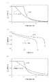
図6(1)は、サイズが直径17mm高さ67mmで公称容量が1300mAhの市販の正常なリチウムイオン二次電池と、正常な電池と同種同型の予め充放電を200回繰り返しサイクル劣化をさせた電池(被検知電池)にて、定電流−定電圧充電を行ったときの充電時間に対する充電電流値の関係をそれぞれ示した図である。なお定電流での充電電流値は1A、定電圧での充電電圧値は4.2Vとした。図6の(2)は、図6の(1)での定電流−定電圧充電後、電流密度による内部抵抗への影響が極力ない0.13Aの低電流で電池電圧が2.75Vに達するまで放電を行った場合の、放電量に対する電池電圧の関係を示した図である。
【0101】
図6の(2)より、0.13Aの低電流での放電では、予め充放電サイクルを200回繰り返した電池の放電量は、正常な電池の放電量の0.78倍であることがわかった。0.13Aの低電流での放電量は、蓄電容量であると見なせるので、予め充放電サイクルを200回繰り返した電池の正常な電池に対する蓄電容量比率Dは0.78であるといえる。
【0102】
図6の(1)の予め充放電サイクルを200回繰り返した電池の充電電流曲線を時間軸に1/0.78倍(=1.282倍)した充電電流曲線を、前記正常な電池の充電電流曲線とあわせて、図6の(3)に示した。図6の(3)から、200回充放電を繰り返して蓄電容量低下した電池の1/D倍して補正した充電電流曲線が、正常な電池の充電電流曲線と、定電流充電モードにおける充電電流値1Aのほぼ1/2の0.5Aの充電電流値のところで交差することがわかる。このことは、前記(1)式によって、正常な電池に対する被検知電池の蓄電容量比、もしくは被検知電池の蓄電容量が、求まることを示すものである。また、蓄電容量が低下し、内部抵抗が増大した、被検知電池の充電電流曲線を時間軸に1/D倍して補正することによって、内部抵抗のみが増大した電池の充電電流曲線が得られることも示すものである。
【0103】
二次電池特性の基礎データの取得例
実験例2
本発明の二次電池の内部抵抗に関する情報を検知するための、蓄電量に対する開回路電圧、定電流充電での蓄電量に対する内部抵抗の関係である関数式を得る手順の一例を図9〜11を参照して説明する。
【0104】
図9は、直径が17mm、高さが67mmのサイズで公称容量が1300mAhの、正常な市販のリチウムイオン二次電池において、定充電電流値が1A、上限電圧値が4.2Vの定電流−定電圧充電で満充電まで充電した後、休止時間を設け、0.26Aの電流で15分放電(本二次電池公称容量の約5%の電気量の放電)後、休止させるという間欠放電動作を、電池電圧が2.75Vに達するまで繰り返した場合の充放電特性を示す図であり、横軸は時間、縦軸は電池電圧である。
【0105】
図10は、図9で得られた積算放電量に対する電池電圧、及び放電休止時の電池電圧(=開回路電圧)の関係を示したものである。図10において、点線で示しているのは、間欠放電後の休止時の電池電圧(開回路電圧)をトレースしたもので、実線で示してあるのが放電時の電池電圧を示し、曲線の角の部分は放電を停止して休止に入った時点を表している。図10において、電池電圧が急激に低下し電池電圧が2.75Vに達したときの積算放電量が、二次電池の公称容量に等しい蓄電容量である。また、図10において、積算放電量がゼロの時点は、電池が満充電状態で、公称容量に等しい蓄電量を有している状態である。これらのことから、図10の点線の電圧曲線は、この電池の蓄電量と開回路電圧の関係を示したものである。なお、蓄電量は、蓄電容量(=放電終了までの積算放電量)から、その時点の積算放電量を減じた値である。
【0106】
ここで、蓄電量Qに対する開回路電圧Vocの関係の近似曲線の関数式Voc(Q)を一例として、以下のように蓄電量Qの関数として表すことができると仮定した。
Voc(Q)=Pn×Qn+Pn−1×Qn−1+Pn−2×Qn−2+・・・+P1×Q1 + P0×Q0
上記式で、PnからP0は、二次電池の種類、型式、公称容量等によって異なる定数である。
【0107】
本実験例では、開回路電圧Vocを蓄電量Qの6次の多項式と仮定し、サイズが直径17mm高さ67mmで公称容量が1300mAhの市販のリチウムイオン二次電池について、取得した基礎データを元に、図10の開回路電圧曲線のカーブフィッティングから、蓄電量Qに対する開回路電圧Vocの関数式を算出した。
【0108】
算出した蓄電量Qに対する開回路電圧Vocの関数式は以下の通りであった。
Voc(Q)=−5.1539×Q6+23.017×Q5−40.55×Q4+35.748×Q3−16.121×Q2+3.6098×Q+3.4299
図11は、図10にて求めた蓄電量Qに対する開回路電圧Vocの関係の近似曲線Voc(Q)と、定電流−定電圧方式で充電したときの充電量に対する電池電圧Vの関係をそれぞれ示した図である。充放電のクーロン効率は、ほぼ100%であるので、充電量=蓄電量となっている。今回使用したリチウムイオン電池の充放電のクーロン効率がほぼ100%であったので、充電量=蓄電量である。これにより、図10の放電量は〔満充電量−蓄電量Q〕となり、放電時の蓄電量Qと開回路電圧Vocの関係は、充電時の蓄電量Qと開回路電圧Vocの関係にも一致する。図11は、計測した、定電流1A−定電圧4.2V充電時の充電量(=蓄電量Q)と電池電圧の関係のグラフに、図10で得られた開回路電圧Voc(Q)の関係をプロットしたものである。なお、図11は、図10と同様の操作、すなわち定電流充電−定電圧充電において、ある一定時間充電後に充電を休止し開回路電圧を計測するという一連の操作を繰り返し、充電量に対する電池電圧と開回路電圧の関係を求めることによっても得られる。なお、上記測定データは、同種同型の電池であっても、個体差があるので、複数の電池から得られたデータを平均化したものを使用するのが好ましい。
【0109】
定電流充電領域での蓄電量と電池電圧の関係の関数式VI0(Q)についても、前述の関数式Voc(Q)と同様に蓄電量Qの6次の多項式と仮定し、図11から、直径17mm高さ67mmで公称容量が1300mAhの市販のリチウムイオン二次電池において求めた。図11の(直径17mm高さ67mmで公称容量が1300nAhの市販のリチウムイオン二次電池の)定電流充電量域での蓄電量Qに対する電池電圧曲線に一致するように6次多項式の定数項を求め、VI0(Q)を得た。求めた関数式は以下の通りである。
VI0(Q)=−61.579×Q6+198.46×Q5−248.74×Q4+153.06×Q3−47.891×Q2+7.3465×Q+3.5055
関数式RI0(Q)は、充電電流I0で充電を行う際に蓄電量がQ、電池電圧がVI0(Q)、開回路電圧がVoc(Q)、電池の内部抵抗がRI0(Q)であるとき、関係式RI0(Q)={VI0(Q)−Voc(Q)}/I0が成り立つので、蓄電量に対する内部抵抗の関係を表す関数式が算出される。算出した関数式は以下の通りである。
RI0(Q)=−56.4251×Q6+175.443×Q5−208.19×Q4+117.312×Q3−31.77×Q2+3.7367×Q+0.0756
なお、本例においては、Voc(Q)、VI0(Q)及びRI0(Q)の各関数式を、蓄電量Qの6次の多項式で表しているが、本発明においては、これらの多項式の次数に限定されるものではない。また、これらの関数式がn次の多項式に限定されるものでもない。
【0110】
短絡有無の判定
実験例3
本実施例では、本発明による被検知電池の短絡判定を行った。短絡した直径14mm高さ50mmのリチウムイオン二次電池を用い、定電流−定電圧充電方式で充電した場合の充電電流曲線、定電流−定電圧充電方式で充電した場合の電池電圧曲線、休止時の開回路電圧の経時変化、の3種類の計測結果を元に、同種同型の短絡していない正常な電池の計測データと比較して、本発明の電池内部情報検知方法の一つである、短絡の有無の判定の有効性を確認した。
【0111】
図12(1)は、定電流−定電圧充電における充電時間に対する充電電流の関係を、図12(2)に定電流−定電圧充電における充電時間に対する電池電圧の関係を、正常な電池と短絡している電池について示したものである。図12の(1)では、定電圧充電モードでの充電電流に着目すると、正常な電池では、時間とともに充電電流が低下して行き3時間でほぼ流れなくなしりゼロに収束しそうであるのに対して、短絡した電池では充電電流は正常な電池ほど減少せずゼロには収束しそうにないし、充電電流の時間変化ΔI/Δtがプラスになっている点も観測されている。
【0112】
図12の(2)では、正常な電池は定電圧充電モードに到達する時間が早いのに対して、短絡している電池は定電圧充電モードに達するまでの時間が長く、電池電圧の上昇が遅く、電池電圧の変化ΔV/Δtがマイナスになる点も観測されている。
【0113】
また、図12の(3)に充電を停止した後の、正常な電池と短絡している電池の開回路電圧の経時変化を示した。図12の(3)から、正常な電池では経時変化がほとんどないのに対して、短絡した電池では経時時間に対する開回路電圧の低下があることがわかる。
【0114】
以上の結果から、本発明の内部情報検知方法が、被検知電池の短絡有無の判定に有効であることが分かった。
【0115】
【実施例】
以下、実施例に基づき本発明を詳細に説明する。本発明はこれらの実施例に限定されるものではない。
【0116】
(実施例1)
本実施例では、充放電の繰り返しによって容量低下した電池の蓄電容量を本発明の方法で検知した後、実際の放電量から蓄電容量を求め、比較して、本発明の有効性を検証した。すなわち、図1のフローチャートに従って、ステップ10(S10)までの蓄電容量比を求めるところまで行い、その後、実際の放電量を測定した。
【0117】
先ず、サイズが直径17mm高さ67mmで公称容量が1300mAhの市販のリチウムイオン二次電池を2本用意した。用意した電池の中1本の開回路電圧の経時変化量を確認して短絡していないことを確認した。次に、この電池を1Aの一定の電流で電池電圧が4.2Vに達するまで充電し、電池電圧が4.2Vに達した後は、4.2Vの一定の電圧で、全充電時間が2.5時間になるまで充電し、4.2Vの定電圧充電に切り替わった時点から充電電流値が0.5Aになるまでの時間tMと定電圧4.2Vで充電される電気量QCVをそれぞれ計測した。なお、定電圧充電モードでの充電電流の時間変化からは、この電池が短絡していないことが確認された。
【0118】
ついで、0.13Aの定電流で、電池電圧が2.75Vまで、放電し、放電電気量を計測した。放電量は、公称容量値にほとんど一致し、1303.5mAhであった。従って、1303.5mAhの放電量がこの電池の蓄電容量である、正常な電池と見なすことができた。なお、充電電流値が0.5Aになるまでの時間tMは755秒で、定電圧4.2Vで充電された電気量QCVは339.9mAhであった。
【0119】
次に、別の1本の電池を用いて、1Aの一定の電流で電池電圧が4.2Vに達するまで充電し、電池電圧が4.2Vに達した後は、4.2Vの一定の電圧で、全充電時間が2.5時間になるまで充電する、定電流−定電圧充電後、0.65Aの定電流放電を電池電圧が2.75Vに達するまで行う、この充放電サイクルを200回繰り返し、蓄電容量検知用の被検知電池とした。
【0120】
被検知電池の開回路電圧の経時変化量を確認して短絡していないことを確認した。次に、200回の充放電を繰り返す前の電池の蓄電容量に対する、上記200回の充放電を繰り返した後の電池の蓄電容量比を算出するために、上記200回の充放電を繰り返した後の電池を、1Aの一定の電流で電池電圧が4.2Vに達するまで充電し、電池電圧が4.2Vに達した後は、4.2Vの一定の電圧で、全充電時間が2.5時間になるまで充電し、4.2Vの定電圧充電に切り替わった時点から充電電流値0.5Aになるまでの時間tM'と定電圧V4.2Vで充電される電気量QCV'をそれぞれ計測して、正常な電池に対する被検知電池の蓄電容量比Dを前述の(1)式から算出した。なお、充電電流値が0.5Aになるまでの時間tM'は2341秒で、定電圧4.2Vで充電された電気量QCVは754.9mAhであった。また、定電圧充電モードでの被検知電池の充電電流の時間変化からは、短絡していないことが確認された。
【0121】
その後、0.1C相当の0.13Aの定電流で、電池電圧が2.75Vまで放電し、放電量を計測し、この放電量を電池の蓄電容量とした。放電量は、1015.4mAhであった。
【0122】
得られた結果を表1にまとめた。
【0123】
なお、正常な電池の蓄電容量に対する被検知電池の蓄電容量の比Dは、次の式(1)で表される。
【0124】
D=(QCV'−I0×tM')/(QCV−I0×tM)−−−−(1)
(1)式において、I0=1A、tMは定電圧で充電された正常な電池の充電電流が1Aから0.5Aになるまでの時間、tM'は200回の充放電後の電池の充電電流が1Aから0.5Aになるまでの時間、QCVは定電圧で充電された先の正常な電池の電気量、QCV'は200回の充放電後の電池の定電圧で充電された電気量である。
【0125】
【表1】

表1の結果から、蓄電容量比の実測値と算出値の誤差は、次式で計算され、
|0.799−0.779|/0.779×100=2.5(%)
2.5%であった。また、算出されたD値から、被検知電池と同種同型の電池の公称容量がわかっていれば、被検知電池の蓄電容量も算出できることがわかる。
【0127】
本発明の手法を用いれば、定電流−定電圧充電の定電圧領域の充電電流の計測値から、蓄電容量が未知の電池の蓄電容量を放電することなく、簡便に、精度よく算出することができることがわかった。
【0128】
(実施例2)
本実施例では、充放電の繰り返しによって内部抵抗が増加し容量が低下した電池の、内部抵抗に関する情報を本発明の方法で検知し1Cの高電流での被検知電池の放電量を推定した後、実際の放電量と比較し、本発明の有効性を検証した。具体的には、正常な電池の基礎データを用い、被検知電池の定電流−定電圧充電時の定電圧充電モードにおける電流計測データから、内部抵抗に関する情報、実際の放電量を算出した。図1のフローチャートでは実施例1でのステップ10(S10)までの実行の後に、ステップ11(S11)を実行した。
【0129】
実施例1に引き続き、被検知電池を1C、すなわち1.3Aの高電流で放電する場合に、放電可能な電気量を推定した。
【0130】
放電量の推定は、以下の手順で行った。
【0131】
実施例1で得られた、定電流−定電圧充電時の定電圧モードにおける充電の充電電流が1Aから0.5Aになるまでの時間tM、tM'、定電圧充電モードでの充電量QCV、QCV'、正常な電池に対する被検知電池の蓄電容量比Dを、被検知電池の放電量の推算に用いた。
【0132】
また、正常な電池の、定電流I0の充電から定電圧Vmaxの充電への切り替わり時における蓄電量Q0は、次式〔定電流充電での蓄電量Q0〕=〔公称容量〕−〔定電圧での充電量QCV〕から求めた。なお、〔公称容量〕に替えて、満充電から定電流0.13Aでの電流で放電した全放電量を用いても計算できる。
【0133】
さらに、次式(2)から被検知電池の定電圧Vmaxの充電への切り替わり時における蓄電量Q0'を算出した。
【0134】
Q0'/D=Q0''=Q0−I0×(tM'/D−tM)−−−−(2)
(2)式において、tM'とtMは、それぞれ、被検知電池と正常な電池の充電電流が1Aから0.5Aになるまでの時間である。
【0135】
予め、上記正常な電池に関して、蓄電量Qに対する開回路電圧Vocの関係の近似曲線の関数式Voc(Q)、定電流充電領域での蓄電量と電池電圧の関係の関数式VI0(Q)を求めた。さらに、定電流1.3Aでの放電時の蓄電量Qに対する内部抵抗RId(Q)の関係をも求めた。
【0136】
さらに、前記(3)式によって、正常な電池に対する被検知電池の内部抵抗の比率γを算出した。
【0137】
γ=RI0'(Q0'')/RI0(Q0'')={Vmax−Voc(Q0'')}/{I0×RI0(Q0'')}−−−−(3)
上記式(3)において、Vmax=4.2V,I0=1Aである。
【0138】
定電流1.3Aでの放電時の正常な電池の電池電圧Vd(Q)は、先に得られている開回路電圧Voc(Q)と、放電時の内部抵抗RId(Q)に関する次式の、Vd(Q)=Voc(Q)−Id×RId(Q)で表される。ここで、Id=1.3Aで、電池電圧が急激に低下する2.75Vになった場合、2.75=Voc(Q)−1.3×RId(Q)となり、これより、このときの蓄電量Qが算出され、2.75Vまでの放電量は次の式で求まる。
【0139】
〔1.3Aでの放電量〕=〔公称容量〕−〔蓄電量Q〕
なお、〔公称容量〕は電池の定電流0.13Aでの全放電量で置き換えることができる。
【0140】
また、容量低下がない場合の被検知電池の電池電圧Vd'(Q)は、正常な電池の開回路電圧Voc(Q)と、放電時の被検知電池の内部抵抗RId'(Q)に関する次式、Vd'(Q)=Voc(Q)−Id×RId'(Q)で表される。ここで、算出した上記内部抵抗の比率γが、放電時も変わらないと仮定すると、RId'(Q)=γ×RId(Q)と表され、Vd'(Q)=Voc(Q)−Id×γ×RId(Q)
Id=1.3Aで、電池電圧が2.75Vになった場合、
2.75=Voc(Q')−1.3×γ×RId(Q')となり、これより、このときの蓄電量Q'が算出され、2.75Vまでの容量低下がない場合の被検知電池の放電量は次の式で求まる。
〔1.3Aでの非容量低下被検知電池の放電量〕=〔公称容量〕−〔蓄電量Q'〕
被検知電池は、実際には容量低下も伴うために、先に算出した通り、正常な電池の蓄電容量のD倍であり、被検知電池1.3Aでの放電量は、上で求めた〔1.3Aでの非容量低下被検知電池の放電量〕のD倍であると推定できる。ついで、被検知電池の実際の1.3Aでの放電量を計測し、推算放電量と比較した。得られた上記結果を表2にまとめて示した。
【0141】
表2から、充放電を200回繰り返して劣化した被検知電池の1Cでの実際の放電量と推算放電量との誤差は、次式にて算出され、
{|〔推算放電量〕−〔実際の放電量〕|/〔実際の放電量〕}×100(%){|945−919|/919}×100=2.8(%)
誤差は、2.8%であった。
【0142】
【表2】
これより、本発明の内部情報検知方法で、かなり精度よく、内部抵抗に関する情報が得られる。得られた内部抵抗に関する情報から放電量を推定することができることもわかった。
【0144】
また、内部抵抗に関する情報を上記方法とは別の、次のような方法にて求めることも可能である。正常な電池に直列抵抗をつないだ場合の定電圧充電曲線が前述の(7)式として既に求められている場合には、(7)式から被検知電池の内部抵抗が求められることになる。すなわち、実施例1で求められた被検知電池の、容量低下係数Dと定電流充電電流値の1/2に到達した時間tM'から、得られるtM'/D(=tM'')の値を(7)式の時間tに代入して求められる電流値が定電充電電流値の1/2すなわち0.5Aとなることから、正常な電池からの抵抗増加分である抵抗値rsが算出される。そこで、正常な電池の内部抵抗値R0が予め求められていたなら、被検知電池の内部抵抗値はR0+rsとなり、被検知電池の内部抵抗に関する情報が得られることになる。
【0145】
(実施例3)
本実施例では、高温雰囲気中で保存することによって劣化をさせた電池の蓄電容量を、本発明の電池の内部情報検知方法にて算出し、実測放電量と比較することで、本発明の有効性を確認した。
【0146】
実施例1で用いた同種同型の公称容量が1300mAhの市販のリチウムイオン二次電池を70℃の雰囲気中で1週間の高温保存を行ったサンプルを1本用意し、被検知電池とした。被検知電池の開回路電圧の経時変化から、被検知電池が短絡していないことを確認した。次に、この被検知電池を1Aの一定の電流で電池電圧が4.2Vに達するまで充電し、電池電圧が4.2Vに達した後は、4.2Vの一定の電圧で、全充電時間が2.5時間になるまで充電し、4.2Vの定電圧充電に切り替わった時点から充電電流値0.5Aになるまでの時間tMと定電圧V4.2Vで充電される電気量QCV'をそれぞれ計測した。
【0147】
ついで、実施例1の正常な電池の計測値を基準に、本発明の検知方法にて、正常な電池に対する被検知電池の蓄電容量の低下の割合を算出した。その後、被検知電池を0.13Aの定電流で、電池電圧が2.75Vまで放電し、放電量を計測し、この放電量を被検知電池の蓄電容量とした。
表3に得られた計測値及び算出値をまとめた。
【0148】
【表3】
表3の結果から、蓄電容量比の実測値と算出値の誤差は、次式で計算され、
|0.987−0.969|/0.987×100=1.8(%)
1.8%であった。また、算出されたD値から、被検知電池と同種同型の電池の公称容量がわかれば、被検知電池の蓄電容量も算出できる。
【0150】
本発明の手法を用いれば、蓄電容量が未知の電池の蓄電容量を放電することなく、定電流−定電圧充電の定電圧領域の充電電流の計測値から、簡便に、精度よく算出することができることがわかった。
【0151】
(実施例4)
本実施例では、実施例3で70℃の雰囲気中で1週間保存して準備した、サンプル電池を被検知電池として使用して、実施例2と同様な手順で、電池の内部抵抗に関する情報を取得し、1Cすなわち1.3Aでの定電流放電での放電量を推算した。また、得られた推算値を実測放電量と比較して、本発明の有効性を確認した。得られた、計測値及び算出値をまとめて、表4に示した。
【0152】
【表4】
表4から、70℃で一週間保存して劣化した被検知電池の1Cでの実際の放電量と推算放電量との誤差は、次式にて算出され、
{|〔推算放電量〕−〔実際の放電量〕|/〔実際の放電量〕}×100(%){|1246−1234|/1246}×100=1.0(%)
誤差は、1.0%であった。
【0154】
これより、本発明の内部情報検知方法で、かなり精度よく、内部抵抗に関する情報が得られ、また内部抵抗に関する情報から放電量を推定することができることがわかった。
【0155】
以上、実施例1から実施例4までの評価において、本発明の二次電池の内部情報検知方法を用いることによって、二次電池の蓄電容量及び内部抵抗に関する情報を極めて簡便な方法で取得できた。また、これにより、実際の放電量も高い精度で予測することができるとともに、電池の寿命に関しても判定をすることが可能であることがわかった。さらに、蓄電容量もしくは放電量の推算により、二次電池を電源にする機器の作動時間も精度良く検知することができることがわかる。なお、実施例1から実施例4までの評価において、一種類の市販のリチウムイオン二次電池を使用したが、二次電池のサイズや型式や種類に限定されることなく、定電流−定電圧充電方式を採用できる二次電池であれば、本発明は適用可能である。
【0156】
また、実施例1から実施例4まで、単セルの内部情報を検知する例を説明したが、これに限定されることなく、本発明を用いれば、複数のセルを並列、もしくは直列、または直並列に接続して形成されている電池パックにおいても、正常な基準となる電池パックから予め取得しておいたデータから、内部情報を得ることができる。
【0157】
【発明の効果】
以上説明してきたように、本発明によれば、定電流−定電圧充電方式での定電圧充電モードでの充電電流の計測から、簡便な方法にて、高精度の二次電池の内部情報を検知する方法が提供される。また、この電池の内部情報の検知により、二次電池を電源に使用した機器及び機械装置の電源制御が容易になるとともに、作動時間、充電のタイミング、電池の交換のタイミングなどを容易に知ることが可能になる。したがって、本発明の検知方法を用いた二次電池の内部情報の検知装置を電池パック、充電器、二次電池を電源とする機器または機械装置に付加することによって、二次電池の性能を最大限に引き出すことができ、機器または機械装置の性能も最大限に引き出すことができる。また、二次電池の出荷前に良品・不良品を検査する検査機器に、本発明の検知方法による二次電池の内部情報の検知装置を付加することで、精度の高い出荷検査を行うことも可能になる。
【図面の簡単な説明】
【図1】本発明における二次電池の内部情報検知手順を示したフローチャートの一例である。
【図2】本発明の検知方法に用いる算出式を説明するために、正常な電池、内部抵抗のみ増大した電池、及び内部抵抗増大かつ蓄電容量低下した電池、それぞれの定電流−定電圧充電モードにおける充電時間に対する充電電流の関係を示したグラフの一例である。
【図3】図の(1)は、正常な二次電池に抵抗器を並列に接続し、短絡を模した二次電池に充電器を接続した回路図である。図の(2)は、回路図(1)で並列接続の抵抗器の抵抗値を変化した場合の、定電流−定電圧充電モードにおける充電時間に対する充電電流と電池電圧の変化を示した一例である。
【図4】図の(1)は、正常な二次電池に抵抗器を直列に接続し、内部抵抗の増大を模した二次電池に充電器を接続した回路図である。図の(2)は、回路図(1)で直列接続の抵抗器の抵抗値を変化した場合の、定電流−定電圧充電モードにおけるの充電時間に対する充電電流の変化を示した一例である。図の(3)は、回路図(1)で直列接続の抵抗器の抵抗値を変化した場合の、定電流−定電圧充電モードにおける充電時間に対する充電電圧(=電池電圧)の変化を示した一例である。
【図5】図の(1)は、二次電池の定電流−定電圧充電において、定電圧充電モードに切り替わる直前からの充電電流の時間変化の実測値と、カーブフィッティングから求めた関数式による充電電流曲線との一致を示した図である。図の(2)は、直列接続抵抗器の抵抗値rs=0のときの正常な電池の関数式による充電電流曲線と、種々の直列接続抵抗器の抵抗値rsの関数式による充電電流曲線とが交差する電流値を抵抗値に対して示したものである。
【図6】図の(1)は、正常な二次電池とサイクル劣化した二次電池の定電流−定電圧方式での充電における、充電時間に対する充電電流の変化を示した図である。図の(2)は、図の(1)で充電した、正常な二次電池とサイクル劣化した二次電池を定電流で放電した場合の、放電量に対する電池電圧を示した図である。図の(3)は、図の(1)において、サイクル劣化した二次電池の蓄電容量の低下分を補正して、正常な電池と同じ蓄電容量にした場合の、充電電流曲線を示したものである。
【図7】本発明の二次電池の内部情報検知装置の一例の主構成部分を示す回路図である。
【図8】本発明の二次電池の内部情報検知装置を二次電池と組み合わせ、電池パックに内蔵した一例の主構成部分を示す回路図である。
【図9】二次電池を定電流−定電圧充電方式で充電した後に、放電と放電停止(休止)を繰り返したときの電池電圧の変化を示した図である。
【図10】図9で得られた積算放電量に対する、放電時の電池電圧及び放電休止時の電池電圧(開回路電圧)の関係を示したものである。
【図11】図10にて求めた蓄電量Qに対する開回路電圧の関係の近似曲線と、定電流一定電圧方式で充電したときの電池電圧の関係をそれぞれ示した例である。
【図12】図の(1)は、正常な二次電池と短絡した二次電池に対し、定電流−定電圧充電方式の充電を行ったときの充電時間に対する充電電流の関係を示した例である。図の(2)は、正常な二次電池と短絡した二次電池に対し、定電流−定電圧充電方式の充電を行ったときの充電時間に対する電池電圧の関係を示した例である。図の(3)は、正常な二次電池と短絡した二次電池に対し、定電流−定電圧充電方式の充電を行った後、充電も放電も行わない休止状態の経時時間に対する開回路電圧の関係を示した例である。[0001]
BACKGROUND OF THE INVENTION
The present invention relates to a storage capacity of a secondary battery, a method for detecting internal information represented by internal resistance, a detection device, a machine having the detection device, an internal information detection program, and a medium containing the program.
[0002]
[Prior art]
Advances in semiconductor devices and the development of small, lightweight, high-performance secondary batteries have led to rapid development of mobile devices such as portable personal computers, video cameras, digital cameras, mobile phones, and mobile terminals.
[0003]
Also, atmospheric CO2It is predicted that global warming will occur due to the greenhouse effect due to the increase in gas volume, and CO2There is a cry for reducing gas emissions. For this reason, CO2Thermal power plants that emit large amounts of gas are becoming more difficult to construct, and night power was installed in ordinary households as an effective use of power generated by power generators such as thermal power plants. So-called load leveling has been proposed in which a secondary battery is stored and used in the daytime when the amount of power consumption is high to level the load. In addition, electric vehicles that do not emit air pollutants, and hybrid electric vehicles that combine a secondary battery that suppresses air pollutant emissions and increases fuel efficiency with an internal combustion engine or fuel cell are being developed. Development of a high energy density secondary battery is expected as a secondary battery essential for these.
[0004]
For mobile devices, electric vehicles, and road conditioners that use the above-mentioned secondary battery, if internal information about the secondary battery used can be obtained, the operating time is managed by managing the power on the device side accordingly. Can be extended to the maximum, and if information on the lifetime of the secondary battery can be obtained, it is possible to know the replacement time of the battery and to avoid a sudden malfunction. For this reason, a technology for accurately detecting internal information represented by the storage capacity, the remaining amount of electricity, and the internal resistance of the secondary battery is extremely important.
[0005]
As one of methods for detecting the amount of remaining electricity, a method has been proposed in which battery voltage is measured and the remaining capacity is estimated and detected. Specifically, it is used in lithium ion secondary batteries that use a non-graphitizable carbon material for the negative electrode material, and the battery voltage gradually decreases with respect to the amount of discharged electricity (discharge amount), so the battery voltage is measured. Thus, the remaining amount of electricity (remaining capacity) is detected. However, in the method of calculating the remaining capacity from the battery voltage, it is difficult to accurately detect the remaining capacity because the battery voltage differs depending on the flowing current even if the remaining capacity is the same. Furthermore, it has been extremely difficult to detect the remaining capacity of a battery that has reached the end of its life and has deteriorated performance. Further, when the carbon material is a graphite-based carbon material, the battery voltage curve with respect to the discharge amount is flat, and it is not easy to apply the method of calculating the remaining capacity from the battery voltage.
[0006]
As another remaining capacity detection method, a method is also proposed in which the accumulated discharge electricity amount is stored and the remaining capacity is calculated by subtracting the accumulated discharge electricity amount from the charge electricity amount (charge amount). However, with this method, it is necessary to always memorize the current value and the discharge time, and when adding and charging in a charged state that does not lead to a complete discharge, the error becomes large, the battery has deteriorated in performance due to near life. It was not possible to detect the remaining capacity with high accuracy.
[0007]
Japanese Patent Laid-Open No. 4-2066 proposes a method for determining the capacity of a lead-acid battery based on the recovery characteristics of the battery voltage after pulse discharge, and Japanese Patent Laid-Open No. 4-136774 discloses a temporarily large current when the power is turned on. A method has been proposed in which the battery is discharged and the voltage drop is detected and compared with a preset battery voltage value. Further, in Japanese Patent Application Laid-Open No. 11-16607, a secondary battery is measured by measuring a battery voltage when a predetermined current is passed through a secondary battery for a predetermined time, and collated with a pre-recorded battery voltage-remaining capacity correspondence table. A method for detecting the remaining capacity of a battery has been proposed. However, it has been difficult to detect the remaining capacity of a battery in which any of the above proposals has deteriorated to increase the internal resistance or reduce the storage capacity.
[0008]
Next, Japanese Patent Application Laid-Open No. 9-134742 proposes a method for determining deterioration by measuring the internal impedance immediately before the end-of-discharge voltage by supplying an alternating current to the storage battery with an impedance measuring instrument. Therefore, since a measuring instrument for measuring impedance is required, the measuring device becomes large, and measurement cannot be performed while the secondary battery is used, which is not practical.
[0009]
Further, Japanese Patent Application Laid-Open No. 11-271408 discloses that a secondary battery is charged with a constant current and a constant voltage (charging is started at a constant current value and the battery voltage reaches a predetermined voltage, and then charging is completed at a predetermined voltage. In the case of charging by the method), a method for estimating the degree of deterioration of the detected battery from the charge amount in the constant current charge mode, the current drop amount or the current change amount in the constant voltage charge mode has been proposed. . However, in the above detection method, from the measured charge amount in the constant current charge mode, current drop amount or current change amount in the constant voltage charge mode, it is possible to uniquely calculate the internal information of the battery regarding the storage capacity. Has not reached. In addition, the above detection method correlates with the storage capacity of the battery at the time of deterioration, the charge amount in the constant current charge mode, the current drop amount in the constant voltage charge mode, and the current change amount in the constant voltage charge mode. It is shown that there is the most correlation between which relationships, and how reliable the storage capacity of the battery is detected, specifically how the storage capacity is detected. Not. Furthermore, it is determined whether the detected battery is short-circuited and the capacity is reduced, whether the battery is deteriorated and the internal resistance is increased and the capacity is reduced, or whether the storage capacity itself is reduced. It is not possible to grasp the detailed deterioration status. Information on whether or not the battery is short-circuited is important in order to use the battery more safely and to accurately grasp the internal information of the battery.
[0010]
In a secondary battery, repeated charge and discharge causes an increase in internal resistance and a decrease in storage capacity due to deterioration of the electrode active material, dropping or peeling of the electrode active material from the current collector, decomposition of the electrolyte, etc. There is a case. Furthermore, if the connection portion of the lead connecting the electrode and the output terminal is peeled off for some reason such as vibration, the internal resistance of the battery may increase. In addition, there is a case where a short circuit occurs between the positive electrode and the negative electrode due to metal deposition due to an electrochemical reaction, and the internal resistance and the storage capacity are both lowered. When detecting internal information of a battery with respect to an increase in internal resistance, a decrease in storage capacity, or a short-circuited battery, a large error has occurred in the conventional method.
[0011]
Therefore, it can be used for various types of secondary batteries, and can be used for batteries whose performance has deteriorated due to reduced storage capacity or increased internal resistance. There is a strong desire for a method and apparatus for achieving this. Furthermore, development of a method and apparatus for detecting battery life, that is, performance degradation, is also expected.
[0012]
[Problems to be solved by the invention]
The present invention solves the problem of low detection accuracy in the internal information detection method of a secondary battery represented by the above-mentioned conventional storage capacity, and a method and apparatus for detecting internal information of the secondary battery with high accuracy, and It is to provide various devices and machines that apply the.
[0013]
[Means for Solving the Problems]
The present inventors have made a secondary battery using a constant current-constant voltage charging method (charging is started at a constant current value and charging is performed at a predetermined voltage after the battery voltage reaches a predetermined voltage until the end of charging). In a secondary battery in which only the internal resistance is increased, the charging current curve in the constant voltage charging region has a certain charging current value I regardless of the increase in the internal resistance.MAnd found that it intersects the charging current curve of a normal battery. Thereby, if the secondary battery is not short-circuited, a current value I with a charging current in the constant voltage charging mode is obtained.MIt has also been found that the information on the storage capacity of the secondary battery can be obtained from the measurement of the time until it becomes and the presence or absence of a short circuit can be determined from the convergence value of the charging current in the constant voltage mode. Furthermore, it has also been found that information on the internal resistance of the battery can be obtained from the determination of the storage capacity. Unless otherwise specified, the “constant voltage charging mode” in this specification represents a state of charging at a constant voltage or a case of charging at a constant voltage from the control or computer program side. From the battery side, this is synonymous with “a state of being charged at a constant voltage” or “a case of being charged at a constant voltage”. Conversely, the “constant current charging mode” means a state or a case where charging is performed with a constant current.
[0014]
In the present invention, when charging is performed by the constant current-constant voltage charging method, at least (A) the time t from the time when the detected battery shifts from the constant current charging mode to the constant voltage charging mode and the constant voltage charging mode. Measuring the charging current value I;
(B) The charging current I in the constant voltage charging mode from the time of transition to constant voltage charging is a predetermined current value IMThe step of finding the time until
(C) a step of obtaining a charge electricity amount (charge amount) in the constant voltage charge mode;
(D) a step of referring to a charging current characteristic in a constant voltage charging mode of a normal battery of the same type and type as the detected battery;
Made ofWhether or not the detected battery is short-circuited, the storage capacity of the detected battery (amount of electricity that can be stored), the internal resistance of the detected battery, the charge amount of the detected battery, and the amount of electricity that can be used by the detected battery (remaining amount) Or any combination of these information is detected.This is an internal information detection method. The internal information obtained by the above method includes the presence / absence of a short circuit of the detected battery, the storage capacity of the detected battery (the amount of electricity that can be stored), the internal resistance of the detected battery, the charge amount of the detected battery, The amount of electricity that can be used (remaining amount), or any combination of information. According to the internal information detection method of the secondary battery of the present invention, even if the depth of discharge before the start of charging is unknown, that is, even when charging is performed in addition to the battery with the remaining amount of electricity. Internal information represented by the storage capacity of the battery to be detected can be obtained.
[0015]
Further, the present invention provides an apparatus for detecting internal information of a secondary battery,
Means for measuring a charging current value I when charging the secondary battery to be detected by at least a constant current-constant voltage charging method, and a constant current I0From the charging mode to constant voltage VmaxMeans for measuring the time t from the time of switching to the charging mode,The charging current value in the constant voltage charging mode is a predetermined value I M Time t when M Means to detect 'and the amount of electricity Q in constant voltage charging CV Means for detecting 'and the storage capacity C of a normal battery N And the charging current value in the constant voltage charging mode is a predetermined value I M Time t M And charge amount Q in constant voltage charging mode CV Means for storing the value of and stored C of these normal batteries N And t M And Q CV Value and t detected from the detected battery M 'And Q CV It has calculation means to calculate the storage capacity of the battery to be detected from the information 'This is an internal information detection device for a secondary battery.
Further, the present invention provides an apparatus for detecting internal information of a secondary battery,
Means for measuring a charging current value I when charging a secondary battery to be detected by at least a constant current-constant voltage charging method, and a charging current value in a constant voltage charging mode is a predetermined value I M Time t when M Means for detecting 'and the amount of charge Q that can be charged by constant voltage charging CV Means for detecting 'and the storage capacity C of a normal battery N And the charging current value in the constant voltage charging mode is a predetermined value I M Time t M And the amount of electricity Q when charging at constant voltage CV And the open circuit voltage V with respect to the storage amount Q of the normal battery oc Relation of (Q) and constant current I of normal battery 0 Internal resistance R with respect to charge amount Q during charging at I0 Means for storing the relationship of (Q),
Internal information of the secondary battery, wherein internal information on the storage capacity and internal resistance of the detected battery is acquired by the calculation means from the measurement information of the detected battery and the stored characteristic information of the normal battery It is a detection device.
[0016]
Furthermore, the present invention is a battery pack comprising one or more secondary batteries to which the internal information detection device is added.
[0017]
The present invention also includes a machine (preferably an inspection device for inspecting whether a manufactured secondary battery is a non-defective product or a defective product, a charge for charging the secondary battery, comprising the internal information detection device. Or a portable device such as a mobile phone, a mobile terminal, or a portable computer, or a machine selected from a mobile body such as an automobile, a bicycle, a ship, an aircraft, and a spacecraft).
[0018]
Furthermore, the present invention is a program for detecting internal information of a secondary battery, wherein the detection method is incorporated in a program for detecting internal information of the secondary battery. The present invention is also a storage medium storing such a program.
[0019]
In the detection method of the present invention, whether or not the detected battery is short-circuited indicates that the detected battery is short-circuited when the charging current value takes a positive value when the charging time in the constant voltage charging mode is extrapolated infinitely. If the charging current value converges to zero, it can be determined that the detected battery is not short-circuited. However, in constant current-constant voltage charging, there is a case where the degree of short circuit is large so as not to enter the constant voltage charging mode. In this case, the above short circuit determination cannot be applied.
[0020]
In addition,In the charging current characteristic in the constant voltage charging mode of the normal battery in the step (D), the relational expression obtained from the premeasured data of the normal battery or the premeasured data of the normal battery, Properties selected from data or relations obtained from computer simulations can be used.
[0021]
The above results were revealed by the following series of simulation experiments.
[0022]
First, when the secondary battery is short-circuited, how the charging characteristics change is connected to the secondary battery in parallel, and a constant current-constant voltage charging operation is performed. The transition of charging current was observed. FIG. 3 (1) shows a resistor r connected to a normal secondary battery having an internal resistance R and having no short circuit (a portion surrounded by a broken line).PIt is the circuit diagram which connected these in parallel and connected to the charging device. Resistor rPCorresponds to a short-circuit portion of the secondary battery, and the charging current I from the charging devicec= Ib+ IrCurrent flows into the battery when current flowsbFlows through the resistor r in the short circuitPHas a current IrWill flow. Here, the internal resistance R ′ of the pseudo short-circuit battery in which the resistors are connected in parallel is R to R and rPParallel combined resistance value R ′ = R × rP/ (R + rP). (2) of FIG. 3 uses a commercially available lithium ion secondary battery having a diameter of 17 mm and a height of 67 mm and a nominal capacity of 1300 mAh as the secondary battery in FIG.PIf the resistor is not connected, the resistance value is 22Ω, 10Ω resistor rPIt is the figure which showed the battery voltage (V) and the charging current (A) with respect to the charging time in each constant current (1A) -constant voltage (4.2V) charge mode at the time of connecting. The horizontal axis represents time, the left vertical axis represents the charging current value, and the right vertical axis represents the battery voltage. From the charging current curve in the constant voltage charging mode of (2) in FIG. 3, when the resistor is not connected to the battery, that is, when the resistor is not short-circuited, the charging current is obtained by extrapolating the charging time infinitely. If we see zero and the resistor is connected to the battery, i.e. short-circuited, the charging current does not go to zero and has a positive value even when extrapolating the charging time indefinitely I understood it. More specifically, in FIG. 3 (1), the charging proceeds, and the open circuit voltage of the charged secondary battery (the part surrounded by the broken line part) is the charging voltage V for constant voltage charging.maxAfter reaching the value, the charging current stops flowing through the battery, ie, Ib= 0. On the other hand, resistor rPHas a constant current Ir= Vmax/ RPContinues to flow. That is, Ic= Ib+ Ir= Vmax/ RPThe open circuit voltage of the battery is the charge voltage VmaxThe charging current value I output from the charging device even after reachingcDoes not converge to 0, and is considered to have a constant current value.
[0023]
Furthermore, the present inventors have found that in the case of a secondary battery in which the storage capacity is not reduced and only the internal resistance is increased, a resistor r is connected in series with the secondary battery in order to know how the charging characteristics change.SWas connected to increase the internal resistance, charge operation was performed, and the transition of the charge current in the constant voltage charge mode was observed. (1) in FIG. 4 shows that a resistor r is connected to a normal secondary battery having an internal resistance R and having no short circuit (a portion surrounded by a broken line).sIt is the circuit diagram which connected to in series and was connected to the charging device. Resistor rsCorresponds to an increase in internal resistance of the secondary battery. 4 (1), a commercially available lithium ion secondary battery having a diameter of 17 mm and a height of 67 mm and a nominal capacity of 1300 mAh is used as the secondary battery.sWhen the resistor is not connected, the resistor r has a resistance value of 55 mΩ, 89 mΩ, 110 mΩ, and 150 mΩ.sFIG. 4 is a diagram showing the charging current (A) with respect to the charging time [min] in the constant voltage charging mode of 1 A (ampere) -4.2 V (volt) when each is connected. FIG. 4 (3) shows the charging voltage (V) in (2). From the charging current curve in (2) of FIG. 4, regardless of the resistance value of the resistor connected to the battery, a current value with a charging current curve in the constant voltage charging mode (hereinafter, this current value is referred to as “charging current”). In some cases, the current value at the intersection of the curves is 0.5 A, which is half of the current value of constant current charging. .4 times to 0.6 times may be considered). Further, as the resistance value connected in series increases, the rate of change (decrease) in the charging current value with respect to the charging time at a constant voltage decreases. Even if a battery with a resistor connected in series and the internal resistance value increased in a simulated manner, if the charging time is extrapolated indefinitely, the charging current converges to zero, and the amount of charge at this time is connected to the resistor. It will be the same as the normal battery charge. That is, the charge amount of the battery charged until the charging current becomes zero is the same for a normal battery and a battery in which only the internal resistance is increased. In addition, from (3) of FIG. 4, as the resistance value connected in series increases, the time to reach a predetermined voltage, that is, the charging time with a constant current is shortened, and is determined at an early stage after the start of charging. It turns out that it transfers to charge of a voltage.
[0024]
Further, in order to obtain the position of the intersection of the charging current curve in detail, the function expression of the charging current curve is obtained based on the data at the time of charging in (2) of FIG. 4, and the resistance value of the resistor connected in series is obtained. Regardless of whether the charging current curves intersect at almost the same point, that is, whether the charging time until reaching a certain charging current value is the same, and where the current value when intersecting was calculated.
[0025]
Since it is difficult to obtain a functional expression of a curve of the charging current with respect to the charging time at a time, first, a functional expression to be fitted is obtained from the shape of the curve of the charge amount Q (t) with respect to the charging time t and an actual measurement value, and then the charging time. Taking the difference between the time-differentiated charge amount function and the measured current value, and then formulating the current difference curve as a functional equation, finally the charging time of the secondary battery connected with the series resistance The function equation of the charging current curve was obtained.
[0026]
Specifically, a function expression of a curve of the charge amount with respect to the charge time of the secondary battery in which the series resistance was connected stepwise was obtained by the following procedure.
[0027]
First of all, the relationship between the charge amount and the charging time in the constant voltage charging mode in constant current-constant voltage charging is expressed by the following relational expression (4).
Q (t) = C1× [1-exp {-C2× (t-C0)}] + C3 ---- (4)
(C1C2= 1)
It can be expressed as follows. Various resistors are connected in series to a normal battery, and experimental data of the amount of charge with respect to the charging time when performing constant current-constant voltage charging is obtained, curve fitting is performed, and the relational expression (4 C) in0, C1, C2, C3And the resistance value connected in series. Here, exp {} indicates the {@} power of the base e of the natural logarithm.
[0028]
Next, since the current value is given by the time derivative dQ / dt of the electric quantity Q, both sides of the relational expression (4) are time-differentiated and the following relational expression (5)
IA(T) = exp {-C2× (t-C0)} ---- (5)
Got.
[0029]
Next, the actual measurement data of the charging current value with respect to the charging time is compared with the relational expression (5). From the shape of the curve of the difference ΔI (t), the difference ΔI (t) is expressed by the following relational expression (6).
ΔI (t) = C5× {(t-C0) / C4}C6Xexp [1-{(t-C0) / C4}C6] ---- (6)
C in relational expression (6)4, C5, C6And the resistance value connected in series.
[0030]
C obtained above0, C1, C2, C3, C4, C5, C6The relationship between the charging current value with respect to the charging time is expressed by the following relational expression (7)
I (t) = IA(T) + ΔI (t)
= Exp {-C2× (t-C0)} + C5× {(t-C0) / C4}C6Xexp [1-{(t-C0) / C4}C6] ---- (7)
As a formula.
[0031]
Various resistors are connected in series to a commercially available lithium-ion secondary battery with a diameter of 17 mm, a height of 67 mm, and a nominal capacity of 1300 mAh, and charging is performed using a constant current-constant voltage charging method with a battery in which only the internal resistance is increased. As a result of measuring the charging characteristics at the time of charging and formulating the charging current curve with respect to the internal resistance value and the charging time by the above procedure, C in the relational expression (7)0, C2, C4, C5, C6Is the resistance value rsCan be expressed as the following functional expressions.
[0032]
C0= 2715.17 × exp (−0.0110319 × rs)
C2= 0.000525602 × exp (−0.0046066 × rs)
C4= 20.8542 × rs
C5= 0.163965
C6= 0.234332 × {exp (0.00937306 × rs) -1} +1
In FIG. 5 (1), regarding the relationship of the charging current value with respect to the charging time of the secondary battery in which the resistor is connected in series, the measured data is indicated by a white circle, and the data calculated from the above obtained formula is indicated by a solid line. It was. From FIG. 5 (1), it can be seen that a mathematical formula relating to the charging current is obtained which agrees very well with the measured data from immediately before switching to the constant voltage charging mode. In FIG. 5 (1), the straight line portion where the current value is constant in the constant current charging mode is not correctly reflected in the charging curve (solid line) yet, that is, the portion where the current value is constant (period of constant current charging mode) ) Needs to be corrected.
[0033]
Therefore, the correction for the period of the constant current charging mode was performed according to the following procedure.
[0034]
When charging with a constant current-constant voltage method is performed until the charging current value becomes 0, a normal battery and a battery in which a resistor is connected in series to a normal battery should have the same total charged amount. Therefore, the amount of charge until the charge current value of a normal battery becomes 0, that is, the integrated value of the obtained charge current according to the time of the equation (7) is changed to the resistance value r.sResistance value r so that the integrated value until the charging current value in Equation (7) of the battery to which the battery is connected becomes zero is equal.sThe shift amount (time) on the time axis for correcting the equation (7) of the battery connected to the normal battery, that is, the normal battery and the resistance value rsThe difference of the start time of the constant voltage charge mode with the battery connected to was calculated. Next, a resistance value r obtained by correcting the shift amount (time).sThe equation (7) of the battery connected to the battery is obtained, the equation (7) of the charging current of the normal battery and the corrected resistance value rsThe current value at which the current value of the mathematical formula (7) of the battery connected to is equal was obtained. FIG. 5 (2) shows the current value at which the charging current curve of a normal battery not connected to the resistor and the charging current curve of the battery connected to the resistor intersect when the resistance value of the resistor connected in series is changed. Is plotted against the resistance value. Here, regardless of the resistance value of the resistors connected in series, the crossing at 0.5 A, which is approximately a half of the current value 1 A in the constant current charging mode, is the charging in the constant voltage charging mode expressed as a formula. It was also confirmed from the current curve.
[0035]
In a secondary battery with no capacity reduction, regardless of an increase in internal resistance, the amount of power stored when charging with the constant current-constant voltage charging method until the charging current becomes substantially zero is the same. In addition, assuming a battery in which only the storage capacity is D times that of a normal battery (D is a constant 0 <D ≦ 1), the charging current with respect to the charging time during charging in the constant current-constant voltage charging method It is clear from the experiments of the present inventors that the charging current curve in which the values are plotted almost coincides with a curve obtained by multiplying the charging current curve of a normal battery by D in the time axis direction. From the above discovery by the present inventors, in a battery in which the internal resistance is increased and the storage capacity is D times lower than that of a normal battery, the charging current value with respect to the charging time at the time of charging in the constant current-constant voltage charging method The curve obtained by multiplying the charging current curve plotted by 1 / D in the time axis direction intersects with the charging current curve of the normal battery constant voltage charging mode at a certain charging current value, and from the charging current curve multiplied by 1 / D The amount of electricity stored is equal to that of a normal battery. From these relationships, the reduction rate D of the storage capacity is obtained.
[0036]
The most important feature of the internal information detection method of the detected battery according to the present invention is that the storage capacity of the detected battery that is not short-circuited (the amount of electricity that can be stored) is D times the normal storage capacity of the battery (D is a constant 0). <D ≦ 1) (assuming that the storage capacity does not decrease when D = 1), the constant current I in the detected battery0From constant charge to constant voltage VmaxCurrent value I from the time of switching to chargingMThe time untilM', Constant voltage VmaxQ is the total amount of electricity chargedCV'And for normal batteries, tM, QCVWhen the following relational expression (1)
D = (QCV'-I0XtM') / (QCV-I0XtM) ---- (1)
Therefore, the storage capacity of the battery to be detected is detected as being D times the storage capacity of a normal battery. Accordingly, when the storage capacity C of a normal battery is used, it is possible to calculate that the storage capacity C ′ of the detected battery is C × D. When the value of D is equal to or less than a certain value, it can be determined that the lifetime is reached.
[0037]
The predetermined current value IMIs the charging current value in the constant current charging I0Is 0.4 × I0≦ IM≦ 0.6 × I0Is preferred, IM= 0.5 × I0It is more preferable that
[0038]
Furthermore, the detection method of the present invention provides a constant current I in a detected battery whose storage capacity is D times the storage capacity of a normal battery.0From constant charge to constant voltage VmaxThe amount of electricity stored at the time of switching to charging is Q0', Constant voltage VmaxCurrent value I from the time of switching to chargingMThe time untilM'With normal batteries, Q0, TMWhen the following relational expression (2)
Q0'' = Q0-I0X (tM'/ DtM---- (2)
Q required from0'' (Q0'' = Q0'/ D),
Normal battery charge amount Q, open circuit voltage relationship Voc (Q) and constant current I0Relation of internal resistance in charge mode RI0From (Q), storage amount Q0The normal circuit open circuit voltage and internal resistance at '' are Voc (Q0'') And RI0(Q0''), The detected battery is charged0The internal resistance when '' is RI0'(Q0''), The following relational expression (3)
RI0'(Q0'') / RI0(Q0'') = {Vmax-Voc (Q0'')} / {I0× RI0(Q0'')} ---- (3)
To detect internal information related to the internal resistance of the battery to be detected. Note that the open circuit voltage Voc (Q) and the internal resistance R with respect to the charged amount of the normal battery.I0(Q) is selected from pre-measured data of normal batteries, relational expressions obtained from pre-measured data of normal batteries, or relational expressions obtained from computer simulations. The above function RI0(Q) is the charging current I0The internal resistance of the battery in the charging mode atI0(Q), the battery voltage is VI0(Q), relational expression R when the open circuit voltage of the battery is Voc (Q)I0(Q) = {VI0(Q) -Voc (Q)} / I0Is calculated from
[0039]
On the other hand, the increase in the internal resistance of the battery to be detected with respect to a normal battery can also be obtained using the above-described equation (7). That is, the current curve of the charging current value in the constant voltage charging mode is multiplied by 1 / D in the time axis direction (meaning correction for the storage capacity), and the resistance value r that matches equation (7)sThe increase in resistance can be obtained.
[0040]
In the detection method of the present invention, after detecting that the storage capacity of the detected battery is D times the storage capacity of the normal battery, the storage capacity C of the normal battery is detected.NAnd the correction coefficient f (i, T) determined by the discharge current i and the temperature T, the total discharge amount of a normal battery is Cd= CNXf (i, T), when the average current consumption of the device using the detected battery as a power source is i, the average power consumption is p, and the average voltage of the detected battery is Vm, Is expressed by the following formula h = (D × Cd) / I or h = (Vm × D × Cd) / P. Further, an expression h = (1 / r) × (D × C) using a correction coefficient r determined from information on the increase in internal resistance.d) / I or h = (1 / r) × (Vm × D × Cd) / P, the operating time of the device can be calculated more accurately. The correction coefficient f (i, T) determined by the discharge current i and the temperature T can be obtained from measurement data obtained in advance using a normal battery, a function equation calculated based on the measurement data, or a computer simulation. The one obtained can be used.
[0041]
The secondary battery to which the internal information detection method of the secondary battery of the present invention can be applied is a secondary battery that is charged by a constant current-constant voltage charging method, and a preferable example of the applicable secondary battery is lithium. A lithium secondary battery using an oxidation-reduction reaction (in this specification, “lithium secondary battery” is a concept including a so-called “lithium ion secondary battery”), but is limited to a lithium secondary battery. It is not a thing.
[0042]
Moreover, this invention is a secondary battery internal information detection program which applied the internal information detection method of the said secondary battery of the said invention.
[0043]
Furthermore, the present invention provides means for measuring a charging current value I in at least a constant current-constant voltage charging mode, to which the internal information detection method for a secondary battery of the present invention is applied, and a constant current I0From constant charge to constant voltage VmaxThe internal information detection of the secondary battery having means for measuring the time t from the time of switching to the charging of, the calculation means, and the storage means, and applying the internal information detection method of the secondary battery of the present invention The apparatus includes a battery pack including one or more secondary battery units, a secondary battery charger, a machine / device using the secondary battery as a power source, and a secondary battery inspection apparatus.
[0044]
In the battery pack of the present invention, by transmitting the internal information of the secondary battery to the device to which the battery pack is connected, it is possible to maximize the performance of the device or machine, and avoid a sudden operation stop. Is possible. With the charger of the present invention, it is possible to grasp the performance deterioration of the secondary battery during charging. The secondary battery inspection apparatus of the present invention can easily detect non-defective products and defective products if applied before shipment. In a device using a secondary battery as a power source, the present invention can detect the amount of electricity (remaining amount) that can actually be used with high accuracy, thereby facilitating power management and extending the operating time. it can.
[0045]
In addition, the present inventors further experimented whether it is generally appropriate that the charging current curve in the constant voltage charging mode substantially intersects at a certain point. As a result, it was confirmed that in many lithium ion batteries, they substantially intersect at 1/2 of the current value of constant current charging. Therefore, it is generally considered that a value of 1/2 of the current value of constant current charging is reasonable. However, considering a certain amount of measurement error, it is possible to consider the “current value at the intersection of the charging current curve” with a range of 0.4 to 0.6 times the current value of constant current charging. is there. Furthermore, since it is possible to easily obtain the “current value at the intersection of the charging current curve” specific to the type of battery by the experiment as described above, even if the “current value at the intersection of the charging current curve” of the battery is determined. "" Is a value far from 1/2, it is possible to apply the present invention described in detail below. In addition, even if the charging current curves do not strictly intersect at one point, the present invention described in detail below can be applied as long as an approximate intersection can be determined approximately. In that case, “predetermined current value I in the claims of the present application”M"Is the current value of the intersection point determined approximately.
[0046]
DETAILED DESCRIPTION OF THE INVENTION
In a preferred embodiment of the present invention,
"In constant current-constant voltage charging,
1. If the charging time is sufficiently long so that the charging current approaches zero, the full charge amount of the battery in which only the internal resistance has increased is equal to the full charge amount of a normal battery. (The storage capacity of the battery (= full charge amount) is the amount of electricity charged from a discharge depth of 100% to full charge, and is equal to the area surrounded by the charging current curve and the charging time axis. Therefore, only the internal resistance increases. In the case of the battery, the area surrounded by the charging current curve and the charging time axis is equal to that of a normal battery.)
2. The charging current curve of the battery in which only the internal resistance has increased intersects with the charging current curve of a normal battery in the constant voltage charging mode at the current value of a constant value (for example, 1/2) of the current value in the constant voltage charging mode. .
3. The charge current curve of a battery that has deteriorated to D times the normal battery storage capacity (the amount of electricity that can be stored) and increased internal resistance is 1 / D times in the time axis direction. It becomes a charging current curve. (In a battery having a storage capacity D times that of a normal battery, the area surrounded by the charging current curve and the charging time axis is D times that of a normal battery. This means that the storage capacity is normal. When the area surrounded by the charging current curve and the charging time axis of the battery which has become D times the battery is multiplied by 1 / D, it is equal to that of the normal battery and the battery in which only the internal resistance is increased. That is, in a battery whose storage capacity is D times that of a normal battery, if the charge current curve is multiplied by 1 / D in the charge time axis direction, it can be converted into a charge current curve in which only the internal resistance is increased.
Using this point, the capacity of the deteriorated battery is calculated.
[0047]
Hereinafter, the internal information detection method of the secondary battery of this invention is demonstrated concretely using FIG.
[0048]
FIG. 1 is a flowchart showing an example of the method of the present invention for detecting internal information of a secondary battery during constant current-constant voltage charging. A method for detecting internal information of a secondary battery according to the present invention will be described with reference to FIG. Note that S in S1 to S13 in FIG. 1 represents a step, and the number represents a step number.
[0049]
As a detection start, it is first determined in
[0050]
The greatest feature of the secondary battery internal information detection method according to the preferred embodiment of the present invention is in Step 7,
[0051]
Next, referring to FIG. 2, from the time when the charging current value becomes a predetermined value in the constant voltage charging mode, the amount of charge electricity (charge amount), and the equation (1), the storage capacity of the detected battery or the normal battery The reason why the storage capacity ratio with respect to can be obtained will be described.
[0052]
FIG. 2 shows a normal battery without a short circuit, an increase in internal resistance, and a decrease in storage capacity, and a detected battery with an increase in internal resistance and a storage capacity that is D times lower than that of a normal battery from a discharge depth of 100%. , (Constant current value I0The battery voltage is set to the predetermined voltage VmaxAfter reaching the predetermined voltage VmaxThe charging current is plotted with respect to the charging time when charging is performed by the constant current-constant voltage charging method. In FIG. 2, t0Is the time from the start of charging at the time of transition from constant current charging to constant voltage charging in a normal battery, Q0Is t0This is the amount of electricity stored up to this point. In contrast, t0'Is the time from the start of charging at the time of transition from constant current charging to constant voltage charging in the detected battery with increased internal resistance and reduced storage capacity,0'T0It is the amount of electricity stored up to '. Further, when the charging current curve obtained by multiplying the charging current curve of the detected battery whose internal resistance is increased and the storage capacity is reduced by 1 / D in the time axis direction is the charging curve of the battery whose internal resistance is increased, t0'/ D (= t0'') Is the time from the start of charging at the time of transition from constant-current charging to constant-voltage charging in a detected battery having the same internal resistance and a normal storage capacity.0'/ D (= Q0'') T0It is the amount of electricity stored until ''. Here, the charging current curve in the constant voltage charging region of the normal battery and the battery in which only the internal resistance is increased is the charging current value IMCross at. At this time, the charge current value of the normal battery and the detected battery whose internal resistance increased and the storage capacity decreased decreased from the respective constant current charging to constant voltage charging.MEach time untilM, TM'Is that of a battery with only increased internal resistance, tM'/ D (= tM'')become. In FIG. 2, since the charged amount of a normal battery until the charging current value becomes zero is equal to that of a battery in which only the internal resistance is increased, the charging current value of the normal battery is IM(Time = t0+ TM) And the charging current value of the battery whose internal resistance only increased is IMThe difference between the amount of charge and the amount of charge until the battery charge current value of the battery increased only by the internal resistance is IMThe amount of charge from zero to zero and the normal battery charge current value are IMIs equal to the difference from the amount of charge to zero. The charge amount (when the charge / discharge efficiency is 100%: = amount of stored electricity) is a value obtained by integrating the charge current with time. Furthermore, the amount of charge in the constant voltage charging region of the detected battery whose normal resistance is increased and the internal resistance is increased and the storage capacity is decreased and the battery whose only internal resistance is increased are respectively expressed as QCV, QCV', QCV''
I0X (t0-T0'/ D) + QCV= QCV'', (T0-T0'/ D) = (tM'/ DtM), QCV'' = QCV'/ D
I0X (tM'/ DtM+ QCV= QCV'/ D
From the above formula:
D = (QCV'-I0XtM') / (QCV-I0XtM) ---- (1)
The charging current value is I from the time of transition to normal battery constant voltage charging.MTime tMAnd charge amount Q charged in constant voltage charging modeCV, The storage capacity (or nominal capacity) data is stored, and the charging current value is IMTime tM'And the amount of charge Q charged in the constant voltage charging modeCVBy obtaining ', when the detected battery is not short-circuited, the storage capacity of the detected battery is calculated from the above equation (1). The predetermined current value IMIs 0.5 times (IM= 0.5 × I0) Is preferable. Considering the error, the charging current I in the constant current charging00.4 to 0.6 times (0.4 × I0≦ IM≦ 0.6 × I0) Is preferable. However, as described above, the “current value at the intersection of the charging current curve” I specific to the type of battery.MIs easy to determine experimentally, so IMEven if is not within a specific range, the present invention can be applied. In addition, even when the charging current curves do not strictly intersect at a single point, if it is possible to approximately determine an approximate intersection, the current value at the approximately determined intersection is IMTherefore, the present invention can be applied.
[0053]
In addition, t obtained by the above-described operationMAnd tMFrom the following relationship,
(I) (tM'-TM)> A> 0, the internal resistance of the detected battery is higher than that of a normal battery.
(Ii) (tM-TMWhen ')> b> 0, the storage capacity of the detected battery is lower than that of a normal battery.
(A and b are constants determined by the type of battery).
[0054]
Furthermore, −b ≦ (tM'-TM) In the range of ≦ a, the detected battery can be classified into a normal battery category within the range of normal battery product variation.
[0055]
In addition, the Q obtained by the above operationCVAnd QCVFrom the following relationship,
(Iii) (QCV'-QCV)> C> 0, the internal resistance of the detected battery is higher than that of a normal battery.
(Iv) (QCV-QCVWhen ')> d> 0, the storage capacity of the detected battery is lower than that of a normal battery.
(C and d are constants determined by the type of battery).
[0056]
Furthermore, −d ≦ (QCV'-QCV) In the range of ≦ c, the detected battery can be classified as a normal battery within the range of normal battery product variation.
[0057]
Strictly speaking, however, if the detected battery has both an increase in internal resistance and a decrease in the storage capacity, −b ≦ (tM'-TM) ≦ a, −d ≦ (QCV'-QCV) ≦ c, or both of them may be satisfied. In such a case, in order to prevent a detected battery that should be determined to be abnormal originally from being classified as a normal battery, additional consideration is required. For example, R obtained from equation (3)I0'(Q0'') / RI0(Q0″) Is less than or equal to the predetermined value k, and −b ≦ (tM'-TM) ≦ a, −d ≦ (QCV'-QCV) ≦ c When both of the conditions are satisfied, it can be determined more accurately by determining that the battery to be detected is normal.
[0058]
Judgment of presence or absence of short circuit of battery to be detected
In the method for detecting internal information of the secondary battery of the present invention, the amount of electricity stored in the battery to be detected needs to be not short-circuited. Therefore, the constant current-constant voltage charging constant voltage of the battery to be detected Although it is preferable that it is confirmed that there is no short circuit before shifting to the charging mode, the presence or absence of a short circuit may be determined after constant voltage charging. If the charging current value does not become zero even if extrapolated to infinite time from the transition of the time change ΔI / Δt of the charging current value in the constant voltage charging region, it will be detected. The battery is short-circuited and an accurate storage capacity cannot be obtained.
[0059]
It can detect the state of the battery selected from resting, charging, or discharging when the battery to be detected is neither charged nor discharged, specifically, the open circuit voltage change of the battery during rest Detects the state of one or more types of batteries selected from the following: battery voltage rise rate in constant current charge mode, charge current drop rate in constant voltage charge mode, battery voltage drop rate during discharge The presence or absence of can be determined.
[0060]
That is, it can be determined that a short circuit occurs when there is a decrease in the open circuit voltage with respect to the elapsed time during a pause when charging or discharging is not performed.
[0061]
When constant current charging is performed, it can be determined that a short circuit occurs if the rise in battery voltage or open circuit voltage is small compared to a normal battery.
[0062]
When the rate of decrease in charging current in the constant voltage charging mode is smaller than that of a normal battery, it can be determined that the detected battery may be short-circuited. Furthermore, by increasing the time indefinitely, it is possible to determine whether the internal resistance has increased or a short circuit has occurred.
[0063]
When the battery voltage or the open circuit voltage drop is larger than that of a normal battery during constant current discharge, it can be determined that a short circuit has occurred.
[0064]
The determination of the presence or absence of a short circuit in the constant current charging region of the constant current-constant voltage charging method can be performed by the following method. When the discharge depth of the battery to be detected is 100%, it can be determined that the battery to be detected is short-circuited when it takes more time than the normal battery to start switching to constant voltage charging. When the time from the start of charging to switching to constant voltage charging is shorter than that of a normal battery, the detected battery has an increased internal resistance, decreased storage capacity, increased internal resistance, and decreased storage capacity Can be determined.
[0065]
If the discharge depth of the battery to be detected is not known, the constant current I0From constant charge to constant voltage VmaxBased on the time of switching to charging, tccBattery voltage V before time (in constant current charging mode)ccRate of increase ΔV per hourccAs for / Δt, when the rate of increase of the voltage of the detected battery per time is smaller than that of the normal battery when the detected battery is compared with that of the normal battery, the internal resistance of the detected battery decreases. Or it can be determined that it is short-circuited. At this time, if the rate of increase in the voltage of the detected battery per time is larger than that of the normal battery, the detected battery has an increased internal resistance or a lower storage capacity than the normal battery. It can be determined that the internal resistance has increased and the storage capacity has decreased.
[0066]
Furthermore, as a simpler method for determining a short circuit of the battery to be detected, when the charging current value at constant voltage charging immediately before the end of charging is 0.3 times or more of the charging current value at constant current charging, and Alternatively, when the time change ΔI / Δt of the charging current may be positive in the constant voltage charging region, it can be determined that the detected battery is short-circuited. In addition, when the battery voltage change ΔV / Δt in the constant current charging mode may be negative, it can be determined that a short circuit has occurred.
[0067]
Charge termination conditions
The charging is usually performed in a constant voltage charging mode where the charging current is a predetermined current value I.minAt the time whenfEnd at any point in time after elapse of. However, this does not include the end of charging in the event of an abnormality such as a short circuit or abnormal heat generation.
[0068]
Charge amount in constant voltage charging mode
Charging quantity Q in constant voltage charging region used in equation (1)CV'Is either the total charge amount until the end of charging or the total charge amount until the current value reaches zero in the constant voltage charging mode. A more accurate value can be obtained as the storage capacity of the battery to be detected from the amount of charge until the current value in the constant voltage charging mode reaches zero. However, a more accurate value can be obtained for the amount of power that can be stored by the constant current-constant voltage charging method from the amount of charge until the point of time when charging is completed. However, the difference in the calculated storage capacity of the detected battery is not large depending on the charge amount in any one of the constant voltage charging modes.
[0069]
Detecting information about internal resistance
Next,
[0070]
There is a correlation between the amount of charge stored in the secondary battery, the open circuit voltage, and the static internal resistance (when no current is flowing). Further, the battery voltage and the internal resistance when the constant current charging is performed depend on the charged amount of the battery, the temperature of the battery, and the charging current value. The battery voltage and internal resistance when the constant current discharge is performed also depend on the battery charge amount, the battery temperature, and the discharge current value.
[0071]
Therefore, first, a relationship Voc (Q) of the open circuit voltage with respect to the charged amount Q in a normal secondary battery is obtained. Next, battery charging temperature T, constant current I0Of the internal resistance with respect to the charged amount Q in the charging mode atI0Find (Q). Also, the battery charging temperature T, constant current I0Of battery voltage to amount of charge Q in charging mode atI0(Q) may be obtained in advance. Further, the open circuit voltage and the internal resistance at the time of charging are expressed by a functional expression Voc (Q) and RI0More preferably, it is required as (Q). Note that the open circuit voltage Voc (Q) and the internal resistance R with respect to the charged amount of the normal battery.I0(Q) is selected from pre-measured data of normal batteries, relational expressions obtained from pre-measured data of normal batteries, or relational expressions obtained from computer simulations.
[0072]
The relationship Voc (Q) of the open circuit voltage with respect to the charged amount Q and the relationship R of the internal resistance, which are obtained in advance.I0From (Q), storage amount Q0'' Normal battery open circuit voltage and internal resistance are Voc (Q0'') And RI0(Q0'').
[0073]
On the other hand, the battery voltage V during chargingcIs the open circuit voltage Voc and the charging current value IcAnd battery internal resistance RcFrom the following equation.
[0074]
Vc= Voc + Ic× RcOr Voc = Vc-Ic× Rc. In the above formula, constant current I0The normal battery charge amount in the charge mode is Q0'' (Q0'' = Q0'/ D, Q0'Is the constant current I0From constant charge to constant voltage Vmax), The internal resistance is Rc= RI0(Q0''), The open circuit voltage is Voc = Voc (Q0''), Charging current is Ic= I0The battery voltage is Vc= VI0(Q0''), The relationship between open circuit voltage, charging current, battery voltage and internal resistance is Voc (Q0'') = VI0(Q0'') -I0× RI0(Q0''). In FIG. 2, the constant current I of the battery in which only the internal resistance is increased.0From constant charge to constant voltage VmaxThe amount of electricity stored at the time of switching to charging is Q0'', The internal resistance at this time is RI0'(Q0''), The open circuit voltage at this time is Vmax-I0× RI0'(Q0''). Furthermore, the open circuit voltage of the battery in which only the internal resistance is increased is equal to the charged amount Q.0'' Because it is equal to the normal open circuit voltage of the battery
Voc (Q0'') = VI0(Q0'') -I0× RI0(Q0'') = Vmax-I0× RI0'(Q0'')
From the transformation of this formula,
RI0'(Q0'') = {Vmax-Voc (Q0'')} / I0
Further, the following equations (3) and (3 ′) are obtained.
[0075]
RI0'(Q0'') / RI0(Q0'') = {Vmax-Voc (Q0'')} / {I0× RI0(Q0'')} ---- (3)
Or
RI0'(Q0'') / RI0(Q0'') = {Vmax-VI0(Q0'')} / {I0× RI0(Q0'')} + 1 ----- (3 ')
Here, from FIG.
Q0'' = Q0'/ D = Q0-I0X (tM'/ D-tM---- (2)
In addition,
D = (QCV'-I0XtM') / (QCV-I0XtM) ---- (1)
It is. Q0, TM, QCV, TM', QCVBy measuring 'and substituting it into the above equation (2), the Q of the battery to be detected, which is normally not obtained except for charging from a discharge depth of 100%0'Can be obtained when charging from less than 100% discharge depth.
[0076]
Charge amount (= charged electricity amount) Q of a normal battery charged by constant current charging in advance0In the constant voltage charging mode, the charging current value is I0To IMTime tM, Amount of charge in constant voltage charge mode (= charge amount of electricity) QCV, A functional expression Voc (Q) related to the storage amount Q, and RI0(Q) is required, and the charging current value in the constant voltage charging mode of the detected battery is I0To IMTime tM'And measure the amount of electricity stored in constant voltage charging mode (= amount of charge) QCVBy obtaining ', from the above formulas (1), (2), and (3), the charged amount Q0'' The internal resistance of the battery to be detected0The ratio of the internal resistance of the detected battery to the normal battery can be obtained. Storage amount Q0'' The internal resistance of the battery to be detected and the charged amount Q0The difference between the detected battery and the internal resistance of the detected battery is considered to be small.0'' Is the internal resistance of the battery to be detected0It is also possible to estimate the internal resistance of the battery to be detected. Furthermore, the amount of electricity stored Q0The difference between the ratio of the internal resistance of the detected battery to the normal battery and the ratio of the internal resistance of the detected battery to the normal battery at the time of discharging is considered to be small.0It is also possible to estimate the ratio of the internal resistance of the detected battery to the normal battery at '' as the ratio of the internal resistance of the detected battery to the normal battery during discharge.
[0077]
Calculation of equipment operating time
After calculating the storage capacity decrease rate D of the detected battery by the above method, the storage capacity C of the normal batteryNAnd the correction coefficient f (i, T) determined by the discharge current i and the temperature T, the total discharge amount of a normal battery is Cd= CNXf (i, T), when the average current consumption of the device using the detected battery as a power source is i, the average power consumption is p, and the average voltage of the detected battery is Vm, Is expressed by the following formula h = (D × Cd) / I or h = (Vm × D × Cd) / P. The correction coefficient f (i, T) determined by the discharge current i and the temperature T can be obtained from measurement data obtained in advance using a normal battery, a function equation calculated based on the measurement data, or a computer simulation. The one obtained can be used. When the temperature is lowered, the ionic conductivity of the battery electrolyte is lowered and the apparent internal resistance is increased, so that the discharge amount is lowered. On the other hand, if the discharge current is too high, the supply of ions that contribute to the battery reaction is delayed, and the apparent internal resistance increases, so the amount of discharge decreases. Therefore, this makes it possible to calculate the actual operating time of the device when the battery to be detected is connected to the device. By introducing a correction coefficient f (i, T) determined by the discharge current i and the temperature T, it is possible to predict the amount of electricity (remaining amount) that can be discharged with high accuracy.
[0078]
Furthermore, the internal resistance R of a normal batteryI0(Q0'') The internal resistance R of the detected batteryI0'(Q0') Ratio RI0'(Q0'') / RI0(Q0'') To calculate information R about the internal resistanceI0'(Q0'') / RI0(Q0)), The operating time h of the device is given by the equation h = (1 / r) × (D × Cd) / I or h = (1 / r) × (Vm × D × Cd) / P to calculate with higher accuracy.
[0079]
[Internal information detection device for secondary battery]
The internal information detection device for a secondary battery according to the present invention includes a means for measuring a charging current value I when charging at least with a constant current-constant voltage charging method in constant current-constant voltage charging of a secondary battery, and a constant current I0From constant charge to constant voltage VmaxThis is a secondary battery internal information detection device that has means for measuring time t from the time of switching to charging and a calculation means, and detects internal information of the battery to be detected. The calculation means performs calculation using information on the measured charging current value I and / or constant voltage charging time t.
[0080]
Further, the internal information detection device for a secondary battery of the present invention preferably has a storage means, which stores information on the characteristics of normal batteries of the same type and the same type as the detected battery. It is preferable. The internal information of the detected battery can be obtained from the information on the characteristics of the normal battery stored in advance and the obtained measurement information of the detected battery.
[0081]
The detection device of the present invention for detecting the storage capacity of a battery to be detected includes at least means for measuring a charging current value I when charging by a constant current-constant voltage charging method, and a constant current I.0From constant charge to constant voltage VmaxMeans for measuring the time t from the time of switching to charging, and the charging current value in the constant voltage charging mode is a predetermined value IMTime t whenMMeans to detect 'and charge amount Q in constant voltage charging modeCVMeans for detecting 'and the storage capacity C of a normal batteryNIn the constant voltage charging mode, the charging current value is a predetermined value IMTime tMAnd charge amount Q in constant voltage charging modeCVMeans for storing the values of and stored C of these normal batteriesNAnd tMAnd QCVValue and t detected from the detected batteryM'And QCVAnd calculating means for calculating the storage capacity of the detected battery from the information '. The formula (1) is used as a formula for calculating the storage capacity.
[0082]
Furthermore, the detection device of the present invention for detecting the internal resistance of the battery to be detected is a constant voltage V from charging.maxMeans for measuring the time t from the time of switching to charging, and the charging current value in the constant voltage charging mode is a predetermined value IMTime t whenMMeans for detecting 'and the amount of charge Q that can be charged by constant voltage chargingCVMeans for detecting 'and the storage capacity C of a normal batteryNIn the constant voltage charging mode, the charging current value is a predetermined value IMTime tMAnd charge amount Q in constant voltage charging modeCVThe relationship between the means for storing the value of open circuit voltage Voc (Q) with respect to the charged amount Q of the normal battery and the constant current I of the normal battery0Internal resistance R with respect to charge amount Q in charge modeI0(Q) each storing means, and from the measurement information of the detected battery and the stored characteristic information of the normal battery, internal information on the storage capacity and internal resistance of the detected battery is obtained. Obtained by calculation means.
[0083]
The open circuit voltage Voc (Q) and the internal resistance R with respect to the charged amount QI0As the relationship (Q), either a data table or a function expression is used. In order to calculate internal information about internal resistance, the above equations (1), (2), and (3) are used.
[0084]
Moreover, it is preferable that the internal information detection apparatus of the secondary battery of this invention has a calculating means which processes the basic data and the information obtained from the detection means. In addition to the storage capacity of the battery to be detected and / or the internal resistance of the battery to be detected, the calculation means calculates the time required to complete charging, and the operating time of the device using the battery to be detected as a power source. It is also preferable to have a means for calculating.
[0085]
Furthermore, the secondary battery internal information detection device of the present invention may be accompanied by means for outputting and / or displaying information obtained from the measurement means and / or information related to the internal information of the detected battery.
[0086]
Configuration example of internal information detection device for secondary battery of the present invention
FIG. 7 shows an example of the circuit configuration of the main part of the internal information detector represented by the storage capacity and internal resistance of the secondary battery of the present invention. Basically, a terminal (701) for connecting the battery to be detected to this apparatus, a battery voltage detector (702) for detecting the voltage between the terminals of the battery to be detected, and a sense resistor for detecting the charging current of the battery to be detected. It comprises a device (703), an amplifier (704), and a control unit (705).
[0087]
Here, the terminal (701) can easily and reliably electrically connect the detected battery implementing the present invention and the present apparatus. The battery voltage detector (702) detects the voltage between the positive and negative electrodes of the detected battery with high input impedance, and this voltage information is output to the controller (705). Detection of the charging current of the battery to be detected is converted into a current-voltage by the sense resistor (703) and input to the amplifier (704) as a voltage signal, and this voltage information is output to the control unit (705). The control unit (705) has an internal or external timer, measures the charging time from the switching from the constant current to the constant voltage charging, and with respect to the charging time from the switching from the constant current to the constant voltage charging. Get the charge current data. Further, the control unit (705) has a memory inside or outside as a storage means, and stores the acquired data of the detected battery. In addition, the memory has a calculation formula for calculating internal information from information on the charging current value, etc. with respect to the charging time of a normal battery of the same type and the same type as the detected battery, and the acquired detected battery data. It may be memorized. Further, the memory includes an open circuit voltage Voc (Q) with respect to a normal battery charge amount Q, a battery voltage VI0(Q), internal resistance RI0(Q) is also preferably input in advance. In addition, the control unit (705) has an arithmetic function for calculating internal information related to the storage capacity, internal resistance, and the like of the detected battery from the acquired data at the time of constant voltage charging of the detected battery. Is preferred.
[0088]
Based on the calculated information such as the storage capacity of the secondary battery to be detected, this device further adds an information display function for determining the life of the battery to be detected, the time required until the end of charging, or the operable time of the device. It is also possible.
[0089]
The example of the configuration of the internal information detection device for the secondary battery of the present invention described with reference to FIG. 7 can be connected to the detected battery and perform a predetermined operation even as a single device. The power supply of the apparatus required at this time is not shown, but can be taken in from a connected battery to be detected, for example, via a regulator, in addition to being supplied from the outside.
[0090]
FIG. 8 is a circuit configuration diagram showing an example in which this apparatus is combined with a secondary battery (801) and built in a battery pack. The battery pack plus terminal (802), minus terminal (803), charging plus terminal (804) (the minus terminal for charging also serves as the minus terminal), the battery voltage monitor output terminal (805), and the connected device It has a communication function (806). If necessary, the apparatus control unit (705) can perform an overcharge protection function (807) or an overdischarge protection function (808) for a secondary battery mounted on the battery pack. In FIG. 8, the battery pack is composed of one secondary battery, but the number of secondary batteries constituting the battery pack according to the present invention is not limited to this and may be plural. .
[0091]
By having the communication function (806), the battery pack incorporating the secondary battery internal information detecting device of the present invention is calculated from the internal information such as the secondary battery or the storage capacity and life of the battery pack and the information. It is possible to inform the connected device of the time required until the charging is completed or the operable time of the device. In addition, the device represented by FIG. 7 can also be built in a charger, thereby displaying information such as the amount of electricity stored in the battery, the amount of electricity stored, the remaining time required for full charge, the deterioration state of the battery and the lifespan. Or it can be output to the outside as information.
[0092]
Furthermore, this apparatus represented by FIG. 7 can also be incorporated in the apparatus main body which uses a secondary battery. Moreover, the function of this apparatus represented by FIG. 7 can also be given to the control part of an apparatus main body. That is, it is also possible to input a program based on the detection method of the present invention to the control unit of the device main body and to have the detection function of the present invention. For example, a portable personal computer connected to a secondary battery generally has a main control unit that mainly controls the operation of the main body and a sub-control unit that mainly controls communication with peripheral devices. In many cases, the unit monitors current and / or voltage information from a secondary battery as a power supply. By inputting the detection method program of the present invention and the basic data of the required secondary battery into the sub-control unit or main control unit of the device that acquires the monitoring information, the function of the detection device of the present invention is incorporated into the device body. It is possible to detect the internal information of the secondary battery and improve the power management accuracy of the device. This makes it possible to maximize the stored energy of the secondary battery to be used and maximize the performance of the device.
[0093]
In addition, it is possible to provide versatility by inputting information corresponding to different types of batteries as necessary to the storage means of the secondary battery internal information detection device of the present invention. become. In addition, it is possible to provide means for selecting the type of secondary battery adapted to the present apparatus. As the secondary battery type selection means, for example, switch input, input using a wired or wireless electric signal, optical signal, or the like can be used. As a result, even when the type of secondary battery is different and the type is different, or when the type of secondary battery is different, such as lithium (ion) battery, nickel-hydrogen battery, nickel-cadmium battery, lead acid battery, etc. Can respond.
[0094]
Memory medium that stores the internal information detection program for the battery to be detected
The memory medium of the present invention stores the basic characteristic data of a normal battery of the same type and the same type as the battery to be detected, which is a program obtained by programming the detection method of the present invention represented by the flowchart of FIG. is there. A charger, a video camera, a digital camera, a mobile phone, a mobile terminal (Personal Digital Assistant) having a charging function and a function of detecting the internal information of the detected battery of the present invention by connecting a memory medium, The above-described memory medium of the present invention can be used for a device using a secondary battery as a power source typified by an electric vehicle.
[0095]
As a result, even if there is a change in the type and type of the secondary battery to be used, it is possible to easily correct it by preparing the memory medium corresponding to the change, and to accurately detect the internal information of the secondary battery. Is possible.
[0096]
Application device of internal information detection device of secondary battery
As described above, the method for detecting internal information of the secondary battery according to the present invention accurately calculates the storage capacity even for a battery that has deteriorated and caused a decrease in storage capacity or an increase in internal resistance. Therefore, in a device that uses a secondary battery as a power source, the operation time of the device can be determined with high accuracy, and the replacement time of the battery that has reached the end of life can be accurately known. Therefore, the secondary battery internal information detection device using the secondary battery internal information detection method of the present invention is mounted on a device using the secondary battery as a power source, so that the device is mounted on the device. It is possible to maximize the performance of the secondary battery.
[0097]
Examples of devices that can maximize performance by adding the detection device for internal information of the secondary battery of the present invention include portable devices such as mobile phones, portable terminals, computers, video cameras, and digital cameras, electric vehicles, and hybrids. Vehicle using a secondary battery as a power source, such as a type car. Furthermore, a battery pack (a package of a single secondary battery or a package in which a plurality of secondary batteries are joined in series or in parallel) is provided with a device for detecting internal information of the secondary battery of the present invention. Application examples) and chargers. The battery pack may have a communication function for exchanging internal information of the secondary battery with the device.
[0098]
The secondary battery internal information detection device of the present invention is added to enhance the function. Devices and systems other than the above examples include a secondary battery for inspecting whether a manufactured secondary battery is a good product or an unnecessary product. Examples include inspection equipment and power storage systems.
[0099]
[Experimental example]
Validity of the storage capacity ratio D for normal batteries
Experimental example 1
By experimentally showing that the charging current curve corrected by the storage capacity ratio D with respect to a normal battery intersects the charging current curve of a normal battery with a current value that is 1/2 of the current value in the constant current charging mode. The validity of the battery internal information detection method of the present invention was shown.
[0100]
FIG. 6 (1) shows that a normal lithium ion secondary battery with a size of 17 mm in diameter and 67 mm in height and a nominal capacity of 1300 mAh and the same type and the same type as normal batteries were charged and discharged 200 times in advance to cause cycle deterioration. It is the figure which each showed the relationship of the charging current value with respect to charging time when a constant current-constant voltage charge is performed with a battery (detected battery). The charging current value at a constant current was 1 A, and the charging voltage value at a constant voltage was 4.2V. (2) in FIG. 6 shows that the battery voltage reaches 2.75 V at a low current of 0.13 A, where the current density has no effect on the internal resistance as much as possible after the constant current-constant voltage charging in (1) of FIG. It is the figure which showed the relationship of the battery voltage with respect to the amount of discharge at the time of discharging until.
[0101]
From (2) of FIG. 6, it is found that the discharge amount of the battery having the charge / discharge cycle repeated 200 times in advance is 0.78 times the discharge amount of the normal battery in the discharge at a low current of 0.13A. It was. Since the discharge amount at a low current of 0.13 A can be regarded as the storage capacity, it can be said that the storage capacity ratio D with respect to a normal battery of a battery in which the charge / discharge cycle is repeated 200 times in advance is 0.78.
[0102]
The charging current curve obtained by repeating the charging current curve of the battery in which the charging / discharging cycle of (1) in FIG. 6 is repeated 200 times in a time axis is 1 / 0.78 times (= 1.282 times). This is shown in FIG. 6 (3) together with the current curve. From (3) of FIG. 6, the charging current curve corrected by 1 / D times that of the battery whose storage capacity has been reduced by repeating charging and discharging 200 times is the charging current curve of the normal battery and the charging current in the constant current charging mode. It can be seen that the crossing occurs at a charging current value of 0.5 A, which is approximately ½ of the value 1 A. This indicates that the storage capacity ratio of the detected battery with respect to a normal battery or the storage capacity of the detected battery can be obtained by the equation (1). Further, by correcting the charging current curve of the detected battery whose storage capacity has decreased and the internal resistance increased by multiplying the time axis by 1 / D, the charging current curve of the battery having only the internal resistance increased can be obtained. It also shows that.
[0103]
Example of obtaining basic data on secondary battery characteristics
Experimental example 2
An example of a procedure for obtaining a functional equation that is a relationship between an open circuit voltage with respect to a storage amount and an internal resistance with respect to a storage amount in constant current charging for detecting information related to the internal resistance of the secondary battery of the present invention is shown in FIGS. Will be described with reference to FIG.
[0104]
FIG. 9 shows a constant current with a constant charging current value of 1 A and an upper limit voltage value of 4.2 V in a normal commercially available lithium ion secondary battery having a diameter of 17 mm, a height of 67 mm and a nominal capacity of 1300 mAh. Intermittent discharge operation in which after charging to full charge by constant voltage charge, a pause time is provided, discharge is carried out for 15 minutes at a current of 0.26 A (discharge of electricity of about 5% of the nominal capacity of the secondary battery), and then paused. Is a diagram showing the charge and discharge characteristics when the battery voltage is repeated until the battery voltage reaches 2.75 V, the horizontal axis is time, and the vertical axis is the battery voltage.
[0105]
FIG. 10 shows the relationship between the battery voltage with respect to the integrated discharge amount obtained in FIG. 9 and the battery voltage when the discharge is stopped (= open circuit voltage). In FIG. 10, the dotted line shows a trace of the battery voltage (open circuit voltage) at rest after intermittent discharge, and the solid line shows the battery voltage at the time of discharge, and the corner of the curve This part represents the time point when the discharge is stopped and the operation is stopped. In FIG. 10, the accumulated discharge amount when the battery voltage rapidly decreases and the battery voltage reaches 2.75 V is the storage capacity equal to the nominal capacity of the secondary battery. Further, in FIG. 10, when the integrated discharge amount is zero, the battery is in a fully charged state and has a charged amount equal to the nominal capacity. From these facts, the dotted voltage curve in FIG. 10 shows the relationship between the charged amount of the battery and the open circuit voltage. The storage amount is a value obtained by subtracting the cumulative discharge amount at that time from the storage capacity (= the cumulative discharge amount until the end of discharge).
[0106]
Here, it is assumed that the function equation Voc (Q) of the approximate curve of the relationship of the open circuit voltage Voc to the charged amount Q can be expressed as a function of the charged amount Q as follows.
Voc (Q) = Pn× Qn+ Pn-1× Qn-1+ Pn-2× Qn-2+ ... + P1× Q1 + P0× Q0
In the above formula, PnTo P0Is a constant that varies depending on the type, model, nominal capacity, etc. of the secondary battery.
[0107]
In this experimental example, it is assumed that the open circuit voltage Voc is a sixth-order polynomial of the charged amount Q, and the obtained basic data is used for a commercially available lithium ion secondary battery having a diameter of 17 mm and a height of 67 mm and a nominal capacity of 1300 mAh. Furthermore, from the curve fitting of the open circuit voltage curve of FIG. 10, a functional expression of the open circuit voltage Voc with respect to the charged amount Q was calculated.
[0108]
A functional expression of the open circuit voltage Voc with respect to the calculated charged amount Q was as follows.
Voc (Q) = − 5.1539 × Q6+ 23.017 × Q5-40.55 × Q4+ 35.748 × Q3-16.121 × Q2+ 3.6098 × Q + 3.4299
FIG. 11 shows an approximate curve Voc (Q) of the relationship of the open circuit voltage Voc to the charged amount Q obtained in FIG. 10 and the relationship of the battery voltage V to the charged amount when charged by a constant current-constant voltage method, respectively. FIG. Since the coulombic efficiency of charging / discharging is almost 100%, the charged amount is equal to the charged amount. Since the Coulomb efficiency of charging / discharging of the lithium ion battery used this time was almost 100%, the charged amount = the charged amount. As a result, the discharge amount in FIG. 10 is [full charge amount−charge amount Q], and the relationship between the charge amount Q during discharge and the open circuit voltage Voc is also the relationship between the charge amount Q during charge and the open circuit voltage Voc. Match. FIG. 11 is a graph of the relationship between the measured charge amount (= charge amount Q) and battery voltage at the time of constant current 1A-constant voltage 4.2V charge and the open circuit voltage Voc (Q) obtained in FIG. The relationship is plotted. FIG. 11 shows the same operation as that of FIG. 10, that is, constant current charging-constant voltage charging, a series of operations in which charging is stopped after a certain period of time charging and the open circuit voltage is measured, and the battery voltage relative to the charge amount is repeated. And the open circuit voltage relationship. In addition, since the said measurement data have an individual difference even if it is a battery of the same kind and the same type, it is preferable to use what averaged the data obtained from the some battery.
[0109]
Functional expression V of the relationship between the charged amount and the battery voltage in the constant current charging rangeI0(Q) is also assumed to be a sixth-order polynomial in the storage amount Q as in the above-described functional expression Voc (Q). From FIG. 11, a commercially available lithium ion secondary having a diameter of 17 mm and a height of 67 mm and a nominal capacity of 1300 mAh. Determined in battery. The constant term of the 6th order polynomial is matched with the battery voltage curve with respect to the charged amount Q in the constant current charge amount region (of a commercially available lithium ion secondary battery having a diameter of 17 mm and a height of 67 mm and a nominal capacity of 1300 nAh) in FIG. Seeking VI0(Q) was obtained. The obtained function formula is as follows.
VI0(Q) = − 61.579 × Q6+ 198.46 × Q5-248.74 × Q4+ 153.06 × Q3-47.891 × Q2+ 7.3465 × Q + 3.5055
Function expression RI0(Q) is the charging current I0When charging the battery, the charge amount is Q and the battery voltage is VI0(Q), open circuit voltage is Voc (Q), battery internal resistance is RI0When (Q), relational expression RI0(Q) = {VI0(Q) -Voc (Q)} / I0Therefore, a functional expression representing the relationship of the internal resistance with respect to the charged amount is calculated. The calculated function formula is as follows.
RI0(Q) = − 56.4251 × Q6+ 175.443 × Q5-208.19 × Q4+ 117.312 × Q3-31.77 × Q2+ 3.7367 × Q + 0.0756
In this example, Voc (Q), VI0(Q) and RI0Each function formula of (Q) is represented by a 6th-order polynomial of the storage amount Q, but in the present invention, it is not limited to the order of these polynomials. Further, these functional expressions are not limited to n-order polynomials.
[0110]
Judgment of short circuit
Experimental example 3
In this example, a short circuit determination of the battery to be detected according to the present invention was performed. Using a short-circuited lithium ion secondary battery with a diameter of 14 mm and a height of 50 mm, charging current curve when charging by constant current-constant voltage charging method, battery voltage curve when charging by constant current-constant voltage charging method, resting time Based on the three types of measurement results of change in open circuit voltage over time, compared with measurement data of normal batteries of the same type and not short-circuited, it is one of the battery internal information detection methods of the present invention. The effectiveness of the determination of the presence or absence of a short circuit was confirmed.
[0111]
12 (1) shows the relationship between the charging current and the charging time in constant current-constant voltage charging, and FIG. 12 (2) shows the relationship between the charging time and the charging time in constant current-constant voltage charging. This shows the battery in use. In (1) of FIG. 12, when paying attention to the charging current in the constant voltage charging mode, in a normal battery, the charging current decreases with time, almost does not flow in 3 hours, and seems to converge to zero. On the other hand, in a short-circuited battery, the charging current does not decrease as much as a normal battery and does not seem to converge to zero, and it is also observed that the time change ΔI / Δt of the charging current is positive.
[0112]
In (2) of FIG. 12, a normal battery has a fast time to reach the constant voltage charging mode, whereas a short-circuited battery has a long time to reach the constant voltage charging mode, and the battery voltage rises. It has also been observed that the battery voltage change ΔV / Δt becomes negative later.
[0113]
FIG. 12 (3) shows the change over time in the open circuit voltage of a battery that is short-circuited with a normal battery after charging is stopped. From (3) of FIG. 12, it can be seen that there is almost no change with time in a normal battery, whereas the short-circuited battery has a decrease in open circuit voltage with respect to time.
[0114]
From the above results, it was found that the internal information detection method of the present invention is effective in determining whether or not the detected battery is short-circuited.
[0115]
【Example】
Hereinafter, the present invention will be described in detail based on examples. The present invention is not limited to these examples.
[0116]
Example 1
In this example, after the storage capacity of a battery whose capacity was reduced due to repeated charge and discharge was detected by the method of the present invention, the storage capacity was obtained from the actual discharge amount and compared to verify the effectiveness of the present invention. That is, according to the flowchart of FIG. 1, it performed to the point which calculates | requires the electrical storage capacity ratio to step 10 (S10), and measured the actual discharge amount after that.
[0117]
First, two commercially available lithium ion secondary batteries having a diameter of 17 mm and a height of 67 mm and a nominal capacity of 1300 mAh were prepared. The amount of change with time of the open circuit voltage of one of the prepared batteries was confirmed to confirm that there was no short circuit. Next, this battery is charged at a constant current of 1 A until the battery voltage reaches 4.2 V. After the battery voltage reaches 4.2 V, the total charge time is 2 at a constant voltage of 4.2 V. The time t until the charging current value becomes 0.5A after the charging is continued until charging for 5 hours and the constant voltage charging is switched to 4.2V.MAnd the amount of electricity Q charged at a constant voltage of 4.2VCVWas measured respectively. In addition, it was confirmed from the time change of the charging current in the constant voltage charging mode that the battery is not short-circuited.
[0118]
Subsequently, the battery voltage was discharged to 2.75 V at a constant current of 0.13 A, and the amount of discharged electricity was measured. The amount of discharge almost coincided with the nominal capacity value and was 1303.5 mAh. Therefore, it could be regarded as a normal battery in which the discharge amount of 1303.5 mAh is the storage capacity of this battery. In addition, time t until the charging current value becomes 0.5AMIs the amount of electricity Q charged at a constant voltage of 4.2 V in 755 secondsCVWas 339.9 mAh.
[0119]
Next, using another battery, the battery is charged with a constant current of 1 A until the battery voltage reaches 4.2 V. After the battery voltage reaches 4.2 V, the battery voltage reaches 4.2 V. Then, charging is performed until the total charging time reaches 2.5 hours. After constant current-constant voltage charging, constant current discharging of 0.65 A is performed until the battery voltage reaches 2.75 V. This charging / discharging cycle is performed 200 times. Repeatedly, a battery to be detected for detecting the storage capacity was obtained.
[0120]
The amount of change over time of the open circuit voltage of the battery to be detected was confirmed to confirm that there was no short circuit. Next, in order to calculate the storage capacity ratio of the battery after repeating the above 200 times of charge / discharge with respect to the storage capacity of the battery before repeating 200 times of charge / discharge, after repeating the above 200 times of charge / discharge The battery is charged at a constant current of 1 A until the battery voltage reaches 4.2 V, and after the battery voltage reaches 4.2 V, the total charging time is 2.5 V at a constant voltage of 4.2 V. Time t until charging reaches a current value of 0.5 A after charging until time is reached and switching to 4.2 V constant voltage chargingM'And the amount of electricity Q charged at a constant voltage of 4.2VCV'Was measured, and the storage capacity ratio D of the detected battery to the normal battery was calculated from the above-described equation (1). In addition, time t until the charging current value becomes 0.5AM'Is the amount of electricity Q charged at a constant voltage of 4.2V in 2341 secondsCVWas 754.9 mAh. Moreover, it was confirmed from the time change of the charging current of the battery to be detected in the constant voltage charging mode that there is no short circuit.
[0121]
Thereafter, the battery voltage was discharged to 2.75 V at a constant current of 0.13 A corresponding to 0.1 C, the amount of discharge was measured, and this amount of discharge was taken as the battery storage capacity. The discharge amount was 1015.4 mAh.
[0122]
The results obtained are summarized in Table 1.
[0123]
The ratio D of the storage capacity of the detected battery to the storage capacity of the normal battery is expressed by the following formula (1).
[0124]
D = (QCV'-I0XtM') / (QCV-I0XtM) ---- (1)
In the formula (1), I0= 1A, tMIs the time until the charging current of a normal battery charged at a constant voltage changes from 1 A to 0.5 A, tM'Is the time until the charging current of the battery after 200 times of charging / discharging becomes 1A to 0.5A, QCVIs the amount of electricity of a normal battery charged at a constant voltage, QCV'Is the amount of electricity charged at a constant voltage of the battery after 200 charge / discharge cycles.
[0125]
[Table 1]
From the results in Table 1, the error between the measured value and the calculated value of the storage capacity ratio is calculated by the following equation:
| 0.799−0.779 | /0.779×100=2.5 (%)
2.5%. Further, from the calculated D value, if the nominal capacity of a battery of the same type and type as the detected battery is known, it can be understood that the storage capacity of the detected battery can also be calculated.
[0127]
By using the method of the present invention, it is possible to easily and accurately calculate from the measured value of the charging current in the constant voltage region of constant current-constant voltage charging without discharging the storage capacity of a battery whose storage capacity is unknown. I knew it was possible.
[0128]
(Example 2)
In this example, after detecting the information about the internal resistance of the battery whose internal resistance increased and the capacity decreased due to repeated charge and discharge by the method of the present invention and estimated the discharge amount of the battery to be detected at a high current of 1C. The effectiveness of the present invention was verified by comparing with the actual discharge amount. Specifically, using the basic data of a normal battery, information on the internal resistance and the actual discharge amount were calculated from the current measurement data in the constant voltage charging mode during constant current-constant voltage charging of the detected battery. In the flowchart of FIG. 1, step 11 (S11) is executed after execution up to step 10 (S10) in the first embodiment.
[0129]
Subsequent to Example 1, when the battery to be detected was discharged at a high current of 1 C, ie, 1.3 A, the amount of electricity that could be discharged was estimated.
[0130]
The amount of discharge was estimated by the following procedure.
[0131]
Time t until the charging current of charging in the constant voltage mode at the time of constant current-constant voltage charging obtained in Example 1 becomes 1 A to 0.5 AM, TM', Charge Q in constant voltage charging modeCV, QCV'The storage capacity ratio D of the detected battery to the normal battery was used to estimate the discharge amount of the detected battery.
[0132]
Also, the constant current I of a normal battery0From constant charge to constant voltage VmaxCharge Q at the time of switching to charging0Is expressed by the following formula [amount of charge Q at constant current charge Q0] = [Nominal capacity]-[Charge amount Q at constant voltage]CV]. In addition, it can calculate even if it replaces with [nominal capacity | capacitance] and uses the total discharge amount discharged with the electric current by the constant current 0.13A from a full charge.
[0133]
Furthermore, from the following equation (2), the constant voltage V of the detected batterymaxCharge Q at the time of switching to charging0'Calculated.
[0134]
Q0'/ D = Q0'' = Q0-I0X (tM'/ DtM) ---- (2)
In the formula (2), tM'And tMIs the time until the charging currents of the detected battery and the normal battery change from 1 A to 0.5 A, respectively.
[0135]
Regarding the normal battery, a function equation Voc (Q) of an approximate curve of the relationship of the open circuit voltage Voc to the storage amount Q, and a function formula V of the relationship between the storage amount and the battery voltage in the constant current charging region.I0(Q) was determined. Furthermore, the internal resistance R with respect to the charged amount Q at the time of discharging at a constant current of 1.3 AIdThe relationship of (Q) was also sought.
[0136]
Furthermore, the ratio γ of the internal resistance of the battery to be detected with respect to the normal battery was calculated by the above equation (3).
[0137]
γ = RI0'(Q0'') / RI0(Q0'') = {Vmax-Voc (Q0'')} / {I0× RI0(Q0'')} ---- (3)
In the above formula (3), Vmax= 4.2V, I0= 1A.
[0138]
Battery voltage V of a normal battery when discharging at a constant current of 1.3Ad(Q) is the previously obtained open circuit voltage Voc (Q) and the internal resistance R during discharge.IdV of the following formula for (Q)d(Q) = Voc (Q) -Id× RIdIt is represented by (Q). Where Id= 1.3A, when the battery voltage drops to 2.75V, 2.75 = Voc (Q) -1.3 × RIdFrom this, the amount of stored electricity Q at this time is calculated, and the amount of discharge up to 2.75 V is obtained by the following equation.
[0139]
[Discharge amount at 1.3 A] = [Nominal capacity]-[Storage amount Q]
[Nominal capacity] can be replaced by the total discharge amount at a constant current of 0.13 A of the battery.
[0140]
In addition, the battery voltage V of the battery to be detected when there is no capacity decreased'(Q) is the open circuit voltage Voc (Q) of a normal battery and the internal resistance R of the detected battery during discharge.Id'The following formula for (Q), Vd'(Q) = Voc (Q) -Id× RId'(Q) Here, assuming that the calculated internal resistance ratio γ does not change during discharge, RId'(Q) = γ × RId(Q) and Vd'(Q) = Voc (Q) -Id× γ × RId(Q)
Id= 1.3A and battery voltage is 2.75V,
2.75 = Voc (Q ′) − 1.3 × γ × RIdFrom this, the stored amount Q ′ at this time is calculated, and the discharge amount of the battery to be detected when the capacity does not decrease to 2.75 V is obtained by the following equation.
[Discharge amount of non-capacitance-reduced battery at 1.3 A] = [nominal capacity] − [charge amount Q ′]
Since the battery to be detected is actually accompanied by a decrease in capacity, as calculated above, it is D times the storage capacity of a normal battery, and the discharge amount of the battery to be detected 1.3A was obtained above [ It can be estimated that it is D times the discharge amount of the non-capacitance-reduced battery at 1.3 A]. Next, the actual discharge amount of 1.3A of the battery to be detected was measured and compared with the estimated discharge amount. The obtained results are summarized in Table 2.
[0141]
From Table 2, the error between the actual discharge amount at 1C and the estimated discharge amount of the battery to be detected deteriorated by repeating charging and discharging 200 times is calculated by the following equation:
{| [Estimated discharge amount] − [Actual discharge amount] | / [Actual discharge amount]} × 100 (%) {| 945−919 | / 919} × 100 = 2.8 (%)
The error was 2.8%.
[0142]
[Table 2]
As a result, the internal information detection method of the present invention can provide information on the internal resistance with very high accuracy. It was also found that the amount of discharge can be estimated from the information on the internal resistance obtained.
[0144]
Further, it is also possible to obtain information on the internal resistance by the following method different from the above method. When the constant voltage charging curve when a series resistor is connected to a normal battery has already been obtained as the above-described equation (7), the internal resistance of the battery to be detected is obtained from the equation (7). That is, the time t when the detected battery obtained in Example 1
[0145]
(Example 3)
In this example, the storage capacity of a battery deteriorated by storage in a high-temperature atmosphere is calculated by the internal information detection method of the battery of the present invention, and compared with the actually measured discharge amount. The sex was confirmed.
[0146]
A sample of a commercially available lithium ion secondary battery of the same type and type used in Example 1 with a nominal capacity of 1300 mAh was stored at 70 ° C. for 1 week at a high temperature to prepare a battery to be detected. From the time-dependent change in the open circuit voltage of the detected battery, it was confirmed that the detected battery was not short-circuited. Next, this battery to be detected is charged with a constant current of 1 A until the battery voltage reaches 4.2 V, and after the battery voltage reaches 4.2 V, it is charged with a constant voltage of 4.2 V for the entire charging time. Until the charging current value reaches 0.5 A after charging is switched to constant voltage charging of 4.2 VMAnd the amount of electricity Q charged at a constant voltage V4.2VCV'Was measured respectively.
[0147]
Next, based on the measured value of the normal battery of Example 1, the rate of decrease in the storage capacity of the detected battery relative to the normal battery was calculated by the detection method of the present invention. Thereafter, the battery to be detected was discharged at a constant current of 0.13 A to a battery voltage of 2.75 V, the amount of discharge was measured, and this discharge amount was taken as the storage capacity of the battery to be detected.
Table 3 summarizes the measured values and calculated values obtained.
[0148]
[Table 3]
From the results in Table 3, the error between the measured value and the calculated value of the storage capacity ratio is calculated by the following equation:
| 0.987-0.969 | /0.987×100=1.8 (%)
It was 1.8%. In addition, if the nominal capacity of the battery of the same type and type as the detected battery is known from the calculated D value, the storage capacity of the detected battery can also be calculated.
[0150]
By using the method of the present invention, it is possible to easily and accurately calculate from the measured value of the charging current in the constant voltage region of constant current-constant voltage charging without discharging the storage capacity of a battery with an unknown storage capacity. I knew it was possible.
[0151]
(Example 4)
In this example, information on the internal resistance of the battery was obtained in the same procedure as in Example 2 using the sample battery prepared as a battery to be detected that was stored for 1 week in an atmosphere at 70 ° C. in Example 3. Obtained and the amount of discharge in constant current discharge at 1 C, that is, 1.3 A was estimated. Moreover, the effectiveness of the present invention was confirmed by comparing the obtained estimated value with the actually measured discharge amount. The obtained measured values and calculated values are summarized in Table 4.
[0152]
[Table 4]
From Table 4, the error between the actual discharge amount at 1C and the estimated discharge amount of the detected battery deteriorated after being stored at 70 ° C. for one week is calculated by the following equation:
{| [Estimated discharge amount] − [Actual discharge amount] | / [Actual discharge amount]} × 100 (%) {| 1246-1234 | / 1246} × 100 = 1.0 (%)
The error was 1.0%.
[0154]
From this, it was found that the internal information detection method of the present invention can obtain information on the internal resistance fairly accurately, and can estimate the discharge amount from the information on the internal resistance.
[0155]
As described above, in the evaluation from Example 1 to Example 4, by using the internal information detection method of the secondary battery according to the present invention, information on the storage capacity and internal resistance of the secondary battery could be obtained by a very simple method. . In addition, it has been found that the actual discharge amount can be predicted with high accuracy, and the battery life can be determined. Furthermore, it can be seen that the operation time of the device using the secondary battery as a power source can be detected with high accuracy by estimating the storage capacity or the discharge amount. In addition, in the evaluation from Example 1 to Example 4, one type of commercially available lithium ion secondary battery was used. However, the constant current-constant voltage is not limited to the size, type, or type of the secondary battery. The present invention is applicable to any secondary battery that can employ a charging method.
[0156]
Further, in the first to fourth embodiments, the example in which the internal information of the single cell is detected has been described. However, the present invention is not limited to this, and the present invention can be used to connect a plurality of cells in parallel, in series, or directly. Also in the battery pack formed by connecting in parallel, the internal information can be obtained from the data acquired in advance from the battery pack as a normal reference.
[0157]
【The invention's effect】
As described above, according to the present invention, the internal information of the secondary battery with high accuracy can be obtained by a simple method from the measurement of the charging current in the constant voltage charging mode in the constant current-constant voltage charging method. A method of detecting is provided. In addition, by detecting the internal information of the battery, it is easy to control the power supply of devices and machinery that use the secondary battery as a power source, and it is easy to know the operating time, the timing of charging, the timing of battery replacement, etc. Is possible. Therefore, the performance of the secondary battery can be maximized by adding a device for detecting the internal information of the secondary battery using the detection method of the present invention to a battery pack, a charger, a device or a mechanical device using the secondary battery as a power source. The performance of the device or machine device can be maximized. In addition, it is possible to perform highly accurate shipment inspection by adding a detection device for internal information of the secondary battery by the detection method of the present invention to an inspection device that inspects non-defective / defective products before shipping the secondary battery. It becomes possible.
[Brief description of the drawings]
FIG. 1 is an example of a flowchart showing a procedure for detecting internal information of a secondary battery according to the present invention.
FIG. 2 is a diagram illustrating a calculation formula used in the detection method of the present invention; a normal battery, a battery with only an increase in internal resistance, a battery with an increase in internal resistance and a decrease in storage capacity, and a constant current-constant voltage charging mode. It is an example of the graph which showed the relationship of the charging current with respect to the charging time in.
FIG. 3 (1) is a circuit diagram in which a resistor is connected in parallel to a normal secondary battery, and a charger is connected to a secondary battery imitating a short circuit. (2) in the figure is an example showing changes in the charging current and the battery voltage with respect to the charging time in the constant current-constant voltage charging mode when the resistance value of the resistor connected in parallel in the circuit diagram (1) is changed. is there.
FIG. 4A is a circuit diagram in which a resistor is connected in series to a normal secondary battery, and a charger is connected to a secondary battery simulating an increase in internal resistance. (2) in the figure is an example showing a change in the charging current with respect to the charging time in the constant current-constant voltage charging mode when the resistance value of the series-connected resistor is changed in the circuit diagram (1). (3) of the figure shows the change of the charging voltage (= battery voltage) with respect to the charging time in the constant current-constant voltage charging mode when the resistance value of the series-connected resistor is changed in the circuit diagram (1). It is an example.
FIG. 5 (1) shows the actual value of the change in time of the charging current immediately before switching to the constant voltage charging mode in the constant current-constant voltage charging of the secondary battery, and the function equation obtained from the curve fitting. It is the figure which showed the agreement with a charging current curve. (2) in the figure shows the resistance value r of the series-connected resistor.sCharge current curve according to a functional expression of a normal battery when = 0, and resistance values r of various series-connected resistorssThe current value at which the charging current curve according to the functional equation intersects with respect to the resistance value is shown.
FIG. 6A is a diagram showing a change in charging current with respect to charging time when charging a normal secondary battery and a cycle-degraded secondary battery in a constant current-constant voltage method. (2) of a figure is a figure which showed the battery voltage with respect to the discharge amount at the time of discharging the normal secondary battery and the secondary battery which carried out cycle deterioration which were charged by (1) of a figure with a constant current. (3) in the figure shows a charging current curve in the case of correcting the decrease in the storage capacity of the cycle-degraded secondary battery to the same storage capacity as a normal battery in (1) of the figure. It is.
FIG. 7 is a circuit diagram showing the main components of an example of the internal information detection device for a secondary battery of the present invention.
FIG. 8 is a circuit diagram showing an example of the main components incorporated in a battery pack in which the internal information detection device for a secondary battery of the present invention is combined with a secondary battery.
FIG. 9 is a diagram showing a change in battery voltage when the secondary battery is charged by the constant current-constant voltage charging method and then repeatedly discharged and stopped (rested).
FIG. 10 shows the relationship between the battery voltage during discharge and the battery voltage (open circuit voltage) during discharge suspension with respect to the integrated discharge amount obtained in FIG. 9;
FIG. 11 is an example showing an approximate curve of the relationship between the open circuit voltage and the storage amount Q obtained in FIG. 10 and the relationship between the battery voltage when charged by a constant current and constant voltage method, respectively.
FIG. 12 (1) is an example showing the relationship of charging current to charging time when a secondary battery short-circuited with a normal secondary battery is charged by a constant current-constant voltage charging method. It is. (2) in the figure is an example showing the relationship of the battery voltage with respect to the charging time when the secondary battery short-circuited with the normal secondary battery is charged by the constant current-constant voltage charging method. (3) in the figure shows the open circuit voltage with respect to the elapsed time of the resting state in which neither charging nor discharging is performed after charging a secondary battery short-circuited with a normal secondary battery in a constant current-constant voltage charging method. This is an example showing the relationship.
Claims (38)
(A)被検知電池の定電流充電モードから定電圧充電モードに移行した時点からの時間tと定電圧充電モードでの充電電流値Iを計測するステップ、
(B)定電圧充電に移行時から前記定電圧充電モードでの充電電流Iが所定の電流値IMになるまでの時間を求めるステップ、
(C)前記定電圧充電モードでの充電電気量(充電量)を求めるステップ、
(D)被検知電池と同種同型の正常な電池の定電圧充電モード時の充電電流特性を参照するステップ、
から成り、被検知電池の短絡の有無、被検知電池の蓄電容量(蓄電可能な電気量)、被検知電池の内部抵抗、被検知電池の充電量、被検知電池の使用できる電気量(残量)、あるいはこれらを組み合わせた情報の情報、のいずれかを検知することを特徴とする二次電池の内部情報検知方法。In the detection method of internal information of the rechargeable battery, after the battery voltage starts charging with a constant current value I 0 reaches a predetermined voltage V max, performed until the charging terminating charging at a predetermined voltage V max, the constant current -When charging by the constant voltage charging method, at least the following steps (A) to (D): (A) The time t from when the detected battery is shifted from the constant current charging mode to the constant voltage charging mode is constant. Measuring the charging current value I in the voltage charging mode;
(B) step of charging current I of the constant voltage charging mode from the time of transition to the constant voltage charging is determined the time until a predetermined current value I M,
(C) a step of obtaining a charge electricity amount (charge amount) in the constant voltage charge mode;
(D) a step of referring to a charging current characteristic in a constant voltage charging mode of a normal battery of the same type and type as the detected battery;
Whether or not the detected battery is short-circuited, the storage capacity of the detected battery (amount of electricity that can be stored), the internal resistance of the detected battery, the charge amount of the detected battery, the amount of electricity that can be used by the detected battery (remaining amount) ), Or information of a combination of these, a method for detecting internal information of a secondary battery.
定電圧充電モード時の充電電流が所定の電流値Imin以下になった時点、充電開始から所定時間tfを経過した時点、
のいずれかの時点で、終了することを特徴とする請求項1記載の二次電池の内部情報検知方法。The charging is
When the charging current during the constant voltage charging mode is equal to or less than a predetermined current value I min, the time when a predetermined time has elapsed t f start of charging,
The internal information detection method for a secondary battery according to claim 1, wherein the internal information detection method is terminated at any point of time.
をさらに有することを特徴とする請求項1〜6のいずれかに記載の二次電池の内部情報検知方法。(E) determining whether or not the battery to be detected is short-circuited;
The internal information detection method of the secondary battery according to claim 1, further comprising:
充電を終了した時点までの充電電気量、
定電圧充電モードでの、電流値がゼロに達する時点までの充電電気量
のいずれかであることを特徴とする請求項1〜7のいずれかに記載の二次電池の内部情報検知方法。The amount of electricity charged in the constant voltage charging mode is
The amount of electricity charged until the end of charging,
The method for detecting internal information of a secondary battery according to any one of claims 1 to 7, wherein the amount of electricity is charged until the current value reaches zero in the constant voltage charging mode.
(i)(tM’−tM)>a>0の時、被検知電池の内部抵抗が正常な電池より増大している、
(ii)(tM−tM’)>b>0の時、被検知電池の蓄電容量が正常な電池より低下している、
(a,bは電池の種類によって決まる定数)
と判定することを特徴とする請求項1記載の二次電池の内部情報検知方法。In the detection cell which is not short-circuited, the time from the switching time point from the charging constant current I 0 to the charging of the constant voltage V max until a predetermined current value I M is t M ', in the normal cell The time from when the constant current I 0 is switched to the constant voltage V max to the predetermined current value I M is t M ,
(I) When (t M ′ −t M )>a> 0, the internal resistance of the detected battery is higher than that of a normal battery.
(Ii) When (t M −t M ′)>b> 0, the storage capacity of the detected battery is lower than that of a normal battery.
(A and b are constants determined by the type of battery)
The internal information detection method of the secondary battery according to claim 1, wherein
(iii)(QCV’−QCV)>c>0の時、被検知電池の内部抵抗が正常な電池より増大している、
(iv)(QCV−QCV’)>d>0の時、被検知電池の蓄電容量が正常な電池より低下している、
(c,dは電池の種類によって決まる定数)
と判定することを特徴とする請求項1記載の二次電池の内部情報検知方法。In the detected battery that is not short-circuited, the amount of electricity charged at the constant voltage V max in the constant voltage charging mode is Q CV ′. In the normal battery, the amount of electricity charged at the constant voltage V max is Q CV . ,
(Iii) When (Q CV ′ −Q CV )>c> 0, the internal resistance of the detected battery is higher than that of a normal battery.
(Iv) When (Q CV −Q CV ′)>d> 0, the storage capacity of the detected battery is lower than that of a normal battery.
(C and d are constants determined by the type of battery)
The internal information detection method of the secondary battery according to claim 1, wherein
被検知電池において定電流I0の充電モードから定電圧Vmaxの充電モードへの切り替わり時から所定の電流値IMになるまでの時間がtM’、定電圧Vmaxで充電される電気量がQCV’で、正常な電池においてはそれぞれtM、QCVであるとき、次の関係式(1)
D=(QCV’−I0×tM’)/(QCV−I0×tM)−−−−(1)から被検知電池の蓄電容量が、正常な電池の蓄電容量のD倍であると検知することを特徴とする請求項1記載の二次電池の内部情報検知方法。When it is assumed that the storage capacity of the detected battery that is not short-circuited (the amount of electricity that can be stored) is reduced to D times the storage capacity of a normal battery (D is a constant 0 <D ≦ 1),
Amount of electricity the time from when switching to the charging mode to a predetermined current value I M is charged with t M ', the constant voltage V max from the charging mode the constant voltage V max constant current I0 in the detection cell When Q CV ′ is t M and Q CV in a normal battery, the following relational expression (1)
D = (Q CV '-I 0 × t M ') / (Q CV -I 0 × t M ) ---- (1), the storage capacity of the detected battery is D times the storage capacity of the normal battery 2. The internal information detection method for a secondary battery according to claim 1, wherein the internal information is detected as follows.
(vi)被検知電池の電圧の時間当たりの上昇率が、正常な電池のそれより小さいとき、被検知電池は、内部抵抗が低下しているか、短絡していると判定する、ことを特徴とする請求項15記載の二次電池の内部情報検知方法。Based on the time of switching from the charging constant current I 0 to the charging of the constant voltage V max, the increase rate per unit time of it than t cc time before (in the constant current charging mode) the battery voltage V cc △ V cc / Δt is compared with that of a detected battery and a normal battery, and (v) when the rate of increase in voltage of the detected battery per hour is larger than that of a normal battery, The battery determines that the internal resistance has increased, the storage capacity has decreased, or the internal resistance has increased and the storage capacity has decreased. (Vi) Voltage time of the detected battery The secondary battery according to claim 15, wherein when the hit increase rate is smaller than that of a normal battery, the detected battery determines that the internal resistance is low or short-circuited. Internal information detection method.
正常な電池においてはそれぞれQ0、tMであるとき、
次の関係式(2)
Q0’’=Q0’/D=Q0−I0×(tM’/D−tM)−−−−(2)から求められるQ0’’、正常な電池の蓄電量Qの開回路電圧Voc(Q)及び定電流I0充電モードにおける内部抵抗RI0(Q)の関係から、蓄電量Q0’’の正常な電池の内部抵抗RI0(Q0’’)で、被検知電池が蓄電量Q0’’であるときの内部抵抗をRI0’(Q0’’)とするとき、次の関係式(3)
RI0’(Q0’’)/RI0(Q0’’)={Vmax−Voc(Q0’’)}/{I0×RI0(Q0’’)}−−−−(3)
から被検知電池の内部抵抗に関する内部情報を検知することを特徴とする請求項12記載の二次電池の内部情報検知方法。In the detected battery storage capacity is at D times the storage capacity of the normal rechargeable battery, the charged amount at the time of switching to the charging of the constant voltage V max from the charging constant current I 0 is Q 0 ', the charge of constant voltage V max The time from the time of switching to the predetermined current value I M is t M ',
In normal batteries, when Q 0 and t M respectively,
The following relational expression (2)
Q 0 ″ = Q 0 ′ / D = Q 0 −I 0 × (t M ′ / D−t M ) −−−−− (2) Q 0 ″ obtained from (2), normal battery storage amount Q From the relationship between the open circuit voltage Voc (Q) and the internal resistance R I0 (Q) in the constant current I 0 charging mode, the internal resistance R I0 (Q 0 ″) of a normal battery with a charged amount Q 0 ″ When the internal resistance when the detection battery is charged Q 0 ″ is R I0 ′ (Q 0 ″), the following relational expression (3)
R I0 ′ (Q 0 ″) / R I0 (Q 0 ″) = {V max −Voc (Q 0 ″)} / {I 0 × R I0 (Q 0 ″)} −−−− ( 3)
13. The method for detecting internal information of a secondary battery according to claim 12, wherein internal information on the internal resistance of the battery to be detected is detected.
正常な電池の蓄電容量CNと、放電電流iと温度Tで決まる補正係数f(i,T)から、正常な電池の全放電量がCd=CN×f(i,T)、
被検知電池の全放電量がCd’=D×CN×f(i,T)で表されるとし、被検知電池を電源に使用している機器の平均消費電流をi、平均消費電力をp、被検知電池の平均電池電圧をVmとする時、機器の作動時間hを、次式h=(D×Cd)/i、もしくはh=(Vm×D×Cd)/pで算出することを特徴とする請求項12に記載の二次電池の内部情報検知方法。After detecting that the storage capacity of the battery to be detected is D times the storage capacity of a normal battery,
From the storage capacity C N of the normal battery and the correction coefficient f (i, T) determined by the discharge current i and the temperature T, the total discharge amount of the normal battery is C d = C N × f (i, T),
Assume that the total discharge amount of the detected battery is expressed as C d ′ = D × C N × f (i, T), i is the average current consumption of the device using the detected battery as a power source, and average power consumption the p, when the Vm average battery voltage of the detection cell, the operation time h of the instrument, the following equation h = (D × C d) / i or h = (Vm × D × C d), / p 13. The method for detecting internal information of a secondary battery according to claim 12, wherein the internal information is calculated.
前記機器の作動時間が、で補正された式h=(1/r)×(D×CN)×f(i,T)/i、もしくはh=(1/r)×f(i,T)×(Vm×D×CN)/pで算出されることを特徴とする請求項21に記載の二次電池の内部情報検知方法。The storage capacity C N of the normal battery, the correction coefficient f (i, T) determined by the discharge current i and the temperature T, and the information R I0 ′ (Q 0 ′) regarding the internal resistance obtained from the equation (3) of the claim 19 ) / R I0 (Q 0 ′), a correction coefficient r proportional to the total discharge amount of the detected battery is expressed as C d ′ = (1 / r) × (D × C N ) × f (i, T). And
The operation time of the device is corrected by the equation h = (1 / r) × (D × C N ) × f (i, T) / i, or h = (1 / r) × f (i, T The internal information detection method for a secondary battery according to claim 21, wherein the internal information detection method is calculated by:) × (Vm × D × C N ) / p.
少なくとも定電流−定電圧充電方式で被検知二次電池を充電する際の充電電流値Iを計測する手段と、定電流I0の充電モードから定電圧Vmaxの充電モードへの切り替わり時からの時間tを計測する手段と、定電圧充電モードでの充電電流値が所定値IMになったときの時間tM’を検知する手段と、定電圧充電での充電電気量QCV’を検知する手段と、正常な電池の蓄電容量CN及び定電圧充電モードでの充電電流値が所定値IMになるときの時間tMと定電圧充電モードでの充電電気量QCVの値を記憶している手段とを有し、かつ記憶されたこれらの正常な電池のCNとtMとQCVの値と被検知電池から検知されたtM’とQCV’の情報から被検知電池の蓄電容量を算出する演算手段を有することを特徴とする二次電池の内部情報検知装置。In the device that detects the internal information of the secondary battery,
Means for measuring a charging current value I when charging a secondary battery to be detected by at least a constant current-constant voltage charging method, and from a switching mode from a charging mode of constant current I 0 to a charging mode of constant voltage V max Means for measuring the time t, means for detecting the time t M 'when the charging current value in the constant voltage charging mode reaches a predetermined value I M , and detecting the amount of charge Q CV ' in constant voltage charging storage means, the value of the storage capacity C N and charged electricity quantity Q CV in the time t M and the constant voltage charging mode when the charge current value in the constant voltage charging mode reaches a predetermined value I M of the normal rechargeable battery which and and means are, and the stored C N and t M and Q CV value and the detected battery 'and Q CV' t M sensed from the detection cell from information of normal cells A secondary battery characterized by having a calculation means for calculating the storage capacity of the secondary battery An internal information detection device for ponds.
少なくとも定電流−定電圧充電方式で被検知二次電池を充電する際の充電電流値Iを計測する手段と、定電圧充電モードでの充電電流値が所定値IMになったときの時間tM’を検知する手段と、定電圧充電で充電され得る充電電気量QCV’を検知する手段と、正常な電池の蓄電容量CN及び定電圧充電モードでの充電電流値が所定値IMになるときの時間tMと定電圧充電時の充電電気量QCVの値を記憶している手段と前記正常な電池の蓄電量Qに対する開回路電圧Voc(Q)の関係並びに正常な電池の定電流I0での充電時の蓄電量Qに対する内部抵抗RI0(Q)の関係をそれぞれ記憶している手段とを有し、
前記被検知電池の計測情報と記憶されている正常な電池の特性情報から、被検知電池の蓄電容量と内部抵抗に関する内部情報を演算手段にて取得することを特徴とする二次電池の内部情報検知装置。In the device that detects the internal information of the secondary battery,
At least a constant current - means for measuring a charge current value I when charged the detected rechargeable battery in the constant voltage charging scheme, the time t at which the charge current value in the constant voltage charging mode reaches a predetermined value I M Means for detecting M ′, means for detecting charge quantity Q CV ′ that can be charged by constant voltage charging, normal battery storage capacity CN, and charging current value in constant voltage charging mode are predetermined values I M Means for storing the time t M when the battery is charged and the value of the charged electric charge Q CV at the time of constant voltage charging, the relationship between the open circuit voltage V oc (Q) with respect to the charged amount Q of the normal battery and the normal battery Means for storing the relationship of the internal resistance R I0 (Q) with respect to the charged amount Q at the time of charging at a constant current I 0 of
Internal information of the secondary battery, wherein internal information on the storage capacity and internal resistance of the detected battery is acquired by the calculation means from the measurement information of the detected battery and the stored characteristic information of the normal battery Detection device.
Priority Applications (8)
| Application Number | Priority Date | Filing Date | Title |
|---|---|---|---|
| EP02011957A EP1263111B1 (en) | 2001-05-29 | 2002-05-29 | Method, program and apparatus for detecting internal information of a rechargeable battery and apparatus including said detecting apparatus |
| CNB02127570XA CN1292512C (en) | 2001-05-29 | 2002-05-29 | Method, apparatus and application for detecting data of chargable cell |
| AT02011957T ATE489757T1 (en) | 2001-05-29 | 2002-05-29 | METHOD, DEVICE AND PROGRAM FOR COLLECTING INTERNAL INFORMATION OF A RECHARGEABLE BATTERY AND DEVICE CONTAINING THIS DETECTION DEVICE |
| KR10-2002-0029762A KR100477309B1 (en) | 2001-05-29 | 2002-05-29 | Detecting method for detecting internal information of a rechargeable battery, detecting apparatus for detecting internal information of a rechargeable battery, apparatus in which said detecting method is applied, apparatus including said detecting apparatus, and storage medium in which a software program of said detecting method is stored |
| US10/156,008 US6683440B2 (en) | 2001-05-29 | 2002-05-29 | Detecting method for detecting internal information of a rechargeable battery, detecting apparatus for detecting internal information of a rechargeable battery, apparatus in which said detecting method is applied, apparatus including said detecting apparatus, and storage medium in which a software program of said detecting method is stored |
| TW091111500A TWI235514B (en) | 2001-05-29 | 2002-05-29 | Detecting method for detecting internal information of a rechargeable battery, detecting apparatus for detecting internal information of a rechargeable battery, apparatus in which said detecting method is applied, apparatus including said detecting a |
| JP2002155038A JP4332321B2 (en) | 2001-05-29 | 2002-05-29 | Internal information detection method of secondary battery, internal information detection device, internal information detection program, and medium containing the program |
| DE60238371T DE60238371D1 (en) | 2001-05-29 | 2002-05-29 | Method, device and program for acquiring internal information of a rechargeable battery and device containing this detection device |
Applications Claiming Priority (3)
| Application Number | Priority Date | Filing Date | Title |
|---|---|---|---|
| JP2001160568 | 2001-05-29 | ||
| JP2001-160568 | 2001-05-29 | ||
| JP2002155038A JP4332321B2 (en) | 2001-05-29 | 2002-05-29 | Internal information detection method of secondary battery, internal information detection device, internal information detection program, and medium containing the program |
Publications (3)
| Publication Number | Publication Date |
|---|---|
| JP2003059544A JP2003059544A (en) | 2003-02-28 |
| JP2003059544A5 JP2003059544A5 (en) | 2005-10-06 |
| JP4332321B2 true JP4332321B2 (en) | 2009-09-16 |
Family
ID=26615862
Family Applications (1)
| Application Number | Title | Priority Date | Filing Date |
|---|---|---|---|
| JP2002155038A Expired - Fee Related JP4332321B2 (en) | 2001-05-29 | 2002-05-29 | Internal information detection method of secondary battery, internal information detection device, internal information detection program, and medium containing the program |
Country Status (8)
| Country | Link |
|---|---|
| US (1) | US6683440B2 (en) |
| EP (1) | EP1263111B1 (en) |
| JP (1) | JP4332321B2 (en) |
| KR (1) | KR100477309B1 (en) |
| CN (1) | CN1292512C (en) |
| AT (1) | ATE489757T1 (en) |
| DE (1) | DE60238371D1 (en) |
| TW (1) | TWI235514B (en) |
Cited By (2)
| Publication number | Priority date | Publication date | Assignee | Title |
|---|---|---|---|---|
| WO2023090617A1 (en) * | 2021-11-19 | 2023-05-25 | 주식회사 엘지에너지솔루션 | Defect diagnosis method for battery, and battery diagnosis apparatus and battery system providing same |
| US12216168B2 (en) | 2020-07-31 | 2025-02-04 | Lg Energy Solution, Ltd. | Device and method for diagnosing battery |
Families Citing this family (126)
| Publication number | Priority date | Publication date | Assignee | Title |
|---|---|---|---|---|
| US7190171B2 (en) * | 2002-10-11 | 2007-03-13 | Canon Kabushiki Kaisha | Detecting method and detecting apparatus for detecting internal of rechargeable battery, rechargeable battery pack having said detecting apparatus therein, apparatus having said detecting apparatus therein, program in which said detecting method is incorporated, and medium in which said program is stored |
| US6798174B2 (en) * | 2003-01-31 | 2004-09-28 | Motorola, Inc. | Method of terminating charge for a battery |
| JP2004301780A (en) * | 2003-03-31 | 2004-10-28 | Yazaki Corp | Battery state monitoring device and method, and dischargeable capacity detection method |
| JP4494762B2 (en) * | 2003-11-19 | 2010-06-30 | 株式会社リコー | Image forming apparatus and auxiliary power supply method for image forming apparatus |
| US7429849B2 (en) * | 2003-11-26 | 2008-09-30 | Toyo System Co., Ltd. | Method and apparatus for confirming the charge amount and degradation state of a battery, a storage medium, an information processing apparatus, and an electronic apparatus |
| JP4547908B2 (en) * | 2003-12-25 | 2010-09-22 | 日産自動車株式会社 | Secondary battery input / output possible power estimation device |
| US7019494B2 (en) * | 2004-01-06 | 2006-03-28 | Moltech Corporation | Methods of charging lithium sulfur cells |
| US7358012B2 (en) | 2004-01-06 | 2008-04-15 | Sion Power Corporation | Electrolytes for lithium sulfur cells |
| US8828610B2 (en) | 2004-01-06 | 2014-09-09 | Sion Power Corporation | Electrolytes for lithium sulfur cells |
| US10297827B2 (en) | 2004-01-06 | 2019-05-21 | Sion Power Corporation | Electrochemical cell, components thereof, and methods of making and using same |
| US20050264263A1 (en) * | 2004-06-01 | 2005-12-01 | Tsenter Boris I | Methods of charging, equalizing, and controlling Li-based batteries |
| US7345453B2 (en) * | 2005-03-01 | 2008-03-18 | Honeywell International, Inc. | Capacity degredation in a lead acid battery method and apparatus |
| US7688075B2 (en) * | 2005-04-20 | 2010-03-30 | Sion Power Corporation | Lithium sulfur rechargeable battery fuel gauge systems and methods |
| DE102005020356A1 (en) * | 2005-05-02 | 2006-11-09 | Robert Bosch Gmbh | Device, in particular charger device |
| KR100793666B1 (en) * | 2006-06-28 | 2008-01-10 | 한양대학교 산학협력단 | Battery diagnostic device and method |
| KR100811608B1 (en) | 2006-06-28 | 2008-03-11 | 한양대학교 산학협력단 | Battery diagnostic device and method |
| US7977922B1 (en) * | 2006-07-07 | 2011-07-12 | Collins Ralph C | Battery charger for aircraft emergency egress batteries |
| JP4697105B2 (en) | 2006-09-21 | 2011-06-08 | 横河電機株式会社 | Battery characteristics simulator |
| JP2010522525A (en) * | 2006-12-11 | 2010-07-01 | テクティウム リミテッド | Charging method for battery powered devices |
| JP2009032506A (en) * | 2007-07-26 | 2009-02-12 | Panasonic Corp | Method and apparatus for detecting internal short circuit in non-aqueous electrolyte secondary battery |
| US7751994B2 (en) * | 2007-09-29 | 2010-07-06 | Intel Corporation | Intelligent battery safety management system configured to compare collected operational data with reference operational data |
| DE102007054923A1 (en) * | 2007-11-15 | 2009-05-20 | Endress + Hauser Process Solutions Ag | Method for operating a field device |
| DE102008058292B4 (en) * | 2007-11-21 | 2018-04-05 | Denso Corporation | Method and device for detecting the internal electrical condition of a vehicle secondary battery |
| JP4494454B2 (en) * | 2007-11-21 | 2010-06-30 | 株式会社日本自動車部品総合研究所 | In-vehicle secondary battery internal state detection device |
| JP4564999B2 (en) * | 2007-11-21 | 2010-10-20 | 株式会社日本自動車部品総合研究所 | In-vehicle secondary battery internal state detection device |
| TW200941792A (en) * | 2008-03-18 | 2009-10-01 | chang-kai Li | Lead-acid battery recovery circuit and method thereof |
| CN101246976B (en) * | 2008-03-25 | 2010-04-21 | 东南大学 | Lead-acid storage battery charging method and its charger |
| JP5081722B2 (en) * | 2008-05-26 | 2012-11-28 | 株式会社日本自動車部品総合研究所 | Charge control device for secondary battery |
| US8823324B2 (en) | 2008-06-26 | 2014-09-02 | Eveready Battery Company, Inc. | Staggered multi-battery battery charging |
| WO2009157898A1 (en) * | 2008-06-26 | 2009-12-30 | Eveready Battery Company, Inc. | Staggered multi-battery battery charging |
| US8255176B2 (en) | 2008-08-07 | 2012-08-28 | Research In Motion Limited | Systems and methods for monitoring deterioration of a rechargeable battery |
| JP4735683B2 (en) * | 2008-08-22 | 2011-07-27 | ソニー株式会社 | Charging apparatus and charging method |
| JP5422810B2 (en) * | 2009-03-26 | 2014-02-19 | 株式会社Nttファシリティーズ | Standby power system and protection power system protection method |
| JP4958315B2 (en) * | 2009-07-02 | 2012-06-20 | テクノコアインターナショナル株式会社 | Secondary battery charging device and secondary battery charging method |
| JP4835733B2 (en) * | 2009-08-27 | 2011-12-14 | トヨタ自動車株式会社 | VEHICLE CHARGE CONTROL DEVICE AND ELECTRIC VEHICLE HAVING THE SAME |
| JP5402545B2 (en) * | 2009-11-10 | 2014-01-29 | アイコム株式会社 | Battery pack |
| NL2004279C2 (en) * | 2010-02-22 | 2011-08-23 | Epyon B V | System, device and method for exchanging energy with an electric vehicle. |
| JP4952808B2 (en) * | 2010-02-22 | 2012-06-13 | トヨタ自動車株式会社 | Lithium deposition discrimination device for lithium ion secondary battery, method thereof, and vehicle equipped with the device |
| JP2013538424A (en) | 2010-08-24 | 2013-10-10 | ビーエイエスエフ・ソシエタス・エウロパエア | Electrolyte materials for use in electrochemical cells |
| JP5541112B2 (en) * | 2010-11-22 | 2014-07-09 | ミツミ電機株式会社 | Battery monitoring device and battery monitoring method |
| CN102565708A (en) * | 2010-11-29 | 2012-07-11 | 深圳富泰宏精密工业有限公司 | Battery capacity detection system |
| US9054544B2 (en) | 2010-12-22 | 2015-06-09 | Semiconductor Energy Laboratory Co., Ltd. | Power feeding device, power receiving device, and wireless power feed system |
| EP2660615B1 (en) * | 2010-12-28 | 2018-11-21 | Sanyo Electric Co., Ltd. | Battery degradation level detection method |
| KR101837453B1 (en) * | 2010-12-29 | 2018-03-12 | 한국과학기술원 | Computations method and appartus for secondary battery remaining capacity |
| CN103339005B (en) * | 2011-01-24 | 2014-11-12 | 丰田自动车株式会社 | Hybrid vehicle |
| US8735002B2 (en) | 2011-09-07 | 2014-05-27 | Sion Power Corporation | Lithium sulfur electrochemical cell including insoluble nitrogen-containing compound |
| JP6044114B2 (en) * | 2011-06-03 | 2016-12-14 | 株式会社Gsユアサ | State determination device, power storage device, and state determination method |
| JP5904039B2 (en) * | 2011-09-20 | 2016-04-13 | 日産自動車株式会社 | Secondary battery control device |
| CN102393509A (en) * | 2011-09-30 | 2012-03-28 | 湖南大学 | Nondestructive evaluation method for performance of lithium ion battery |
| US9120132B2 (en) * | 2011-11-09 | 2015-09-01 | ZZ Ventures, LLC | Pallet washing apparatus |
| CN103149488A (en) * | 2011-12-06 | 2013-06-12 | 哈尔滨智木科技有限公司 | Battery defect test method and battery defect test device |
| TWI426288B (en) * | 2011-12-26 | 2014-02-11 | Ind Tech Res Inst | Method for estimating battery degradation |
| KR101877309B1 (en) * | 2012-01-27 | 2018-07-12 | 에스케이이노베이션 주식회사 | Method of test battery and equipments for the method |
| KR101877304B1 (en) * | 2012-01-27 | 2018-07-12 | 에스케이이노베이션 주식회사 | Method of test battery and equipments for the method |
| US20150115969A1 (en) * | 2012-03-02 | 2015-04-30 | Hitachi Solutions, Ltd. | Storage battery analysis system, storage battery analysis method and storage battery analysis program |
| JP6135110B2 (en) * | 2012-03-08 | 2017-05-31 | 日産自動車株式会社 | Secondary battery control device, charge control method, and SOC detection method |
| CN102914744B (en) * | 2012-06-29 | 2015-06-17 | 惠州Tcl移动通信有限公司 | Mobile terminal, battery power display system of mobile terminal, and method for acquiring battery power |
| CN102736034B (en) * | 2012-06-29 | 2015-02-18 | 力神迈尔斯动力电池系统有限公司 | Method for detecting internal states of lithium ion batteries and nondestructively screening lithium ion batteries |
| CN103809066B (en) * | 2012-11-13 | 2017-12-29 | 联想(北京)有限公司 | A kind of information processing method and electronic equipment |
| CN103024185A (en) * | 2012-12-14 | 2013-04-03 | 广东欧珀移动通信有限公司 | Mobile terminal battery charging state reminding method and device and mobile terminal |
| US9577289B2 (en) | 2012-12-17 | 2017-02-21 | Sion Power Corporation | Lithium-ion electrochemical cell, components thereof, and methods of making and using same |
| CN103884985B (en) * | 2012-12-19 | 2017-05-24 | 北京创智信科科技股份有限公司 | Detection method of storage battery performance |
| JP2014143185A (en) * | 2012-12-28 | 2014-08-07 | Semiconductor Energy Lab Co Ltd | Power storage device and charging method thereof |
| AU2014205149C1 (en) * | 2013-01-11 | 2018-08-16 | Riot Energy, Inc. | Methods and systems for recharging a battery |
| KR102210162B1 (en) * | 2013-03-13 | 2021-02-02 | 티악스 엘엘씨 | System and methods for detection of internal shorts in batteries |
| JP6034954B2 (en) * | 2013-03-19 | 2016-11-30 | 株式会社日立製作所 | Internal information detection device for secondary battery |
| TWI497796B (en) * | 2013-07-29 | 2015-08-21 | Leadtrend Tech Corp | Methods for charging a rechargeable battery |
| CN203337806U (en) * | 2013-08-01 | 2013-12-11 | 向智勇 | Power Inquiry Device |
| CN103487758B (en) * | 2013-09-16 | 2016-03-09 | 向勇 | A kind of lithium ion battery grouping method |
| US9079581B1 (en) * | 2014-01-16 | 2015-07-14 | Ford Global Technologies, Llc | Hybrid vehicle and method of operation |
| US9455582B2 (en) | 2014-03-07 | 2016-09-27 | Apple Inc. | Electronic device and charging device for electronic device |
| FR3018608B1 (en) * | 2014-03-17 | 2017-11-24 | Commissariat Energie Atomique | METHOD OF ESTIMATING THE HEALTH STATUS OF A BATTERY CELL |
| JP5742999B2 (en) * | 2014-04-08 | 2015-07-01 | 三菱自動車工業株式会社 | Charging time estimation device and charging time estimation method |
| US9917335B2 (en) | 2014-08-28 | 2018-03-13 | Apple Inc. | Methods for determining and controlling battery expansion |
| KR102318789B1 (en) * | 2014-09-02 | 2021-10-28 | 삼성전자 주식회사 | Method for managing bettery charging and electlronic device implementing the same |
| US20160064960A1 (en) * | 2014-09-02 | 2016-03-03 | Apple Inc. | User-behavior-driven battery charging |
| TWI547705B (en) * | 2014-12-05 | 2016-09-01 | 財團法人工業技術研究院 | Method and system for online estimating internal resistance of battery |
| JP6341517B2 (en) * | 2015-02-13 | 2018-06-13 | 株式会社三井E&Sホールディングス | Evaluation method for positive electrode material for lithium ion secondary battery, evaluation device for positive electrode material for lithium ion secondary battery, and evaluation device for lithium ion secondary battery |
| CN104659881B (en) * | 2015-03-06 | 2017-04-19 | 广东欧珀移动通信有限公司 | Charging method and device for mobile terminal |
| EP3109653B1 (en) * | 2015-06-23 | 2022-04-27 | Robert Bosch GmbH | Method for detection of a short circuit within an energy storage device |
| JP6643035B2 (en) | 2015-10-09 | 2020-02-12 | キヤノン株式会社 | Electronic equipment, control method and program |
| KR102579676B1 (en) * | 2016-02-03 | 2023-09-19 | 삼성전자주식회사 | A method for providing power to a battery and an electronic device therefor |
| US10569660B2 (en) * | 2016-02-26 | 2020-02-25 | Ford Global Technologies, Llc | Systems and methods for battery state-of-health monitoring |
| KR102547376B1 (en) * | 2016-03-03 | 2023-06-26 | 삼성전자주식회사 | Electronic apparatus, method for controlling charge and computer-readable recording medium |
| CN105866695B (en) * | 2016-04-22 | 2019-06-18 | 宁德时代新能源科技股份有限公司 | Method for detecting lithium deposition of rechargeable battery, battery management system and battery system |
| CN106026036B (en) * | 2016-08-05 | 2019-04-05 | 东莞新能德科技有限公司 | Battery protection device and battery protection method |
| FR3059106B1 (en) * | 2016-11-22 | 2018-12-07 | Commissariat A L'energie Atomique Et Aux Energies Alternatives | METHOD FOR DETERMINING THE HEALTH STATUS OF A BATTERY CELL |
| CN108091953A (en) * | 2016-11-23 | 2018-05-29 | 天津三星通信技术研究有限公司 | Method and apparatus for determining the remaining charging time of battery |
| FR3060132B1 (en) * | 2016-12-14 | 2021-01-01 | Commissariat Energie Atomique | METHOD FOR DETERMINING THE STATE OF HEALTH OF A NICKEL SODIUM CHLORIDE BATTERY |
| JP6967731B2 (en) * | 2017-01-16 | 2021-11-17 | パナソニックIpマネジメント株式会社 | Inspection equipment, inspection methods, inspection programs, management equipment, and power storage systems |
| CN107015156B (en) * | 2017-03-27 | 2019-10-15 | 上海工程技术大学 | A battery health state detection method and device |
| CN108802617B (en) * | 2017-05-05 | 2020-12-01 | 致茂电子(苏州)有限公司 | Battery core semi-finished product testing method |
| TWI621866B (en) * | 2017-05-05 | 2018-04-21 | 致茂電子股份有限公司 | Test method for semi-finished product of battery core |
| JP7141236B2 (en) * | 2017-05-29 | 2022-09-22 | ローム株式会社 | BATTERY LEVEL DETECTION CIRCUIT, ELECTRONIC DEVICE USING THE SAME, BATTERY LEVEL DETECTION METHOD |
| CN107196371B (en) * | 2017-06-30 | 2020-07-03 | 宁德时代新能源科技股份有限公司 | Battery charging method, device, equipment and storage medium |
| WO2019037109A1 (en) | 2017-08-25 | 2019-02-28 | 深圳市云中飞网络科技有限公司 | Terminal device, adapter, battery safety monitoring method and monitoring system |
| EP3667342B1 (en) | 2017-09-21 | 2024-05-01 | Furukawa Electric Co., Ltd. | Rechargeable battery short circuit prediction device and rechargeable battery short circuit prediction method |
| CN109669136B (en) * | 2017-10-13 | 2021-06-08 | 河北银隆新能源有限公司 | A kind of battery box charging and discharging test method |
| CN109709491A (en) * | 2017-10-26 | 2019-05-03 | 宁德新能源科技有限公司 | How to identify problem cells |
| JP6939527B2 (en) * | 2017-12-25 | 2021-09-22 | トヨタ自動車株式会社 | Inspection method and manufacturing method of power storage device |
| JP7000847B2 (en) | 2017-12-25 | 2022-01-19 | トヨタ自動車株式会社 | Inspection method and manufacturing method of power storage device |
| DE102018200145A1 (en) * | 2018-01-08 | 2019-07-11 | Robert Bosch Gmbh | Method for detecting an internal short circuit in a first electrical energy storage unit of an electrical energy store |
| KR102442632B1 (en) * | 2018-02-09 | 2022-09-08 | 주식회사 엘지에너지솔루션 | Apparatus and method for estimating state of secondary battery |
| JP7042413B2 (en) * | 2018-08-22 | 2022-03-28 | 株式会社オートネットワーク技術研究所 | Internal resistance detector and power supply |
| CN109283445B (en) * | 2018-10-24 | 2021-05-11 | 中车株洲电力机车有限公司 | Insulation detection method and controller of energy storage type rail vehicle charging system |
| KR102497448B1 (en) | 2019-02-14 | 2023-02-08 | 주식회사 엘지에너지솔루션 | Apparatus and method for determining error of a battery cell |
| CN113253129B (en) * | 2019-04-10 | 2024-04-12 | 上海微小卫星工程中心 | Method for monitoring on-orbit performance attenuation of spacecraft storage battery |
| JP7194292B2 (en) | 2019-04-17 | 2022-12-21 | アップル インコーポレイテッド | radio localizable tag |
| KR102784187B1 (en) * | 2019-09-11 | 2025-03-21 | 삼성전자주식회사 | Method for diagnosing status of battery, the electronic device and storage medium therefor |
| TWI744721B (en) * | 2019-11-19 | 2021-11-01 | 廣達電腦股份有限公司 | Battery device and control metheod thereof |
| FR3105435B1 (en) * | 2019-12-23 | 2021-11-19 | Renault Sas | Method for identifying the onset of accelerated degradation of the state of health of electric storage batteries |
| JP7347208B2 (en) * | 2019-12-26 | 2023-09-20 | トヨタ自動車株式会社 | Inspection method for energy storage devices |
| WO2021163286A1 (en) * | 2020-02-14 | 2021-08-19 | The Noco Company | Dynamic battery charging system and method, and battery charging device |
| KR102717609B1 (en) * | 2020-07-23 | 2024-10-16 | 주식회사 엘지에너지솔루션 | Apparatus and method for diagnosing battery |
| KR102717091B1 (en) | 2020-07-31 | 2024-10-11 | 주식회사 엘지에너지솔루션 | Battery management apparatus, battery pack, energy storage system, and battery management method |
| KR102772378B1 (en) | 2020-08-13 | 2025-02-21 | 주식회사 엘지에너지솔루션 | Battery management system, battery management method, battery pakc, and electric vehicle |
| CN112349977B (en) * | 2020-09-30 | 2022-03-29 | 天能电池集团股份有限公司 | Method for improving charging qualification rate of returned battery |
| CN113009378B (en) * | 2021-03-08 | 2022-03-29 | 经纬恒润(天津)研究开发有限公司 | Battery micro short circuit detection method and device |
| CN113241828B (en) * | 2021-05-24 | 2023-01-31 | 超威电源集团有限公司 | Universal detection method for charging system of charger |
| CN113410882B (en) * | 2021-05-24 | 2022-07-01 | 中联重科股份有限公司 | Control method, processor, device and pumping equipment for battery |
| CN114400749B (en) * | 2022-03-23 | 2022-06-17 | 杭州科工电子科技有限公司 | Battery management system and charging and discharging management method |
| DE102022203426A1 (en) | 2022-04-06 | 2023-10-12 | Robert Bosch Gesellschaft mit beschränkter Haftung | Method and device for determining an expected charging time for a battery |
| JP2024029887A (en) * | 2022-08-23 | 2024-03-07 | 株式会社スリーダムアライアンス | Lithium secondary battery cell control method, lithium secondary battery cell control device |
| CN116160877A (en) * | 2022-12-15 | 2023-05-26 | 聊城市往至防护用品有限公司 | How to judge whether the electric vehicle battery can be fully charged normally |
| CN116736118B (en) * | 2023-04-24 | 2024-01-30 | 广东华庄科技股份有限公司 | Battery pack detection method and system |
| CN117434453B (en) * | 2023-12-21 | 2024-02-20 | 南昌大学 | Method for detecting service life abnormality of lithium ion battery |
Family Cites Families (21)
| Publication number | Priority date | Publication date | Assignee | Title |
|---|---|---|---|---|
| US4709202A (en) * | 1982-06-07 | 1987-11-24 | Norand Corporation | Battery powered system |
| EP0348167B1 (en) | 1988-06-21 | 1994-12-14 | Canon Kabushiki Kaisha | Digital communicating method and apparatus |
| US5264955A (en) | 1989-01-09 | 1993-11-23 | Canon Kabushiki Kaisha | Optical space communication apparatus |
| JP2672146B2 (en) | 1989-04-26 | 1997-11-05 | キヤノン株式会社 | Communication system, communication system, transmitter and receiver |
| US5679943A (en) * | 1989-04-28 | 1997-10-21 | Norand Corporation | Hand-held terminal with display screens, interactive screens, magnetic credit card readers, scanners, printers and handlers |
| JPH042066A (en) | 1990-04-18 | 1992-01-07 | Matsushita Electric Ind Co Ltd | Inspecting method for lead acid battery |
| KR920009364B1 (en) * | 1990-09-19 | 1992-10-15 | 주식회사 금성사 | Device for controlling charge |
| JPH04136774A (en) | 1990-09-28 | 1992-05-11 | Ricoh Denshi Co Ltd | Apparatus for detecting capacity of battery |
| EP0609101B1 (en) | 1993-01-29 | 2002-06-26 | Canon Kabushiki Kaisha | Electric power accumulating apparatus and electric power system |
| JPH0785893A (en) * | 1993-09-17 | 1995-03-31 | Sony Corp | Method for charging battery |
| JP3359164B2 (en) | 1994-10-19 | 2002-12-24 | キヤノン株式会社 | Rechargeable battery |
| JP3352316B2 (en) | 1995-03-17 | 2002-12-03 | キヤノン株式会社 | Lithium secondary battery, electrode for lithium secondary battery, and method for producing the same |
| JP3184071B2 (en) | 1995-09-06 | 2001-07-09 | キヤノン株式会社 | Lithium secondary battery |
| JP2999405B2 (en) | 1995-11-08 | 2000-01-17 | 古河電池株式会社 | Battery deterioration judgment method |
| JP3508384B2 (en) * | 1996-04-05 | 2004-03-22 | ソニー株式会社 | Battery charging apparatus and method, and battery pack |
| US5764030A (en) * | 1997-03-14 | 1998-06-09 | International Components Corporation | Microcontrolled battery charger |
| JP3478069B2 (en) | 1997-06-26 | 2003-12-10 | 松下電器産業株式会社 | Method for detecting remaining capacity of lithium ion secondary battery |
| DE69826929T2 (en) | 1997-06-24 | 2005-03-10 | Matsushita Electric Industrial Co., Ltd., Kadoma | Method for detecting the operating state of rechargeable batteries with non-aqueous electrolyte |
| JP3460567B2 (en) | 1998-01-19 | 2003-10-27 | 松下電器産業株式会社 | Secondary battery deterioration detection method and charger equipped with deterioration detection function |
| US6137261A (en) * | 1998-01-26 | 2000-10-24 | Physio-Control Manufacturing Corporation | Rechargeable battery maintenance and testing system |
| US6255803B1 (en) * | 1999-08-10 | 2001-07-03 | Matsushita Electric Industrial Co., Ltd. | Method for detecting minor short in cells and method for detecting cell short in cells |
-
2002
- 2002-05-29 TW TW091111500A patent/TWI235514B/en not_active IP Right Cessation
- 2002-05-29 AT AT02011957T patent/ATE489757T1/en not_active IP Right Cessation
- 2002-05-29 DE DE60238371T patent/DE60238371D1/en not_active Expired - Lifetime
- 2002-05-29 KR KR10-2002-0029762A patent/KR100477309B1/en not_active Expired - Fee Related
- 2002-05-29 EP EP02011957A patent/EP1263111B1/en not_active Expired - Lifetime
- 2002-05-29 CN CNB02127570XA patent/CN1292512C/en not_active Expired - Fee Related
- 2002-05-29 US US10/156,008 patent/US6683440B2/en not_active Expired - Fee Related
- 2002-05-29 JP JP2002155038A patent/JP4332321B2/en not_active Expired - Fee Related
Cited By (2)
| Publication number | Priority date | Publication date | Assignee | Title |
|---|---|---|---|---|
| US12216168B2 (en) | 2020-07-31 | 2025-02-04 | Lg Energy Solution, Ltd. | Device and method for diagnosing battery |
| WO2023090617A1 (en) * | 2021-11-19 | 2023-05-25 | 주식회사 엘지에너지솔루션 | Defect diagnosis method for battery, and battery diagnosis apparatus and battery system providing same |
Also Published As
| Publication number | Publication date |
|---|---|
| KR100477309B1 (en) | 2005-03-21 |
| CN1292512C (en) | 2006-12-27 |
| CN1391305A (en) | 2003-01-15 |
| EP1263111B1 (en) | 2010-11-24 |
| ATE489757T1 (en) | 2010-12-15 |
| KR20020090920A (en) | 2002-12-05 |
| EP1263111A2 (en) | 2002-12-04 |
| DE60238371D1 (en) | 2011-01-05 |
| EP1263111A3 (en) | 2004-06-16 |
| TWI235514B (en) | 2005-07-01 |
| US6683440B2 (en) | 2004-01-27 |
| JP2003059544A (en) | 2003-02-28 |
| US20030006735A1 (en) | 2003-01-09 |
Similar Documents
| Publication | Publication Date | Title |
|---|---|---|
| JP4332321B2 (en) | Internal information detection method of secondary battery, internal information detection device, internal information detection program, and medium containing the program | |
| JP5074648B2 (en) | Secondary battery internal state detection method, detection device, device provided with the detection device, internal state detection program, and medium containing the program | |
| JP5202698B2 (en) | Circuit for detecting internal state of secondary battery and battery pack, device, machine and system having the circuit | |
| KR100665968B1 (en) | A medium storing a rechargeable battery pack accommodating a device for detecting internal resistance of a rechargeable battery and a program for detecting internal resistance of a rechargeable rechargeable battery | |
| CN106130112B (en) | Lithium battery charge and discharge management system and method | |
| JP5515524B2 (en) | Secondary battery deterioration state determination system and secondary battery deterioration state determination method | |
| JP2003059544A5 (en) | ||
| US20120112700A1 (en) | Circuit for counting number of cycles, battery pack and battery system | |
| JP4864383B2 (en) | Deterioration state estimation device for power storage device | |
| JP2015505955A (en) | Battery remaining capacity estimation apparatus and method | |
| US20090278500A1 (en) | Automotive power supply system and method of operating same | |
| JP4401734B2 (en) | Secondary battery internal resistance detection method, internal resistance detection device, internal resistance detection program, and medium containing the program | |
| JPH09107604A (en) | Charge control method for assembled battery | |
| KR100851444B1 (en) | Apparatus for charge control and method of thereof | |
| JP2007057433A (en) | Deterioration state estimation system for power storage devices | |
| JP3508254B2 (en) | Rechargeable battery charger | |
| TWI869147B (en) | Method and system for identifying battery types | |
| WO2025121172A1 (en) | Battery charging device, battery charging method, and battery charging program |
Legal Events
| Date | Code | Title | Description |
|---|---|---|---|
| A521 | Request for written amendment filed |
Free format text: JAPANESE INTERMEDIATE CODE: A523 Effective date: 20050530 |
|
| A621 | Written request for application examination |
Free format text: JAPANESE INTERMEDIATE CODE: A621 Effective date: 20050530 |
|
| A977 | Report on retrieval |
Free format text: JAPANESE INTERMEDIATE CODE: A971007 Effective date: 20081104 |
|
| A131 | Notification of reasons for refusal |
Free format text: JAPANESE INTERMEDIATE CODE: A131 Effective date: 20081209 |
|
| A521 | Request for written amendment filed |
Free format text: JAPANESE INTERMEDIATE CODE: A523 Effective date: 20090209 |
|
| TRDD | Decision of grant or rejection written | ||
| A01 | Written decision to grant a patent or to grant a registration (utility model) |
Free format text: JAPANESE INTERMEDIATE CODE: A01 Effective date: 20090616 |
|
| A01 | Written decision to grant a patent or to grant a registration (utility model) |
Free format text: JAPANESE INTERMEDIATE CODE: A01 |
|
| A61 | First payment of annual fees (during grant procedure) |
Free format text: JAPANESE INTERMEDIATE CODE: A61 Effective date: 20090622 |
|
| R150 | Certificate of patent or registration of utility model |
Free format text: JAPANESE INTERMEDIATE CODE: R150 |
|
| FPAY | Renewal fee payment (event date is renewal date of database) |
Free format text: PAYMENT UNTIL: 20120626 Year of fee payment: 3 |
|
| FPAY | Renewal fee payment (event date is renewal date of database) |
Free format text: PAYMENT UNTIL: 20120626 Year of fee payment: 3 |
|
| FPAY | Renewal fee payment (event date is renewal date of database) |
Free format text: PAYMENT UNTIL: 20130626 Year of fee payment: 4 |
|
| LAPS | Cancellation because of no payment of annual fees |