JP4329068B2 - Yamauchi composite wall and method for constructing Yamauchi composite wall - Google Patents
Yamauchi composite wall and method for constructing Yamauchi composite wall Download PDFInfo
- Publication number
- JP4329068B2 JP4329068B2 JP2003318347A JP2003318347A JP4329068B2 JP 4329068 B2 JP4329068 B2 JP 4329068B2 JP 2003318347 A JP2003318347 A JP 2003318347A JP 2003318347 A JP2003318347 A JP 2003318347A JP 4329068 B2 JP4329068 B2 JP 4329068B2
- Authority
- JP
- Japan
- Prior art keywords
- wall
- retaining wall
- retaining
- main body
- mountain
- Prior art date
- Legal status (The legal status is an assumption and is not a legal conclusion. Google has not performed a legal analysis and makes no representation as to the accuracy of the status listed.)
- Expired - Fee Related
Links
Images
Landscapes
- Bulkheads Adapted To Foundation Construction (AREA)
- Underground Structures, Protecting, Testing And Restoring Foundations (AREA)
Description
本発明は、山留め合成壁、及び山留め合成壁の構築方法に関する。 The present invention relates to a mountain retaining composite wall and a method for constructing a mountain retaining synthetic wall.
従来より、現状地盤を掘削して擁壁を構築する場合には、地上から山留め壁を鉛直に施工して掘削後に擁壁を施工する手順が一般的である。この方法では、擁壁高さが大きくなると背面に作用する土圧が増大するため、掘削時には山留め壁の表面に切梁工事を実施する、また、構築する擁壁の壁厚を大きく取る等の対応を図っていた。
このような中、前記擁壁は鉛直ではなく背面側に傾斜して構築することにより背面に作用する土圧を軽減できることが知られるようになり、特許文献1に示すように、もたれ式擁壁として一般に適用されている。
Under such circumstances, it has become known that the earth wall acting on the back surface can be reduced by constructing the retaining wall so as to be inclined to the back side instead of vertical, as shown in
しかし、上述するようなもたれ式擁壁は、露頭した地表と傾斜面に施工されて自重でその安定を図るものであり、山留め壁のように地中に深く施工されるものに対しては適用されていない。 However, the leaning type retaining wall as described above is constructed on the exposed ground surface and sloped surface and stabilizes by its own weight, and it is applicable to those constructed deep in the ground like a retaining wall. It has not been.
上記事情に鑑み、本発明は、効率よく土圧を軽減して壁厚を低減できるとともに、地下構造物への本体利用が可能な山留め合成壁、及び山留め合成壁の構築方法を提供することを目的としている。 In view of the above circumstances, the present invention is to provide a mountain retaining composite wall that can efficiently reduce earth pressure and reduce wall thickness, and can be used for a main body for an underground structure, and a method for constructing a mountain retaining composite wall. It is aimed.
請求項1記載の山留め合成壁は、地盤中における山留め位置の深さ方向に延在し、山留め位置の長さ方向に所定の離間間隔をもって並列配置される複数の鉄骨造の芯材、及び複数の該芯材を埋設するソイルセメントにより構成されてなり、山留め位置の長さ方向に連続するとともに、鉛直軸に対して背面側に傾斜して配置され、背面に作用する土圧の支持に必要な根入れ深さを先端部近傍に確保した山留め壁本体と、該山留め壁本体の表面に後打ちする鉄筋コンクリート造の側壁よりなり、前記山留め壁本体は、前記山留め位置に挿入したカッターポストを回転させて地盤を掘削しながら該カッターポストを前記山留め位置の長さ方向に移動させて該長さ方向に連続した溝を形成するとともに、該溝に固化液を注入して掘削土砂と攪拌させてソイルセメントを製造し、さらに、前記溝の中に複数の鉄骨造の芯材を所定の離間間隔をもって建て込むことにより構築されており、前記芯材には、山留め壁本体の表面に形成された露出面の少なくとも一部分に複数のスタッドジベルを設置されて、前記側壁に該スタッドジベルが内包されることにより、山留め壁本体と側壁とが一体化した合成構造に構築されることを特徴としている。 According to a first aspect of the present invention, there is provided a plurality of steel cores extending in the depth direction of a mountain retaining position in the ground and arranged in parallel with a predetermined spacing in the length direction of the mountain retaining position. It is composed of soil cement that embeds the core material, and is continuous in the length direction of the mountain retaining position, and is inclined to the back side with respect to the vertical axis, and is necessary for supporting earth pressure acting on the back surface It consists of a retaining wall main body that secures a deep penetration depth in the vicinity of the front end and a reinforced concrete side wall that is post-placed on the surface of the retaining wall body, and the retaining wall body rotates a cutter post inserted in the retaining position. While excavating the ground, the cutter post is moved in the length direction of the retaining position to form a continuous groove in the length direction, and a solidified liquid is injected into the groove to stir the excavated earth and sand. Manufactures yl cement, further, the being constructed by Tatekomu with a predetermined separation distance core material of a plurality of steel frame in the groove, the core material is formed on the surface of the earth retaining wall body A plurality of stud dowels are installed on at least a part of the exposed surface, and the stud dowels are included in the side wall, whereby the mountain retaining wall main body and the side wall are integrated into a composite structure.
請求項2記載の山留め合成壁は、前記山留め壁本体の先端部近傍が、富調合のソイルセメントで形成されるとともに、地盤中の支持層に位置することを特徴としている。
The mountain retaining composite wall according to
請求項3記載の山留め合成壁は、前記山留め壁本体と側壁との間に、防水層が備えられることを特徴としている。
The mountain retaining composite wall according to
請求項4記載の山留め合成壁の構築方法は、地盤中の山留め位置に挿入したカッターポストを回転させて地盤を掘削しながら該カッターポストを前記山留め位置の長さ方向に移動させて該長さ方向に連続した溝を形成するとともに、該溝に固化液を注入して掘削土砂と攪拌させてソイルセメントを製造し、さらに、前記溝の中に複数の鉄骨造の芯材を所定の離間間隔をもって建て込むことにより、前記山留め位置に、複数の前記芯材と前記ソイルセメントを備える地中連続壁よりなる山留め壁本体を、鉛直軸に対して背面側に傾斜させて構築する第1の工程と、背面に作用する土圧の支持に必要な根入れ深さを前記山留め壁本体の先端部近傍に確保した上で、前記山留め壁本体の表面側に位置する地盤を所定の深さまで根切りした後、山留め壁本体の表面を前記芯材に露出面が形成されるまではつり、該芯材の露出面にスタッドジベルを設置する第2の工程と、前記山留め壁本体の表面側に形成された根切り底に、鉄筋コンクリート造の底盤を構築する第3の工程と、前記芯材の露出面に設置した前記スタッドジベルを内包するように、山留め壁本体の表面に沿って鉄筋コンクリート造の側壁を構築する第4の工程により構成されることを特徴としている。
The method for constructing a retaining wall composite wall according to
請求項5記載の山留め合成壁の構築方法は、第1の工程の後、前記山留め壁本体の表面側の地盤を掘削する際の根切り深さを複数層に分割し、最上層から最下層に向けて各層毎で段階的に第2の工程、鉄筋コンクリート造の底盤に代わり各層毎の根切り底に床を構築する第3の工程、および第4の工程を繰り返す逆打ち工法を実施し、最下層では、第2の工程、根切り底の上に前記底盤を構築する第3の工程、及び第4の工程を実施することを特徴としている。
The construction method of the retaining wall composite wall according to
請求項6記載の山留め合成壁の構築方法は、第2の工程で、前記山留め壁本体の背面近傍における地盤を、所定深さまで掘削することを特徴としている。 According to a sixth aspect of the present invention, in the second step, the ground in the vicinity of the back surface of the retaining wall main body is excavated to a predetermined depth.
請求項7記載の山留め合成壁の構築方法は、第1の工程の後、全ての工程が終了するまで、前記山留め壁本体の背面側の水位を低下させることを特徴としている。
The construction method of the retaining wall composite wall according to
請求項1記載の山留め合成壁によれば、山留め壁本体が背面側に傾斜配置されているため、土圧応力を大きく低減することが可能となる。これに伴い、切梁の簡略化もしくは傾斜勾配を調整することにより切梁を不要にできる等、施工性を向上することが可能になるとともに、工費削減、工期短縮に寄与することが可能となる。 According to the mountain retaining composite wall of the first aspect, since the mountain retaining wall main body is inclined on the back side, the earth pressure stress can be greatly reduced. Along with this, it becomes possible to improve the workability, such as making the beam unnecessary by simplifying the beam or adjusting the slope, and contribute to the reduction of the construction cost and the construction period. .
また、山留め壁本体に作用する土圧が低減することにより、山留め壁本体の表面に沿って一体的に後打ちする側壁の壁厚を小さくすることが可能となる。特に、前記山留め壁本体に切梁を設けない山留め合成壁の場合には、鉄筋コンクリート造の側壁にほぼ応力を生じることがないため、壁厚を耐久性に問題のない程度にまで低減することが可能となる。 Further, since the earth pressure acting on the retaining wall main body is reduced, it is possible to reduce the wall thickness of the side wall that is integrally beaten along the surface of the retaining wall main body. In particular, in the case of a composite wall with a retaining wall in which the beam is not provided on the retaining wall body, the side wall of the reinforced concrete structure is hardly stressed, so that the wall thickness can be reduced to a level where there is no problem in durability. It becomes possible.
さらに、山留め壁本体と鉄筋コンクリート造の側壁が、山留め壁本体の芯材に備えたスタッドジベルを介して一体化されることから、山留め合成壁の根切り底と当接する位置近傍に生じる応力の大きい引張り力を芯材が処理するため、側壁にはほぼ引張り力が作用せず圧縮応力場となる。このため、ひび割れが生じにくく、漏水や耐久性の問題が生じにくい性能の高い構成とすることが可能となる。 Furthermore, since the side wall of the retaining wall body and the side wall of the reinforced concrete structure are integrated via a stud gibber provided in the core material of the retaining wall body, a large stress is generated in the vicinity of the position where it abuts against the root cut bottom of the retaining wall composite wall. Since the core material handles the tensile force, the tensile force hardly acts on the side wall, resulting in a compressive stress field. For this reason, it becomes possible to set it as the structure with the high performance which a crack is hard to produce and a problem of a water leak or durability does not arise easily.
また、前記山留め壁本体が、複数の芯材をソイルセメントで埋設してなり、地盤における山留め位置の長さ方向に連続する地中連続壁を、山留め位置に挿入したカッターポストを回転させて地盤を掘削しながら該カッターポストを山留め位置の長さ方向に移動させて該長さ方向に連続した溝を形成するとともに、その溝に固化液を注入して掘削土砂と攪拌させてソイルセメントを製造し、さらに、溝の中に複数の鉄骨造の芯材を所定の離間間隔をもって建て込むことにより構築した工法により構築した構成となっていることから、山留め位置の長さ方向に対する芯材の配置間隔を任意に設置できるため、山留め壁本体に生じる土圧に応じて容易に配置間隔を可変することができ、芯材の合理的な配置計画を図ることが可能となる。 Further, the mountain retaining wall main body is formed by embedding a plurality of core materials with soil cement, and rotating the cutter post inserted into the mountain retaining position with the underground continuous wall continuous in the length direction of the mountain retaining position on the ground, The cutter post is moved in the length direction of the mountain retaining position while excavating the soil, and a continuous groove is formed in the length direction, and the solidified liquid is injected into the groove and stirred with the excavated soil to produce soil cement. In addition, since the structure is constructed by a construction method constructed by building a plurality of steel-framed core materials at predetermined intervals in the groove, the arrangement of the core materials in the longitudinal direction of the retaining positions Since the interval can be arbitrarily set, the arrangement interval can be easily changed according to the earth pressure generated in the mountain retaining wall body, and a rational arrangement plan of the core material can be achieved.
一方、山留め合成壁は、地下構造物の躯体を構成する鉄筋コンクリート造の側壁を一体的に備えているため、地下構造物の躯体の一部として本体利用が可能となり、例えば、地下階を有する免震構造物の免震ピットを構成する外周ドライエリアの壁、機械設備により階高が大きくなる地下階の外壁、造船ドック等の擁壁等に適用することにより、曲げモーメントを山留め壁本体を構成する芯材が有効に負担して、山留め合成壁を有効活用することが可能となる。 On the other hand, the mountain retaining composite wall is integrally provided with a reinforced concrete side wall constituting the frame of the underground structure, so that the main body can be used as a part of the frame of the underground structure. Applying the bending moment to the retaining wall body by applying it to the wall of the outer peripheral dry area that constitutes the seismic isolation pit of the seismic structure, the outer wall of the underground floor where the floor height is increased by mechanical equipment, the retaining wall of shipbuilding docks, etc. It is possible to effectively use the mountain-clad composite wall by effectively bearing the core material.
請求項2記載の山留め合成壁によれば、山留め壁本体の先端部近傍を地盤中の支持層に位置させ根固めすることにより杭として機能させることができることから、山留め合成壁を含む近傍の荷重を山留め壁本体を介して地盤に伝達できるため、これらの部位への杭基礎の構築を省略でき、工費を大幅に削減することが可能となる。
According to the mountain retaining composite wall according to
請求項3記載の山留め合成壁によれば、壁体内への漏水を抑制できる等、止水性能を飛躍的に向上することができるため、山留め合成壁の耐久性をより向上することが可能となる。
According to the mountain retaining composite wall according to
請求項4記載の山留め合成壁の構築方法によれば、工事に際して特別な技量や装置を要しないとともに、従来より一般に実施されている建築基準法を逸脱しない工法で構築できる方法であることから、作業性が良く工費削減および工期短縮に大きく寄与することが可能となる。
According to the construction method of the mountain retaining composite wall according to
また、山留め壁本体を背面側に傾斜して配置することから、山留め壁本体の表面側の地盤に対する根切り作業が進行するにつれて、根切りに伴い増大する土圧により山留め壁本体はやや起きあがる現象が生じる。これにより、山留め壁本体の背面側の地盤が弛んで土圧が減少することとから、山留め壁本体はこれらの現象を考慮してより合理的な断面設計を行うことが可能となる。 In addition, since the mountain retaining wall body is inclined to the rear side, the mountain retaining wall body rises slightly due to the earth pressure that increases with the root cutting, as the root cutting work on the ground on the surface side of the mountain retaining wall body proceeds. Occurs. As a result, the ground on the back side of the mountain retaining wall body is loosened and the earth pressure is reduced, so that the mountain retaining wall body can perform a more rational cross-sectional design in consideration of these phenomena.
さらに、前記山留め壁本体に対して土圧の支持に必要な根入れ深さを確保した上で根切り作業が行われることから、根入れ部で山留め壁本体の曲げ耐力により土圧に抵抗できるため、一般に適用されているもたれ式擁壁では不安定になるような高さであっても、山留め合成壁を適用することが可能となる。
また、地盤中の山留め位置に挿入したカッターポストを回転させて地盤を掘削しながらそのカッターポストを山留め位置の長さ方向に移動させてその長さ方向に連続した溝を形成するとともに、その溝に固化液を注入して掘削土砂と攪拌させてソイルセメントを製造し、さらに、溝の中に複数の鉄骨造の芯材を所定の離間間隔をもって建て込むことにより、山留め壁本体を構築するため、山留め壁本体を山留め位置の長さ方向に連続した止水性の高い均質で等厚な連続地中壁として造成できる。また、全長にわたって高い精度で所定の傾斜角度を保持できるとともに、鉛直方向全層の土質を混合・攪拌するため、深度方向に強度のばらつきが少ない均質な壁体とすることができる。また、芯材を任意の間隔で配置できる。
Furthermore, since the root cutting operation is performed after securing the necessary depth for supporting the earth pressure with respect to the retaining wall body, it is possible to resist the earth pressure by the bending strength of the retaining wall body at the root portion. Therefore, even if the height is such that the leaning type retaining wall that is generally applied becomes unstable, it is possible to apply the mountain retaining composite wall.
In addition, while rotating the cutter post inserted in the mountain retaining position in the ground and excavating the ground, the cutter post is moved in the length direction of the mountain retaining position to form a continuous groove in the length direction, and the groove In order to construct a mountain retaining wall body by injecting solidified liquid into the soil and stirring it with the excavated earth and sand to produce soil cement, and by installing a plurality of steel cores in the groove with a predetermined spacing The mountain retaining wall main body can be constructed as a continuous underground wall having a uniform and uniform thickness with a high water-stopping property that is continuous in the length direction of the mountain retaining position. Moreover, while maintaining a predetermined inclination angle with high accuracy over the entire length and mixing and stirring the soil in all layers in the vertical direction, it is possible to obtain a homogeneous wall with little variation in strength in the depth direction. Moreover, a core material can be arrange | positioned at arbitrary intervals.
請求項5記載の山留め合成壁の構築方法によれば、逆打ち工法を適用することから、前記山留め壁本体の表面側に位置する地盤の根切り深さを複数層に分割して上層から下層に向けて段階的に掘削しながら床、梁、柱等、地下構造物を並行して施工できるため、工期を大幅に短縮できるとともに、施工にかかる近隣周辺地盤への影響を最小限に抑制することが可能となる。
一方で、これら地下構造物の自重を利用して土圧の一部をキャンセルできることから、作業の安全性がより向上するとともに、各層毎に床や梁等が構築されることにより、これらが躯体切梁として機能することから、山留め合成壁に作用する土圧を大きく低減でき、山留め壁本体の変形を小さくすることが可能となる。
According to the method for constructing the composite wall of the retaining wall according to
On the other hand, since some of the earth pressure can be canceled using the weight of these underground structures, the safety of the work is further improved, and the floors and beams are constructed for each layer. Since it functions as a beam, the earth pressure acting on the retaining wall composite wall can be greatly reduced, and the deformation of the retaining wall body can be reduced.
請求項6記載の山留め合成壁の構築方法によれば、山留め壁本体に作用する土圧を低減することが可能となり、作業時のより高い安全性を確保することが可能となる。
According to the construction method of the mountain retaining composite wall according to
請求項7記載の山留め合成壁の構築方法によれば、根切り時に土圧に加えて山留め壁本体の背面に作用する水圧を低減させることができるとともに、山留め壁本体の表面に後打ちする前記側壁の断面を合理化することが可能となる。
なお、低下させた水位は、全ての工程が終了した後であれば現状回復を図っても、山留め壁本体と鉄筋コンクリート造の側壁よりなる合成構造の山留め合成壁で抵抗することが可能である。
According to the construction method of the mountain retaining composite wall according to
It should be noted that the lowered water level can be resisted by the composite retaining wall of the composite structure composed of the retaining wall main body and the side wall of the reinforced concrete structure even if the current state is restored after all the steps are completed.
本発明の山留め合成壁、及び山留め合成壁の構築方法を、図1から図9に示す。本発明は、地盤を掘削し地下構造物を構築する際に一般に用いる山留め壁本体を、鉛直軸からみて背面側に傾斜させて配置するとともに、山留め壁本体の表面に芯材の露出面を形成して該露出面にスタッドジベルを設けて、これを山留め壁本体の表面に沿って後打ちする鉄筋コンクリート造の側壁に内包し、該側壁と山留め壁本体と一体化した合成構造の山留め合成壁を構築するものである。 The mountain retaining composite wall and the method of constructing the mountain retaining composite wall of the present invention are shown in FIGS. In the present invention, a retaining wall body generally used when excavating the ground and constructing an underground structure is disposed so as to be inclined to the back side when viewed from the vertical axis, and an exposed surface of the core material is formed on the surface of the retaining wall body. Then, a stud dowel is provided on the exposed surface, and this is enclosed in a reinforced concrete side wall that is post-placed along the surface of the retaining wall main body, and a synthetic retaining mountain composite wall integrated with the side wall and the retaining wall main body is provided. To build.
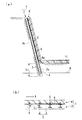
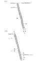
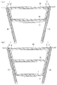
図1(a)に示すように、山留め合成壁1は、山留め壁本体2と、側壁6により構成されている。山留め壁本体2は、鉛直軸からみて背面2b側にもたれるように傾斜して配置されており、H形鋼よりなる鉄骨造の芯材4とソイルセメント3により構成されている。
前記芯材4は、地盤中における山留め位置の深さ方向に延在するとともに、図1(b)の平面図に示すように、複数が山留め位置の長さ方向Xに所定の配置間隔L1をもって並列配置されている。
また、前記ソイルセメント3は、原位置の土壌にセメント等の固化液を添加したセメント安定処理土であり、山留め位置の長さ方向Xに並列配置された複数の芯材4全てを内包するように打設されている。これにより、山留め壁本体2は、いわゆる地中連続壁に構成されている。
As shown in FIG. 1A, the mountain retaining
The
The
これら山留め壁本体2を地中連続壁とする構成は、山留め位置の長さ方向に対する前記芯材4の配置位置に制約が生じないため、隣り合う芯材4の配置間隔L1の調整が容易である。つまり、山留め壁本体2は、隣り合う前記芯材4の配置間隔L1を、山留め壁本体2の背面2bに作用すると想定される土圧や水圧の程度に応じて適宜可変することが可能な汎用性が高く施工性の良い合理的な構成となっている。
なお、本実施の形態では、山留め壁本体2を一般に広く知られているTRD工法にて構築するものである。ここで、TRD工法とは、地中の鉛直方向に挿入したチェーンソー型のカッターを回転させ、地盤を切削しながら水平方向に移動することで連続した溝を掘削し、これと同時に固化液と原位置土を混合・攪拌し、ソイルセメント地中連続壁を造成する工法であり、その手順は、後に示す山留め合成壁1の施工方法で詳述する。
Configuration for these earth retaining
In the present embodiment, the retaining wall
一方、該山留め壁本体2を鉛直軸からみて背面2b側にもたれるように傾斜して配置する構成は、従来のように鉛直状に山留め壁本体2を配置する場合と比較して、背面2bに作用する土圧を大幅に軽減できるものである。
また、このような構成により、山留め壁本体2の表面2a側に位置する地盤を根切りするにつれて、背面2bに作用する土圧により山留め壁本体2に起きあがる現象が生じるため、背面2b側の地盤が弛み土圧はさらに軽減する。したがって、山留め壁本体2は、これらの現象を考慮することにより、合理的な断面設計を実施できるものである。
On the other hand, the configuration in which the mountain wall
In addition, with such a configuration, as the ground located on the
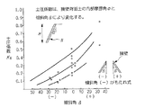
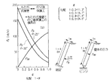
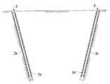
なお、山留め壁本体2を構築する際の傾斜角度について、例えば、山留め壁本体2の背面2b側の地盤の内部摩擦角φが30°の場合には、図3に示すように約0.5未満の勾配Nであれば山留め壁本体2を鉛直軸からみて背面2b側に傾斜させることが有効であり、勾配Nを0.2(傾斜角11.3°)、または0.3(傾斜角16.7°)と設定すると、図2に示すように土圧はそれぞれ、0.7倍、0.6倍に低減されることが分かる。
一般に、土圧係数KNは内部摩擦角φにより大きく変化するがこの比率はそれほど変化しないことが知られており、例に挙げた0.2または0.3程度の勾配Nであっても山留め壁本体2を鉛直軸からみて背面2b側に傾斜して配置する構成は、土圧の低減に大きな効果を有することが分かる。ここで用いた図2及び図3は、福岡正巳著「土圧の謎をやさしく解く」近代図書、2003年6月より抜粋したものである。
For example, when the internal friction angle φ of the ground on the
In general, it is known that the earth pressure coefficient K N varies greatly depending on the internal friction angle φ, but this ratio does not vary so much. Even if the gradient N is about 0.2 or 0.3, the retaining
上述する構成の山留め壁本体2は、先端部近傍に対して背面2bに作用する土圧の支持に必要な根入れ深さL2を確保した状態で表面2a側の地盤が根切りされており、表面2aが露出されている。この表面2aは、山留め壁本体2に内包されている前記芯材4による露出面4aが形成されるまでソイルセメント3をはつられており、図1(a)に示すように、該芯材4の露出面4aには、所定の離間間隔をもって、複数のスタッドジベル5が固着手段を介して固着されている。
Retaining
該スタッドジベル5は、山留め壁本体2の表面2aに沿って後打ちされる鉄筋コンクリート造の前記側壁6との定着(付着による一体化)を向上することを目的に設置されるものである。該側壁6は、山留め壁本体2の表面2a側に後に構築される地下構造物の躯体の一部であり、スタッドジベル5を介して山留め壁本体2と一体化されて、合成構造の山留め合成壁1が形成される。
The
なお、本実施の形態では、図1(a)に示すように、スタッドジベル5を前記芯材4による露出面4aの全面に対して一様に固着し、山留め合成壁1の全高を合成構造とする構成としているが、必ずしもこれにこだわるものではない。例えば、露出面4aの下半にのみ固着する、もしくは露出面4aの一部分に固着する等して、山留め合成壁1を部分的に合成構造とする構成としても良い。
また、前記スタッドジベル5には一般に広く用いられている頭部付きスタッドを用いているが、必ずしもこれにこだわるものではなく、側壁6を構成するコンクリートとの定着(付着による一体化)を向上できる形状の部材であれば、鋼材や鉄筋を溶接する等何れを用いても良い。
In the present embodiment, as shown in FIG. 1 (a), the
Moreover, although the stud with the head generally used widely is used for the said
このような構成の山留め合成壁1は、前記側壁6を備えることから地下構造物本体としての機能をも兼ねるものであり、山留め壁本体2を一体的に備えることにより、従来の山留め壁本体2を一体的に備えない場合と比較して側壁6の壁厚を大幅に低減している。
特に、図1に示すように、切梁を不要とする程度に山留め壁本体2を傾斜して配置し、山留め合成壁1に作用する土圧を低減している場合には、鉄筋コンクリート造の側壁6に応力がほぼ生じないことから、側壁6の壁厚を耐久性に支障のない程度まで一層低減することができる。
The mountain retaining
In particular, as shown in FIG. 1, when the retaining wall
また、これら山留め合成壁1には、山留め合成壁1の表面2a側に位置する根切り底11近傍に曲げ応力による大きな引張り力が作用する。しかし、前記山留め壁本体2を構成する芯材4がこれを負担するため、鉄筋コンクリート造の側壁6には引張り力がほぼ作用することがなく圧縮応力場となる。したがって、側壁6にはひび割れが生じにくくなり漏水を防止でき、山留め合成壁1を耐久性に富んだ構成とすることができる。
Further, a large tensile force due to a bending stress acts on the piled
さらに、山留め壁本体2の先端部近傍には背面2bに作用する土圧の支持に必要な根入れ深さL2を確保していることから、山留め合成壁1の高さが高い場合にも根入れ部で山留め壁本体2の曲げ耐力により抵抗できるため、山留め合成壁1を構築する際の高さに制約が小さくなり、汎用性の高い構成とすることができる。
なお、図1(a)に示すように、山留め壁本体2の先端部近傍を地盤中の支持層8に達する深さまで根入れし、富調合のソイルセメントで根固めすれば、山留め合成壁1が自身を含めた近傍の荷重を地盤に伝達する杭として機能するため、この部位への杭基礎の構築を省略することもできる。
Furthermore, since in the vicinity of the distal end portion Retaining
As shown in FIG. 1 (a), if the vicinity of the tip of the retaining wall
また、山留め壁本体2に適切な傾斜を確保できない、構築したい高さが高い、もしくは周辺地盤の水圧が大きい等、山留め壁本体2に生じる応力が大きい場合には、一般の山留め壁に多用されているように、山留め壁本体2の表面中段に腹起こしを設けて切梁を設置する構成としても良く、これにより山留め合成壁1に対して一層高い安全性を確保することが可能である。
In addition, when the stress generated in the mountain
ところで、本実施の形態では、図1(a)(b)に示すように、山留め壁本体2の表面2aに、施工性が良く安定した止水性能を発揮することで一般に知られているゴムアスファルト系の塗膜防水を塗布し、側壁6との間に防水層9を形成している。このような構成は、山留め合成壁1の止水性能を飛躍的に向上し、山留め合成壁1の耐久性能を一層高めるものである。
なお、このような防水層9は、必ずしもゴムアスファルト系の材料にこだわるものではなく、安定した防水性能を発現するものであれば、何れを用いても良い。また、該防水層9は山留め合成壁1に必ずしも設ける必要はない。
By the way, in this Embodiment, as shown to FIG. 1 (a) (b), it is generally known by the
Such a
上述する構成の山留め合成壁1を地盤中に構築するための、山留め合成壁の構築方法を以下に示す。
A method for constructing a mountain retaining composite wall for constructing the mountain retaining
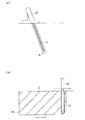
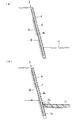
第1の工程では、図5(a)に示すように、地盤中における山留め位置に、鉛直軸からみて背面2bとなる側に傾斜させた山留め壁本体2を構築する。該山留め壁本体2は、先にも述べたように、一般に広く知られているTRD工法により構築する。その構築方法を簡略に示す。
まず、図4(a)に示すように、地盤上にTRD掘削機12をセットするとともに、地盤中の山留め位置にチェーンソー型のカッターポスト13を挿入する。このとき、カッターポスト13は、山留め壁本体2に持たせる傾斜角度に対応して鉛直軸より傾斜させた状態で、所定の深さまで建て込む。また、必要に応じて表層地盤改良を併用しても良い。
In the first step, as shown in FIG. 5 (a), a mountain
First, as shown in FIG. 4 (a), the
次に、図4(b)に示すように、前記TRD掘削機12を介してカッターポスト13を回転させながら地盤を掘削するとともに、カッターポスト13を山留め位置の長さ方向Xに移動し、山留め位置の長さ方向に連続した溝14を形成する。このとき同時に、セメントミルク等の固化液を溝14に注入し、該固化液と掘削した原位置の土砂と溝内で一様となるように攪拌してソイルセメント3を製造する。
Next, as shown in FIG. 4 (b), the ground is excavated while rotating the
この後、カッターポスト13の移動後の前記溝14中に、順次所定の離間間隔L1をもって複数の芯材4を建て込む。ここで、芯材4の建て込みには、ガイド等の治具を用いるなどして建て込み精度を確保する。前記ソイルセメント3が硬化して十分な強度が発現すると、図5(a)に示すように、山留め壁本体2が造成されることとなる。
Then, in the
上述したように、TRD工法を用いることにより、山留め壁本体2を山留め位置の長さ方向に連続した止水性の高い均質で等厚な連続地中壁として造成できる。また、全長にわたって高い精度で所定の傾斜角度を保持できるとともに、鉛直方向全層の土質を混合・攪拌するため、深度方向に強度のばらつきが少ない均質な壁体とすることができる、芯材4を任意の間隔で配置できる、といった効果を有することとなる。
As described above, by using the TRD method, the retaining wall
第2の工程では、前記山留め壁本体2が造成された後、図5(b)に示すように、山留め壁本体2の表面2a側の地盤を、該山留め壁本体2の先端部近傍に背面2bに作用する土圧の支持に必要な根入れ深さL2を確保した上で所定の深さまで根切りする。これにより露出した山留め壁本体2の表面2aを、図6(a)に示すように、芯材4に露出面4aが形成されるまではつった後、芯材4の露出面4aにスタッドジベル5を溶接等の固着手段を介して固着する。
In the second step, after the mountain retaining wall
第3の工程では、図6(b)に示すように、山留め壁本体2の表面側2aに形成された内の根切り底11に鉄筋コンクリート造の底盤7を構築する。このとき、該底盤7が後に構築する側壁6と一体化されるように、底盤7の配筋の際に、前記側壁6と向かい合う側の鉄筋7aの端部を前記芯材4の露出面4aと平行して延在するように配置しておくとともに、底盤7に側壁6とのアンカー6aを差し筋しておく。なお、鉄筋7aの端部の配置は必ずしもこれにこだわるものではなく、前記底盤7と側壁6とを一体化できる構成であれば、芯材4の露出面4aに直接溶接しても、何れの形状に配置しても良い。
In a 3rd process, as shown in FIG.6 (b), the
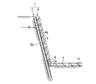
第4の工程では、図7に示すように、前記芯材4の露出面4aに設置した前記スタッドジベル5を内包するように、山留め壁本体2の表面2aに沿って一体的に鉄筋コンクリート造の側壁6を構築する。このとき、第3の工程で、前記底盤7より突出させた底盤7を構成する鉄筋7aの端部についても内包するようにコンクリートを打設する。
In the fourth step, as shown in FIG. 7, the reinforced concrete structure is integrally formed along the
このように、山留め合成壁1の構築方法は、工事に際して特別な技量や装置を要しないとともに、従来より一般に実施されている建築基準法を逸脱しない工法で構築できる方法であることから、作業性が良く工期を大幅に短縮することができる。
なお、山留め合成壁1の構築方法は、必ずしも上述する方法にこだわるものではなく、例えば、地上部と地下部の両者を有する構造物の構築に際し、地上部と地下階とを同時に施工できる工法として一般に知られている逆打ち工法を適用することも可能である。これら逆打ち工法を適用した山留め合成壁1の構築方法を以下に示す。
As described above, the construction method of the retaining wall
In addition, the construction method of the mountain retaining
まず、第1の工程では、先に述べたものと同様で、図8に示すように、地盤中の山留め位置に鉛直軸からみて背面2b側に所定の勾配を有して傾斜するように、芯材4とソイルセメント3よりなる地中連続壁よりなる山留め壁本体2を構築する。
次に、山留め壁本体2の表面2a側の地盤における根切り深さを複数層に分割し、最上層から最下層に向けて、以下に示す第2の工程から第4の工程を各層毎に対して段階的に実施し、図9(b)に示すように、地下構造物とともに山留め合成壁1を構築する。
第2の工程では、地下構造物の分割層の床スラブを構築できる深さまで地盤を根切りした後、山留め壁本体2の表面2aを芯材4による露出面4aが形成されるまではつり、該芯材4の露出面4aにスタッドジベル5を設置する。第3の工程では、根切り底11に分割層の床10を構築する。第4の工程では、図9(a)に示すように、前記芯材4の露出面4aに設置した前記スタッドジベル5を内包するように、山留め壁本体2の表面2aに鉄筋コンクリート造の側壁6を構築する。
なお、最下層に達した際には、第3の工程で根切り底に、床10に代わって鉄筋コンクリート造の底盤7を構築する。
First, in the first step, as described above, as shown in FIG. 8, the mountain mounting position in the ground is inclined with a predetermined gradient on the
Next, the root cutting depth in the ground on the
In the second step, after the ground is rooted to a depth at which the floor slab of the divided layer of the underground structure can be constructed, the
When the bottom layer is reached, a reinforced concrete
このように山留め壁本体2の表面2a側に位置する地盤の根切り深さを複数層に分割し、各層毎で段階的に掘削することにより、並行して床10や図示しない梁、柱等地下構造物を構築できることから、これらの山留め合成壁1のみでなく地下構造物の自重で土圧の一部をキャンセルすることができる。また、底盤7より上方に床10や梁が構築されることから、これらが躯体切梁として機能することとなり、山留め壁本体2に作用する土圧を大きく低減することができ、山留め壁本体2の変形を抑制できる。
In this way, the root cutting depth of the ground located on the
なお、上述する山留め合成壁1の構築方法において、背面2b側の地盤中の水位を低下できる場合には、山留め壁本体2を構築する第1の工程の後全ての工程が終了するまで、図5(b)に示すように、水位を低下させることが効果的である。これにより、根切り時に山留め壁本体2に作用する水圧を低減させることができ、さらには、後打ちする前記側壁6の断面をも合理化できることとなる。なお、低下させた水位は、全ての工程が終了した後であれば現状回復を図っても、側壁6と山留め壁本体2とが一体化された山留め合成壁1で抵抗できるため、問題が生じることはない。
また、第2の工程で山留め壁本体2の表面2a側に位置する地盤の根切り作業中に、背面2b側近傍を所定の深さまで掘削すれば、山留め壁本体2に作用する土圧を低減することができ、より安全で精度良く作業を実施できる。
In addition, in the construction method of the retaining wall
In addition, during excavation of the ground near the
上記した構成からなる山留め合成壁1によれば、山留め壁本体2が背面2b側に傾斜配置されているため、土圧応力を大きく低減することが可能となる。これに伴い、切梁の簡略化もしくは傾斜勾配を調整することにより切梁を不要にできる等、施工性を向上することが可能になるとともに、工費削減、工期短縮に寄与することが可能となる。
According to the mountain retaining
また、山留め壁本体2に作用する土圧が低減することにより、山留め壁本体2の表面に沿って一体的に後打ちする側壁6の壁厚を小さくすることが可能となる。特に、前記山留め壁本体2に切梁を設けない山留め合成壁1の場合には、鉄筋コンクリート造の側壁6にほとんど応力を生じることがないため、壁厚を耐久性に問題のない程度にまで低減することが可能となる。
Further, the earth pressure acting on the mountain
さらに、山留め壁本体2と鉄筋コンクリート造の側壁6が、山留め壁本体2の芯材4に備えたスタッドジベル5を介して一体化されることから、山留め合成壁1の根切り底11と当接する位置近傍に生じる曲げ応力による大きな引張り力を芯材4が処理するため、側壁6にはほぼ引張り力が作用せず圧縮応力場となる。このため、ひび割れが生じにくく、漏水や耐久性の問題が生じにくい性能の高い構成とすることが可能となる。
Further, the mountain retaining wall
また、前記山留め壁本体2が、複数の芯材4をソイルセメント3で埋設してなり、地盤における山留め位置の長さ方向Xに連続する地中連続壁に構成されることから、山留め位置の長さ方向Xに対する芯材4の配置間隔を任意に設置できるため、山留め壁本体2に生じる土圧に応じて容易に配置間隔を可変することができ、芯材4の合理的な配置計画を図ることが可能となる。
Further, the mountain retaining wall
一方で、山留め合成壁1は、地下構造物の躯体を構成する鉄筋コンクリート造の側壁6を一体的に備えているため、地下構造物の躯体の一部として本体利用が可能となり、例えば、地下階を有する免震構造物の免震ピットを構成する外周ドライエリアの壁、機械設備により階高が大きくなる地下階の外壁、造船ドックの擁壁等に適用することにより、曲げモーメントを山留め壁本体2を構成する芯材4が有効に負担して、山留め合成壁を有効活用することが可能となる。
On the other hand, since the mountain retaining
なお、山留め合成壁1を構成する山留め壁本体2の先端部近傍を、地盤中の支持層8に位置させ根固めすることにより、山留め壁本体2を杭として機能させることができることから、山留め合成壁1を含む近傍の荷重を山留め壁本体2を介して地盤に伝達できるため、これらの部位への杭基礎の構築を省略でき、工費を大幅に削減することが可能となる。
In addition, since the mountain retaining wall
また、山留め壁本体2と側壁6との間に防水層9を形成して山留め合成壁1とすることにより、漏水を抑制できる等止水性能を飛躍的に向上することができるため、山留め合成壁1の耐久性をより向上することが可能となる。
Moreover, since the
前記山留め合成壁1の構築方法によれば、工事に際して特別な技量や装置を要しないとともに、従来より一般に実施されている建築基準法を逸脱しない工法で構築できる方法であることから、作業性が良く工期を工費削減および工期短縮に大きく寄与することが可能となる。
According to the construction method of the above-mentioned mountain retaining
また、山留め壁本体2を背面2b側に傾斜して構築することから、山留め壁本体2の表面側2aの地盤に対する根切り作業が進行するにつれて、根切りに伴い増大する土圧により山留め壁本体2はやや起きあがる現象が生じる。これにより、山留め壁本体2の背面2b側の地盤が弛んで土圧が減少することとから、山留め壁本体2はこれらの現象を考慮してより合理的な断面設計を行うことが可能となる。
Further, since the mountain retaining wall
さらに、前記山留め壁体2に対して土圧の支持に必要な根入れ深さを確保した上で根切り作業が行われることから、山留め壁本体2の根入れ部で曲げ耐力により土圧に抵抗できるため、一般に適用されているもたれ式擁壁では不安定になるような高さであっても、山留め合成壁1を適用することが可能となる。
Furthermore, since the root cutting work is performed after securing the depth of penetration necessary for supporting the earth pressure with respect to the
逆打ち工法を適用した山留め合成壁1の構築方法によれば、前記山留め壁本体2の表面2a側に位置する地盤の根切り深さを複数層に分割して上層から下層に向けて段階的に掘削しながら床、梁、柱等、地下構造物を並行して施工できるため、工期を大幅に短縮できるとともに、施工にかかる近隣周辺地盤への影響を最小限に抑制することが可能となる。
一方で、これら地下構造物の自重を利用して土圧の一部をキャンセルできることから、作業の安全性がより向上するとともに、各層毎に床や梁等が構築されることにより、これらが躯体切梁として機能することから、山留め合成壁1に作用する土圧を大きく低減でき、山留め壁本体2の変形を小さくすることが可能となる。
According to the construction method of the retaining wall
On the other hand, since some of the earth pressure can be canceled using the weight of these underground structures, the safety of the work is further improved, and the floors and beams are constructed for each layer. Since it functions as a beam, the earth pressure acting on the retaining wall
該山留め合成壁1の構築に際し、山留め壁本体2の表面2a側に位置する地盤の根切り作業時に、併せて背面2b側近傍を掘削することにより、山留め壁本体2に作用する土圧を低減することが可能となり、作業時のより高い安全性を確保することが可能となる。
During construction of the retaining wall
また、山留め合成壁1の構築に際し、山留め壁本体2を構築した後、全ての工程が終了するまで、前記山留め壁本体2の背面2b側の水位を低下させることにより、土圧に加えて山留め壁本体2の背面2bに作用する水圧を低減させることができるとともに、山留め壁本体2の表面2aに沿って一体的に後打ちする前記側壁6の断面を合理化することが可能となる。
なお、低下させた水位は、全ての工程が終了した後であれば現状回復を図っても、山留め壁本体2と鉄筋コンクリート造の側壁6よりなる合成構造の山留め合成壁1で抵抗することが可能である。
Further, in constructing the retaining wall
It should be noted that the lowered water level can be resisted by the
以上、本発明に係る山留め合成壁1、及び山留め合成壁の構築方法に係る実施の形態について説明したが、本発明は上記した実施の形態に限定されるものではなく、その趣旨を逸脱しない範囲で適宜変更可能である。
As mentioned above, although embodiment concerning the construction method of the retaining wall
1 山留め合成壁
2 山留め壁本体
3 ソイルセメント
4 芯材
5 スタッドジベル
6 側壁
7 底盤
8 支持層
9 防水層
10 床
11 根切り底
12 TRD掘削機
13 カッターポスト
14 溝
DESCRIPTION OF
Claims (7)
該山留め壁本体の表面に後打ちする鉄筋コンクリート造の側壁よりなり、
前記山留め壁本体は、前記山留め位置に挿入したカッターポストを回転させて地盤を掘削しながら該カッターポストを前記山留め位置の長さ方向に移動させて該長さ方向に連続した溝を形成するとともに、該溝に固化液を注入して掘削土砂と攪拌させてソイルセメントを製造し、さらに、前記溝の中に複数の鉄骨造の芯材を所定の離間間隔をもって建て込むことにより構築されており、
前記芯材には、山留め壁本体の表面に形成された露出面の少なくとも一部分に複数のスタッドジベルを設置されて、
前記側壁に該スタッドジベルが内包されることにより、山留め壁本体と側壁とが一体化した合成構造に構築されることを特徴とする山留め合成壁。 A plurality of steel cores that extend in the depth direction of the retaining positions in the ground and are arranged in parallel in the length direction of the retaining positions with a predetermined spacing, and a soil cement that embeds the plurality of the core materials Constructed, continuous in the length direction of the mountain retaining position, and inclined to the back side with respect to the vertical axis, the penetration depth required to support earth pressure acting on the back surface is near the tip The secured retaining wall body,
It consists of a reinforced concrete side wall that is struck on the surface of the mountain retaining wall body,
The retaining wall main body rotates the cutter post inserted in the retaining position to excavate the ground, and moves the cutter post in the longitudinal direction of the retaining position to form a continuous groove in the longitudinal direction. In addition, it is constructed by injecting solidified liquid into the groove and stirring it with the excavated earth and sand to produce a soil cement, and further constructing a plurality of steel cores in the groove with a predetermined spacing interval. ,
The core member is provided with a plurality of stud dowels on at least a part of an exposed surface formed on the surface of the retaining wall main body,
The stud retaining wall is constructed in a synthetic structure in which the retaining wall main body and the sidewall are integrated by including the stud gibel in the sidewall.
前記山留め壁本体の先端部近傍が、富調合のソイルセメントで形成されるとともに、地盤中の支持層に位置することを特徴とする山留め合成壁。 The mountain retaining composite wall according to claim 1,
A mountain retaining synthetic wall characterized in that the vicinity of the tip of the mountain retaining wall body is formed of a well-mixed soil cement and is located in a support layer in the ground.
前記山留め壁本体と側壁との間に、防水層が備えられることを特徴とする山留め合成壁。 The mountain retaining composite wall according to claim 1 or 2,
A mountain retaining synthetic wall characterized in that a waterproof layer is provided between the mountain retaining wall main body and the side wall.
背面に作用する土圧の支持に必要な根入れ深さを前記山留め壁本体の先端部近傍に確保した上で、前記山留め壁本体の表面側に位置する地盤を所定の深さまで根切りした後、山留め壁本体の表面を前記芯材に露出面が形成されるまではつり、該芯材の露出面にスタッドジベルを設置する第2の工程と、
前記山留め壁本体の表面側に形成された根切り底に、鉄筋コンクリート造の底盤を構築する第3の工程と、
前記芯材の露出面に設置した前記スタッドジベルを内包するように、山留め壁本体の表面に沿って鉄筋コンクリート造の側壁を構築する第4の工程により構成されることを特徴とする山留め合成壁の構築方法。 While rotating the cutter post inserted at the mountain retaining position in the ground to excavate the ground, the cutter post is moved in the length direction of the mountain retaining position to form a continuous groove in the length direction. A solid cement is poured into the excavated soil to produce a soil cement, and a plurality of steel cores are installed in the groove at a predetermined spacing, so that a plurality of steel cores are installed at the pile position. the earth retaining wall body made of a diaphragm wall with the soil cement and the core, a first step of constructing is inclined to the rear side with respect to a vertical axis,
After securing the necessary depth to support the earth pressure acting on the back surface in the vicinity of the tip of the retaining wall body, the ground located on the surface side of the retaining wall body is rooted to a predetermined depth. A second step of suspending the surface of the retaining wall main body until an exposed surface is formed on the core material, and installing a stud gibber on the exposed surface of the core material;
A third step of constructing a reinforced concrete bottom plate on the rooted bottom formed on the surface side of the retaining wall body;
A composite wall of a retaining wall characterized by comprising a fourth step of constructing a reinforced concrete side wall along the surface of the retaining wall main body so as to enclose the stud gibber installed on the exposed surface of the core material. Construction method.
第1の工程の後、前記山留め壁本体の表面側の地盤を掘削する際の根切り深さを複数層に分割し、最上層から最下層に向けて各層毎で段階的に第2の工程、鉄筋コンクリート造の底盤に代わり各層毎の根切り底の上に床を構築する第3の工程、および第4の工程を繰り返す逆打ち工法を実施し、
最下層では、第2の工程、根切り底に前記底盤を構築する第3の工程、及び第4の工程を実施することを特徴とする山留め合成壁の構築方法。 In the construction method of the retaining wall composite wall according to claim 4,
After the first step, the root cutting depth when excavating the ground on the surface side of the retaining wall main body is divided into a plurality of layers, and the second step is performed step by step from the top layer to the bottom layer. The third step of constructing the floor on the rooted bottom of each layer instead of the reinforced concrete bottom plate, and the reverse driving method of repeating the fourth step,
In the lowest layer, the construction method of the mountain retaining synthetic wall is characterized in that the second step, the third step of constructing the bottom plate on the rooted bottom, and the fourth step are performed.
第2の工程で、前記山留め壁本体の背面近傍における地盤を、所定深さまで掘削することを特徴とする山留め合成壁の構築方法。 In the construction method of the retaining wall composite wall according to claim 4 or 5,
In the second step, a method for constructing a mountain retaining composite wall, wherein the ground in the vicinity of the back surface of the mountain retaining wall main body is excavated to a predetermined depth.
第1の工程の後、全ての工程が終了するまで、前記山留め壁本体の背面側の水位を低下させることを特徴とする山留め合成壁の構築方法。 In the construction method of the retaining wall composite wall according to any one of claims 4 to 6,
After the first step, the water level on the back side of the mountain retaining wall main body is lowered until all the steps are completed.
Priority Applications (1)
| Application Number | Priority Date | Filing Date | Title |
|---|---|---|---|
| JP2003318347A JP4329068B2 (en) | 2003-09-10 | 2003-09-10 | Yamauchi composite wall and method for constructing Yamauchi composite wall |
Applications Claiming Priority (1)
| Application Number | Priority Date | Filing Date | Title |
|---|---|---|---|
| JP2003318347A JP4329068B2 (en) | 2003-09-10 | 2003-09-10 | Yamauchi composite wall and method for constructing Yamauchi composite wall |
Publications (2)
| Publication Number | Publication Date |
|---|---|
| JP2005083123A JP2005083123A (en) | 2005-03-31 |
| JP4329068B2 true JP4329068B2 (en) | 2009-09-09 |
Family
ID=34417648
Family Applications (1)
| Application Number | Title | Priority Date | Filing Date |
|---|---|---|---|
| JP2003318347A Expired - Fee Related JP4329068B2 (en) | 2003-09-10 | 2003-09-10 | Yamauchi composite wall and method for constructing Yamauchi composite wall |
Country Status (1)
| Country | Link |
|---|---|
| JP (1) | JP4329068B2 (en) |
Families Citing this family (6)
| Publication number | Priority date | Publication date | Assignee | Title |
|---|---|---|---|---|
| JP5144296B2 (en) * | 2008-02-08 | 2013-02-13 | 鹿島建設株式会社 | Self-supporting mountain retaining wall method |
| JP5228862B2 (en) * | 2008-12-04 | 2013-07-03 | 株式会社大林組 | Underground structure, construction method of underground structure |
| JP4683138B2 (en) * | 2009-03-25 | 2011-05-11 | 株式会社大林組 | Retaining wall structure, method for constructing retaining wall structure |
| JP4862908B2 (en) * | 2009-03-25 | 2012-01-25 | 株式会社大林組 | Retaining wall structure, method for constructing retaining wall structure |
| JP5440145B2 (en) * | 2009-12-16 | 2014-03-12 | 株式会社大林組 | Yamadome wall structure |
| JP6298622B2 (en) * | 2013-11-25 | 2018-03-20 | 株式会社大林組 | Guide device used for placing the core material of the oblique retaining wall, method for placing the core material of the oblique retaining wall, and method for installing the guide device |
-
2003
- 2003-09-10 JP JP2003318347A patent/JP4329068B2/en not_active Expired - Fee Related
Also Published As
| Publication number | Publication date |
|---|---|
| JP2005083123A (en) | 2005-03-31 |
Similar Documents
| Publication | Publication Date | Title |
|---|---|---|
| US9567720B2 (en) | Offshore platform for a marine environment | |
| JP4281567B2 (en) | Reinforcement structure of existing pier foundation and reinforcement method of existing pier foundation | |
| JP7017541B2 (en) | Improvement structure and improvement method of existing sheet pile type quay | |
| AU2012313196B2 (en) | Partially floating marine platform for offshore wind-power, bridges and marine buildings, and construction method | |
| KR102254227B1 (en) | High-strength concrete pile structure with pc pile cap and construction method | |
| JP3850785B2 (en) | Caisson laying method using main foundation pile | |
| JP4329068B2 (en) | Yamauchi composite wall and method for constructing Yamauchi composite wall | |
| KR20060092552A (en) | Construction method of unsupported downward frame using cast-in-place pile | |
| JP5228862B2 (en) | Underground structure, construction method of underground structure | |
| KR102580530B1 (en) | Bridge lower structure of assembly type having elastic duct coupler of socket type, and construction method for the same | |
| JP5077857B1 (en) | Seismic reinforcement structure of existing structure foundation by composite ground pile foundation technology | |
| JP6855665B2 (en) | Pile foundation structure and how to reinforce existing piles | |
| JP7028728B2 (en) | Joint structure of foundation pile and foundation slab | |
| JP4833949B2 (en) | Concrete integrated structure pillar | |
| JP2004027727A (en) | Foundation pile and construction method of foundation pile | |
| CN111997089B (en) | Construction method based on assembled self-balancing type pushing working pit system | |
| JP2019127746A (en) | Flotation inhibition structure and inverted construction method | |
| JP6130991B2 (en) | Foundation structure | |
| JP4837618B2 (en) | Caisson press-in method | |
| JP6534026B2 (en) | Seismic isolation building and its construction method | |
| KR102157976B1 (en) | underwater structure to be connected to pile foundation by using bracket | |
| JP7499382B1 (en) | Earthquake-resistant reinforcement structure | |
| JP6000414B2 (en) | Pile foundation reconstruction method and pile foundation structure | |
| JP4451555B2 (en) | Reverse hammering method | |
| JP4344733B2 (en) | Seismic reinforcement structure for existing pile foundation structures |
Legal Events
| Date | Code | Title | Description |
|---|---|---|---|
| A621 | Written request for application examination |
Free format text: JAPANESE INTERMEDIATE CODE: A621 Effective date: 20060301 |
|
| A977 | Report on retrieval |
Free format text: JAPANESE INTERMEDIATE CODE: A971007 Effective date: 20080129 |
|
| A131 | Notification of reasons for refusal |
Free format text: JAPANESE INTERMEDIATE CODE: A131 Effective date: 20080507 |
|
| A521 | Written amendment |
Free format text: JAPANESE INTERMEDIATE CODE: A523 Effective date: 20080702 |
|
| TRDD | Decision of grant or rejection written | ||
| A01 | Written decision to grant a patent or to grant a registration (utility model) |
Free format text: JAPANESE INTERMEDIATE CODE: A01 Effective date: 20090507 |
|
| A01 | Written decision to grant a patent or to grant a registration (utility model) |
Free format text: JAPANESE INTERMEDIATE CODE: A01 |
|
| A61 | First payment of annual fees (during grant procedure) |
Free format text: JAPANESE INTERMEDIATE CODE: A61 Effective date: 20090604 |
|
| R150 | Certificate of patent or registration of utility model |
Free format text: JAPANESE INTERMEDIATE CODE: R150 |
|
| FPAY | Renewal fee payment (event date is renewal date of database) |
Free format text: PAYMENT UNTIL: 20120626 Year of fee payment: 3 |
|
| LAPS | Cancellation because of no payment of annual fees |