JP6534026B2 - Seismic isolation building and its construction method - Google Patents
Seismic isolation building and its construction method Download PDFInfo
- Publication number
- JP6534026B2 JP6534026B2 JP2014142552A JP2014142552A JP6534026B2 JP 6534026 B2 JP6534026 B2 JP 6534026B2 JP 2014142552 A JP2014142552 A JP 2014142552A JP 2014142552 A JP2014142552 A JP 2014142552A JP 6534026 B2 JP6534026 B2 JP 6534026B2
- Authority
- JP
- Japan
- Prior art keywords
- core
- foundation
- seismic isolation
- temporary
- outer peripheral
- Prior art date
- Legal status (The legal status is an assumption and is not a legal conclusion. Google has not performed a legal analysis and makes no representation as to the accuracy of the status listed.)
- Active
Links
Images
Landscapes
- Foundations (AREA)
- Buildings Adapted To Withstand Abnormal External Influences (AREA)
Description
本発明は、免震建物及びその施工方法に関する。 The present invention relates to a seismic isolation building and its construction method.
従来、免震建物として、地下階に免震装置を介在させた基礎免震層を設けた基礎免震構造が知られている(例えば、特許文献1参照)。
特許文献1には、地下階の底部に存在する建物の基礎が高さ方向の段差を有する既存建物の免震化工法であって、各高さの地下階において免震装置を介在させた基礎免震層を設けた既存建物の免震建物について記載されている。
Conventionally, as a base isolation building, there is known a base isolation structure provided with a base isolation layer in which a base isolation device is interposed in a basement floor (see, for example, Patent Document 1).
In Patent Document 1, the foundation of a building existing at the bottom of a basement floor is a seismic isolation method for an existing building having steps in the height direction, and a foundation in which a base isolation system is interposed in the basement floor at each height. It describes about the seismic isolation building of the existing building which provided the seismic isolation layer.
しかしながら、上述した従来の基礎免震構造では、基礎梁形状であることが一般的であり、さらに地下に免震層を設けるために、施工時において建物の基礎全体にわたって地盤を深く掘削する必要があることから、コストが増大し、工期が長くなるうえ、施工品質が低下するという問題があった。 However, in the above-described conventional base isolation structure, it is general to have a foundation beam shape, and in order to provide a base isolation layer further underground, it is necessary to dig the ground deeply throughout the foundation of the building at the time of construction. As a result, there is a problem that the cost increases, the construction period becomes long, and the construction quality decreases.
本発明は、上述する問題点に鑑みてなされたもので、地下掘削の数量を少なく抑え、施工にかかるコストや工期を低減することができるうえ、施工品質を確保することができる免震建物及びその施工方法を提供することを目的とする。 The present invention has been made in view of the above-mentioned problems, and it is possible to reduce the number of underground excavations, to reduce the cost and construction period for construction, and to provide a seismically isolated building capable of securing construction quality. The purpose is to provide the construction method.
上記目的を達成するため、本発明に係る免震建物では、建物のコア部を支持するコア基礎部が、前記コア部の外周部分をなす建物のコア外周部を支持する外周基礎部よりも基礎底が深くなる構造の免震建物であって、前記コア基礎部と前記外周基礎部とに打設された基礎杭と、前記コア基礎部の土留め部として設けられる山留め壁と、前記外周基礎部に打設されるマットスラブに埋設されることによって本設として機能するとともに、前記山留め壁の上端に接続され、連結鉄筋が埋設された仮設土間コンクリートと、前記外周基礎部に設けられ、梁鉄筋が前記連結鉄筋を介して前記仮設土間コンクリートと一体で埋設された仮設梁と、前記コア基礎部の基礎底に設けられ、前記コア基礎部に打設されるマットスラブに埋設されることによって本設として機能する仮設鉄骨柱と、前記コア基礎部のマットスラブ上に設けられるコア免震装置と、前記コア外周部の地上階の鉄骨に設けられる中間免震装置と、を備え、前記梁鉄筋と前記連結鉄筋は、前記外周基礎部において前記仮設梁と前記山留め壁との間に打設されている前記基礎杭の杭頭を囲うように配筋されていることを特徴としている。 In order to achieve the above object, in the seismic isolation building according to the present invention, the core base portion supporting the core portion of the building is more basic than the outer portion supporting the core outer peripheral portion of the building forming the outer peripheral portion of the core portion. A base isolation structure having a deep bottom, wherein a foundation pile is installed on the core foundation portion and the outer periphery foundation portion, a retaining wall provided as a earth retaining portion of the core foundation portion, and the outer periphery foundation It is provided in temporary concrete between soils connected to the upper end of the retaining wall and embedded in the connecting rebar and installed in the outer peripheral foundation, while functioning as a main installation by being embedded in a mat slab cast in a part a temporary beam reinforcing bars are embedded in the temporary earthen concrete and integrally through the connecting reinforcement, provided basic bottom of the core foundation, by being embedded in the mat slab is Da設in the core base part With a temporary steel columns that function as set, and the core isolator provided on the mat slab of the core base portion, and an intermediate isolator provided on the ground floor of steel of the core outer peripheral portion, the beam rebar And the connection reinforcing bars are arranged so as to surround a pile head of the foundation pile which is placed between the temporary beam and the retaining wall in the outer peripheral foundation portion .
また、本発明に係る免震建物の施工方法では、建物のコア部を支持するコア基礎部が、前記コア部の外周部分をなす建物のコア外周部を支持する外周基礎部よりも基礎底が深くなる構造の免震建物の施工方法であって、前記コア基礎部の土留め部として山留め壁を設ける工程と、コンクリートを打設することで連結鉄筋を埋設し、前記外周基礎部に打設されるマットスラブに埋設されることによって本設として機能する仮設土間コンクリートを設ける工程と、前記外周基礎部においてコンクリートを打設することで梁鉄筋を前記仮設土間コンクリートと一体で埋設することにより仮設梁を設ける工程と、該仮設土間コンクリートの一部を前記山留め壁の上端に接続する工程と、前記コア基礎部の基礎底に仮設鉄骨柱を設け、該仮設鉄骨柱を前記コア基礎部に打設されるマットスラブに埋設することにより本設として機能させる工程と、前記コア基礎部のマットスラブ上にコア免震装置を設ける工程と、前記コア外周部の地上階の鉄骨に中間免震装置を設ける工程と、を有することを特徴としている。 Further, in the method of constructing a seismically isolated building according to the present invention, the core base portion supporting the core portion of the building has a base bottom more than the outer peripheral portion supporting the core outer peripheral portion of the building forming the outer peripheral portion of the core portion. It is a construction method of the base isolation structure of the structure which becomes deep, and the process of providing a retaining wall as the earth retaining portion of the core foundation portion and embedding the connecting rebar by placing concrete and placing it in the outer periphery foundation portion And a process of providing temporary concrete between soils which functions as a permanent structure by being buried in a mat slab, and temporary reinforcement by embedding the rebar beam integrally with the temporary concrete between soils by placing the concrete in the outer peripheral foundation portion. a step of providing the beam, a step of connecting a portion of the temporary earthen concrete to the upper end of the earth retaining wall, a temporary steel columns underlying a bottom of the core base portion is provided, the temporary steel columns before A step function as the set by embedding the mat slab is Da設the core base portion, a step of providing a core isolator on the mat slab of the core base portion, the ground floor of steel of the core outer peripheral portion Providing an intermediate seismic isolation device at the same time.
本発明では、外周基礎部の基礎底に打設された仮設土間コンクリートをコア基礎部に設けられる山留め壁の上端に接続させることで、仮設土間コンクリートが山留め壁のバックアンカーとして機能し、山留め壁が倒れる方向と反対側に引張り支持し、山留め壁が倒れるのを防止することができる。そのため、コア基礎部の山留め壁に一般的に設ける必要がある切り梁を省略することができ、コストの低減を図ることができる。
そして、切り梁の影響を受けずにコア部の土工事、躯体工事を施工することができるので、そのコア基礎部における切り梁の架け払しの作業が不要となり、工期の短縮を図ることができる。また、切り梁を省略できるので、掘削したコア基礎部の基礎底において、免震基礎部の鉄筋、型枠を先行して施工することができる。
In the present invention, by connecting the temporary soil concrete installed in the bottom of the outer foundation to the upper end of the retaining wall provided in the core foundation, the temporary soil concrete functions as a back anchor for the retaining wall, and the retaining wall Can be supported by pulling in the opposite direction to the direction in which it falls, so that the retaining wall can be prevented from falling. Therefore, a cutting beam generally required to be provided on the retaining wall of the core foundation can be omitted, and the cost can be reduced.
And since earthwork and frame work of the core part can be constructed without receiving the influence of the cutting beam, the work of cutting and laying the cutting beam in the core foundation part becomes unnecessary, and the construction period can be shortened. it can. In addition, since the cutting beam can be omitted, the reinforcing bar of the seismic isolation base portion and the formwork can be applied in advance in the foundation bottom of the excavated core foundation portion.
また、コア基礎部の基礎底における杭直上に仮設鉄骨柱を設けることで、コア基礎部にマットスラブのコンクリート打設する前の段階において、仮設鉄骨柱上に本設の鉄骨柱を建て込む作業を早期に開始することができる。つまり、コア基礎部におけるマットスラブのコンクリート打設に伴う土工事と仮設鉄骨柱上の鉄骨の建込み作業とを同時に行うことができるので、工程の短縮を図ることができる。 In addition, by placing a temporary steel frame column directly above the pile at the bottom of the core foundation, work to build a permanent steel column on the temporary steel column at the stage before putting concrete in the mat slab on the core foundation. You can start early. That is, since the earth work accompanying the concrete placing of the mat slab in the core foundation portion and the construction work of the steel frame on the temporary steel frame column can be simultaneously performed, the process can be shortened.
また、外周基礎部にマットスラブを打設するとともに、コア外周部の地上階の鉄骨に中間免震装置を設ける構造となるので、その外周基礎部の基礎掘削底上に直接、基礎梁や免震装置を設ける必要がなく、基礎掘削底の深さを小さく抑えることができ、掘削土量や躯体数量の低減を図ることができる。
しかも、外周基礎部の基礎底の位置が浅い位置となるので、基礎掘削底を常水面以上の高さに変更することが可能となる。その場合には、地下水の排水が不要になり、排水設備を設けずにすむうえ、常水面よりも上部での作業となって地下水の無い状態で他の施工を行うことができるので、施工性が向上するという利点がある。
In addition, since a mat slab is cast on the outer periphery foundation portion and an intermediate seismic isolation device is provided on the steel frame of the ground floor of the core outer periphery portion, foundation beams and isolation are directly installed on the foundation excavated bottom of the outer periphery foundation portion. There is no need to provide a seismic device, the depth of the bottom of the foundation can be kept small, and the amount of soil excavated and the number of frames can be reduced.
And since the position of the foundation bottom of a perimeter foundation part becomes a shallow position, it becomes possible to change a foundation excavated bottom to the height more than a usual water surface. In that case, drainage of ground water becomes unnecessary, and there is no need to provide drainage equipment, and work can be performed on the upper side of the surface of ordinary water, and other construction can be performed in the absence of groundwater. Has the advantage of improving
また、本発明に係る免震建物では、前記コア免震装置の免震基礎は、プレキャストコンクリート製により形成されていることが好ましい。 Further, in the seismic isolation building according to the present invention, it is preferable that the seismic isolation foundation of the core seismic isolation device is formed of precast concrete.
この場合には、コア基礎部におけるマットスラブの打設後において、コア免震装置の免震基礎の設置時間を短縮することができる。
また、免震基礎がプレキャストコンクリート製であるので、現場で施工する場合に比べて施工精度の向上を図ることができる。
In this case, the installation time of the seismic isolation foundation of the core seismic isolation device can be shortened after the placement of the mat slab in the core foundation portion.
In addition, since the seismic isolation foundation is made of precast concrete, the construction accuracy can be improved as compared with the case of construction on site.
また、本発明に係る免震建物の施工方法では、前記外周基礎部の土留め部は、地盤改良により施工されていることが好ましい。 Moreover, in the construction method of the seismic isolation building which concerns on this invention, it is preferable that the earth retaining part of the said outer periphery base part is constructed by ground improvement.
この場合には、外周基礎部の法面を掘削時に地盤改良し、土型枠として機能させることが可能となるので、山留め(親杭横矢板)や切り梁を省略することができ、コストの低減を図ることができる。 In this case, it is possible to improve the ground surface of the outer peripheral foundation portion at the time of excavation and make it function as a soil formwork, so it is possible to omit pile retaining (parent pile lateral arrow plate) and cutting beams. The reduction can be achieved.
本発明の免震建物及びその施工方法によれば、地下の免震基礎部を減らした構造とすることで、地下掘削の数量を少なく抑え、施工にかかるコストや工期を低減することができるうえ、施工品質を確保することができる。 According to the seismic isolation building of the present invention and the construction method thereof, the number of underground excavations can be reduced, and the cost and time required for construction can be reduced, by adopting a structure in which the seismic isolation base portion in the underground is reduced. , The construction quality can be secured.
以下、本発明の実施の形態による免震建物及びその施工方法について、図面に基づいて説明する。 Hereinafter, a seismic isolation building and its construction method according to an embodiment of the present invention will be described based on the drawings.
図1に示すように、本実施の形態による免震建物1は、多層階での建物であって、平面視の中央部分にコア部1Aを有し、そのコア部1Aの地下階に基礎免震層M1を設けるとともに、コア部1Aを除いたコア外周部1Bの地上階部分に中間免震層M2を設けた構造となっている。
As shown in FIG. 1, the seismic isolation building 1 according to the present embodiment is a multi-story building, and has a
この免震建物1は、コア部1Aを支持し基礎免震層M1が設けられるコア基礎部2Aが、コア外周部1Bを支持する部分の外周基礎部2Bよりも基礎底がさらに深い位置まで掘り下げられた構造となっている。それぞれの基礎部2A、2Bの基礎底には、全面にわたってコンクリート打設によって施工されるマットスラブ3が設けられており、そのマットスラブ3を介して免震建物1の鉄骨4(コア部鉄骨4A、外周部鉄骨4B)が建て込まれている。各基礎部2A、2Bには、適宜な位置に複数本の基礎杭2、2、…が打設されている。
ここで、マットスラブ3のうちコア基礎部2Aに施工されるものを符号3Aで示し、外周基礎部2Bに施工されるものを符号3Bで示す。
In this seismic isolation building 1, the
Here, among the
基礎免震層M1は、コア基礎部2Aに施工されるマットスラブ3A上に直接、コア免震装置7Aが設けられた構成となっている。
中間免震層M2は、外周基礎部2Bに建て込まれる外周部鉄骨4Bの地上階の最下層に設けられる鉄骨梁42上に中間免震装置7Bが設けられた構成となっている。
The base seismic isolation layer M1 has a configuration in which the core
The intermediate seismic isolation layer M2 is configured such that the intermediate
また、免震建物1は、外周基礎部2Bの基礎底に打設されるマットスラブ3Bに埋設されることによって本設として機能する仮設土間コンクリート5(図2参照)と、コア基礎部2Aの基礎底に設けられ、コア基礎部2Aに打設されるマットスラブ3Aに埋設されることによって本設として機能する仮設鉄骨柱6と、を備えている。
In addition, the seismic isolation building 1 is a temporary foundation soil concrete 5 (see FIG. 2) that functions as a main facility by being buried in a
外周基礎部2Bは、図2に示すように、コア基礎部2A寄りの一部の範囲に盤下げ部2Baが形成されている。この盤下げ部2Baは、外周基礎部2Bの基礎底よりも少し低くなるように設定されている。盤下げ部2Baの外周基礎部2Bの基礎底からの深さは、任意に設定されるが、前述した仮設土間コンクリート5の打設厚さに応じて決められている。
As shown in FIG. 2, in the outer
仮設土間コンクリート5は、外周基礎部2Bの盤下げ部2Baに打設され、コア部1Aが設けられるコア基礎部2Aの山留め壁21の上端21aを埋設するように接続されている。仮設土間コンクリート5は、図2及び図3に示すように、梁鉄筋5aが埋設された仮設梁5Aと仮設土間コンクリート5とによって山留め壁21のバックアンカーとして機能し、内部の鉄筋5a、5bが引張り力を負担することで山留め壁21が外側(コア基礎部2A側)に倒れようとする力を、連結鉄筋5bを介して梁鉄筋5aまで延在させることにより、山留め壁21の倒れを防ぐ作用を有している。
The temporary earth-to-
コア基礎部2Aに設けられる仮設鉄骨柱6は、図1及び図4に示すように、免震建物1のコア外周部1Bの最もコア部1A寄りの鉄骨柱41を支持するものであり、上述したようにコア基礎部2Aに打設されるマットスラブ3Aに埋設されて一体に設けられることで、免震建物1の本設の一部となる。
仮設鉄骨柱6としては、本設の鉄骨柱41よりも細いH鋼材が使用され、その長さ寸法はコア基礎部2Aに打設されるマットスラブ3Aの厚さ寸法よりも長くなるように設定されている。
The temporary
As temporary
ここで、免震建物1の具体的な施工方法について、図面に基づいて説明する。
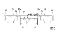
図5に示すように、図1に示す免震建物1の基礎部分(コア基礎部2A、外周基礎部2B)の地盤を掘削(一次掘削)する前に、コア基礎部2Aの側壁部に相当する位置に山留め壁21を例えば周知のSMW(Soil Mixing Wall)工法によって打設することにより施工する。つまり、外周基礎部2Bは、一次掘削によって形成される。そして、一次掘削後に、免震建物1の平面範囲内で適宜な位置に例えばアースドリル工法を用いて基礎杭2が打設される。
なお、一次掘削部(外周基礎部2B)の外周に形成される法面22は、地盤改良が行われ、山留めを用いない土型枠として機能する土留め部が形成されている。
Here, the concrete construction method of the seismic isolation building 1 is demonstrated based on drawing.
As shown in FIG. 5, before excavating (primary drilling) the ground of the foundation portion (
In addition, ground improvement is performed and the earth retaining part which functions as a soil formwork which does not use mountain retaining is formed in the
次に、外周基礎部2Bの盤下げ部2Baの掘削が行われる。盤下げ部2Baは、最もコア基礎部2A寄りに施工されている基礎杭2の杭頭2aを含む平面領域に設けられている。そして、この盤下げ部2Baには、全面にわたって仮設土間コンクリート5(図2参照)が打設される。具体的に仮設土間コンクリート5は、図3に示すように、仮設梁5Aの梁鉄筋5a及び連結鉄筋5bを組み、コンクリートを打設することにより施工される。なお、梁鉄筋5a及び連結鉄筋5bは、平面視で上述した盤下げ部2Baに位置する杭頭2aを囲うように配筋される。これにより、仮設土間コンクリート5は、コア基礎部2A側の端部5c(図2参照)が山留め壁21の上端21aに接続し、上述したように山留め壁21のバックアンカーとして機能する。
Next, excavation of board lowering part 2Ba of
そして、仮設土間コンクリート5の打設が完了した後、山留め壁21によって囲われた内側の地盤を掘削する二次掘削が行われ、外周基礎部2Bよりも深いコア基礎部2Aを形成する。
Then, after the placement of the
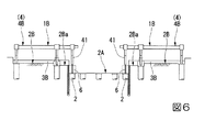
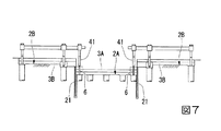
次に、図6に示すように、外周基礎部2Bにおいて、コア外周部1Bの外周部鉄骨4Bを建て込むとともに、鉄筋コンクリート造のマットスラブ3Bを打設する。なお、本実施の形態では、マットスラブ3B(コア基礎部2Aのマットスラブ3Aも同様)は上下2層に分けて順次打設している(図7参照)。つまり、図6において第1層目(下層)のマットスラブ3Bを施工し、図7において第2層目(上層)のマットスラブ3Bを施工する。
また、図5に示す二次掘削時においても、これと同時にコア外周部1Bの地上階の鉄骨4(外周部鉄骨4B)を建て込む施工を行うようにしてもよい。
Next, as shown in FIG. 6, in the outer
In addition, also at the time of secondary excavation shown in FIG. 5, construction may be carried out simultaneously with the construction of the steel frame 4 (outer
次いで、コア基礎部2Aにおける外周側で、基礎杭2の杭頭2a上に仮設鉄骨柱6を立設する(図4参照)。そして、予め下端に仮設鉄骨柱6が接続されている外周部鉄骨4Bの鉄骨柱41を建て込み、その鉄骨柱41を外周基礎部2B上に建て込んだ外周部鉄骨4Bに接続した後、マットスラブ3Aを打設する。つまり、図6及び図7に示すように、鉄骨柱41に接続されている仮設鉄骨柱6は、マットスラブ3Aの打設前に建て込んでおく。仮設鉄骨柱6は、その一部がマットスラブ3Aによって埋設されている。
Next, a temporary
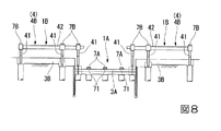
次に、図8に示すように、コア外周部1Bの地上部に設けられる外周部鉄骨4Bの鉄骨梁42上(平面視で鉄骨柱41の位置)に中間免震装置7Bを設置する。中間免震装置7Bは、その上側の鉄骨4との間に介在される。
Next, as shown in FIG. 8, the intermediate
さらに、コア部1Aのマットスラブ3A上にコア免震装置7Aを設置する。コア免震装置7Aは、プレキャストコンクリート製の免震基礎71を例えばアンカーボルト等の適宜な固定手段によってマットスラブ3A上に固定し、その免震基礎71上にコア免震装置7Aがセットされる。これらコア免震装置7A上にもコア部1Aの鉄骨4(コア部鉄骨4A)が設置されるので、コア免震装置7Aは、マットスラブ3Aとコア部鉄骨4A(図1参照)との間に介在されることになる。
Furthermore, the core
次に、図9に示すように、コア基礎部2Aに打設されるマットスラブ3Aと、外周基礎部2Bに打設されるマットスラブ3Bとを連結するための取付コンクリート3Cが打設される。取付コンクリート3Cは、コア基礎部2A内に位置する仮設鉄骨柱6の露出する上端部分と、その仮設鉄骨柱6上に接続される鉄骨柱41の下端部分を埋設するようにして、山留め壁21に沿って全周にわたって設けられる。
そして、これと同時に、中間免震装置7Bの上側の外周部鉄骨4Bを建て込む。
Next, as shown in FIG. 9, mounting concrete 3C for connecting the
Then, at the same time, the upper outer
続いて、図10に示すように、コア基礎部2Aにおいてコア部1Aのコア部鉄骨4Aの建て込みを行うとともに、このコア部1A及びコア外周部1Bにおいてさらに上階の鉄骨4を建て込む(図1参照)。
Subsequently, as shown in FIG. 10, the
次に、上述した免震建物及びその施工方法の作用について、図面に基づいて詳細に説明する。
図2に示すように、本実施の形態では、外周基礎部2Bの基礎底に打設された仮設土間コンクリート5をコア基礎部2Aに設けられる山留め壁21の上端21aに接続させることで、仮設土間コンクリート5が山留め壁21のバックアンカーとして機能し、山留め壁21が倒れる方向と反対側に引張り支持し、山留め壁21が倒れるのを防止することができる。
そのため、コア基礎部2Aの山留め壁21に一般的に設ける必要がある切り梁を省略することができ、コストの低減を図ることができる。
そして、切り梁の影響を受けずにコア部1Aの土工事、躯体工事を施工することができるので、そのコア基礎部2Aにおける切り梁の架け払しの作業が不要となり、工期の短縮を図ることができる。また、切り梁を省略できるので、掘削したコア基礎部2Aの基礎底において、免震基礎部の鉄筋、型枠を先行して施工することができる。
Next, the operation of the above-described seismic isolation building and its construction method will be described in detail based on the drawings.
As shown in FIG. 2, in the present embodiment, temporary temporary
Therefore, a cutting beam generally required to be provided on the retaining
And since earthwork and frame work of
また、コア基礎部2Aの基礎底における杭直上に仮設鉄骨柱6を設けることで、コア基礎部2Aにマットスラブ3Aのコンクリート打設する前の段階において、予め仮設鉄骨柱6を外周部鉄骨4Bの鉄骨柱41に接続することができるので、仮設鉄骨柱6上に本設の鉄骨柱脚を建て込む作業を早期に開始することができる。つまり、コア基礎部2Aにおけるマットスラブ3のコンクリート打設に伴う土工事と仮設鉄骨柱6上の鉄骨4の建込み作業とを同時に行うことができるので、工程の短縮を図ることができる。
In addition, by providing temporary
また、外周基礎部2Bにマットスラブ3Bを打設するとともに、コア外周部1Bの地上階の外周部鉄骨4Bに中間免震装置7Bを設ける構造となるので、その外周基礎部2Bの基礎掘削底上に直接、基礎梁や免震装置を設ける必要がなく、基礎掘削底の深さを小さく抑えることができ、掘削土量や躯体数量の低減を図ることができる。
Further, since the
しかも、外周基礎部2Bの基礎底の位置が浅い位置となるので、基礎掘削底を常水面以上の高さに変更することが可能となる。その場合には、地下水の排水が不要になり、排水設備を設けずにすむうえ、常水面よりも上部での作業となって地下水の無い状態で他の施工を行うことができるので、施工性が向上するという利点がある。
Moreover, since the position of the bottom of the outer
また、本実施の形態では、外周基礎部2Bの土留め部(法面22)が地盤改良により施工されており、外周基礎部2Bの法面22を一次掘削時に地盤改良し、土型枠として機能させることが可能となるので、山留め(親杭横矢板)や切り梁を省略することができ、コストの低減を図ることができる。
Further, in the present embodiment, the earth retaining portion (the slope surface 22) of the outer
また、本実施の形態では、コア部1Aのコア免震装置7Aの免震基礎71がプレキャストコンクリート製により形成されているので、コア基礎部2Aにおけるマットスラブ3Aの打設後において、コア免震装置7Aの免震基礎71の設置時間を短縮することができる。
また、免震基礎71がプレキャストコンクリート製であるので、現場で施工する場合に比べて施工精度の向上を図ることができる。
Further, in the present embodiment, since the
Further, since the
上述のように本実施の形態による免震建物及びその施工方法では、地下の免震基礎部を減らした構造とすることで、地下掘削の数量を少なく抑え、施工にかかるコストや工期を低減することができるうえ、施工品質を確保することができる。 As described above, in the seismic isolation building according to the present embodiment and the construction method thereof, the number of underground excavations is reduced by reducing the seismic isolation base portion in the underground, and the cost and construction period for construction are reduced. It is possible to secure the construction quality.
以上、本発明による免震建物及びその施工方法の実施の形態について説明したが、本発明は上記の実施の形態に限定されるものではなく、その趣旨を逸脱しない範囲で適宜変更可能である。
例えば、本実施の形態では、外周基礎部の土留め部(法面22)を地盤改良により施工しているが、これに限定されることはなく、一般的な土留壁を用いるものであってもよい。
As mentioned above, although embodiment of the seismic isolation building by this invention and its construction method were described, this invention is not limited to said embodiment, It can change suitably in the range which does not deviate from the meaning.
For example, in the present embodiment, although the earth retaining portion (the slope surface 22) of the outer peripheral foundation portion is constructed by ground improvement, the present invention is not limited to this, and a general earth retaining wall is used It is also good.
また、本実施の形態では、コア免震装置7Aの免震基礎71としてプレキャストコンクリート製により形成されたものを使用し、コア基礎部2Aのマットスラブ3A上に固定する構造としているが、プレキャストコンクリート製でなく、現場打設による施工による構造であってもかまわない。
Moreover, in this embodiment, although what was formed with a product made from precast concrete is used as the
なお、コア基礎部2A、外周基礎部2Bの深さは建物の形状、階高等の条件に応じて適宜設定することができる。
また、コア免震装置7A、中間免震装置7Bの数量、形状、仕様、設置位置などの構成についても、適宜設定することが可能である。
The depths of the
In addition, it is possible to appropriately set the configuration such as the number, the shape, the specification, and the installation position of the core
その他、本発明の趣旨を逸脱しない範囲で、上記した実施の形態における構成要素を周知の構成要素に置き換えることは適宜可能である。 In addition, without departing from the spirit of the present invention, it is possible to replace components in the above-described embodiment with known components as appropriate.
1 免震建物
1A コア部
1B コア外周部
2 基礎杭
2A コア基礎部
2B 外周基礎部
2Ba 盤下げ部
3、3A、3B マットスラブ
4 鉄骨
4A コア部鉄骨
4B 外周部鉄骨
5 仮設土間コンクリート
5A 仮設梁
6 仮設鉄骨柱
7A コア免震装置
7B 中間免震装置
21 山留め壁
22 法面
41 鉄骨柱
42 鉄骨梁
71 免震基礎
M1 基礎免震層
M2 中間免震層
DESCRIPTION OF SYMBOLS 1 seismically
Claims (4)
前記コア基礎部と前記外周基礎部とに打設された基礎杭と、
前記コア基礎部の土留め部として設けられる山留め壁と、
前記外周基礎部に打設されるマットスラブに埋設されることによって本設として機能するとともに、前記山留め壁の上端に接続され、連結鉄筋が埋設された仮設土間コンクリートと、
前記外周基礎部に設けられ、梁鉄筋が前記連結鉄筋を介して前記仮設土間コンクリートと一体で埋設された仮設梁と、
前記コア基礎部の基礎底に設けられ、前記コア基礎部に打設されるマットスラブに埋設されることによって本設として機能する仮設鉄骨柱と、
前記コア基礎部のマットスラブ上に設けられるコア免震装置と、
前記コア外周部の地上階の鉄骨に設けられる中間免震装置と、を備え、
前記梁鉄筋と前記連結鉄筋は、前記外周基礎部において前記仮設梁と前記山留め壁との間に打設されている前記基礎杭の杭頭を囲うように配筋されていることを特徴とする免震建物。 It is a seismically isolated building in which the core base supporting the core of the building has a base bottom deeper than the outer base supporting the core outer periphery of the building forming the outer periphery of the core,
Foundation piles placed on the core foundation and the outer periphery foundation;
A retaining wall provided as a retaining portion for the core foundation portion;
Temporary soil concrete that is connected to the upper end of the retaining wall and is embedded with a connecting rebar, while functioning as a main installation by being embedded in a mat slab cast in the outer peripheral foundation portion
A temporary beam which is provided in the outer peripheral foundation portion and in which a beam reinforcing member is embedded integrally with the temporary soil concrete via the connection reinforcing rod;
A temporary steel frame pillar which is provided on the foundation bottom of the core foundation portion and which is functioned as a permanent installation by being embedded in a mat slab driven on the core foundation portion;
A core seismic isolation device provided on a mat slab of the core base portion;
An intermediate seismic isolation device provided on a steel frame on the ground floor of the core outer peripheral portion ;
The beam reinforcing bars and the connection reinforcing bars are arranged so as to surround a pile head of the foundation pile which is disposed between the temporary beam and the retaining wall in the outer peripheral foundation portion. Seismic isolation building.
前記コア基礎部と前記外周基礎部とに基礎杭を打設する工程と、
前記コア基礎部の土留め部として山留め壁を設ける工程と、
コンクリートを打設することで連結鉄筋を埋設し、前記外周基礎部に打設されるマットスラブに埋設されることによって本設として機能する仮設土間コンクリートを設ける工程と、
前記外周基礎部においてコンクリートを打設することで梁鉄筋を前記連結鉄筋を介して前記仮設土間コンクリートと一体で埋設することにより仮設梁を設ける工程と、
該仮設土間コンクリートの一部を前記山留め壁の上端に接続する工程と、
前記コア基礎部の基礎底に仮設鉄骨柱を設け、該仮設鉄骨柱を前記コア基礎部に打設されるマットスラブに埋設することにより本設として機能させる工程と、
前記コア基礎部のマットスラブ上にコア免震装置を設ける工程と、
前記コア外周部の地上階の鉄骨に中間免震装置を設ける工程と、
を有し、
前記梁鉄筋と前記連結鉄筋は、前記外周基礎部において前記仮設梁と前記山留め壁との間に打設されている前記基礎杭の杭頭を囲うように配筋するようにしたことを特徴とする免震建物の施工方法。 A core foundation portion supporting a core portion of a building is a construction method of a seismic isolation building having a structure in which a foundation bottom is deeper than a peripheral foundation portion supporting a core outer peripheral portion of a building forming an outer peripheral portion of the core portion,
Placing a foundation pile on the core foundation portion and the outer periphery foundation portion;
Providing a retaining wall as a retaining portion of the core foundation portion;
Placing concrete reinforcing bars by placing concrete and placing temporary concrete between soils that functions as a main facility by being buried in a mat slab placed in the outer peripheral foundation portion;
A step of providing a temporary beam by embedding concrete in the outer peripheral foundation portion to embed a beam rebar integrally with the temporary soil concrete via the connection reinforcing bar;
Connecting a portion of the temporary soil concrete to the upper end of the retaining wall;
Providing a temporary steel frame column at the base bottom of the core base section, and embedding the temporary steel frame column in a mat slab driven in the core base section to function as a permanent installation;
Providing a core seismic isolation device on the mat slab of the core foundation;
Providing an intermediate seismic isolation device on the steel frame of the ground floor of the core outer peripheral portion;
I have a,
The beam reinforcing bars and the connection reinforcing bars are arranged so as to surround a pile head of the foundation pile which is installed between the temporary beam and the retaining wall in the outer peripheral foundation portion. Construction method of seismic isolation building.
Priority Applications (1)
| Application Number | Priority Date | Filing Date | Title |
|---|---|---|---|
| JP2014142552A JP6534026B2 (en) | 2014-07-10 | 2014-07-10 | Seismic isolation building and its construction method |
Applications Claiming Priority (1)
| Application Number | Priority Date | Filing Date | Title |
|---|---|---|---|
| JP2014142552A JP6534026B2 (en) | 2014-07-10 | 2014-07-10 | Seismic isolation building and its construction method |
Publications (2)
| Publication Number | Publication Date |
|---|---|
| JP2016017378A JP2016017378A (en) | 2016-02-01 |
| JP6534026B2 true JP6534026B2 (en) | 2019-06-26 |
Family
ID=55232802
Family Applications (1)
| Application Number | Title | Priority Date | Filing Date |
|---|---|---|---|
| JP2014142552A Active JP6534026B2 (en) | 2014-07-10 | 2014-07-10 | Seismic isolation building and its construction method |
Country Status (1)
| Country | Link |
|---|---|
| JP (1) | JP6534026B2 (en) |
Families Citing this family (1)
| Publication number | Priority date | Publication date | Assignee | Title |
|---|---|---|---|---|
| CN107604925B (en) * | 2016-04-08 | 2019-09-17 | 烟台三新新能源科技有限公司 | A kind of hypogee antidetonation suspension device |
Family Cites Families (3)
| Publication number | Priority date | Publication date | Assignee | Title |
|---|---|---|---|---|
| JP3109038B2 (en) * | 1992-08-04 | 2000-11-13 | 清水建設株式会社 | Underground skeleton structure and construction method |
| JP4013182B2 (en) * | 1999-04-19 | 2007-11-28 | 株式会社竹中工務店 | Self-supporting mountain retaining wall method and self-supporting mountain retaining wall |
| JP4092624B2 (en) * | 2002-05-15 | 2008-05-28 | 清水建設株式会社 | Seismic isolation structure of building |
-
2014
- 2014-07-10 JP JP2014142552A patent/JP6534026B2/en active Active
Also Published As
| Publication number | Publication date |
|---|---|
| JP2016017378A (en) | 2016-02-01 |
Similar Documents
| Publication | Publication Date | Title |
|---|---|---|
| KR101341679B1 (en) | Device for constructing an underground structure and method thereof | |
| KR100967497B1 (en) | Method for constructing an underground structure | |
| JP6543176B2 (en) | Building method | |
| JP5937488B2 (en) | Temporary support method for foundation | |
| JP2023011057A (en) | Foundation structure and foundation construction method | |
| JP2017214722A (en) | Construction method of base structure, and base structure | |
| KR20190022132A (en) | Top-down method using precast-concrete colum | |
| KR101324231B1 (en) | Soil cement wall structure and method for constructing thereof | |
| KR20060092552A (en) | Construction method of unsupported downward frame using cast-in-place pile | |
| JP5976373B2 (en) | Pile foundation reinforcement structure and reinforcement method | |
| JP2012112121A (en) | Excavation method of ground under spread foundation and base-isolating method of existing building | |
| JP6252860B2 (en) | Construction method of seismic isolation building | |
| JP7007691B1 (en) | Casting method for spring spacers, reinforcing bar cages and underground piles | |
| KR100625115B1 (en) | Reinforced concrete reinforcement underground structure construction method using temporary auxiliary column | |
| KR20130021952A (en) | Underground structure having slab beam with enhanced bearing power against earth pressure and construction methods of the same | |
| KR101222348B1 (en) | The Supporting Structure and Pressing device of Underground Structure | |
| JP5367452B2 (en) | Underground wall construction method and underground wall body | |
| JP6534026B2 (en) | Seismic isolation building and its construction method | |
| JP6326294B2 (en) | Construction method of earth retaining structure | |
| JP7182485B2 (en) | building construction method | |
| JP4228308B2 (en) | Reinforcement method for existing floors and seismic isolation method for existing buildings | |
| KR20130021949A (en) | Reinforcement structure for wall of underground structure and construction method of underground structure using the same | |
| KR100967496B1 (en) | Device for constructing an underground structure | |
| JP6543177B2 (en) | Building method | |
| JP2016079651A (en) | Support structure |
Legal Events
| Date | Code | Title | Description |
|---|---|---|---|
| A621 | Written request for application examination |
Free format text: JAPANESE INTERMEDIATE CODE: A621 Effective date: 20170517 |
|
| A977 | Report on retrieval |
Free format text: JAPANESE INTERMEDIATE CODE: A971007 Effective date: 20180308 |
|
| A131 | Notification of reasons for refusal |
Free format text: JAPANESE INTERMEDIATE CODE: A131 Effective date: 20180320 |
|
| A521 | Written amendment |
Free format text: JAPANESE INTERMEDIATE CODE: A523 Effective date: 20180510 |
|
| RD03 | Notification of appointment of power of attorney |
Free format text: JAPANESE INTERMEDIATE CODE: A7423 Effective date: 20181005 |
|
| A131 | Notification of reasons for refusal |
Free format text: JAPANESE INTERMEDIATE CODE: A131 Effective date: 20181016 |
|
| A521 | Written amendment |
Free format text: JAPANESE INTERMEDIATE CODE: A523 Effective date: 20181211 |
|
| TRDD | Decision of grant or rejection written | ||
| A01 | Written decision to grant a patent or to grant a registration (utility model) |
Free format text: JAPANESE INTERMEDIATE CODE: A01 Effective date: 20190423 |
|
| A61 | First payment of annual fees (during grant procedure) |
Free format text: JAPANESE INTERMEDIATE CODE: A61 Effective date: 20190515 |
|
| R150 | Certificate of patent or registration of utility model |
Ref document number: 6534026 Country of ref document: JP Free format text: JAPANESE INTERMEDIATE CODE: R150 |


