JP4273739B2 - RESIN COMPOSITION FOR DIELECTRIC HEAT-ADJUSTING, HOT-MELT ADHESIVE, ADHESIVE METHOD FOR ADHESIVE MATERIAL, ADHESIVE RESIN COMPOSITION AND ADHESIVE COMPOSITE USED AS A HOT-MELT ADHESIVE ADHESIVE - Google Patents
RESIN COMPOSITION FOR DIELECTRIC HEAT-ADJUSTING, HOT-MELT ADHESIVE, ADHESIVE METHOD FOR ADHESIVE MATERIAL, ADHESIVE RESIN COMPOSITION AND ADHESIVE COMPOSITE USED AS A HOT-MELT ADHESIVE ADHESIVE Download PDFInfo
- Publication number
- JP4273739B2 JP4273739B2 JP2002302186A JP2002302186A JP4273739B2 JP 4273739 B2 JP4273739 B2 JP 4273739B2 JP 2002302186 A JP2002302186 A JP 2002302186A JP 2002302186 A JP2002302186 A JP 2002302186A JP 4273739 B2 JP4273739 B2 JP 4273739B2
- Authority
- JP
- Japan
- Prior art keywords
- adhesive
- resin composition
- present
- dielectric
- resin
- Prior art date
- Legal status (The legal status is an assumption and is not a legal conclusion. Google has not performed a legal analysis and makes no representation as to the accuracy of the status listed.)
- Expired - Fee Related
Links
Images

Classifications
-
- B—PERFORMING OPERATIONS; TRANSPORTING
- B29—WORKING OF PLASTICS; WORKING OF SUBSTANCES IN A PLASTIC STATE IN GENERAL
- B29C—SHAPING OR JOINING OF PLASTICS; SHAPING OF MATERIAL IN A PLASTIC STATE, NOT OTHERWISE PROVIDED FOR; AFTER-TREATMENT OF THE SHAPED PRODUCTS, e.g. REPAIRING
- B29C66/00—General aspects of processes or apparatus for joining preformed parts
- B29C66/70—General aspects of processes or apparatus for joining preformed parts characterised by the composition, physical properties or the structure of the material of the parts to be joined; Joining with non-plastics material
- B29C66/71—General aspects of processes or apparatus for joining preformed parts characterised by the composition, physical properties or the structure of the material of the parts to be joined; Joining with non-plastics material characterised by the composition of the plastics material of the parts to be joined
Description
【0001】
【発明の属する技術分野】
本発明は、誘電加熱接着用樹脂組成物に関する。さらに詳しくは、本発明は、加熱炉を使用することなく短時間高周波電圧を印加することにより加熱溶融させることができ、ガラス、セラミックス、金属、樹脂、よりなる群から選ばれた同種または異種材料同士の接着に用いた場合に比較的高温での接着強度に優れた誘電加熱接着用樹脂組成物に関する。
【0002】
また、本発明は、本発明の誘電加熱接着用樹脂組成物を含有するホットメルト接着剤にも関する。さらに、本発明は、本発明の誘電加熱接着用樹脂組成物を用いた被接着材の接着方法に関する。
【0003】
そして、本発明は、本発明のホットメルト接着剤の被接着材として用いられる被接着用樹脂組成物に関する。
【0004】
また、本発明は、本発明のホットメルト接着剤と被接着材とを備える接着複合体に関する。さらに、本発明は、本発明の接着複合体の解体方法に関する。
【0005】
【従来の技術】
近年、接着剤の機能の進歩は目覚しく、電気、機械、土木、建築、木材、紙、繊維、化学などの多くの分野で接着剤が利用されている。また、接着剤の機能の高度化に伴い、従来は副資材的な使われ方をしてきた接着剤が、最近は重要な構造部分の主用資材の接着にも用いられるようになりつつある。たとえば、自動車のブレーキライニング間の接着、航空機の軽量強化策のハニカム構造の接着など、信頼性を必要とする個所にも接着剤が多く使われている。
【0006】
従来から汎用的に使用されてきたネジ、釘、溶接などの接着技術に代えて接着剤を利用すると、製造工程を簡略化することができ、大幅なコストの削減を実現できる場合が多く、また、接着剤を利用すると製品を軽量化することができる。そして、この接着剤による軽量化が、自動車、鉄道車両、航空機などに応用されると、動力エネルギーの省力化に間接的に寄与することとなり、さらに間接的に地球環境問題の原因となり得る二酸化炭素の排出量削減に寄与することとなる。そのため、各産業分野で接着剤の重要性はますます高まりつつある。
【0007】
上記のように、自動車、鉄道用車両、航空機の製造、あるいは、土木や建築などの分野で用いられるような、大きなガラス、セラミックス、金属、樹脂、よりなる群から選ばれた同種または異種材料同士を接着する場合、従来は、接着性および/またはその結合の耐久性の改善のために、接着剤を塗布する前に被接着材の表面にプライマーを塗布し、当該プライマーの乾燥および/または硬化後に、当該プライマーの塗膜の表面に接着剤を塗布し、当該接着剤を乾燥および/または硬化させて被接着材同士を接着させることが多かった。
【0008】
しかし、プライマーを用いて被接着材の化学的前処理を行なった場合には、プライマーおよび/または接着剤の含有する溶剤の乾燥や、プライマーおよび/または接着剤の硬化反応に長時間がかかるという問題があり、また溶剤の使用による作業環境および地球環境への悪影響という問題があった。
【0009】
そこで、上記の問題を解決するために、最近では、ホットメルト接着剤が工業的に広く利用されてきている。ホットメルト接着剤は、溶剤をほとんど含有しないか、あるいは溶剤を全く含有しないため、作業環境および地球環境に悪影響を与えることが少なく、引火の危険性が低く、常温で固形のため取扱いが簡単であるなどの特徴を有し、さらに溶融接着後放置するとすぐに固化するので自動化による高速大量加工処理に適した接着剤ということができる。
【0010】
しかし、一般的なホットメルト接着剤には、高温下での接着強度が低く要求の性能が得られない場合が多いという難点がある。また、高温タイプのホットメルト接着剤を使用する場合、当該接着剤の融点が高いため大きな加熱炉が必要であるため製造コストがその分高くならざるを得ない。また、ホットメルト接着剤を使用する場合には、加熱工程と冷却工程のサイクルが必要であり、工業化にあたっては大きな障害があり、実用化には困難が伴わざるを得ない。
【0011】
そこで、上記のようなホットメルト接着剤の長所を有し、かつ上記のような短所を克服した接着剤を得ようとして、現在各方面でホットメルト接着剤の開発に多くの努力が払われている。本発明における誘電加熱接着用樹脂組成物を含有する接着剤は、ホットメルト接着剤の一種であり、当該接着剤を被接着材間に介在させた状態で高周波電圧を印加することによって加熱溶融され、その後冷却されて固化することにより被接着材同士を接着させる機能を有する。本発明の誘電加熱接着用樹脂組成物を含有する接着剤を用いる場合は、大きな加熱炉を有するアプリケーターなどを必要としないため、従来のホットメルト接着剤を用いる場合よりも、さらに被接着材同士の接着工程を簡便なものにすることができる。そのため、本発明の誘電加熱接着用樹脂組成物を含有する接着剤を用いることにより生産性の大幅な向上が可能となる。
【0012】
ここで、これまで高周波発熱は、分子の極性化に基づく分子摩擦による発熱によるものと考えられており、一般に熱可塑性樹脂の高周波電圧の印加による発熱効率は、誘電率(ε)、誘電正接(tanδ)およびこれらの積である誘電損失係数{(ε)×(tanδ)}が大きいほど優れていると考えられている。そして、熱可塑性樹脂の中でも、ポリエチレン系樹脂やポリプロピレン系樹脂などの炭化水素結合を主体とするポリオレフィン系樹脂は、無極性であるので誘電率(ε)および誘電正接(tanδ)が小さく高周波加熱には適さないと考えられている。
【0013】
反面、ポリオレフィン系樹脂は、靭性、耐衝撃性、柔軟性、加工性、透明性、耐酸性、耐アルカリ性、水に対する低透過性、熱安定性、電気的絶縁性などに優れており、融点以上で高い粘性を示すため、接着剤用のバインダ樹脂として適した性質を備えているといえる。また、ポリオレフィン系樹脂は、世界で最も大量に生産されている樹脂であるため、入手が容易かつ低価格であるという面でも優れている。そのため誘電加熱可能なホットメルト接着剤のバインダ樹脂としてポリオレフィン系樹脂を用いることを可能にする技術の開発が強く望まれている。
【0014】
実際、ポリオレフィン系樹脂の有する優れた特性を生かしながら上記の問題点を克服するために、ポリオレフィン系樹脂にポリ塩化ビニル樹脂のような極性の高い樹脂を混合する技術や、熱可塑性樹脂に誘電損失係数の大きい無機物質を配合する技術(たとえば、特許文献1参照。)や、熱可塑性樹脂に強誘電体を配合する技術(たとえば、特許文献2参照。)も提案されているが、いずれの技術も発熱不足のため加熱に時間が掛かり過ぎ実用的ではない。また、ポリ塩化ビニル樹脂については、ポリオレフィン樹脂よりも比重が重いため施工時に取扱いが難しく、焼却処理することによりダイオキシンをはじめとする人体や地球環境に悪影響を与える物質を生成する可能性があるという問題がある。
【0015】
また、高周波電圧を印加する誘電加熱では発熱量が全く不足することから、強磁性体を配合して高周波コイルによる導電体の誘導加熱を使用した電磁誘導加熱を利用することもなされている(たとえば、特許文献3参照。)が、このような複合体の誘導加熱は効率が低いため接着剤の熱容量に比較して被接着材の熱容量が不足する場合、接着剤を接着に必要な温度まで上げるには長時間を要するため生産性が低く、現在のところ実用化できる段階にはない。
【0016】
さらに、ポリオレフィン系樹脂などの無極性樹脂のフィルムにフェライトなどの電磁波吸収体を配合あるいは塗布したフィルムが開示されている(たとえば、特許文献4参照。)。また、熱可塑性樹脂100質量部に、無機他孔質粉末2〜20質量部に液状の極性物質3〜30質量部を吸着させた高周波またはマイクロ波増感剤を加えた熱可塑性樹脂組成物が開示されている(たとえば、特許文献5参照。)。しかし、これらの技術を用いても、ポリオレフィン系樹脂を十分短い時間で加熱溶融することができ、十分に強い接着性を有する誘電加熱接着用樹脂組成物として用いることは未だにできないのが現状である。
【0017】
そして、超高分子量ポリエチレンに、酸化亜鉛、ベントナイト、およびアルカリ金属もしくはアルカリ土類金属のアルミノケイ酸塩などの無線周波増感剤と、無線周波感度の向上に適する物質とを加える技術が開示されている(たとえば、特許文献6参照。)。また、熱可塑性ポリマーに、N−エチルトルエンスルホンアミドを4〜10質量%配合した組成物からなる無線周波エネルギー増感剤を加える技術が開示されている(たとえば、特許文献7参照。)。さらに、ポリオレフィン樹脂100質量部に、結晶水を有する無機粉末を20〜200質量部配合する技術が開示されている(たとえば、特許文献8参照。)。また、Q.X.Nguyen, R. Gauvin, Y. Belanger; ANTEC ’91, p2245−2247に開示されているように、超高分子量ポリエチレンにアルミノケイ酸ナトリウムを加える技術は一般によく知られている。また、市販のマイクロ波増感剤としては、STRUKTOL社(米国)製、FREQUON(商品名)などがよく知られている。しかし、これらの技術を用いても、やはりポリオレフィン系樹脂を十分に短い時間で加熱溶融することができ、十分に強い接着性を有する誘電加熱接着用樹脂組成物として用いることは未だにできないのが現状である。
【0018】
さらに、ポリオレフィン系樹脂のうちエチレン−酢酸ビニル共重合体やエチレン−メチルアクリレート共重合体などの極性基を有するエチレン系共重合体は高温融着が可能であることはよく知られている。そして、プロピレン−α−オレフィンブロック共重合体に、ポリアミド、ビニル重合体、ポリエステルまたはポリウレタンを混合する技術が開示されている(たとえば、特許文献9参照。)。
【0019】
また、プロピレン系重合体と、エチレンおよび不飽和カルボン酸および/または不飽和カルボン酸誘導体からなるエチレン系共重合体とを配合する樹脂組成物が開示されている(たとえば、特許文献10参照。)。しかし、これらの共重合体は、接着性および加熱に要する時間の面でも不十分なものであるのが現状である。
【0020】
ここで、上記のように、被接着材の接着工程の時間短縮のために、ホットメルト接着剤を用いて急激な加熱を行なう接着方法を選ぶと、ホットメルト接着剤のみならず被接着材も軟化あるいは溶融し、その被接着材の再硬化に時間がかかるため、実用化に問題があった。特に、ホットメルト接着剤の熱容量に比較して被接着体の熱容量が不足する場合には、ホットメルト接着剤を接着に必要な温度まで上げるには長時間を要するため、生産性が低くなり実用的でない。
【0021】
そのため、上記のようにホットメルト接着剤の加熱速度が加速化するに伴い、一方では被接着材に対しても高速な加熱や固化に耐える材質の開発の要求が高まってきた。そのため、近年、未だ実例は少ないが、幾つかの企業等がこのようなホットメルト接着剤用の被接着材の開発に取組み始めている。
【0022】
たとえば、ドアトリムなどの基材に対して、ホットメルト接着剤により高い接着性を持って貼着されるポリエチレンテレフタレートからなるパッキング樹脂層を備える内装材についての技術が開示されている(たとえば、特許文献11参照。)。しかし、この技術は、一般的なホットメルト接着剤との接着性を向上させることのみを目的としており、この文献には、高周波誘電加熱可能なホットメルト接着剤についての記載は無い。
【0023】
また、これまで、自動車業界、家電業界を始めとして、従来公知の接着剤を用いて組立てられた各種部品の廃棄物は、接着部分の剥離が難しいため、粉砕した上で廃棄されてきた。このため、あらゆる産業においてリサイクルの促進が求められているにも関わらず、各種部品の廃棄物を構成する各種材質を分別して、再使用や再生ができなかった。
【0024】
このような問題を克服するため、一部の部品においては、ホットメルト接着剤の使用が試みられ、ホットメルト接着剤を加熱溶融して被接着材を剥離することにより、リサイクルの促進に一応の成果を挙げてきた。しかし、従来公知のホットメルト接着剤を使用して組立てられた部品においては、組立てられた部品全体を加熱炉の中で高温処理することが必要であるため、大きな加熱炉が必要なことによるコストの増加や、加熱によるリサイクル部品の材質の劣化などのため、再利用を促進する効果にも一定の限界があった。
【0025】
また、従来公知のホットメルト接着剤により組立てられた部品を解体するには、加熱工程と冷却工程のサイクルが必要であり、接着部分以外の部位まで加熱しなければならず加熱効率も悪いことから、工業化に大きな障害となる。そのため、従来公知のホットメルト接着剤により組立てられた部品の解体方法は、本格的には実用化されてこなかった。
【0026】
そこで、このような問題を克服するために、高周波誘導で発熱する発熱体を含有する熱可塑性樹脂組成物を含有するホットメルト接着剤で接着された部品を誘導加熱して被接着材を剥離させる解体方法が開発されてきている(たとえば、特許文献12参照。)。しかし、発熱体としてあらかじめ熱可塑性樹脂組成物に金属を挿入しておく必要があり、加熱効率も十分であるとは言えないため、実用化に至っていないのが現状である。
【0027】
【特許文献1】
特開昭52−68273号公報
【0028】
【特許文献2】
特開昭54−161645号公報
【0029】
【特許文献3】
特開昭62−132983号公報
【0030】
【特許文献4】
特開平6−182876号公報
【0031】
【特許文献5】
特開平6−228368号公報
【0032】
【特許文献6】
特公平5−42982号公報
【0033】
【特許文献7】
特開平2−182419号公報
【0034】
【特許文献8】
特開平2−129243号公報
【0035】
【特許文献9】
特公平8−193150号公報
【0036】
【特許文献10】
特開平10−273568号公報
【0037】
【特許文献11】
特開2001−58382号公報
【0038】
【特許文献12】
特開2002−144341号公報
【0039】
【発明が解決しようとする課題】
上記の現状に基づき、本発明の課題は、非常に短時間の高周波電圧の印加により加熱溶融させることができ、比較的高温でも優れた接着強度を有する誘電加熱接着用樹脂組成物を提供することである。
【0040】
また、本発明の他の課題は、非常に短時間の高周波電圧の印加により加熱溶融させることができ、比較的高温でも優れた接着強度を有するホットメルト接着剤を提供することである。
【0041】
そして、本発明のまた別の課題は、非常に短時間の高周波電圧の印加により優れた接着強度を実現することができる被接着材同士の接着方法を提供することである。
【0042】
また、本発明のさらに他の課題は、ホットメルト接着剤による接着の際に、ホットメルト接着剤の加熱により溶融あるいは軟化し難く、かつ短時間に再硬化して優れた接着性を示す、ホットメルト接着剤の被接着材として用いられる被接着用樹脂組成物を提供することである。
【0043】
さらに、本発明のさらに別の課題は、加熱炉を使用することなく高周波電圧の印加により短時間に解体ができ、被接着体の材質が良好に再使用できる、高周波電圧を印加することにより解体可能な、接着複合体を提供することである。
【0044】
そして、本発明のもう一つの課題は、上記の接着複合体の接着部分のみを効率的に加熱することにより、解体時におけるエネルギー、時間および労力を省力化することができる、上記の接着複合体の解体方法を提供することである。
【0045】
【課題を解決するための手段】
本発明者らは、上記の誘電加熱接着用樹脂組成物、ホットメルト接着剤および被接着材同士の接着方法を提供するには、ポリオレフィン系樹脂に導電物質を含有させて、ポリオレフィン系樹脂の誘電正接を高めればよいとの着想を得、さまざまな導電物質を用いて鋭意検討を重ねた。そして、検討の末に、体積抵抗率が10-2Ω・cm以下である導電物質を含有することにより、ポリオレフィン系樹脂の誘電正接を高めることができることを見出し、本発明の誘電加熱接着用樹脂組成物、ホットメルト接着剤および被接着材同士の接着方法を完成させた。
【0046】
すなわち、本発明の誘電加熱接着用樹脂組成物は、融点が80〜200℃の範囲にあるポリオレフィン系樹脂と、体積抵抗率が10-2Ω・cm以下である導電物質とを含有し、当該導電物質の含有量は1〜30容量%の範囲にあり、40MHzの周波数において23℃条件下の誘電正接が0.03以上であることを特徴とする。
【0047】
ここで、この導電物質の含有量は5〜25容量%の範囲にあればさらに望ましい。また、本発明の誘電加熱接着用樹脂組成物は、40MHzの周波数において23℃条件下の誘電正接が0.1以上であることが好ましい。
【0048】
また、本発明の誘電加熱接着用樹脂組成物においては、この導電物質の体積抵抗率は10-4Ω・cm以下であることが好ましい。さらに、この導電物質は、鉄、銅、銀、鉄を主成分とする合金、銅を主成分とする合金、銀を主成分とする合金、炭素、炭素を主成分とする無機化合物よりなる群から選ばれる一種または二種以上の材質を含有することが望ましい。
【0049】
そして、この導電物質は、粉末状、粒状、顆粒状、針状、繊維状、鱗片状、よりなる群から選ばれる一種または二種以上の形状を有していることが好ましい。このとき、この導電物質は、平均粒径が10〜500μmの範囲にあることが望ましい。また、この導電物質は、誘電加熱接着用樹脂組成物に均一に分散した状態で含有されていることが推奨される。
【0050】
また、この導電物質は、網状、薄膜状、紐状、棒状、よりなる群から選ばれる一種または二種以上の形状を有していてもよい。このとき、本発明の誘電加熱接着用樹脂組成物は、この導電物質を含有する層と、ポリオレフィン系樹脂を含有する樹脂組成物を含有する層とを積層した構造を有していてもよい。ここで、本発明の誘電加熱接着用樹脂組成物は、薄膜状に成形されていることが好ましい。
【0051】
さらに、本発明の誘電加熱接着用樹脂組成物は、高周波電圧を印加することにより加熱溶融し、その後冷却することにより凝固して接着性を発揮することが好ましい。そして、この場合本発明の誘電加熱接着用樹脂組成物は、周波数が1〜5000MHzの範囲にあり、高周波出力0.1〜100kWの範囲にある高周波電圧を1〜1000秒間の範囲で印加することにより加熱溶融することが望ましい。
【0052】
また、本発明のホットメルト接着剤は、前記誘電加熱接着用樹脂組成物を含有することを特徴とする。
【0053】
そして、本発明の被接着材の接着方法は、被接着材の間に挟まれた前記ホットメルト接着剤に対して、周波数が1〜5000MHzの範囲にあり、高周波出力0.1〜100kWの範囲にある高周波電圧を1〜1000秒間の範囲で印加することにより加熱溶融する工程を含むことを特徴とする。
【0054】
また、本発明者らは、上記の課題を解決するには、融点が高いため加熱により溶融あるいは軟化し難く、かつ結晶化発熱ピーク温度が高いため短時間で再硬化しやすい樹脂組成物を、ホットメルト被接着剤の被接着材として用いればよいとの着想を得、さまざまな種類の樹脂組成物を用いて鋭意検討を重ねた。そして、検討の末に、本発明者らは、結晶性熱可塑性樹脂を含有し、かつ23℃における曲げ強度が100〜400MPaの範囲にある被接着用樹脂組成物であり、かつこの結晶性熱可塑性樹脂は、融点が150〜350℃の範囲にあり、この融点と、降温速度が10℃/分の条件における溶融状態からの降温過程における結晶化発熱ピーク温度と、の差が0〜70℃の範囲にある結晶性熱可塑性樹脂を用いた被接着材は、加熱によって溶融あるいは軟化し難く、かつ再硬化しやすい被接着材となるため、ホットメルト接着剤の被接着材として好適に用いることができることを見出し、本発明の被接着用樹脂組成物を完成させた。
【0055】
すなわち、本発明の被接着用樹脂組成物は、ホットメルト接着剤の被接着材として用いられる被接着用樹脂組成物であって、この被接着用樹脂組成物は、結晶性熱可塑性樹脂を含有し、かつ23℃における曲げ強度が100〜400MPaの範囲にある被接着用樹脂組成物であり、かつこの結晶性熱可塑性樹脂は、融点が150〜350℃の範囲にあり、この融点と、降温速度が10℃/分の条件における溶融状態からの降温過程における結晶化発熱ピーク温度と、の差が0〜70℃の範囲にある結晶性熱可塑性樹脂である、被接着用樹脂組成物である。
【0056】
ここで、本発明の被接着用樹脂組成物は、40MHzの周波数における23℃条件下の誘電正接が0〜0.1の範囲にあることが好ましい。
【0057】
また、この結晶性熱可塑性樹脂は、ポリエステル系樹脂を含有することが好ましい。さらに、この結晶性熱可塑性樹脂は、ポリエステル系樹脂と、ポリオレフィン系樹脂とを含有することがより望ましい。
【0058】
そして、本発明の被接着用樹脂組成物は、脂肪酸金属塩、安息香酸塩、ソルビトール系化合物、タルク、クレイからなる群より選ばれる1種以上の結晶核剤を含有することが推奨される。また、本発明の被接着用樹脂組成物は、繊維状強化材、カップリング剤、ミネラル強化材からなる群より選ばれる1種以上の強化剤を含有することが好ましい。
【0059】
また、本発明の被接着用樹脂組成物は、高周波誘電加熱により融解するホットメルト接着剤との接着強度が1.0〜10MPaの範囲にあることが望ましい。ここで、このホットメルト接着剤は、融点が80〜200℃の範囲にあるポリオレフィン系樹脂と、体積抵抗率が10-2Ω・cm以下である導電物質とを含有し、40MHzの周波数における23℃条件下の誘電正接が0.03以上であるホットメルト接着剤であり、このホットメルト接着剤中のこの導電物質の含有量は1〜30容量%の範囲にあることが推奨される。
【0060】
また、本発明者らは、上記の接着複合体および接着複合体の解体方法を提供するには、誘電加熱接着用樹脂組成物を含有し、高周波電圧を印加することにより加熱溶融するホットメルト接着剤と、このホットメルト接着剤により接合部において接着された被接着材とを備えた接着複合体を用いればよいとの着想を得、さまざまな種類のホットメルト接着剤および被接着材からなる接着複合体を試作して鋭意検討を重ねた。そして、検討の末に、本発明者らは、融点が60〜200℃の範囲にあるポリオレフィン系樹脂と、体積抵抗率が10-2Ω・cm以下である導電物質とを含有し、40MHzの周波数における23℃条件下の誘電正接が0.03以上であり、1〜30容量%の導電物質を含有する誘電加熱接着用樹脂組成物を含むホットメルト接着剤を用いることにより、加熱炉を使用することなく高周波電圧の印加により短時間に解体ができ、被接着体の材質が良好に再使用できる、高周波電圧を印加することにより解体可能な、接着複合体を得ることができることを見出し、本発明の接着複合体および接着複合体の解体方法を完成させた。
【0061】
すなわち、本発明の接着複合体は、ホットメルト接着剤と、このホットメルト接着剤により接合部において接着された被接着材とを備えた接着複合体であって、このホットメルト接着剤は、誘電加熱接着用樹脂組成物を含有し、高周波電圧を印加することにより加熱溶融するホットメルト接着剤であり、この誘電加熱接着用樹脂組成物は、融点が60〜200℃の範囲にあるポリオレフィン系樹脂と、体積抵抗率が10-2Ω・cm以下である導電物質とを含有し、40MHzの周波数における23℃条件下の誘電正接が0.03以上である、誘電加熱接着用樹脂組成物であり、この導電物質の前記誘電加熱接着用樹脂組成物中の含有量は1〜30容量%の範囲にある、高周波電圧を印加することにより解体可能な、接着複合体である。
【0062】
ここで、この誘電加熱接着用樹脂組成物の40MHzの周波数における23℃条件下の誘電正接が0.1以上であることが好ましい。
【0063】
また、この導電物質の体積抵抗率は10-4Ω・cm以下であることが望ましい。さらに、この導電物質は、鉄、銅、銀、鉄を主成分とする合金、銅を主成分とする合金、銀を主成分とする合金、炭素、炭素を主成分とする無機化合物よりなる群から選ばれる一種または二種以上の材質を含有することが推奨される。
【0064】
そして、この導電物質は、粉末状、粒状、顆粒状、針状、繊維状、鱗片状、よりなる群から選ばれる一種または二種以上の形状を有し、かつこの誘電加熱接着用樹脂組成物に均一に分散した状態で含有されていることが好ましい。
【0065】
また、この被接着材の40MHzの周波数における23℃条件下の誘電正接は0〜0.1の範囲であることが望ましい。さらに、この誘電加熱接着用樹脂組成物の40MHzの周波数における誘電正接は、この被接着材の40MHzの周波数における誘電正接の2倍よりも大きいことが推奨される。
【0066】
そして、本発明の接着複合体の解体方法は、上記接合部に対して上記高周波電圧を印加することにより、上記ホットメルト接着剤を加熱溶融させるステップと、上記被接着材を前記接合部において剥離するステップとを備える、上記の接着複合体の解体方法である。
【0067】
ここで、この加熱溶融させるステップは、この接合部に対して、周波数が1〜5000MHzの範囲にあり、高周波出力0.1〜100kWの範囲にあるこの高周波電圧を、1〜1000秒間の範囲で印加するステップを含むことが好ましい。
【0068】
【発明の実施の形態】
以下、実施の形態を示して本発明をより詳細に説明する。
【0069】
<誘電加熱接着用樹脂組成物>
最初に、誘電加熱接着用樹脂組成物について説明することとする。
【0070】
ここで、本明細書において、誘電加熱接着用樹脂組成物とは、高周波電圧を印加することにより加熱溶融し、その後冷却することにより凝固して、被接着材同士を接着させる性質を有するホットメルト接着剤のバインダとして好適に使用し得る樹脂組成物を指すものとする。
【0071】
次に、本発明の誘電加熱接着用樹脂組成物の誘電正接(tanδ)について説明することとする。
【0072】
ここで、誘電正接(tanδ)とは、複素誘電率の損失係数(tanδ)を指し、一般に熱可塑性樹脂の高周波電圧の印加による発熱効率は、誘電率(ε)、誘電正接(tanδ)およびこれらの積である誘電損失係数{(ε)×(tanδ)}が大きいほど優れていると考えられている。
【0073】
そして、本発明の誘電加熱接着用樹脂組成物の40MHzの周波数における23℃条件下の誘電正接(tanδ)(以下、単に本発明の誘電加熱接着用樹脂組成物の(tanδ)と呼称する)は0.03以上である必要があり、0.1以上であれば好ましい。本発明の誘電加熱接着用樹脂組成物の誘電正接(tanδ)が0.03未満の場合には、発熱が乏しくホットメルト接着剤が溶融しないか、長時間の加熱が必要であるという問題が生じるためである。
【0074】
次に、本発明の誘電加熱接着用樹脂組成物に用いられるポリオレフィン系樹脂(以下、単に本発明に用いるポリオレフィン系樹脂と呼称する)について説明することとする。
【0075】
ここで、一般にオレフィンとは、1個の炭素間二重結合を有し反応性の高い不飽和炭化水素のことを示し、エチレンやプロピレンなどが代表例である。また、一般にポリオレフィン系樹脂とは、オレフィン単量体の重合反応により製造される樹脂を示し、ポリエチレンやポリプロピレンなどが代表例である。
【0076】
そして、本発明に用いるポリオレフィン系樹脂としては、要求される特性を満たす限り特に限定されるものではなく、従来公知のポリオレフィン系樹脂およびジエン系樹脂を使用可能である。ポリオレフィン系樹脂の具体例としては、ポリエチレン系樹脂、ポリプロピレン系樹脂、ポリエチレン共重合系樹脂、ポリプロピレン共重合系樹脂、エチレン−プロピレン共重合系樹脂、エチレン−αオレフィン共重合系樹脂などが挙げられる。
【0077】
ここで、本発明に用いるポリオレフィン系樹脂としては、前述のポリオレフィン系樹脂の一種または二種以上を同時に混合して使用可能である。また、ジエン系樹脂はポリオレフィン系樹脂に含まれないのではないかという疑義も生じ得るが、本明細書においてポリオレフィン系樹脂と称する際には、説明の都合上、ジエン系樹脂を含むものとする。
【0078】
また、本発明に用いるポリオレフィン系樹脂は、酢酸ビニル、メタクリル酸、アクリル酸、メタクリル酸メチル、アクリル酸エチル、アクリル酸ブチル、メタクリル酸塩などを、ポリオレフィン系樹脂全体の3〜50モル%の範囲で共重合成分として含有することが好ましい。単量体成分の含有量が3モル%未満の場合には接着性が低下する傾向があり、単量体成分の含有量が50モル%を超える場合にはポリオレフィン系樹脂の有する耐熱性が失われてしまう場合がある。
【0079】
そして、本発明に用いるポリオレフィン系樹脂は、無水カルボン酸基、エポキシ基、水酸基、イソシアネート基、シラノール基などを含む単量体を共重合成分やグラフト重合成分として含有することが好ましい。前述の単量体の中でも、共重合成分としては不飽和カルボン酸やメタクリル酸グリシジルが特に好ましく、グラフト重合成分としては無水マレイン酸が特に好ましい。
【0080】
前述の官能基を本発明に用いるポリオレフィン系樹脂に導入することにより、本発明のホットメルト接着剤の被接着材が強化熱可塑性樹脂である場合には、本発明のホットメルト接着材と当該強化熱可塑性樹脂との接着性を改善することができる。
【0081】
そして、本発明に用いるポリオレフィン系樹脂の融点は80〜200℃の範囲にある必要があり、90℃〜180℃の範囲にあればさらに好ましい。融点が80℃未満の場合には、当該ポリオレフィン系樹脂を含有する接着剤の高温での接着強度が不足するという問題があり、融点が200℃を超える場合には、当該ポリオレフィン系樹脂を含有する接着剤を溶融するまでに時間がかかりすぎるという問題がある。
【0082】
ここで、本発明の誘電加熱接着用樹脂組成物中の上記のポリオレフィン系樹脂の含有量は70〜99容量%の範囲にあることが好ましく、75〜95容量%の範囲にあればさらに好ましい。ポリオレフィン系樹脂の含有量が70容量%未満の場合には成形時の流れ性が低下したり接着強度が低下するという傾向があり、ポリオレフィン系樹脂の含有量が99容量%を超える場合には高周波加熱で溶融しないという傾向がある。
【0083】
続いて、本発明の誘電加熱接着用樹脂組成物に用いられる導電物質(以下、単に本発明に用いる導電物質と呼称する)について説明することとする。ここで、本明細書において、導電物質とは導電性を有する物質の総称であり、その材質は問わないものとする。
【0084】
ここで、一般に、誘導加熱は電磁誘導により被加熱体である導体にランダムなうず電流を発生させ抵抗により発熱させるのに対して、誘電加熱は不導体に電圧を印加して分子の分極による内部摩擦熱を利用する。そして、一般に前述の内部摩擦の程度は誘電正接(tanδ)の形で評価されるものである。
【0085】
本発明の誘電加熱接着用樹脂組成物中に体積抵抗率(ρ)が10-2Ω・cm以下である導電物質を配合すると、高周波電圧の印加に対しての当該樹脂組成物の誘電正接(tanδ)が0.03以上に大きくなり、誘電正接(tanδ)と誘電率(ε)との積である誘電損失係数{(ε)×(tanδ)}も大きくなる。
【0086】
ここで、体積抵抗率(ρ)が10-2Ω・cm以下と大変小さく、したがって誘電正接(tanδ)も0.0001以下と非常に小さい導電物質を、一般に誘電正接(tanδ)が0.01〜0.03のポリオレフィン系樹脂に配合して、その誘電正接(tanδ)が0.03以上に高まることは、従来の技術常識からは予測されなかった結果であるといえる。
【0087】
そして、高周波加熱では誘電損失係数{(ε)×(tanδ)}が大きいと発熱量も大きくなるため、体積抵抗率(ρ)が10-2Ω・cm以下の導電物質を含有することにより誘電正接(tanδ)が0.03以上に高まった本発明の誘電加熱接着用樹脂組成物においては、高周波電圧の印加に対しての昇温速度が速くなる。その結果、当該樹脂組成物を含有する本発明のホットメルト接着剤の溶融に要する時間も短縮されることとなる。
【0088】
ここで、本発明に用いる導電物質の体積抵抗率(ρ)は、10-2Ω・cm以下である必要があり、10-4Ω・cm以下であれば好ましい。導電物質の体積抵抗率(ρ)が10-2Ω・cmを超えると、誘電正接はほとんど上昇せず、加熱に時間がかかるという問題が生じるためである。
【0089】
本発明に用いる導電物質の材質は、特に限定されるものではなく、導電性を有し、かつ体積抵抗率(ρ)が10-2Ω・cm以下である物質であれば用いることができる。本発明に用いる導電物質の材質の具体例としては、体積抵抗率(ρ)が10-2Ω・cm以下である鉄、銅、銀、鉄を主成分とする合金(以下、単に鉄系合金と呼称する)、銅を主成分とする合金(以下、単に銅系合金と呼称する)、銀を主成分とする合金(以下、単に銀系合金と呼称する)、炭素、炭素を主成分とする無機化合物(以下、単に炭素系化合物と呼称する)などが挙げられる。
【0090】
また、前述の導電物質の中では、α鉄、β鉄、γ鉄、炭素鋼などの鉄または鉄系合金や、炭素繊維やカーボンブラックなどの炭素または炭素系化合物などが、本発明の誘電加熱接着用樹脂組成物中に含有される樹脂へ与える影響や経済性の面からは特に好ましい。さらに、前述の導電物質は、一種または二種以上を混合して同時に使用してもよい。
【0091】
本発明の誘電加熱接着用樹脂組成物全体に対する本発明に用いる導電物質の含有量(以下、単に本発明に用いる導電物質の含有量と呼称する)は、1〜30容量%の範囲にある必要があり、5〜25容量%の範囲にあれば好ましく、7〜20容量%の範囲にあればさらに好ましい。
【0092】
ここで、本発明の導電物質の含有量が1容量%未満では、本発明の誘電加熱接着用樹脂組成物を含有するホットメルト接着剤の高周波電圧印加条件下における発熱量が不足して接着可能な温度までの上昇に長時間を必要とし、本発明の導電物質の含有量が30容量%を超えると、本発明の誘電加熱接着用樹脂組成物を含有するホットメルト接着剤の接着力が不足する。
【0093】
また、本発明の導電物質の形状は、特に限定されず、本発明の誘電加熱接着用樹脂組成物中に含有し得る形状であればよく、本発明の誘電加熱接着用樹脂組成物を含有するホットメルト接着剤に適用される接着工法にふさわしい形状より選ばれる。本発明の導電物質の形状の具体例としては、粉末状、粒状、顆粒状、針状、繊維状、鱗片状、網状、薄膜状、紐状、棒状などが挙げられる。ここで、本発明の導電物質の形状は、前述の形状のうち、一種または二種以上を同時に用いるものであってもよい。
【0094】
前述の粉末状、粒状、顆粒状、針状、繊維状、鱗片状などの形状は、本発明の誘電加熱接着用樹脂組成物への練りこみに使用される本発明の導電物質の形状として採用される場合が多い。この際、本発明の誘電加熱接着用樹脂組成物を含有するホットメルト接着剤を高周波電圧を印加することにより均一に加熱するためには、前述の導電物質は当該樹脂組成物中に均一に分散した状態で含有されていることが好ましい。
【0095】
本発明の導電物質が、粉末状、粒状、顆粒状、針状、繊維状、鱗片状よりなる群から選ばれる一種または二種以上である場合には、当該導電物質の平均粒径は1〜500μmの範囲にあることが好ましく、2〜300μmの範囲にあればさらに好ましい。当該導電物質の平均粒径が10μm未満の場合には、接着剤に配合するとき分散不良を起こす傾向があり、当該導電物質の平均粒径が500μmを超える場合には、接着強度が低下する傾向がある。
【0096】
前述の網状、薄膜状、紐状、棒状などの形状は、本発明の誘電加熱接着用樹脂組成物中にインサート(埋込み)される本発明の導電物質の形状として使用することが推奨される。この際、本発明の誘電加熱接着用樹脂組成物を含有するホットメルト接着剤を高周波電圧を印加することにより均一に加熱するためには、前述の導電物質は当該樹脂組成物中に均一に分布した状態で含有されていることが好ましい。
【0097】
また、前述の網状、薄膜状、紐状、棒状などの形状を有する本発明に用いる導電物質を含有する層と、本発明に用いるポリオレフィン系樹脂を含有する層とを積層するという構造で用いることも推奨される。この際、本発明の誘電加熱接着用樹脂組成物を含有するホットメルト接着剤を高周波電圧を印加することにより均一に加熱するためには、本発明に用いる導電物質を含有する層は薄いシート状であることが望ましく、本発明に用いるポリオレフィン系樹脂を含有する層とはできるだけ広い面積で接触していることが好ましい。
【0098】
また、本発明の誘電加熱接着用樹脂組成物の形状は、特に限定されるものではなく、用途に応じてふさわしい形状を用いることができるが、一般的には、取扱いが容易であり、製造方法が簡便であり、多種多様な形状の被接着材に対応可能であるという面で、薄膜状の形状を有していることが好ましい。
【0099】
さらに、本発明の誘電加熱接着用樹脂組成物に含有され得る他の成分についても説明することとする。
【0100】
本発明の誘電加熱接着用樹脂組成物は、シラノール基および/または反応性官能基を持つことが好ましい。また、本発明の誘電加熱接着用樹脂組成物は、シラノール基および/または反応性官能基を持つ架橋剤を用いて変性されることにより、含有する樹脂の末端にシラノール基および/または反応性官能基を有することがさらに好ましい。このように、シラノール基および/または反応性官能基を持つことにより、本発明の誘電加熱接着用樹脂組成物とガラスとの接着性を向上させることができる。
【0101】
前述の架橋剤の具体例としては、γ−アミノプロピルトリエトキシシラン、β−(3,4−エポキシシクロヘキシル)−エチルトリメトキシシラン、γ−グリシドキシプロピルトリメトキシシラン、γ−メタクリルオキシプロピルトリメトキシシラン、N−β−(アミノエチル)−γ−アミノプロピルトリメトキシシランなどが挙げられる。
【0102】
また、本発明の誘電加熱接着用樹脂組成物は、用途に応じて、本発明の効果を損ねない範囲で、従来公知の熱安定剤、耐候剤、耐加水分解剤、顔料などの各種添加剤を含有していてもよい。
【0103】
前述の熱安定剤の具体例としては、ヒンダードフェノール系酸化防止剤、チオエーテル系酸化防止剤、ホスファイト系酸化防止剤、ホスフェイト系酸化防止剤などの酸化防止剤やこれらの組合せが挙げられる。また、前述の耐候剤の具体例としては、カーボンブラックなどの体質顔料や、ベンゾフェノン、トリアゾール系酸化防止剤、ヒンダードアミン系酸化防止剤などの酸化防止剤などが挙げられる。さらに、前述の耐加水分解剤の具体例としては、カルボジイミド化合物、ビスオキサゾリン化合物、エポキシ化合物、イソシアネート化合物などが挙げられる。そして、前述の顔料の具体例としては、ポリオレフィン系樹脂などの従来公知の耐熱顔料などが好適に使用可能である。
【0104】
<誘電加熱接着用樹脂組成物の製造方法>
本発明に用いる導電物質が前述の粉末状、粒状、顆粒状、針状、繊維状、鱗片状などの形状の場合には、本発明に用いるポリオレフィン系樹脂に、本発明に用いる導電物質およびその他の成分を加えて、押出機、ニーダー、ロールなどを用いて、当該ポリオレフィン系樹脂が溶融するまで加熱した条件下で混練した後、従来公知の樹脂の成形方法を用いて任意の形状に成形することにより、本発明の誘電加熱接着用樹脂組成物を得ることができる。
【0105】
また、本発明に用いる導電物質が前述の網状、薄膜状、紐状、棒状などの形状の場合には、本発明に用いるポリオレフィン系樹脂に、本発明に用いる導電物質およびその他の成分を加えて、押出機、ニーダー、ロールなどを用いて加熱条件下で溶融混練した後、当該導電物質を含有する当該ポリオレフィン系樹脂を任意の形状の金型内にインサートして、従来公知の射出成形の方法を用いて成形することによっても、本発明の誘電加熱接着用樹脂組成物を得ることができる。
【0106】
さらに、本発明に用いる導電物質が前述の網状、薄膜状、紐状、棒状などの形状の場合には、本発明に用いるポリオレフィン系樹脂に、本発明に用いる導電物質およびその他の成分を加えて、押出機、ニーダー、ロールなどを用いて加熱条件下で溶融混練した後、当該導電物質を含有する層と、本発明に用いるポリオレフィン系樹脂を含有する層とを、従来公知の樹脂の成形方法を用いて積層あるいはサンドイッチ成形することによっても、本発明の誘電加熱接着用樹脂組成物を得ることができる。
【0107】
<ホットメルト接着剤>
本発明のホットメルト接着剤は、本発明の誘電加熱接着用樹脂組成物を含有することを特徴とする。すなわち、本発明のホットメルト接着剤においては、本発明の誘電加熱接着用樹脂組成物はバインダとしての機能を発揮することとなる。
【0108】
ここで、本明細書においては、ホットメルト接着剤とは、加熱することにより溶融し、その後冷却することによって凝固して接着性を発揮する接着剤のことを指すものとする。
【0109】
また、本発明の誘電加熱接着用樹脂組成物は、本発明のホットメルト接着剤としてそのまま用いることもできる。しかし、本発明のホットメルト接着剤は、本発明の誘電加熱接着用樹脂組成物以外にも、用途に応じて本発明の効果を損ねない範囲で、他の成分を含有してもよい。
【0110】
さらに、本発明のホットメルト接着剤は、本発明の誘電加熱接着用樹脂組成物を30〜100質量%の範囲で含有することが好ましく、45〜100質量%の範囲にあればさらに好ましい。本発明の誘電加熱接着用樹脂組成物の含有量が30質量%未満の場合には十分な発熱が得られず、加熱に長時間を必要とする傾向がある。
【0111】
そして、本発明のホットメルト接着剤が適用される被接着材としては、特に限定されるものではなく、一般に被接着材として用い得るものであれば好適に使用可能である。本発明のホットメルト接着剤が適用される被接着材の具体例としては、ガラス、セラミックス、金属、樹脂、木材、紙などが挙げられる。
【0112】
ただし、高周波電圧を印加して本発明のホットメルト接着剤を加熱溶融するには、被接着材は水分を含まないものが望ましい。また、金属を被接着材として用いる場合には、接着面の両側に金属を含む被接着材を用いると、高周波電圧を印加して本発明のホットメルト接着剤を加熱溶融することが困難となるため好ましくない。
【0113】
さらに、樹脂を被着材として用いる場合には、熱硬化性樹脂および熱可塑性樹脂のいずれについても被接着材として使用可能である。本発明のホットメルト接着剤を適当な被着材と組合わせて用いれば、接着層のみが高周波電圧の印加により選択的に加熱されるので、融点が200℃以下の熱可塑性樹脂を被接着材とする場合にも本発明は好適に応用され得る。また、被接着材の材質によっては、高周波電圧の印加による加熱の際に、本発明のホットメルト接着材中に含有されるポリオレフィン系樹脂と被接着材の材質とが反応し、当該ポリオレフィン系樹脂に官能基が導入される場合があるが、このような反応は接着強度を増すために好ましいといえる。
【0114】
<ホットメルト接着剤を用いた被接着材の接着方法>
本発明のホットメルト接着剤を用いて被接着材を接着する方法としては、特に限定されるものではなく、従来公知のホットメルト接着剤を用いた接着方法を用いることができる。すなわち、Tダイを使用してシート状に押出す、または金型を用いてプレートを射出成形する、またはシートをプレス成形するなどの方法で、本発明のホットメルト接着剤をまず成形する。この時、ロールや金型の温度は65℃以下に調節することが好ましい。
【0115】
ただし、本発明のホットメルト接着剤を用いて被接着材を接着する方法としては、被接着材に挟まれた本発明のホットメルト接着剤に高周波電圧を印加して加熱溶融し、その後冷却することにより当該ホットメルト接着剤を凝固させる工程を含有する接着方法を用いることが好ましい。このような接着方法を用いることにより、加熱炉などを必要とせず製造工程を簡略化できるため、生産性を向上させることができる。
【0116】
本発明のホットメルト接着剤を用いて被接着材を接着する方法の具体例としては、下記の一連の工程が挙げられる。
【0117】
(i)ガラス板/本発明のホットメルト接着剤/熱可塑性樹脂成形品、ガラス板/本発明のホットメルト接着剤/ガラス板、セラミック板/本発明のホットメルト接着剤/熱可塑性樹脂成形品、熱可塑性樹脂成形品/本発明のホットメルト接着剤/熱可塑性樹脂成形品、よりなる群から選ばれる被接着材/接着剤/被接着材の組合わせを重ね合わせて、高周波電圧印加装置の上部電極と下部電極間に加圧して置く工程。
【0118】
(ii)当該電極間に高周波電圧印加装置の高周波発振器から高周波電圧をかけて、本発明のホットメルト接着剤を誘電発熱させる工程。当該工程中において、時間の経過と共に当該ホットメルト接着剤の温度が上昇し、当該ホットメルト接着剤の融点以上になると、当該ホットメルト接着剤は流動して被接着材と接着する。
【0119】
(iii)ホットメルト接着剤と被接着材とが接着した状態で高周波電圧を切り、放冷またはエアーブローなどで、被接着材/接着剤/被接着材からなる複合体を冷却する。
【0120】
このようにして、本発明のホットメルト接着剤の融点以上の加熱条件下で接着されて接合された複合体は、当該ホットメルト接着剤の融点以下の温度条件下で使用されることとなる。
【0121】
ここで、前述の工程(ii)においては、高周波電圧の高周波出力が0.1〜100kWの範囲にあることが好ましく、0.5〜20kWの範囲にあればさらに好ましい。高周波電圧の高周波出力が0.1kW未満の場合には、発熱不足で加熱に時間がかかるため、接着剤が溶融せず接着できない傾向があり、高周波電圧の高周波出力が100kWを超える場合には、接着剤が過度に発熱し熱分解する傾向があるからである。
【0122】
また、前述の工程(ii)においては、接着層に印加される高周波電圧の周波数は、1〜5000MHzの範囲であることが好ましく、5〜1000MHzの範囲であればさらに好ましい。高周波電圧の周波数が1MHz未満の場合には、溶融不足で接着強度が得られない傾向があり、高周波電圧の周波数が5000MHzを超える場合には、接着剤が過度に発熱し熱分解する傾向があるからである。
【0123】
さらに、前述の工程(ii)においては、接着層に印加される高周波電圧の印加時間は、1〜1000秒間の範囲であることが好ましく、10〜500秒間の範囲であればさらに好ましい。高周波電圧の印加時間が10秒間未満の場合には、接着状態が安定しない傾向があり、高周波電圧の印加時間が1000秒間を超える場合には、接着剤が過度に発熱し、熱分解する傾向があるからである。
【0124】
本発明のホットメルト接着剤に高周波電圧を印加すると、高周波誘電加熱により接着層のみが加熱されるので、被接着材全体を加熱炉の中で処理する必要がなく、大きな被接着材を接着する際に特に有効である。また、高周波電圧を印加することにより、接着層のみを選択的に加熱できるので、被接着材の一部に耐熱性が低い部品を含む製品の組立て工程にも、本発明のホットメルト接着剤の使用は有効である。
【0125】
それゆえ、本発明のホットメルト接着剤を接着剤として使用した部材は、自動車、電気機器、産業機械、事務用機器、情報処理用機器、土木建築材料、紙製品、衣料品、化学製品などの製造工程において好適に使用され、当該製品の生産性の向上および製造コストの低減に寄与し得る。
【0126】
<被接着用樹脂組成物>
ホットメルト接着剤の被接着材として用いられる、本発明の被接着用樹脂組成物は、融点が150〜350℃の範囲にあり、この融点と、降温速度が10℃/分の条件における溶融状態からの降温過程における結晶化発熱ピーク温度と、の差が0〜70℃の範囲にある結晶性熱可塑性樹脂を含有し、かつ23℃における曲げ強度が100〜400MPaの範囲にある必要がある。
【0127】
ここで、融点(Tm)と結晶化発熱ピーク温度(Tc)とは、示差走査熱量計を使用して測定される。窒素雰囲気下で20℃/分の昇温速度で加熱し、融解吸熱のピーク温度をTm(℃)として、Tmより30℃高い温度まで昇温し、その温度で5分間保持する。その後10℃/分の降温速度で降温し、結晶化発熱ピーク温度をTc(℃)とした。このTmとTcとの差が小さいほど、過冷却度が小さくても結晶化が開始し、結晶化速度が速いことを表している。
【0128】
また、このTmとTcとの差は、当然に0℃以上であり、Tmを超える温度に加熱されるとホットメルト接着剤と被接着用樹脂組成物との界面が部分溶融して固化するため接着強度が改善される。さらに、このTmとTcとの差は、70℃以下である必要があり、50℃以下であることが好ましい。この差が70℃を超えると、溶融した部分の被接着用樹脂組成物が再結晶化し固化するのに長時間を必要とするので、ホットメルト接着剤に対する被接着材の材質として用いるには好ましくない。
【0129】
そして、このTmは、150℃以上である必要があり、160℃以上であることが好ましく、特に200℃以上であればより好ましい。また、このTmは、耐熱性の結晶性熱可塑性樹脂を用いる場合には350℃以下である必要があり、通常の結晶性熱可塑性樹脂を用いる場合には270℃以下であることが好ましい。このTmが150℃未満の場合には、被接着用樹脂組成物の耐熱性が不足する場合がある。また、このTmが350℃を超えると、汎用の成形機で成形することが困難になる場合がある。
【0130】
そして、本発明の被接着用樹脂組成物の40MHzの周波数における23℃条件下の誘電正接は、当然に0以上ではあるが、0.1以下であることが好ましく、特に0.05以下であればより好ましい。誘電正接が0.1以下の被接着用樹脂組成物は、高周波電圧を印加されても加熱されにくいため、高周波誘電加熱される本発明のホットメルト接着剤との温度差を大きくできるので、加工条件幅が広がり好ましい。
【0131】
<被接着用樹脂組成物に使用する結晶性熱可塑性樹脂>
また、本発明の被接着用樹脂組成物は、結晶性熱可塑性樹脂として、ポリエステル系樹脂を含有することが好ましい。なぜなら、ポリエステル系樹脂は、強度、剛性が高く、寸法変化の安定性が高いからである。また、ポリエステル系樹脂は吸水率が低く、誘電正接が低いためでもある。
【0132】
さらに、本発明の被接着用樹脂組成物は、結晶性熱可塑性樹脂として、ポリエステル系樹脂と、ポリオレフィン系樹脂とを含有することが好ましい。ポリエステル系樹脂に加えてポリオレフィン系樹脂を含有することにより、ホットメルト接着剤との接着性が飛躍的に向上する傾向があるためである。
【0133】
なお、本発明の被接着用樹脂組成物中における結晶性熱可塑性樹脂の含有率は、60質量%以上であることが好ましく、特に65質量%以上であればより好ましい。また、この含有率は、99質量%以下であることが好ましく、特に98質量%以下であればより好ましい。この含有率が60質量%未満の場合には、強度、剛性の低下が大きく、使用時に変形したり破壊されやすくなる傾向があり、この含有率が99質量%を超えると、接着強度が低下する傾向があるためである。
【0134】
なお、本発明の結晶性熱可塑性樹脂中におけるポリエステル系樹脂の含有率は、60質量%以上であることが好ましく、特に70質量%以上であればより好ましい。また、この含有率は、99質量%以下であることが好ましく、特に98質量%以下であればより好ましい。この含有率が60質量%未満の場合には、強度、剛性の低下が大きく、使用時に変形したり破壊されやすくなる傾向があり、この含有率が99質量%を超えると、接着強度が低下する傾向があるためである。
【0135】
そして、本発明の結晶性熱可塑性樹脂中におけるポリオレフィン系樹脂の含有率は、1質量%以上であることが好ましく、特に2質量%以上であればより好ましい。また、この含有率は、40質量%以下であることが好ましく、特に30質量%以下であればより好ましい。この含有率が1質量%未満の場合には、接着力が低下する傾向があり、この含有率が40質量%を超えると、剛性や強度が低下する傾向があるためである。
【0136】
ここで、本発明において使用される結晶性熱可塑性樹脂は、ポリエステル系樹脂およびポリオレフィン系樹脂に限定されるわけではなく、融点が150〜350℃の範囲にあり、この融点と、降温速度が10℃/分の条件における溶融状態からの降温過程における結晶化発熱ピーク温度と、の差が0〜70℃の範囲にある結晶性熱可塑性樹脂であればよい。
【0137】
本発明において使用される結晶性熱可塑性樹脂の具体例としては、ポリアルキレンテレフタレート系樹脂、ポリアミド系樹脂、ポリアセタール系樹脂、ポリプロピレン系樹脂、ポリフェニレンサルファイド系樹脂が挙げられる。これらの樹脂を用いる場合には、結晶核剤を添加した樹脂組成物が好ましい。
【0138】
さらに好ましい具体例としては、ポリブチレンテレフタレート系樹脂、ポエチレンテレフタレート系樹脂、ポリプロピレンテレフタレート系樹脂、ポリブチレンナフタレート系樹脂、ポリアミド6系樹脂、ポリアミド66系樹脂、ポリアミドMXD6系樹脂、ポリアセタール系樹脂、変性ポリアセタール系樹脂、ポリフェニレンサルファイド系樹脂やこれらの共重合体系樹脂などが挙げられる。
【0139】
これらの中でも、特にポリアセタール系樹脂、ポリブチレンテレフタレート系樹脂、ポリエチレンテレフタレート系樹脂が、誘電正接が低く好ましい。とりわけポリブチレンテレフタレート系樹脂やその共重合体系樹脂、ポリブチレンテレフタレート系樹脂とポリエチレンテレフタレート系樹脂のポリマーアロイなどが、強度が高く結晶化速度が速く、また他の樹脂よりも誘電正接が低く、誘電接着時の被接着体の温度上昇が抑制され、取扱いやすいので最も好ましい。
【0140】
また、これらの樹脂を用いた場合には、ボトル回収品を使用しても本発明の目的の達成が十分可能であり、循環型社会を推進していく社会的要請面からも好ましい。なお、本発明に用いる樹脂の形状は、バージン材のフレークやペレットであってもよいが、ボトル回収品を粉砕したフレークや、フレークを押出機にて溶融してペレット化したものなどであってもよく、形状は限定されない。
【0141】
ここで、本発明に使用される結晶性熱可塑性樹脂に含有されるポリエステル系樹脂の共重合成分のうちグリコール成分としては、特に限定されるものではないが、たとえば、エチレングリコール、1,3−プロピレングリコール、ブタンジオール、ネオペンチルグリコール、シクロヘキサンジメタノール、ジエチレングリコール、ポリエチレングリコール、ポリテトラメチレングリコール、ポリラクトンなどが挙げられる。
【0142】
また、本発明に使用される結晶性熱可塑性樹脂に含有されるポリエステル系樹脂の共重合成分のうち酸成分としては、テレフタル酸を主要な成分として用いることが好ましい。しかし、テレフタル酸以外の公知の酸成分、たとえば、ナフタレンジカルボン酸、イソフタル酸、アジピン酸、セバシン酸などを、テレフタル酸に加えて、好適に用いることもできる。なお、これらのテレフタル酸以外の公知の酸成分が20モル%を超えると本発明に使用される結晶性熱可塑性樹脂の結晶性が低減して、成形性や剛性が低下するので好ましくない。
【0143】
さらに、本発明に使用される結晶性熱可塑性樹脂に含有されるポリエステル系樹脂としては、末端酸価の高いポリエステル系樹脂や、極性基を有する酸成分やグリコール成分が共重合されたポリエステル系樹脂も好適に使用される。
【0144】
なお、本発明の被接着用樹脂組成物の40MHzの周波数における23℃条件下の誘電正接を0〜0.1の範囲とするためには、本発明に使用される結晶性熱可塑性樹脂に含有されるポリエステル系樹脂の誘電正接は0.2以下であることが好ましい。この場合には、本発明に使用される結晶性熱可塑性樹脂に含有されるポリエステル系樹脂は、高周波電圧を印加されても加熱されにくいため、高周波誘電加熱される本発明のホットメルト接着剤との温度差を大きくできるので、加工条件幅が広がり好ましい。
【0145】
<被接着用樹脂組成物の曲げ強度>
本発明の被接着用樹脂組成物の23℃における曲げ強度は、100MPa以上であることが必要であり、150MPa以上であれば好ましい。また、この曲げ強度は、一般的には300MPa以下であることが通常である。この曲げ強度が100MPa以下の場合には、接着時の荷重や熱で被接着用樹脂組成物を材質とする被接着材が変形して本発明の目的が達成されない。
【0146】
そのため、本発明の被接着用樹脂組成物は、被接着材の曲げ強度および耐衝撃性の向上のために、繊維状強化材および/またはミネラル強化材を含有することが好ましく、特に繊維状強化材および/またはミネラル強化材に加えてさらにカップリング剤を含有すればより一層好ましい。
【0147】
上記の繊維状強化材としては、特に限定するものではないが、たとえば、ガラス繊維、炭素繊維、針状ワラストナイト、およびチタン酸カルシュームや硼酸アルミニュームなどのウイスカーをはじめとする無機繊維や、アラミド繊維やポリフェニレンサルファイド繊維などをはじめとする耐熱有機繊維などが挙げられる。なお、これらの繊維状強化材の中でも、ガラス繊維や針状ワラストナイト、アラミド繊維などが特に好ましい。さらに、これらの繊維状強化材の繊維径としては1〜30ミクロンのものが好ましく、特に6〜20ミクロンのものがより好ましい。
【0148】
さらに、上記のミネラル強化材としては、特に限定するものではないが、たとえば、タルク、クレイ、ワラストナイト、シリカ、炭酸カルシューム、マイカなどが挙げられる。
【0149】
また、上記のカップリング剤としては、特に限定するものではないが、たとえば、エポキシ系カップリング剤、アクリル系カップリング剤、ウレタン系カップリング剤、シラン系カップリング剤、チタネート系カップリング剤などが挙げられる。特に、ホットメルト接着剤がポリエステル系樹脂を含有する場合には、該ポリエステル系樹脂との接着性改良のため、本発明の被接着用樹脂組成物は、エポキシ系カップリング剤、アクリル系カップリング剤、ウレタン系カップリング剤、シラン系カップリング剤を含有し、これらのカップリング剤によって処理されることにより、ポリエステル系樹脂と繊維状強化材および/またはミネラル強化材とが化学結合された構造を形成していることが好ましい。
【0150】
これらの強化材の配合量は、本発明の被接着用樹脂組成物に使用する結晶性熱可塑性樹脂100質量部に対して、5質量部以上であることが好ましく、特に10質量部以上であればより好ましい。また、この配合量は、150質量部以下であることが好ましく、特に100質量部以下であればより好ましい。この配合量が5質量部未満の場合には、強度改善効果が小さい傾向があり、この配合量が150質量部を超えると、被接着用樹脂組成物中の樹脂分率が減少してホットメルト接着剤との接着性が低下する傾向がある。
【0151】
<結晶核剤>
本発明の被接着用樹脂組成物は、結晶核剤を含有することが好ましい。結晶核剤を含有することにより、本発明の被接着用樹脂組成物に含有される結晶性熱可塑性樹脂のTmとTcとの差を小さくすることができるため、結晶化速度を早めることができるからである。本発明に好適に用いることのできる結晶核剤としては、特に限定するものではないが、たとえば、脂肪酸金属塩、安息香酸塩、ソルビトール系結晶核剤、タルク、クレイなどが挙げられる。
【0152】
本発明の被接着用樹脂組成物に含有される結晶核剤の、被接着用樹脂組成物全体100質量部に対する含有量は、0.1質量部以上であることが好ましく、特に0.5質量部以上であればより好ましい。また、この含有量は、50質量部以下であることが好ましく、特に40質量部以下であればより好ましい。この含有量が0.1質量部未満の場合には、結晶核剤による結晶化促進効果が小さい傾向があり、この含有量が50質量部を超えると、被接着用樹脂組成物を材質とする被接着材の強度や接着強度が低下する傾向がある。
【0153】
さらに、本発明の被接着用樹脂組成物を材質とする被接着材の接着に好適に用いることのできるホットメルト接着剤は、高周波誘電加熱により融解するホットメルト接着剤であり、このホットメルト接着剤と本発明の被接着用樹脂組成物との接着強度は、1.0以上であることが好ましく、一般的な条件では10MPa以下であることが通常である。この接着強度が1.0MPa未満の場合には、使用時に接着剥離を起こす傾向がある。
【0154】
<被接着用樹脂組成物に対するホットメルト接着剤>
本発明の被接着用樹脂組成物を材質とする被接着材の接着に好適に用いることのできるホットメルト接着剤としては、特に限定されず、従来公知のホットメルト接着剤を用いることができるが、上述した本発明のホットメルト接着剤を用いることが、非常に短時間の高周波電圧の印加により加熱溶融させることができ、比較的高温でも優れた接着強度を有するために好ましい。
【0155】
また、上述した本発明のホットメルト接着剤の中でも、特定の範囲の融点を有するポリオレフィン系樹脂を含有するホットメルト接着剤を用いることが、本発明の被接着用樹脂組成物を加熱により変形あるいは変性させずに優れた接着強度を実現するためには好ましい。ここで、上記の特定の範囲の融点は、80℃以上であることが好ましく、特に90℃以上であることがより好ましい。また、この特定の範囲の融点は、150℃以下であることが好ましく、特に145℃以下であればより好ましい。
【0156】
本発明の被接着用樹脂組成物を材質とする被接着材の接着に好適に用いることのできるホットメルト接着剤に含まれる樹脂としては、特に限定されないが、ポリオレフィン系樹脂、ポリアミド系樹脂、ポリエステル系樹脂などが挙げられる。本発明の被接着用樹脂組成物を材質とする被接着材の接着には、これらのホットメルト接着剤の中でも、ポリオレフィン系樹脂であって、極性基や反応性官能基を含む共重合ポリオレフィン系樹脂のポリマーアロイ品を含有するホットメルト接着剤が特に好ましい。
【0157】
<被接着用樹脂組成物を材質とする被接着材>
また、本発明の被接着用樹脂組成物を材質とする被接着材は、異種材料の接着に好適に使用される。相手材としては、特に限定されるものではないが、たとえば、ガラス、金属、木材、熱硬化性樹脂成形品などが挙げられる。これらの中でも、特にガラス、金属、木材などが相手材として好適に使用される。
【0158】
本発明の被接着用樹脂組成物を材質とする被接着材の接着に好適に用いることのできる、従来公知のホットメルト接着剤あるいは本発明のホットメルト接着剤の加熱による溶着方法として、スピン溶着、震動溶着、超音波溶着など摩擦熱による加熱を用いる場合や、誘電加熱あるいは誘導加熱など高周波加熱を用いる場合には、被接着材も部分的に加熱されるから、部分溶融後の再硬化を短時間で行なうことが要求される。そのため、このような溶着方法を用いる場合には、特に本発明の被接着用樹脂組成物を材質とする被接着材を用いることが有効である。
【0159】
さらに、本発明の被接着用樹脂組成物には、従来公知の添加剤を必要に応じて、本発明の特性を損なわない範囲で添加してもよい。このような添加剤としては、特に限定されず、たとえば、耐熱安定剤、耐侯剤、耐加水分解剤、顔料などが挙げられる。上記の耐熱安定剤としては、たとえば、ヒンダードフェノール系安定剤、チオエーテル系安定剤、ホスファイト系安定剤や、これらの組合わせを挙げることができる。上記の耐侯剤としてはカーボンブラック、ベンゾフェノン系耐候剤、トリアゾール系耐候剤、ヒンダードアミン系耐候剤などを挙げることができる。また、上記の耐加水分解剤としては、カルボジイミド、ビスオキサゾリン、エポキシ、イソシアネート化合物などを挙げることができる。また、上記の顔料としては、たとえば、エンジニアリングプラスチックス系重合体において常用される耐熱顔料などを好適に使用することができる。
【0160】
そして、本発明の被接着用樹脂組成物は、上記の各構成成分を、単軸押出機、2軸押出機やニーダーなどの装置を用いて混練することにより製造することができる。ここで用いる混練機の種類や混練条件についての制限は特にない。
【0161】
また、上記の製造方法などによって得られた本発明の被接着用樹脂組成物を被接着材に成形する方法としては、特に制限されるものではないが、射出成形によるのが一般的である。射出成形の場合の金型温度は、30〜150℃の範囲が好ましい。なお、被接着材の形状は特に制限されない。
【0162】
<接着複合体>
上述した本発明のホットメルト接着剤を用いて、ホットメルト接着剤と被接着材とを備えた接着複合体を製造した場合、該接着複合体は、高周波電圧を印加することにより、容易に分解することが可能な接着複合体となる。なぜなら、本発明のホットメルト接着剤は、非常に短時間の高周波電圧の印加により加熱溶融させることができる性質を有するためである。
【0163】
すなわち、本発明の接着複合体は、本発明のホットメルト接着剤と、このホットメルト接着剤により接合部において接着された被接着材とを備え、このホットメルト接着剤が、誘電加熱接着用樹脂組成物を含有し、高周波電圧を印加することにより加熱溶融するホットメルト接着剤であり、この誘電加熱接着用樹脂組成物が、融点が60〜200℃の範囲にあるポリオレフィン系樹脂と、体積抵抗率が10-2Ω・cm以下である導電物質とを含有し、40MHzの周波数における23℃条件下の誘電正接が0.03以上である、誘電加熱接着用樹脂組成物であり、この導電物質のこの誘電加熱接着用樹脂組成物中の含有量が1〜30容量%の範囲にあるため、高周波電圧を印加することにより解体可能である。
【0164】
なお、本発明の接着複合体においては、上記の被接着材が複数の場合には、少なくともその一つは、本発明の被接着用樹脂組成物を材質とする被接着材であることが好ましい。なぜなら、本発明の被接着用樹脂組成物を材質とする被接着材は、ホットメルト接着剤による接着の際に、ホットメルト接着剤の加熱により溶融あるいは軟化し難く、かつ短時間に再硬化して優れた接着性を示すため、接着複合体の解体が容易となり、加えて、分解された被接着材の再利用が容易となるからである。
【0165】
<接着複合体の解体方法>
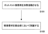
本発明の接着複合体の解体方法は、図1に示すように、上記接着複合体の接合部に対して上記高周波電圧を印加することにより、上記ホットメルト接着剤を加熱溶融させるステップ(S101)と、上記被接着材をこの接合部において剥離するステップ(S102)とを備える。
【0166】
また、この加熱溶融させるステップ(S101)は、この接合部に対して、周波数が1〜5000MHzの範囲にあり、高周波出力0.1〜100kWの範囲にあるこの高周波電圧を、1〜1000秒間の範囲で印加するステップ(S103)を含む。
【0167】
ここで、本発明の接着複合体の解体方法を用いて本発明の接着複合体を解体する場合には、加熱方法が局部加熱であるため大きな加熱炉を必要とせず、また機械的な力がかからないので被接着材が破損しやすい材質や大きな形状であっても破損する可能性を低減できる。そのため、本発明の接着複合体および本発明の接着複合体の解体方法を共に用いることにより、接着複合体の解体方法にかかるコストを低減でき、作業性やリサイクル率を向上させることができる。
【0168】
そして、本発明の接着複合体の解体方法は、被接着材が複数の場合において、少なくともその一つがガラスやセラミックを材質とする被接着材である場合に特に有効である。この場合には、本発明の接着複合体に備わる本発明のホットメルト接着剤を構成する成分である本発明の誘電加熱接着用樹脂組成物に含有される樹脂に、シラン基、チタネート基などが導入されることにより、ガラスを材質とする被接着材と本発明のホットメルト接着剤との接着性がさらに向上し、かつ本発明の接着複合体の解体性に低下させることもないため好ましい。
【0169】
上記のシラン基、チタネート基などを含む単量体としては、たとえば、シラン化合物やチタネート化合物などが挙げられ、具体的には、γ−アミノプロピルトリエトキシシラン、β−(3,4−エポキシシクロヘキシル)−エチルトリメトキシシラン、γ−グリシドキシプロピルトリメトキシシラン、γ−メタクリルオキシプロピルトリメトキシシラン、N−β−(アミノエチル)−γ−アミノプロピルトリメトキシシラン、アシレート系チタネート、ホスフェート系チタネート、アルコラート系チタネートなどが挙げられる。
【0170】
ここで、本発明の接着複合体の解体方法は、特に限定するものではないが、たとえば、次のような構造からなる本発明の接着複合体の解体に好適に利用される。具体的には、ガラス板、セラミック板、樹脂組成物成形品、金属板、木板からなる群より選ばれる任意の1種以上の組合を本発明のホットメルト接着剤により接着して得られる本発明の接着複合体の解体に利用できる。
【0171】
さらに例示すると、ガラス板/本発明のホットメルト接着剤/ガラス板、ガラス板/本発明のホットメルト接着剤/樹脂組成物成形品、ガラス板/本発明のホットメルト接着剤/金属板、熱可塑性樹脂組成物成形品/本発明のホットメルト接着剤/樹脂組成物成形品、金属板/本発明のホットメルト接着剤/金属板、金属板/本発明のホットメルト接着剤/樹脂組成物成形品などの組合せからなる本発明の接着複合体の解体に利用される。
【0172】
本発明の接着複合体の解体方法の具体的な手法としては、特に限定するものではないが、たとえば、最初に、本発明の接着複合体の接合部を電極間に置いて、該電極間に高周波の交流電界を印加させることにより、本発明のホットメルト接着剤中の発熱体(導電物質)を誘電加熱させる。すると、時間の経過と共に本発明のホットメルト接着剤の温度が上昇し、その融点以上になると本発明のホットメルト接着剤は流動した状態となり、被接着材同士は剥離する。そして、このように剥離した状態で交流電流を切るか、あるいは本発明の接着複合体から剥離した被接着材を電界の外に取出し、移動放冷するか、またはエアーなどで冷却することにより、本発明の接着複合体を解体することができる。なお、本発明の接着複合体の解体方法は、本発明のホットメルト接着剤の融点以上であり、かつ被接着材の融点あるいは分解温度以下の温度において、本発明のホットメルト接着剤を溶融させることにより行われることが好ましい。
【0173】
ここで、本発明の接着複合体の解体方法を利用すると、高周波誘電加熱により本発明の接着複合体の接合部のみが加熱される。そのため、本発明の接着複合体全体を加熱炉の中で処理する必要がなく、解体時に消費するエネルギーを少なくすることが可能となる。
【0174】
本発明の接着複合体の解体方法を利用すると、また、本発明の接着複合体の接合部のみを選択的に加熱できる。そのため、本発明の接着複合体が大きな形状の場合や、本発明の接着複合体に備わる被接着材の一部に耐熱性が低い部分を含む場合に、本発明の接着複合体の解体方法は特に有効である。また、本発明の接着複合体の解体方法は、本発明のホットメルト接着剤により被接着材を接着することにより組立てられた部材であるため、自動車、電気、OA機器、建材などに使用された後に回収された場合にも、被接着材の変形および変性を最小限に留めつつも、容易に解体して再利用することができる。
【0175】
【実施例】
<誘電加熱接着用樹脂組成物、ホットメルト接着剤、被接着材の接着方法>
以下、実施例を挙げて本発明の誘電加熱接着用樹脂組成物、ホットメルト接着剤、被接着材の接着方法をより詳細に説明するが、本発明はこれらに限定されるものではない。
【0176】
<実施例1>
まず、表1に示すポリオレフィン系樹脂および導電性粉体を、表1に示す配合割合で予備混合した。次に、バレルをホッパー側から170−180−180℃に温度調節した2軸押出機PCM30φ(池貝鉄工社製)のホッパーに、当該予備混合物を供給し、スクリュー回転数60rpmにて溶融混合した。そして、2軸押出機から押出されたストランドを水浴にて冷却後、切断して導電性物質を含むホットメルト接着剤のペレットを得た。
【0177】
<実施例2〜12>
まず、それぞれ表1に示すポリオレフィン系樹脂および導電性粉体を、それぞれ表1に示す配合割合で予備混合した。次に、それぞれ実施例1と同様にして、予備混合物からホットメルト接着剤のペレットを得た。
【0178】
<比較例1〜4>
まず、それぞれ表2に示すポリオレフィン系樹脂および導電性粉体を、それぞれ表2に示す配合割合で予備混合した。次に、それぞれ実施例1と同様にして、予備混合物からホットメルト接着剤のペレットを得た。
【0179】
【表1】

【表2】
ここで、表1および表2において、
*1:PO−1は、シラン変性G197(ポリエチレン共重合ブレンド物からなるポリオレフィン系樹脂、クレハエラストマー(株)製、融点105℃)を表わす。
*2:PO−2は、シラン変性G1019(ポリエチレン共重合ブレンド物からなるポリオレフィン系樹脂、クレハエラストマー(株)製、融点120℃)を表わす。
*3:Fe100は、ASC100(鉄粉、ヘガネス社製、平均粒径100μm、体積抵抗率(ρ)1.4×10⁻⁵Ω・cm)を表わす。
*4:Fe200は、KIP300(鉄粉、川崎製鉄(株)製、平均粒径200μm、体積抵抗率(ρ)1.6×10⁻⁶Ω・cm)を表わす。
*5:Cu100は、CE−6(銅粉、福田金属箔粉工業(株)製、平均粒径100μm、体積抵抗率(ρ)1.7×10⁻⁶Ω・cm)を表わす。
*6:CFは、HTA(炭素繊維、東邦レーヨン(株)製、平均長さ3mm、体積抵抗率(ρ)1.5×10⁻³Ω・cm)を表わす。
*7:PO−3は、エバフレックスEEA A709(エチレンエチルアクリレート樹脂からなるポリオレフィン系樹脂、三井・デュポンポリケミカル(株)製、融点56℃)を表わす。
*8:PO−4は、TPX(ポリメチルペンテンからなるポリオレフィン系樹脂、三井石油化学(株)製、融点265℃)を表わす。
*9:SGF05は、日東紡績(株)製の体積抵抗率1012Ω・cmのミルドファイバーを表わす。
【0182】
<分析および評価用サンプルの作製>
まず、実施例1〜12および比較例1〜4において得られたホットメルト接着剤のペレットを用いて、下記の成形方法を用いてそれぞれ接着剤プレートを作製し、また特性分析および性能評価に必要となる被接着材プレートを下記の成形方法を用いて作製した。
【0183】
(i)接着剤プレートの成形
実施例1〜12および比較例1〜4において得られたホットメルト接着剤のペレットを、バレルをホッパー側から180−200−200℃に温度調節した射出成形機に投入して、40℃に温度調節されたテストピース金型に射出し、それぞれ100×100×1mm、100×100×3mmの二種類のサイズの接着剤プレートを得た。
【0184】
(ii)被接着材プレートの成形
140℃にて3時間乾燥した30質量%ガラス繊維強化変性ポリブチレンテレフタレート(東洋紡績(株)製、EMC430)のペレットを、バレルをホッパー側から250−260−260℃に温度調節した射出成形機のホッパーに投入して、ASTM D638記載のTYPE I(厚み3.2mmのダンベル型)の引張テストピースを成形した。
【0185】
<特性分析と性能評価>
次に、上記のようにして得られた、実施例1〜12および比較例1〜4のホットメルト接着剤からなる接着剤プレート、上記の被接着材プレートおよび表3に示すその他の各種被接着材プレートを用いて、下記の分析方法および評価方法に従って、実施例1〜12および比較例1〜4において得られたホットメルト接着剤の性能評価を行なった。結果を表1〜表3に示す。
【0186】
(i)誘電正接および誘電損失係数の測定
まず、実施例1〜12および比較例1〜4のホットメルト接着剤からなる接着剤プレートのうち、100×100×3mmのサイズの接着剤プレートから8×8×3mmのサイズの試験片を切り出した。次に、高周波誘電加熱装置(パール工業(株)製、インピーダンスアナライザー)に接続された端子面積Dsが5cm2の導体端子間に、当該試験片を挟んで固定した。そして、当該試験片に周波数40MHzの高周波電荷Qを23℃条件下で与えて端子間の電位差Vを測定し、端子間の電位差Vから静電容量Csと誘電正接(tanδ)を測定した。
【0187】
また、真空中の誘電率ε0を8.85×10⁻¹⁴F/cmとして下記の式(I)より誘電損失係数ε・tanδを求めた。
ε・tanδ=Cs×Ds/(ε0×S)・・・(I)
(ii)接着強度
上記のようにして得られたガラス繊維強化ポリブチレンテレフタレート樹脂成形品(東洋紡績(株)製、EMC430)からなる被接着材プレートを、長さ方向の中央にて切断し、12.7×25.4×3.2mmの被接着材プレート片を得た。
【0188】
次いで、実施例1〜12および比較例1〜4のホットメルト接着剤からなる接着剤プレートのうち、100×100×1mmのサイズの接着剤プレートから12.7×25.4×3mmのサイズの試験片を切出して、当該被接着材プレート片の直線部分に重ね合わせた。
【0189】
そして、図2に示すように、得られた接着剤プレート3a,3b−被接着材プレート5a,5bの複合体を重ねて、33×100×3mmのガラス板1の両端に直線状に、軸を合わせた状態で固定し、当該接着強度評価用複合体100を得た。
【0190】
続いて、高周波誘電加熱装置(パール工業(株)製、商品名インピーダンスアナライザー)に接続された端子面積Dsが5cm2の導体端子間に、当該接着強度評価用複合体100を挟んで固定した。そして、当該接着強度評価用複合体を20mmφのエアシリンダーで2kg/cm 2 加圧した状態で、当該接着強度評価用複合体に、発振時間としてそれぞれ表1〜3において選ばれる1分、5分または20分間にわたり周波数40MHzの高周波電圧を印加して当該接着強度評価用複合体を加熱後、エアブローで1分冷却して接着強度評価用試験片とした。
【0191】
こうして得られた接着強度評価用試験片を23℃、50%RHに調節された試験室に5時間以上放置した。そして、図2に示すように、50℃に温度調節された恒温槽を備えた万能引張試験機UTMI型((株)オリエンテック製)のチャックに、接着強度評価用複合体100を引張剪断変形軸が垂直になるような状態で固定し、5mm/分の変形速度で引張方向7a,7bに引張剪断することにより、当該接着強度評価用試験片の50℃における接着強度を測定した。
【0192】
表1〜表2に示される結果から、実施例1〜12のホットメルト接着剤は、融点が80〜200℃の範囲にあるポリオレフィン系樹脂と、体積抵抗率が10-2Ω・cm以下の導電物質とを含有しており、樹脂組成物全体に対する当該導電物質の含有量が1〜30容量%の範囲にあるため、誘電正接が0.03以上となっており、その結果50℃と比較的高温における接着強度も比較例1〜4のホットメルト接着剤に比べて優れていることがわかる。
【0193】
<実施例13〜18>
本発明のホットメルト接着剤について、他の被接着材との接着強度を調べるために、実施例3のホットメルト接着剤から得られる上記の接着剤プレートを、表3に示した各種被接着材プレート上面側と下面側との間に挿置して、上記の特性分析と性能評価の項目における(ii)接着強度の測定方法と同様にして、実施例3のホットメルト接着剤と他の被接着材との接着強度およびを測定した。結果を表3に示す。
【0194】
【表3】
ここで、表3において、セラミック板は東芝セラミックス(株)製電磁調理器用セラミックス板、アルミ板は古河アルミニウム工業(株)製サッシ用アルミニウム板、ポリアミド樹脂板は東洋紡績(株)製東洋紡ナイロンT−402(ガラス繊維強化ポリアミド樹脂)からなる板、PPS板は東洋紡績(株)製東洋紡PPSTS401(ガラス繊維強化ポリフェニレンサルファイド樹脂)からなる板を表わす。また、サイズはいずれも12×150×5mmである。
【0196】
表3に示される結果より、実施例3のホットメルト接着剤は、ガラスおよびガラス繊維強化ポリブチレンテレフタレート樹脂のみならず、幅広い被接着材に対して優れた接着強度を有することがわかる。
【0197】
<被接着用樹脂組成物>
以下、別の実施例を挙げて本発明の被接着用樹脂組成物をより詳細に説明するが、本発明はこれらに限定されるものではない。
【0198】
<実施例21〜34、比較例21〜30>
まず、表4および表5に示す樹脂、改質材、無機充填材の組合せに基づいて、それらの所定量(質量部)を計量後、予備混合した。この予備混合体を、それぞれシリンダー温度をTm+30℃に調節した直径30mmφの同方向2軸押出機のホッパーに投入し、スクリュー回転数100rpmにて溶融混練してペレットを得た。得られた各々のペレットのうち、ポリエステル系樹脂および/またはポリフェニレンサルファイド系樹脂を含有するペレットは140℃で3時間、ポリアミド系樹脂を含有するペレットは120℃で2時間、ポリアセタール系樹脂および/またはポリオレフィン系樹脂を含有するペレットは80℃で1時間乾燥し、評価用サンプルを得た。
【0199】
そして、下記の特性分析と性能評価の方法により得られた評価用サンプルの性能を評価した。その結果を併せて表4および表5に示す。
【0200】
【表4】
【表5】
表4および表5中の略号は次の通りである。
PBT:ポリブチレンテレフタレート(東洋紡績(株)製、バイロペットEMC700、1MHzにおける誘電正接:0.04、40MHzにおける誘電正接:0.03)
PET:ポリエチレンテレフタレート(東洋紡績(株)製、バイロペットEMC500−01、1MHzにおける誘電正接:0.03、40MHzにおける誘電正接:0.03)
POM:ポリオキチメチレン(ポリプラスチックス(株)製、ジュラコンM90S、1MHzにおける誘電正接:0.006、40MHzにおける誘電正接:0.005)
PA6:ポリアミド6(東洋紡績(株)製、東洋紡ナイロンT800、1MHzにおける誘電正接:0.09、40MHzにおける誘電正接:0.08)
PP:ポリプロピレン((株)グランドポリマー製、E7000、1MHzにおける誘電正接:0.002、40MHzにおける誘電正接:0.003)
RA:エポキシ変性ポリエチレン(日本ポリオレフィン(株)製、レキスパールRA3150)
MP:無水マレイン酸変性ポリプロピレン(グランドポリマー(株)製、MMP006)
ガラス繊維:旭ファイバーグラス(株)製、03JA429
ウイスカー:6チタン酸カリウム(大塚化学(株)製、テイスモーD)
MW:タルク(林化成(株)製、#5000A)
IO:アイオノマー樹脂(三井・デユポンポリケミカル(株)製、ハイミラン1707)
MD:アルキルジベンジリデンソルビトール(新日本理化(株)、ゲルオールMD)
<特性分析と性能評価>
次に、上記のようにして得られた、実施例21〜34および比較例21〜30の被接着用樹脂組成物のペレットを用いて、下記の分析方法および評価方法に従って、実施例21〜34および比較例21〜30において得られた被接着用樹脂組成物のペレットの性能評価を行なった。結果を表4および表5に示す。
【0203】
(i)融点および結晶化温度
まず、被接着用樹脂組成物のペレットから10mgサンプルを切削採取しアルミパンに封入する。次いで、切削採取したサンプルをDSC(示差走査熱量計)の試料容器にセットする。そして、窒素ガス60cm3/分を流しながら、20℃/分の昇温速度にて昇温するのに必要な熱量の標準側との差を自動記録した。得られた記録に基づいて、吸熱ピーク温度を融点(Tm)とした。その後、Tmより30℃高い温度まで昇温して5分間保持した。続いて、10℃/分の降温速度にて降温し、標準側との熱量差を自動記録し、発熱ピーク温度を結晶化発熱ピーク温度(Tc)とした。
【0204】
(ii)曲げ強度
溶融樹脂温度がTm+20℃になるように設定された射出成形機により被接着用樹脂組成物のペレットを溶融した後に、表面温度が50℃に温度調節された金型を使用して、厚さ6.4mm×幅12.7mm×長さ127mmの短冊をエッジゲートにより、射出時間15秒、冷却15秒にて射出成形後、140℃で1時間熱処理をして曲げ試験片とした。
【0205】
この試験片を23℃、RH50%の試験室にて20時間保管後、スパン長100mm、クロスヘッド速度3mm/minに設定した万能引張試験機によりASTM D790に準じて曲げ試験を行い、曲げ強度を計算により求めた。
【0206】
(iii)接着強度
溶融樹脂温度がTm+20℃になるように設定された射出成形機により被接着用樹脂組成物のペレットを溶融した後に、表面温度が50℃に温度調節された試験片金型を使用して、ASTM D638規定のTYPE 1成形品を射出時間15秒、冷却15秒にて射出成形後、140℃で1時間熱処理して被接着材プレートを得た。この被接着材プレートを長さ方向の中央部で切断した。
【0207】
そして、図2に示すように、この切断された被接着材プレート5a,5bの直線部分12.7mm×25.4mmに、100mm×100mm×1mmのホットメルト接着剤プレートから12.7mm×25.4mmの接着剤プレート3a,3bをカットして重合わせた。このラップ部分を、33mm×100mm×3mmのガラス板1の両端に直線状にセットした。
【0208】
そして、これを20mmφのエアシリンダーで0.2MPa加圧した状態で、高周波誘電加熱装置(パール工業(株)製)にて1分間加熱後、0〜3分間の範囲で冷却時間を変えた試験片を作製し、接着強度評価用複合体100とした。
【0209】
次いで、接着強度評価用複合体100を23℃、50%RHに調節された試験室に5時間以上放置した。続いて、図2に示すように、万能引張試験機UTMI型((株)オリエンテック製)のチャックに、ガラス板1の両端に接着した、被接着材プレート5a,5b−接着剤プレート3a,3bからなる接着強度評価用複合体100をセットし、5mm/分の変形速度で引張方向7a,7bに向け引張せん断することにより、50℃における接着強度を測定した。
【0210】
そして、接着後の冷却過程でのズレが発生すると、被接着材間の密着性が低下し接着強度が低下する現象に基づき、接着強度の冷却時間変化からズレが発生しない必要冷却時間を判断した。
【0211】
表4および表5に示されるように、実施例21〜34の被接着用樹脂組成物においては、短時間の冷却時間で、ホットメルト接着剤との優れた接着強度が得られているのに対し、比較例21〜30の被接着用樹脂組成物においては、長時間の冷却時間を設けても、ホットメルト接着剤との優れた接着強度が得られないことがわかる。
【0212】
<接着複合体およびその解体方法>
以下、さらに別の実施例を挙げて本発明の接着複合体および接着複合体の解体方法をより詳細に説明するが、本発明はこれらに限定されるものではない。
【0213】
<各種実験材料の作製>
実施例および比較例中における各種材料は以下の方法により作製した。
【0214】
(i)被接着材プレートの作製
30%質量のガラス繊維強化ポリブチレンテレフタレート(東洋紡績(株)製、EMC430)を加工して、厚さ3.2mm ASTM D638 TYPE1の被接着材プレートを作製した。
【0215】
(ii)ガラス板の作製
厚さ3.4mmの自動車の窓用ガラスを30mm×80mmに切断し、試験用ガラス板を作製した。
【0216】
(iii)ポリオレフィン系接着剤Iの作製
シラン変性G197(ポリエチレン共重合ブレンド物からなるポリオレフィン系樹脂、クレハエラストマー(株)製、融点105℃)に、粒径100μmの鉄粉(ヘガネス社製、ASC100)を60質量%配合して作製した。
【0217】
(iv)ポリオレフィン系接着剤IIの作製
シラン変性G197(ポリエチレン共重合ブレンド物からなるポリオレフィン系樹脂、クレハエラストマー(株)製、融点105℃)に、炭素繊維(東邦レーヨン(株)製、HTA、平均長さ3mm)を10質量%配合して作製した。
【0218】
(v)ポリオレフィン系接着剤IIIの作製
シラン変性G197(ポリエチレン共重合ブレンド物からなるポリオレフィン系樹脂、クレハエラストマー(株)製、融点105℃)をそのまま用いた。
【0219】
(vi)接着剤シートの作製
上記のポリオレフィン系接着剤I、II、IIIのバレルを、それぞれホッパー側から180−200−200℃に温度調整した射出成形機に投入して、40℃に温度調節されたテストピース金型に射出し、それぞれ100mm×100mm×1mm、100mm×100mm×3mmの二種類のサイズの接着剤シートを作製した。
【0220】
<実施例41〜43、比較例41〜45>
表6および表7に示す組合せからなる、実施例41〜43、比較例41〜45の接着複合体を作製し、それぞれの接着複合体の有する特性と性能について、下記の特性分析と性能評価の方法により測定した。その結果を、表6および表7に併せて示す。
【0221】
ここで、比較例41〜45については、誘電加熱により解体することができなかった。そのため、比較のために、比較例42〜45の加熱炉140℃における解体時間を表7に示した。
【0222】
【表6】
【表7】
<特性分析と性能評価>
次に、上記のようにして得られた、実施例41〜43および比較例41〜45の接着複合体を用いて、下記の分析方法および評価方法に従って、実施例41〜43および比較例41〜45において得られた接着複合体の性能評価を行なった。結果を表6および表7に示す。
【0225】
(i)誘電正接の測定
まず、100mm×100mm×3mmのポリオレフィン系接着剤I、II、IIIのシートから8mm×8mm×3mmのサイズの試験片を切出した。次に、高周波誘電加熱装置(パール工業(株)製、インピーダンスアナライザー)に接続された端子面積Dsが5cm2の導体端子間に、当該試験片を挟んで固定した。そして、当該試験片に周波数40MHzの高周波電荷Qを23℃条件下で与えて端子間の電位差Vを測定し、端子間の電位差Vから誘電正接を測定した。
【0226】
(ii)接着強度の測定
図2に示すように、被接着材プレート5a,5bの直線部分の12.7mm×25.4mmに、厚さ1mmのポリオレフィン系接着剤I、II、IIIのシートから12.7mm×25.4mmの接着剤プレート3a,3bをカットして重合わせた。このラップ部分を30mm×80mmのガラス板1の両端に直線状にセットした。これをクリップ((株)ライオン事務器製、NO.111)に挟み、140℃で20分間処理して、接着強度評価用複合体100を作製した。
【0227】
次いで、図2に示すように、加熱炉付テンシロンUTM1型のチャックに、上記の接着強度評価用複合体100をセットし、5mm/分の速度で引張方向7a,7bの方向に引張せん断することにより接着強度を測定した。なお、試験温度は23℃にて実施した。
【0228】
(iv)誘電加熱解体時間および140℃解体時間の測定
誘電加熱解体時間は、高周波誘電加熱装置(パール工業(株)製、インピーダンスアナライザー)に接続された、端子面積が5cm2の導体端子間に、表6および表7に示した各種接着複合体を挿入し、周波数40MHzの高周波電圧を23℃条件下で、いろいろな発振時間で印加し、接着層を溶融させ、被接着材を剥離するまでの時間を測定して求めた。また、140℃解体時間は、表7に示した各種接着複合体を140℃の高温槽に設置して、接着層を溶融させ、被接着材を剥離するまでの時間を測定して求めた。
【0229】
表6および表7に示されるように、実施例41〜43の接着複合体は、優れた接着強度を有する一方で、短時間の誘電加熱解体時間で接着層を溶融させ被接着材を剥離可能であるのに対し、比較例41〜45の接着複合体は、140℃の高温で処理しても、非常に長時間の誘電加熱解体時間を経てようやく接着層を溶融させ被接着材を剥離可能であることがわかる。すなわち、従来の加熱炉140℃における解体に比較し、本発明の実施例による接着複合体の解体時間は大幅に短縮されていることがわかる。
【0230】
今回開示された実施の形態および実施例はすべての点で例示であって制限的なものではないと考えられるべきである。本発明の範囲は上記した説明ではなくて特許請求の範囲によって示され、特許請求の範囲と均等の意味および範囲内でのすべての変更が含まれることが意図される。
【0231】
【発明の効果】
上記の結果より、本発明の誘電加熱接着用樹脂組成物は、非常に短時間の高周波電圧の印加により加熱溶融させることができ、比較的高温でも優れた接着強度を有する。そのため、本発明の誘電加熱接着用樹脂組成物は、高周波電圧を印加することにより加熱溶融する性質を有するホットメルト接着剤のバインダとして好適に使用可能である。
【0232】
また、本発明のホットメルト接着剤は、非常に短時間の高周波電圧の印加により加熱溶融させることができ、比較的高温でも優れた接着強度を有する。そのため、本発明のホットメルト接着剤を用いることにより、従来のホットメルトタイプ接着剤では必要とされていた加熱炉を用いる必要がなく、ホットメルト接着剤を用いる製品の製造設備のコンパクト化、製造工程の簡略化が可能となり、製造ラインの生産性を著しく高めることができる。また、本発明のホットメルト接着剤をシート状に成形して用いることにより、大型部材同士の接着工程においても、非常に短時間の高周波電圧の印加により均一で優れた接着強度を得ることができる。
【0233】
そして、本発明の被接着材同士の接着方法は、非常に短時間の高周波電圧の印加により優れた接着強度を実現することができる。そのため、本発明の被接着材同士の接着方法を用いることにより、従来のホットメルトタイプ接着剤を用いた接着方法では必要とされていた加熱炉を用いる必要がなく、ホットメルト接着剤を用いた接着方法により製造される製品の製造設備のコンパクト化、製造工程の簡略化が可能となり、製造ラインの生産性を著しく高めることができる。また、本発明の被接着材同士の接着方法を用いることにより、大型部材同士の接着工程においても、非常に短時間の高周波電圧の印加により均一で優れた接着強度を得ることができる。
【0234】
また、上記の結果より、本発明の被接着用樹脂組成物は、ホットメルト接着剤による接着の際に、ホットメルト接着剤の加熱により溶融あるいは軟化し難く、かつ短時間に再硬化して優れた接着性を示す、ホットメルト接着剤の被接着材として用いられる被接着用樹脂組成物である。
【0235】
さらに、上記の結果より、本発明の接着複合体は、加熱炉を使用することなく高周波電圧の印加により短時間に解体ができ、被接着体の材質が良好に再使用できる、高周波電圧を印加することにより解体可能な、接着複合体である。
【0236】
そして、上記の結果より、本発明の接着複合体の解体方法は、上記の接着複合体の接着部分のみを効率的に加熱することにより、解体時におけるエネルギー、時間および労力を省力化することができる、接着複合体の解体方法である。
【0237】
したがって、本発明の接着複合体の解体方法は、加熱炉を使用せず、また短時間に解体が可能なうえに、接着層のみが選択的に加熱溶融されるため、解体に要するエネルギーの省力化が実現できる。また、本発明の接着複合体の解体方法は、材料の破損や劣化の度合いが低いため、大型部材の回収が可能となり、産業界に寄与すること大である。
【図面の簡単な説明】
【図1】 本発明の接着複合体の解体方法の概略を示すステップ図である。
【図2】 接着複合体の接着強度の測定方法の一例を示す概略図である。
【符号の説明】
1 ガラス板、3a,3b 接着剤プレート、5a,5b 被接着材プレート、7a,7b 引張方向、100 接着強度評価用複合体。[0001]
BACKGROUND OF THE INVENTION
The present invention relates to a resin composition for dielectric heating adhesion. More specifically, the present invention can be heated and melted by applying a high-frequency voltage for a short time without using a heating furnace, and is the same or different material selected from the group consisting of glass, ceramics, metals, and resins. The present invention relates to a resin composition for dielectric heating adhesion that is excellent in adhesive strength at a relatively high temperature when used for bonding between each other.
[0002]
The present invention also relates to a hot melt adhesive containing the resin composition for dielectric heating adhesion of the present invention. Furthermore, the present invention relates to a method for bonding an adherend using the resin composition for dielectric heating bonding of the present invention.
[0003]
And this invention relates to the resin composition for to-be-adhered used as a to-be-adhered material of the hot-melt-adhesive of this invention.
[0004]
The present invention also relates to an adhesive composite comprising the hot melt adhesive of the present invention and an adherend. Furthermore, the present invention relates to a method for disassembling the adhesive composite of the present invention.
[0005]
[Prior art]
In recent years, the progress of the function of adhesives has been remarkable, and adhesives are used in many fields such as electricity, machinery, civil engineering, architecture, wood, paper, textiles, and chemistry. In addition, with the advancement of the function of adhesives, adhesives that have been used as secondary materials in the past have recently been used for bonding main materials of important structural parts. For example, adhesives are often used in places where reliability is required, such as bonding between brake linings of automobiles and bonding of honeycomb structures for aircraft lightweight reinforcement measures.
[0006]
Using adhesives instead of screws, nails, welding, etc., which have been used for general purposes, can simplify the manufacturing process and often achieve significant cost savings. If an adhesive is used, the product can be reduced in weight. And if this weight reduction by adhesives is applied to automobiles, railway vehicles, airplanes, etc., it will indirectly contribute to labor saving of motive energy, and moreover, carbon dioxide that may indirectly cause global environmental problems This will contribute to the reduction of emissions. Therefore, the importance of adhesives is increasing in each industrial field.
[0007]
As described above, the same or different materials selected from the group consisting of large glass, ceramics, metals, and resins, such as those used in the fields of automobiles, railway vehicles, aircraft, civil engineering and architecture In the past, in order to improve the adhesion and / or durability of the bonding, a primer is applied to the surface of the adherend before applying the adhesive, and the primer is dried and / or cured. Later, an adhesive was applied to the surface of the primer coating, and the adhesive was often dried and / or cured to bond the adherends together.
[0008]
However, when chemical pretreatment of the adherend is performed using a primer, it takes a long time to dry the solvent contained in the primer and / or adhesive and to cure the primer and / or adhesive. There was a problem, and there was a problem that the use of solvents adversely affects the work environment and the global environment.
[0009]
Therefore, in order to solve the above problems, hot melt adhesives have been widely used industrially recently. Hot melt adhesives contain little or no solvent and therefore have little adverse effect on the work environment and the global environment, have low risk of ignition, and are easy to handle because they are solid at room temperature. In addition, it can be said to be an adhesive suitable for high-speed and large-scale processing by automation since it solidifies as soon as it is left after melting and bonding.
[0010]
However, a general hot melt adhesive has a drawback that the required performance is often not obtained because of low adhesive strength at high temperatures. In addition, when a high-temperature type hot melt adhesive is used, a large heating furnace is necessary because the melting point of the adhesive is high, and thus the manufacturing cost must be increased accordingly. In addition, when a hot melt adhesive is used, a cycle of a heating process and a cooling process is necessary, and there are major obstacles in industrialization, and there is no choice but to put it into practical use.
[0011]
Therefore, in order to obtain an adhesive having the advantages of the hot melt adhesive as described above and overcoming the disadvantages as described above, many efforts have been made to develop a hot melt adhesive in various fields. Yes. The adhesive containing the resin composition for dielectric heating adhesion in the present invention is a kind of hot melt adhesive, and is heated and melted by applying a high frequency voltage in a state where the adhesive is interposed between the adherends. Then, it has a function of bonding the materials to be bonded together by being cooled and solidified thereafter. In the case of using the adhesive containing the resin composition for dielectric heating adhesion of the present invention, an applicator having a large heating furnace is not required. The bonding process can be simplified. Therefore, productivity can be greatly improved by using an adhesive containing the resin composition for dielectric heating adhesion of the present invention.
[0012]
Here, high-frequency heat generation is considered to be due to heat generation due to molecular friction based on molecular polarization, and generally the heat generation efficiency due to the application of high-frequency voltage of a thermoplastic resin is the dielectric constant (ε), dielectric loss tangent ( tan δ) and the dielectric loss coefficient {(ε) × (tan δ)}, which is the product of these, are considered to be superior. Among thermoplastic resins, polyolefin resins mainly composed of hydrocarbon bonds, such as polyethylene resins and polypropylene resins, are non-polar and therefore have low dielectric constant (ε) and dielectric loss tangent (tan δ) for high-frequency heating. Is considered unsuitable.
[0013]
On the other hand, polyolefin resin is excellent in toughness, impact resistance, flexibility, workability, transparency, acid resistance, alkali resistance, low permeability to water, thermal stability, electrical insulation, etc. Since it exhibits high viscosity, it can be said that it has properties suitable as a binder resin for adhesives. In addition, since the polyolefin-based resin is the most mass-produced resin in the world, it is excellent in that it is easily available and inexpensive. Therefore, there is a strong demand for the development of a technology that makes it possible to use a polyolefin-based resin as a binder resin for a hot-melt adhesive capable of dielectric heating.
[0014]
In fact, in order to overcome the above-mentioned problems while taking advantage of the excellent properties of polyolefin resins, technology that mixes polyolefin resins with highly polar resins such as polyvinyl chloride resin and dielectric loss in thermoplastic resins A technique for blending an inorganic substance having a large coefficient (for example, see Patent Document 1) and a technique for blending a ferroelectric material in a thermoplastic resin (for example, see Patent Document 2) have been proposed. However, due to insufficient heat generation, it takes too much time for heating and is not practical. Polyvinyl chloride resin is harder to handle during construction due to its higher specific gravity than polyolefin resin, and incineration may produce substances that adversely affect the human body and the global environment, including dioxin. There's a problem.
[0015]
In addition, since the amount of heat generated by dielectric heating to which a high frequency voltage is applied is completely insufficient, electromagnetic induction heating using induction heating of a conductor with a high frequency coil by blending a ferromagnetic material is also used (for example, However, since the efficiency of induction heating of such a composite is low, when the heat capacity of the material to be bonded is insufficient compared to the heat capacity of the adhesive, the adhesive is raised to a temperature necessary for bonding. Takes a long time, so the productivity is low, and at present it is not in a stage where it can be put into practical use.
[0016]
Furthermore, a film is disclosed in which an electromagnetic wave absorber such as ferrite is blended or applied to a nonpolar resin film such as a polyolefin resin (see, for example, Patent Document 4). Further, a thermoplastic resin composition in which a high-frequency or microwave sensitizer in which 3 to 30 parts by mass of a liquid polar substance is adsorbed to 2 to 20 parts by mass of an inorganic other porous powder is added to 100 parts by mass of a thermoplastic resin. (For example, refer to Patent Document 5). However, even if these techniques are used, the polyolefin resin can be heated and melted in a sufficiently short time, and it is not yet possible to use it as a resin composition for dielectric heating adhesion having sufficiently strong adhesiveness. .
[0017]
And ultra high molecular weightpolyethyleneIn addition, a technique of adding a radio frequency sensitizer such as zinc oxide, bentonite, and an alkali metal or alkaline earth metal aluminosilicate and a substance suitable for improving radio frequency sensitivity is disclosed (for example, Patent Documents). 6). Moreover, the technique which adds the radio frequency energy sensitizer which consists of a composition which mix | blended 4-10 mass% N-ethyltoluene sulfonamide with the thermoplastic polymer is disclosed (for example, refer patent document 7). Furthermore, the technique of mix | blending 20-200 mass parts inorganic powder which has crystal water with 100 mass parts of polyolefin resin is disclosed (for example, refer patent document 8). Q. X. Nguyen, R.A. Gauvin, Y.M. The technique of adding sodium aluminosilicate to ultra high molecular weight polyethylene, as disclosed in Belanger; ANTEC '91, p2245-2247, is generally well known. As commercially available microwave sensitizers, those manufactured by STRUKTOL (USA), FREQUON (trade name), and the like are well known. However, even if these techniques are used, it is still possible to heat and melt polyolefin resin in a sufficiently short time, and it is still not possible to use it as a resin composition for dielectric heating adhesion having sufficiently strong adhesiveness. It is.
[0018]
Further, it is well known that among polyolefin resins, ethylene copolymers having a polar group such as ethylene-vinyl acetate copolymer and ethylene-methyl acrylate copolymer can be fused at high temperature. And the technique which mixes polyamide, a vinyl polymer, polyester, or polyurethane with a propylene-alpha-olefin block copolymer is disclosed (for example, refer patent document 9).
[0019]
Further, a resin composition is disclosed in which a propylene polymer and an ethylene copolymer composed of ethylene and an unsaturated carboxylic acid and / or an unsaturated carboxylic acid derivative are blended (see, for example, Patent Document 10). . However, at present, these copolymers are insufficient in terms of adhesiveness and time required for heating.
[0020]
Here, as described above, in order to shorten the bonding process time of the material to be bonded, if an adhesion method that performs rapid heating using a hot melt adhesive is selected, not only the hot melt adhesive but also the material to be bonded can be obtained. Since it takes time to re-harden the material to be bonded after being softened or melted, there was a problem in practical use. In particular, when the heat capacity of the adherend is insufficient compared to the heat capacity of the hot melt adhesive, it takes a long time to raise the hot melt adhesive to the temperature required for bonding, so the productivity becomes low and practical. Not right.
[0021]
Therefore, as the heating rate of the hot melt adhesive is accelerated as described above, there has been an increasing demand for the development of a material that can withstand high-speed heating and solidification of the adherend. Therefore, in recent years, although there are still few examples, several companies etc. have started working on the development of such a material to be bonded for hot melt adhesives.
[0022]
For example, a technique for an interior material including a packing resin layer made of polyethylene terephthalate that is attached to a base material such as a door trim with high adhesiveness by a hot melt adhesive is disclosed (for example, Patent Documents). 11). However, this technique is only intended to improve the adhesion with a general hot melt adhesive, and this document does not describe a hot melt adhesive capable of high frequency dielectric heating.
[0023]
Moreover, until now, wastes of various parts assembled using conventionally known adhesives such as those in the automobile industry and the home appliance industry have been discarded after being crushed because it is difficult to peel off the bonded portions. For this reason, in spite of the demand for promotion of recycling in all industries, various materials constituting waste of various parts cannot be separated and reused or recycled.
[0024]
In order to overcome such problems, in some parts, the use of a hot melt adhesive is attempted, and the hot melt adhesive is heated and melted to peel off the material to be bonded. Achieved results. However, in a part assembled using a conventionally known hot melt adhesive, it is necessary to perform high temperature processing on the entire assembled part in a heating furnace, so the cost due to the necessity of a large heating furnace. There is a certain limit to the effect of promoting reuse due to the increase in the quality of materials and the deterioration of the quality of recycled parts due to heating.
[0025]
Also, in order to disassemble a part assembled with a conventionally known hot melt adhesive, a cycle of a heating process and a cooling process is necessary, and it is necessary to heat up to a part other than the bonded part, resulting in poor heating efficiency. It becomes a big obstacle to industrialization. Therefore, a method for disassembling a part assembled with a conventionally known hot melt adhesive has not been put into practical use in earnest.
[0026]
Therefore, in order to overcome such problems, the parts to be bonded are peeled off by induction heating of the parts bonded with a hot melt adhesive containing a thermoplastic resin composition containing a heating element that generates heat by high frequency induction. Dismantling methods have been developed (see, for example, Patent Document 12). However, it is necessary to insert a metal into the thermoplastic resin composition in advance as a heating element, and it cannot be said that the heating efficiency is sufficient.
[0027]
[Patent Document 1]
JP 52-68273 A
[0028]
[Patent Document 2]
JP 54-161645 A
[0029]
[Patent Document 3]
JP 62-132983 A
[0030]
[Patent Document 4]
Japanese Patent Laid-Open No. 6-182876
[0031]
[Patent Document 5]
JP-A-6-228368
[0032]
[Patent Document 6]
Japanese Patent Publication No. 5-42982
[0033]
[Patent Document 7]
JP-A-2-182419
[0034]
[Patent Document 8]
JP-A-2-129243
[0035]
[Patent Document 9]
Japanese Patent Publication No. 8-193150
[0036]
[Patent Document 10]
Japanese Patent Laid-Open No. 10-273568
[0037]
[Patent Document 11]
JP 2001-58382 A
[0038]
[Patent Document 12]
JP 2002-144341 A
[0039]
[Problems to be solved by the invention]
Based on the above situation, the object of the present invention is to provide a resin composition for dielectric heating adhesion that can be heated and melted by applying a high-frequency voltage for a very short time and has excellent adhesive strength even at a relatively high temperature. It is.
[0040]
Another object of the present invention is to provide a hot melt adhesive that can be heated and melted by applying a high-frequency voltage for a very short time and has excellent adhesive strength even at a relatively high temperature.
[0041]
Another object of the present invention is to provide a method for bonding materials to be bonded that can realize excellent bonding strength by applying a high-frequency voltage for a very short time.
[0042]
In addition, another object of the present invention is to provide a hot melt adhesive that is not easily melted or softened by heating of the hot melt adhesive and re-cured in a short time and exhibits excellent adhesiveness. An object of the present invention is to provide an adherend resin composition used as an adherend for a melt adhesive.
[0043]
Further, another object of the present invention is to dismantle in a short time by applying a high-frequency voltage without using a heating furnace, and to dismantle by applying a high-frequency voltage in which the material of the adherend can be reused well. It is possible to provide an adhesive composite.
[0044]
Another problem of the present invention is that the above-mentioned adhesive complex can save energy, time, and labor during disassembly by efficiently heating only the bonded portion of the above-mentioned adhesive complex. Is to provide a method of dismantling.
[0045]
[Means for Solving the Problems]
In order to provide the above-described dielectric heating adhesive resin composition, hot-melt adhesive, and a method for adhering materials to be bonded, the present inventors include a conductive substance in a polyolefin resin and a dielectric resin of the polyolefin resin. The idea of increasing the tangent was obtained, and extensive studies were conducted using various conductive materials. At the end of the study, the volume resistivity is 10-2It has been found that the dielectric loss tangent of the polyolefin resin can be increased by containing a conductive substance having a resistance of Ω · cm or less, and the dielectric heat-bonding resin composition of the present invention, the hot melt adhesive, and the adhesion between the adherends Completed the method.
[0046]
That is, the dielectric heating adhesive resin composition of the present invention has a polyolefin resin having a melting point in the range of 80 to 200 ° C. and a volume resistivity of 10-2A conductive material that is Ω · cm or less, the content of the conductive material is in the range of 1 to 30% by volume, and the dielectric loss tangent at 23 ° C. is 0.03 or more at a frequency of 40 MHz. Features.
[0047]
Here, it is more desirable that the content of the conductive material is in the range of 5 to 25% by volume. In addition, the dielectric heat-bonding resin composition of the present invention preferably has a dielectric loss tangent of 0.1 or more at 23 ° C. at a frequency of 40 MHz.
[0048]
In the resin composition for dielectric heating adhesion of the present invention, the volume resistivity of this conductive material is 10-FourIt is preferable that it is below Ω · cm. Further, the conductive material includes iron, copper, silver, an alloy containing iron as a main component, an alloy containing copper as a main component, an alloy containing silver as a main component, carbon, and an inorganic compound containing carbon as a main component. It is desirable to contain one or more materials selected from
[0049]
The conductive material preferably has one or more shapes selected from the group consisting of powder, granule, granule, needle, fiber, and scale. At this time, it is desirable that the conductive material has an average particle diameter in the range of 10 to 500 μm. Further, it is recommended that the conductive material be contained in a state of being uniformly dispersed in the resin composition for dielectric heating adhesion.
[0050]
In addition, the conductive material may have one or more shapes selected from the group consisting of a net shape, a thin film shape, a string shape, and a rod shape. At this time, the resin composition for dielectric heating adhesion of the present invention may have a structure in which a layer containing this conductive substance and a layer containing a resin composition containing a polyolefin resin are laminated. Here, it is preferable that the resin composition for dielectric heating bonding of the present invention is formed into a thin film.
[0051]
Furthermore, it is preferable that the resin composition for dielectric heat bonding of the present invention is heated and melted by applying a high-frequency voltage, and then solidified by cooling to exhibit adhesiveness. In this case, the resin composition for dielectric heating adhesion of the present invention is applied with a high-frequency voltage in the range of 1 to 5000 MHz and a high-frequency output in the range of 0.1 to 100 kW in the range of 1 to 1000 seconds. It is desirable to melt by heating.
[0052]
Moreover, the hot-melt adhesive of the present invention is characterized by containing the resin composition for dielectric heating adhesion.
[0053]
And the adhesion method of the to-be-adhered material of this invention is a range whose frequency is 1 to 5000 MHz with respect to the said hot-melt-adhesive pinched | interposed between to-be-adhered materials, and the range of 0.1-100 kW high frequency output Including a step of heating and melting by applying the high frequency voltage in the range of 1 to 1000 seconds.
[0054]
In order to solve the above-mentioned problems, the inventors of the present invention provide a resin composition that is difficult to melt or soften by heating because of its high melting point, and that is easily re-cured in a short time because of its high crystallization exothermic peak temperature. The idea that it should be used as an adhesive for hot melt adhesives was obtained, and extensive studies were conducted using various types of resin compositions. And after the examination, the present inventors are a resin composition for adhesion containing a crystalline thermoplastic resin and having a bending strength at 23 ° C. in the range of 100 to 400 MPa, and this crystalline heat The plastic resin has a melting point in the range of 150 to 350 ° C., and the difference between this melting point and the crystallization exothermic peak temperature in the temperature lowering process from the molten state at a temperature lowering rate of 10 ° C./min is 0 to 70 ° C. Adhesives using crystalline thermoplastic resins in the range of 1 are difficult to melt or soften by heating and are easy to re-harden, so they are suitable for use as hot melt adhesives. As a result, the resin composition for adhesion of the present invention was completed.
[0055]
That is, the adherend resin composition of the present invention is an adherend resin composition used as an adherend of a hot melt adhesive, and the adherend resin composition contains a crystalline thermoplastic resin. In addition, the resin composition for adhesion having a bending strength at 23 ° C. in the range of 100 to 400 MPa, and the crystalline thermoplastic resin has a melting point in the range of 150 to 350 ° C. It is a resin composition for adhesion, which is a crystalline thermoplastic resin having a difference from the crystallization exothermic peak temperature in the temperature lowering process from the molten state at a rate of 10 ° C./min in the range of 0 to 70 ° C. .
[0056]
Here, it is preferable that the resin composition for adhesion of the present invention has a dielectric loss tangent in a range of 0 to 0.1 at 23 ° C. at a frequency of 40 MHz.
[0057]
Moreover, it is preferable that this crystalline thermoplastic resin contains a polyester-type resin. Furthermore, it is more desirable that the crystalline thermoplastic resin contains a polyester resin and a polyolefin resin.
[0058]
And it is recommended that the resin composition for adhesion of this invention contains 1 or more types of crystal nucleating agents chosen from the group which consists of a fatty-acid metal salt, a benzoate, a sorbitol type compound, a talc, and a clay. Moreover, it is preferable that the resin composition for adhesion of this invention contains 1 or more types of reinforcing agents chosen from the group which consists of a fibrous reinforcing material, a coupling agent, and a mineral reinforcing material.
[0059]
Moreover, it is desirable for the resin composition for adhesion of the present invention to have an adhesive strength of 1.0 to 10 MPa with a hot melt adhesive that melts by high-frequency dielectric heating. Here, the hot melt adhesive has a polyolefin resin having a melting point in the range of 80 to 200 ° C. and a volume resistivity of 10-2A hot melt adhesive having a dielectric loss tangent of 0.03 or more at 23 ° C. at a frequency of 40 MHz, and containing the conductive substance in the hot melt adhesive. It is recommended that the amount be in the range of 1-30% by volume.
[0060]
In addition, the present inventors provide a hot melt adhesive that contains a dielectric heating adhesive resin composition and is heated and melted by applying a high-frequency voltage, in order to provide the above-mentioned adhesive composite and the method for disassembling the adhesive composite. The idea is to use an adhesive composite comprising an adhesive and an adherend bonded to the bonded portion by this hot melt adhesive, and an adhesive composed of various types of hot melt adhesives and adherends. The composite body was prototyped and earnestly studied. And after the examination, the present inventors have a polyolefin resin having a melting point in the range of 60 to 200 ° C. and a volume resistivity of 10-2And a conductive material having a resistance of Ω · cm or less, a dielectric loss tangent at 23 ° C. at a frequency of 40 MHz of 0.03 or more, and a conductive composition of 1 to 30% by volume of the conductive material. Can be disassembled in a short time by applying a high-frequency voltage without using a heating furnace, and the material of the adherend can be reused well, dismantling by applying a high-frequency voltage The present inventors have found that an adhesive complex can be obtained, and completed the adhesive complex and the method for disassembling the adhesive complex of the present invention.
[0061]
That is, the adhesive composite of the present invention is an adhesive composite comprising a hot melt adhesive and an adherend bonded at the joint by the hot melt adhesive. A hot-melt adhesive containing a heat-bonding resin composition and heated and melted by applying a high-frequency voltage. This dielectric heat-bonding resin composition has a melting point in the range of 60 to 200 ° C. And the volume resistivity is 10-2A dielectric material having a dielectric loss tangent under a condition of 23 ° C. at a frequency of 40 MHz of 0.03 or more, and the dielectric heating adhesion of the conductive material. The content in the resin composition for use is an adhesive composite that can be disassembled by applying a high-frequency voltage in the range of 1 to 30% by volume.
[0062]
Here, it is preferable that the dielectric loss tangent of the dielectric heating adhesive resin composition at 23 ° C. at a frequency of 40 MHz is 0.1 or more.
[0063]
The volume resistivity of this conductive material is 10-FourIt is desirable that it is below Ω · cm. Further, the conductive material includes iron, copper, silver, an alloy containing iron as a main component, an alloy containing copper as a main component, an alloy containing silver as a main component, carbon, and an inorganic compound containing carbon as a main component. It is recommended to contain one or more materials selected from
[0064]
The conductive material has one or more shapes selected from the group consisting of powder, granules, granules, needles, fibers, scales, and the dielectric heating adhesive resin composition. It is preferable that it is contained in a uniformly dispersed state.
[0065]
Further, it is desirable that the dielectric loss tangent of the adherend at a frequency of 40 MHz under the condition of 23 ° C. is in the range of 0 to 0.1. Furthermore, it is recommended that the dielectric loss tangent of the resin composition for dielectric heating adhesion at a frequency of 40 MHz is larger than twice the dielectric loss tangent of the adherend at a frequency of 40 MHz.
[0066]
The method for disassembling an adhesive composite according to the present invention includes a step of heating and melting the hot melt adhesive by applying the high-frequency voltage to the joint, and peeling the adherend at the joint. A step of disassembling the above-mentioned adhesive complex.
[0067]
Here, in the step of heating and melting, the high frequency voltage having a frequency in the range of 1 to 5000 MHz and a high frequency output of 0.1 to 100 kW is applied to the joint portion in a range of 1 to 1000 seconds. Preferably, the step of applying is included.
[0068]
DETAILED DESCRIPTION OF THE INVENTION
Hereinafter, the present invention will be described in more detail with reference to embodiments.
[0069]
<Resin heating adhesive resin composition>
First, the resin composition for dielectric heating adhesion will be described.
[0070]
Here, in the present specification, the resin composition for dielectric heating adhesion is a hot melt having the property of adhering materials to be bonded by heating and melting by applying a high frequency voltage and then solidifying by cooling. The resin composition which can be used suitably as a binder of an adhesive shall be pointed out.
[0071]
Next, the dielectric loss tangent (tan δ) of the resin composition for dielectric heating adhesion of the present invention will be described.
[0072]
Here, the dielectric loss tangent (tan δ) refers to the loss factor (tan δ) of the complex dielectric constant. Generally, the heat generation efficiency due to the application of the high frequency voltage of the thermoplastic resin is the dielectric constant (ε), the dielectric loss tangent (tan δ) and these It is considered that the larger the dielectric loss coefficient {(ε) × (tan δ)}, which is the product of
[0073]
The dielectric tangent (tan δ) of the resin composition for dielectric heating adhesion of the present invention at 23 ° C. at a frequency of 40 MHz (hereinafter simply referred to as (tan δ) of the resin composition for dielectric heating bonding of the present invention) is It must be 0.03 or more, preferably 0.1 or more. When the dielectric loss tangent (tan δ) of the resin composition for dielectric heating adhesion of the present invention is less than 0.03, there is a problem that heat generation is poor and the hot melt adhesive does not melt or heating for a long time is required. Because.
[0074]
Next, the polyolefin resin (hereinafter simply referred to as the polyolefin resin used in the present invention) used in the dielectric heating adhesive resin composition of the present invention will be described.
[0075]
Here, in general, an olefin means an unsaturated hydrocarbon having one carbon-carbon double bond and high reactivity, with ethylene and propylene being representative examples. In general, a polyolefin-based resin refers to a resin produced by a polymerization reaction of an olefin monomer, with polyethylene and polypropylene being representative examples.
[0076]
The polyolefin resin used in the present invention is not particularly limited as long as required characteristics are satisfied, and conventionally known polyolefin resins and diene resins can be used. Specific examples of the polyolefin resin include a polyethylene resin, a polypropylene resin, a polyethylene copolymer resin, a polypropylene copolymer resin, an ethylene-propylene copolymer resin, and an ethylene-α olefin copolymer resin.
[0077]
Here, as the polyolefin resin used in the present invention, one or two or more of the aforementioned polyolefin resins can be mixed and used at the same time. In addition, there may be a doubt that the diene resin may not be included in the polyolefin resin. However, in the present specification, the term “polyolefin resin” includes a diene resin for convenience of explanation.
[0078]
In addition, the polyolefin resin used in the present invention includes vinyl acetate, methacrylic acid, acrylic acid, methyl methacrylate, ethyl acrylate, butyl acrylate, methacrylate, and the like in a range of 3 to 50 mol% of the entire polyolefin resin. It is preferable to contain as a copolymerization component. When the monomer component content is less than 3 mol%, the adhesion tends to decrease. When the monomer component content exceeds 50 mol%, the heat resistance of the polyolefin resin is lost. It may be broken.
[0079]
And it is preferable that the polyolefin-type resin used for this invention contains the monomer containing a carboxylic anhydride group, an epoxy group, a hydroxyl group, an isocyanate group, a silanol group etc. as a copolymerization component or a graft polymerization component. Among the above-mentioned monomers, unsaturated carboxylic acid and glycidyl methacrylate are particularly preferable as the copolymer component, and maleic anhydride is particularly preferable as the graft polymerization component.
[0080]
When the above-mentioned functional group is introduced into the polyolefin resin used in the present invention, when the material to be bonded of the hot melt adhesive of the present invention is a reinforced thermoplastic resin, the hot melt adhesive of the present invention and the reinforcement Adhesiveness with a thermoplastic resin can be improved.
[0081]
And the melting point of the polyolefin-type resin used for this invention needs to exist in the range of 80-200 degreeC, and if it exists in the range of 90 to 180 degreeC, it is more preferable. When the melting point is less than 80 ° C., there is a problem that the adhesive strength at a high temperature of the adhesive containing the polyolefin resin is insufficient, and when the melting point exceeds 200 ° C., the polyolefin resin is contained. There is a problem that it takes too much time to melt the adhesive.
[0082]
Here, the content of the polyolefin resin in the resin composition for dielectric heating adhesion of the present invention is preferably in the range of 70 to 99% by volume, and more preferably in the range of 75 to 95% by volume. When the content of the polyolefin resin is less than 70% by volume, the flowability at the time of molding tends to decrease or the adhesive strength tends to decrease, and when the content of the polyolefin resin exceeds 99% by volume, the high frequency There is a tendency not to melt by heating.
[0083]
Subsequently, a conductive material (hereinafter simply referred to as a conductive material used in the present invention) used in the resin composition for dielectric heating adhesion of the present invention will be described. Here, in this specification, the conductive substance is a general term for substances having conductivity, and the material thereof is not limited.
[0084]
Here, in general, induction heating generates random eddy current in a conductor to be heated by electromagnetic induction and generates heat by resistance, while dielectric heating applies voltage to a nonconductor to generate internal owing to molecular polarization. Use frictional heat. In general, the above-mentioned degree of internal friction is evaluated in the form of dielectric loss tangent (tan δ).
[0085]
The volume resistivity (ρ) is 10 in the dielectric heating adhesive resin composition of the present invention.-2When a conductive material having a resistance of Ω · cm or less is blended, the dielectric loss tangent (tan δ) of the resin composition with respect to the application of the high frequency voltage increases to 0.03 or more, and the dielectric loss tangent (tan δ) and dielectric constant (ε) The dielectric loss coefficient {(ε) × (tan δ)} that is the product of
[0086]
Here, the volume resistivity (ρ) is 10-2A conductive substance having a very small dielectric loss tangent (tan δ) of 0.0001 or less is generally blended with a polyolefin resin having a dielectric loss tangent (tan δ) of 0.01 to 0.03. It can be said that the increase of the dielectric loss tangent (tan δ) to 0.03 or more is a result that has not been predicted from conventional technical common sense.
[0087]
In high-frequency heating, if the dielectric loss coefficient {(ε) × (tan δ)} is large, the heat generation amount is also large, so that the volume resistivity (ρ) is 10-2In the resin composition for dielectric heating adhesion of the present invention in which the dielectric loss tangent (tan δ) is increased to 0.03 or more by containing a conductive material of Ω · cm or less, the rate of temperature rise with respect to application of a high frequency voltage is increased. Get faster. As a result, the time required for melting the hot melt adhesive of the present invention containing the resin composition is also shortened.
[0088]
Here, the volume resistivity (ρ) of the conductive material used in the present invention is 10-2Must be Ω · cm or less, 10-FourIt is preferable if it is Ω · cm or less. The volume resistivity (ρ) of the conductive material is 10-2If it exceeds Ω · cm, the dielectric loss tangent hardly rises, and there is a problem that heating takes time.
[0089]
The material of the conductive material used in the present invention is not particularly limited, and is conductive and has a volume resistivity (ρ) of 10-2Any substance that is Ω · cm or less can be used. As a specific example of the material of the conductive material used in the present invention, the volume resistivity (ρ) is 10-2Iron, copper, silver, an alloy containing iron as a main component (hereinafter simply referred to as an iron-based alloy), an alloy containing copper as a main component (hereinafter simply referred to as a copper-based alloy), Examples thereof include an alloy containing silver as a main component (hereinafter simply referred to as a silver-based alloy), carbon, and an inorganic compound containing carbon as a main component (hereinafter simply referred to as a carbon-based compound).
[0090]
Among the conductive materials described above, iron or iron-based alloys such as α iron, β iron, γ iron, and carbon steel, carbon or carbon-based compounds such as carbon fiber and carbon black, and the like are used for the dielectric heating of the present invention. This is particularly preferable from the viewpoint of the influence on the resin contained in the adhesive resin composition and the economical aspect. Furthermore, the conductive materials described above may be used singly or in combination of two or more.
[0091]
The content of the conductive material used in the present invention relative to the entire resin composition for dielectric heating adhesion of the present invention (hereinafter simply referred to as the content of the conductive material used in the present invention) needs to be in the range of 1 to 30% by volume. If it exists in the range of 5-25 volume%, it is more preferable if it exists in the range of 7-20 volume%.
[0092]
Here, when the content of the conductive material of the present invention is less than 1% by volume, the hot melt adhesive containing the resin composition for dielectric heating bonding of the present invention has insufficient heat generation under high-frequency voltage application conditions and can be bonded. If a long time is required to increase the temperature and the content of the conductive material of the present invention exceeds 30% by volume, the adhesive strength of the hot melt adhesive containing the resin composition for dielectric heating adhesion of the present invention is insufficient. To do.
[0093]
The shape of the conductive material of the present invention is not particularly limited, and may be any shape that can be contained in the resin composition for dielectric heating adhesion of the present invention, and contains the resin composition for dielectric heating adhesion of the present invention. It is selected from shapes suitable for the bonding method applied to hot melt adhesives. Specific examples of the shape of the conductive material of the present invention include powder, granules, granules, needles, fibers, scales, nets, thin films, strings, rods, and the like. Here, the shape of the conductive material of the present invention may be one or two or more of the above shapes at the same time.
[0094]
The above-mentioned shapes such as powder, granule, granule, needle, fiber and scale are used as the shape of the conductive material of the present invention used for kneading into the resin composition for dielectric heating adhesion of the present invention. Often done. At this time, in order to uniformly heat the hot melt adhesive containing the resin composition for dielectric heating adhesion of the present invention by applying a high frequency voltage, the above-mentioned conductive material is uniformly dispersed in the resin composition. It is preferable that it is contained in such a state.
[0095]
When the conductive material of the present invention is one or more selected from the group consisting of powder, granule, granule, needle, fiber, and scale, the average particle size of the conductive material is 1 to 2 It is preferably in the range of 500 μm, and more preferably in the range of 2 to 300 μm. When the average particle size of the conductive material is less than 10 μm, there is a tendency to cause poor dispersion when blended in an adhesive, and when the average particle size of the conductive material exceeds 500 μm, the adhesive strength tends to decrease. There is.
[0096]
It is recommended that the above-mentioned shapes such as a net shape, a thin film shape, a string shape, and a rod shape are used as the shape of the conductive material of the present invention inserted (embedded) in the resin composition for dielectric heating bonding of the present invention. At this time, in order to uniformly heat the hot melt adhesive containing the resin composition for dielectric heating adhesion of the present invention by applying a high frequency voltage, the above-mentioned conductive material is uniformly distributed in the resin composition. It is preferable that it is contained in such a state.
[0097]
In addition, the layer containing the conductive material used in the present invention having the above-described net shape, thin film shape, string shape, rod shape, and the like and the layer containing the polyolefin resin used in the present invention are laminated. Is also recommended. At this time, in order to uniformly heat the hot melt adhesive containing the resin composition for dielectric heating adhesion of the present invention by applying a high frequency voltage, the layer containing the conductive material used in the present invention is a thin sheet. It is desirable that the layer containing the polyolefin-based resin used in the present invention is in contact with an area as wide as possible.
[0098]
In addition, the shape of the resin composition for dielectric heating adhesion of the present invention is not particularly limited, and a suitable shape can be used depending on the application, but in general, the handling is easy, and the production method However, it is preferable to have a thin-film shape in that it can be applied to a variety of shapes of adherends.
[0099]
Furthermore, other components that can be contained in the resin composition for dielectric heating adhesion of the present invention will be described.
[0100]
The dielectric heating adhesive resin composition of the present invention preferably has a silanol group and / or a reactive functional group. Further, the resin composition for dielectric heating adhesion of the present invention is modified with a crosslinking agent having a silanol group and / or a reactive functional group, so that a silanol group and / or a reactive functional group is added to the terminal of the resin contained. More preferably, it has a group. Thus, by having a silanol group and / or a reactive functional group, the adhesiveness between the resin composition for dielectric heating adhesion of the present invention and glass can be improved.
[0101]
Specific examples of the crosslinking agent include γ-aminopropyltriethoxysilane, β- (3,4-epoxycyclohexyl) -ethyltrimethoxysilane, γ-glycidoxypropyltrimethoxysilane, γ-methacryloxypropyltri. Examples include methoxysilane and N-β- (aminoethyl) -γ-aminopropyltrimethoxysilane.
[0102]
In addition, the resin composition for dielectric heating adhesion of the present invention is various additives such as conventionally known heat stabilizers, weathering agents, hydrolysis resistances, pigments and the like within a range that does not impair the effects of the present invention, depending on applications. May be contained.
[0103]
Specific examples of the heat stabilizer include antioxidants such as hindered phenol antioxidants, thioether antioxidants, phosphite antioxidants, phosphate antioxidants, and combinations thereof. Specific examples of the weathering agent described above include extender pigments such as carbon black, and antioxidants such as benzophenone, triazole antioxidants, and hindered amine antioxidants. Furthermore, specific examples of the aforementioned hydrolysis-resistant agent include carbodiimide compounds, bisoxazoline compounds, epoxy compounds, and isocyanate compounds. As specific examples of the above-mentioned pigments, conventionally known heat-resistant pigments such as polyolefin resins can be suitably used.
[0104]
<Method for producing resin composition for dielectric heating adhesion>
When the conductive material used in the present invention is in the form of powder, granule, granule, needle, fiber, scale, etc., the conductive material used in the present invention and other materials are used in the polyolefin resin used in the present invention. And kneading under the condition of heating until the polyolefin resin melts using an extruder, kneader, roll, etc., and then molding into any shape using a conventionally known resin molding method By this, the resin composition for dielectric heating adhesion of this invention can be obtained.
[0105]
In addition, when the conductive material used in the present invention is in the shape of the net, thin film, string, rod or the like, the conductive material used in the present invention and other components are added to the polyolefin resin used in the present invention. , After melt-kneading under heating conditions using an extruder, kneader, roll, etc., the polyolefin resin containing the conductive material is inserted into a mold of any shape, and a conventionally known injection molding method The resin composition for dielectric heating adhesion of the present invention can also be obtained by molding using.
[0106]
Further, when the conductive material used in the present invention is in the shape of the above-mentioned network, thin film, string, rod or the like, the conductive material used in the present invention and other components are added to the polyolefin resin used in the present invention. After the melt kneading under heating conditions using an extruder, kneader, roll or the like, a layer containing the conductive material and a layer containing the polyolefin resin used in the present invention are formed into a conventionally known resin molding method. The resin composition for dielectric heating adhesion of the present invention can also be obtained by laminating or sandwich-molding using.
[0107]
<Hot melt adhesive>
The hot melt adhesive of the present invention contains the resin composition for dielectric heating adhesion of the present invention. That is, in the hot melt adhesive of the present invention, the dielectric heat bonding resin composition of the present invention exhibits a function as a binder.
[0108]
Here, in this specification, a hot melt adhesive refers to an adhesive that melts by heating and then solidifies by cooling to exhibit adhesiveness.
[0109]
Moreover, the resin composition for dielectric heating adhesion of this invention can also be used as it is as the hot-melt-adhesive of this invention. However, the hot melt adhesive of the present invention may contain other components in addition to the dielectric heating adhesive resin composition of the present invention as long as the effects of the present invention are not impaired depending on the application.
[0110]
Furthermore, the hot melt adhesive of the present invention preferably contains the resin composition for dielectric heating adhesion of the present invention in the range of 30 to 100% by mass, and more preferably in the range of 45 to 100% by mass. When the content of the resin composition for dielectric heating adhesion of the present invention is less than 30% by mass, sufficient heat generation cannot be obtained, and it tends to require a long time for heating.
[0111]
The material to be bonded to which the hot melt adhesive of the present invention is applied is not particularly limited, and any material that can be generally used as a material to be bonded can be suitably used. Specific examples of the adherend to which the hot melt adhesive of the present invention is applied include glass, ceramics, metal, resin, wood, paper, and the like.
[0112]
However, in order to heat and melt the hot melt adhesive of the present invention by applying a high frequency voltage, it is desirable that the adherend does not contain moisture. In addition, when a metal is used as the material to be bonded, it is difficult to heat and melt the hot melt adhesive of the present invention by applying a high frequency voltage when using a material to be bonded containing both sides of the bonding surface. Therefore, it is not preferable.
[0113]
Further, when a resin is used as the adherend, both the thermosetting resin and the thermoplastic resin can be used as the adherend. When the hot melt adhesive of the present invention is used in combination with an appropriate adherend, only the adhesive layer is selectively heated by application of a high frequency voltage, so that a thermoplastic resin having a melting point of 200 ° C. or lower is used. In this case, the present invention can be preferably applied. Depending on the material of the adherend, the polyolefin resin contained in the hot melt adhesive of the present invention reacts with the material of the adherend when heated by applying a high frequency voltage, and the polyolefin resin In some cases, a functional group is introduced into the reaction, but such a reaction is preferable in order to increase the adhesive strength.
[0114]
<Adhesion method of adherend using hot melt adhesive>
The method for adhering the adherend using the hot melt adhesive of the present invention is not particularly limited, and a conventionally known bonding method using a hot melt adhesive can be used. That is, the hot melt adhesive of the present invention is first formed by a method such as extruding into a sheet using a T die, injection molding a plate using a mold, or press forming a sheet. At this time, the temperature of the roll or mold is preferably adjusted to 65 ° C. or lower.
[0115]
However, as a method of bonding the adherend using the hot melt adhesive of the present invention, a high frequency voltage is applied to the hot melt adhesive of the present invention sandwiched between the adherends to heat and melt, and then cooled. Therefore, it is preferable to use an adhesion method including a step of solidifying the hot melt adhesive. By using such an adhesion method, the manufacturing process can be simplified without the need for a heating furnace or the like, and thus productivity can be improved.
[0116]
As a specific example of the method of adhering the adherend using the hot melt adhesive of the present invention, the following series of steps may be mentioned.
[0117]
(I) Glass plate / hot melt adhesive of the present invention / thermoplastic resin molded product, glass plate / hot melt adhesive of the present invention / glass plate, ceramic plate / hot melt adhesive of the present invention / thermoplastic resin molded product A combination of an adhesive / adhesive / adherent material selected from the group consisting of a thermoplastic resin molded article / hot melt adhesive of the present invention / thermoplastic resin molded article, A process of pressing between the upper electrode and the lower electrode.
[0118]
(Ii) A step of applying a high-frequency voltage from the high-frequency oscillator of the high-frequency voltage applying device between the electrodes to cause the hot melt adhesive of the present invention to generate dielectric heat. During the process, when the temperature of the hot melt adhesive rises as time passes and becomes equal to or higher than the melting point of the hot melt adhesive, the hot melt adhesive flows and adheres to the adherend.
[0119]
(Iii) The high-frequency voltage is turned off in a state where the hot melt adhesive and the adherend are bonded, and the composite made of the adherend / adhesive / adherent is cooled by cooling or air blowing.
[0120]
In this way, the composite bonded and bonded under the heating condition above the melting point of the hot melt adhesive of the present invention is used under the temperature condition below the melting point of the hot melt adhesive.
[0121]
Here, in the above-mentioned step (ii), the high-frequency output of the high-frequency voltage is preferably in the range of 0.1 to 100 kW, and more preferably in the range of 0.5 to 20 kW. When the high-frequency output of the high-frequency voltage is less than 0.1 kW, the heating takes time due to insufficient heat generation, so that the adhesive does not melt and cannot be bonded, and when the high-frequency output of the high-frequency voltage exceeds 100 kW, This is because the adhesive tends to generate heat excessively and thermally decompose.
[0122]
In the above-mentioned step (ii), the frequency of the high frequency voltage applied to the adhesive layer is preferably in the range of 1 to 5000 MHz, and more preferably in the range of 5 to 1000 MHz. When the frequency of the high frequency voltage is less than 1 MHz, there is a tendency that the adhesive strength cannot be obtained due to insufficient melting, and when the frequency of the high frequency voltage exceeds 5000 MHz, the adhesive tends to generate excessive heat and thermally decompose. Because.
[0123]
Furthermore, in the above-mentioned step (ii), the application time of the high frequency voltage applied to the adhesive layer is preferably in the range of 1 to 1000 seconds, and more preferably in the range of 10 to 500 seconds. If the application time of the high-frequency voltage is less than 10 seconds, the adhesion state tends to be unstable, and if the application time of the high-frequency voltage exceeds 1000 seconds, the adhesive tends to generate excessive heat and thermally decompose. Because there is.
[0124]
When a high frequency voltage is applied to the hot melt adhesive of the present invention, only the adhesive layer is heated by high frequency dielectric heating, so that it is not necessary to treat the entire material to be bonded in a heating furnace, and a large material to be bonded is bonded. It is especially effective when. In addition, since only the adhesive layer can be selectively heated by applying a high frequency voltage, the hot melt adhesive of the present invention can be used in an assembly process of a product including a part having a low heat resistance as a part of the adherend. Use is effective.
[0125]
Therefore, members using the hot melt adhesive of the present invention as an adhesive include automobiles, electrical equipment, industrial machinery, office equipment, information processing equipment, civil engineering and building materials, paper products, clothing, and chemical products. It is suitably used in the manufacturing process and can contribute to the improvement of the productivity of the product and the reduction of the manufacturing cost.
[0126]
<Adhesive resin composition>
The resin composition for adhesion of the present invention used as a material to be adhered to a hot melt adhesive has a melting point in the range of 150 to 350 ° C., and a molten state under the condition of the melting point and the temperature decreasing rate of 10 ° C./min. The crystalline thermoplastic resin in which the difference from the crystallization exothermic peak temperature in the temperature lowering process from 0 to 70 ° C. is contained, and the bending strength at 23 ° C. needs to be in the range of 100 to 400 MPa.
[0127]
Here, the melting point (Tm) and the crystallization exothermic peak temperature (Tc) are measured using a differential scanning calorimeter. Heating is performed at a rate of temperature increase of 20 ° C./min in a nitrogen atmosphere, and the temperature of the melting endotherm is set to Tm (° C.). Thereafter, the temperature was lowered at a rate of 10 ° C./min, and the crystallization exothermic peak temperature was defined as Tc (° C.). As the difference between Tm and Tc is smaller, crystallization starts even when the degree of supercooling is small, and the crystallization rate is faster.
[0128]
The difference between Tm and Tc is naturally 0 ° C. or more, and when heated to a temperature exceeding Tm, the interface between the hot melt adhesive and the resin composition to be bonded partially melts and solidifies. Adhesive strength is improved. Furthermore, the difference between Tm and Tc needs to be 70 ° C. or less, and preferably 50 ° C. or less. If this difference exceeds 70 ° C., it takes a long time for the molten resin composition to be bonded to recrystallize and solidify. Therefore, it is preferable to use it as a material for the material to be bonded to the hot melt adhesive. Absent.
[0129]
And this Tm needs to be 150 degreeC or more, it is preferable that it is 160 degreeC or more, and if it is 200 degreeC or more especially, it is more preferable. The Tm needs to be 350 ° C. or lower when a heat-resistant crystalline thermoplastic resin is used, and is preferably 270 ° C. or lower when a normal crystalline thermoplastic resin is used. When this Tm is less than 150 ° C., the heat resistance of the adherend resin composition may be insufficient. Moreover, when this Tm exceeds 350 degreeC, it may become difficult to shape | mold with a general purpose molding machine.
[0130]
The dielectric loss tangent of the resin composition for adhesion of the present invention under the condition of 23 ° C. at a frequency of 40 MHz is naturally 0 or more, but preferably 0.1 or less, particularly 0.05 or less. More preferable. Since the resin composition for adhesion having a dielectric loss tangent of 0.1 or less is difficult to be heated even when a high frequency voltage is applied, the temperature difference from the hot melt adhesive of the present invention that is subjected to high frequency dielectric heating can be increased. A wide range of conditions is preferable.
[0131]
<Crystalline thermoplastic resin used for resin composition for adhesion>
Moreover, it is preferable that the resin composition for adhesion of this invention contains a polyester-type resin as a crystalline thermoplastic resin. This is because polyester resins have high strength and rigidity and high dimensional change stability. This is also because the polyester resin has a low water absorption and a low dielectric loss tangent.
[0132]
Furthermore, it is preferable that the resin composition for adhesion of the present invention contains a polyester resin and a polyolefin resin as the crystalline thermoplastic resin. This is because by containing a polyolefin resin in addition to the polyester resin, the adhesiveness to the hot melt adhesive tends to be dramatically improved.
[0133]
In addition, it is preferable that the content rate of the crystalline thermoplastic resin in the resin composition for adhesion of this invention is 60 mass% or more, and it is more preferable if it is especially 65 mass% or more. The content is preferably 99% by mass or less, and more preferably 98% by mass or less. When this content is less than 60% by mass, the strength and rigidity are greatly reduced and tend to be deformed or broken during use, and when this content exceeds 99% by mass, the adhesive strength decreases. This is because there is a tendency.
[0134]
The content of the polyester resin in the crystalline thermoplastic resin of the present invention is preferably 60% by mass or more, and more preferably 70% by mass or more. The content is preferably 99% by mass or less, and more preferably 98% by mass or less. When this content is less than 60% by mass, the strength and rigidity are greatly reduced and tend to be deformed or broken during use, and when this content exceeds 99% by mass, the adhesive strength decreases. This is because there is a tendency.
[0135]
The content of the polyolefin resin in the crystalline thermoplastic resin of the present invention is preferably 1% by mass or more, more preferably 2% by mass or more. The content is preferably 40% by mass or less, and more preferably 30% by mass or less. This is because when the content is less than 1% by mass, the adhesive strength tends to decrease, and when the content exceeds 40% by mass, the rigidity and strength tend to decrease.
[0136]
Here, the crystalline thermoplastic resin used in the present invention is not limited to polyester resins and polyolefin resins, and has a melting point in the range of 150 to 350 ° C. Any crystalline thermoplastic resin having a difference from the crystallization exothermic peak temperature in the temperature lowering process from the molten state under the condition of ° C./min in the range of 0 to 70 ° C. may be used.
[0137]
Specific examples of the crystalline thermoplastic resin used in the present invention include polyalkylene terephthalate resins, polyamide resins, polyacetal resins, polypropylene resins, and polyphenylene sulfide resins. When these resins are used, a resin composition to which a crystal nucleating agent is added is preferable.
[0138]
More preferable specific examples include polybutylene terephthalate resin, polyethylene terephthalate resin, polypropylene terephthalate resin, polybutylene naphthalate resin, polyamide 6 resin, polyamide 66 resin, polyamide MXD6 resin, polyacetal resin, Examples thereof include modified polyacetal resins, polyphenylene sulfide resins, and copolymer resins thereof.
[0139]
Of these, polyacetal resins, polybutylene terephthalate resins, and polyethylene terephthalate resins are particularly preferred because of their low dielectric loss tangent. In particular, polybutylene terephthalate resins and their copolymer resins, polybutylene terephthalate resins and polymer alloys of polyethylene terephthalate resins, etc., have high strength and high crystallization speed, and have a lower dielectric loss tangent than other resins. The temperature rise of the adherend during bonding is suppressed, and it is most preferable because it is easy to handle.
[0140]
In addition, when these resins are used, the object of the present invention can be sufficiently achieved even if a bottle recovery product is used, which is preferable from the viewpoint of social demands for promoting a recycling society. The shape of the resin used in the present invention may be virgin flakes or pellets, but may be flakes obtained by pulverizing bottle collection products, or flakes melted in an extruder and pelletized. The shape is not limited.
[0141]
Here, among the copolymer components of the polyester-based resin contained in the crystalline thermoplastic resin used in the present invention, the glycol component is not particularly limited. For example, ethylene glycol, 1,3- Examples include propylene glycol, butanediol, neopentyl glycol, cyclohexane dimethanol, diethylene glycol, polyethylene glycol, polytetramethylene glycol, and polylactone.
[0142]
Moreover, it is preferable to use a terephthalic acid as a main component as an acid component among the copolymerization components of the polyester-type resin contained in the crystalline thermoplastic resin used for this invention. However, known acid components other than terephthalic acid, for example, naphthalenedicarboxylic acid, isophthalic acid, adipic acid, sebacic acid and the like can be suitably used in addition to terephthalic acid. In addition, when these publicly known acid components other than terephthalic acid exceed 20 mol%, the crystallinity of the crystalline thermoplastic resin used in the present invention is reduced, and moldability and rigidity are lowered, which is not preferable.
[0143]
Furthermore, as a polyester resin contained in the crystalline thermoplastic resin used in the present invention, a polyester resin having a high terminal acid value, a polyester resin in which an acid component having a polar group or a glycol component is copolymerized Are also preferably used.
[0144]
In addition, in order to make the dielectric loss tangent of the resin composition for adhesion of the present invention under the condition of 23 ° C. at a frequency of 40 MHz in the range of 0 to 0.1, it is contained in the crystalline thermoplastic resin used in the present invention. It is preferable that the dielectric loss tangent of the polyester-based resin is 0.2 or less. In this case, since the polyester-based resin contained in the crystalline thermoplastic resin used in the present invention is not easily heated even when a high-frequency voltage is applied, the hot-melt adhesive of the present invention that is subjected to high-frequency dielectric heating The temperature difference between the two can be increased.
[0145]
<Bending strength of resin composition for adhesion>
The bending strength at 23 ° C. of the adherend resin composition of the present invention needs to be 100 MPa or more, and preferably 150 MPa or more. The bending strength is generally 300 MPa or less. When the bending strength is 100 MPa or less, the adherend made of the adherend resin composition is deformed by the load or heat during bonding, and the object of the present invention is not achieved.
[0146]
Therefore, the resin composition for adhesion of the present invention preferably contains a fibrous reinforcing material and / or a mineral reinforcing material in order to improve the bending strength and impact resistance of the bonded material. It is even more preferable if a coupling agent is further contained in addition to the material and / or the mineral reinforcing material.
[0147]
The fibrous reinforcing material is not particularly limited. For example, glass fibers, carbon fibers, acicular wollastonite, and inorganic fibers including whiskers such as calcium titanate and aluminum borate, Examples include heat-resistant organic fibers such as aramid fibers and polyphenylene sulfide fibers. Of these fibrous reinforcing materials, glass fibers, acicular wollastonite, aramid fibers, and the like are particularly preferable. Further, the fiber diameter of these fibrous reinforcing materials is preferably 1 to 30 microns, and more preferably 6 to 20 microns.
[0148]
Furthermore, the mineral reinforcing material is not particularly limited, and examples thereof include talc, clay, wollastonite, silica, calcium carbonate and mica.
[0149]
In addition, the coupling agent is not particularly limited. For example, an epoxy coupling agent, an acrylic coupling agent, a urethane coupling agent, a silane coupling agent, a titanate coupling agent, and the like. Is mentioned. In particular, when the hot melt adhesive contains a polyester resin, the resin composition for adhesion of the present invention includes an epoxy coupling agent and an acrylic coupling for improving adhesion with the polyester resin. Containing polyester agent, urethane coupling agent, silane coupling agent, and chemically bonded polyester resin and fibrous reinforcement and / or mineral reinforcement by being treated with these coupling agents Is preferably formed.
[0150]
The amount of these reinforcing materials is preferably 5 parts by mass or more, particularly 10 parts by mass or more with respect to 100 parts by mass of the crystalline thermoplastic resin used in the resin composition for adhesion of the present invention. More preferable. Moreover, it is preferable that this compounding quantity is 150 mass parts or less, and it is more preferable if it is especially 100 mass parts or less. When the blending amount is less than 5 parts by mass, the effect of improving the strength tends to be small. When the blending amount exceeds 150 parts by mass, the resin fraction in the resin composition to be bonded is reduced and hot melt is reduced. There exists a tendency for adhesiveness with an adhesive agent to fall.
[0151]
<Crystal nucleating agent>
The adherend resin composition of the present invention preferably contains a crystal nucleating agent. By containing the crystal nucleating agent, the difference between Tm and Tc of the crystalline thermoplastic resin contained in the resin composition for adhesion of the present invention can be reduced, so that the crystallization speed can be increased. Because. The crystal nucleating agent that can be suitably used in the present invention is not particularly limited, and examples thereof include fatty acid metal salts, benzoates, sorbitol-based crystal nucleating agents, talc, and clay.
[0152]
The content of the crystal nucleating agent contained in the adhesive resin composition of the present invention with respect to 100 parts by mass of the entire adhesive resin composition is preferably 0.1 parts by mass or more, particularly 0.5 mass. It is more preferable if it is at least part. The content is preferably 50 parts by mass or less, and more preferably 40 parts by mass or less. When the content is less than 0.1 parts by mass, the crystallization promoting effect by the crystal nucleating agent tends to be small, and when the content exceeds 50 parts by mass, the resin composition for adhesion is used as a material. There exists a tendency for the intensity | strength and adhesive strength of a to-be-adhered material to fall.
[0153]
Further, a hot melt adhesive that can be suitably used for bonding an adherend made of the resin composition for adhesion of the present invention is a hot melt adhesive that melts by high-frequency dielectric heating. The adhesive strength between the agent and the resin composition for adhesion of the present invention is preferably 1.0 or more, and usually 10 MPa or less under general conditions. When this adhesive strength is less than 1.0 MPa, there is a tendency to cause adhesion peeling during use.
[0154]
<Hot-melt adhesive for resin composition for adhesion>
The hot melt adhesive that can be suitably used for bonding an adherend made of the adhesive resin composition of the present invention is not particularly limited, and conventionally known hot melt adhesives can be used. The above-described hot melt adhesive of the present invention is preferably used because it can be heated and melted by applying a high-frequency voltage for a very short time and has excellent adhesive strength even at a relatively high temperature.
[0155]
In addition, among the hot melt adhesives of the present invention described above, the use of a hot melt adhesive containing a polyolefin resin having a melting point in a specific range may cause deformation or heating of the adhesive resin composition of the present invention. This is preferable in order to achieve excellent adhesive strength without modification. Here, the melting point in the specific range is preferably 80 ° C. or higher, and more preferably 90 ° C. or higher. Moreover, it is preferable that melting | fusing point of this specific range is 150 degrees C or less, and if it is especially 145 degrees C or less, it is more preferable.
[0156]
Although it does not specifically limit as resin contained in the hot-melt-adhesive which can be used suitably for adhesion | attachment of the to-be-adhered material which uses the resin composition for to-be-adhered of this invention as a material, Polyolefin-type resin, polyamide-type resin, polyester Based resins and the like. Among these hot melt adhesives, the polyolefin resin, which includes a polar group and a reactive functional group, is used for adhesion of an adhesive material made of the resin composition for adhesion of the present invention. A hot melt adhesive containing a resin polymer alloy product is particularly preferred.
[0157]
<Adhesive material made of the resin composition for adhesion>
Moreover, the adherend which uses the resin composition for adherend of this invention as a material is used suitably for adhesion | attachment of a dissimilar material. Although it does not specifically limit as a counterpart material, For example, glass, a metal, wood, a thermosetting resin molded product, etc. are mentioned. Among these, glass, metal, wood and the like are particularly preferably used as the counterpart material.
[0158]
As a welding method by heating a conventionally known hot-melt adhesive or the hot-melt adhesive of the present invention, which can be suitably used for bonding an adherend made of the resin composition for bonding of the present invention, spin welding is used. When using frictional heating such as vibration welding or ultrasonic welding, or when using high-frequency heating such as dielectric heating or induction heating, the material to be bonded is also partially heated. It is required to perform in a short time. Therefore, when using such a welding method, it is particularly effective to use an adherend made of the adherend resin composition of the present invention.
[0159]
Furthermore, you may add a conventionally well-known additive to the resin composition for adhesion of this invention in the range which does not impair the characteristic of this invention as needed. Such an additive is not particularly limited, and examples thereof include a heat resistance stabilizer, an antifungal agent, a hydrolysis resistance, and a pigment. Examples of the heat-resistant stabilizer include hindered phenol stabilizers, thioether stabilizers, phosphite stabilizers, and combinations thereof. Examples of the anti-glare agent include carbon black, benzophenone weathering agent, triazole weathering agent, hindered amine weathering agent, and the like. In addition, examples of the hydrolysis resistance include carbodiimide, bisoxazoline, epoxy, and isocyanate compounds. Moreover, as said pigment, the heat-resistant pigment normally used in an engineering plastics type polymer etc. can be used conveniently, for example.
[0160]
And the resin composition for adhesion of this invention can be manufactured by knead | mixing said each component using apparatuses, such as a single screw extruder, a twin screw extruder, and a kneader. There are no particular restrictions on the type of kneading machine and the kneading conditions used here.
[0161]
In addition, the method of molding the adherend resin composition of the present invention obtained by the above-described production method into an adherend is not particularly limited, but is generally injection molding. The mold temperature in the case of injection molding is preferably in the range of 30 to 150 ° C. The shape of the adherend is not particularly limited.
[0162]
<Adhesive complex>
When an adhesive composite comprising a hot melt adhesive and an adherend is manufactured using the hot melt adhesive of the present invention described above, the adhesive composite can be easily decomposed by applying a high frequency voltage. It becomes an adhesive composite that can be used. This is because the hot melt adhesive of the present invention has a property that can be heated and melted by applying a high-frequency voltage for a very short time.
[0163]
That is, the adhesive composite of the present invention comprises the hot melt adhesive of the present invention and an adherend bonded to the bonded portion by the hot melt adhesive, and the hot melt adhesive is a dielectric heating adhesive resin. A hot-melt adhesive containing a composition and heated and melted by applying a high-frequency voltage. The resin composition for dielectric heat-bonding comprises a polyolefin resin having a melting point in the range of 60 to 200 ° C., and volume resistance. Rate is 10-2A dielectric heat tangent resin composition having a dielectric loss tangent at 23 ° C. at a frequency of 40 MHz of 0.03 or more, and the dielectric heat bond of the conductive material. Since the content in the resin composition for use is in the range of 1 to 30% by volume, it can be disassembled by applying a high-frequency voltage.
[0164]
In the adhesive composite of the present invention, when there are a plurality of the above-mentioned adherends, at least one of them is preferably an adherend made of the adherend resin composition of the present invention. . This is because the adherend made of the resin composition for adherence of the present invention is difficult to melt or soften by heating of the hot melt adhesive and re-cures in a short time when bonded by the hot melt adhesive. This is because the adhesive composite can be easily disassembled and the decomposed material to be reused can be easily reused.
[0165]
<Disassembly method of the adhesive complex>
In the method for disassembling an adhesive composite of the present invention, as shown in FIG. 1, the hot melt adhesive is heated and melted by applying the high-frequency voltage to the joint portion of the adhesive composite (S101). And a step (S102) of peeling off the adherend at the joint.
[0166]
In addition, in the step of heating and melting (S101), the high frequency voltage having a frequency in the range of 1 to 5000 MHz and a high frequency output of 0.1 to 100 kW is applied to the joint portion for 1 to 1000 seconds. The step of applying in a range (S103) is included.
[0167]
Here, when the adhesive composite of the present invention is disassembled using the method of disassembling the adhesive composite of the present invention, the heating method is local heating, so a large heating furnace is not required, and the mechanical force is low. Therefore, even if the material to be bonded is easily damaged or has a large shape, the possibility of damage is reduced. Therefore, by using both the adhesive complex of the present invention and the method of disassembling the adhesive complex of the present invention, the cost for the method of disassembling the adhesive complex can be reduced, and workability and the recycling rate can be improved.
[0168]
The method for disassembling an adhesive composite according to the present invention is particularly effective when there are a plurality of materials to be bonded and at least one of them is a material to be bonded made of glass or ceramic. In this case, the resin contained in the resin composition for dielectric heating adhesion of the present invention, which is a component constituting the hot melt adhesive of the present invention provided in the adhesive composite of the present invention, has a silane group, a titanate group, etc. By being introduced, the adhesiveness between the adherend made of glass and the hot melt adhesive of the present invention is further improved, and it is preferable because the adhesive composite of the present invention is not degraded.
[0169]
Examples of the monomer containing the silane group, titanate group, and the like include silane compounds and titanate compounds. Specific examples include γ-aminopropyltriethoxysilane, β- (3,4-epoxycyclohexyl). ) -Ethyltrimethoxysilane, γ-glycidoxypropyltrimethoxysilane, γ-methacryloxypropyltrimethoxysilane, N-β- (aminoethyl) -γ-aminopropyltrimethoxysilane, acylate titanate, phosphate titanate And alcoholate titanates.
[0170]
Here, the method for disassembling the adhesive composite of the present invention is not particularly limited, but for example, it is suitably used for disassembling the adhesive composite of the present invention having the following structure. Specifically, the present invention is obtained by bonding any one or more combinations selected from the group consisting of a glass plate, a ceramic plate, a resin composition molded article, a metal plate, and a wooden plate with the hot melt adhesive of the present invention. It can be used to dismantle the adhesive complex.
[0171]
To further illustrate, glass plate / hot melt adhesive of the present invention / glass plate, glass plate / hot melt adhesive of the present invention / resin composition molded article, glass plate / hot melt adhesive of the present invention / metal plate, heat Plastic resin composition molded article / hot melt adhesive of the present invention / resin composition molded article, metal plate / hot melt adhesive of the present invention / metal plate, metal plate / hot melt adhesive of the present invention / resin composition molded It is used for disassembling the adhesive composite of the present invention comprising a combination of products.
[0172]
The specific method for disassembling the adhesive composite of the present invention is not particularly limited. For example, first, the joint portion of the adhesive composite of the present invention is placed between the electrodes, By applying a high-frequency AC electric field, the heating element (conductive substance) in the hot melt adhesive of the present invention is dielectrically heated. Then, with the passage of time, the temperature of the hot melt adhesive of the present invention rises, and when the temperature exceeds the melting point, the hot melt adhesive of the present invention flows and the materials to be bonded are separated. Then, by turning off the alternating current in the peeled state in this way, or by taking out the material to be peeled off from the adhesive composite of the present invention out of the electric field, moving and cooling, or cooling with air or the like, The adhesive composite of the present invention can be disassembled. The method for disassembling the adhesive composite of the present invention melts the hot melt adhesive of the present invention at a temperature not lower than the melting point of the hot melt adhesive of the present invention and not higher than the melting point or decomposition temperature of the adherend. Is preferably performed.
[0173]
Here, when the method for disassembling the adhesive composite of the present invention is used, only the joint portion of the adhesive composite of the present invention is heated by high-frequency dielectric heating. Therefore, it is not necessary to treat the entire bonded composite of the present invention in a heating furnace, and it is possible to reduce energy consumed during disassembly.
[0174]
When the method for disassembling the adhesive composite of the present invention is used, only the joint portion of the adhesive composite of the present invention can be selectively heated. Therefore, when the adhesive composite of the present invention has a large shape, or when the adhesive composite of the present invention includes a part of the adherend that includes a portion having low heat resistance, the disassembly method of the adhesive composite of the present invention is It is particularly effective. In addition, the method for disassembling an adhesive composite according to the present invention is a member assembled by adhering a material to be bonded with the hot melt adhesive according to the present invention, and thus was used for automobiles, electricity, OA equipment, building materials, and the like. Even when recovered later, it can be easily disassembled and reused while minimizing deformation and modification of the adherend.
[0175]
【Example】
<Resin Heat Adhesive Resin Composition, Hot Melt Adhesive, Adhesive Method for Adhering Material>
EXAMPLES Hereinafter, examples will be given to describe the method for bonding a dielectric heating adhesive resin composition, a hot melt adhesive, and an adherend of the present invention in more detail, but the present invention is not limited to these.
[0176]
<Example 1>
First, the polyolefin resin and conductive powder shown in Table 1 were premixed at the blending ratio shown in Table 1. Next, the preliminary mixture was supplied to the hopper of a twin-screw extruder PCM30φ (manufactured by Ikekai Tekko Co., Ltd.) whose temperature was adjusted to 170-180-180 ° C. from the hopper side, and melt mixed at a screw rotation speed of 60 rpm. And after cooling the strand extruded from the twin-screw extruder in the water bath, it cut | disconnected and obtained the pellet of the hot-melt-adhesive containing a conductive substance.
[0177]
<Examples 2 to 12>
First, the polyolefin resin and conductive powder shown in Table 1 were premixed at the mixing ratios shown in Table 1, respectively. Next, in the same manner as in Example 1, hot melt adhesive pellets were obtained from the preliminary mixture.
[0178]
<Comparative Examples 1-4>
First, the polyolefin resin and conductive powder shown in Table 2 were premixed in the mixing ratios shown in Table 2, respectively. Next, in the same manner as in Example 1, hot melt adhesive pellets were obtained from the preliminary mixture.
[0179]
[Table 1]
[Table 2]
Here, in Table 1 and Table 2,
* 1: PO-1 represents silane-modified G197 (polyolefin resin made of polyethylene copolymer blend, manufactured by Kureha Elastomer Co., Ltd., melting point 105 ° C.).
* 2: PO-2 represents silane-modified G1019 (polyolefin resin made of polyethylene copolymer blend, manufactured by Kureha Elastomer Co., Ltd., melting point 120 ° C.).
* 3: Fe100 is ASC100 (iron powder, manufactured by Höganäs,
* 4: Fe200 is KIP300 (iron powder, manufactured by Kawasaki Steel Corporation, average particle size 200 μm, volume resistivity (ρ) 1.6 × 10⁻⁶Ω · cm).
* 5: Cu100 is CE-6 (copper powder, manufactured by Fukuda Metal Foil Powder Industry Co., Ltd.,
* 6: CF is HTA (carbon fiber, manufactured by Toho Rayon Co., Ltd., average length 3 mm, volume resistivity (ρ) 1.5 × 10⁻³Ω · cm).
* 7: PO-3 represents EVAFLEX EEA A709 (polyolefin resin made of ethylene ethyl acrylate resin, manufactured by Mitsui DuPont Polychemical Co., Ltd., melting point 56 ° C.).
* 8: PO-4 represents TPX (polyolefin resin composed of polymethylpentene, manufactured by Mitsui Petrochemical Co., Ltd., melting point 265 ° C.).
* 9: SGF05 is a volume resistivity of 10 manufactured by Nitto Boseki Co., Ltd.12Represents Ω · cm milled fiber.
[0182]
<Preparation of samples for analysis and evaluation>
First, using the hot melt adhesive pellets obtained in Examples 1 to 12 and Comparative Examples 1 to 4, adhesive plates were prepared using the following molding methods, and required for characteristic analysis and performance evaluation. The to-be-adhered material plate used was produced using the following molding method.
[0183]
(I) Molding of adhesive plate
The hot melt adhesive pellets obtained in Examples 1 to 12 and Comparative Examples 1 to 4 were charged into an injection molding machine in which the temperature of the barrel was adjusted from 180 to 200 to 200 ° C. from the hopper side, and the temperature was increased to 40 ° C. Injection into the adjusted test piece molds yielded adhesive plates of two sizes of 100 × 100 × 1 mm and 100 × 100 × 3 mm, respectively.
[0184]
(Ii) Molding of adherend plate
Injection molding machine in which pellets of 30% by mass glass fiber reinforced modified polybutylene terephthalate (EMC430, manufactured by Toyobo Co., Ltd.) dried at 140 ° C. for 3 hours are temperature-controlled from 250 to 260 to 260 ° C. from the hopper side. The tensile test piece of TYPE I (dumbbell type with a thickness of 3.2 mm) described in ASTM D638 was molded.
[0185]
<Characteristic analysis and performance evaluation>
Next, the adhesive plates composed of the hot melt adhesives of Examples 1 to 12 and Comparative Examples 1 to 4 obtained as described above, the above-mentioned adhesive material plates, and other various adherends shown in Table 3 Using the material plate, the performance evaluation of the hot melt adhesives obtained in Examples 1 to 12 and Comparative Examples 1 to 4 was performed according to the following analysis method and evaluation method. The results are shown in Tables 1 to 3.
[0186]
(I) Measurement of dielectric loss tangent and dielectric loss factor
First, among the adhesive plates made of the hot melt adhesives of Examples 1 to 12 and Comparative Examples 1 to 4, a test piece having a size of 8 × 8 × 3 mm was cut out from an adhesive plate having a size of 100 × 100 × 3 mm. It was. Next, the terminal area Ds connected to the high frequency dielectric heating device (made by Pearl Industry Co., Ltd., impedance analyzer) is 5 cm.2The test piece was sandwiched and fixed between the conductor terminals. Then, a high frequency charge Q having a frequency of 40 MHz was applied to the test piece under the condition of 23 ° C., the potential difference V between the terminals was measured, and the capacitance Cs and the dielectric loss tangent (tan δ) were measured from the potential difference V between the terminals.
[0187]
In addition, dielectric constant ε in vacuum08.85 × 10-14The dielectric loss coefficient ε · tan δ was determined from the following formula (I) as F / cm.
ε · tan δ = Cs × Ds / (ε0× S) (I)
(Ii) Adhesive strength
The adherend material plate made of the glass fiber reinforced polybutylene terephthalate resin molded article (EMC430, manufactured by Toyobo Co., Ltd.) obtained as described above was cut at the center in the length direction, and 12.7 × 25 A 4 × 3.2 mm adherend plate piece was obtained.
[0188]
Next, among the adhesive plates made of the hot melt adhesives of Examples 1 to 12 and Comparative Examples 1 to 4, from the adhesive plate having a size of 100 × 100 × 1 mm, the size of 12.7 × 25.4 × 3 mm was used. The test piece was cut out and superimposed on the straight portion of the adherend plate piece.
[0189]
Then, as shown in FIG. 2, the obtained
[0190]
Subsequently, the terminal area Ds connected to the high frequency dielectric heating device (trade name Impedance Analyzer, manufactured by Pearl Industry Co., Ltd.) is 5 cm.2The adhesive
[0191]
The test piece for adhesive strength evaluation thus obtained was left in a test room adjusted to 23 ° C. and 50% RH for 5 hours or more. And as shown in FIG. 2, the universal tensile testing machine UTMI type (equipped with a thermostat adjusted to 50 ° C. (Orientec Co., Ltd.The composite 100 for evaluating the adhesive strength is fixed to the chuck of the product manufactured in the state where the tensile shear deformation axis is vertical, and is tensile-sheared in the tensile directions 7a and 7b at a deformation speed of 5 mm / min. The adhesive strength at 50 ° C. of the test piece for strength evaluation was measured.
[0192]
From the results shown in Tables 1 and 2, the hot melt adhesives of Examples 1 to 12 have a polyolefin resin having a melting point of 80 to 200 ° C. and a volume resistivity of 10-2Ω · cm or less of the conductive material, and since the content of the conductive material with respect to the entire resin composition is in the range of 1 to 30% by volume, the dielectric loss tangent is 0.03 or more. Results It can be seen that the adhesive strength at a relatively high temperature of 50 ° C. is also superior to the hot melt adhesives of Comparative Examples 1 to 4.
[0193]
<Examples 13 to 18>
In order to investigate the adhesive strength of the hot melt adhesive of the present invention with other adherends, the adhesive plates obtained from the hot melt adhesive of Example 3 were used as the various adherends shown in Table 3. It is inserted between the upper surface side and the lower surface side of the plate, and the hot-melt adhesive of Example 3 and other coatings are measured in the same manner as (ii) the method for measuring the adhesive strength in the above-mentioned characteristics analysis and performance evaluation items. The adhesive strength with the adhesive was measured. The results are shown in Table 3.
[0194]
[Table 3]
Here, in Table 3, the ceramic plate is a ceramic plate for an electromagnetic cooker manufactured by Toshiba Ceramics Co., Ltd., the aluminum plate is an aluminum plate for a sash manufactured by Furukawa Aluminum Co., Ltd., and the polyamide resin plate is a Toyobo Nylon T manufactured by Toyobo Co., Ltd. A plate made of -402 (glass fiber reinforced polyamide resin) and a PPS plate represent a plate made of Toyobo PPSTS401 (glass fiber reinforced polyphenylene sulfide resin) manufactured by Toyobo Co., Ltd. The size is 12 × 150 × 5 mm.
[0196]
From the results shown in Table 3, it can be seen that the hot melt adhesive of Example 3 has excellent adhesive strength not only for glass and glass fiber reinforced polybutylene terephthalate resin, but also for a wide range of materials to be bonded.
[0197]
<Adhesive resin composition>
Hereinafter, although another Example is given and the resin composition for adhesion of this invention is demonstrated in detail, this invention is not limited to these.
[0198]
<Examples 21-34, Comparative Examples 21-30>
First, based on the combinations of resins, modifiers, and inorganic fillers shown in Tables 4 and 5, their predetermined amounts (Parts by mass) Was weighed and premixed. The preliminary mixture was put into a hopper of a twin screw extruder having a diameter of 30 mm and adjusted to a cylinder temperature of Tm + 30 ° C., and melt-kneaded at a screw rotation speed of 100 rpm to obtain pellets. Among the obtained pellets, a pellet containing a polyester resin and / or a polyphenylene sulfide resin is 140 ° C. for 3 hours, a pellet containing a polyamide resin is 120 ° C. for 2 hours, a polyacetal resin and / or The pellet containing the polyolefin resin was dried at 80 ° C. for 1 hour to obtain a sample for evaluation.
[0199]
And the performance of the sample for evaluation obtained by the following characteristic analysis and the method of performance evaluation was evaluated. The results are also shown in Table 4 and Table 5.
[0200]
[Table 4]
[Table 5]
Abbreviations in Table 4 and Table 5 are as follows.
PBT: Polybutylene terephthalate (Toyobo Co., Ltd., Viropet EMC700, dielectric loss tangent at 1 MHz: 0.04, dielectric loss tangent at 40 MHz: 0.03)
PET: Polyethylene terephthalate (Toyobo Co., Ltd., Viropet EMC500-01, dielectric loss tangent at 1 MHz: 0.03, dielectric loss tangent at 40 MHz: 0.03)
POM: Polyoxymethylene (manufactured by Polyplastics Co., Ltd., Duracon M90S, dielectric loss tangent at 1 MHz: 0.006, dielectric loss tangent at 40 MHz: 0.005)
PA6: Polyamide 6 (Toyobo Co., Ltd., Toyobo Nylon T800, dielectric loss tangent at 1 MHz: 0.09, dielectric loss tangent at 40 MHz: 0.08)
PP: Polypropylene (manufactured by Grand Polymer Co., Ltd., E7000, dielectric loss tangent at 1 MHz: 0.002, dielectric loss tangent at 40 MHz: 0.003)
RA: Epoxy-modified polyethylene (Nippon Polyolefin Co., Ltd., Lexpearl RA3150)
MP: maleic anhydride modified polypropylene (MMP006, manufactured by Grand Polymer Co., Ltd.)
Glass fiber: Asahi Fiber Glass Co., Ltd., 03JA429
Whisker: Potassium 6 titanate (manufactured by Otsuka Chemical Co., Ltd., Teismo D)
MW: Talc (Hayashi Kasei Co., Ltd., # 5000A)
IO: ionomer resin (Mitsui, Deyupon Polychemical Co., Ltd., High Milan 1707)
MD: Alkyl dibenzylidene sorbitol (Shin Nippon Rika Co., Ltd., Gelol MD)
<Characteristic analysis and performance evaluation>
Next, using the pellets of the resin compositions for adhesion of Examples 21 to 34 and Comparative Examples 21 to 30 obtained as described above, Examples 21 to 34 were performed according to the following analysis method and evaluation method. And the performance evaluation of the pellet of the to-be-adhered resin composition obtained in Comparative Examples 21-30 was performed. The results are shown in Tables 4 and 5.
[0203]
(I) Melting point and crystallization temperature
First, a 10 mg sample is cut and collected from the pellet of the resin composition for adhesion and enclosed in an aluminum pan. Next, the cut and collected sample is set in a DSC (differential scanning calorimeter) sample container. And nitrogen gas 60cmThreeThe difference in the amount of heat required to raise the temperature at a rate of temperature increase of 20 ° C./min was automatically recorded while flowing / min. Based on the records obtained, the endothermic peak temperature was determined as the melting point (Tm). Then, it heated up to 30 degreeC temperature higher than Tm, and hold | maintained for 5 minutes. Subsequently, the temperature was decreased at a rate of temperature decrease of 10 ° C./min, the difference in calorie from the standard side was automatically recorded, and the exothermic peak temperature was defined as the crystallization exothermic peak temperature (Tc).
[0204]
(Ii) Bending strength
After melting the pellets of the resin composition for adhesion using an injection molding machine set so that the molten resin temperature becomes Tm + 20 ° C., a thickness of 6 is used using a mold whose surface temperature is adjusted to 50 ° C. A strip of 0.4 mm × width 12.7 mm × length 127 mm was injection-molded with an edge gate at an injection time of 15 seconds and cooling of 15 seconds, and then heat-treated at 140 ° C. for 1 hour to obtain a bending test piece.
[0205]
This specimen was stored in a test room at 23 ° C. and 50% RH for 20 hours, and then subjected to a bending test according to ASTM D790 using a universal tensile testing machine set to a span length of 100 mm and a crosshead speed of 3 mm / min. Obtained by calculation.
[0206]
(Iii) Adhesive strength
After melting pellets of the resin composition to be bonded by an injection molding machine set so that the molten resin temperature becomes Tm + 20 ° C., a test piece mold whose surface temperature was adjusted to 50 ° C. was used to make ASTM A D638-defined TYPE 1 molded product was injection molded at an injection time of 15 seconds and cooled for 15 seconds, and then heat treated at 140 ° C. for 1 hour to obtain an adherend plate. This adherend plate was cut at the center in the length direction.
[0207]
Then, as shown in FIG. 2, 12.7 mm × 25 mm from the hot melt adhesive plate of 100 mm × 100 mm × 1 mm is applied to the straight portion 12.7 mm × 25.4 mm of the
[0208]
And the test which changed the cooling time in the range of 0 to 3 minutes after heating this for 1 minute with the high frequency dielectric heating device (made by Pearl Industry Co., Ltd.) in the state pressurized 0.2MPa with the air cylinder of 20mmφ. A piece was prepared and used as a composite 100 for evaluating adhesive strength.
[0209]
Subsequently, the composite 100 for evaluating adhesive strength was left in a test room adjusted to 23 ° C. and 50% RH for 5 hours or more. Subsequently, as shown in FIG. 2, the universal tensile testing machine UTMI type (Orientec Co., Ltd.The composite 100 for bonding strength evaluation composed of the
[0210]
Then, when a deviation occurs in the cooling process after bonding, the necessary cooling time in which the deviation does not occur is determined from the change in the cooling time of the bonding strength based on the phenomenon that the adhesion between the adherends decreases and the bonding strength decreases. .
[0211]
As shown in Table 4 and Table 5, in the resin compositions for adhesion of Examples 21 to 34, excellent adhesive strength with a hot melt adhesive was obtained in a short cooling time. On the other hand, in the resin compositions for adhesion of Comparative Examples 21 to 30, it is understood that excellent adhesive strength with the hot melt adhesive cannot be obtained even when a long cooling time is provided.
[0212]
<Adhesive complex and disassembly method thereof>
Hereinafter, although another Example is given and the adhesive complex of this invention and the disassembly method of an adhesive composite are demonstrated in detail, this invention is not limited to these.
[0213]
<Production of various experimental materials>
Various materials in Examples and Comparative Examples were produced by the following methods.
[0214]
(I) Production of adherend plate
30% glass fiber reinforcedPolybutyleneTerephthalate (Toyobo Co., Ltd., EMC430) was processed to produce a 3.2 mm thick ASTM D638 TYPE 1 adherend plate.
[0215]
(Ii) Production of glass plate
A glass window for automobiles having a thickness of 3.4 mm was cut into 30 mm × 80 mm to produce a glass plate for testing.
[0216]
(Iii) Preparation of polyolefin adhesive I
A silane-modified G197 (polyolefin resin made of a polyethylene copolymer blend, manufactured by Kureha Elastomer Co., Ltd., melting point 105 ° C.) was prepared by blending 60% by mass of iron powder having a particle size of 100 μm (ASC100, manufactured by Höganäs). .
[0217]
(Iv) Preparation of polyolefin adhesive II
Silane-modified G197 (polyolefin resin made of polyethylene copolymer blend, manufactured by Kureha Elastomer Co., Ltd., melting point 105 ° C.) and 10% by mass of carbon fiber (manufactured by Toho Rayon Co., Ltd., HTA, average length 3 mm) And produced.
[0218]
(V) Production of polyolefin adhesive III
Silane-modified G197 (polyolefin resin made of polyethylene copolymer blend, manufactured by Kureha Elastomer Co., Ltd., melting point 105 ° C.) was used as it was.
[0219]
(Vi) Production of adhesive sheet
The barrels of the polyolefin adhesives I, II, and III are respectively introduced from the hopper side into an injection molding machine adjusted to 180-200-200 ° C. and injected into a test piece mold adjusted to 40 ° C. Then, adhesive sheets of two kinds of sizes of 100 mm × 100 mm × 1 mm and 100 mm × 100 mm × 3 mm were produced.
[0220]
<Examples 41 to 43, Comparative Examples 41 to 45>
The adhesive composites of Examples 41 to 43 and Comparative Examples 41 to 45 having the combinations shown in Tables 6 and 7 were prepared, and the characteristics and performances of the respective adhesive composites were evaluated by the following characteristic analysis and performance evaluation. Measured by the method. The results are also shown in Table 6 and Table 7.
[0221]
Here, Comparative Examples 41 to 45 could not be disassembled by dielectric heating. Therefore, for comparison, Table 7 shows the dismantling time in the heating furnace 140 ° C. of Comparative Examples 42 to 45.
[0222]
[Table 6]
[Table 7]
<Characteristic analysis and performance evaluation>
Next, using the adhesive composites of Examples 41 to 43 and Comparative Examples 41 to 45 obtained as described above, Examples 41 to 43 and Comparative Examples 41 to 43 were performed according to the following analysis method and evaluation method. The performance of the adhesive composite obtained in 45 was evaluated. The results are shown in Table 6 and Table 7.
[0225]
(I) Measurement of dielectric loss tangent
First, a test piece having a size of 8 mm × 8 mm × 3 mm was cut out from a sheet of polyolefin adhesives I, II and III of 100 mm × 100 mm × 3 mm. Next, the terminal area Ds connected to the high frequency dielectric heating device (made by Pearl Industry Co., Ltd., impedance analyzer) is 5 cm.2The test piece was sandwiched and fixed between the conductor terminals. And the high frequency electric charge Q of frequency 40MHz was given to the said test piece on 23 degreeC conditions, the potential difference V between terminals was measured, and the dielectric loss tangent was measured from the potential difference V between terminals.
[0226]
(Ii) Measurement of adhesive strength
As shown in FIG. 2, 12.7 mm × 25.4 mm of the straight portion of the
[0227]
Next, as shown in FIG. 2, the adhesive
[0228]
(Iv) Measurement of dielectric heating disassembly time and 140 ° C disassembly time
Dielectric heating disassembly time is 5 cm for the terminal area connected to a high frequency dielectric heating device (impedance analyzer, manufactured by Pearl Industry Co., Ltd.)2The various adhesive composites shown in Table 6 and Table 7 are inserted between the conductor terminals, and a high frequency voltage of 40 MHz is applied at 23 ° C. for various oscillation times to melt the adhesive layer and adhere The time until the material was peeled was measured and determined. In addition, the 140 ° C. disassembly time was obtained by installing the various adhesive composites shown in Table 7 in a high temperature bath of 140 ° C., measuring the time until the adhesive layer was melted, and the adherend was peeled off.
[0229]
As shown in Tables 6 and 7, while the adhesive composites of Examples 41 to 43 have excellent adhesive strength, the adhesive layer can be melted and the material to be bonded can be peeled off in a short time by dielectric heating. In contrast, the adhesive composites of Comparative Examples 41 to 45 can melt the adhesive layer and peel the adherend only after a very long dielectric heating and dismantling time, even when processed at a high temperature of 140 ° C. It can be seen that it is. That is, it can be seen that the disassembly time of the bonded composite according to the example of the present invention is significantly shortened as compared with the disassembly at a conventional heating furnace of 140 ° C.
[0230]
It should be understood that the embodiments and examples disclosed herein are illustrative and non-restrictive in every respect. The scope of the present invention is defined by the terms of the claims, rather than the description above, and is intended to include any modifications within the scope and meaning equivalent to the terms of the claims.
[0231]
【The invention's effect】
From the above results, the resin composition for dielectric heating adhesion of the present invention can be heated and melted by applying a high-frequency voltage for a very short time, and has excellent adhesive strength even at a relatively high temperature. Therefore, the resin composition for dielectric heating adhesion of the present invention can be suitably used as a binder for a hot melt adhesive having the property of being heated and melted by applying a high frequency voltage.
[0232]
The hot melt adhesive of the present invention can be heated and melted by applying a high-frequency voltage for a very short time, and has excellent adhesive strength even at a relatively high temperature. Therefore, by using the hot melt adhesive of the present invention, it is not necessary to use a heating furnace that is required in the conventional hot melt type adhesive, and the manufacturing equipment for products using the hot melt adhesive is made compact and manufactured. The process can be simplified, and the productivity of the production line can be significantly increased. In addition, by using the hot melt adhesive of the present invention after being formed into a sheet shape, uniform and excellent adhesive strength can be obtained by applying a high-frequency voltage for a very short time even in the bonding process between large members. .
[0233]
And the adhesion | attachment method of the to-be-adhered materials of this invention can implement | achieve the outstanding adhesive strength by the application of the high frequency voltage for a very short time. Therefore, by using the bonding method between the adherends of the present invention, it is not necessary to use a heating furnace that is required in the bonding method using the conventional hot melt type adhesive, and the hot melt adhesive is used. The manufacturing equipment for products manufactured by the bonding method can be made compact and the manufacturing process can be simplified, and the productivity of the manufacturing line can be remarkably increased. In addition, by using the bonding method between adherends of the present invention, uniform and excellent bonding strength can be obtained by applying a high-frequency voltage for a very short time even in a bonding process between large members.
[0234]
Further, from the above results, the resin composition for adhesion of the present invention is excellent in being hard to melt or soften by heating of the hot melt adhesive and re-cured in a short time when bonded by the hot melt adhesive. It is the resin composition for to-be-adhered used as a to-be-adhered material of a hot-melt-adhesive which shows the adhesiveness.
[0235]
Furthermore, from the above results, the bonded composite of the present invention can be disassembled in a short time by applying a high-frequency voltage without using a heating furnace, and the high-frequency voltage applied so that the material of the adherend can be reused well. It is an adhesive complex that can be disassembled by doing.
[0236]
From the above results, the method of disassembling the adhesive composite of the present invention can save energy, time and labor during disassembly by efficiently heating only the adhesive part of the adhesive composite. This is a method for disassembling an adhesive complex.
[0237]
Therefore, the method for disassembling the adhesive composite of the present invention does not use a heating furnace, can be disassembled in a short time, and only the adhesive layer is selectively heated and melted, saving energy required for disassembly. Can be realized. In addition, since the method for disassembling an adhesive composite according to the present invention has a low degree of material breakage and deterioration, it is possible to collect large-sized members and contribute to the industry.
[Brief description of the drawings]
FIG. 1 is a step diagram showing an outline of a method for disassembling an adhesive composite according to the present invention.
FIG. 2 is a schematic view showing an example of a method for measuring the adhesive strength of an adhesive composite.
[Explanation of symbols]
1 Glass plate, 3a, 3b Adhesive plate, 5a, 5b Adhered material plate, 7a, 7b Tensile direction, 100 Composite for evaluating adhesive strength.
Claims (16)
Priority Applications (1)
| Application Number | Priority Date | Filing Date | Title |
|---|---|---|---|
| JP2002302186A JP4273739B2 (en) | 2001-10-16 | 2002-10-16 | RESIN COMPOSITION FOR DIELECTRIC HEAT-ADJUSTING, HOT-MELT ADHESIVE, ADHESIVE METHOD FOR ADHESIVE MATERIAL, ADHESIVE RESIN COMPOSITION AND ADHESIVE COMPOSITE USED AS A HOT-MELT ADHESIVE ADHESIVE |
Applications Claiming Priority (3)
| Application Number | Priority Date | Filing Date | Title |
|---|---|---|---|
| JP2001-318174 | 2001-10-16 | ||
| JP2001318174 | 2001-10-16 | ||
| JP2002302186A JP4273739B2 (en) | 2001-10-16 | 2002-10-16 | RESIN COMPOSITION FOR DIELECTRIC HEAT-ADJUSTING, HOT-MELT ADHESIVE, ADHESIVE METHOD FOR ADHESIVE MATERIAL, ADHESIVE RESIN COMPOSITION AND ADHESIVE COMPOSITE USED AS A HOT-MELT ADHESIVE ADHESIVE |
Related Child Applications (1)
| Application Number | Title | Priority Date | Filing Date |
|---|---|---|---|
| JP2003161068A Division JP4097566B2 (en) | 2001-10-16 | 2003-06-05 | Disassembly method of adhesive composite |
Publications (3)
| Publication Number | Publication Date |
|---|---|
| JP2003193009A JP2003193009A (en) | 2003-07-09 |
| JP2003193009A5 JP2003193009A5 (en) | 2004-07-15 |
| JP4273739B2 true JP4273739B2 (en) | 2009-06-03 |
Family
ID=27615481
Family Applications (1)
| Application Number | Title | Priority Date | Filing Date |
|---|---|---|---|
| JP2002302186A Expired - Fee Related JP4273739B2 (en) | 2001-10-16 | 2002-10-16 | RESIN COMPOSITION FOR DIELECTRIC HEAT-ADJUSTING, HOT-MELT ADHESIVE, ADHESIVE METHOD FOR ADHESIVE MATERIAL, ADHESIVE RESIN COMPOSITION AND ADHESIVE COMPOSITE USED AS A HOT-MELT ADHESIVE ADHESIVE |
Country Status (1)
| Country | Link |
|---|---|
| JP (1) | JP4273739B2 (en) |
Families Citing this family (18)
| Publication number | Priority date | Publication date | Assignee | Title |
|---|---|---|---|---|
| JP4051605B2 (en) * | 2002-02-15 | 2008-02-27 | 東洋紡績株式会社 | Resin composition, adhesive using the same, and adhesion method thereof |
| US20040249042A1 (en) * | 2003-06-09 | 2004-12-09 | Motorola, Inc. | Microwave removable coating |
| JP4601552B2 (en) | 2003-09-30 | 2010-12-22 | 株式会社日本触媒 | Resin composition for composite dielectric, composite dielectric, and electric circuit board using the dielectric |
| JP2005131759A (en) * | 2003-10-31 | 2005-05-26 | Denso Corp | Fusible/solidifiable composition, fusible/solidifiable workpiece fixative, and sheathed body made thereof |
| JP4916175B2 (en) * | 2004-02-18 | 2012-04-11 | 三菱樹脂株式会社 | Adhesive and coating film for electrical material using the same |
| JP2010006908A (en) * | 2008-06-25 | 2010-01-14 | Denso Corp | Adhesive, adhered structure and high-frequency dielectric heating adhesion device |
| EP2474586A4 (en) | 2009-09-02 | 2013-03-20 | Hot-melt adhesive material for induction heating | |
| JP6123047B2 (en) * | 2012-02-17 | 2017-05-10 | 埼玉県 | Resin bonding method |
| ES2911688T3 (en) * | 2013-05-23 | 2022-05-20 | Bostik Inc | Low melting point polypropylene homopolymer based hot melt adhesive |
| KR101728717B1 (en) | 2015-12-24 | 2017-04-20 | 한국신발피혁연구원 | Induction heating method using the base layer compositions for induction heating with shorter adhensive process |
| KR101860998B1 (en) * | 2016-04-22 | 2018-07-02 | 부경대학교 산학협력단 | Induction heatable adhesive film and adhesive device using thereof |
| JP6648299B2 (en) | 2016-10-27 | 2020-02-14 | リンテック株式会社 | Dielectric heating adhesive film and bonding method using dielectric heating adhesive film |
| CN110291166A (en) * | 2017-02-09 | 2019-09-27 | 琳得科株式会社 | Dielectric heating adhesive film and the adhering method for having used dielectric heating adhesive film |
| EP3854849B1 (en) | 2018-09-20 | 2023-09-06 | Toray Industries, Inc. | Thermoplastic polyester resin composition and molded article |
| JP7312539B2 (en) * | 2018-10-31 | 2023-07-21 | リンテック株式会社 | High frequency dielectric heating adhesive sheet |
| WO2021039661A1 (en) * | 2019-08-23 | 2021-03-04 | 株式会社クラレ | Method for producing composite molded body |
| KR20220082010A (en) * | 2019-10-10 | 2022-06-16 | 엘지전자 주식회사 | Induction heating adhesive and manufacturing method thereof |
| WO2022004604A1 (en) * | 2020-06-30 | 2022-01-06 | リンテック株式会社 | High-frequency dielectric heating adhesive sheet |
-
2002
- 2002-10-16 JP JP2002302186A patent/JP4273739B2/en not_active Expired - Fee Related
Also Published As
| Publication number | Publication date |
|---|---|
| JP2003193009A (en) | 2003-07-09 |
Similar Documents
| Publication | Publication Date | Title |
|---|---|---|
| JP4273739B2 (en) | RESIN COMPOSITION FOR DIELECTRIC HEAT-ADJUSTING, HOT-MELT ADHESIVE, ADHESIVE METHOD FOR ADHESIVE MATERIAL, ADHESIVE RESIN COMPOSITION AND ADHESIVE COMPOSITE USED AS A HOT-MELT ADHESIVE ADHESIVE | |
| TWI426097B (en) | Molded object and method for producing the same | |
| JP4097566B2 (en) | Disassembly method of adhesive composite | |
| JP3510817B2 (en) | Method of manufacturing molded body by welding | |
| JP7395476B2 (en) | Filler sized with polyvinyl alcohol to strengthen plastics | |
| JP4973365B2 (en) | Mobile phone housing | |
| KR930010786B1 (en) | Polyester resin composition | |
| DE60122078T2 (en) | Adhesive resin compositions and methods of separating articles bonded by these compositions | |
| JP4973364B2 (en) | Molded product and manufacturing method thereof | |
| CN112266592B (en) | High-conductivity nano-mineral modified fully-degradable polymer composite material and preparation method thereof | |
| JP6953716B2 (en) | Composite molded body and its manufacturing method | |
| Zhao et al. | Homogenizing blends of cross-linked polymers by interfacial exchange reactions | |
| JP2003238745A (en) | Resin composition, adhesive by using the same and method for bonding using the adhesive | |
| CN116120741A (en) | Basalt fiber reinforced thermoplastic composite material with electromagnetic wave shielding function and preparation method thereof | |
| JP4057391B2 (en) | Glass holder, connecting part, bonding method, and hot melt resin molding method | |
| US6706136B2 (en) | Resin composition for high-frequency bonding | |
| JPH0422954B2 (en) | ||
| JP2002097445A (en) | Bonding resin composition | |
| JP2004107588A (en) | Resin composition for high-frequency thermal bonding | |
| JPH07122056B2 (en) | Composition for composite type damping material | |
| CN114702801A (en) | Polylactic acid composition with strong metal binding power and preparation method thereof | |
| JP2016079376A (en) | Production method of carbon fiber-reinforced polyester resin and extrusion-molded article of the same | |
| JP2009173714A (en) | Composite material and method for producing it | |
| KR102558322B1 (en) | Carbon fiber composite resin composition and carbon fiber composite resin and cfrp prepreg and cfrp using the same | |
| JPH11320606A (en) | Polyacetal composite molded product and manufacture thereof |
Legal Events
| Date | Code | Title | Description |
|---|---|---|---|
| A621 | Written request for application examination |
Free format text: JAPANESE INTERMEDIATE CODE: A621 Effective date: 20041216 |
|
| A977 | Report on retrieval |
Free format text: JAPANESE INTERMEDIATE CODE: A971007 Effective date: 20080716 |
|
| A131 | Notification of reasons for refusal |
Free format text: JAPANESE INTERMEDIATE CODE: A131 Effective date: 20080819 |
|
| A521 | Written amendment |
Free format text: JAPANESE INTERMEDIATE CODE: A523 Effective date: 20081017 |
|
| TRDD | Decision of grant or rejection written | ||
| A01 | Written decision to grant a patent or to grant a registration (utility model) |
Free format text: JAPANESE INTERMEDIATE CODE: A01 Effective date: 20090210 |
|
| A01 | Written decision to grant a patent or to grant a registration (utility model) |
Free format text: JAPANESE INTERMEDIATE CODE: A01 |
|
| A61 | First payment of annual fees (during grant procedure) |
Free format text: JAPANESE INTERMEDIATE CODE: A61 Effective date: 20090223 |
|
| FPAY | Renewal fee payment (event date is renewal date of database) |
Free format text: PAYMENT UNTIL: 20120313 Year of fee payment: 3 |
|
| FPAY | Renewal fee payment (event date is renewal date of database) |
Free format text: PAYMENT UNTIL: 20120313 Year of fee payment: 3 |
|
| FPAY | Renewal fee payment (event date is renewal date of database) |
Free format text: PAYMENT UNTIL: 20130313 Year of fee payment: 4 |
|
| FPAY | Renewal fee payment (event date is renewal date of database) |
Free format text: PAYMENT UNTIL: 20140313 Year of fee payment: 5 |
|
| LAPS | Cancellation because of no payment of annual fees |