JP4264013B2 - 導光板、これを用いる面状照明装置および液晶表示装置 - Google Patents
導光板、これを用いる面状照明装置および液晶表示装置 Download PDFInfo
- Publication number
- JP4264013B2 JP4264013B2 JP2004045463A JP2004045463A JP4264013B2 JP 4264013 B2 JP4264013 B2 JP 4264013B2 JP 2004045463 A JP2004045463 A JP 2004045463A JP 2004045463 A JP2004045463 A JP 2004045463A JP 4264013 B2 JP4264013 B2 JP 4264013B2
- Authority
- JP
- Japan
- Prior art keywords
- guide plate
- light
- light guide
- parallel groove
- parallel
- Prior art date
- Legal status (The legal status is an assumption and is not a legal conclusion. Google has not performed a legal analysis and makes no representation as to the accuracy of the status listed.)
- Expired - Lifetime
Links
- 238000005286 illumination Methods 0.000 title claims description 44
- 239000004973 liquid crystal related substance Substances 0.000 title claims description 37
- 238000009792 diffusion process Methods 0.000 claims description 41
- 230000007423 decrease Effects 0.000 claims description 5
- 239000004576 sand Substances 0.000 claims description 3
- 238000012886 linear function Methods 0.000 claims 1
- 239000010802 sludge Substances 0.000 claims 1
- 239000011347 resin Substances 0.000 description 14
- 229920005989 resin Polymers 0.000 description 14
- 238000009826 distribution Methods 0.000 description 12
- 238000012937 correction Methods 0.000 description 8
- 230000003287 optical effect Effects 0.000 description 7
- 239000004743 Polypropylene Substances 0.000 description 6
- 239000000463 material Substances 0.000 description 6
- 230000000694 effects Effects 0.000 description 5
- 229910052751 metal Inorganic materials 0.000 description 5
- 239000002184 metal Substances 0.000 description 5
- 238000000034 method Methods 0.000 description 5
- -1 polyethylene terephthalate Polymers 0.000 description 5
- 229920000139 polyethylene terephthalate Polymers 0.000 description 5
- 239000005020 polyethylene terephthalate Substances 0.000 description 5
- 229920003229 poly(methyl methacrylate) Polymers 0.000 description 4
- 239000004417 polycarbonate Substances 0.000 description 4
- 239000004926 polymethyl methacrylate Substances 0.000 description 4
- VYPSYNLAJGMNEJ-UHFFFAOYSA-N Silicium dioxide Chemical compound O=[Si]=O VYPSYNLAJGMNEJ-UHFFFAOYSA-N 0.000 description 3
- 239000010419 fine particle Substances 0.000 description 3
- 239000011888 foil Substances 0.000 description 3
- 229920001155 polypropylene Polymers 0.000 description 3
- 238000002310 reflectometry Methods 0.000 description 3
- 239000004925 Acrylic resin Substances 0.000 description 2
- 229920000178 Acrylic resin Polymers 0.000 description 2
- XLOMVQKBTHCTTD-UHFFFAOYSA-N Zinc monoxide Chemical compound [Zn]=O XLOMVQKBTHCTTD-UHFFFAOYSA-N 0.000 description 2
- MCMNRKCIXSYSNV-UHFFFAOYSA-N Zirconium dioxide Chemical compound O=[Zr]=O MCMNRKCIXSYSNV-UHFFFAOYSA-N 0.000 description 2
- 229910052782 aluminium Inorganic materials 0.000 description 2
- XAGFODPZIPBFFR-UHFFFAOYSA-N aluminium Chemical compound [Al] XAGFODPZIPBFFR-UHFFFAOYSA-N 0.000 description 2
- 239000011324 bead Substances 0.000 description 2
- AOJOEFVRHOZDFN-UHFFFAOYSA-N benzyl 2-methylprop-2-enoate Chemical compound CC(=C)C(=O)OCC1=CC=CC=C1 AOJOEFVRHOZDFN-UHFFFAOYSA-N 0.000 description 2
- 238000013461 design Methods 0.000 description 2
- 238000004898 kneading Methods 0.000 description 2
- 238000004519 manufacturing process Methods 0.000 description 2
- 239000000049 pigment Substances 0.000 description 2
- 229920000515 polycarbonate Polymers 0.000 description 2
- 229920000089 Cyclic olefin copolymer Polymers 0.000 description 1
- GWEVSGVZZGPLCZ-UHFFFAOYSA-N Titan oxide Chemical compound O=[Ti]=O GWEVSGVZZGPLCZ-UHFFFAOYSA-N 0.000 description 1
- 239000011230 binding agent Substances 0.000 description 1
- 238000005266 casting Methods 0.000 description 1
- 239000011248 coating agent Substances 0.000 description 1
- 238000000576 coating method Methods 0.000 description 1
- 150000001925 cycloalkenes Chemical class 0.000 description 1
- 238000001125 extrusion Methods 0.000 description 1
- 239000000945 filler Substances 0.000 description 1
- 239000011521 glass Substances 0.000 description 1
- 238000001746 injection moulding Methods 0.000 description 1
- 230000001678 irradiating effect Effects 0.000 description 1
- 239000000178 monomer Substances 0.000 description 1
- 238000005498 polishing Methods 0.000 description 1
- 229920000642 polymer Polymers 0.000 description 1
- 238000006116 polymerization reaction Methods 0.000 description 1
- 238000012545 processing Methods 0.000 description 1
- 230000001737 promoting effect Effects 0.000 description 1
- 239000002994 raw material Substances 0.000 description 1
- 238000011160 research Methods 0.000 description 1
- 238000007788 roughening Methods 0.000 description 1
- 239000000377 silicon dioxide Substances 0.000 description 1
- 125000006850 spacer group Chemical group 0.000 description 1
- OGIDPMRJRNCKJF-UHFFFAOYSA-N titanium oxide Inorganic materials [Ti]=O OGIDPMRJRNCKJF-UHFFFAOYSA-N 0.000 description 1
- 238000007740 vapor deposition Methods 0.000 description 1
- 239000013585 weight reducing agent Substances 0.000 description 1
- 239000011787 zinc oxide Substances 0.000 description 1
Images
Classifications
-
- G—PHYSICS
- G02—OPTICS
- G02B—OPTICAL ELEMENTS, SYSTEMS OR APPARATUS
- G02B6/00—Light guides; Structural details of arrangements comprising light guides and other optical elements, e.g. couplings
- G02B6/0001—Light guides; Structural details of arrangements comprising light guides and other optical elements, e.g. couplings specially adapted for lighting devices or systems
- G02B6/0011—Light guides; Structural details of arrangements comprising light guides and other optical elements, e.g. couplings specially adapted for lighting devices or systems the light guides being planar or of plate-like form
- G02B6/0033—Means for improving the coupling-out of light from the light guide
- G02B6/0035—Means for improving the coupling-out of light from the light guide provided on the surface of the light guide or in the bulk of it
- G02B6/0045—Means for improving the coupling-out of light from the light guide provided on the surface of the light guide or in the bulk of it by shaping at least a portion of the light guide
- G02B6/0046—Tapered light guide, e.g. wedge-shaped light guide
-
- G—PHYSICS
- G02—OPTICS
- G02B—OPTICAL ELEMENTS, SYSTEMS OR APPARATUS
- G02B6/00—Light guides; Structural details of arrangements comprising light guides and other optical elements, e.g. couplings
- G02B6/0001—Light guides; Structural details of arrangements comprising light guides and other optical elements, e.g. couplings specially adapted for lighting devices or systems
- G02B6/0011—Light guides; Structural details of arrangements comprising light guides and other optical elements, e.g. couplings specially adapted for lighting devices or systems the light guides being planar or of plate-like form
- G02B6/0013—Means for improving the coupling-in of light from the light source into the light guide
- G02B6/0015—Means for improving the coupling-in of light from the light source into the light guide provided on the surface of the light guide or in the bulk of it
- G02B6/002—Means for improving the coupling-in of light from the light source into the light guide provided on the surface of the light guide or in the bulk of it by shaping at least a portion of the light guide, e.g. with collimating, focussing or diverging surfaces
- G02B6/0021—Means for improving the coupling-in of light from the light source into the light guide provided on the surface of the light guide or in the bulk of it by shaping at least a portion of the light guide, e.g. with collimating, focussing or diverging surfaces for housing at least a part of the light source, e.g. by forming holes or recesses
-
- G—PHYSICS
- G02—OPTICS
- G02B—OPTICAL ELEMENTS, SYSTEMS OR APPARATUS
- G02B6/00—Light guides; Structural details of arrangements comprising light guides and other optical elements, e.g. couplings
- G02B6/0001—Light guides; Structural details of arrangements comprising light guides and other optical elements, e.g. couplings specially adapted for lighting devices or systems
- G02B6/0011—Light guides; Structural details of arrangements comprising light guides and other optical elements, e.g. couplings specially adapted for lighting devices or systems the light guides being planar or of plate-like form
- G02B6/0033—Means for improving the coupling-out of light from the light guide
- G02B6/005—Means for improving the coupling-out of light from the light guide provided by one optical element, or plurality thereof, placed on the light output side of the light guide
- G02B6/0051—Diffusing sheet or layer
-
- G—PHYSICS
- G02—OPTICS
- G02B—OPTICAL ELEMENTS, SYSTEMS OR APPARATUS
- G02B6/00—Light guides; Structural details of arrangements comprising light guides and other optical elements, e.g. couplings
- G02B6/0001—Light guides; Structural details of arrangements comprising light guides and other optical elements, e.g. couplings specially adapted for lighting devices or systems
- G02B6/0011—Light guides; Structural details of arrangements comprising light guides and other optical elements, e.g. couplings specially adapted for lighting devices or systems the light guides being planar or of plate-like form
- G02B6/0033—Means for improving the coupling-out of light from the light guide
- G02B6/005—Means for improving the coupling-out of light from the light guide provided by one optical element, or plurality thereof, placed on the light output side of the light guide
- G02B6/0053—Prismatic sheet or layer; Brightness enhancement element, sheet or layer
-
- G—PHYSICS
- G02—OPTICS
- G02B—OPTICAL ELEMENTS, SYSTEMS OR APPARATUS
- G02B6/00—Light guides; Structural details of arrangements comprising light guides and other optical elements, e.g. couplings
- G02B6/0001—Light guides; Structural details of arrangements comprising light guides and other optical elements, e.g. couplings specially adapted for lighting devices or systems
- G02B6/0011—Light guides; Structural details of arrangements comprising light guides and other optical elements, e.g. couplings specially adapted for lighting devices or systems the light guides being planar or of plate-like form
- G02B6/0033—Means for improving the coupling-out of light from the light guide
- G02B6/005—Means for improving the coupling-out of light from the light guide provided by one optical element, or plurality thereof, placed on the light output side of the light guide
- G02B6/0055—Reflecting element, sheet or layer
Landscapes
- Physics & Mathematics (AREA)
- General Physics & Mathematics (AREA)
- Optics & Photonics (AREA)
- Planar Illumination Modules (AREA)
- Light Guides In General And Applications Therefor (AREA)
- Liquid Crystal (AREA)
Description
近年、液晶表示装置の薄型化、低消費電力化が要望されており、それを実現するために種々の形状の導光板が提案されている(特許文献1、特許文献2、特許文献3および特許文献4参照)。
同図に示す面光源装置(バックライトユニット)は、導光板100に蛍光ランプ102を埋め込んだ後、導光板100の背面に反射シート104を配置し、導光板100の出射面に透過光量補正シート106、光拡散板108、プリズムシート110を積層することで形成される。
導光板100は、略長方形形状を有し、照明光を拡散する微粒子が分散混入された樹脂を用いて形成されている。また、導光板100の上面は平坦になっており、出射面に割り当てられる。さらに、導光板100の背面(出射面と反対側の面)には蛍光ランプ102を埋め込む断面U字状の溝100aが形成され、導光板100の出射面には、蛍光ランプ102の真上を避けて、照明光の出射を促す光量補正面100bが形成されている。
このように、特許文献1には、微粒子を混入して導光板100を形成すると共に、蛍光ランプ102の真上を除いた出射面の一部または全部に形成した光量補正面100bにより照明光の出射を促すことにより、全体の厚さを薄型化し、かつ出射光の不自然な輝度ムラを低減できることが記載されている。
また、特許文献3には、液晶表示装置の額縁を狭くし、厚みを薄くすることができ、光利用効率がよく明るいバックライトユニットを得るために、光源を配置するための凹部の幅方向に平行な断面の形状が、深さ方向を主軸とする放物線形状である導光体(導光板)が開示されている。
上記各特許文献に開示された導光板は、液晶表示装置の薄型化、小型軽量化、低消費電力化、低コスト化などのいくつかを図るためのものであるが、いずれもその中央部に1つまたは複数の溝が設けられ、その溝に棒状光源を収納する構成とされ、好ましくは、溝部から端面に向かって板厚が次第に薄くなるように形成されおり、薄型化を達成している。
また、特許文献1に開示の導光板100では、断面形状が円形である溝100aに光源(蛍光ランプ)102を埋め込んでおり、図18に示すように、光源102による輝度ピークはそのまま残存するので、面光源装置として用いるためには、導光板の出射側に配置される透過光量補正シート106、光拡散板108およびプリズムシート110などを用いて、出射面での不自然な輝度むらを除く必要があるし、そのため面光源装置のコストがアップするという問題がある。
また、特許文献3に開示の液晶表示装置のバックライトユニットでは、導光体(導光板)に設けられる溝上の凹部の断面形状を放物線とすることにより、導光体での光の拡散がほぼ均一になる導光体への光の入射が行われ、光の利用効率を高めることができるとしているが、導光体の出射面から出射される光のむらについては全く考慮されていない。
また、特許文献4に開示の導光板では、複数の板状光導波板を積層する複雑な構造であるため、従来に比し輝度の減衰を少なくし均一な輝度を得ることが可能となり照明効果に優れるものとなるとしているが、製造コストが高くなるという問題点がある。
また、本発明の他の課題は、上記第1の目的に加え、より大サイズの光出射面とすることができる導光板を提供することにある。
また、本発明の第3の課題は、上記従来技術の問題点を解消し、薄型で軽量であり、より低コストで製造することができ、より均一でむらの少ない、かつより高輝度な表示を行うことができ、また、大サイズの表示画面とすることができ、あるいは、壁掛けテレビなどの壁掛け型とすることができる液晶表示装置を提供することにある。
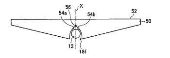
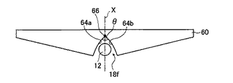
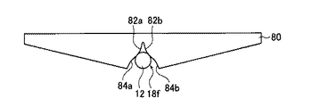
ここで、前記矩形状光射出面の前記第1部分の相対照度又は相対輝度のピーク値が、前記第2部分の相対照度又は相対輝度の平均値の3倍以下となるように、前記平行溝の先端部分を対称に細くするのが好ましい。
また、前記平行溝の断面形状において、前記先端部分は、前記棒状光源の中心から前記矩形状光射出面に向かう垂線に対する角度が、両側で90度以内となる部分であるのが好ましい。
また、前記平行溝の断面形状において、前記先端部分は、前記棒状光源の中心から前記矩形状光射出面に向かう垂線に対する角度が、両側で60度以内となる部分であるのが好ましい。また、前記角度は、導光板の厚みや棒状光源の配置を考えた場合に、実質的に20度以上であることが好ましい。
また、前記平行溝の少なくとも前記先端部分の断面形状、または、前記平行溝の断面形状が、三角形であるのが好ましい。
また、前記平行溝の少なくとも前記先端部分の断面形状となる前記2つの曲線が、前記平行溝の中心に向かって凸または凹であるのが好ましい。
また、前記平行溝の少なくとも前記先端部分の断面形状、または、前記平行溝の断面形状となる前記2つの曲線が、前記平行溝の中心に向かって凸または凹であって、その形状が10次の関数で近似される曲線であるのが好ましく、その曲線は円、楕円、放物線、または双曲線の一部であるのがより好ましい。
また、前記平行溝の前記先端部分の前記頂部の断面形状が、前記先鋭な1つの交点が面取りされた前記矩形状光射出面に平行な部分を持つ形状であるのが好ましい。
また、前記平行溝の少なくとも前記先端部分の断面形状、または、前記平行溝の断面形状が、三角形であり、前記平行溝の前記先端部分の前記頂部の断面形状が、前記中心線に対して対称な台形状であるのが好ましい。
なお、上記断面形状の説明において、三角形、台形とは、平行溝の断面を形成する線が直線から構成される場合に溝の開放部を直線で補完した場合に見える形状を指すものとする。
また、前記平行溝の前記先端部分の前記頂部の断面形状が、前記中心線に対して対称に前記先鋭な1つの交点が丸められた円形状、楕円形状、放物線状、または双曲線状であるのが好ましい。
また、前記平行溝の前記先端部分の前記頂部が、砂ずり面であるのが好ましい。
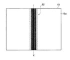
また、前記矩形状光出射面の、前記平行溝の前記先端部分の前記頂部に相当する部分に網点を有するのが好ましい。
ここで、さらに、前記導光板の前記矩形状光出射面と前記拡散シートとの間に配置されるプリズムシートを有するのが好ましい。
また、前記導光板の前記矩形状光射出面の前記第1部分の相対照度又は相対輝度のピーク値の、前記第2部分の相対照度又は相対輝度の平均値に対する比は、前記導光板の前記矩形状光射出面と前記拡散シートとの間に許容される間隔、または面状照明装置に許容される厚み応じて設定されるのが好ましい。
また、本発明の第1の態様の第1の形態によれば、平行溝に相当する光射出面の第1部分において平行溝内に収納された棒状光源からの射出光による照度又は輝度のピーク値の、それ以外の部分の照度又は輝度の平均値との比に応じて、平行溝の断面形状を、光出射面に向かう先端部分に向かって細くしていくことにより、照度又は輝度のピークを低減でき、光射出面における照度又は輝度をより均一化することができ、光射出面に要求される均一度を達成することができる。
また、本発明の第1の態様の第2の形態によれば、光射出面の第1部分の照度又は輝度のピーク値が、それ以外の部分の照度又は輝度の平均値の3倍以下となるように、平行溝の断面形状を、光出射面に向かう先端部分に向かって細くしていくことにより、照度又は輝度のピークを低減でき、光射出面における照度又は輝度をより均一化することができる。
また、本発明の第1の態様の第3の形態によれば、第1または第2の形態の導光板の薄肉端部を互いに連結することにより、導光板の光射出面のサイズを、より大サイズとすることができる。
また、本発明の第3の態様によれば、上記第2の態様の面状照明装置を用いることにより、薄型で軽量であり、より低コストで製造することができ、より均一でむらの少ない、かつより高輝度な表示を行うことができ、また、その表示画面を大サイズとすることができ、あるいは、壁掛けテレビなどの壁掛け型とすることができる液晶表示装置を提供することができる。
本発明において、拡散シート14としては、上記の素材を用い、かつ、光拡散性を付与した厚み500μm以下のフィルム状部材を用いることも好ましい。
特に、バックライトユニット2の厚みを少し厚くしてもよい場合には、導光板18の平行溝18fの断面形状によって、平行溝18fに相当する導光板18の光射出面18aにおける照度のピーク値を十分に低減する必要はなく、部分的に低減するとともに拡散シート14と導光板18の光射出面18aとの間に間隙を設けて、拡散シート14から射出される照明光を照度分布を均一にしても良い。また、導光板18の平行溝18fの断面形状の改良(平行溝の先端部分の先細化)に限界があり、平行溝18fに相当する導光板18の光射出面18aにおける照度のピーク値を完全に低減できない場合や十分に低減できない場合にも、拡散シート14と導光板18の光射出面18aとの間に間隙を設けて、拡散シート14から射出される照明光の照度分布を均一にしても良い。
なお、図示例においては、プリズムシート16および17、さらに好ましくはプリズムシート19を用いているが、導光板18の平行溝18fによる光射出面18aにおける照度がより均一化されている場合には、プリズムシート19はもちろん不要であるし、プリズムシート16および17のどちらか一方、または両方を用いなくても良い。高価なプリズムシートの使用枚数を減らし、あるいは、プリズムシートの使用をやめることにより、装置コストを低減させることができる。
本発明の導光板に光源を組み込み、導光板内に光を入射して光出射面より光が出射するようにした状態で、XYステージに固定し、導光板の出射面に垂直になるように照度計を固定する。そして照度計によって光出射面の位置における照度を測定して導光板の光出射面の特定位置に関する、照度の情報を得る。
その後、XYステージを移動させることにより、光出射面上の位置と照度の関係を求めて、その全面の平均値を算出する。各位置における照度をこの照度の平均値をそれぞれ割り返した比率が、その位置における相対照度となる。
なお、平行溝の軸方向に垂直な方向1軸を測定してその値を代表させることで、断面形状の比較等を簡便に行うこともできる。
なお、相対輝度を測定する場合には、照度計の代わりに輝度計を用いればよく、これにより、導光板の光出射側の面における相対輝度分布を得ることができる。
導光板の表面において、照度と輝度は略同様に扱うことができる。それゆえ、図11及び13の相対照度のグラフから、本発明においては、輝度においても同様の傾向があると推測される。したがって、導光板の平行溝の形状を本発明で示した形状になるように設計することで、導光板の光射出面における輝度についても均一化できると考えられる。
なお、平行溝の先端部分の頂部(最深部)の断面形状が、平行溝の中心線に対して対称に先鋭な1つの交点が、面取りされた平坦状、もしくは、丸められた円形状のみならず、楕円形状、放物線状、または双曲線状であっても良いのはもちろんである。さらに、これに加え、上述したように、平行溝の先端部分の頂部(最深部)を砂擦り面とすることにより、照度又は輝度のピーク値を低減するようにしても良い。
このような大サイズの光射出面を持つ導光板を用いることにより、大サイズの光照射面を持つバックライトユニットとすることができるので、大サイズの表示画面を持つ液晶表示装置に適用することができ、特に、壁掛けテレビなどの壁掛けタイプの液晶表示装置に適用することができる。
製造効率の観点からは、必要な画面サイズに相当する導光板を形成するのに必要な数の本発明の導光板ユニットを一体で成形することが好ましい。
4 液晶表示パネル
6 駆動ユニット
10 液晶表示装置
12 光源
14 拡散シート
16、17、19 プリズムシート
18、50、60、70、80、100 導光板
18a、52 光射出面
18b 厚肉部
18c 薄肉端部
18d 傾斜面
18e 傾斜背面部
18f 平行溝
20 リフレクタ
22 反射シート
24 反射板
54a、54b 円弧曲線
56 交点
64a、64b 放物線
72a、72b、82a、82b、84a、84b 曲線
92 網点パターン
Claims (17)
- 矩形状光射出面と、
その一辺に平行で矩形状略中央部に位置する厚肉部と、
前記厚肉部に平行に形成される薄肉端部と、
棒状光源を収納するための平行溝が、前記厚肉部の略中央に前記一辺と平行に形成されており、
前記平行溝の両側に前記棒状光源の軸を含み矩形状光出射面に対して垂直な面に対して対称であり、
前記厚肉部から前記一辺に直交する方向に両側の前記薄肉端部に向かって肉厚が薄くなり、
傾斜背面を形成する傾斜背面部と、を有する透明な導光板であって、
前記矩形状光射出面の前記平行溝に相当する第1部分において前記平行溝に収納された棒状光源からの射出光によって形成される照度又は輝度のピーク値が、前記傾斜背面部に相当する第2部分において前記射出光によって形成される照度又は輝度の平均値の3倍以下となるように、前記平行溝の前記直交方向の断面形状において、前記平行溝の前記矩形状光射出面に垂直な中心線に対して、前記矩形状光射出面に向かって前記平行溝の先端部分を対称に細くしており、
前記平行溝の少なくとも前記先端部分の断面形状が、互いに交わる先鋭な1つの交点を持つ、前記中心線に対して対称な2つの曲線の一部からなるか、または前記平行溝の中心に向かって凸または凹の、円、楕円、放物線または双曲線の一部からなることを特徴とする導光板。 - 前記矩形状光射出面の前記第1部分の相対照度又は相対輝度のピークは、前記第2部分の相対照度又は相対輝度の平均値の2倍以下である請求項1に記載の導光板。
- 前記平行溝の断面形状において、前記先端部分は、前記棒状光源の中心から前記矩形状光射出面に向かう垂線に対する角度が、両側で90度以内となる部分である請求項1または2に記載の導光板。
- 前記平行溝の断面形状において、前記先端部分は、前記棒状光源の中心から前記矩形状光射出面に向かう垂線に対する角度が、両側で60度以内となる部分である請求項1〜3のいずれかに記載の導光板。
- 前記平行溝の少なくとも前記先端部分の断面形状となる前記2つの曲線が、前記平行溝の中心に向かって凸または凹である請求項1〜4のいずれかに記載の導光板。
- 前記平行溝の少なくとも前記先端部分の断面形状となる前記2つの曲線が10次関数で近似でき、前記平行溝の中心に向かって凸または凹である請求項1〜5のいずれかに記載の導光板。
- 前記平行溝の前記先端部分の頂部の断面形状が、前記対称な2つの曲線が交わる前に互いに前記中心線に対して対称な直線または曲線で接続された形状である請求項1〜6のいずれかに記載の導光板。
- 前記中心線に対して対称な2つの曲線が、円弧である場合、それぞれの円弧の中心の位置が異なる請求項1に記載の導光板。
- 前記中心線に対して対称な2つの曲線が、放物線である場合、それぞれの放物線の中心の位置が異なる請求項1に記載の導光板。
- 前記平行溝の前記先端部分の頂部の断面形状が前記中心線に対して凸の曲線であり、前記中心線に対して対称な2つの曲線が、前記平行溝の中心に向かって凹の曲線である請求項7に記載の導光板。
- 前記平行溝の前記先端部分の頂部が、砂ずり面である請求項1〜10のいずれかに記載の導光板。
- 前記矩形状光出射面の、前記平行溝の前記先端部分の頂部に相当する部分に網点を有するか、または砂ずり面が形成されている請求項1〜10のいずれかに記載の導光板。
- 複数個の、請求項1〜12のいずれかに記載の導光板からなり、その前記薄肉端面が互いに連結されていることを特徴とする導光板。
- 請求項1〜13のいずれかに記載の導光板と、
前記導光板の前記平行溝に収納される棒状光源と、
前記平行溝を塞ぐように前記棒状光源を背後に設けられるリフレクタと、
前記導光板の前記厚肉部の両側の前記傾斜背面部の前記傾斜背面に取り付けられる反射シートと、
前記導光板の前記矩形状光出射面上に配置される拡散シートとを有することを特徴とする面状照明装置。 - さらに、前記導光板の前記矩形状光出射面と前記拡散シートとの間に配置されるプリズムシートを有することを特徴とする請求項14に記載の面状照明装置。
- 前記導光板の前記矩形状光射出面の前記第1部分の相対照度又は相対輝度のピーク値の、前記第2部分の相対照度又は相対輝度の平均値に対する比は、前記導光板の前記矩形状光射出面と前記拡散シートとの間に許容される間隔、または面状照明装置に許容される厚み応じて設定される請求項14または15に記載の面状照明装置。
- 請求項14〜16のいずれかに記載の面状照明装置からなるバックライトユニットと、
このバックライトユニットの光出射面側に配置される液晶表示パネルと、前記バックライトユニットおよび前記液晶表示パネルを駆動する駆動ユニットとを有することを特徴とする液晶表示装置。
Priority Applications (6)
| Application Number | Priority Date | Filing Date | Title |
|---|---|---|---|
| JP2004045463A JP4264013B2 (ja) | 2004-02-20 | 2004-02-20 | 導光板、これを用いる面状照明装置および液晶表示装置 |
| PCT/JP2005/003087 WO2005080863A2 (en) | 2004-02-20 | 2005-02-18 | Light guide plate, and planar lighting device and liquid crystal display device using the same |
| EP05710687A EP1716438A2 (en) | 2004-02-20 | 2005-02-18 | Light guide plate, and planar lighting device and liquid crystal display device using the same |
| TW094104747A TW200537204A (en) | 2004-02-20 | 2005-02-18 | Light guide plate, and planar lighting device and liquid crystal display device using the same |
| US10/588,935 US8210731B2 (en) | 2004-02-20 | 2005-02-18 | Light guide plate, and planar lighting device and liquid crystal display device using the same |
| CNA2005800053385A CN1922515A (zh) | 2004-02-20 | 2005-02-18 | 光导板和使用该光导板的平面照明装置、液晶显示装置 |
Applications Claiming Priority (1)
| Application Number | Priority Date | Filing Date | Title |
|---|---|---|---|
| JP2004045463A JP4264013B2 (ja) | 2004-02-20 | 2004-02-20 | 導光板、これを用いる面状照明装置および液晶表示装置 |
Publications (3)
| Publication Number | Publication Date |
|---|---|
| JP2005234397A JP2005234397A (ja) | 2005-09-02 |
| JP2005234397A5 JP2005234397A5 (ja) | 2006-06-29 |
| JP4264013B2 true JP4264013B2 (ja) | 2009-05-13 |
Family
ID=34879390
Family Applications (1)
| Application Number | Title | Priority Date | Filing Date |
|---|---|---|---|
| JP2004045463A Expired - Lifetime JP4264013B2 (ja) | 2004-02-20 | 2004-02-20 | 導光板、これを用いる面状照明装置および液晶表示装置 |
Country Status (6)
| Country | Link |
|---|---|
| US (1) | US8210731B2 (ja) |
| EP (1) | EP1716438A2 (ja) |
| JP (1) | JP4264013B2 (ja) |
| CN (1) | CN1922515A (ja) |
| TW (1) | TW200537204A (ja) |
| WO (1) | WO2005080863A2 (ja) |
Families Citing this family (35)
| Publication number | Priority date | Publication date | Assignee | Title |
|---|---|---|---|---|
| JP4855944B2 (ja) * | 2004-11-09 | 2012-01-18 | 富士フイルム株式会社 | 連結導光板、これを用いる面状照明装置および液晶表示装置 |
| EP1847767A4 (en) * | 2005-02-08 | 2013-01-23 | Fujifilm Corp | LIGHT GUIDE PLATE, AND PLANAR LIGHTING DEVICE AND LIQUID CRYSTAL DISPLAY DEVICE USING THE LIGHT GUIDE PLATE |
| JP4814221B2 (ja) * | 2005-03-29 | 2011-11-16 | 富士フイルム株式会社 | 導光部材及びそれを用いた面状照明装置、並びに棒状照明装置 |
| JP2006339320A (ja) * | 2005-05-31 | 2006-12-14 | Omron Corp | 発光光源及び発光光源における光の出射方法 |
| US7760403B2 (en) * | 2005-06-14 | 2010-07-20 | Ricoh Co., Ltd. | Optical irradiation apparatus, image reading apparatus using the same, and image forming apparatus using the same |
| US20080212315A1 (en) * | 2005-09-19 | 2008-09-04 | Koninklijke Philips Electronics, N.V. | Illumination System for Illumination Display Devices, and Display Device Provided with Such an Illumination System |
| JP2007155791A (ja) | 2005-11-30 | 2007-06-21 | Fujifilm Corp | 面光源装置 |
| US7445358B2 (en) | 2005-12-27 | 2008-11-04 | Fujifilm Corporation | Light guide plate and a planar lighting device using the same |
| JP4629585B2 (ja) * | 2006-01-17 | 2011-02-09 | 富士フイルム株式会社 | 導光板およびこれを用いる面状照明装置 |
| JP4648209B2 (ja) * | 2006-02-02 | 2011-03-09 | 富士フイルム株式会社 | 面状照明装置 |
| JP4524255B2 (ja) * | 2006-02-07 | 2010-08-11 | 富士フイルム株式会社 | 面状照明装置 |
| JP4652987B2 (ja) * | 2006-02-09 | 2011-03-16 | 富士フイルム株式会社 | 面状照明装置 |
| CN100543549C (zh) * | 2006-03-22 | 2009-09-23 | 鸿富锦精密工业(深圳)有限公司 | 背光系统 |
| JP4699936B2 (ja) * | 2006-04-28 | 2011-06-15 | 富士フイルム株式会社 | 面状照明装置およびこれを用いる液晶表示装置 |
| JP4155310B2 (ja) * | 2006-06-02 | 2008-09-24 | ソニー株式会社 | バックライト装置と液晶表示装置および液晶表示装置を使用した電子機器 |
| KR20090084830A (ko) | 2006-09-29 | 2009-08-05 | 오스람 옵토 세미컨덕터스 게엠베하 | 광 도파로 및 광학 장치 |
| US7746517B2 (en) * | 2007-01-25 | 2010-06-29 | Lexmark International, Inc. | Image illumination and capture in a scanning device |
| JP5153152B2 (ja) | 2007-01-31 | 2013-02-27 | 富士フイルム株式会社 | 面状照明装置 |
| JP5414224B2 (ja) | 2007-10-19 | 2014-02-12 | 富士フイルム株式会社 | 面状照明装置 |
| JP2010080401A (ja) | 2008-09-29 | 2010-04-08 | Fujifilm Corp | 面状照明装置 |
| US20120155110A1 (en) * | 2009-09-23 | 2012-06-21 | Koninklijke Philips Electronics N.V. | Light guide, illumination system, backlighting system and display device |
| CN101980059B (zh) * | 2010-08-30 | 2012-12-19 | 应骏 | 一种透光面板及其显示图像的矫正方法 |
| CN102156320B (zh) * | 2011-02-25 | 2013-06-26 | 深圳市华星光电技术有限公司 | 侧入式导光板组件及背光模块 |
| KR101859413B1 (ko) * | 2011-12-26 | 2018-05-21 | 삼성디스플레이 주식회사 | 표시 모듈 및 이를 포함하는 표시 장치 |
| US9052544B2 (en) * | 2012-03-26 | 2015-06-09 | Shenzhen China Star Optoelectronics Technology Co., Ltd | Direct-light backlight module and liquid crystal display device |
| KR102232058B1 (ko) * | 2012-09-19 | 2021-03-24 | 엘지디스플레이 주식회사 | 백라이트 유닛 및 이를 포함하는 액정표시장치 모듈 |
| TWI490607B (zh) * | 2012-10-15 | 2015-07-01 | 群康科技(深圳)有限公司 | 顯示裝置及其發光模組與導光板 |
| TWI485483B (zh) * | 2012-10-16 | 2015-05-21 | Innocom Tech Shenzhen Co Ltd | 導光板、發光模組及顯示裝置 |
| US9784902B2 (en) * | 2013-03-25 | 2017-10-10 | 3M Innovative Properties Company | Dual-sided film with split light spreading structures |
| EP3362736A4 (en) * | 2015-10-13 | 2019-03-13 | Ameritech LLC | LUMINAIRE CONTAINING LIGHT EMITTING DIODES |
| US10739513B2 (en) | 2018-08-31 | 2020-08-11 | RAB Lighting Inc. | Apparatuses and methods for efficiently directing light toward and away from a mounting surface |
| US10801679B2 (en) | 2018-10-08 | 2020-10-13 | RAB Lighting Inc. | Apparatuses and methods for assembling luminaires |
| JP7382563B2 (ja) * | 2019-05-23 | 2023-11-17 | パナソニックIpマネジメント株式会社 | 照明器具 |
| JP7204304B2 (ja) * | 2019-07-31 | 2023-01-16 | 矢崎総業株式会社 | 指針発光装置 |
| CN112310056B (zh) * | 2019-08-02 | 2024-06-18 | 日亚化学工业株式会社 | 发光装置和面发光光源 |
Family Cites Families (13)
| Publication number | Priority date | Publication date | Assignee | Title |
|---|---|---|---|---|
| US5034864A (en) * | 1989-04-25 | 1991-07-23 | Mitsubishi Rayon Co., Ltd. | Planar light-source device and illumination apparatus using the same |
| JPH05249320A (ja) * | 1992-03-04 | 1993-09-28 | Nisshin Hightech Kk | 面照明用光導波装置 |
| JPH071428U (ja) * | 1993-06-04 | 1995-01-10 | 株式会社エンプラス | 面光源装置 |
| JPH08271886A (ja) | 1995-03-29 | 1996-10-18 | Toshiba Corp | 面光源装置およびそれを用いた表示装置 |
| JPH0862426A (ja) * | 1994-08-16 | 1996-03-08 | Nec Corp | 液晶表示装置のバックライト |
| JP3603462B2 (ja) * | 1996-03-28 | 2004-12-22 | セイコーエプソン株式会社 | バックライトの駆動装置および駆動方法 |
| JP3319945B2 (ja) * | 1996-05-13 | 2002-09-03 | 株式会社エンプラス | 面光源装置 |
| JP3427636B2 (ja) * | 1996-09-06 | 2003-07-22 | オムロン株式会社 | 面光源装置及び液晶表示装置 |
| JP3841893B2 (ja) * | 1996-11-05 | 2006-11-08 | 三菱電機株式会社 | バックライトユニット及びこれを用いた液晶表示装置 |
| JPH11149073A (ja) * | 1997-11-18 | 1999-06-02 | Matsushita Electric Ind Co Ltd | 面光源装置および液晶表示装置 |
| US6865325B2 (en) * | 2001-04-19 | 2005-03-08 | International Business Machines Corporation | Discrete pattern, apparatus, method, and program storage device for generating and implementing the discrete pattern |
| US6923554B2 (en) * | 2003-02-17 | 2005-08-02 | Heng Sheng Kuo | Backlight module |
| JP2004302067A (ja) * | 2003-03-31 | 2004-10-28 | Toyota Industries Corp | 導光板、照明装置及び液晶表示装置 |
-
2004
- 2004-02-20 JP JP2004045463A patent/JP4264013B2/ja not_active Expired - Lifetime
-
2005
- 2005-02-18 TW TW094104747A patent/TW200537204A/zh unknown
- 2005-02-18 US US10/588,935 patent/US8210731B2/en active Active
- 2005-02-18 EP EP05710687A patent/EP1716438A2/en not_active Withdrawn
- 2005-02-18 WO PCT/JP2005/003087 patent/WO2005080863A2/en not_active Application Discontinuation
- 2005-02-18 CN CNA2005800053385A patent/CN1922515A/zh active Pending
Also Published As
| Publication number | Publication date |
|---|---|
| US8210731B2 (en) | 2012-07-03 |
| WO2005080863A3 (en) | 2006-02-02 |
| WO2005080863A2 (en) | 2005-09-01 |
| TW200537204A (en) | 2005-11-16 |
| US20070165422A1 (en) | 2007-07-19 |
| JP2005234397A (ja) | 2005-09-02 |
| CN1922515A (zh) | 2007-02-28 |
| EP1716438A2 (en) | 2006-11-02 |
Similar Documents
| Publication | Publication Date | Title |
|---|---|---|
| JP4264013B2 (ja) | 導光板、これを用いる面状照明装置および液晶表示装置 | |
| JP4855944B2 (ja) | 連結導光板、これを用いる面状照明装置および液晶表示装置 | |
| JP4607648B2 (ja) | 導光板、これを備える面状照明装置および液晶表示装置 | |
| US7556391B2 (en) | Transmittance adjuster unit, a planar illumination device, a liquid crystal display device using the same, and a method of arranging transmittance adjusters | |
| KR100428829B1 (ko) | 광학유닛, 도광판 및 액정표시장치 | |
| JP4436105B2 (ja) | リフレクタ及び照明装置及び導光板及び表示装置 | |
| JP4814221B2 (ja) | 導光部材及びそれを用いた面状照明装置、並びに棒状照明装置 | |
| WO2006004160A1 (ja) | 導光部材及びそれを用いた面状照明装置並びに棒状照明装置 | |
| JP2009135116A (ja) | 面光源装置、プリズムシート、表示装置及び情報処理装置 | |
| JP4542478B2 (ja) | 導光板、これを用いる面状照明装置および液晶表示装置 | |
| JP4555249B2 (ja) | 透過率調整体ユニット、これを用いる面状照明装置及び液晶表示装置 | |
| JP2005085671A (ja) | 導光板及び面光源装置 | |
| JP2006301518A (ja) | 導光板、これを用いる面状照明装置および液晶表示装置 | |
| JP4750679B2 (ja) | 面状照明装置及び液晶表示装置 | |
| JP4546360B2 (ja) | 透過率調整体ユニット、これを用いる面状照明装置及び液晶表示装置 | |
| JP4963726B2 (ja) | 面状照明装置および液晶表示装置 | |
| JP2007027044A (ja) | 導光板、これを備える面状照明装置および液晶表示装置 | |
| JP2012204323A (ja) | 面状照明装置 | |
| JP2006318754A (ja) | 透過率調整体ユニット、面状照明装置、およびそれを用いる液晶表示装置 | |
| WO2005121639A1 (ja) | 導光板、これを用いる面状照明装置及び液晶表示装置 | |
| WO2005121638A1 (ja) | 導光板、これを用いる面状照明装置および液晶表示装置 | |
| JP2006339043A (ja) | 面状照明装置及びそれを備える液晶表示装置 | |
| WO2005114046A1 (ja) | 導光板、これを用いる面状照明装置および液晶表示装置 | |
| JP2004319399A (ja) | 導光ブロックおよび平面照明装置 |
Legal Events
| Date | Code | Title | Description |
|---|---|---|---|
| A521 | Request for written amendment filed |
Free format text: JAPANESE INTERMEDIATE CODE: A523 Effective date: 20060512 |
|
| A621 | Written request for application examination |
Free format text: JAPANESE INTERMEDIATE CODE: A621 Effective date: 20060512 |
|
| A711 | Notification of change in applicant |
Free format text: JAPANESE INTERMEDIATE CODE: A712 Effective date: 20061206 |
|
| RD04 | Notification of resignation of power of attorney |
Free format text: JAPANESE INTERMEDIATE CODE: A7424 Effective date: 20080711 |
|
| A131 | Notification of reasons for refusal |
Free format text: JAPANESE INTERMEDIATE CODE: A131 Effective date: 20080902 |
|
| A521 | Request for written amendment filed |
Free format text: JAPANESE INTERMEDIATE CODE: A523 Effective date: 20081104 |
|
| A131 | Notification of reasons for refusal |
Free format text: JAPANESE INTERMEDIATE CODE: A131 Effective date: 20081125 |
|
| A521 | Request for written amendment filed |
Free format text: JAPANESE INTERMEDIATE CODE: A523 Effective date: 20090113 |
|
| TRDD | Decision of grant or rejection written | ||
| A01 | Written decision to grant a patent or to grant a registration (utility model) |
Free format text: JAPANESE INTERMEDIATE CODE: A01 Effective date: 20090203 |
|
| A01 | Written decision to grant a patent or to grant a registration (utility model) |
Free format text: JAPANESE INTERMEDIATE CODE: A01 |
|
| A61 | First payment of annual fees (during grant procedure) |
Free format text: JAPANESE INTERMEDIATE CODE: A61 Effective date: 20090213 |
|
| FPAY | Renewal fee payment (event date is renewal date of database) |
Free format text: PAYMENT UNTIL: 20120220 Year of fee payment: 3 |
|
| R150 | Certificate of patent or registration of utility model |
Free format text: JAPANESE INTERMEDIATE CODE: R150 Ref document number: 4264013 Country of ref document: JP Free format text: JAPANESE INTERMEDIATE CODE: R150 |
|
| FPAY | Renewal fee payment (event date is renewal date of database) |
Free format text: PAYMENT UNTIL: 20120220 Year of fee payment: 3 |
|
| FPAY | Renewal fee payment (event date is renewal date of database) |
Free format text: PAYMENT UNTIL: 20130220 Year of fee payment: 4 |
|
| R250 | Receipt of annual fees |
Free format text: JAPANESE INTERMEDIATE CODE: R250 |
|
| FPAY | Renewal fee payment (event date is renewal date of database) |
Free format text: PAYMENT UNTIL: 20140220 Year of fee payment: 5 |
|
| R250 | Receipt of annual fees |
Free format text: JAPANESE INTERMEDIATE CODE: R250 |
|
| R250 | Receipt of annual fees |
Free format text: JAPANESE INTERMEDIATE CODE: R250 |
|
| R250 | Receipt of annual fees |
Free format text: JAPANESE INTERMEDIATE CODE: R250 |
|
| R250 | Receipt of annual fees |
Free format text: JAPANESE INTERMEDIATE CODE: R250 |
|
| R250 | Receipt of annual fees |
Free format text: JAPANESE INTERMEDIATE CODE: R250 |
|
| R250 | Receipt of annual fees |
Free format text: JAPANESE INTERMEDIATE CODE: R250 |
|
| R250 | Receipt of annual fees |
Free format text: JAPANESE INTERMEDIATE CODE: R250 |
|
| R250 | Receipt of annual fees |
Free format text: JAPANESE INTERMEDIATE CODE: R250 |
|
| R250 | Receipt of annual fees |
Free format text: JAPANESE INTERMEDIATE CODE: R250 |
|
| R250 | Receipt of annual fees |
Free format text: JAPANESE INTERMEDIATE CODE: R250 |
|
| R250 | Receipt of annual fees |
Free format text: JAPANESE INTERMEDIATE CODE: R250 |
|
| EXPY | Cancellation because of completion of term |


