JP4264013B2 - Light guide plate, planar illumination device using the same, and liquid crystal display device - Google Patents
Light guide plate, planar illumination device using the same, and liquid crystal display device Download PDFInfo
- Publication number
- JP4264013B2 JP4264013B2 JP2004045463A JP2004045463A JP4264013B2 JP 4264013 B2 JP4264013 B2 JP 4264013B2 JP 2004045463 A JP2004045463 A JP 2004045463A JP 2004045463 A JP2004045463 A JP 2004045463A JP 4264013 B2 JP4264013 B2 JP 4264013B2
- Authority
- JP
- Japan
- Prior art keywords
- guide plate
- light
- light guide
- parallel groove
- parallel
- Prior art date
- Legal status (The legal status is an assumption and is not a legal conclusion. Google has not performed a legal analysis and makes no representation as to the accuracy of the status listed.)
- Expired - Lifetime
Links
- 238000005286 illumination Methods 0.000 title claims description 44
- 239000004973 liquid crystal related substance Substances 0.000 title claims description 37
- 238000009792 diffusion process Methods 0.000 claims description 41
- 230000007423 decrease Effects 0.000 claims description 5
- 239000004576 sand Substances 0.000 claims description 3
- 238000012886 linear function Methods 0.000 claims 1
- 239000010802 sludge Substances 0.000 claims 1
- 239000011347 resin Substances 0.000 description 14
- 229920005989 resin Polymers 0.000 description 14
- 238000009826 distribution Methods 0.000 description 12
- 238000012937 correction Methods 0.000 description 8
- 230000003287 optical effect Effects 0.000 description 7
- 239000004743 Polypropylene Substances 0.000 description 6
- 239000000463 material Substances 0.000 description 6
- 230000000694 effects Effects 0.000 description 5
- 229910052751 metal Inorganic materials 0.000 description 5
- 239000002184 metal Substances 0.000 description 5
- 238000000034 method Methods 0.000 description 5
- -1 polyethylene terephthalate Polymers 0.000 description 5
- 229920000139 polyethylene terephthalate Polymers 0.000 description 5
- 239000005020 polyethylene terephthalate Substances 0.000 description 5
- 229920003229 poly(methyl methacrylate) Polymers 0.000 description 4
- 239000004417 polycarbonate Substances 0.000 description 4
- 239000004926 polymethyl methacrylate Substances 0.000 description 4
- VYPSYNLAJGMNEJ-UHFFFAOYSA-N Silicium dioxide Chemical compound O=[Si]=O VYPSYNLAJGMNEJ-UHFFFAOYSA-N 0.000 description 3
- 239000010419 fine particle Substances 0.000 description 3
- 239000011888 foil Substances 0.000 description 3
- 229920001155 polypropylene Polymers 0.000 description 3
- 238000002310 reflectometry Methods 0.000 description 3
- 239000004925 Acrylic resin Substances 0.000 description 2
- 229920000178 Acrylic resin Polymers 0.000 description 2
- XLOMVQKBTHCTTD-UHFFFAOYSA-N Zinc monoxide Chemical compound [Zn]=O XLOMVQKBTHCTTD-UHFFFAOYSA-N 0.000 description 2
- MCMNRKCIXSYSNV-UHFFFAOYSA-N Zirconium dioxide Chemical compound O=[Zr]=O MCMNRKCIXSYSNV-UHFFFAOYSA-N 0.000 description 2
- 229910052782 aluminium Inorganic materials 0.000 description 2
- XAGFODPZIPBFFR-UHFFFAOYSA-N aluminium Chemical compound [Al] XAGFODPZIPBFFR-UHFFFAOYSA-N 0.000 description 2
- 239000011324 bead Substances 0.000 description 2
- AOJOEFVRHOZDFN-UHFFFAOYSA-N benzyl 2-methylprop-2-enoate Chemical compound CC(=C)C(=O)OCC1=CC=CC=C1 AOJOEFVRHOZDFN-UHFFFAOYSA-N 0.000 description 2
- 238000013461 design Methods 0.000 description 2
- 238000004898 kneading Methods 0.000 description 2
- 238000004519 manufacturing process Methods 0.000 description 2
- 239000000049 pigment Substances 0.000 description 2
- 229920000515 polycarbonate Polymers 0.000 description 2
- 229920000089 Cyclic olefin copolymer Polymers 0.000 description 1
- GWEVSGVZZGPLCZ-UHFFFAOYSA-N Titan oxide Chemical compound O=[Ti]=O GWEVSGVZZGPLCZ-UHFFFAOYSA-N 0.000 description 1
- 239000011230 binding agent Substances 0.000 description 1
- 238000005266 casting Methods 0.000 description 1
- 239000011248 coating agent Substances 0.000 description 1
- 238000000576 coating method Methods 0.000 description 1
- 150000001925 cycloalkenes Chemical class 0.000 description 1
- 238000001125 extrusion Methods 0.000 description 1
- 239000000945 filler Substances 0.000 description 1
- 239000011521 glass Substances 0.000 description 1
- 238000001746 injection moulding Methods 0.000 description 1
- 230000001678 irradiating effect Effects 0.000 description 1
- 239000000178 monomer Substances 0.000 description 1
- 238000005498 polishing Methods 0.000 description 1
- 229920000642 polymer Polymers 0.000 description 1
- 238000006116 polymerization reaction Methods 0.000 description 1
- 238000012545 processing Methods 0.000 description 1
- 230000001737 promoting effect Effects 0.000 description 1
- 239000002994 raw material Substances 0.000 description 1
- 238000011160 research Methods 0.000 description 1
- 238000007788 roughening Methods 0.000 description 1
- 239000000377 silicon dioxide Substances 0.000 description 1
- 125000006850 spacer group Chemical group 0.000 description 1
- OGIDPMRJRNCKJF-UHFFFAOYSA-N titanium oxide Inorganic materials [Ti]=O OGIDPMRJRNCKJF-UHFFFAOYSA-N 0.000 description 1
- 238000007740 vapor deposition Methods 0.000 description 1
- 239000013585 weight reducing agent Substances 0.000 description 1
- 239000011787 zinc oxide Substances 0.000 description 1
Images


Classifications
-
- G—PHYSICS
- G02—OPTICS
- G02B—OPTICAL ELEMENTS, SYSTEMS OR APPARATUS
- G02B6/00—Light guides; Structural details of arrangements comprising light guides and other optical elements, e.g. couplings
- G02B6/0001—Light guides; Structural details of arrangements comprising light guides and other optical elements, e.g. couplings specially adapted for lighting devices or systems
- G02B6/0011—Light guides; Structural details of arrangements comprising light guides and other optical elements, e.g. couplings specially adapted for lighting devices or systems the light guides being planar or of plate-like form
- G02B6/0033—Means for improving the coupling-out of light from the light guide
- G02B6/0035—Means for improving the coupling-out of light from the light guide provided on the surface of the light guide or in the bulk of it
- G02B6/0045—Means for improving the coupling-out of light from the light guide provided on the surface of the light guide or in the bulk of it by shaping at least a portion of the light guide
- G02B6/0046—Tapered light guide, e.g. wedge-shaped light guide
-
- G—PHYSICS
- G02—OPTICS
- G02B—OPTICAL ELEMENTS, SYSTEMS OR APPARATUS
- G02B6/00—Light guides; Structural details of arrangements comprising light guides and other optical elements, e.g. couplings
- G02B6/0001—Light guides; Structural details of arrangements comprising light guides and other optical elements, e.g. couplings specially adapted for lighting devices or systems
- G02B6/0011—Light guides; Structural details of arrangements comprising light guides and other optical elements, e.g. couplings specially adapted for lighting devices or systems the light guides being planar or of plate-like form
- G02B6/0013—Means for improving the coupling-in of light from the light source into the light guide
- G02B6/0015—Means for improving the coupling-in of light from the light source into the light guide provided on the surface of the light guide or in the bulk of it
- G02B6/002—Means for improving the coupling-in of light from the light source into the light guide provided on the surface of the light guide or in the bulk of it by shaping at least a portion of the light guide, e.g. with collimating, focussing or diverging surfaces
- G02B6/0021—Means for improving the coupling-in of light from the light source into the light guide provided on the surface of the light guide or in the bulk of it by shaping at least a portion of the light guide, e.g. with collimating, focussing or diverging surfaces for housing at least a part of the light source, e.g. by forming holes or recesses
-
- G—PHYSICS
- G02—OPTICS
- G02B—OPTICAL ELEMENTS, SYSTEMS OR APPARATUS
- G02B6/00—Light guides; Structural details of arrangements comprising light guides and other optical elements, e.g. couplings
- G02B6/0001—Light guides; Structural details of arrangements comprising light guides and other optical elements, e.g. couplings specially adapted for lighting devices or systems
- G02B6/0011—Light guides; Structural details of arrangements comprising light guides and other optical elements, e.g. couplings specially adapted for lighting devices or systems the light guides being planar or of plate-like form
- G02B6/0033—Means for improving the coupling-out of light from the light guide
- G02B6/005—Means for improving the coupling-out of light from the light guide provided by one optical element, or plurality thereof, placed on the light output side of the light guide
- G02B6/0051—Diffusing sheet or layer
-
- G—PHYSICS
- G02—OPTICS
- G02B—OPTICAL ELEMENTS, SYSTEMS OR APPARATUS
- G02B6/00—Light guides; Structural details of arrangements comprising light guides and other optical elements, e.g. couplings
- G02B6/0001—Light guides; Structural details of arrangements comprising light guides and other optical elements, e.g. couplings specially adapted for lighting devices or systems
- G02B6/0011—Light guides; Structural details of arrangements comprising light guides and other optical elements, e.g. couplings specially adapted for lighting devices or systems the light guides being planar or of plate-like form
- G02B6/0033—Means for improving the coupling-out of light from the light guide
- G02B6/005—Means for improving the coupling-out of light from the light guide provided by one optical element, or plurality thereof, placed on the light output side of the light guide
- G02B6/0053—Prismatic sheet or layer; Brightness enhancement element, sheet or layer
-
- G—PHYSICS
- G02—OPTICS
- G02B—OPTICAL ELEMENTS, SYSTEMS OR APPARATUS
- G02B6/00—Light guides; Structural details of arrangements comprising light guides and other optical elements, e.g. couplings
- G02B6/0001—Light guides; Structural details of arrangements comprising light guides and other optical elements, e.g. couplings specially adapted for lighting devices or systems
- G02B6/0011—Light guides; Structural details of arrangements comprising light guides and other optical elements, e.g. couplings specially adapted for lighting devices or systems the light guides being planar or of plate-like form
- G02B6/0033—Means for improving the coupling-out of light from the light guide
- G02B6/005—Means for improving the coupling-out of light from the light guide provided by one optical element, or plurality thereof, placed on the light output side of the light guide
- G02B6/0055—Reflecting element, sheet or layer
Landscapes
- Physics & Mathematics (AREA)
- General Physics & Mathematics (AREA)
- Optics & Photonics (AREA)
- Planar Illumination Modules (AREA)
- Light Guides In General And Applications Therefor (AREA)
- Liquid Crystal (AREA)
Description
本発明は、棒状光源から入射した光を面方向に拡散して光出射面からより均一な照明光を出射する透明な導光板、これを用いる面状照明装置および液晶表示装置に関する。 The present invention relates to a transparent light guide plate that diffuses light incident from a rod-shaped light source in a plane direction and emits more uniform illumination light from a light exit surface, and a planar illumination device and a liquid crystal display device using the same.
液晶表示装置には、液晶パネル(LCD)の裏面側から光を照射し、液晶パネルを照明するバックライトユニットが用いられている。バックライトユニットは、照明用の光源、この光源から出射した光を拡散して液晶パネルを照射する導光板、導光板から放射される光を均一化するプリズムシートや拡散シートなどの部品を用いて構成される。
近年、液晶表示装置の薄型化、低消費電力化が要望されており、それを実現するために種々の形状の導光板が提案されている(特許文献1、特許文献2、特許文献3および特許文献4参照)。
A liquid crystal display device uses a backlight unit that irradiates light from the back side of a liquid crystal panel (LCD) to illuminate the liquid crystal panel. The backlight unit uses a light source for illumination, a light guide plate that diffuses light emitted from the light source and irradiates the liquid crystal panel, and a component such as a prism sheet and a diffusion sheet that uniformizes the light emitted from the light guide plate. Composed.
In recent years, there has been a demand for thinning and low power consumption of liquid crystal display devices, and light guide plates having various shapes have been proposed in order to realize them (Patent Document 1,
図17は、それぞれ、特許文献1に開示された導光板100を有する面光源装置の概略断面図である。
同図に示す面光源装置(バックライトユニット)は、導光板100に蛍光ランプ102を埋め込んだ後、導光板100の背面に反射シート104を配置し、導光板100の出射面に透過光量補正シート106、光拡散板108、プリズムシート110を積層することで形成される。
導光板100は、略長方形形状を有し、照明光を拡散する微粒子が分散混入された樹脂を用いて形成されている。また、導光板100の上面は平坦になっており、出射面に割り当てられる。さらに、導光板100の背面(出射面と反対側の面)には蛍光ランプ102を埋め込む断面U字状の溝100aが形成され、導光板100の出射面には、蛍光ランプ102の真上を避けて、照明光の出射を促す光量補正面100bが形成されている。
このように、特許文献1には、微粒子を混入して導光板100を形成すると共に、蛍光ランプ102の真上を除いた出射面の一部または全部に形成した光量補正面100bにより照明光の出射を促すことにより、全体の厚さを薄型化し、かつ出射光の不自然な輝度ムラを低減できることが記載されている。
FIG. 17 is a schematic cross-sectional view of a surface light source device having a
In the surface light source device (backlight unit) shown in the figure, after the
The
As described above, in Patent Document 1, the
また、特許文献2には、バックライトの照射量を減らすことなく、液晶表示装置の小型軽量化や薄型化およびコスト・消費電力の低減化を実現することができる液晶表示装置のバックライトを得るために、長方形の照射面と、短辺の中央部に長辺と平行にくり抜かれた、光源を嵌挿するための矩形断面の溝と、この溝を挟んで長辺の両側面方向に向かって板厚が次第に薄くなるように形成された背面とを有する導光板が開示されている。
また、特許文献3には、液晶表示装置の額縁を狭くし、厚みを薄くすることができ、光利用効率がよく明るいバックライトユニットを得るために、光源を配置するための凹部の幅方向に平行な断面の形状が、深さ方向を主軸とする放物線形状である導光体(導光板)が開示されている。
Further, in Patent Document 3, the frame of the liquid crystal display device can be narrowed and the thickness can be reduced, and in order to obtain a bright backlight unit with good light utilization efficiency, the width direction of the concave portion for arranging the light source is described. A light guide (light guide plate) is disclosed in which the parallel cross-sectional shape is a parabolic shape with the depth direction as the main axis.
さらに、特許文献4には、表示パネルの面内の明るさを均一に保ち、高輝度な照明をするために、ハの字状の高反射層上に、順次屈折率が高くなるように複数の板状光導波層を積層し、その各光出射端面から出射する光で光拡散層を明るくする導光板が開示されている。ここで、光源を配置するための凹部は、三角形形状である。
上記各特許文献に開示された導光板は、液晶表示装置の薄型化、小型軽量化、低消費電力化、低コスト化などのいくつかを図るためのものであるが、いずれもその中央部に1つまたは複数の溝が設けられ、その溝に棒状光源を収納する構成とされ、好ましくは、溝部から端面に向かって板厚が次第に薄くなるように形成されおり、薄型化を達成している。
The light guide plates disclosed in each of the above patent documents are intended to achieve some of the thinning, size and weight reduction, power consumption, cost reduction, etc. of the liquid crystal display device. One or a plurality of grooves are provided, and a rod-shaped light source is accommodated in the grooves, and preferably, the plate thickness is gradually reduced from the groove portion toward the end surface to achieve a reduction in thickness. .
しかしながら、特許文献1に開示の導光板100では、光源(蛍光ランプ)102の真上を避けてその出射面表面に粗面やマイクロプリズム面などの光量補正面100bを形成して、出射面に対して臨界角以上の角度で入射する照明光の出射を促しているが、図18に示されるように、点線で示される光量補正面を持たない導光板からの照明光の輝度N1に対する、点線で示される実線で示される光量補正面100bを持つ導光板100からの照明光の輝度N2の向上効果は少しであるので、光量補正面100bによる輝度の向上効果は大きくはなく、光源光の利用効率が低く、光源光の拡散が不十分なため、均一かつ高輝度な光を出射面から出射することができないという問題点がある。
また、特許文献1に開示の導光板100では、断面形状が円形である溝100aに光源(蛍光ランプ)102を埋め込んでおり、図18に示すように、光源102による輝度ピークはそのまま残存するので、面光源装置として用いるためには、導光板の出射側に配置される透過光量補正シート106、光拡散板108およびプリズムシート110などを用いて、出射面での不自然な輝度むらを除く必要があるし、そのため面光源装置のコストがアップするという問題がある。
However, in the
Further, in the
また、特許文献2に開示の液晶表示装置のバックライトでは、導光板の背面を傾斜させることにより生じた隙間に電子回路基板上の部品を配置することにより、安価で消費電力が低く、液晶表示装置の小型軽量化や薄型化を達成することができるが、導光板の出射面から出射される照明光のむらについては全く考慮されていない。
また、特許文献3に開示の液晶表示装置のバックライトユニットでは、導光体(導光板)に設けられる溝上の凹部の断面形状を放物線とすることにより、導光体での光の拡散がほぼ均一になる導光体への光の入射が行われ、光の利用効率を高めることができるとしているが、導光体の出射面から出射される光のむらについては全く考慮されていない。
また、特許文献4に開示の導光板では、複数の板状光導波板を積層する複雑な構造であるため、従来に比し輝度の減衰を少なくし均一な輝度を得ることが可能となり照明効果に優れるものとなるとしているが、製造コストが高くなるという問題点がある。
Further, in the backlight of the liquid crystal display device disclosed in
Further, in the backlight unit of the liquid crystal display device disclosed in Patent Document 3, the cross-sectional shape of the concave portion on the groove provided in the light guide (light guide plate) is a parabola, so that light diffusion in the light guide is substantially reduced. Although light is incident on the light guide to be uniform and the light use efficiency can be increased, the unevenness of light emitted from the light exit surface of the light guide is not considered at all.
In addition, the light guide plate disclosed in Patent Document 4 has a complicated structure in which a plurality of plate-like optical waveguide plates are stacked. Therefore, it is possible to obtain a uniform brightness with less attenuation of brightness than in the past. However, there is a problem that the manufacturing cost becomes high.
本発明の第1の課題は、上記従来技術の問題点を解消し、薄型で軽量であり、光出射面からより均一でむらの少ない、かつより高輝度な照明光を出射することのできる導光板を提供することにある。
また、本発明の他の課題は、上記第1の目的に加え、より大サイズの光出射面とすることができる導光板を提供することにある。
The first object of the present invention is to eliminate the above-mentioned problems of the prior art, and is thin and light, and is capable of emitting illumination light that is more uniform, less uneven, and has higher brightness from the light exit surface. It is to provide a light plate.
In addition to the first object, another object of the present invention is to provide a light guide plate that can have a larger light exit surface.
また、本発明の第2の課題は、上記従来技術の問題点を解消し、薄型で軽量であり、より低コストで製造することができ、より均一でむらの少ない、かつより高輝度な照明光を出射することのでき、また、大サイズの照明表面とすることができ、または、壁掛けテレビなどの液晶表示装置に適用することができる面状照明装置を提供することにある。
また、本発明の第3の課題は、上記従来技術の問題点を解消し、薄型で軽量であり、より低コストで製造することができ、より均一でむらの少ない、かつより高輝度な表示を行うことができ、また、大サイズの表示画面とすることができ、あるいは、壁掛けテレビなどの壁掛け型とすることができる液晶表示装置を提供することにある。
In addition, the second problem of the present invention is to solve the above-mentioned problems of the prior art, thin and light, can be manufactured at a lower cost, more uniform, less uneven, and more bright. An object of the present invention is to provide a planar illumination device that can emit light, can be a large-sized illumination surface, or can be applied to a liquid crystal display device such as a wall-mounted television.
In addition, the third problem of the present invention is to solve the above-mentioned problems of the prior art, and is thin and lightweight, can be manufactured at a lower cost, is more uniform, has less unevenness, and has a higher luminance display. It is another object of the present invention to provide a liquid crystal display device that can perform a large-size display screen or can be a wall-mounted type such as a wall-mounted television.
上記第1の課題を解決するために、本発明者らは、薄型で軽量であり、光出射面からより均一でむらの少ない、かつより高輝度な照明光を出射することのでき、より大サイズの光出射面とすることが可能な導光板を実現するために、鋭意研究を行った結果、矩形状光射出面と、その一辺に平行な厚肉部と、この厚肉部の両側に平行に形成される薄肉端部と、厚肉部から両側の薄肉端部に向かって肉厚が薄くなり、傾斜背面を形成する傾斜背面部と、厚肉部に平行に形成される、棒状光源を収納するための平行溝とを有する透明な導光板とすることにより、薄型化、軽量化できること、また、このような導光板を、その薄肉端部を連結することにより、光出射面を大サイズ化できること、また、このような導光板を用いると、平行溝に相当する光射出面の第1部分において平行溝内に収納された棒状光源からの射出光による照度又は輝度のピークが形成され、照明むら又は輝度むらを発生すること、また、この照度又は輝度のピークは、平行溝の断面形状を、光出射面に向かう先端部分に向かって細くしていくことにより低減でき、先端部分の頂部を先鋭化することにより、照度又は輝度の逆方向(マイナス側の)ピークとすることができ、この照度又は輝度の逆方向(マイナス側の)ピークは、平行溝の先端部分の頂部を先鋭化を鈍らせる、すなわち面取りまたは丸めることにより低減できること、および照度又は輝度のピークの低減度は平行溝の先端部分を細くする程度によることを知見し、本発明に到ったものである。 In order to solve the first problem, the present inventors are thin and light, can emit more uniform, less uneven, and higher-intensity illumination light from the light exit surface. As a result of intensive research to realize a light guide plate that can be a light emitting surface of a size, a rectangular light emitting surface, a thick part parallel to one side thereof, and both sides of this thick part A thin-walled end formed in parallel, an inclined back surface that forms an inclined back surface, and a rod-shaped light source formed in parallel to the thick-walled portion from the thick-walled portion toward the thin-walled ends on both sides The light guide plate can be made thinner and lighter by having a transparent light guide plate having parallel grooves for storing the light, and the light emitting surface can be increased by connecting such a light guide plate to its thin end. It can be sized, and using such a light guide plate corresponds to a parallel groove. In the first part of the exit surface, a peak of illuminance or luminance due to the light emitted from the rod-shaped light source housed in the parallel groove is formed, causing uneven illumination or uneven luminance, and this illuminance or luminance peak is The cross-sectional shape of the parallel groove can be reduced by narrowing it toward the tip part toward the light exit surface, and by sharpening the top part of the tip part, the peak in the reverse direction (minus side) of illuminance or luminance can be obtained. The reverse (minus) peak of this illuminance or brightness can be reduced by blunting, i.e., chamfering or rounding the top of the tip of the parallel groove, and the illuminance or brightness peak It has been found that the degree of reduction depends on the degree of narrowing of the tip of the parallel groove, and the present invention has been achieved.
すなわち、本発明の第1の態様の第1の形態は、矩形状光射出面と、その一辺に平行で矩形状略中央部に位置する厚肉部と、前記厚肉部に平行に形成される薄肉端部と、棒状光源を収納するための平行溝が、前記肉厚部の略中央に前記一辺と平行に形成されており、前記平行溝の両側に前記棒状光源の軸を含み矩形状光出射面に対して垂直な面に対して対称であり、前記厚肉部から前記一辺に直交する方向に両側の前記薄肉端部に向かって肉厚が薄くなり、傾斜背面を形成する傾斜背面部と、を有する透明な導光板であって、前記矩形状光射出面の前記平行溝に相当する第1部分において前記平行溝に収納された棒状光源からの射出光によって形成される照度又は輝度のピーク値の、前記傾斜背面部に相当する第2部分において前記射出光によって形成される照度又は輝度の平均値に対する比に応じて、前記平行溝の前記直交方向の断面形状において、前記平行溝の前記矩形状光射出面に垂直な中心線に対して、前記矩形状光射出面に向かって前記平行溝の先端部分を対称に細くしたことを特徴とする導光板を提供するものである。
ここで、前記矩形状光射出面の前記第1部分の相対照度又は相対輝度のピーク値が、前記第2部分の相対照度又は相対輝度の平均値の3倍以下となるように、前記平行溝の先端部分を対称に細くするのが好ましい。
That is, the first form of the first aspect of the present invention is formed in a rectangular light exit surface, a thick portion parallel to one side thereof and positioned at a substantially rectangular central portion, and parallel to the thick portion. And a parallel groove for accommodating a rod-shaped light source is formed in the center of the thick portion in parallel with the one side, and includes an axis of the rod-shaped light source on both sides of the parallel groove. An inclined back surface that is symmetric with respect to a plane perpendicular to the light exit surface, and that the thickness decreases from the thick portion toward the thin end portions on both sides in a direction orthogonal to the one side, forming an inclined back surface A illuminance or luminance formed by light emitted from a rod-shaped light source housed in the parallel groove in a first portion corresponding to the parallel groove of the rectangular light exit surface. In the second portion corresponding to the inclined back surface portion of the peak value of In the cross-sectional shape of the parallel groove in the orthogonal direction according to the ratio to the average value of the illuminance or luminance formed by the rectangular groove, the rectangular shape with respect to a center line perpendicular to the rectangular light exit surface of the parallel groove. The light guide plate is characterized in that the end portions of the parallel grooves are thinned symmetrically toward the shaped light exit surface.
Here, the parallel grooves so that a peak value of relative illuminance or relative luminance of the first portion of the rectangular light exit surface is not more than three times an average value of relative illuminance or relative luminance of the second portion. It is preferable to make the tip part of the symmetric thin.
また、本発明の第1の態様の第2の形態は、矩形状光射出面と、その一辺に平行で矩形状略中央部に位置する厚肉部と、前記厚肉部に平行に形成される薄肉端部と、棒状光源を収納するための平行溝が、前記肉厚部の略中央に前記一辺と平行に形成されており、前記平行溝の両側に前記棒状光源の軸を含み矩形状光出射面に対して垂直な面に対して対称であり、前記厚肉部から前記一辺に直交する方向に両側の前記薄肉端部に向かって肉厚が薄くなり、傾斜背面を形成する傾斜背面部と、を有する透明な導光板であって、前記矩形状光射出面の前記平行溝に相当する第1部分において前記平行溝に収納された棒状光源からの射出光によって形成される照度又は輝度のピーク値が、前記傾斜背面部に相当する第2部分において前記射出光によって形成される照度又は輝度の平均値の3倍以下となるように、前記平行溝の前記直交方向の断面形状において、前記平行溝の前記矩形状光射出面に垂直な中心線に対して、前記矩形状光射出面に向かって前記平行溝の先端部分を対称に細くしたことを特徴とする導光板を提供するものである。 Further, the second form of the first aspect of the present invention is a rectangular light emitting surface, a thick part parallel to one side thereof and positioned at the substantially central part of the rectangular shape, and formed in parallel to the thick part. And a parallel groove for accommodating a rod-shaped light source is formed in the center of the thick portion in parallel with the one side, and includes an axis of the rod-shaped light source on both sides of the parallel groove. An inclined back surface that is symmetric with respect to a plane perpendicular to the light exit surface, and that the thickness decreases from the thick portion toward the thin end portions on both sides in a direction orthogonal to the one side, forming an inclined back surface A illuminance or luminance formed by light emitted from a rod-shaped light source housed in the parallel groove in a first portion corresponding to the parallel groove of the rectangular light exit surface. The peak value of the second portion corresponding to the inclined back surface is caused by the emitted light. In the cross-sectional shape of the parallel groove in the orthogonal direction so that the average value of the illuminance or luminance to be formed is 3 times or less, the center line perpendicular to the rectangular light exit surface of the parallel groove, The light guide plate is characterized in that the end portions of the parallel grooves are thinned symmetrically toward the rectangular light exit surface.
上記第1および第2の形態において、前記矩形状光射出面の前記第1部分の相対照度又は相対輝度のピークは、前記第2部分の相対照度又は相対輝度の平均値の3倍以下であるのが好ましく、2倍以下であるのがより好ましい。
また、前記平行溝の断面形状において、前記先端部分は、前記棒状光源の中心から前記矩形状光射出面に向かう垂線に対する角度が、両側で90度以内となる部分であるのが好ましい。
また、前記平行溝の断面形状において、前記先端部分は、前記棒状光源の中心から前記矩形状光射出面に向かう垂線に対する角度が、両側で60度以内となる部分であるのが好ましい。また、前記角度は、導光板の厚みや棒状光源の配置を考えた場合に、実質的に20度以上であることが好ましい。
In the first and second embodiments, the peak of the relative illuminance or relative luminance of the first portion of the rectangular light exit surface is not more than three times the average value of the relative illuminance or relative luminance of the second portion. It is preferable that it is 2 times or less.
Moreover, in the cross-sectional shape of the parallel groove, it is preferable that the tip portion is a portion where an angle with respect to a perpendicular from the center of the rod-shaped light source toward the rectangular light exit surface is within 90 degrees on both sides.
Moreover, in the cross-sectional shape of the parallel groove, it is preferable that the tip portion is a portion in which an angle with respect to a perpendicular from the center of the rod-shaped light source toward the rectangular light exit surface is within 60 degrees on both sides. The angle is preferably substantially 20 degrees or more when considering the thickness of the light guide plate and the arrangement of the rod-shaped light sources.
また、前記平行溝の少なくとも前記先端部分の断面形状が、互いに交わる先鋭な1つの交点を持つ、前記中心線に対して対称な2つの直線または曲線の一部からなるのが好ましい。
また、前記平行溝の少なくとも前記先端部分の断面形状、または、前記平行溝の断面形状が、三角形であるのが好ましい。
また、前記平行溝の少なくとも前記先端部分の断面形状となる前記2つの曲線が、前記平行溝の中心に向かって凸または凹であるのが好ましい。
また、前記平行溝の少なくとも前記先端部分の断面形状、または、前記平行溝の断面形状となる前記2つの曲線が、前記平行溝の中心に向かって凸または凹であって、その形状が10次の関数で近似される曲線であるのが好ましく、その曲線は円、楕円、放物線、または双曲線の一部であるのがより好ましい。
Moreover, it is preferable that the cross-sectional shape of at least the tip portion of the parallel groove is composed of two straight lines or a part of a curve that is symmetrical with respect to the center line and has one sharp intersection intersecting each other.
Moreover, it is preferable that the cross-sectional shape of at least the tip portion of the parallel groove or the cross-sectional shape of the parallel groove is a triangle.
Further, it is preferable that the two curved lines having a cross-sectional shape of at least the tip portion of the parallel groove are convex or concave toward the center of the parallel groove.
Further, the cross-sectional shape of at least the tip portion of the parallel groove or the two curves that become the cross-sectional shape of the parallel groove are convex or concave toward the center of the parallel groove, and the shape is 10th order. It is preferable that the curve be approximated by a function of the above, and it is more preferable that the curve is a part of a circle, ellipse, parabola, or hyperbola.
また、前記平行溝の前記先端部分の頂部の断面形状が、前記対称な2つの直線または曲線が交わる前に互いに前記中心線に対して対称な直線または曲線で接続された形状であるのが好ましい。
また、前記平行溝の前記先端部分の前記頂部の断面形状が、前記先鋭な1つの交点が面取りされた前記矩形状光射出面に平行な部分を持つ形状であるのが好ましい。
また、前記平行溝の少なくとも前記先端部分の断面形状、または、前記平行溝の断面形状が、三角形であり、前記平行溝の前記先端部分の前記頂部の断面形状が、前記中心線に対して対称な台形状であるのが好ましい。
なお、上記断面形状の説明において、三角形、台形とは、平行溝の断面を形成する線が直線から構成される場合に溝の開放部を直線で補完した場合に見える形状を指すものとする。
Moreover, it is preferable that the cross-sectional shape of the top portion of the tip portion of the parallel groove is a shape connected with a straight line or a curve symmetrical to the center line before the two symmetrical straight lines or curves intersect. .
Moreover, it is preferable that the cross-sectional shape of the top portion of the tip portion of the parallel groove is a shape having a portion parallel to the rectangular light exit surface in which one sharp intersection is chamfered.
The cross-sectional shape of at least the tip portion of the parallel groove or the cross-sectional shape of the parallel groove is a triangle, and the cross-sectional shape of the top portion of the tip portion of the parallel groove is symmetric with respect to the center line. A trapezoidal shape is preferable.
In the description of the cross-sectional shape, triangles and trapezoids refer to shapes that can be seen when the open portion of the groove is complemented by a straight line when the line forming the cross-section of the parallel groove is constituted by a straight line.
また、前記平行溝の前記先端部分の前記頂部の断面形状が、前記矩形状光射出面に対して凸または凹の、前記中心線に対して対称な曲線状であるのが好ましい。
また、前記平行溝の前記先端部分の前記頂部の断面形状が、前記中心線に対して対称に前記先鋭な1つの交点が丸められた円形状、楕円形状、放物線状、または双曲線状であるのが好ましい。
Moreover, it is preferable that the cross-sectional shape of the top portion of the tip portion of the parallel groove is a curved shape that is convex or concave with respect to the rectangular light exit surface and symmetrical with respect to the center line.
Further, the cross-sectional shape of the top portion of the tip portion of the parallel groove is a circular shape, an elliptical shape, a parabolic shape, or a hyperbolic shape in which one sharp intersection is rounded symmetrically with respect to the center line. Is preferred.
また、前記平行溝の少なくとも前記先端部分の断面形状が、楕円形または双曲線の一部であるのが好ましい。
また、前記平行溝の前記先端部分の前記頂部が、砂ずり面であるのが好ましい。
また、前記矩形状光出射面の、前記平行溝の前記先端部分の前記頂部に相当する部分に網点を有するのが好ましい。
Moreover, it is preferable that the cross-sectional shape of at least the tip portion of the parallel groove is an ellipse or a part of a hyperbola.
Moreover, it is preferable that the said top part of the said front-end | tip part of the said parallel groove | channel is a sand-slipping surface.
Moreover, it is preferable to have a halftone dot in the part corresponding to the top part of the front-end | tip part of the said parallel groove of the said rectangular-shaped light-projection surface.
本発明においては、矩形状光射出面と、その一辺に平行で矩形状略中央部に位置する厚肉部と、前記厚肉部に平行に形成される薄肉端部と、棒状光源を収納するための平行溝が、前記肉厚部の略中央に前記一辺と平行に形成され、前記平行溝の両側に前記棒状光源の軸を含み矩形状光出射面に対して垂直な面に対して対称であり、前記厚肉部から前記一辺に直交する方向に両側の前記薄肉端部に向かって肉厚が薄くなり、傾斜背面を形成する傾斜背面部とを有する透明な導光板を、前記矩形状光射出面の前記平行溝に相当する第1部分において前記平行溝に収納された棒状光源からの射出光によって形成される照度又は輝度のピーク値の、前記傾斜背面部に相当する第2部分において前記射出光によって形成される照度又は輝度の平均値に対する比に応じて、前記平行溝の前記直交方向の断面形状において、前記平行溝の前記矩形状光射出面に垂直な中心線に対して、前記矩形状光射出面に向かって前記平行溝の先端部分を対称に細くなるように、設計することが好ましい。また、前記矩形状光射出面の前記第1部分の相対照度又は相対輝度のピーク値が、前記第2部分の相対照度又は相対輝度の平均値の3倍以下となるように、前記平行溝の先端部分を対称に細くして設計することが好ましい。 In the present invention, a rectangular light emitting surface, a thick part parallel to one side of the rectangular light and positioned at a substantially central part of the rectangular shape, a thin end formed in parallel to the thick part, and a rod-shaped light source are accommodated. A parallel groove is formed in the center of the thick portion in parallel with the one side, and includes a shaft of the rod-like light source on both sides of the parallel groove and is symmetric with respect to a plane perpendicular to the rectangular light emitting surface. A transparent light guide plate having a slanted back part that forms a slanted back surface, the thickness of which is reduced from the thick part toward the thin end part on both sides in a direction perpendicular to the one side, the rectangular shape In the second portion corresponding to the inclined back surface portion of the peak value of illuminance or luminance formed by the light emitted from the rod-shaped light source stored in the parallel groove in the first portion corresponding to the parallel groove on the light exit surface. The average value of illuminance or luminance formed by the emitted light is In the cross-sectional shape of the parallel groove in the orthogonal direction, the parallel groove has a central line perpendicular to the rectangular light exit surface of the parallel groove toward the rectangular light exit surface. It is preferable to design the tip portion so as to be symmetrically thin. In addition, the parallel grooves may have a peak value of relative illuminance or relative luminance of the first portion of the rectangular light exit surface that is equal to or less than three times an average value of relative illuminance or relative luminance of the second portion. It is preferable to design the tip portion symmetrically and thinly.
また、上記他の課題を解決するために、本発明の第1の態様の第3の形態は、複数個の、上記各導光板からなり、その前記薄肉端面が互いに連結されていることを特徴とする導光板を提供するものである。前記連結された導光板は、2個以上の上記各導光板が一体に成形されたものであることが好ましい。 In order to solve the above other problems, a third form of the first aspect of the present invention comprises a plurality of the respective light guide plates, and the thin end faces thereof are connected to each other. A light guide plate is provided. The connected light guide plates are preferably formed by integrally forming two or more light guide plates.
また、上記第2の課題を解決するために、本発明の第2の態様は、上記第1の態様の各導光板と、前記導光板の前記平行溝に収納される棒状光源と、前記平行溝を塞ぐように前記棒状光源を背後に設けられるリフレクタと、前記導光板の前記厚肉部の両側の前記傾斜背面部の前記傾斜背面に取り付けられる反射シートと、前記導光板の前記矩形状光出射面上に配置される拡散シートとを有することを特徴とする面状照明装置を提供するものである。
ここで、さらに、前記導光板の前記矩形状光出射面と前記拡散シートとの間に配置されるプリズムシートを有するのが好ましい。
また、前記導光板の前記矩形状光射出面の前記第1部分の相対照度又は相対輝度のピーク値の、前記第2部分の相対照度又は相対輝度の平均値に対する比は、前記導光板の前記矩形状光射出面と前記拡散シートとの間に許容される間隔、または面状照明装置に許容される厚み応じて設定されるのが好ましい。
In order to solve the second problem, the second aspect of the present invention includes each light guide plate of the first aspect, a rod-shaped light source housed in the parallel groove of the light guide plate, and the parallel. A reflector provided behind the rod-like light source so as to close the groove, a reflective sheet attached to the inclined back surface of the inclined back surface on both sides of the thick portion of the light guide plate, and the rectangular light of the light guide plate The present invention provides a planar illumination device having a diffusion sheet disposed on an exit surface.
Here, it is preferable to further include a prism sheet disposed between the rectangular light emitting surface of the light guide plate and the diffusion sheet.
In addition, the ratio of the relative illuminance or relative luminance peak value of the first part of the rectangular light exit surface of the light guide plate to the average value of the relative illuminance or relative luminance of the second part is the ratio of the light guide plate It is preferable to set according to the space allowed between the rectangular light exit surface and the diffusion sheet or the thickness allowed for the planar lighting device.
また、上記第3の課題を解決するために、本発明の第3の態様は、上記第2の態様の面状照明装置からなるバックライトユニットと、このバックライトユニットの光出射面側に配置される液晶表示パネルと、前記バックライトユニットおよび前記液晶表示パネルを駆動する駆動ユニットとを有することを特徴とする液晶表示装置を提供するものである。 In order to solve the third problem, a third aspect of the present invention is a backlight unit comprising the planar illumination device of the second aspect, and is disposed on the light emission surface side of the backlight unit. And a drive unit for driving the backlight unit and the liquid crystal display panel.
本発明の第1の態様によれば、導光板を薄型化でき、かつ軽量化でき、その光出射面からより均一でむらの少ない、かつより高輝度な照明光を出射することのできる。
また、本発明の第1の態様の第1の形態によれば、平行溝に相当する光射出面の第1部分において平行溝内に収納された棒状光源からの射出光による照度又は輝度のピーク値の、それ以外の部分の照度又は輝度の平均値との比に応じて、平行溝の断面形状を、光出射面に向かう先端部分に向かって細くしていくことにより、照度又は輝度のピークを低減でき、光射出面における照度又は輝度をより均一化することができ、光射出面に要求される均一度を達成することができる。
また、本発明の第1の態様の第2の形態によれば、光射出面の第1部分の照度又は輝度のピーク値が、それ以外の部分の照度又は輝度の平均値の3倍以下となるように、平行溝の断面形状を、光出射面に向かう先端部分に向かって細くしていくことにより、照度又は輝度のピークを低減でき、光射出面における照度又は輝度をより均一化することができる。
また、本発明の第1の態様の第3の形態によれば、第1または第2の形態の導光板の薄肉端部を互いに連結することにより、導光板の光射出面のサイズを、より大サイズとすることができる。
According to the first aspect of the present invention, the light guide plate can be reduced in thickness and weight, and illumination light that is more uniform, less uneven, and brighter can be emitted from the light exit surface.
Moreover, according to the 1st form of the 1st aspect of this invention, the peak of the illumination intensity or brightness | luminance by the emitted light from the rod-shaped light source accommodated in the parallel groove | channel in the 1st part of the light emission surface corresponded to a parallel groove | channel. Depending on the ratio of the value to the average value of the illuminance or brightness of the other part, the peak shape of illuminance or brightness is reduced by narrowing the cross-sectional shape of the parallel groove toward the tip part toward the light exit surface. The illuminance or luminance on the light exit surface can be made more uniform, and the uniformity required for the light exit surface can be achieved.
Moreover, according to the 2nd form of the 1st aspect of this invention, the peak value of the illumination intensity or the brightness | luminance of the 1st part of a light-projection surface is 3 times or less of the average value of the illumination intensity or the brightness | luminance of another part. Thus, by narrowing the cross-sectional shape of the parallel grooves toward the tip portion toward the light exit surface, the peak of illuminance or brightness can be reduced, and the illuminance or brightness on the light exit surface can be made more uniform. Can do.
Moreover, according to the 3rd form of the 1st aspect of this invention, the size of the light-projection surface of a light-guide plate is made more by connecting the thin edge part of the light-guide plate of a 1st or 2nd form mutually. Can be large size.
また、本発明の第2の態様によれば、上記第1の態様の導光板を用いることにより、薄型で軽量であり、より低コストで製造することができ、より均一でむらの少ない、かつより高輝度な照明光を出射することのでき、また、照明表面を大サイズとすることができ、または、壁掛けテレビなどの液晶表示装置に適用することができる面状照明装置を提供することができる。
また、本発明の第3の態様によれば、上記第2の態様の面状照明装置を用いることにより、薄型で軽量であり、より低コストで製造することができ、より均一でむらの少ない、かつより高輝度な表示を行うことができ、また、その表示画面を大サイズとすることができ、あるいは、壁掛けテレビなどの壁掛け型とすることができる液晶表示装置を提供することができる。
Further, according to the second aspect of the present invention, by using the light guide plate of the first aspect, it is thin and lightweight, can be manufactured at a lower cost, is more uniform and has less unevenness, and To provide a planar illumination device that can emit illumination light with higher brightness, can have a large illumination surface, or can be applied to a liquid crystal display device such as a wall-mounted television. it can.
Moreover, according to the 3rd aspect of this invention, it is thin and lightweight by using the planar illuminating device of the said 2nd aspect, can be manufactured at lower cost, is more uniform, and there are few nonuniformities. In addition, it is possible to provide a liquid crystal display device that can perform display with higher brightness, can have a large display screen, or can be a wall-mounted type such as a wall-mounted television.
以下、本発明の導光板、これを用いる面状照明装置および液晶表示装置について、添付の図面に示される好適な態様を基に、詳細に説明する。 Hereinafter, the light guide plate of the present invention, a planar illumination device using the same, and a liquid crystal display device will be described in detail on the basis of preferred embodiments shown in the accompanying drawings.
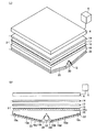
図1(a)及び(b)に、本発明の第1の態様の導光板を有する本発明の第2の態様の面状照明装置をバックライトユニットとして用いた本発明の第3の態様の液晶表示装置の概略斜視図及び概略断面図をそれぞれ示す。液晶表示装置10は、図1(a)及び(b)に示すように、基本的に、バックライトユニット2と、バックライトユニット2の光射出面側に配置される液晶表示パネル4と、それらを駆動するための駆動ユニット6とを有する。
FIGS. 1A and 1B show a third embodiment of the present invention in which the planar illumination device of the second embodiment of the present invention having the light guide plate of the first embodiment of the present invention is used as a backlight unit. The schematic perspective view and schematic sectional drawing of a liquid crystal display device are shown, respectively. As shown in FIGS. 1A and 1B, the liquid
バックライトユニット2は、液晶表示パネル4の背後から、液晶表示パネル4の全面に均一な光を照射するための面状照明装置であり、液晶表示パネル4の画像表示面と略同一の光射出面(発光面)を有する。バックライトユニット2は、図1に示すように、基本的には、光源12と、拡散シート14と、2枚のプリズムシート16及び17と、導光板18と、リフレクタ20と、反射シート22とを有する。
The
光源12は、細径の棒状の冷陰極管であり、液晶表示パネル4を照明するために用いられる。光源12は、導光板18に形成された平行溝18f内に配置され、駆動ユニット6と接続されている。ここでは、光源12として冷陰極管を用いたが、本発明はこれに限定されず、棒状光源であれば、どのようなものでもよい。光源12としては、例えば、通常の蛍光管や、LED(発光ダイオード)なども用いることもできる。
The
図1において、拡散シート14は、導光板18の光射出面18aから出射する光を拡散して均一化するためのものであり、例えば、PET(ポリエチレンテレフタレート)、PP(ポリプロピレン)、PC(ポリカーボネート)、PMMA(ポリメチルメタクリレート)、ベンジルメタクリレートやMS樹脂、その他のアクリル系樹脂、あるいはCOP(シクロオレフィンポリマー)のような光学的に透明な樹脂からなる平板状部材に光拡散性を付与して形成される。その方法は特に限定されないが、例えば、上記平板状部材の表面に微細凹凸加工や研磨による表面粗化(以降これらを施した面を「砂擦り面」という。)を施して拡散性を付与したり、表面に光を散乱させるシリカ、酸化チタン、酸化亜鉛等の顔料もしくは樹脂やガラス、ジルコニア等のビーズ類をバインダとともに塗工したり、上記の樹脂中に光を散乱させる前述の顔料、ビーズ類を混練することで形成される。本発明において、拡散シート14としては、マットタイプやコーティングタイプの拡散シートを用いることができる。
本発明において、拡散シート14としては、上記の素材を用い、かつ、光拡散性を付与した厚み500μm以下のフィルム状部材を用いることも好ましい。
In FIG. 1, a
In the present invention, as the
拡散シート14は、導光板18の光射出面18aから所定の距離だけ離して配置されることが好ましく、その距離は導光板18の光射出面18aからの光量分布に応じて適宜変更し得る。このように拡散シート14を導光板18の光射出面18aから所定の間隔だけ離すことにより、導光板18の光射出面18aから射出する光が、光射出面18aと拡散シート14の間で更にミキシング(混合)される。これにより、拡散シート14を透過して液晶表示パネル4を照明する光の照度を、より一層均一化することができる。拡散シート14を導光板18の光射出面18aから所定の間隔だけ離す方法としては、例えば、拡散シート14と導光板18との間にスペーサを設ける方法を用いることができる。
特に、バックライトユニット2の厚みを少し厚くしてもよい場合には、導光板18の平行溝18fの断面形状によって、平行溝18fに相当する導光板18の光射出面18aにおける照度のピーク値を十分に低減する必要はなく、部分的に低減するとともに拡散シート14と導光板18の光射出面18aとの間に間隙を設けて、拡散シート14から射出される照明光を照度分布を均一にしても良い。また、導光板18の平行溝18fの断面形状の改良(平行溝の先端部分の先細化)に限界があり、平行溝18fに相当する導光板18の光射出面18aにおける照度のピーク値を完全に低減できない場合や十分に低減できない場合にも、拡散シート14と導光板18の光射出面18aとの間に間隙を設けて、拡散シート14から射出される照明光の照度分布を均一にしても良い。
The
In particular, when the thickness of the
プリズムシート16及び17は、複数のプリズムを平行に配列させることにより形成された透明なシートであり、導光板18の光射出面18aから出射する光の集光性を高めて輝度を改善することができる。プリズムシート16及び17の一方は、そのプリズム列の延在する方向が導光板18の平行溝18fと平行になるように配置され、他方は垂直になるように配置されている。すなわち、プリズムシート16及び17は、プリズム列の延在する方向が互いに垂直になるように配置されている。また、プリズムシート16は、プリズムの頂角が導光板18の光射出面18aと対向するように配置される。ここで、プリズムシート16及び17の配置順序は、導光板の直上に、導光板の平行溝と平行な方向に延在するプリズムを有するプリズムシート16を配置し、そのプリズムシート16の上に、導光板18の平行溝18fと垂直な方向に延在するプリズムを有するプリズムシート17を配置しても良く、また、その逆でも良い。
The
また、図示例では、プリズムシートを用いたが、プリズムシートの代わりに、プリズムに類する光学素子が規則的に配置されたシートを用いても良い。また、レンズ効果を有する素子、例えば、レンチキュラーレンズ、凹レンズ、凸レンズ、ピラミッド型などの光学素子を規則的に備えるシートをプリズムシートの代わりに用いることもできる。 In the illustrated example, a prism sheet is used, but a sheet in which optical elements similar to prisms are regularly arranged may be used instead of the prism sheet. In addition, a sheet that regularly includes an optical element such as a lens effect, for example, a lenticular lens, a concave lens, a convex lens, or a pyramid type can be used instead of the prism sheet.
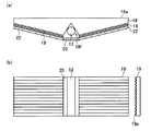
本発明においては、更に、図2(a)及び(b)に示すように、反射シート22と導光板18の光射出面18aと反対側の傾斜面18dとの間にもプリズムシート19を設けることが好ましい。図2(a)は、反射シート22と導光板18の傾斜面18dとの間にプリズムシート19が配置されている様子を示す概略断面図であり、図2(b)は、反射シート22と導光板18の傾斜面18dとの間に配置されているプリズムシート19を導光板側から見た概略平面図及び概略横断面図である。反射シート22と導光板18の傾斜面18dとの間に設けられるプリズムシート19は、プリズム19aの延在する方向が導光板18の平行溝18fと垂直になるように配置されるとともに、プリズム19aの頂角が導光板18の傾斜面18bと対向するように配置することが好ましい。
In the present invention, as shown in FIGS. 2A and 2B, a
ここではプリズムシートを用いたが、プリズムシートと同様の効果を有する光学素子を用いても良く、レンズ効果を有する光学素子、例えば、レンチキュラーレンズ、凹レンズ、凸レンズ、ピラミッド型などの光学素子が規則的に配置されたシートを設けても良い。
なお、図示例においては、プリズムシート16および17、さらに好ましくはプリズムシート19を用いているが、導光板18の平行溝18fによる光射出面18aにおける照度がより均一化されている場合には、プリズムシート19はもちろん不要であるし、プリズムシート16および17のどちらか一方、または両方を用いなくても良い。高価なプリズムシートの使用枚数を減らし、あるいは、プリズムシートの使用をやめることにより、装置コストを低減させることができる。
Although a prism sheet is used here, an optical element having the same effect as the prism sheet may be used, and an optical element having a lens effect, for example, an optical element such as a lenticular lens, a concave lens, a convex lens, or a pyramid type is regular. You may provide the sheet | seat arrange | positioned.
In the illustrated example, the
図1において、反射シート22は、導光板18の背面(図中、下面)から漏洩する光を反射して、再び導光板18に入射させるためのものであり、光の利用効率を向上させることができる。反射シート22は、導光板18の下面(傾斜面)を覆うように形成される。リフレクタ20は、導光板18の平行溝18fを塞ぐように光源12の背後に設けられる。リフレクタ20は、光源12の下面から光を反射して、導光板18の平行溝18fの側壁面から光を入射させることができる。
In FIG. 1, the
反射シート22は、導光板18の背面(図中、下面)から漏洩する光を反射することができるのであれば、どのような材料で形成されてもよく、例えば、PETやPP(ポリプロピレン)等にフィラーを混練後延伸することによりボイドを形成して反射率を高めた樹脂シート、透明もしくは上記のような白色の樹脂シート表面にアルミ蒸着などで鏡面を形成したシート、アルミ等の金属箔もしくは金属箔を担持した樹脂シート、あるいは表面に十分な反射性を有する金属薄板により形成することができる。また、リフレクタ20は、例えば、上記反射シートと同じ素材、すなわち、表面に十分な反射性を付与した樹脂素材、金属箔もしくは金属板により形成することができる。
The
図1において、導光板18は、矩形状の光射出面18aと、その一辺に平行な厚肉部18bと、この厚肉部18bの両側に前記一辺に平行に形成される薄肉端部18cと、厚肉部18bから前記一辺に直行する方向に両側の薄肉端部18cに向かって肉厚が薄くなり、傾斜面18dを形成する傾斜背面部18eと、肉厚部18bに前記一辺に平行に形成される、光源12を収納するための平行溝18fとを有する。すなわち、導光板18は、表面の外形形状が矩形状の平板であり、透明樹脂により形成されている。導光板18は、一方の面が平坦となっており、他方の面が、一方の辺に向かうにしたがって板厚が薄くなるように、一方の面に対して傾斜している。ここでは、傾斜面18dを平面として形成しているが、曲面としてもよい。
In FIG. 1, a
導光板18の厚肉部18bの光射出面18aと反対側には、光源12を収容するための平行溝18fが長手方向に延在して形成されている。平行溝18fの深さは、光源12の一部が導光板18の下面からはみ出さないように決定されることが好ましく、光源12の寸法や導光板18の機械的強度、経時変化を考慮して決定することが好ましい。また導光板18の肉厚部18bや薄肉端部18cの厚みは、光源12の寸法に応じて任意に変更することができる。ここで、導光板18の平行溝18fは、導光板18の長手方向に対して垂直な方向に形成してもよいが、平行溝18fに収容される光源12からの光利用効率を高めるためには長手方向に形成することが好ましい。
On the opposite side of the
図1に示す構造を有する導光板18において、その平行溝18fに配置された光源12から放射される光のうち、平行溝18fを形成する側壁から導光板18の内部に入射した光は、導光板18の傾斜面18dで反射した後、光射出面18aから出射する。このとき、導光板18の下面から一部の光が漏洩するが、その漏洩した光は、導光板18の傾斜面18b側に形成された反射シート18により反射して再び導光板18の内部に入射して光射出面18aから出射する。こうして、導光板18の光射出面18aから均一な光が放射される。
In the
導光板18は、例えば、加熱した原料樹脂を押し出し成形や射出成形によって成形する方法、型中でモノマー、オリゴマー等を重合させて成形する注型重合法等を用いて製造することができる。導光板18の材料としては、例えば、PET(ポリエチレンテレフタレート)、PP(ポリプロピレン)、PC(ポリカーボネート)、PMMA(ポリメチルメタクリレート)、ベンジルメタクリレートやMS樹脂、その他のアクリル系樹脂、あるいはCOP(シクロオレフィンポリマー)などの透明樹脂を用いることができる。透明樹脂には、光を散乱させるための微粒子を混入させても良く、これにより光射出面18aからの光の出射効率を一層高めることができる。
The
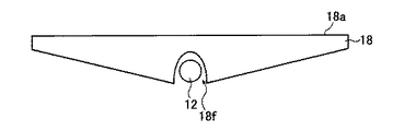
図1において、導光板18の平行溝18fは、当該平行溝18fの長さ方向に垂直な断面形状(以下、単に平行溝の断面形状という)が三角形状になるように形成されている。ここでは、平行溝18fの断面形状を三角形状としたが、本発明においては、平行溝18fの断面形状は、当該平行溝18fの最深部又は中心を通って導光板18fの、光射出面に垂直な中心線に対して対称であって、光出射面18aに向かって細くなるような形状であればよく、例えば、図3及び4に示すように、双曲線形状、楕円形状することができる。或いは、導光板18の平行溝18fの断面形状は懸垂線形状でも良い。
In FIG. 1, the
また、本発明においては、平行溝の断面形状において、平行溝の最深部(平行溝を形成する側壁の接続部)が尖点となるような形状にすることもできる。すなわち、平行溝の先端部分の断面形状が、互いに交わる先鋭な1つの交点を有する、平行溝の中心を通って導光板の光射出面に垂直な中心線に対して対称な2つの曲線又は直線の一部から形成することができる。本発明においては、導光板の平行溝の断面形状が、上記いずれの形状であっても、導光板の光射出面から均一な光を出射させることができる。 In the present invention, the cross-sectional shape of the parallel groove may be such that the deepest portion of the parallel groove (the connection portion of the side wall forming the parallel groove) is a cusp. That is, two curved lines or straight lines that are symmetrical with respect to a center line that passes through the center of the parallel groove and is perpendicular to the light exit surface of the light guide plate, the cross-sectional shape of the tip portion of the parallel groove having one sharp intersection that intersects each other It can form from a part of. In the present invention, even if the cross-sectional shape of the parallel groove of the light guide plate is any of the above shapes, uniform light can be emitted from the light exit surface of the light guide plate.
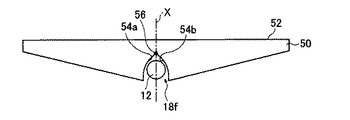
図5には、平行溝の先端部分の断面形状が、互いに交わる先鋭な1つの交点を有する、平行溝18fの中心を通って導光板の光射出面に垂直な中心線に対して対称な2つの曲線の一部からなる場合の一例を示した。図5に示した導光板50は、平行溝の中心を通って導光板50の光射出面52に垂直な中心線Xに対して対称な2つの曲線54a及び54bが円弧の場合である。この場合は、図5に示すように、平行溝18fを形成する一方の側壁に対応する円弧54aの中心の位置と他方の側壁に対応する円弧54bの中心の位置が異なるように形成される。これにより円弧状の両側壁が交わる部分56は、図5に示すように尖った形状となる。
In FIG. 5, the cross-sectional shape of the tip portion of the parallel groove is symmetrical 2 with respect to a center line perpendicular to the light exit surface of the light guide plate through the center of the
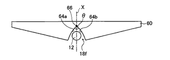
また、図6には、平行溝の先端部分の断面形状が、互いに交わる先鋭な1つの交点を有する、平行溝の中心を通って導光板の光射出面に垂直な中心線に対して対称な2つの曲線の一部からなる場合の更に別の例を示した。図6に示した導光板60は、平行溝18fの中心を通って導光板の光射出面に垂直な中心線Xに対して対称な2つの曲線64a及び64bが放物線の場合である。図6においては、平行溝18fの一方の側壁に対応する放物線64aの焦点と、他方の側壁22bに対応する放物線64bの焦点とが互いに異なるように、平行溝18fの側壁が形成される。
Further, in FIG. 6, the cross-sectional shape of the tip portion of the parallel groove is symmetrical with respect to a center line perpendicular to the light exit surface of the light guide plate through the center of the parallel groove having one sharp intersection that intersects each other. Still another example in the case of consisting of a part of two curves is shown. The
図6に示すように、平行溝の先端部分の断面形状が、交点66で交わる2つの曲線64a及び64bから形成される場合において、平行溝18fの一方の側壁に対応する曲線64aの、交点(尖点)66における接線と、他方の側壁に対応する曲線64bの、交点66における接線が互いになす角θは、90度以下が好ましく、60度以下がより一層好ましい。
As shown in FIG. 6, in the case where the cross-sectional shape of the tip portion of the parallel groove is formed by two
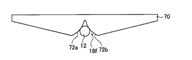
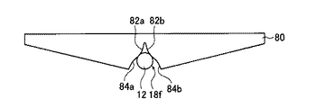
図3〜図6では、平行溝の断面形状において、平行溝の側壁を形成する曲線が、平行溝の中心に向かって凹状の導光板の例を示したが、これらとは異なる本発明の導光板の別の態様を図7及び図8に示す。図7は、平行溝18fの断面形状が、平行溝18fの中心に向かって凸の2つの曲線72a及び72bから形成される導光板70の例であり、図8は、平行溝18fの断面形状が、平行溝18fの中心に向かって凸の曲線82a及び82bと凹の曲線84a及び84bを組み合わせた曲線から形成される導光板80の例である。図7及び図8に示したような断面形状の平行溝を有する導光板70及び80も、輝線の発生を抑制しつつ光射出面から十分な照度の光を出射することができる。
FIGS. 3 to 6 show examples of the light guide plate in which the side walls of the parallel grooves are concave toward the center of the parallel grooves in the cross-sectional shape of the parallel grooves. Another embodiment of the light plate is shown in FIGS. FIG. 7 shows an example of the
このように、本発明においては、導光板の平行溝の断面形状において、平行溝に相当する部分は、平行溝の中心に向かって凸若しくは凹の曲線状又は直線状にすることができ、それらの組み合わせであってもよい。これらの曲線は、図示例の円弧に限定されず、平行溝の中心に向かって凸または凹の、楕円、放物線、または双曲線などの曲線の一部であればよい。また、本発明においては、平行溝の先端部分の断面形状が、後述するように先細化されていれば、平行溝を構成する曲線は、平行溝の中心に向かって凸または凹の、円、楕円、放物線、または双曲線などの曲線の一部であれば良く、10次の関数によって近似できる曲線であることが好ましい。 Thus, in the present invention, in the cross-sectional shape of the parallel groove of the light guide plate, the portion corresponding to the parallel groove can be formed in a convex or concave curved or linear shape toward the center of the parallel groove, A combination of these may be used. These curves are not limited to the arc in the illustrated example, and may be any part of a curve such as an ellipse, a parabola, or a hyperbola that is convex or concave toward the center of the parallel groove. In the present invention, if the cross-sectional shape of the tip portion of the parallel groove is tapered as will be described later, the curve constituting the parallel groove is a circle that is convex or concave toward the center of the parallel groove, It may be a part of a curve such as an ellipse, a parabola, or a hyperbola, and is preferably a curve that can be approximated by a tenth-order function.
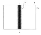
本発明の導光板においては、図9に示すように、ある中心線Xにおいて網点の密度が高くその中心線Xから両側(中心線に対して垂直方向)に向かうにしたがって次第に網点の密度が低くなるような網点パターン92を導光板18の光射出面18aに、例えば、印刷により形成してもよい。このような網点パターン92を、網点パターンの中心線Xが導光板18の平行溝の中心線に対応する位置と一致するように、導光板18の光射出面18aに形成することにより、導光板18の光射出面18aにおける輝線の発生やムラを抑制することができる。また、網点パターン92を導光板18に印刷する代わりに、網点パターンが形成された薄いシートを光射出面上に積層しても良い。網点の形状は、矩形、円形、楕円形などを任意の形状にすることができ、網点の密度は、輝線の強さや広がりに応じて適宜選択することができる。また、このような網点パターンを印刷により形成する代わりに、網点パターンに対応する部分を砂擦り面として荒らしてもよい。このような砂擦り面は、導光板の平行溝の最深部や側壁に形成してもよい。
In the light guide plate of the present invention, as shown in FIG. 9, the density of halftone dots is high at a certain center line X, and the density of halftone dots gradually increases from the center line X toward both sides (perpendicular to the center line). A
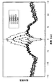
つぎに、導光板の平行溝の断面形状を種々の形状に変更したときに、導光板の光射出面から出射する光の照度分布について調べた。まず、本発明に従う導光板の例として、平行溝18fの断面形状が図1及び図3にそれぞれ示すような三角形及び双曲線の場合と、従来の導光板の例として断面形状が放物線、半円形(かまぼこ形)の場合について調べた。図10に、それらの導光板の光出射側の面における相対照度分布を示す。図10において、縦軸は相対照度を示し、横軸は、導光板の中心位置(平行溝の中心部分)からの距離を示す。ここで、相対照度は、次のようにして測定した。
本発明の導光板に光源を組み込み、導光板内に光を入射して光出射面より光が出射するようにした状態で、XYステージに固定し、導光板の出射面に垂直になるように照度計を固定する。そして照度計によって光出射面の位置における照度を測定して導光板の光出射面の特定位置に関する、照度の情報を得る。
その後、XYステージを移動させることにより、光出射面上の位置と照度の関係を求めて、その全面の平均値を算出する。各位置における照度をこの照度の平均値をそれぞれ割り返した比率が、その位置における相対照度となる。
なお、平行溝の軸方向に垂直な方向1軸を測定してその値を代表させることで、断面形状の比較等を簡便に行うこともできる。
なお、相対輝度を測定する場合には、照度計の代わりに輝度計を用いればよく、これにより、導光板の光出射側の面における相対輝度分布を得ることができる。
Next, the illuminance distribution of light emitted from the light exit surface of the light guide plate when the cross-sectional shape of the parallel grooves of the light guide plate was changed to various shapes was examined. First, as an example of the light guide plate according to the present invention, the cross-sectional shape of the
A light source is incorporated into the light guide plate of the present invention, light is incident on the light guide plate and light is emitted from the light exit surface, and is fixed to the XY stage so as to be perpendicular to the exit surface of the light guide plate. Fix the illuminometer. Then, the illuminance at the position of the light exit surface is measured by an illuminance meter to obtain illuminance information regarding the specific position of the light exit surface of the light guide plate.
Thereafter, the relationship between the position on the light exit surface and the illuminance is obtained by moving the XY stage, and the average value of the entire surface is calculated. The ratio obtained by dividing the illuminance at each position by the average value of the illuminance is the relative illuminance at that position.
In addition, cross-sectional shape comparison etc. can also be performed simply by measuring one axis | shaft perpendicular | vertical to the axial direction of a parallel groove, and making that value represent.
In the case of measuring the relative luminance, a luminance meter may be used instead of the illuminance meter, whereby the relative luminance distribution on the light emitting side surface of the light guide plate can be obtained.
図10からわかるように、導光板の平行溝の断面形状を双曲線にした場合に、平行溝に対応する部分における相対照度のピーク値が、傾斜背面部からの出射光によって形成される相対照度の平均値の10倍以下となっており、光射出面からの照度が略均一になっていることがわかる。一方、平行溝の断面形状が半円形又は放物線形の従来の導光板においては、図10に示すように、平行溝の中心部分、すなわち、光源の直上の位置において相対照度が高くなっており、輝線が発生していることがわかる。すなわち、従来の平行溝の断面形状が半円形状又は放物線形状の導光板においては、光射出面における照度が均一ではない。 As can be seen from FIG. 10, when the cross-sectional shape of the parallel groove of the light guide plate is a hyperbola, the peak value of the relative illuminance at the portion corresponding to the parallel groove is the relative illuminance formed by the light emitted from the inclined back surface. It is 10 times or less of the average value, and it can be seen that the illuminance from the light exit surface is substantially uniform. On the other hand, in the conventional light guide plate in which the cross-sectional shape of the parallel groove is semicircular or parabolic, the relative illuminance is high at the central portion of the parallel groove, that is, the position directly above the light source, as shown in FIG. It can be seen that bright lines are generated. That is, in a conventional light guide plate having a semicircular or parabolic cross-sectional shape, the illuminance on the light exit surface is not uniform.
また、平行溝の断面形状が三角形状の導光板においては、中心部分の相対照度は低くなっている。このような平行溝の断面形状が三角形状の場合は、以下に示すように、頂点を所定の幅で平坦にするか、比較的曲率半径の小さな曲面にすることによって、光射出面における照度を均一化することができる。 Further, in the light guide plate in which the cross-sectional shape of the parallel grooves is triangular, the relative illuminance at the center portion is low. When the cross-sectional shape of such parallel grooves is triangular, the illuminance on the light exit surface can be reduced by flattening the apex with a predetermined width or a curved surface with a relatively small radius of curvature, as shown below. It can be made uniform.
図11に、導光板の平行溝の断面形状が三角形状の場合において、平行溝の最深部(三角形状の平行溝の頂点部分)を平坦化し、その平坦部分の長さを種々の値に変化させたときに導光板の光射出面から出射する光の照度分布を示す。図11において、縦軸は相対照度を示し、横軸は、導光板に形成された平行溝の中心部からの距離を示す。ここでは、計算を簡単化するために、冷陰極管の直径を3mmとし、平坦部分の長さを1.5mm、1.0mm、0.5mm、0.25mmとした。図12(a)〜(d)に、平行溝の断面形状が三角形の場合に、平行溝の最深部の平坦部分の長さが1.5mm、1.0mm、0.5mm、0.25mmの導光板の概略断面図をそれぞれ示した。 In FIG. 11, when the cross-sectional shape of the parallel groove of the light guide plate is triangular, the deepest part of the parallel groove (the apex part of the triangular parallel groove) is flattened, and the length of the flat part is changed to various values. The illumination intensity distribution of the light radiate | emitted from the light-projection surface of a light-guide plate when it is made to show is shown. In FIG. 11, the vertical axis represents relative illuminance, and the horizontal axis represents the distance from the central portion of the parallel groove formed in the light guide plate. Here, in order to simplify the calculation, the diameter of the cold cathode tube was set to 3 mm, and the length of the flat portion was set to 1.5 mm, 1.0 mm, 0.5 mm, and 0.25 mm. 12A to 12D, when the cross-sectional shape of the parallel groove is a triangle, the length of the flat part at the deepest part of the parallel groove is 1.5 mm, 1.0 mm, 0.5 mm, and 0.25 mm. A schematic sectional view of the light guide plate is shown.
図11のグラフに示すように、平坦部分の長さに応じて、導光板の平行溝に対応する部分における相対照度が変化することがわかる。ここで、本発明においては、平行溝の最深部の平端部分を長くすることで照度を高めることができるが、長すぎると輝線となる恐れがあるため、平端部分の長さは、冷陰極管の直径の20%以下とすることが好ましく、10%以下とすることがより好ましい。 As shown in the graph of FIG. 11, it can be seen that the relative illuminance at the portion corresponding to the parallel groove of the light guide plate changes according to the length of the flat portion. Here, in the present invention, it is possible to increase the illuminance by lengthening the flat end portion of the deepest part of the parallel groove, but if it is too long, there is a possibility that a bright line is formed. The diameter is preferably 20% or less, more preferably 10% or less.
図13には、導光板の平行溝の断面形状が三角形状の導光板において、平行溝の最深部の形状を曲率半径Rの曲面形状にし、その曲面の曲率半径を種々の値に変化させたときに導光板の光射出面から出射する光の照度分布を示した。ここでは、冷陰極管の半径を3mmとし、頂点部分の曲率半径が0.25mm、0.5mm、1.0mm、1.5mmの導光板について測定した。図14(a)〜(d)に、平行溝の断面形状が三角形の場合に、頂点部分の曲率半径が0.25mm、0.5mm、1.0mm、1.5mmの導光板の概略断面図をそれぞれ示した。図13のグラフから、平行溝の頂点部分の曲率半径に応じて、導光板の平行溝に対応する部分における相対照度が変化し、頂点部分の曲率半径Rが0.25mmにおいて導光板の光射出面における相対照度が略均一化されているのがわかる。 In FIG. 13, in the light guide plate having a triangular cross section of the parallel groove of the light guide plate, the shape of the deepest part of the parallel groove is a curved shape with a curvature radius R, and the curvature radius of the curved surface is changed to various values. Sometimes the illuminance distribution of the light emitted from the light exit surface of the light guide plate is shown. Here, the radius of the cold-cathode tube was set to 3 mm, and the light guide plate having a radius of curvature of the apex portion of 0.25 mm, 0.5 mm, 1.0 mm, and 1.5 mm was measured. 14A to 14D, when the cross-sectional shape of the parallel groove is a triangle, schematic cross-sectional views of a light guide plate having a radius of curvature of the apex portion of 0.25 mm, 0.5 mm, 1.0 mm, and 1.5 mm. Respectively. From the graph of FIG. 13, the relative illuminance at the portion corresponding to the parallel groove of the light guide plate changes according to the radius of curvature of the vertex portion of the parallel groove, and the light emission of the light guide plate when the radius of curvature R of the vertex portion is 0.25 mm. It can be seen that the relative illuminance on the surface is substantially uniform.
以上から、導光板の平行溝の先端部分の形状が光射出面からの照度に大きく依存することがわかる。すなわち、導光板の平行溝の形状を本発明で示した形状になるように設計するだけで、導光板の光射出面における照度を最適に調整して均一化することができることがわかる。
導光板の表面において、照度と輝度は略同様に扱うことができる。それゆえ、図11及び13の相対照度のグラフから、本発明においては、輝度においても同様の傾向があると推測される。したがって、導光板の平行溝の形状を本発明で示した形状になるように設計することで、導光板の光射出面における輝度についても均一化できると考えられる。
なお、平行溝の先端部分の頂部(最深部)の断面形状が、平行溝の中心線に対して対称に先鋭な1つの交点が、面取りされた平坦状、もしくは、丸められた円形状のみならず、楕円形状、放物線状、または双曲線状であっても良いのはもちろんである。さらに、これに加え、上述したように、平行溝の先端部分の頂部(最深部)を砂擦り面とすることにより、照度又は輝度のピーク値を低減するようにしても良い。
From the above, it can be seen that the shape of the tip portion of the parallel groove of the light guide plate greatly depends on the illuminance from the light exit surface. That is, it can be seen that the illuminance on the light exit surface of the light guide plate can be optimally adjusted and made uniform simply by designing the shape of the parallel grooves of the light guide plate to the shape shown in the present invention.
On the surface of the light guide plate, illuminance and luminance can be handled in substantially the same manner. Therefore, from the graphs of relative illuminance in FIGS. 11 and 13, it is presumed that the same tendency exists in luminance in the present invention. Therefore, it is considered that the luminance on the light exit surface of the light guide plate can be made uniform by designing the shape of the parallel grooves of the light guide plate to be the shape shown in the present invention.
If the cross-sectional shape of the top (deepest part) of the tip of the parallel groove is only one chamfered flat shape or rounded circular shape with one sharp intersection symmetrically with respect to the center line of the parallel groove Of course, it may be oval, parabolic, or hyperbolic. Further, in addition to this, as described above, the peak value of illuminance or luminance may be reduced by using a top portion (deepest portion) of the tip portion of the parallel groove as a rubbing surface.
以上から、本発明の導光板の第1の形態においては、導光板18の光射出面18aにおける平行溝18f以外、すなわち傾斜背面18dに相当する部分(第2部分)に形成される照度の平均値に対する、導光板18の光射出面18aにおける平行溝18fに相当する部分(第1部分)に形成される輝線のピーク値(照度のピーク値)の比に応じて、導光板18の平行溝18fの先端形状の先細化を行う、すなわち、この比の値に応じて、導光板18の平行溝18fの先端形状の先細化の程度を制御する。なお、この場合においては、後述する第2の形態の場合のように、この比は、3以下、より好ましくは、2以下とするのが好ましい。
As mentioned above, in the 1st form of the light-guide plate of this invention, the average of the illumination intensity formed in the part (2nd part) equivalent to the
なお、この比は、バックライトユニット2の厚み(導光板18の光射出面18aと拡散シート14との間の距離)や、バックライトユニット2において使用される拡散シート14の拡散効率や枚数、プリズムシート16、17および19の拡散効率や使用枚数等に応じて、設定するのが好ましい。すなわち、バックライトユニット2の厚み(導光板18の光射出面18aと拡散シート14との間の距離)がある程度厚く(または大きく)できる場合や、バックライトユニット2において使用される拡散シート14の拡散効率が高く、使用枚数を多くできる場合や、プリズムシート16、17および19の拡散効率が高く、使用枚数を多くできる場合には、導光板18の光射出面18aから射出された照明光の拡散(ミキシングなど)を十分に行うことができるので、高コストとはなるが、導光板18の光射出面18aの第2部分の照度の平均値に対する、導光板18の光射出面18aの第1部分の照度のピーク値の比を、ある程度大きく設定することができる。しかし、そうでない場合には、低コスト化できるが、この比の値を小さく設定する必要がある。
This ratio is the thickness of the backlight unit 2 (the distance between the
一方、本発明の導光板の第2の形態においては、導光板18の光射出面18aの第1部分の照度のピーク値が、導光板18の光射出面18aの第2部分の照度の平均値の3倍以下、より好ましくは、2倍以下となるように、導光板18の平行溝18fの先端形状の先細化を行う。ここで、導光板18の光射出面18aの第1部分の照度のピーク値が、導光板18の光射出面18aの第2部分の照度の平均値の3倍以下となるようにするのは、導光板18の光射出面18aから射出された照明光の照度分布が、従来より均一化されるからであり、その結果、導光板18の光射出面18aから射出された照明光の拡散(ミキシングなど)をそれほど十分に行う必要がなく、拡散効率のあまり高くない低コストの拡散シート14の使用が可能となり、また使用枚数を減らすことができ、また、高価なプリズムシート16、17および19自体の使用を止めることができ、あるいは、拡散効率のあまり高くない低コストのプリズムシート16、17および19の使用が可能となったり、使用枚数を減らすことができるからである。
On the other hand, in the second embodiment of the light guide plate of the present invention, the peak value of the illuminance of the first portion of the
なお、本発明の第1の態様の導光板では、導光板18の平行溝18fの断面形状において、平行溝18fの先細化を行う先端部分は、棒状光源12の中心から光射出面18aに向かう垂線(X)に対する角度が、両側で90度以内となる部分、より好ましくは、60度以内となる部分とするのが好ましい。すなわち、本発明において、導光板18の光射出面18aの平行溝18fに相当する第1部分の照度のピーク値を低減するために、平行溝18fの先細化を行う部分は、平行溝18fの全体でも良いが、ピーク値の低減化が可能であれば、所定の先端部分で良い。
In the light guide plate according to the first aspect of the present invention, in the cross-sectional shape of the
以上、本発明の導光板及びそれを備えるバックライトユニット並びに液晶表示装置について詳細に説明したが、本発明は上記実施態様に限定はされず、本発明の主旨を逸脱しない範囲において、各種の改良や変更をしてもよいのはもちろんである。 As described above, the light guide plate, the backlight unit including the light guide plate, and the liquid crystal display device according to the present invention have been described in detail. However, the present invention is not limited to the above embodiments, and various improvements can be made without departing from the gist of the present invention. Of course, you may make changes.
例えば、本発明においては、図15に示すように、導光板18の光射出面18aが全て同一平面を形成するように導光板18を複数並列して配置して大型の導光板を構成することもできる。このように導光板18を並列して配置したときには、一方の導光板18の傾斜面18dと、それと接続する他方の導光板18’の傾斜面18d’とが交差しないように、すなわち、それら傾斜面の連結部分において滑らかな平面または曲面が形成されるように、導光板18の傾斜面18dの傾斜角度を調整することができる。図15に示した導光板においては、導光板18及び18’のそれぞれの傾斜面18d及び18d’によって形成される面がアーチ型になるように形成されている。
このような大サイズの光射出面を持つ導光板を用いることにより、大サイズの光照射面を持つバックライトユニットとすることができるので、大サイズの表示画面を持つ液晶表示装置に適用することができ、特に、壁掛けテレビなどの壁掛けタイプの液晶表示装置に適用することができる。
For example, in the present invention, as shown in FIG. 15, a large-sized light guide plate is configured by arranging a plurality of
By using such a light guide plate having a large light emitting surface, a backlight unit having a large light emitting surface can be obtained, and therefore, it can be applied to a liquid crystal display device having a large display screen. In particular, the present invention can be applied to a wall-mounted liquid crystal display device such as a wall-mounted television.
上述のように本発明による導光板を一つのユニットとして連結して大型の導光板を形成するには、別々に成形した本発明の導光板を薄肉部が接するように配置して、もしくは接合して形成してもよく、出射光の均一性を高める上では2個以上の本発明の導光板を連結した形状で一体に成形することが好ましい。
製造効率の観点からは、必要な画面サイズに相当する導光板を形成するのに必要な数の本発明の導光板ユニットを一体で成形することが好ましい。
As described above, in order to form a large light guide plate by connecting the light guide plates according to the present invention as a single unit, the light guide plates of the present invention that are separately formed are arranged or joined so that the thin-walled portions are in contact with each other. In order to improve the uniformity of the emitted light, it is preferable that the two or more light guide plates of the present invention are integrally formed in a connected shape.
From the viewpoint of manufacturing efficiency, it is preferable to integrally form the number of light guide plate units of the present invention necessary for forming a light guide plate corresponding to a required screen size.
また、本発明の導光板において、側面の面積などを考慮して、図16(a)に示すように、導光板18の側面に反射板24を配置してもよい。導光板18を複数配置する場合には、図16(b)に示すように、最も外側に配置される導光板18の側面に反射板24を配置すればよい。このような反射板24を側面に配置することで導光板18の側面からの光の漏出を防止することができ、光利用効率を一層高めることができる。反射板24は、前述した反射シートやリフレクタと同様な材料を用いて形成することができる。
In the light guide plate of the present invention, the reflecting
2 バックライトユニット
4 液晶表示パネル
6 駆動ユニット
10 液晶表示装置
12 光源
14 拡散シート
16、17、19 プリズムシート
18、50、60、70、80、100 導光板
18a、52 光射出面
18b 厚肉部
18c 薄肉端部
18d 傾斜面
18e 傾斜背面部
18f 平行溝
20 リフレクタ
22 反射シート
24 反射板
54a、54b 円弧曲線
56 交点
64a、64b 放物線
72a、72b、82a、82b、84a、84b 曲線
92 網点パターン
2 Backlight unit 4 Liquid crystal display panel 6
Claims (17)
その一辺に平行で矩形状略中央部に位置する厚肉部と、
前記厚肉部に平行に形成される薄肉端部と、
棒状光源を収納するための平行溝が、前記厚肉部の略中央に前記一辺と平行に形成されており、
前記平行溝の両側に前記棒状光源の軸を含み矩形状光出射面に対して垂直な面に対して対称であり、
前記厚肉部から前記一辺に直交する方向に両側の前記薄肉端部に向かって肉厚が薄くなり、
傾斜背面を形成する傾斜背面部と、を有する透明な導光板であって、
前記矩形状光射出面の前記平行溝に相当する第1部分において前記平行溝に収納された棒状光源からの射出光によって形成される照度又は輝度のピーク値が、前記傾斜背面部に相当する第2部分において前記射出光によって形成される照度又は輝度の平均値の3倍以下となるように、前記平行溝の前記直交方向の断面形状において、前記平行溝の前記矩形状光射出面に垂直な中心線に対して、前記矩形状光射出面に向かって前記平行溝の先端部分を対称に細くしており、
前記平行溝の少なくとも前記先端部分の断面形状が、互いに交わる先鋭な1つの交点を持つ、前記中心線に対して対称な2つの曲線の一部からなるか、または前記平行溝の中心に向かって凸または凹の、円、楕円、放物線または双曲線の一部からなることを特徴とする導光板。 A rectangular light exit surface;
A thick wall portion that is parallel to the one side and located in a substantially rectangular central portion;
A thin end formed in parallel to the thick portion;
A parallel groove for storing the rod-shaped light source is formed in parallel with the one side at the approximate center of the thick part,
The axis of the rod-shaped light source is included on both sides of the parallel groove and is symmetric with respect to a plane perpendicular to the rectangular light exit surface,
The thickness decreases from the thick part toward the thin end on both sides in the direction perpendicular to the one side,
A transparent light guide plate having an inclined back surface forming an inclined back surface,
The peak value of illuminance or luminance formed by the light emitted from the rod-shaped light source housed in the parallel groove in the first portion corresponding to the parallel groove on the rectangular light exit surface corresponds to the inclined back surface portion. In the cross-sectional shape of the parallel groove in the orthogonal direction so as to be equal to or less than three times the average value of the illuminance or luminance formed by the emitted light in two portions, it is perpendicular to the rectangular light emitting surface of the parallel groove. The tip of the parallel groove is thinned symmetrically toward the rectangular light exit surface with respect to the center line,
The cross-sectional shape of at least the tip portion of the parallel groove is formed of a part of two curves symmetrical with respect to the center line and having one sharp intersection intersecting each other, or toward the center of the parallel groove A light guide plate comprising a convex or concave part of a circle, ellipse, parabola or hyperbola.
前記導光板の前記平行溝に収納される棒状光源と、
前記平行溝を塞ぐように前記棒状光源を背後に設けられるリフレクタと、
前記導光板の前記厚肉部の両側の前記傾斜背面部の前記傾斜背面に取り付けられる反射シートと、
前記導光板の前記矩形状光出射面上に配置される拡散シートとを有することを特徴とする面状照明装置。 The light guide plate according to any one of claims 1 to 13 ,
A rod-shaped light source housed in the parallel groove of the light guide plate;
A reflector provided behind the bar light source so as to close the parallel grooves;
A reflective sheet attached to the inclined back surface of the inclined back surface on both sides of the thick portion of the light guide plate;
A planar illumination device comprising: a diffusion sheet disposed on the rectangular light exit surface of the light guide plate.
このバックライトユニットの光出射面側に配置される液晶表示パネルと、前記バックライトユニットおよび前記液晶表示パネルを駆動する駆動ユニットとを有することを特徴とする液晶表示装置。 A backlight unit comprising the planar illumination device according to any one of claims 14 to 16 ,
A liquid crystal display device comprising: a liquid crystal display panel disposed on a light emission surface side of the backlight unit; and the drive unit for driving the backlight unit and the liquid crystal display panel.
Priority Applications (6)
| Application Number | Priority Date | Filing Date | Title |
|---|---|---|---|
| JP2004045463A JP4264013B2 (en) | 2004-02-20 | 2004-02-20 | Light guide plate, planar illumination device using the same, and liquid crystal display device |
| US10/588,935 US8210731B2 (en) | 2004-02-20 | 2005-02-18 | Light guide plate, and planar lighting device and liquid crystal display device using the same |
| EP05710687A EP1716438A2 (en) | 2004-02-20 | 2005-02-18 | Light guide plate, and planar lighting device and liquid crystal display device using the same |
| CNA2005800053385A CN1922515A (en) | 2004-02-20 | 2005-02-18 | Light guide plate, and planar lighting device and liquid crystal display device using the same |
| TW094104747A TW200537204A (en) | 2004-02-20 | 2005-02-18 | Light guide plate, and planar lighting device and liquid crystal display device using the same |
| PCT/JP2005/003087 WO2005080863A2 (en) | 2004-02-20 | 2005-02-18 | Light guide plate, and planar lighting device and liquid crystal display device using the same |
Applications Claiming Priority (1)
| Application Number | Priority Date | Filing Date | Title |
|---|---|---|---|
| JP2004045463A JP4264013B2 (en) | 2004-02-20 | 2004-02-20 | Light guide plate, planar illumination device using the same, and liquid crystal display device |
Publications (3)
| Publication Number | Publication Date |
|---|---|
| JP2005234397A JP2005234397A (en) | 2005-09-02 |
| JP2005234397A5 JP2005234397A5 (en) | 2006-06-29 |
| JP4264013B2 true JP4264013B2 (en) | 2009-05-13 |
Family
ID=34879390
Family Applications (1)
| Application Number | Title | Priority Date | Filing Date |
|---|---|---|---|
| JP2004045463A Expired - Lifetime JP4264013B2 (en) | 2004-02-20 | 2004-02-20 | Light guide plate, planar illumination device using the same, and liquid crystal display device |
Country Status (6)
| Country | Link |
|---|---|
| US (1) | US8210731B2 (en) |
| EP (1) | EP1716438A2 (en) |
| JP (1) | JP4264013B2 (en) |
| CN (1) | CN1922515A (en) |
| TW (1) | TW200537204A (en) |
| WO (1) | WO2005080863A2 (en) |
Families Citing this family (35)
| Publication number | Priority date | Publication date | Assignee | Title |
|---|---|---|---|---|
| US7868970B2 (en) | 2004-11-09 | 2011-01-11 | Fujifilm Corporation | Light guide plate, as well as a planar lighting device and liquid crystal display apparatus using the same |
| WO2006085526A1 (en) * | 2005-02-08 | 2006-08-17 | Fujifilm Corporation | Light guide plate, and planar lighting device and liquid crystal display device using such light guide plate |
| WO2006104203A1 (en) * | 2005-03-29 | 2006-10-05 | Fujifilm Corporation | Light conducting member, planar illuminator employing it, and rod-like illuminator |
| JP2006339320A (en) * | 2005-05-31 | 2006-12-14 | Omron Corp | Luminescence optical source and outgoing method of light therein |
| EP1734388A1 (en) * | 2005-06-14 | 2006-12-20 | Ricoh Company, Ltd. | Optical irradiation apparatus, image reading apparatus using the same, and image forming apparatus using the same |
| US20080212315A1 (en) * | 2005-09-19 | 2008-09-04 | Koninklijke Philips Electronics, N.V. | Illumination System for Illumination Display Devices, and Display Device Provided with Such an Illumination System |
| JP2007155791A (en) | 2005-11-30 | 2007-06-21 | Fujifilm Corp | Surface light source device |
| US7445358B2 (en) | 2005-12-27 | 2008-11-04 | Fujifilm Corporation | Light guide plate and a planar lighting device using the same |
| JP4629585B2 (en) * | 2006-01-17 | 2011-02-09 | 富士フイルム株式会社 | Light guide plate and planar illumination device using the same |
| JP4648209B2 (en) * | 2006-02-02 | 2011-03-09 | 富士フイルム株式会社 | Surface lighting device |
| JP4524255B2 (en) | 2006-02-07 | 2010-08-11 | 富士フイルム株式会社 | Surface lighting device |
| JP4652987B2 (en) * | 2006-02-09 | 2011-03-16 | 富士フイルム株式会社 | Surface lighting device |
| CN100543549C (en) * | 2006-03-22 | 2009-09-23 | 鸿富锦精密工业(深圳)有限公司 | Back light system |
| JP4699936B2 (en) * | 2006-04-28 | 2011-06-15 | 富士フイルム株式会社 | Planar illumination device and liquid crystal display device using the same |
| JP4155310B2 (en) * | 2006-06-02 | 2008-09-24 | ソニー株式会社 | Backlight device, liquid crystal display device, and electronic apparatus using liquid crystal display device |
| WO2008040306A1 (en) * | 2006-09-29 | 2008-04-10 | Osram Opto Semiconductors Gmbh | Optical waveguide and optical apparatus |
| US7746517B2 (en) * | 2007-01-25 | 2010-06-29 | Lexmark International, Inc. | Image illumination and capture in a scanning device |
| JP5153152B2 (en) | 2007-01-31 | 2013-02-27 | 富士フイルム株式会社 | Surface lighting device |
| JP5414224B2 (en) | 2007-10-19 | 2014-02-12 | 富士フイルム株式会社 | Surface lighting device |
| JP2010080401A (en) | 2008-09-29 | 2010-04-08 | Fujifilm Corp | Planar lighting system |
| EP2480919A1 (en) * | 2009-09-23 | 2012-08-01 | Koninklijke Philips Electronics N.V. | Light guide, illumination system, backlighting system and display device |
| CN101980059B (en) * | 2010-08-30 | 2012-12-19 | 应骏 | Light transmission panel and display image correcting method thereof |
| CN102156320B (en) * | 2011-02-25 | 2013-06-26 | 深圳市华星光电技术有限公司 | Side-entrance type light guide plate assembly and backlight module |
| KR101859413B1 (en) * | 2011-12-26 | 2018-05-21 | 삼성디스플레이 주식회사 | A display module and an apparatus having the same |
| US9052544B2 (en) * | 2012-03-26 | 2015-06-09 | Shenzhen China Star Optoelectronics Technology Co., Ltd | Direct-light backlight module and liquid crystal display device |
| KR102232058B1 (en) * | 2012-09-19 | 2021-03-24 | 엘지디스플레이 주식회사 | backlight unit and liquid crystal display module including the same |
| TWI490607B (en) * | 2012-10-15 | 2015-07-01 | 群康科技(深圳)有限公司 | Display apparatus and light emitting module and light-guiding plate thereof |
| TWI485483B (en) * | 2012-10-16 | 2015-05-21 | Innocom Tech Shenzhen Co Ltd | Light-guiding plate, light emitting module and display apparatus |
| US9784902B2 (en) * | 2013-03-25 | 2017-10-10 | 3M Innovative Properties Company | Dual-sided film with split light spreading structures |
| EP3362736A4 (en) * | 2015-10-13 | 2019-03-13 | Ameritech LLC | Luminaire including light emitting diodes |
| US10739513B2 (en) | 2018-08-31 | 2020-08-11 | RAB Lighting Inc. | Apparatuses and methods for efficiently directing light toward and away from a mounting surface |
| US10801679B2 (en) | 2018-10-08 | 2020-10-13 | RAB Lighting Inc. | Apparatuses and methods for assembling luminaires |
| JP7382563B2 (en) * | 2019-05-23 | 2023-11-17 | パナソニックIpマネジメント株式会社 | lighting equipment |
| JP7204304B2 (en) * | 2019-07-31 | 2023-01-16 | 矢崎総業株式会社 | pointer light emitting device |
| US11594665B2 (en) * | 2019-08-02 | 2023-02-28 | Nichia Corporation | Light-emitting unit and surface-emission light source |
Family Cites Families (13)
| Publication number | Priority date | Publication date | Assignee | Title |
|---|---|---|---|---|
| US5034864A (en) * | 1989-04-25 | 1991-07-23 | Mitsubishi Rayon Co., Ltd. | Planar light-source device and illumination apparatus using the same |
| JPH05249320A (en) * | 1992-03-04 | 1993-09-28 | Nisshin Hightech Kk | Optical waveguide device for surface illumination |
| JPH071428U (en) * | 1993-06-04 | 1995-01-10 | 株式会社エンプラス | Surface light source |
| JPH08271886A (en) | 1995-03-29 | 1996-10-18 | Toshiba Corp | Surface light source device and display device using the same |
| JPH0862426A (en) * | 1994-08-16 | 1996-03-08 | Nec Corp | Back light of liquid crystal display |
| JP3603462B2 (en) * | 1996-03-28 | 2004-12-22 | セイコーエプソン株式会社 | Backlight driving device and driving method |
| JP3319945B2 (en) * | 1996-05-13 | 2002-09-03 | 株式会社エンプラス | Surface light source device |
| JP3427636B2 (en) * | 1996-09-06 | 2003-07-22 | オムロン株式会社 | Surface light source device and liquid crystal display device |
| JP3841893B2 (en) * | 1996-11-05 | 2006-11-08 | 三菱電機株式会社 | Backlight unit and liquid crystal display device using the same |
| JPH11149073A (en) * | 1997-11-18 | 1999-06-02 | Matsushita Electric Ind Co Ltd | Surface light source device and liquid crystal display device |
| US6865325B2 (en) * | 2001-04-19 | 2005-03-08 | International Business Machines Corporation | Discrete pattern, apparatus, method, and program storage device for generating and implementing the discrete pattern |
| US6923554B2 (en) * | 2003-02-17 | 2005-08-02 | Heng Sheng Kuo | Backlight module |
| JP2004302067A (en) * | 2003-03-31 | 2004-10-28 | Toyota Industries Corp | Light guide plate, lighting device, and liquid crystal display device |
-
2004
- 2004-02-20 JP JP2004045463A patent/JP4264013B2/en not_active Expired - Lifetime
-
2005
- 2005-02-18 US US10/588,935 patent/US8210731B2/en active Active
- 2005-02-18 CN CNA2005800053385A patent/CN1922515A/en active Pending
- 2005-02-18 TW TW094104747A patent/TW200537204A/en unknown
- 2005-02-18 WO PCT/JP2005/003087 patent/WO2005080863A2/en not_active Application Discontinuation
- 2005-02-18 EP EP05710687A patent/EP1716438A2/en not_active Withdrawn
Also Published As
| Publication number | Publication date |
|---|---|
| WO2005080863A3 (en) | 2006-02-02 |
| TW200537204A (en) | 2005-11-16 |
| WO2005080863A2 (en) | 2005-09-01 |
| US20070165422A1 (en) | 2007-07-19 |
| EP1716438A2 (en) | 2006-11-02 |
| US8210731B2 (en) | 2012-07-03 |
| CN1922515A (en) | 2007-02-28 |
| JP2005234397A (en) | 2005-09-02 |
Similar Documents
| Publication | Publication Date | Title |
|---|---|---|
| JP4264013B2 (en) | Light guide plate, planar illumination device using the same, and liquid crystal display device | |
| JP4855944B2 (en) | Connecting light guide plate, planar illumination device using the same, and liquid crystal display device | |
| JP4607648B2 (en) | Light guide plate, planar illumination device including the same, and liquid crystal display device | |
| US7556391B2 (en) | Transmittance adjuster unit, a planar illumination device, a liquid crystal display device using the same, and a method of arranging transmittance adjusters | |
| KR100399085B1 (en) | Surface light source device of side light type | |
| JP4436105B2 (en) | Reflector, illumination device, light guide plate, and display device | |
| JP4814221B2 (en) | Light guide member, planar illumination device using the same, and bar illumination device | |
| WO2006004160A1 (en) | Light guide member, planar lighting apparatus using the light guide member, and bar-like lighting apparatus | |
| JP2009135116A (en) | Planar light source device, prism sheet, display, and information processor | |
| JP4542478B2 (en) | Light guide plate, planar illumination device using the same, and liquid crystal display device | |
| JP4555249B2 (en) | Transmittance adjuster unit, planar illumination device using the same, and liquid crystal display device | |
| JP2006301518A (en) | Light guide plate, surface lighting device using the same and liquid crystal display device | |
| JP2005085671A (en) | Light guide plate and plane light source device | |
| JP4750679B2 (en) | Surface illumination device and liquid crystal display device | |
| JP4546360B2 (en) | Transmittance adjuster unit, planar illumination device using the same, and liquid crystal display device | |
| JP4963726B2 (en) | Surface illumination device and liquid crystal display device | |
| JP2007027044A (en) | Light guide plate, planar lighting device equipped with it, and liquid crystal display equipped with it | |
| JP2012204323A (en) | Planar lighting system | |
| WO2005121639A1 (en) | Optical waveguide, and planar illuminating apparatus and liquid crystal display apparatus using the optical waveguide | |
| WO2005121638A1 (en) | Light guide plate, planar lighting apparatus using the light guide plate, and liquid crystal display | |
| JP2006318754A (en) | Transmissivity adjuster unit, planar illumination device, and liquid crystal display device using planer illumination device | |
| JP2006339043A (en) | Planar lighting device, and liquid crystal display device with same | |
| WO2005114046A1 (en) | Optical waveguide, planar illuminating device using the same and liquid crystal display device | |
| JP2004319399A (en) | Light guide block and flat lighting system |
Legal Events
| Date | Code | Title | Description |
|---|---|---|---|
| A521 | Written amendment |
Free format text: JAPANESE INTERMEDIATE CODE: A523 Effective date: 20060512 |
|
| A621 | Written request for application examination |
Free format text: JAPANESE INTERMEDIATE CODE: A621 Effective date: 20060512 |
|
| A711 | Notification of change in applicant |
Free format text: JAPANESE INTERMEDIATE CODE: A712 Effective date: 20061206 |
|
| RD04 | Notification of resignation of power of attorney |
Free format text: JAPANESE INTERMEDIATE CODE: A7424 Effective date: 20080711 |
|
| A131 | Notification of reasons for refusal |
Free format text: JAPANESE INTERMEDIATE CODE: A131 Effective date: 20080902 |
|
| A521 | Written amendment |
Free format text: JAPANESE INTERMEDIATE CODE: A523 Effective date: 20081104 |
|
| A131 | Notification of reasons for refusal |
Free format text: JAPANESE INTERMEDIATE CODE: A131 Effective date: 20081125 |
|
| A521 | Written amendment |
Free format text: JAPANESE INTERMEDIATE CODE: A523 Effective date: 20090113 |
|
| TRDD | Decision of grant or rejection written | ||
| A01 | Written decision to grant a patent or to grant a registration (utility model) |
Free format text: JAPANESE INTERMEDIATE CODE: A01 Effective date: 20090203 |
|
| A01 | Written decision to grant a patent or to grant a registration (utility model) |
Free format text: JAPANESE INTERMEDIATE CODE: A01 |
|
| A61 | First payment of annual fees (during grant procedure) |
Free format text: JAPANESE INTERMEDIATE CODE: A61 Effective date: 20090213 |
|
| FPAY | Renewal fee payment (event date is renewal date of database) |
Free format text: PAYMENT UNTIL: 20120220 Year of fee payment: 3 |
|
| R150 | Certificate of patent or registration of utility model |
Free format text: JAPANESE INTERMEDIATE CODE: R150 Ref document number: 4264013 Country of ref document: JP Free format text: JAPANESE INTERMEDIATE CODE: R150 |
|
| FPAY | Renewal fee payment (event date is renewal date of database) |
Free format text: PAYMENT UNTIL: 20120220 Year of fee payment: 3 |
|
| FPAY | Renewal fee payment (event date is renewal date of database) |
Free format text: PAYMENT UNTIL: 20130220 Year of fee payment: 4 |
|
| R250 | Receipt of annual fees |
Free format text: JAPANESE INTERMEDIATE CODE: R250 |
|
| FPAY | Renewal fee payment (event date is renewal date of database) |
Free format text: PAYMENT UNTIL: 20140220 Year of fee payment: 5 |
|
| R250 | Receipt of annual fees |
Free format text: JAPANESE INTERMEDIATE CODE: R250 |
|
| R250 | Receipt of annual fees |
Free format text: JAPANESE INTERMEDIATE CODE: R250 |
|
| R250 | Receipt of annual fees |
Free format text: JAPANESE INTERMEDIATE CODE: R250 |
|
| R250 | Receipt of annual fees |
Free format text: JAPANESE INTERMEDIATE CODE: R250 |
|
| R250 | Receipt of annual fees |
Free format text: JAPANESE INTERMEDIATE CODE: R250 |
|
| R250 | Receipt of annual fees |
Free format text: JAPANESE INTERMEDIATE CODE: R250 |
|
| R250 | Receipt of annual fees |
Free format text: JAPANESE INTERMEDIATE CODE: R250 |
|
| R250 | Receipt of annual fees |
Free format text: JAPANESE INTERMEDIATE CODE: R250 |
|
| R250 | Receipt of annual fees |
Free format text: JAPANESE INTERMEDIATE CODE: R250 |
|
| R250 | Receipt of annual fees |
Free format text: JAPANESE INTERMEDIATE CODE: R250 |
|
| R250 | Receipt of annual fees |
Free format text: JAPANESE INTERMEDIATE CODE: R250 |