JP4222425B2 - 多相負荷駆動装置 - Google Patents
多相負荷駆動装置 Download PDFInfo
- Publication number
- JP4222425B2 JP4222425B2 JP2007078716A JP2007078716A JP4222425B2 JP 4222425 B2 JP4222425 B2 JP 4222425B2 JP 2007078716 A JP2007078716 A JP 2007078716A JP 2007078716 A JP2007078716 A JP 2007078716A JP 4222425 B2 JP4222425 B2 JP 4222425B2
- Authority
- JP
- Japan
- Prior art keywords
- conductor
- nth
- potential
- conductor portions
- multiphase load
- Prior art date
- Legal status (The legal status is an assumption and is not a legal conclusion. Google has not performed a legal analysis and makes no representation as to the accuracy of the status listed.)
- Expired - Fee Related
Links
Images
Classifications
-
- H—ELECTRICITY
- H02—GENERATION; CONVERSION OR DISTRIBUTION OF ELECTRIC POWER
- H02P—CONTROL OR REGULATION OF ELECTRIC MOTORS, ELECTRIC GENERATORS OR DYNAMO-ELECTRIC CONVERTERS; CONTROLLING TRANSFORMERS, REACTORS OR CHOKE COILS
- H02P6/00—Arrangements for controlling synchronous motors or other dynamo-electric motors using electronic commutation dependent on the rotor position; Electronic commutators therefor
- H02P6/08—Arrangements for controlling the speed or torque of a single motor
-
- H—ELECTRICITY
- H02—GENERATION; CONVERSION OR DISTRIBUTION OF ELECTRIC POWER
- H02H—EMERGENCY PROTECTIVE CIRCUIT ARRANGEMENTS
- H02H3/00—Emergency protective circuit arrangements for automatic disconnection directly responsive to an undesired change from normal electric working condition with or without subsequent reconnection ; integrated protection
- H02H3/12—Emergency protective circuit arrangements for automatic disconnection directly responsive to an undesired change from normal electric working condition with or without subsequent reconnection ; integrated protection responsive to underload or no-load
- H02H3/13—Emergency protective circuit arrangements for automatic disconnection directly responsive to an undesired change from normal electric working condition with or without subsequent reconnection ; integrated protection responsive to underload or no-load for multiphase applications, e.g. phase interruption
-
- H—ELECTRICITY
- H02—GENERATION; CONVERSION OR DISTRIBUTION OF ELECTRIC POWER
- H02K—DYNAMO-ELECTRIC MACHINES
- H02K3/00—Details of windings
- H02K3/04—Windings characterised by the conductor shape, form or construction, e.g. with bar conductors
- H02K3/28—Layout of windings or of connections between windings
Landscapes
- Engineering & Computer Science (AREA)
- Power Engineering (AREA)
- Control Of Electric Motors In General (AREA)
- Control Of Stepping Motors (AREA)
- Control Of Multiple Motors (AREA)
Description
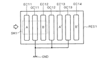
図1は本発明に係る第1の実施の形態のモータ駆動装置の一例を示す概略構成図である。本モータ駆動装置は例えば海上輸送用の冷凍装置に用いられる電子膨張弁や吸入比例弁を駆動することができる。
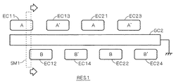
図6は本発明に係る第2の実施の形態のモータ駆動装置の一部を示す概略構成図である。第1の実施の形態に係るモータ駆動装置では、金属片SM1を所定の一方向に移動させながら金属片SM1を導体部と接触させてモータM1を駆動していた。しかしながら、金属片SM1をいくつかの導体部と接触せずに移動させてしまう可能性があった。
D1〜D4 発光ダイオード
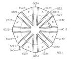
GC1,GC2,GC11〜GC14,GC21〜GC24 導体部
GND 接地
M1 モータ
MD1 モータドライバ回路
SE1〜SE4 電源
SL1〜SL4 信号線
Claims (6)
- 第1電位を供給する第1電位点(SE1〜SE4)に各々接続された第1乃至第Nの信号線(SL1〜SL4)と接続され、前記第1乃至第Nの信号線の各々の電位の変化に基づいて、多相負荷(M1)の各相へ供給する電流を制御する駆動回路と、
前記第1電位が前記第1乃至第Nの信号線の各々を介して供給され、且つ同一の平面上の所定の一方向で配置され、且つ外部と接触可能に露出された第1乃至第Nの導体部(EC11〜EC14,EC21〜EC24)と、
前記第1電位と異なる第2電位を供給する第2電位点(GND)に接続され、且つ前記平面上で前記第1乃至第Nの導体部の各々と所定の間隙を形成して配置され、且つ外部と接触可能に露出し、且つ前記第1乃至第Nの導体部の各々と共に外部の金属片が前記一方向に沿って順次に接触される第(N+1)の導体部(GC1,GC2,GC11〜GC14,GC21〜23)と
を備え、
前記第(N+1)の導体部は、前記一方向において前記第1乃至前記第Nの導体部と交互に配置される、多相負荷駆動装置。 - 第1電位を供給する第1電位点(SE1〜SE4)に各々接続された第1乃至第Nの信号線(SL1〜SL4)と接続され、前記第1乃至第Nの信号線の各々の電位の変化に基づいて、多相負荷(M1)の各相へ供給する電流を制御する駆動回路と、
前記第1電位が前記第1乃至第Nの信号線の各々を介して供給され、且つ同一の平面上の所定の一方向で配置され、且つ外部と接触可能に露出された第1乃至第Nの導体部(EC11〜EC14,EC21〜EC24)と、
前記第1電位と異なる第2電位を供給する第2電位点(GND)に接続され、且つ前記平面上で前記第1乃至第Nの導体部の各々と所定の間隙を形成して配置され、且つ外部と接触可能に露出し、且つ前記第1乃至第Nの導体部の各々と共に外部の金属片が前記一方向に沿って順次に接触される第(N+1)の導体部(GC1,GC2,GC11〜GC14,GC21〜23)と
を備え、
前記第(N+1)の導体部は前記一方向に延在しており、
前記第1乃至第Nの導体部は、前記第(N+1)の導体部の両側又は片側に配置される、多相負荷駆動装置。 - 前記一方向は円周方向の一方向である、請求項1又は2に記載の多相負荷駆動装置。
- 前記第1乃至第Nの導体部の一組は前記一方向に複数配置されている、請求項1乃至3の何れか一つに記載の多相負荷駆動装置。
- 前記第1乃至第(N+1)の導体部の各々は、
金属箔膜と、
前記金属箔膜上に盛られた半田と
を有する、請求項1乃至4の何れか一つに記載の多相負荷駆動装置。 - 前記駆動回路と前記多相負荷との間に接続され、前記各相へと前記電流が供給されたときに、前記各相に対応して発光する発光ダイオード
を更に備える、請求項1乃至5の何れか一つに記載の多相負荷駆動装置。
Priority Applications (2)
| Application Number | Priority Date | Filing Date | Title |
|---|---|---|---|
| JP2007078716A JP4222425B2 (ja) | 2007-03-26 | 2007-03-26 | 多相負荷駆動装置 |
| PCT/JP2008/055244 WO2008117744A1 (ja) | 2007-03-26 | 2008-03-21 | 多相負荷駆動装置 |
Applications Claiming Priority (1)
| Application Number | Priority Date | Filing Date | Title |
|---|---|---|---|
| JP2007078716A JP4222425B2 (ja) | 2007-03-26 | 2007-03-26 | 多相負荷駆動装置 |
Publications (2)
| Publication Number | Publication Date |
|---|---|
| JP2008245355A JP2008245355A (ja) | 2008-10-09 |
| JP4222425B2 true JP4222425B2 (ja) | 2009-02-12 |
Family
ID=39788479
Family Applications (1)
| Application Number | Title | Priority Date | Filing Date |
|---|---|---|---|
| JP2007078716A Expired - Fee Related JP4222425B2 (ja) | 2007-03-26 | 2007-03-26 | 多相負荷駆動装置 |
Country Status (2)
| Country | Link |
|---|---|
| JP (1) | JP4222425B2 (ja) |
| WO (1) | WO2008117744A1 (ja) |
Families Citing this family (1)
| Publication number | Priority date | Publication date | Assignee | Title |
|---|---|---|---|---|
| US10414724B2 (en) * | 2014-10-09 | 2019-09-17 | Toray Industries, Inc. | Photochemical reaction device, photochemical reaction method using same, and lactam production method using said method |
Family Cites Families (3)
| Publication number | Priority date | Publication date | Assignee | Title |
|---|---|---|---|---|
| DE3541275A1 (de) * | 1985-11-22 | 1987-05-27 | Heidelberger Druckmasch Ag | Steuerschaltung fuer einen elektrischen druckmaschinenantriebsmotor oder dergleichen |
| JPS6328283A (ja) * | 1986-07-18 | 1988-02-05 | Diesel Kiki Co Ltd | モ−タ制御用スイツチ |
| FR2688620B1 (fr) * | 1992-03-10 | 1994-10-21 | Thomson Csf | Dispositif de transmission d'energie de commande mecanique, notamment pour le controle de la pression de freinage dans un frein. |
-
2007
- 2007-03-26 JP JP2007078716A patent/JP4222425B2/ja not_active Expired - Fee Related
-
2008
- 2008-03-21 WO PCT/JP2008/055244 patent/WO2008117744A1/ja not_active Ceased
Also Published As
| Publication number | Publication date |
|---|---|
| JP2008245355A (ja) | 2008-10-09 |
| WO2008117744A1 (ja) | 2008-10-02 |
Similar Documents
| Publication | Publication Date | Title |
|---|---|---|
| KR100984604B1 (ko) | 리니어 모터 시스템 | |
| US20130285584A1 (en) | Motor driving apparatus and method | |
| JP4623150B2 (ja) | モータ制御装置 | |
| JP2008141948A (ja) | 電圧源インバータの損失を低減するためのpwmパターン・シーケンス | |
| CN110679067B (zh) | 驱动装置一体型旋转电机以及电动助力转向装置 | |
| JP2009089519A (ja) | 車載空気調和機用インバータシステム | |
| JP2016001945A (ja) | モータ制御装置、及びそれに用いる誤配線検出方法 | |
| JP2009005530A (ja) | ブラシレスモータ用プリント基板およびブラシレスモータ | |
| JP4222425B2 (ja) | 多相負荷駆動装置 | |
| EP1926202B1 (en) | Power conversion apparatus | |
| JP5783802B2 (ja) | モータ駆動装置、集積回路装置、モータ装置、及びモータ駆動システム | |
| JP2008161019A (ja) | リニアモ−タ装置及びこれを用いた露光装置 | |
| JP5055042B2 (ja) | 回転角度検出装置及びこれを用いた電動機駆動装置 | |
| JP2009130990A (ja) | 複数の電動機の駆動装置及び該装置の制御方法 | |
| WO2022197413A1 (en) | Electrical machines with segmented inverter components | |
| RU2392730C1 (ru) | Электрический следящий привод | |
| JP2017208878A (ja) | インバータ装置 | |
| JP3259441B2 (ja) | 誘導電動機のベクトル制御装置 | |
| JP2004168487A (ja) | エレベータ | |
| JP2020096437A (ja) | 冗長アクチュエータシステム | |
| US9312787B2 (en) | Inverter with series connected gate driving circuits and voltage divider | |
| JP4111002B2 (ja) | モータ制御装置 | |
| JP2000238989A (ja) | 移動機械の運転制御装置 | |
| JP2017017953A (ja) | 巻線切替システムおよびリニアモータ | |
| US7923952B2 (en) | Device for controlling polyphase rotating machine |
Legal Events
| Date | Code | Title | Description |
|---|---|---|---|
| A521 | Request for written amendment filed |
Free format text: JAPANESE INTERMEDIATE CODE: A523 Effective date: 20080707 |
|
| A131 | Notification of reasons for refusal |
Free format text: JAPANESE INTERMEDIATE CODE: A131 Effective date: 20080805 |
|
| A521 | Request for written amendment filed |
Free format text: JAPANESE INTERMEDIATE CODE: A523 Effective date: 20081001 |
|
| TRDD | Decision of grant or rejection written | ||
| A01 | Written decision to grant a patent or to grant a registration (utility model) |
Free format text: JAPANESE INTERMEDIATE CODE: A01 Effective date: 20081028 |
|
| A01 | Written decision to grant a patent or to grant a registration (utility model) |
Free format text: JAPANESE INTERMEDIATE CODE: A01 |
|
| A61 | First payment of annual fees (during grant procedure) |
Free format text: JAPANESE INTERMEDIATE CODE: A61 Effective date: 20081110 |
|
| R151 | Written notification of patent or utility model registration |
Ref document number: 4222425 Country of ref document: JP Free format text: JAPANESE INTERMEDIATE CODE: R151 |
|
| FPAY | Renewal fee payment (event date is renewal date of database) |
Free format text: PAYMENT UNTIL: 20111128 Year of fee payment: 3 |
|
| FPAY | Renewal fee payment (event date is renewal date of database) |
Free format text: PAYMENT UNTIL: 20121128 Year of fee payment: 4 |
|
| FPAY | Renewal fee payment (event date is renewal date of database) |
Free format text: PAYMENT UNTIL: 20121128 Year of fee payment: 4 |
|
| FPAY | Renewal fee payment (event date is renewal date of database) |
Free format text: PAYMENT UNTIL: 20131128 Year of fee payment: 5 |
|
| LAPS | Cancellation because of no payment of annual fees |


