JP4221199B2 - Machine and method for processing a workpiece of wood or plastic material - Google Patents

Machine and method for processing a workpiece of wood or plastic material Download PDF

Info

Publication number
JP4221199B2
JP4221199B2 JP2002226126A JP2002226126A JP4221199B2 JP 4221199 B2 JP4221199 B2 JP 4221199B2 JP 2002226126 A JP2002226126 A JP 2002226126A JP 2002226126 A JP2002226126 A JP 2002226126A JP 4221199 B2 JP4221199 B2 JP 4221199B2
Authority
JP
Japan
Prior art keywords
unit
workpiece
machine
wooden article
advance
Prior art date
Legal status (The legal status is an assumption and is not a legal conclusion. Google has not performed a legal analysis and makes no representation as to the accuracy of the status listed.)
Expired - Fee Related
Application number
JP2002226126A
Other languages
Japanese (ja)
Other versions
JP2003080434A (en
JP2003080434A5 (en
Inventor
グルカ パウル
Original Assignee
ミヒャエル ヴァイニヒ アクチエンゲゼルシャフト
Priority date (The priority date is an assumption and is not a legal conclusion. Google has not performed a legal analysis and makes no representation as to the accuracy of the date listed.)
Filing date
Publication date
Family has litigation
First worldwide family litigation filed litigation Critical https://patents.darts-ip.com/?family=7694094&utm_source=google_patent&utm_medium=platform_link&utm_campaign=public_patent_search&patent=JP4221199(B2) "Global patent litigation dataset” by Darts-ip is licensed under a Creative Commons Attribution 4.0 International License.
Application filed by ミヒャエル ヴァイニヒ アクチエンゲゼルシャフト filed Critical ミヒャエル ヴァイニヒ アクチエンゲゼルシャフト
Publication of JP2003080434A publication Critical patent/JP2003080434A/en
Publication of JP2003080434A5 publication Critical patent/JP2003080434A5/ja
Application granted granted Critical
Publication of JP4221199B2 publication Critical patent/JP4221199B2/en
Anticipated expiration legal-status Critical
Expired - Fee Related legal-status Critical Current

Links

Images

Classifications

    • BPERFORMING OPERATIONS; TRANSPORTING
    • B27WORKING OR PRESERVING WOOD OR SIMILAR MATERIAL; NAILING OR STAPLING MACHINES IN GENERAL
    • B27CPLANING, DRILLING, MILLING, TURNING OR UNIVERSAL MACHINES FOR WOOD OR SIMILAR MATERIAL
    • B27C1/00Machines for producing flat surfaces, e.g. by rotary cutters; Equipment therefor
    • B27C1/12Arrangements for feeding work
    • BPERFORMING OPERATIONS; TRANSPORTING
    • B27WORKING OR PRESERVING WOOD OR SIMILAR MATERIAL; NAILING OR STAPLING MACHINES IN GENERAL
    • B27FDOVETAILED WORK; TENONS; SLOTTING MACHINES FOR WOOD OR SIMILAR MATERIAL; NAILING OR STAPLING MACHINES
    • B27F1/00Dovetailed work; Tenons; Making tongues or grooves; Groove- and- tongue jointed work; Finger- joints
    • B27F1/02Making tongues or grooves, of indefinite length
    • BPERFORMING OPERATIONS; TRANSPORTING
    • B27WORKING OR PRESERVING WOOD OR SIMILAR MATERIAL; NAILING OR STAPLING MACHINES IN GENERAL
    • B27MWORKING OF WOOD NOT PROVIDED FOR IN SUBCLASSES B27B - B27L; MANUFACTURE OF SPECIFIC WOODEN ARTICLES
    • B27M1/00Working of wood not provided for in subclasses B27B - B27L, e.g. by stretching
    • B27M1/08Working of wood not provided for in subclasses B27B - B27L, e.g. by stretching by multi-step processes
    • YGENERAL TAGGING OF NEW TECHNOLOGICAL DEVELOPMENTS; GENERAL TAGGING OF CROSS-SECTIONAL TECHNOLOGIES SPANNING OVER SEVERAL SECTIONS OF THE IPC; TECHNICAL SUBJECTS COVERED BY FORMER USPC CROSS-REFERENCE ART COLLECTIONS [XRACs] AND DIGESTS
    • Y10TECHNICAL SUBJECTS COVERED BY FORMER USPC
    • Y10TTECHNICAL SUBJECTS COVERED BY FORMER US CLASSIFICATION
    • Y10T83/00Cutting
    • Y10T83/647With means to convey work relative to tool station
    • Y10T83/654With work-constraining means on work conveyor [i.e., "work-carrier"]
    • Y10T83/6542Plural means to constrain plural work pieces

Landscapes

  • Life Sciences & Earth Sciences (AREA)
  • Engineering & Computer Science (AREA)
  • Mechanical Engineering (AREA)
  • Wood Science & Technology (AREA)
  • Forests & Forestry (AREA)
  • Milling, Drilling, And Turning Of Wood (AREA)
  • Jigs For Machine Tools (AREA)
  • Feeding Of Workpieces (AREA)
  • Chemical And Physical Treatments For Wood And The Like (AREA)
  • Turning (AREA)
  • Specific Conveyance Elements (AREA)
  • Dovetailed Work, And Nailing Machines And Stapling Machines For Wood (AREA)
  • Sawing (AREA)

Abstract

The machine tool machines workpieces (3). It has a longitudinal shaping unit (2) with at least one spindle. The workpiece is taken past this by a feeder (15), clamped in clamping jaws. At least some of the upper clamping jaws rest on interstices of the lower clamping jaws when seen in plan view, leaving a small free space for adjustment.

Description

【0001】
【発明の属する技術分野】
本発明は、請求項1の前文(所謂プレアンブル部分)に係る、木材やプラスチック材料の工作物(ワークピース)を加工するための機械と、こうした工作物を加工する、請求項24,26,28,32の前文に係る方法とに関する。
【0002】
【従来の技術】
こうした装置を用いて、工作物を加工して、窓及びドアのフレーム、ならびに窓の羽根を製造している。長手方向プロファイル形成ユニットでは、工作物の長手方向側部に沿ってプロファイルを形成する。長手方向プロファイル形成ユニット内に工作物を搬送するために、支持部から吊り下げられ、回転可能に駆動される前進ローラが設けられている。この前進ローラを、テーブル表面上に支持さている工作物に押し付けることにより、このローラを利用して工作物を装置内に搬送する。この前進ローラは磨耗及び汚染し易いため、工作物の搬送がうまく実行できなくなる。さらに、工作物の長さが短い場合には、その搬送に問題が起きる。
【0003】
【発明が解決しようとする課題】
工作物の信頼性の高い簡単な搬送ならびに正確な位置付けを確実に行なうことのできるように、上述の機械と上述の方法とを提供することが本発明の一目的である。
【0004】
【課題を解決するための手段】
この目的を、請求項1の特徴構成を有する上述の機械と、請求項24の特徴構成を有する上述の方法についての本発明によって実現する。
【0005】
本発明による装置において、長手方向プロファイル形成ユニットにおける前進ユニットは、加工する工作物をクランプするだけでなく、工作物をその長手方向プロファイル形成ユニット内に搬送するクランプユニットの形態である。本発明によるこの前進ユニットがあるため、長手方向プロファイル形成ユニット内に前進ローラは不要である。加工する工作物は、このクランプユニットと高い信頼性で係合されて、一緒に装置内を搬送される。前進ローラの場合には見られがちであったスリップの問題は起こらない。このクランプユニットを用いると、工作物の頂部側の取扱いが優しくなるため、優れた加工品質が得られる。このクランプユニットにより、長さが非常に短い工作物のクランプ及び加工も可能となる。このクランプユニットは長手方向プロファイル形成ユニット内を移動するため、この装置の軸を利用して、工作物に対する追随、測定及び位置付けを大変正確に行なうことができる。この接続には、従来の装置で使用されていたリミットスイッチは必要ない。工作物の上及び下にクランプジョーを配置して、上下からその工作物をクランプする。こうすることにより、対応工具により、工作物の長手方向側を問題なく加工することができる。この上部及び下部のクランプジョーを、平面図において、互いに位置をずらし、間に僅かな空間があるように配置する。クランプユニットをこうして構成することにより、工作物を例外なく、柔軟に、高い信頼性でクランプすることができる。こうして、工作物、特に、薄く短い工作物をも、優れた精度及び品質でクランプ位置にて加工することができる。各加工処理間における工作物の移送時も、工作物をクランプしたままの状態であるため、大変正確な加工を確実に行なうことができる。
【0006】
本発明のさらなる特徴は、特許請求の範囲、明細書、及び図面により明白になるであろう。
【0007】
【発明の実施の形態】
以下に、図面に例示した一実施形態により本発明を説明することとする。
【0008】
以下に記載する装置は、例えば、窓やドアのフレームあるいはネットワークを組み立てるために使用する、木製物品の加工用である。しかしながら、この装置を、階段のステップ、フレーム構造や箱構造などの家具部品に用いる木製物品の加工に用いることも可能である。図1による装置には、横方向プロファイル形成ユニット1と、そのユニット1に直角に配置された長手方向プロファイル形成ユニット2とがある。この横方向プロファイル形成ユニット1で、木製物品3の端面を加工する。続いて、長手方向プロファイル形成ユニット2で木製物品の長手方向側のプロファイルを形成する。
【0009】
加工する木製物品3を、往復台5’上で垂直軸6を中心に枢動可能なクランプ装置4により、横方向プロファイル形成ユニット1内の予め定められた位置、好ましくは中央にクランプする。この往復台5’は、ガイド7方向に移動可能な横方向の往復台5に沿って移動可能である。どちらの往復台5及び5’も、垂直方向に互いに調整可能である。
【0010】
横方向プロファイル形成ユニットに、木製物品3の各端部を切断することのできる少なくとも1つの鋸8を設ける。この鋸8に対する木製物品3の位置に依存して、木製物品3の複数の端面を鉛直に、しかし、木製物品の長手方向に対しては鋭角あるいは鈍角に切ることができる。この場合、木製物品3を、所望の角度に軸6を中心にクランプ装置4により枢動する。これを目的として、クランプ装置4を自動的に所望位置内に枢動させられるようにモータードライブ(図示せず)を設ける。有利なことに、このクランプ装置4はCNC制御装置に接続可能である。
【0011】
鋸8には、水平軸を中心に回転する円形鋸歯9がある。鋸8の下流では、横方向プロファイル形成ユニット1に、従来技術では周知であるように、ほぞ/ほぞ穴工具11が固定着座している少なくとも1つの鉛直スピンドル10を設ける。この工具により、鋸で切断した木製物品3の端部の横方向に、例えばほぞやほぞ穴あるいは相手方形状を施して、プロファイルを形成する。従来技術で周知のように、工具11を備えたスピンドル10は軸方向に調節可能である。本発明では、木製物品3の端部を所望通りに加工することができるように、スピンドル10に互いに上下に2つ以上の工具を着座させる。さらに、スピンドル10を各工具11のさまざまな直径に適合させられるように、スピンドル10を半径方向に調節することもできる。例示した実施形態に示すように、横方向プロファイル形成ユニット1に、追加工具11用の第2のスピンドル10を設けることができる。この第2のスピンドル10は後退しているため、使用状態にはない。このスピンドル10を後退させる代わりに、クランプ装置4を横方向往復台5上で往復台5’により後退させることもできる。
【0012】
スピンドル10の下流には、横方向プロファイル形成ユニット1に、少なくとも1つのドリル及び/又はだぼ継ぎユニット12を設ける。このユニットにより、横方向プロファイル形成処理の後、木製物品3に少なくとも1つの穴及び/又は少なくとも1つのだぼを設けることができる。
【0013】
横方向プロファイル形成ユニット1には、鋸8及び/又はスピンドル10及び/又はユニット12のみを備えることもできる。
【0014】
横方向の往復台5は、図1に例示した初期位置から矢印13の方向にガイド7に沿って移動する。往復台が移動すると、クランプされている木製物品3のまず両端部が鋸8により連続的に切断され、引き続き横断方向のプロファイルを形成され、穿孔及び/又はだぼを設けられる。装置の構成に依存して、横方向の往復台5はその搬送方向14を戻って初期位置に復帰し、クランプ装置4は垂直軸6を中心に枢動して、その木製物品3を横方向プロファイル形成ユニット1内に新たに通過させることにより、その木製物品3の他方の端部を鋸で切断し、横方向のプロファイルを形成することができる。この場合、長手方向プロファイル形成ユニット2に移送する前に、木製物品3の両端部をまず加工する。この処理シーケンスを図2に例示する。木製物品3を、説明した方法で横方向プロファイル形成ユニット1内に2回搬送して、両端部を加工する。両端部を加工した木製物品3は、その後長手方向プロファイル形成ユニット2に移送されて、以下に説明するようにその長手方向のプロファイルを形成される。
【0015】
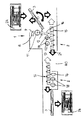
横方向の往復台5が移送位置に到着すると、クランプ装置4が回転して、木製物品を長手方向プロファイル形成ユニット2内の搬送方向と平行に位置付ける。この位置で、長手方向プロファイル形成ユニット2の前進ユニット15が木製物品を収容することができる。木製物品3はこのユニットにより、長手方向プロファイル形成ユニット内の長手方向に搬送され、この通過時に対応する長手方向側を加工される。図1による装置では、木製物品3の搬送方向から見て、長手方向プロファイル形成ユニット2に、まずドリルユニット16が、次に少なくとも1つの長手方向プロファイル形成工具18が固定着座した少なくとも1つの鉛直スピンドル17が設けられている。例示した実施形態において、長手方向の型彫ユニット2には2つのスピンドル17が設けられており、それぞれに少なくとも1つの長手方向プロファイル形成工具18が固定着座している。ドリルユニット16により、木製物品3の搬送方向右に位置する長手方向側、ならびに頂部及び/又は底部に穴を加工する。長手方向プロファイル形成工具18により、木製物品3の搬送方向右の長手方向側にプロファイルを形成する。長手方向プロファイル形成ユニット2にさらにスピンドルを追加することができる。図1には、第2の長手方向プロファイル形成スピンドル17と、その背後の水平ほぞスピンドル84とを例示している。
【0016】
図2は、上述したように木製物品3を横方向プロファイル形成ユニット1内に2回通過させてその両端部を連続して加工する装置の第1の実施形態を示している。この後、木製物品3は前進ユニット15に移送され、木製物品はこれと共に移動して、長手方向プロファイル形成ユニット2のドリルユニット16ならびに2つの長手方向プロファイル形成工具18を通過する。長手方向プロファイル形成工具18及びドリルユニット16は、上述したように、木製物品3が通過すると、その右長手方向側を加工するように配置されている。この装置では、長手方向プロファイル形成工具18の下流に、別の長手方向プロファイル形成工具18ならびにドリルユニット16を追加して備えた第2の長手方向プロファイル形成ユニット2が設けられている。これらは、木製物品3が通過すると、その左長手方向側を加工するように配置されている。こうすることにより、木製物品3が長手方向プロファイル形成ユニット2を1回通過して、装置全体を貫通するだけで加工が完了する。両方の長手方向側を加工された木製物品3は、長手方向プロファイル形成ユニット2内の搬送方向21に垂直な搬送ユニットにより、別のステーションあるいは付随したマガジン24に供給される。この装置は、木製物品3が装置内を通過して連続的に加工される連続型装置の代表例である。木製物品3は、その加工処理中いかなる時も、横方向及び長手方向プロファイル形成ユニット1及び2に固定してクランプされているため、最適な加工品質及び加工精度を実現することができる。
【0017】
図3による本装置の第2の実施形態では、長手方向プロファイル形成ユニット2を通過した木製物品3を、横方向コンベヤ20上に移動して、横方向プロファイル形成ユニット1に返送する。この装置の2種類の加工操作について、以下に図3を参照しながら詳述する。第1の加工シーケンスによれば、木製物品3は、上述したように横方向プロファイル形成ユニット1内の搬送方向13にまず搬送される。円形鋸8の円形鋸歯9により、木製物品3の対応端部が切断され、その下流の工具11により、例えばほぞあるいはほぞ穴を設けられて、横方向のプロファイルを形成される。続いて、ドリル及び/又はたぼ継ぎユニット12により、木製物品3に穿孔及び/又はだぼを施す。その後、木製物品3を長手方向プロファイル形成ユニット2の前進ユニット15に移送する。長手方向プロファイル形成ユニットでは、木製物品3の長手方向側、ならびに頂部及び/又は底部にドリルユニット16で穿孔する。続いて、互いに間隔をおいて前後に配置されている2つの長手方向プロファイル形成工具18の少なくともの一方で、その一方の長手方向側のプロファイルを形成する。こうして一方の端部及び一方の長手方向側を加工された木製物品3は、横方向コンベヤ20に到達し、これにより長手方向プロファイル形成ユニット2内において、搬送方向21に垂直な搬送方向22に搬送される。この横方向コンベヤ20により、木製物品3を、前進ユニット15に平行に配置されており、横方向プロファイル形成ユニット1に木製物品3を返送する搬送ユニット23に移送する。ここで、この木製物品3はクランプ装置4に収容されて、木製物品3のまだ加工されていない他方の端部を鋸8で切断し、ほぞやほぞ穴を設けるなど工具11により横方向のプロファイルを形成し、任意に、ドリル及び/又はだぼ継ぎユニット12で加工できるように位置合わせされる。こうして両端部を加工された木製物品3を、木製物品3のまだ加工されていない長手方向側がドリルユニット16及び2つの長手方向プロファイル形成工具18を通過するように、長手方向プロファイル形成ユニット2の前進ユニット15に移送する。必要に応じて、ドリルユニット16により、木製物品3のこの長手方向側を穿孔する。次に、この木製物品3の長手方向のプロファイルを、垂直軸を中心に回転自在な下流工具18により形成する。
【0018】
横方向プロファイル形成ユニット1における第2の好適加工操作では、横方向往復台5が上述したように横方向プロファイル形成ユニット1内を2回移動して、木製物品3の両端物品をまず加工する。次に、両端部を加工した木製物品3を、図1に例示した移送位置にある前進ユニット15に移送する。この前進ユニット15の移動により、木製物品3はドリルユニット16及び長手方向プロファイル形成工具14を通過して、その長手方向側を加工される。横方向コンベヤ20及び搬送装置23により、木製物品は横方向プロファイル形成ユニット1に返送され、クランプ装置4に収容される。木製物品3は横方向往復台5と共に、加工されることなく横方向プロファイル形成ユニット1を通過し、前進ユニット15に移送されて、長手方向プロファイル形成ユニットを通過すると同時に、他方の長手方向側を加工される。
【0019】
木製物品が横方向コンベヤ20により搬送ユニット23に搬送されている間、前進ユニット15は移送位置に復帰して、この木製物品を直ちに受け取ることができるようにする。
【0020】
図3による装置は、木製物品が装置内を2回搬送される円形装置の代表例である。木製物品3がこの装置内を2回通過した後、加工された木製物品に次の加工を施すために横方向コンベヤ20に移動させてもよい。しかしながら、この木製物品3を横方向コンベヤ20に移送した後、搬送装置23に移送して、加工済木製物品3をマガジン24(図3)に挿入することも可能である。
【0021】
図7〜図11に例示するように、横方向プロファイル形成ユニット1内において2つの木製物品を同時に加工することができる。2つの木製物品3を互いの長手方向側を当接させながら位置付けて、クランプ装置4内にクランプする。このクランプ装置4は、バイスグリップクランプ装置の形態であり、下部クランプジョー25及び上部クランプジョー26とがある。木製物品3を、この2つのクランプジョー25と26との間にクランプする。クランプジョー25及び26には、平坦な支持表面27及び28があるため、これを用いて木製物品を高い信頼性でクランプすることができる。上部クランプジョー26は、鉛直方向29に調節可能である(図8)。上述したように、クランプ装置4全体は、矢印13の方向である、木製物品3の軸に対して横方向に調節可能である。
【0022】
下部クランプジョー25の自由端に、上方に延出する止め子31を設け、これにより、木製物品3のクランプジョー25及び26に対する横方向の摺動を防止し、木製物品3の正確な整合あるいは位置付けを確実にする。クランプジョー25は、その長手方向を横断する水平軸32を中心に枢動可能である。以下に説明するように木製物品3が長手方向プロファイル形成ユニット2の前進ユニット15に移送されると、クランプジョー25は、止め子31が木製物品3の移動路から外れるように、下方方向の解放位置まで軸32を中心に枢動することができる(図8)。
【0023】
図7に、木製物品3を、横方向プロファイル形成ユニット1のクランプ装置4から長手方向プロファイル形成ユニット2の前進ユニット15内に移送する初期位置を示す。この初期位置では、クランプ装置4と前進ユニット15とは離間している。クランプ装置4と前進ユニット15との間の領域に、中間クランプ装置33が設けられている。この装置には、2つのクランプジョー35及び34が互いに上下に配置されており、この少なくとも一方が鉛直方向に調節可能である。また、この中間クランプ装置33全体も鉛直方向に調節可能である。中間クランプ装置33の下方領域には、移送ユニット36が設けられており、これには、互いに間隔をおいて上下に配置された2本のエンドレス循環ベルト37及び38が含まれている。このベルトは、支持要素39及び40上でそれぞれ支持されており、この支持要素の少なくとも一方が鉛直方向に調節可能となっている。こうすることにより、2本のベルト37と38との間の空間を、搬送する木製物品3の厚さに簡単に調節することができる。また、移送ユニット36全体も鉛直方向に調節可能である。
【0024】
木製物品3をクランプ装置4から前進ユニット15に移送するには、まず、クランプ装置4を、中間クランプ装置33に対してその調節方向30に調節する。クランプ装置33の2つのクランプジョー34及び35を、木製物品3をクランプジョー34と35との間で高い信頼性で移動できるように調節する。クランプ装置33を、クランプ装置4あるいはそのクランプジョー25及び26の調節路から外れた領域内に位置付ける。クランプ装置4を、クランプ装置33のクランプジョー34と35との間に木製物品3を完全に配置できるまで調節する(図8)。クランプジョー34と35との間に木製物品3が移動すると同時に、クランプジョーの一方、この実施形態では上部クランプジョー34を木製物品3に向けて移動して、木製物品3を高い信頼性でクランプ装置33のクランプジョー34と35との間にクランプする(図8)。その後、クランプ装置4の下部クランプジョー25を、下部クランプジョー25の止め子31が木製物品3の下方領域に位置するまで、軸32を中心に下方に枢動させる。ここでクランプ装置4を矢印41の方向に返送することができる。これは、クランプ装置4が配置されている横方向往復台5を対応して復帰させることで実行される。
【0025】
木製物品3をクランプ装置4から中間クランプ装置33に移送する間、移送ユニット36はまだ、中間装置33の下方領域である初期位置にある(図8)。クランプ装置4が復帰すると同時に、この移送ユニット36は図9に例示する移送位置に移動する。この移動を行なうには、移送ユニット36をまず、矢印42の方向に下方位置に後退させて、移送ユニット36を鉛直方向(図8の矢印43)に引き続き調節している間に、前進ユニット15とは反対側である中間クランプ装置33の側部にて、ベルト37及び38を木製物品3の高さまで上方に移動させる必要がある。この接続時、移送ユニット36を中間クランプ装置33の方向に引き続き調節する時点で、木製物品3が2つのベルト37と38との間に移動するように、2本のベルト37と38との間には間隔が開いている(図9)。2本のベルト間の間隔を、移送ユニット36を移送位置内に調節しても、木製物品3に接触しないように調節する。図9に例示した移送位置に到達すると同時に、移送ユニット36に含まれる支持要素39及び40の少なくとも一方を、木製物品3をベルト37と38との間にクランプできるように調節する。
【0026】
ベルト37及び38をこのように調節したら、木製物品を解放できるように中間クランプ装置33のクランプジョー34及び35を開く。次に、木製物品3をクランプしている移送ユニット36を矢印30(図9)の方向に後退させて、中間クランプ装置33のクランプジョー34及び35を木製物品3の外部領域に外す。外した後、中間クランプ装置33を下方に移動させる(図10)。
【0027】
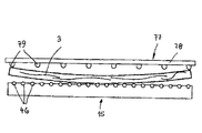
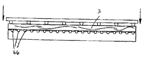
中間クランプ装置33を木製物品3の外部領域に外すと同時に、移送ユニット36を矢印30(図9)とは反対方向に移動して前進ユニット15に近づける。次に、木製物品3を長手方向プロファイル形成ユニット2の前進ユニット15内に運搬する摺動型搬送ユニット77を運搬方向44(図10)に移動する。移送ユニット36のエンドレス循環ベルト37及び38で木製物品3を挟み、木製物品3の移動に同調させる。ベルト37及び38は、木製物品3を案内し、この移送処理時の軸方向の移動を防止する役割を果たす。木製物品3の運搬方向44(図10)は、その長手方向軸に垂直に位置している。前進ユニット15には、以下に説明するように、その長手方向全体に一様にクランプジョーが設けられており、これにより、木製物品3は支持部45上にクランプされる。調節方向44における木製物品3の移動路は、前進ユニット15の長手方向全体に設けられ、木製物品3が当接する複数の止め子46により限定されている。
【0028】
横方向のプロファイル形成時とは違い、長手方向プロファイル形成時には2つの木製物品3を互いに隣接して配置することができないため、一方の木製物品3のみをまず前進ユニット15内に搬送する。木製物品3が止め子46に接触すると同時に、クランプジョーが下方に移動して、この木製物品3を前進ユニット内15にクランプする。その後、この前進ユニット15が、次の木製物品3が搬送ユニット77により前進ユニット15内に同じように搬送されてクランプされるまで、前進方向21(図2及び図3)に移動する。図11に、前進ユニット15が前方に移動しており、第2の木製物品3をその前進ユニット15内に搬送した状態を示す。
【0029】
この第2の木製物品3を前進ユニット15内にクランプした後、輸送ユニット36を前進方向42(図8)と逆の方向に後退させることができるように、輸送ユニット36の上方支持要素39を上方に移動する。次に、移送ユニット36を次の移送サイクルに利用できるようにするために、この位置を再度降下させる。加工する木製物品3が長い場合には、一定の対応長さについて前進ユニット15内に1つの木製物品しかクランプできない。長手方向プロファイルを形成した木製物品3の移送後、往復台5は移送位置で、前進ユニット15が移送領域内に復帰するまで待たなくてはならない。
【0030】
木製物品の幅に依存して、横方向プロファイル形成ユニット1のクランプ装置4には、1つの木製物品3しか収容できない場合も、2つ以上の木製物品3を収容できる場合とがある。木製物品3の幅がクランプ装置4のクランプ要素と同じ幅であれば、クランプ装置4には1つの木製物品3しか収容できず、これを横方向プロファイル形成ユニット1内で加工した後、上述したように前進ユニット15に移送する。木製物品の幅がかなり狭ければ、クランプ装置4には、3個以上の木製物品3を互いに当接させてクランプすることができる。木製物品3及び前進ユニット15の長さに依存して、前進ユニット15内に連続的にクランプすることができる。前進ユニット15の長さが木製物品3のすべてを前後に連続してクランプするほどに長くない場合、長手方向プロファイル形成ユニット2内に収容された木製物品の加工が終了して前進ユニット15がその移送位置に復帰してから、残りの木製物品3を行なう。こうして、残りの木製物品3を、上述したように前進ユニット15に移送することができる。
【0031】
木製物品3が中間クランプ装置33内にクランプされているうちに、有利なことに横方向プロファイル形成ユニット1のドリルユニット12により、必要に応じて、その木製物品3に穴を加工する。この穿孔処理の間に、クランプ装置4を、次の工作物を受け取るように初期位置に復帰させることができる。
【0032】
図4〜図6及び図14を参照しながら、以下に前進ユニット15について詳述する。この前進ユニット15には、有利なことにその長さ方向全体に延在するキャリア47が具備されている。キャリア47には、複数のガイド要素49をその長さ方向に分散して固定した鉛直な背面壁部48が設けられている。このガイド要素49は、互いに間隔をあけながら2本の水平な列をなして配置されている(図4、図5及び図14)。このガイド要素49により、前進ユニット15は、機械フレーム(図示せず)上に設けられた2本の平行なガイドレール50及び51(図14)上に位置を定めて置かれる。
【0033】
キャリア47の背面壁部48の上端部には、それに垂直に位置を定めて置かれている支持部52への移行部分がある。その下側に、クランプジョー54用に少なくとも1つの駆動装置53を装着する。有利なことにこの駆動装置53には、その水平なキャリア部分52の下側に固定され、下向きにピストンロッド57を延在させたリフトシリンダ56(図14)が具備されている。このシリンダの下方端部は、横方向部材58により上向きのロッド形状キャリア59に接続されている。この上向きのロッド形状キャリア59は、少なくとも1つのガイド60ならびにガイドブッシング61を貫通し、支持部52を通過して上方に突出しており、各クランプジョー54を上方自由端にて支持している。こうすることにより、クランプジョー58すべてが、鉛直方向においてリフトシリンダ56により互いに無関係にそれぞれ調節可能となる。つまり、各クランプジョー54をそれぞれ別々に調節することができる。また、クランプジョー54をグループに分けて、グループ毎に一緒に調節することも可能である。
【0034】
少なくとも1つの熊手型支持部62を、木製物品3用の止め子46を支持している支持部52上で支持する。有利なことに、この止め子46は、クランプジョー54及び55に向き合っている支持部62の頂部側を垂直に貫通し、この止め子46を止め位置まで軸方向に移動させる少なくとも1つの圧力バネ63の力を受ける止めボルトである。
【0035】
平面図(図6)を参照すると、クランプジョー54には、長手方向のクランプ縁部に矩形の突起部65を備えた四角形の基部部材64がある。この矩形部分により、クランプジョー54の突起部65の両側に、矩形凹部66及び67がある。クランプジョー54すべての形状は同一であり、一定間隔をおきながら隣接して一列に位置を定めて置かれている。有利なことに、必要に応じて、簡単かつ迅速に交換することができるように、このクランプジョー54をキャリア59の上端部にネジで取付ける。
【0036】
クランプジョー54は、クランプジョー55に対向して鉛直方向に位置を定めて置かれている。クランプジョー55の上部側68が、木製物品3をクランプするための支持部45(図10)を形成している。クランプジョー55はすべて同じ高さであり、有利なことに、その高さは、鉛直方向に互いに無関係にある程度まで調節可能である。しかしながら、この下部クランプジョー55をすべて一緒あるいはグループ毎に鉛直方向に調節することもできる。この調節は、シリンダにより実現可能である。しかしながら、クランプジョー55の調節はCNC軸によっても実行可能である。
【0037】
図6に例示しているように、クランプジョー55は、前進ユニット15に対する平面図で見た場合に、クランプジョー54に対して位置をずらして配置されている。下部クランプジョー55には、平面図で見た場合に、隣り合うクランプジョー54との間に矩形脚部69のあるT型形状部分がある。さらに下部クランプジョー55には、その脚部69に直角に位置を定めて置かれた横棒70が設けられている。この横棒70は、平面図で見た場合に、隣り合う下部クランプジョー54の凹部66及び67内に配置されている。各クランプジョー54と55との間には、平面図で見た場合に、わずかに空間がある。この空間により、以下に説明するように、上部クランプジョー54を、問題も接触の危険性もなく、下部クランプジョー55との間で下向きに移動させることができる。
【0038】
下部クランプジョー55は、クランプジョー55をリフトシリンダ72に接続している脚部71(図14)から横方向に突出している。このリフトシリンダ72により、図7〜図11を参照しながら以下に説明するように、木製物品3を横方向プロファイル形成ユニットの後に前進ユニット15に移送したら、下部クランプジョー55を下降させることができる。このリフトシリンダ72は、キャリア47上で支持されている。
【0039】
熊手型支持部62には、水平方向に突出する複数の指当て部分73(図4及び図14)がある。これらは、互いに間隔をあけて配置されており、その空間内に、上部クランプジョー54用のロッド形状キャリア59ならびに下部クランプジョー55の脚部71が突出している。支持部62には、止め子31の圧力バネ63をその一方の端部で支持し、互いに間隔をおいて位置を定めて置かれた直立支持部74が設けられている。クランプする木製物品3の断面形状に止め子46の位置を適合させるために、熊手型支持部62を、キャリア47の支持部分52上で矢印75の方向に水平に調節することができる。この調節用に具備された駆動装置は例示していない。熊手型支持部62を手動で調節することも可能である。有利なことに、支持部62を制御しながら調節して、加工する木製物品3の断面形状に対する止め子46の自動調節を確実に行なうことができる。
【0040】
前進ユニット15にも、2つ以上の隣接した支持物品62を設けることができる。これらは有利なことに、上述したように、加工対象である幅の異なる数個の木製物品を互いに前後してクランプするように、互いに別々に調節可能である。
【0041】
図7〜図11と合わせて説明してきたように、木製物品3は、横方向プロファイル形成ユニット1から長手方向プロファイル形成ユニット2の前進ユニット15に直接移送されるのではなく、移送ユニット36により移送される。移送位置(図9)において、前進ユニット15に対して、移送ユニット36のベルト37及び38の、前進ユニット15のクランプジョー54及び55に対する空間が最小限になるように、移送ユニット36を配置する。こうすることにより、木製物品3を問題なく移送ユニット36から前進ユニット15内に搬送することができる。木製物品3の移送を阻害せず最適な状態で行なうため、木製物品を移送する前に、下部クランプジョー55を、下部クランプジョー55の支持部側68が移送ユニット36の下方ベルト38の支持平面下に位置するまで最小限だけ下降させる。こうすることにより、前進ユニット15の2つのクランプジョー54、55の間に木製物品3を問題なく搬送することができる。
【0042】
木製物品3を移送する前に、熊手型支持部62を移動方向75に対応移動させることにより、止め子46を所望位置内に調節する。この移送時に、上部クランプジョー54をわずかに上向きに調節しておき、移送処理を妨げないようにする。木製製品3が、前進ユニットの長さ方向に分散して配置されている止め子46に当接すると同時に、対応リフトシリンダ56及び72を作動させて、上部及び下部のクランプジョー54及び55を互いに向けて移動させる。こうして、木製製品3を、前進ユニット15のクランプジョー54と55との間に最適な状態でクランプする。このクランプ作業を、長手方向プロファイル形成工具18で加工する木製物品3の長手方向側を曝露して、クランプジョー54及び55に妨げられることなくこの長手方向側を加工できるように行なう。長手方向プロファイル形成作業時、前進ユニット15は、ガイドレール50及び51に沿って高い信頼性で移動する。複数のガイド要素49が、キャリア47の長手方向全体に分散して配置され、互いに十分な空間をあけて上下に2本の列をなして固定されているため、キャリア47を、問題の発生や転覆の危険性なく移動させることができる。こうして、木製物品3の加工を高い精度で確実に実現する。
【0043】
前進ユニット15は、木製物品を長手方向プロファイル形成ユニット2内で運搬する装置であるだけでなく、クランプ装置でもある。このため、長手方向プロファイル形成処理時にも木製物品の加工を高い精度で確実に実現できる。
【0044】
図14に示すように、木製物品3の長手方向側は、前進ユニットのクランプジョー54及び55からかなり突出している。こうすることにより、この長手方向側に対する必要な加工を行なうことができる。図5に、ドリルユニット16により、木製物品3の長手方向側に例えば2つの穴76を施し、頂部側に2つの穴76を設けた例を示す。クランプした木製物品3を正確な位置に移動させて穿孔できるように、前進ユニット15の駆動装置をCNC軸にする。木製物品3の頂部側に2つの穴76を加工する領域では、前進ユニット15の対応上部クランプジョー54を下降させておく。こうして、対応するドリルユニット16を用いて穴を製造することができるように、木製物品3をこの位置で曝露する。前進ユニット15の駆動装置がCNC軸の実施形態であるため、木製物品3を前進ユニット内に搬送する前に、長手方向プロファイル形成ユニット2における木製物品3への次の加工を妨げる可能性のある対応クランプジョー54を、対応リフトシリンダ56を作動させることにより、下部クランプジョー55の支持平面68より下に下降させておくことができる。前進ユニット15内にクランプした木製物品3を、所望の穴を正確な位置に施すことのできる装置のドリルユニット16に対して正確に移動させられる。
【0045】
図12及び図13により、木製物品3を移送ユニット36から前進ユニット15へと上述した方法で移動させる搬送ユニット77について説明する。
【0046】
搬送ユニット77には、木製物品3に向き合う側に、互いに離間した複数のプレスジョー79を備えた板状キャリア78がある。プレスジョー79は、キャリア78及び木製物品3の長手方向全体に延在している。プレスジョー79の端面は、木製物品3とラインのみで接触するように丸みを帯びている。搬送ユニット77を、前進ユニット15の止め子46に向けた方向に、駆動装置(図示せず)、好ましくはリフトシリンダにより調節する。
【0047】
搬送ユニット77は、横方向プロファイル形成ユニットから長手方向プロファイル形成ユニットへ向かう木製物品3の移行領域内に位置しており、移送ユニット36の構成要素である。木製物品3が前進ユニット15の開いているクランプジョー54と55との間に移動すると、この搬送ユニット77が作動する。クランプジョー54及び55は、搬送ユニット77が木製物品3を移動させるて止め子46に接触した状態になるまで、開いている。接触すると、木製物品3をクランプするように、前進ユニット15のクランプジョー54及び55が作動する。このクランプ処理が完了するとようやく、搬送ユニット77はその初期位置に復帰する。
【0048】
長手方向の曲率に関係なく木製物品を正確に加工するために、長手方向に多少湾曲している木製物品3を搬送ユニット77により直線状に押圧することもできる。搬送ユニット67について上述したように、湾曲した木製物品3が前進ユニット15の止め子46に接触すると、搬送ユニット77は、圧力をかけられて止め子46の方向へさらに移動する。この移動により、木製物品3は、一方の長手方向側を止め子46に押し当てるように止め子46(図13)に載っている間に、直線状となる。前進ユニット15のクランプジョー54及び55が直線状となった木製物品3をクランプするまで、搬送ユニット77は図13による押圧位置にいる。クランプジョー54及び55のクランプ力は高いため、搬送ユニット77が復帰した後も、木製物品3を前進ユニット15内において直線状に留めることができる。
【0049】
図2及び図15に、2つの長手方向プロファイル形成ユニットと、それに伴う2つの前進ユニット15を具備した装置を示す。図15に示すように、2つの前進ユニット15は同一であるが、互いに鏡面対称に配置されている。この木製物品3を上述したように図2の右側の前進ユニット15にクランプすると、木製物品は、ドリルユニット16及び長手方向プロファイル形成工具18を通過しながら前進して、木製物品3の搬送方向右の長手方向側が加工される。図2の左の前進ユニット15は、2つのドリルユニット16と長手方向プロファイル形成工具18との間に設けられた移送領域80(図2)に位置を定めて置かれている。2つの前進ユニット15は互いに、搬送方向21(図15)から見ると、そのクランプジョー54と55との間の隙間が最小限になるように配置されている。木製物品3はこの前進ユニット15内に、クランプジョー54及び55から十分な量を突出させて、上述のようにクランプされる。この突出長さを十分にして、他方の前進ユニット15のクランプジョー54及び55がその領域内で木製物品をクランプできるようにする。
【0050】
図15に、この装置を出口側から見た図を示す。右側前進ユニット15はすでに、図15における木製物品3の左長手方向側のプロファイルを形成するように、長手方向プロファイル形成ユニット2内において、対応する工具に沿って木製物品3を移動させており、この装置内移動方向の長手方向側は、木製物品右の長手方向側である。この前進ユニット15を移送領域80内を移動させると、図15の左側前進ユニット15のクランプジョー部分54及び55が、一部を突出させている木製物品をそのクランプジョーとクランプジョーとの間で自由に移動させられる程度にまで開く。止め子46を備える熊手型支持部62を木製物品3へ向けて移動させて、この止め子46を木製物品3に当接させる。次に、前進ユニット15のクランプジョー54及び55を閉じて、木製物品3の突出部分をクランプする。このようにクランプした後、木製物品3を左側の前進ユニット15のクランプジョー54及び55のみでクランプするように、図15の前進ユニット15のクランプジョー54及び55をを開くことができる。その後、図15の右前進ユニット15を、上述したように横方向プロファイル形成ユニット1から次の木製物品3を受け取るため、復帰させることができる。図15の左前進ユニット15は、木製物品3の移動方向における左長手方向側である、図15における右長手方向側のプロファイルを形成するように、木製物品3を対応工具に沿って案内する。
【0051】
2つの前進ユニット15を、ガイドレール50及び51により、対向する両側でフレーム部分81上で上述したように移動させる。
【0052】
図示していないが、別の実施形態では、この装置に、互いに上下して対として配置される前進ユニット15を設ける。この上部前進ユニットは、下部前進ユニット15の上にあって、水平軸に対して鏡面対称に配置されている。このような構成にすると、一方の前進ユニットが木製物品3をその長手方向プロファイル形成ユニットに通過して案内している間に、他方の前進ユニットがその移送位置にすでに復帰しているため、装置のアウトプット量が増加する。
【0053】
前進ユニット15により長手方向プロファイル形成ユニット2内に木製物品3を長手方向に前進させることにより、軸を利用して、木製物品の正確なモニタリング、測定及び位置付けが可能となる。これにより、高い製造精度及び高い処理信頼性を実現する。フライス及びドリル操作を1つの装置を行ない、部品の完全な加工をその装置で終了させる。横方向及び長手方向プロファイル形成ユニット1及び2内を搬送中、木製物品3は常にクランプされた状態であり、テーブル表面や止め子上に摺動することはなく、対応する木製物品の側部は丁寧に扱われる。また、切断片を表面内に巻き込むこともない。この前進ユニット15及びクランプ装置4により、木製物品3に対する加工作業を実行するために、対応工具11及び18を数回通過しながらその木製物品3を移動させることができる。この接続には、対応スピンドル10及び17を、半径方向及び/又は軸方向に調節して、木製物品を、異なる加工に必要な複数の切削加工ナイフと係合する。
【0054】
加工処理全体及びさまざまな移送工程時の間、木製物品3を固定してクランプしておくため、常にどの地点でも木製物品3の位置を正確に特定することができる。これにより、木製物品3をこの装置により高い製造精度で加工することが可能となる。特に、木製物品3をドリルユニット16に対して前進ユニット15により正確に位置付けることができるため、長手方向プロファイル形成ユニット2内において、この装置のドリルユニット16により、穴及び/又はフライス削りを上述したように加工することができる。
【0055】
前進ユニット15の駆動装置の実施形態をCNC軸としているため、木製物品3に対する部分侵入切断も実行可能である。これは、木製物品3の長手方向全体には及ばないプロファイル形成をいう。高い位置付け精度により、対応工具を木製物品に正確に侵入させ、取出すことができる。
【0056】
前進ユニット15をCNC制御により移動し、工具18及びそのスピンドル17をCNC制御により、前進ユニット15の移動方向を横断する方向に移動可能としているため、スピンドル17及び前進ユニット15の2つの垂直に位置を定めて置かれた移動方向を組み合わせることにより、木製物品の長手方向側に対してあらゆる形状を施すことができる。例えば、木製物品上に、曲線プロファイルや波線などを問題なく製造することができる。
【0057】
このクランプ装置4及び前進ユニット15を用いると、長さの大変短い木製物品3の工作も高い信頼性で行なうことができる。このため、複雑な注文製造が不必要となる。
【0058】
この装置をさまざまに組み合わせられるように、機械部品をモジュールとしている。対応するモジュール数を対応加工長さに応じて組み合わせられるため、この装置の構成をその長さとは別に設定することができる。このモジュールを用いて、右回りユニットあるいは左回りユニットとして利用可能な装置を組み立てることができる。
【0059】
マガジン24(図1)を、加工する木製物品3が自動的に、装置から取出され、装置に導入されて、加工後はその内部に返却される実施形態とすることができる。処理の高安全性が確保されているため、操作者を設置せずとも装置を動作させることができる。
【0060】
止め子に当接している間、木製物品3は装置内を搬送されず、クランプ装置4あるいは前進ユニット15によりクランプされているため、木製物品3上のさまざまな材料除去を、スピンドル位置を介して問題なく制御することが出来る。これにより、高い柔軟性及び最適な木材利用が得られる。
【0061】
スピンドルガイドは、有利なことに、コンクリートポリマーを含んでいるため、スピンドルの振動を最高に吸収することができる。
【0062】
スピンドルは、例えば、長さを700mm、可変ストロークを650mmとすることができる。こうすることにより、スピンドルの使用が、すなわち、スピンドル上に固定する工具の選択が、完全に自由になる。これにより、木材の加工処理に対するプロジェクト企画が簡単になる。
【0063】
木製物品及び工具の動作はすべて、電気軸を制御することにより実現されるため、プロジェクト企画の高いい精度、著しい多様性ならびに簡素化が得られる。制御軸を介して、装置内にある木製物品3の正確な位置を知ることができるため、従来の窓製造装置では用いられており、従来技術における窓製造装置でエラーの元となることも多かった光線バリアを省くことができる。この装置を図2による連続装置として構成する場合、返送装置、枢動装置などの機械化装置を装置から省くことができる。加工する木製物品3に対する長手方向の公差は大変小さいため、木製物品3の位置付けに長手方向の止め子は不要である。少なくとも加工フェーズにある木製物品は電子軸により制御されるため、木製物品の移動を追跡するために、装置の前進装置にリミットスイッチを設けなくともよい。装置のサイクルシーケンスを制御しているため、バッファやマガジン及びその制御は不要である。
【0064】
横方向及び長手方向プロファイル形成時に木製物品3をクランプ装置4あるいは前進ユニット15で搬送するため、その木製物品を支持及び保持するテーブル上面も不要である。これにより、この接続に関して、スピンドル領域における磨耗やガイドの不通に関して発生する問題もなくなる。さらに、従来の窓製造装置では必要であり、スピンドル領域における磨耗、フライス削りや調節作業、ガイド不通ならびに最適な切断片収集に関する問題の発生源である右側への止め子も省略可能である。
【0065】
従来の窓製造装置で前進ローラの形態として使用している前進ユニットとそれに付随する問題とがなくなる。前進ローラは磨耗及び汚染し易いため、窓製造装置内に木製物品を搬送しようとするとそれが妨げになる。さらに、前進ローラは調節が必要である。前進する梁があるため、窓製造装置上で工具にアクセスすることが難しい。このような前進ユニットの場合、この装置内における木製物品の位置をリミットスイッチで監視しなければならないため、問題発生の可能性がある。
【0066】
複数の木製物品を窓やドアのフレームや羽根に組み立てる場合、このフレームや羽根を窓製造装置内に順次搬送して、周囲フライス作業を施す。この周囲フライス作業は、前進する梁があると妨げられてしまう。小型フレームや羽根のフライス削り作業にはさらに周囲フライス用往復台が必要である。こうした周囲フライス用キャリアは、フレーム部品が互いに90度以外の角度で接続されているスタジオ窓(studio windows)には特に不適切である。
【0067】
上述した本装置では、前進ユニット15を周囲フライス削り作業にも使用可能であるため、こうした問題は発生しない。図16に示すように、この装置で加工した木製物品3を含むフレーム82を、特にフライス削りにより、フレーム部品の外側について加工する。フレーム82の1つのフレーム部品3を、前進ユニット15の止め子46に対向させて配置し、上述したようにクランプジョー54及び55でクランプする。クランプしたフレーム部品3から他のフレーム部品が垂直に突出しているため、この横方向に突出しているフレーム部品の領域に位置するクランプジョー54を、フレーム82をクランプする前に、下部クランプジョー55の支持平面68より下まで下降させる(図14)。この対応クランプジョー54の下降を、フライス対象であるフレーム82に対する関数としてプログラム制御して行なう。こうすることにより、問題なくフレーム82を前進ユニット15内に導入してクランプすることができる。下部クランプジョー54は、圧力バネ63の力に対抗して、止め子46を移動路に位置付けて具備している。図6に例示しているように、基部部材64の領域におけるクランプジョー54の幅は、同時に2つの止め子46を係合して下向きに押し下げることができるものである。
【0068】
図16に、横棒83を備えた羽根フレーム82を示す。外側のフライス削り用に、前進ユニット15により、互いに隣接して位置する2つ以上のフレーム82をクランプすることができる。同時にクランプするフレーム82の数は、前進ユニットの15の長さ及びフレームの長さや幅に依存する。
【0069】
装置内、特に各工具の領域内を搬送している間中、前進ユニット15により木製物品3を固定する。こうすることにより、従来の窓製造装置では必要であった左側押圧作業を省略することができる。前進装置及びクランプ装置すべてにおける固定クランプ作業では、木製物品3への歪みや溝形成の問題を発生することはない。
【0070】
図面では、本装置を、横方向プロファイル形成ユニット1及び長手方向プロファイル形成ユニット2を互いに直角に位置付けした、角度をなす装置として例示しているが、上述の前進ユニット15を、横方向プロファイル形成ユニットを含まず、木製物品3を少なくとも1つの長手方向側のみ加工する装置にも備えることができる。
【0071】
図17a〜17dによる装置は、主に家具部品の加工用であり、横方向プロファイル形成ユニットを具備していない。木製物品3を、手動あるいはマガジンにより前進ユニット15上に配置し、上部及び下部のクランプジョー54及び55でクランプする。木製物品3の一端部を装置の止め子85に接触させて、長手方向の基準値を得る。以下のように止め子85に当接する端面86を市販可能な状態にするため、この木製物品をクランプジョー54及び55から搬送方向に突出させる。木製物品3を長手方向の止め子85に位置合わせし、クランプジョー54及び55でクランプする同時に、止め子85をその止め位置から外して、前進ユニット15をその搬送方向21に搬送する。
【0072】
搬送方向21での搬送中、木製物品3はまず、木製物品3の端面86に対する対応加工を施す、工具87の作業領域に到達する。工具87を、フライスカッター、ドリル、角部加工ユニットなどが配置されている工具マガジン88から取出すことができる。その工具87を、往復台89上に位置付ける。この往復台は、工具マガジン88と加工位置との間で、ガイド90に沿って、搬送方向21に対して垂直な横方向である搬送方向91に移動可能である。端面86を加工した後、木製物品3を前進ユニット15により搬送方向21に下流の工具92まで搬送する。この工具も、別の工具マガジン94とその加工位置との間で、ガイド95に沿って、搬送方向21に対して垂直に移動可能な往復台93上に着座している。この工具マガジン94を工具マガジン88と同一にし、木製物品3に対する長手方向の加工、横方向の加工、穴あけ、あるいはのこ引き用のさまざまな工具を備えることができる。前進ユニット15に案内されて、木製物品3は、木製物品の長手方向側を加工する回転工具92を、搬送方向21の右側にして通過する。
【0073】
木製物品3に対する長手方向の加工を終了すると、前進ユニット15は搬送方向21を逆に、操作者に向けて復帰する。操作者は、クランプ装置を解放した後、木製物品3を取り出して、その横軸を中心に180度(図17b)回転させる。こうして回転した木製物品3を再度、前進ユニット15のクランプジョー54と55との間にクランプする。回転させた後、木製物品3の加工済み端面86を装置の止め子85に当接させて配置する。この場合、止め子85の位置は、図17aに例示した位置から図17bによる位置まで移動している可能性がある。しかしながら、部分的に加工された木製物品3を位置合わせするために、第2の止め子を設けることも可能である。木製物品3をクランプした後、前進ユニット15を再度搬送方向21へ移動する。木製物品3の他方の端面96(図17c)を工具87で加工する。この端面の加工を問題なく行なうため、木製物品3を、前進ユニット15から搬送方向21に十分な量を突出させてクランプジョー54と55との間でクランプする。端面96を加工した後、工具87を搬送方向21に対して横方向に返送する。次に、前進ユニット15を搬送方向21のさらに奥に移動し、木製物品3を、工具92に通過させて、その他方の長手方向側を加工する。木製物品3の長手方向の加工が終了すると同時に、前進ユニット15はその初期位置に戻る(図17d)。操作者はここで、こうして対向して位置する両方の長手方向側及び端面86及び96を加工された物品3を前進ユニット15から取出すことができる(図17d)。上述した方法では、木製物品3を前進ユニット15により装置内を2回移動させており、装置内の通過毎に、木製物品3が含む一方の端部及び一方の長手方向側を加工している。
【0074】
図18に、装置内の1回の通過で、木製物品3が含む両方の長手方向側及び両方の端面を加工する実施形態を示す。加工する木製物品を、操作者の手動によりあるいはマガジンにより自動的に前進ユニット15のクランプユニット上に配置する。木製物品を前進ユニット15のクランプジョー54と55との間でクランプする。搬送方向21にある木製物品3の前端部を十分に前進ユニット15から突出させて、工具87がその端面86を加工できるようにする。この端面を加工した後、工具87は往復台89により戻り、前進ユニット15は搬送方向21のさらに奥に移動する。木製物品3は工具92の領域に到達し、ここで、搬送方向21右の木製物品3の長手方向側が加工される。上述の実施形態によれば、木製物品3はクランプジョー54及び55から十分に突出しているため、この長手方向側も適切に加工される。
【0075】
工具92を通過した後、木製物品3は搬送方向21において、2つの前進ユニット15に対するガイド97の両側で鏡面対称に配置されている第2の前進ユニット15に移送される。木製物品3は、その端部を搬送方向21とは逆向きにして、木製物品3を前進ユニット15から突出させた状態で、次の前進ユニット15に移送される。この追加前進ユニット15にも、木製物品を頂部と底部とからクランプするためのクランプジョー54及び55がある。移送時、木製物品3を他方の前進ユニット15のクランプジョー54及び55によりそのクランプ位置に保持している間に、その木製物品3を追加前進ユニット15のクランプジョー54及び55でクランプする。こうすることにより、木製物品は移送時に常にクランプ状態にあるため、木製物品3の正確な移送を確実に行なうことができる。
【0076】
移送した後、追加前進ユニット15は搬送方向21のさらに奥に移動する。往復台99により搬送方向21に対して横方向に調節可能な工具98により、搬送方向左の木製物品3の長手方向側を加工する。続いて、搬送方向21の下流に位置し、往復台101上で支持されている工具100により、搬送方向に木製物品3の後ろの端部96を加工する。
【0077】
装置を通過し終わると、木製物品3の両端面86及び96と右及び左の長手方向両側が加工された状態となる。そこで、クランプ装置を解放した後、木製物品3を前進ユニット15から取り出し、搬送方向21に垂直にさらに案内する。
【0078】
この装置では、木製物品3の対向する両方の長手方向側を、有利なことに同一であり、互いに鏡面対称に配置されている2つの前進ユニット15を用いて加工する。この装置の動作は大変生産的である。図1〜図16の実施形態で説明してきたように、追加実施形態と合わせて、木製物品3の頂部及び底部に穴を製造することも可能である。
【0079】
上述の実施形態と同様に、この装置には、工具86及び92それぞれにマガジン88及び94がある。このため、常に1つのユニットが使用されている状態となり、この装置の高生産性及び短い処理時間が実現できる。長手方向及び横方向の加工に1つのユニットのみを備えることも可能である。しかしながら、この場合、長手方向及び横方向の加工用の工具を交換する非生産的時間のサイクルを考慮しなければならない。
【0080】
上述の実施形態に対応して、図19a〜19eによる装置には、ガイド97の両側で互いに鏡面対称に配置されている2つの前進ユニット15がある。両方の前進ユニット15は、有利なことに同一ユニットである。操作者は、図17により上述したように、加工する木製物品3をこの前進ユニット15内にクランプする。次に、この前進ユニット15を、木製物品3の搬送方向前の端部86と木製物品3の搬送方向右の長手方向側とを加工するように上述の方法で、工具87及び92に沿って搬送方向21に案内する。
【0081】
搬送方向下流の工具92に、図18と合わせて詳述したように木製物品3を移送する(図19c)第2の前進ユニット15を位置付ける。この第2の前進ユニット15により、ガイド97に沿って搬送方向21とは逆方向に木製物品3を返送する。返送時、木製物品3の他方の端部96とこの第2の前進ユニット15の搬送方向右にあたる長手方向側とを、工具92及び87で加工する。こうして装置内に木製物品を2回通過させると、木製物品の両側及び両端面86及び96の加工が終了する。搬送方向21における第2の通過後、木製物品3は第2の前進ユニット15(図19e)により返送され、2つの工具87及び92も返送される。ここで、加工を完了した木製物品を第2の前進ユニット15から取出す。取り出している間、操作者は、加工する次の木製物品3を第1の前進ユニット15内にクランプすることができる。
【0082】
図20及び21に、前進ユニット15と同じ幅のシート状工作物3を吸込型クランプ装置により高い信頼性でクランプされることを示す。このクランプのために、上部クランプジョー54を下方に移動し(図20)、クランプジョー54及び55の高さをすべて同じにする。
【0083】
クランプジョー54の接触側に、下部クランプジョー55を通過してクランプジョーの下降位置まで突出したフレームシール102(図20)を設ける。さらに、クランプジョー54に少なくとも1つの貫通開口部103を設ける。木製シート物品3(図21)をこのクランプジョー54及び55の上に配置し、突出しているフレームシール102を、木製物品3の支持部側に当接させる。開口部103により、木製シート物品3をクランプジョー54及び55と密着させる真空を形成し、物品3を高い信頼性で固定する。こうして、クランプジョー54で吸込型クランプ装置を形成し、これを従来技術で周知の方法で真空系に接続する。
【0084】
上述の実施形態では、上部及び下部のクランプジョー54及び55は互いに位置をずらして配置されている。しかしながら、クランプジョー54及び55のすべての位置をずらさず、クランプジョーの幾つかのみをずらして配置することも可能である。例えば、第1の上部及び下部のクランプジョー54及び55を互いに正確に上下に配置し、次に配置されているクランプジョー54及び55のみをずらしてもよい。こうした構成により、木製物品3を、横方向加工に対するその端部領域にて安全かつ高い信頼性でクランプすることができる。同じように、長さの短い木製物品3も高い信頼性でクランプすることができる。
【図面の簡単な説明】
【図1】本発明による装置を示す斜視図である。
【図2】本発明による装置の第1の実施形態における、木製物品を加工するための処理シーケンスの概略を例示した平面図である。
【図3】図2に対応する、本発明による装置の第2の実施形態内における木製物品を加工するための処理シーケンスを例示している。
【図4】本発明による装置の前進ユニットを示す斜視図である。
【図5】図4による前進ユニットの一部を示す拡大斜視図である。
【図6】図4による前進ユニットの一部を示す平面図である。
【図7】加工する工作物を第1の前進ユニットから第2の前進ユニットへ移送する処理シーケンスである。
【図8】加工する工作物を第1の前進ユニットから第2の前進ユニットへ移送する処理シーケンスである。
【図9】加工する工作物を第1の前進ユニットから第2の前進ユニットへ移送する処理シーケンスである。
【図10】加工する工作物を第1の前進ユニットから第2の前進ユニットへ移送する処理シーケンスである。
【図11】加工する工作物を第1の前進ユニットから第2の前進ユニットへ移送する処理シーケンスである。
【図12】初期位置にある、本発明による装置の搬送ユニットである。
【図13】作業位置にある、図12による搬送ユニットである。
【図14】図4〜図6による前進ユニットの一部を例示する拡大側面図である。
【図15】装置の出口側から見た、図2による2つの前進ユニットを例示する拡大図である。
【図16】実接ぎ穴を加工している、本発明による装置の一部を例示する斜視図である。
【図17】本発明による装置の別の実施形態において本発明による方法を実施するステップを示すものである。
【図18】本発明による装置の別の実施形態を示す平面図である。
【図19】本発明による装置の別の実施形態において工作物を加工するステップを示すものである。
【図20】本発明による装置の前進ユニットに対する別の実施形態におけるクランプ状態を示す斜視図である。
【図21】本発明による装置の前進ユニットに対する別の実施形態におけるクランプ状態を示す斜視図である。
【符号の説明】
1 横方向プロファイル形成ユニット
2 長手方向プロファイル形成ユニット
3 物品、 4 クランプ装置
5、5’ 往復台、 6 軸
7 ガイド、 8 鋸
9 鋸歯、 10 スピンドル
11 工具、 12 はだぼ継ぎユニット
15 前進ユニット、 16 ドリルユニット
17 スピンドル、 18 工具
20 コンベヤ、 21 搬送方向
23 搬送ユニット、 24 マガジン
25、26 クランプジョー、 27 支持表面、
28 支持表面、 30 調節方向
31 止め子、 32 軸
33 中間クランプ装置、 34、35 クランプジョー
36 移送ユニット、 37、38 エンドレス循環ベルト
39、40 支持要素、 42 前進方向
44 運搬方向、 45 支持部
46 止め子、 47 キャリア
48 背面壁部、 49 ガイド要素
50、51 ガイドレール、 52 支持部分
53 駆動装置、 54、55 クランプジョー
56 リフトシリンダ、 57 ピストンロッド
58 横方向部材、 59 キャリア
60 ガイド、 61 ガイドブッシング
62 支持部、 63 バネ
64 基部部材、 65 突起部
66 矩形凹部、 67 矩形凹部
68 支持平面、 69 矩形脚部
70 横棒、 71 脚部
72 リフトシリンダ、 73 指当て部分
74 支持部、 76 穴
77 搬送ユニット、 78 キャリア
79 プレスジョー、 80 移送領域
81 フレーム部分、 82 フレーム
83 横棒、 84 スピンドル
85 止め子、 86 端面
87 工具、 88 工具マガジン
89 往復台、 90 ガイド
91 搬送方向、 92 工具
93 往復台、 94 工具マガジン
95 往復台、 96 端面
98 工具、 99 往復台
100 工具、 101 往復台
102 フレームシール、 103 貫通開口部
[0001]
BACKGROUND OF THE INVENTION
The present invention is based on the preamble (so-called preamble portion) of claim 1. Affect Wood and plastic Material For machining workpieces machine And processing such workpieces, claims According to the preamble of 24, 26, 28, 32 With respect to methods.
[0002]
[Prior art]
With these devices, workpieces are processed to produce window and door frames and window vanes. The longitudinal profile forming unit forms a profile along the longitudinal side of the workpiece. In order to transport the workpiece into the longitudinal profile forming unit, a forward roller is provided which is suspended from the support and is rotatably driven. By pressing the advance roller against the workpiece supported on the table surface, the workpiece is conveyed into the apparatus using the roller. Since the advance roller is easily worn and contaminated, it is difficult to carry the workpiece. Furthermore, when the length of the workpiece is short, a problem occurs in its conveyance.
[0003]
[Problems to be solved by the invention]
In order to ensure reliable and simple transfer and accurate positioning of the workpiece, machine It is an object of the present invention to provide a method as described above.
[0004]
[Means for Solving the Problems]
To this end, claim 1 The above-mentioned machine having the characteristic configuration And claims 24 features About the above method According to the present invention Realize.
[0005]
In the apparatus according to the invention, the advance unit in the longitudinal profile forming unit is in the form of a clamping unit that not only clamps the workpiece to be machined but also transports the workpiece into the longitudinal profile forming unit. With this advance unit according to the invention, no advance roller is required in the longitudinal profile forming unit. The workpiece to be processed is engaged with the clamp unit with high reliability and is conveyed together in the apparatus. The slip problem that tends to be seen in the case of a forward roller does not occur. When this clamp unit is used, since the handling on the top side of the workpiece becomes gentle, excellent machining quality can be obtained. This clamping unit also makes it possible to clamp and process a workpiece with a very short length. Since this clamping unit moves within the longitudinal profile forming unit, the axis of the device can be used to track, measure and position the workpiece very accurately. This connection does not require the limit switch used in conventional devices. Clamp jaws are placed above and below the workpiece to clamp the workpiece from above and below. By carrying out like this, the longitudinal direction side of a workpiece can be processed without a problem with a corresponding tool. The upper and lower clamp jaws are displaced from each other in the plan view so that there is a slight space between them. By configuring the clamp unit in this way, the workpiece can be clamped flexibly and with high reliability without exception. In this way, workpieces, especially thin and short workpieces, can be machined at the clamping position with excellent accuracy and quality. Even during the transfer of the workpiece between the machining processes, the workpiece is still clamped, so that very accurate machining can be reliably performed.
[0006]
Further features of the invention will be apparent from the claims, specification and drawings.
[0007]
DETAILED DESCRIPTION OF THE INVENTION
Hereinafter, the present invention will be described by way of an embodiment illustrated in the drawings.
[0008]
The apparatus described below is for processing wooden articles, for example used for assembling windows or door frames or networks. However, it is also possible to use this apparatus for processing wooden articles used for furniture parts such as stair steps, frame structures and box structures. The apparatus according to FIG. 1 has a transverse profile forming unit 1 and a longitudinal profile forming unit 2 arranged perpendicular to the unit 1. The end face of the wooden article 3 is processed by the lateral profile forming unit 1. Subsequently, a longitudinal profile of the wooden article is formed by the longitudinal profile forming unit 2.
[0009]
The wooden article 3 to be processed is clamped at a predetermined position, preferably in the center, in the transverse profile forming unit 1 by means of a clamping device 4 which can be pivoted about a vertical axis 6 on a carriage 5 '. The carriage 5 ′ is movable along a lateral carriage 5 that can move in the direction of the guide 7. Both carriages 5 and 5 'are adjustable relative to each other in the vertical direction.
[0010]
The transverse profile forming unit is provided with at least one saw 8 capable of cutting each end of the wooden article 3. Depending on the position of the wooden article 3 relative to the saw 8, the end faces of the wooden article 3 can be cut vertically, but acute or obtuse with respect to the longitudinal direction of the wooden article. In this case, the wooden article 3 is pivoted by a clamping device 4 about a shaft 6 at a desired angle. For this purpose, a motor drive (not shown) is provided so that the clamping device 4 can be automatically pivoted into the desired position. Advantageously, this clamping device 4 can be connected to a CNC control device.
[0011]
The saw 8 has a circular saw tooth 9 that rotates about a horizontal axis. Downstream of the saw 8, the transverse profile forming unit 1 is provided with at least one vertical spindle 10 on which a tenon / mortise tool 11 is fixedly seated, as is well known in the prior art. With this tool, for example, a mortise, a mortise hole or a counterpart shape is formed in the lateral direction of the end of the wooden article 3 cut with a saw to form a profile. As is well known in the prior art, the spindle 10 with the tool 11 is adjustable in the axial direction. In the present invention, two or more tools are seated on the spindle 10 one above the other so that the end of the wooden article 3 can be processed as desired. Furthermore, the spindle 10 can also be adjusted radially so that the spindle 10 can be adapted to different diameters of each tool 11. As shown in the illustrated embodiment, the transverse profile forming unit 1 can be provided with a second spindle 10 for the additional tool 11. Since the second spindle 10 is retracted, it is not in use. Instead of retracting the spindle 10, the clamping device 4 can be retracted on the lateral carriage 5 by the carriage 5 ′.
[0012]
Downstream of the spindle 10, the transverse profile forming unit 1 is provided with at least one drill and / or dowel joint unit 12. This unit allows the wooden article 3 to be provided with at least one hole and / or at least one dowel after the transverse profile forming process.
[0013]
The transverse profile forming unit 1 can also comprise only the saw 8 and / or the spindle 10 and / or the unit 12.
[0014]
The lateral carriage 5 moves along the guide 7 in the direction of the arrow 13 from the initial position illustrated in FIG. As the carriage is moved, both ends of the clamped wooden article 3 are first continuously cut by the saw 8 and subsequently a transverse profile is formed, drilled and / or doweled. Depending on the configuration of the device, the lateral carriage 5 returns in its conveying direction 14 and returns to its initial position, and the clamping device 4 pivots about a vertical axis 6 to move the wooden article 3 laterally. By newly passing through the profile forming unit 1, the other end portion of the wooden article 3 can be cut with a saw to form a lateral profile. In this case, both ends of the wooden article 3 are first processed before being transferred to the longitudinal profile forming unit 2. This processing sequence is illustrated in FIG. The wooden article 3 is transported twice into the transverse profile forming unit 1 in the manner described and both ends are processed. The wooden article 3 processed at both ends is then transferred to the longitudinal profile forming unit 2 to form its longitudinal profile as described below.
[0015]
When the lateral carriage 5 arrives at the transfer position, the clamping device 4 rotates to position the wooden article parallel to the conveying direction in the longitudinal profile forming unit 2. In this position, the advance unit 15 of the longitudinal profile forming unit 2 can accommodate wooden articles. By this unit, the wooden article 3 is conveyed in the longitudinal direction in the longitudinal profile forming unit, and the corresponding longitudinal direction side is processed during the passage. In the device according to FIG. 1, as viewed from the conveying direction of the wooden article 3, at least one vertical spindle, in which the longitudinal profile forming unit 2 is fixedly seated first with a drill unit 16 and then with at least one longitudinal profile forming tool 18. 17 is provided. In the illustrated embodiment, the longitudinal profile unit 2 is provided with two spindles 17, each of which is fixedly seated with at least one longitudinal profile forming tool 18. With the drill unit 16, holes are machined in the longitudinal direction located on the right side in the conveying direction of the wooden article 3 and on the top and / or bottom. A profile is formed by the longitudinal direction profile forming tool 18 on the longitudinal direction side on the right in the conveying direction of the wooden article 3. Further spindles can be added to the longitudinal profile forming unit 2. FIG. 1 illustrates a second longitudinal profile forming spindle 17 and a horizontal tenon spindle 84 behind it.
[0016]
FIG. 2 shows a first embodiment of an apparatus for passing a wooden article 3 through the transverse profile forming unit 1 twice as described above and continuously processing both ends thereof. After this, the wooden article 3 is transferred to the advance unit 15, which moves with it and passes through the drill unit 16 of the longitudinal profile forming unit 2 as well as the two longitudinal profile forming tools 18. As described above, the longitudinal profile forming tool 18 and the drill unit 16 are arranged so as to process the right longitudinal direction side when the wooden article 3 passes. In this apparatus, a second longitudinal profile forming unit 2 provided with an additional longitudinal profile forming tool 18 and a drill unit 16 is provided downstream of the longitudinal profile forming tool 18. These are arranged so as to process the left longitudinal direction side when the wooden article 3 passes. By doing so, the processing is completed only when the wooden article 3 passes through the longitudinal profile forming unit 2 once and penetrates the entire apparatus. The wooden articles 3 processed on both longitudinal sides are supplied to another station or an accompanying magazine 24 by a transport unit perpendicular to the transport direction 21 in the longitudinal profile forming unit 2. This apparatus is a representative example of a continuous apparatus in which the wooden article 3 is continuously processed through the apparatus. Since the wooden article 3 is fixed and clamped to the lateral and longitudinal profile forming units 1 and 2 at any time during the processing, optimal processing quality and processing accuracy can be realized.
[0017]
In the second embodiment of the device according to FIG. 3, the wooden article 3 that has passed through the longitudinal profile forming unit 2 is moved onto the transverse conveyor 20 and returned to the transverse profile forming unit 1. Two types of processing operations of this apparatus will be described in detail below with reference to FIG. According to the first processing sequence, the wooden article 3 is first transported in the transport direction 13 in the lateral profile forming unit 1 as described above. The corresponding end of the wooden article 3 is cut by the circular saw tooth 9 of the circular saw 8, and a mortise or mortise, for example, is provided by the tool 11 downstream thereof to form a lateral profile. Subsequently, drilling and / or doweling is performed on the wooden article 3 by means of the drill and / or the splicing unit 12. Thereafter, the wooden article 3 is transferred to the advance unit 15 of the longitudinal profile forming unit 2. In the longitudinal profile forming unit, a drill unit 16 drills the longitudinal side of the wooden article 3 and the top and / or bottom. Subsequently, at least one of the two longitudinal profile forming tools 18 arranged at the front and back at a distance from each other is formed with a profile on one longitudinal side thereof. The wooden article 3 processed on one end and one longitudinal direction in this way reaches the transverse conveyor 20, and is thereby conveyed in the conveyance direction 22 perpendicular to the conveyance direction 21 in the longitudinal profile forming unit 2. Is done. With this lateral conveyor 20, the wooden article 3 is arranged parallel to the advance unit 15 and is transferred to a transport unit 23 that returns the wooden article 3 to the lateral profile forming unit 1. Here, the wooden article 3 is accommodated in the clamping device 4, and the other end of the wooden article 3 which has not yet been processed is cut with a saw 8 to provide a tenon or mortise and the like in a lateral profile by a tool 11. And optionally aligned so that it can be machined by the drill and / or dowel joint unit 12. The wooden profile 3 thus processed at both ends is moved forward by the longitudinal profile forming unit 2 so that the unprocessed longitudinal side of the wooden profile 3 passes through the drill unit 16 and the two longitudinal profile forming tools 18. Transfer to unit 15. If necessary, this longitudinal side of the wooden article 3 is drilled by the drill unit 16. Next, the longitudinal profile of the wooden article 3 is formed by the downstream tool 18 that is rotatable about the vertical axis.
[0018]
In the second preferred processing operation in the lateral profile forming unit 1, the lateral carriage 5 moves twice in the lateral profile forming unit 1 as described above to first process both end articles of the wooden article 3. Next, the wooden article 3 whose both ends are processed is transferred to the advance unit 15 in the transfer position illustrated in FIG. Due to the movement of the advance unit 15, the wooden article 3 passes through the drill unit 16 and the longitudinal profile forming tool 14 and is processed on the longitudinal direction side. The wooden article is returned to the transverse profile forming unit 1 by the transverse conveyor 20 and the conveying device 23 and accommodated in the clamping device 4. The wooden article 3 together with the lateral carriage 5 passes through the lateral profile forming unit 1 without being processed, is transferred to the advance unit 15 and passes through the longitudinal profile forming unit, and at the same time the other longitudinal side Processed.
[0019]
While the wooden article is being transported by the transverse conveyor 20 to the transport unit 23, the advance unit 15 returns to the transfer position so that it can be immediately received.
[0020]
The device according to FIG. 3 is a typical example of a circular device in which wooden articles are transported twice in the device. After the wooden article 3 has passed through the device twice, it may be moved to the transverse conveyor 20 for further processing on the processed wooden article. However, it is also possible to transfer the wooden article 3 to the lateral conveyor 20 and then to the conveying device 23 to insert the processed wooden article 3 into the magazine 24 (FIG. 3).
[0021]
As illustrated in FIGS. 7 to 11, two wooden articles can be processed simultaneously in the transverse profile forming unit 1. The two wooden articles 3 are positioned in contact with each other in the longitudinal direction and clamped in the clamping device 4. The clamp device 4 is in the form of a vise grip clamp device and includes a lower clamp jaw 25 and an upper clamp jaw 26. The wooden article 3 is clamped between the two clamping jaws 25 and 26. Clamp jaws 25 and 26 have flat support surfaces 27 and 28 that can be used to reliably clamp wooden articles. The upper clamp jaw 26 is adjustable in the vertical direction 29 (FIG. 8). As described above, the entire clamping device 4 can be adjusted laterally with respect to the axis of the wooden article 3 in the direction of the arrow 13.
[0022]
A stop 31 extending upward is provided at the free end of the lower clamping jaw 25, thereby preventing the wooden article 3 from sliding laterally relative to the clamping jaws 25 and 26, so that the wooden article 3 can be accurately aligned or Ensure positioning. The clamp jaw 25 is pivotable about a horizontal axis 32 that traverses its longitudinal direction. When the wooden article 3 is transferred to the advancing unit 15 of the longitudinal profile forming unit 2 as described below, the clamping jaws 25 are released in the downward direction so that the stop 31 is removed from the path of movement of the wooden article 3. It can be pivoted about axis 32 to a position (FIG. 8).
[0023]
FIG. 7 shows an initial position for transferring the wooden article 3 from the clamping device 4 of the transverse profile forming unit 1 into the advance unit 15 of the longitudinal profile forming unit 2. In this initial position, the clamping device 4 and the advance unit 15 are separated from each other. An intermediate clamp device 33 is provided in a region between the clamp device 4 and the advance unit 15. In this device, two clamping jaws 35 and 34 are arranged one above the other, at least one of which can be adjusted in the vertical direction. The entire intermediate clamp device 33 can also be adjusted in the vertical direction. In the lower region of the intermediate clamping device 33, a transfer unit 36 is provided, which includes two endless circulation belts 37 and 38 arranged one above the other at a distance from each other. The belt is supported on support elements 39 and 40, respectively, and at least one of the support elements is adjustable in the vertical direction. By doing so, the space between the two belts 37 and 38 can be easily adjusted to the thickness of the wooden article 3 to be conveyed. Further, the entire transfer unit 36 can also be adjusted in the vertical direction.
[0024]
In order to transfer the wooden article 3 from the clamping device 4 to the advance unit 15, first the clamping device 4 is adjusted in its adjusting direction 30 with respect to the intermediate clamping device 33. The two clamping jaws 34 and 35 of the clamping device 33 are adjusted so that the wooden article 3 can be moved reliably between the clamping jaws 34 and 35. The clamping device 33 is positioned in a region outside the adjustment path of the clamping device 4 or its clamping jaws 25 and 26. The clamping device 4 is adjusted until the wooden article 3 can be completely placed between the clamping jaws 34 and 35 of the clamping device 33 (FIG. 8). At the same time that the wooden article 3 moves between the clamping jaws 34 and 35, one of the clamping jaws, in this embodiment, the upper clamping jaw 34 is moved toward the wooden article 3 to clamp the wooden article 3 with high reliability. Clamping is performed between the clamping jaws 34 and 35 of the device 33 (FIG. 8). Thereafter, the lower clamp jaw 25 of the clamp device 4 is pivoted downward about the shaft 32 until the stopper 31 of the lower clamp jaw 25 is located in the lower region of the wooden article 3. Here, the clamping device 4 can be returned in the direction of the arrow 41. This is carried out by correspondingly returning the lateral carriage 5 on which the clamping device 4 is arranged.
[0025]
While transferring the wooden article 3 from the clamping device 4 to the intermediate clamping device 33, the transfer unit 36 is still in an initial position, which is the lower region of the intermediate device 33 (FIG. 8). Simultaneously with the return of the clamping device 4, the transfer unit 36 moves to the transfer position illustrated in FIG. In order to perform this movement, the transfer unit 36 is first retracted to the lower position in the direction of the arrow 42, and while the transfer unit 36 is continuously adjusted in the vertical direction (arrow 43 in FIG. 8), the advance unit 15. It is necessary to move the belts 37 and 38 upward to the height of the wooden article 3 on the side of the intermediate clamping device 33 opposite to the side. At the time of this connection, when the transfer unit 36 is subsequently adjusted in the direction of the intermediate clamping device 33, the wooden article 3 is moved between the two belts 37 and 38 so that it moves between the two belts 37 and 38. Are spaced apart (FIG. 9). The distance between the two belts is adjusted so as not to contact the wooden article 3 even if the transfer unit 36 is adjusted to the transfer position. At the same time as reaching the transfer position illustrated in FIG. 9, at least one of the support elements 39 and 40 included in the transfer unit 36 is adjusted so that the wooden article 3 can be clamped between the belts 37 and 38.
[0026]
Once the belts 37 and 38 have been adjusted in this way, the clamping jaws 34 and 35 of the intermediate clamping device 33 are opened so that the wooden article can be released. Next, the transfer unit 36 clamping the wooden article 3 is retracted in the direction of the arrow 30 (FIG. 9), and the clamp jaws 34 and 35 of the intermediate clamping device 33 are removed from the external area of the wooden article 3. After removing, the intermediate clamp device 33 is moved downward (FIG. 10).
[0027]
At the same time that the intermediate clamping device 33 is removed from the outer region of the wooden article 3, the transfer unit 36 is moved in the direction opposite to the arrow 30 (FIG. 9) to approach the advance unit 15. Next, the sliding conveyance unit 77 that conveys the wooden article 3 into the advance unit 15 of the longitudinal profile forming unit 2 is moved in the conveyance direction 44 (FIG. 10). The wooden article 3 is sandwiched between the endless circulation belts 37 and 38 of the transfer unit 36 and synchronized with the movement of the wooden article 3. The belts 37 and 38 serve to guide the wooden article 3 and prevent axial movement during the transfer process. The transport direction 44 (FIG. 10) of the wooden article 3 is located perpendicular to its longitudinal axis. As will be described below, the advancing unit 15 is provided with clamp jaws uniformly in the entire longitudinal direction thereof, whereby the wooden article 3 is clamped on the support portion 45. The movement path of the wooden article 3 in the adjustment direction 44 is defined by a plurality of stoppers 46 provided in the entire longitudinal direction of the advance unit 15 and against which the wooden article 3 abuts.
[0028]
Unlike the horizontal profile formation, the two wooden articles 3 cannot be arranged adjacent to each other during the longitudinal profile formation, so only one wooden article 3 is first transported into the advance unit 15. At the same time when the wooden article 3 comes into contact with the stopper 46, the clamp jaw moves downward to clamp the wooden article 3 in the advance unit 15. Thereafter, the advancing unit 15 moves in the advancing direction 21 (FIGS. 2 and 3) until the next wooden article 3 is similarly conveyed and clamped in the advancing unit 15 by the conveying unit 77. FIG. 11 shows a state in which the advance unit 15 has moved forward and the second wooden article 3 has been conveyed into the advance unit 15.
[0029]
After clamping this second wooden article 3 in the advance unit 15, the upper support element 39 of the transport unit 36 is moved so that the transport unit 36 can be retracted in the direction opposite to the advance direction 42 (FIG. 8). Move upward. This position is then lowered again to make the transfer unit 36 available for the next transfer cycle. If the wooden article 3 to be processed is long, only one wooden article can be clamped in the advance unit 15 for a certain corresponding length. After the transfer of the wooden article 3 forming the longitudinal profile, the carriage 5 must be in the transfer position and wait until the advance unit 15 returns into the transfer area.
[0030]
Depending on the width of the wooden article, the clamping device 4 of the lateral profile forming unit 1 may contain only one wooden article 3 or may contain two or more wooden articles 3. If the width of the wooden article 3 is the same as the clamping element of the clamping device 4, the clamping device 4 can only accommodate one wooden article 3, which has been described above after being processed in the lateral profile forming unit 1. To the forward unit 15. If the width of the wooden article is quite narrow, the clamp device 4 can clamp three or more wooden articles 3 against each other. Depending on the length of the wooden article 3 and the advance unit 15, it can be clamped continuously in the advance unit 15. If the length of the advancement unit 15 is not long enough to continuously clamp all of the wooden articles 3 back and forth, the processing of the wooden articles contained in the longitudinal profile forming unit 2 is finished and the advancement unit 15 After returning to the transfer position, the remaining wooden article 3 is carried out. In this way, the remaining wooden article 3 can be transferred to the advance unit 15 as described above.
[0031]
While the wooden article 3 is being clamped in the intermediate clamping device 33, holes are machined in the wooden article 3 as required, preferably by the drill unit 12 of the transverse profile forming unit 1. During this drilling process, the clamping device 4 can be returned to its initial position to receive the next workpiece.
[0032]
The advance unit 15 will be described in detail below with reference to FIGS. 4 to 6 and 14. The advance unit 15 is advantageously provided with a carrier 47 that extends in its entire length. The carrier 47 is provided with a vertical back wall portion 48 in which a plurality of guide elements 49 are dispersed and fixed in the length direction. The guide elements 49 are arranged in two horizontal rows while being spaced apart from each other (FIGS. 4, 5, and 14). By means of this guide element 49, the advance unit 15 is placed in position on two parallel guide rails 50 and 51 (FIG. 14) provided on a machine frame (not shown).
[0033]
At the upper end of the back wall 48 of the carrier 47, there is a transition to the support 52, which is positioned perpendicularly to it. On the lower side, at least one driving device 53 is mounted for the clamp jaw 54. The drive 53 is advantageously provided with a lift cylinder 56 (FIG. 14) which is fixed to the underside of its horizontal carrier part 52 and has a piston rod 57 extending downwards. The lower end of the cylinder is connected to an upward rod-shaped carrier 59 by a transverse member 58. The upward rod-shaped carrier 59 passes through at least one guide 60 and the guide bushing 61, protrudes upward through the support portion 52, and supports each clamp jaw 54 at the upper free end. In this way, all the clamping jaws 58 can be adjusted independently of each other by the lift cylinder 56 in the vertical direction. That is, each clamp jaw 54 can be adjusted separately. Further, the clamp jaws 54 can be divided into groups and adjusted together for each group.
[0034]
At least one rake-type support 62 is supported on a support 52 that supports a stop 46 for the wooden article 3. Advantageously, the stop 46 passes vertically through the top side of the support 62 facing the clamping jaws 54 and 55 and moves the stop 46 axially to the stop position. It is a set bolt that receives 63 force.
[0035]
Referring to the plan view (FIG. 6), the clamp jaw 54 has a rectangular base member 64 with a rectangular protrusion 65 at the clamp edge in the longitudinal direction. Due to this rectangular portion, there are rectangular recesses 66 and 67 on both sides of the protrusion 65 of the clamp jaw 54. All of the clamp jaws 54 have the same shape, and are arranged in a row adjacent to each other with a predetermined interval. Advantageously, this clamping jaw 54 is screwed onto the upper end of the carrier 59 so that it can be easily and quickly replaced if necessary.
[0036]
The clamp jaw 54 is placed at a position in the vertical direction facing the clamp jaw 55. The upper side 68 of the clamp jaw 55 forms a support 45 (FIG. 10) for clamping the wooden article 3. The clamping jaws 55 are all the same height, and advantageously their height can be adjusted to some extent independently of each other in the vertical direction. However, all of the lower clamping jaws 55 can be adjusted in the vertical direction together or in groups. This adjustment can be realized by a cylinder. However, the adjustment of the clamping jaw 55 can also be carried out with the CNC axis.
[0037]
As illustrated in FIG. 6, the clamp jaw 55 is arranged with a position shifted from the clamp jaw 54 when viewed in a plan view with respect to the advance unit 15. The lower clamp jaw 55 has a T-shaped portion with a rectangular leg 69 between adjacent clamp jaws 54 when viewed in plan view. Further, the lower clamp jaw 55 is provided with a horizontal bar 70 positioned at a right angle to the leg 69. The horizontal bar 70 is disposed in the recesses 66 and 67 of the adjacent lower clamp jaws 54 when viewed in plan view. There is a slight space between each clamp jaw 54 and 55 when viewed in plan view. This space allows the upper clamp jaw 54 to move downwardly with respect to the lower clamp jaw 55 without problems or risk of contact, as will be described below.
[0038]
The lower clamp jaw 55 projects laterally from a leg 71 (FIG. 14) connecting the clamp jaw 55 to the lift cylinder 72. With this lift cylinder 72, the lower clamp jaw 55 can be lowered when the wooden article 3 is transferred to the advance unit 15 after the lateral profile forming unit, as will be described below with reference to FIGS. . The lift cylinder 72 is supported on the carrier 47.
[0039]
The rake support 62 has a plurality of finger rests 73 (FIGS. 4 and 14) protruding in the horizontal direction. These are spaced apart from each other, and the rod-shaped carrier 59 for the upper clamp jaw 54 and the legs 71 of the lower clamp jaw 55 protrude into the space. The support portion 62 is provided with an upright support portion 74 that supports the pressure spring 63 of the stopper 31 at one end thereof and is positioned at a distance from each other. In order to adapt the position of the stop 46 to the cross-sectional shape of the wooden article 3 to be clamped, the rake support 62 can be adjusted horizontally in the direction of the arrow 75 on the support portion 52 of the carrier 47. The drive device provided for this adjustment is not illustrated. It is also possible to manually adjust the rake support 62. Advantageously, the support 62 can be controlled and adjusted to ensure automatic adjustment of the stop 46 with respect to the cross-sectional shape of the wooden article 3 to be processed.
[0040]
The advance unit 15 can also be provided with two or more adjacent support articles 62. These can advantageously be adjusted separately from one another so as to clamp several wooden articles with different widths to be processed back and forth, as described above.
[0041]
As has been described in conjunction with FIGS. 7 to 11, the wooden article 3 is not transferred directly from the lateral profile forming unit 1 to the advance unit 15 of the longitudinal profile forming unit 2 but by the transfer unit 36. Is done. In the transfer position (FIG. 9), the transfer unit 36 is arranged with respect to the advance unit 15 such that the space of the belts 37 and 38 of the transfer unit 36 relative to the clamping jaws 54 and 55 of the advance unit 15 is minimized. . By doing so, the wooden article 3 can be transported from the transfer unit 36 into the advance unit 15 without any problem. In order to perform the transfer of the wooden article 3 in an optimum state without hindering the transfer, the lower clamp jaw 55 and the support portion side 68 of the lower clamp jaw 55 are supported by the support plane of the lower belt 38 of the transfer unit 36 before transferring the wooden article. Lower it a minimum until it is down. By doing so, the wooden article 3 can be transported between the two clamp jaws 54 and 55 of the advance unit 15 without any problem.
[0042]
Before the wooden article 3 is transferred, the stopper 46 is adjusted to a desired position by moving the rake-type support 62 in the movement direction 75. During this transfer, the upper clamp jaw 54 is adjusted slightly upward so as not to interfere with the transfer process. At the same time that the wooden product 3 abuts against the stoppers 46 which are distributed in the longitudinal direction of the advance unit, the corresponding lift cylinders 56 and 72 are actuated so that the upper and lower clamp jaws 54 and 55 are brought together. Move towards. In this way, the wooden product 3 is clamped in an optimum state between the clamping jaws 54 and 55 of the advance unit 15. This clamping operation is performed so that the longitudinal side of the wooden article 3 to be processed with the longitudinal profile forming tool 18 is exposed so that the longitudinal side can be processed without being obstructed by the clamping jaws 54 and 55. During the longitudinal profile forming operation, the advancing unit 15 moves with high reliability along the guide rails 50 and 51. Since the plurality of guide elements 49 are arranged in a distributed manner in the entire longitudinal direction of the carrier 47 and are fixed in two rows vertically with a sufficient space therebetween, the carrier 47 can be It can be moved without risk of rollover. Thus, the processing of the wooden article 3 is reliably realized with high accuracy.
[0043]
The advance unit 15 is not only a device for transporting wooden articles within the longitudinal profile forming unit 2 but also a clamping device. For this reason, the processing of the wooden article can be reliably realized with high accuracy even during the longitudinal profile forming process.
[0044]
As shown in FIG. 14, the longitudinal side of the wooden article 3 projects considerably from the clamping jaws 54 and 55 of the advance unit. By carrying out like this, the required process with respect to this longitudinal direction side can be performed. FIG. 5 shows an example in which the drill unit 16 provides, for example, two holes 76 on the longitudinal direction side of the wooden article 3 and two holes 76 on the top side. The drive unit of the advancing unit 15 is a CNC shaft so that the clamped wooden article 3 can be moved to an accurate position and drilled. In the region where the two holes 76 are processed on the top side of the wooden article 3, the corresponding upper clamp jaw 54 of the advance unit 15 is lowered. Thus, the wooden article 3 is exposed in this position so that holes can be produced using the corresponding drill unit 16. Since the drive unit of the advance unit 15 is an embodiment of a CNC shaft, it may interfere with subsequent processing of the wooden article 3 in the longitudinal profile forming unit 2 before transporting the wooden article 3 into the advance unit. The corresponding clamp jaw 54 can be lowered below the support plane 68 of the lower clamp jaw 55 by operating the corresponding lift cylinder 56. The wooden article 3 clamped in the advance unit 15 can be accurately moved with respect to the drill unit 16 of the device which can place the desired hole in the correct position.
[0045]
A transport unit 77 that moves the wooden article 3 from the transfer unit 36 to the advance unit 15 by the above-described method will be described with reference to FIGS. 12 and 13.
[0046]
The transport unit 77 has a plate-like carrier 78 having a plurality of press jaws 79 spaced from each other on the side facing the wooden article 3. The press jaw 79 extends throughout the longitudinal direction of the carrier 78 and the wooden article 3. The end face of the press jaw 79 is rounded so as to come into contact with the wooden article 3 only by a line. The transport unit 77 is adjusted in the direction toward the stop 46 of the advance unit 15 by a drive device (not shown), preferably a lift cylinder.
[0047]
The transport unit 77 is located in the transition area of the wooden article 3 from the lateral profile forming unit to the longitudinal profile forming unit and is a component of the transfer unit 36. When the wooden article 3 moves between the open clamping jaws 54 and 55 of the advance unit 15, this transport unit 77 is activated. The clamp jaws 54 and 55 are open until the conveyance unit 77 moves the wooden article 3 and comes into contact with the stopper 46. Upon contact, the clamping jaws 54 and 55 of the advance unit 15 are actuated to clamp the wooden article 3. As soon as this clamping process is completed, the transport unit 77 returns to its initial position.
[0048]
In order to accurately process the wooden article regardless of the curvature in the longitudinal direction, the wooden article 3 slightly curved in the longitudinal direction can be linearly pressed by the transport unit 77. As described above for the transport unit 67, when the curved wooden article 3 comes into contact with the stopper 46 of the advance unit 15, the transport unit 77 is further moved in the direction of the stopper 46 under pressure. By this movement, the wooden article 3 becomes linear while being placed on the stopper 46 (FIG. 13) so that one longitudinal side is pressed against the stopper 46. Until the clamp jaws 54 and 55 of the advance unit 15 clamp the linear wooden article 3, the transport unit 77 is in the pressing position according to FIG. Since the clamping force of the clamp jaws 54 and 55 is high, the wooden article 3 can be kept in a straight line in the advance unit 15 even after the transport unit 77 is restored.
[0049]
2 and 15 show an apparatus with two longitudinal profiling units and two accompanying advance units 15 associated therewith. As shown in FIG. 15, the two advancing units 15 are the same, but are arranged in mirror symmetry with each other. When the wooden article 3 is clamped to the advance unit 15 on the right side of FIG. 2 as described above, the wooden article is advanced while passing through the drill unit 16 and the longitudinal profile forming tool 18, and the wooden article 3 is moved to the right in the conveying direction. The longitudinal direction side of is processed. The left advance unit 15 of FIG. 2 is positioned in a transfer area 80 (FIG. 2) provided between the two drill units 16 and the longitudinal profile forming tool 18. The two advancing units 15 are arranged such that the gap between the clamp jaws 54 and 55 is minimized when viewed from the conveyance direction 21 (FIG. 15). The wooden article 3 is clamped in this advance unit 15 with a sufficient amount protruding from the clamping jaws 54 and 55 as described above. This protrusion length is sufficient so that the clamping jaws 54 and 55 of the other advancement unit 15 can clamp the wooden article in that region.
[0050]
FIG. 15 shows a view of this apparatus as seen from the outlet side. The right advance unit 15 has already moved the wooden article 3 along the corresponding tool in the longitudinal profile forming unit 2 so as to form a left longitudinal profile of the wooden article 3 in FIG. The longitudinal direction side in the moving direction in the apparatus is the longitudinal direction side on the right side of the wooden article. When the advancing unit 15 is moved in the transfer area 80, the clamp jaw portions 54 and 55 of the left advancing unit 15 in FIG. Open to the extent that it can be moved freely. The rake-type support portion 62 including the stopper 46 is moved toward the wooden article 3, and the stopper 46 is brought into contact with the wooden article 3. Next, the clamp jaws 54 and 55 of the advance unit 15 are closed, and the protruding portion of the wooden article 3 is clamped. After clamping in this way, the clamp jaws 54 and 55 of the advance unit 15 of FIG. 15 can be opened so that the wooden article 3 is clamped only by the clamp jaws 54 and 55 of the left advance unit 15. Thereafter, the right advance unit 15 of FIG. 15 can be returned to receive the next wooden article 3 from the lateral profile forming unit 1 as described above. The left advance unit 15 in FIG. 15 guides the wooden article 3 along the corresponding tool so as to form a profile on the right longitudinal direction in FIG. 15 which is the left longitudinal direction side in the moving direction of the wooden article 3.
[0051]
The two advancing units 15 are moved as described above on the frame part 81 on opposite sides by the guide rails 50 and 51.
[0052]
Although not shown, in another embodiment, the apparatus is provided with advancing units 15 arranged one above the other in pairs. The upper advancing unit is on the lower advancing unit 15 and is disposed mirror-symmetrically with respect to the horizontal axis. With such a configuration, the device can be used because the other advancement unit has already returned to its transfer position while one advancement unit guides the wooden article 3 through its longitudinal profile forming unit. The amount of output increases.
[0053]
By advancing the wooden article 3 longitudinally into the longitudinal profile forming unit 2 by the advance unit 15, the shaft can be used to accurately monitor, measure and position the wooden article. Thereby, high manufacturing accuracy and high processing reliability are realized. Milling and drilling operations are performed in one device and complete machining of the part is completed in that device. While transporting in the transverse and longitudinal profile forming units 1 and 2, the wooden article 3 is always clamped and does not slide on the table surface or stopper, the side of the corresponding wooden article is Treated with care. Further, the cut piece is not caught in the surface. With this advance unit 15 and the clamping device 4, the wooden article 3 can be moved while passing through the corresponding tools 11 and 18 several times in order to perform a processing operation on the wooden article 3. For this connection, the corresponding spindles 10 and 17 are adjusted radially and / or axially to engage the wooden article with a plurality of cutting knives required for different processing.
[0054]
Since the wooden article 3 is fixed and clamped during the entire processing and during various transfer steps, the position of the wooden article 3 can always be accurately identified at any point. Thereby, it becomes possible to process the wooden article 3 with high manufacturing accuracy by this apparatus. In particular, since the wooden article 3 can be accurately positioned with respect to the drill unit 16 by means of the advancement unit 15, the drilling unit 16 of this device in the longitudinal profile forming unit 2 has caused holes and / or milling as described above. Can be processed as follows.
[0055]
Since the embodiment of the drive unit of the advancing unit 15 is a CNC shaft, partial intrusion cutting with respect to the wooden article 3 can also be performed. This refers to profile formation that does not reach the entire longitudinal direction of the wooden article 3. With high positioning accuracy, the corresponding tool can be accurately intruded into the wooden article and taken out.
[0056]
Since the advancing unit 15 is moved by CNC control, and the tool 18 and its spindle 17 are movable by the CNC control in a direction crossing the moving direction of the advancing unit 15, two vertical positions of the spindle 17 and the advancing unit 15 are set. Any shape can be applied to the longitudinal direction side of the wooden article by combining the moving directions that are defined. For example, a curved profile or a wavy line can be produced on a wooden article without any problem.
[0057]
By using the clamp device 4 and the advance unit 15, it is possible to work on the wooden article 3 having a very short length with high reliability. This eliminates the need for complicated custom manufacturing.
[0058]
The mechanical parts are modularized so that this device can be combined in various ways. Since the corresponding number of modules can be combined according to the corresponding machining length, the configuration of this apparatus can be set separately from the length. Using this module, a device that can be used as a clockwise unit or a counterclockwise unit can be assembled.
[0059]
The magazine 24 (FIG. 1) can be an embodiment in which the wooden article 3 to be processed is automatically removed from the apparatus, introduced into the apparatus, and returned to the interior after processing. Since high safety of processing is ensured, the apparatus can be operated without installing an operator.
[0060]
While the wooden article 3 is not conveyed in the apparatus while being in contact with the stopper, it is clamped by the clamping device 4 or the advance unit 15, so that various material removal on the wooden article 3 can be performed via the spindle position. It can be controlled without problems. This provides high flexibility and optimal wood utilization.
[0061]
The spindle guide advantageously contains concrete polymer, so that the vibration of the spindle can be absorbed to the maximum.
[0062]
For example, the spindle can have a length of 700 mm and a variable stroke of 650 mm. In this way, the use of the spindle, i.e. the choice of the tool to be fixed on the spindle, is completely free. This simplifies project planning for wood processing.
[0063]
All the movements of the wooden articles and tools are realized by controlling the electric shaft, so that high precision, remarkable diversity and simplification of the project planning is obtained. Since it is possible to know the exact position of the wooden article 3 in the apparatus through the control shaft, it is used in the conventional window manufacturing apparatus, and often causes an error in the conventional window manufacturing apparatus. The light barrier can be omitted. When this device is configured as a continuous device according to FIG. 2, mechanized devices such as return devices, pivot devices, etc. can be omitted from the device. Since the longitudinal tolerance with respect to the wooden article 3 to be processed is very small, a longitudinal stopper is not necessary for positioning the wooden article 3. Since at least the wooden article in the processing phase is controlled by an electronic shaft, it is not necessary to provide a limit switch on the advance device of the apparatus in order to track the movement of the wooden article. Since the cycle sequence of the apparatus is controlled, there is no need for buffers and magazines and their control.
[0064]
Since the wooden article 3 is conveyed by the clamping device 4 or the advance unit 15 when forming the lateral and longitudinal profiles, the upper surface of the table for supporting and holding the wooden article is also unnecessary. This eliminates the problems associated with wear in the spindle area and the failure of the guide for this connection. Further, it is possible to omit the right-hand stopper that is a source of problems related to wear in the spindle region, milling and adjusting operations, guide failure, and optimum cutting piece collection, which is necessary in conventional window manufacturing equipment.
[0065]
The advancing unit used in the form of an advancing roller in conventional window manufacturing equipment and the problems associated therewith are eliminated. Because the advance roller is subject to wear and contamination, attempts to transport the wooden articles into the window making apparatus are impeded. Furthermore, the advance roller needs to be adjusted. It is difficult to access the tool on the window manufacturing equipment due to the beam moving forward. In such a forward unit, the position of the wooden article in the device must be monitored with a limit switch, which can cause problems.
[0066]
When assembling a plurality of wooden articles into windows and door frames and blades, the frames and blades are sequentially conveyed into a window manufacturing apparatus to perform a peripheral milling operation. This peripheral milling operation is hindered by the presence of a moving beam. For milling of small frames and blades, a peripheral milling carriage is required. Such peripheral milling carriers are particularly unsuitable for studio windows where the frame parts are connected to each other at angles other than 90 degrees.
[0067]
In the above-described apparatus, since the advance unit 15 can be used for the peripheral milling operation, such a problem does not occur. As shown in FIG. 16, the frame 82 including the wooden article 3 processed by this apparatus is processed on the outside of the frame component, particularly by milling. One frame part 3 of the frame 82 is placed opposite the stop 46 of the advance unit 15 and clamped with the clamping jaws 54 and 55 as described above. Since the other frame parts protrude vertically from the clamped frame part 3, the clamping jaws 54 located in the region of the frame part protruding in the lateral direction can be attached to the lower clamping jaw 55 before clamping the frame 82. It is lowered below the support plane 68 (FIG. 14). The corresponding clamping jaw 54 is lowered by program control as a function of the frame 82 to be milled. By doing so, the frame 82 can be introduced into the advance unit 15 and clamped without any problem. The lower clamp jaw 54 is provided with a stopper 46 positioned on the moving path against the force of the pressure spring 63. As illustrated in FIG. 6, the width of the clamping jaw 54 in the region of the base member 64 is such that it can simultaneously engage and push down the two stops 46.
[0068]
FIG. 16 shows a blade frame 82 provided with a horizontal bar 83. For outer milling, the advancing unit 15 can clamp two or more frames 82 located adjacent to each other. The number of frames 82 to be clamped simultaneously depends on the length of the advance unit 15 and the length and width of the frame.
[0069]
The wooden article 3 is fixed by the advancing unit 15 while it is transported in the apparatus, particularly in the area of each tool. By doing so, it is possible to omit the left side pressing operation which is necessary in the conventional window manufacturing apparatus. In the fixed clamping operation in all of the advancing device and the clamping device, there is no problem of distortion or groove formation on the wooden article 3.
[0070]
In the drawing, the device is illustrated as an angled device in which the lateral profile forming unit 1 and the longitudinal profile forming unit 2 are positioned at right angles to each other, but the advancing unit 15 described above is illustrated as a lateral profile forming unit. The apparatus which processes the wooden article 3 only at least one longitudinal direction side can also be provided.
[0071]
The device according to FIGS. 17a to 17d is mainly for processing furniture parts and does not have a transverse profile forming unit. The wooden article 3 is placed on the advance unit 15 manually or by a magazine and clamped by the upper and lower clamp jaws 54 and 55. One end of the wooden article 3 is brought into contact with the stopper 85 of the apparatus to obtain a reference value in the longitudinal direction. In order to make the end face 86 in contact with the stopper 85 into a commercially available state as described below, this wooden article is protruded from the clamp jaws 54 and 55 in the conveying direction. The wooden article 3 is aligned with the longitudinal stopper 85 and clamped by the clamp jaws 54 and 55. At the same time, the stopper 85 is removed from the stopper position, and the advance unit 15 is transported in the transport direction 21.
[0072]
During the conveyance in the conveyance direction 21, the wooden article 3 first reaches the working area of the tool 87 that performs corresponding processing on the end face 86 of the wooden article 3. The tool 87 can be taken out from a tool magazine 88 in which a milling cutter, a drill, a corner processing unit, and the like are arranged. The tool 87 is positioned on the carriage 89. The carriage is movable between the tool magazine 88 and the machining position along a guide 90 in a conveyance direction 91 that is a horizontal direction perpendicular to the conveyance direction 21. After processing the end face 86, the wooden article 3 is transported to the downstream tool 92 in the transport direction 21 by the advance unit 15. This tool is also seated on a carriage 93 that can move vertically along the guide 95 along the guide 95 between another tool magazine 94 and its processing position. The tool magazine 94 can be the same as the tool magazine 88 and can be provided with various tools for longitudinal machining, lateral machining, drilling or sawing of the wooden article 3. Guided by the advancing unit 15, the wooden article 3 passes through the rotary tool 92 for processing the longitudinal direction side of the wooden article with the right side of the conveying direction 21.
[0073]
When the longitudinal processing on the wooden article 3 is completed, the advance unit 15 reverses the transport direction 21 and returns toward the operator. After releasing the clamp device, the operator takes out the wooden article 3 and rotates it 180 degrees (FIG. 17b) about the horizontal axis. The wooden article 3 thus rotated is again clamped between the clamping jaws 54 and 55 of the advance unit 15. After the rotation, the processed end face 86 of the wooden article 3 is placed in contact with the stopper 85 of the apparatus. In this case, the position of the stopper 85 may have moved from the position illustrated in FIG. 17a to the position according to FIG. 17b. However, it is also possible to provide a second stop for aligning the partially processed wooden article 3. After clamping the wooden article 3, the advance unit 15 is moved again in the transport direction 21. The other end face 96 (FIG. 17 c) of the wooden article 3 is processed with the tool 87. In order to process the end face without any problem, the wooden article 3 is clamped between the clamp jaws 54 and 55 by projecting a sufficient amount from the advance unit 15 in the transport direction 21. After the end surface 96 is machined, the tool 87 is returned in a direction transverse to the conveying direction 21. Next, the advancing unit 15 is moved further in the conveying direction 21, and the wooden article 3 is passed through the tool 92 to process the other longitudinal direction side. As soon as the longitudinal processing of the wooden article 3 is finished, the advance unit 15 returns to its initial position (FIG. 17d). The operator can now take out the article 3 which has been processed in both longitudinal sides and end faces 86 and 96 thus facing each other from the advance unit 15 (FIG. 17d). In the above-described method, the wooden article 3 is moved twice in the apparatus by the advance unit 15, and one end portion and one longitudinal direction side included in the wooden article 3 are processed each time the apparatus passes through the apparatus. .
[0074]
FIG. 18 shows an embodiment in which both longitudinal sides and both end faces of the wooden article 3 are processed in a single pass through the device. The wooden article to be processed is placed on the clamp unit of the advancing unit 15 automatically by an operator or automatically by a magazine. The wooden article is clamped between the clamping jaws 54 and 55 of the advance unit 15. The front end of the wooden article 3 in the conveying direction 21 is sufficiently protruded from the advance unit 15 so that the tool 87 can process the end face 86. After machining this end face, the tool 87 is returned by the carriage 89 and the advance unit 15 moves further in the transport direction 21. The wooden article 3 reaches the region of the tool 92, where the longitudinal direction side of the wooden article 3 on the right in the conveying direction 21 is processed. According to the above-mentioned embodiment, since the wooden article 3 protrudes sufficiently from the clamp jaws 54 and 55, this longitudinal side is also processed appropriately.
[0075]
After passing through the tool 92, the wooden article 3 is transferred in the transport direction 21 to the second advance unit 15 which is arranged in mirror symmetry on both sides of the guide 97 for the two advance units 15. The wooden article 3 is transferred to the next advancing unit 15 in a state where the end of the wooden article 3 is opposite to the conveying direction 21 and the wooden article 3 protrudes from the advancing unit 15. This additional advance unit 15 also has clamping jaws 54 and 55 for clamping the wooden article from the top and bottom. During transport, the wooden article 3 is clamped by the clamping jaws 54 and 55 of the additional advancing unit 15 while the wooden article 3 is held in its clamping position by the clamping jaws 54 and 55 of the other advancing unit 15. By doing so, since the wooden article is always in a clamped state at the time of transfer, the wooden article 3 can be reliably transferred accurately.
[0076]
After the transfer, the additional advance unit 15 moves further in the transport direction 21. The longitudinal direction side of the wooden article 3 on the left in the conveying direction is processed with a tool 98 that can be adjusted in the lateral direction with respect to the conveying direction 21 by the carriage 99. Subsequently, the rear end portion 96 of the wooden article 3 is processed in the transport direction by the tool 100 that is located downstream in the transport direction 21 and supported on the carriage 101.
[0077]
After passing through the device, both end faces 86 and 96 of the wooden article 3 and both the right and left longitudinal directions are processed. Therefore, after releasing the clamping device, the wooden article 3 is taken out from the advance unit 15 and further guided perpendicularly to the conveying direction 21.
[0078]
In this device, both opposing longitudinal sides of the wooden article 3 are processed with two advance units 15 which are advantageously identical and arranged mirror-symmetrically with respect to each other. The operation of this device is very productive. As described in the embodiment of FIGS. 1 to 16, it is possible to make holes in the top and bottom of the wooden article 3 in combination with the additional embodiments.
[0079]
Similar to the embodiment described above, the apparatus has magazines 88 and 94 for tools 86 and 92, respectively. For this reason, one unit is always used, and high productivity and short processing time of this apparatus can be realized. It is also possible to provide only one unit for longitudinal and lateral machining. In this case, however, a cycle of non-productive time for changing the tool for longitudinal and transverse machining must be taken into account.
[0080]
Corresponding to the embodiment described above, the device according to FIGS. 19a to 19e has two advance units 15 which are arranged mirror-symmetrically on both sides of the guide 97. FIG. Both advance units 15 are advantageously the same unit. The operator clamps the wooden article 3 to be processed in the advance unit 15 as described above with reference to FIG. Next, the advancing unit 15 is moved along the tools 87 and 92 in the above-described manner so as to process the end portion 86 in the transport direction of the wooden article 3 and the longitudinal side on the right side in the transport direction of the wooden article 3. Guide in the transport direction 21.
[0081]
The second advancing unit 15 for transporting the wooden article 3 (FIG. 19c) is positioned on the tool 92 downstream in the transport direction as described in detail with reference to FIG. The second advancing unit 15 returns the wooden article 3 along the guide 97 in the direction opposite to the conveying direction 21. At the time of return, the other end 96 of the wooden article 3 and the longitudinal side corresponding to the right in the transport direction of the second advance unit 15 are processed with the tools 92 and 87. Thus, when the wooden article is passed through the apparatus twice, the processing of both sides and both end faces 86 and 96 of the wooden article is completed. After the second passage in the transport direction 21, the wooden article 3 is returned by the second advancement unit 15 (FIG. 19e) and the two tools 87 and 92 are also returned. Here, the finished wooden article is taken out from the second advance unit 15. During removal, the operator can clamp the next wooden article 3 to be processed in the first advancement unit 15.
[0082]
20 and 21 show that the sheet-like workpiece 3 having the same width as the advancing unit 15 is clamped with high reliability by the suction-type clamping device. For this clamping, the upper clamping jaw 54 is moved downward (FIG. 20) and the heights of the clamping jaws 54 and 55 are all the same.
[0083]
On the contact side of the clamp jaw 54, a frame seal 102 (FIG. 20) is provided that passes through the lower clamp jaw 55 and protrudes to the lowered position of the clamp jaw. Further, at least one through opening 103 is provided in the clamp jaw 54. The wooden sheet article 3 (FIG. 21) is disposed on the clamp jaws 54 and 55, and the protruding frame seal 102 is brought into contact with the support portion side of the wooden article 3. The opening 103 forms a vacuum for bringing the wooden sheet article 3 into close contact with the clamp jaws 54 and 55, and fixes the article 3 with high reliability. In this way, a suction type clamping device is formed by the clamp jaw 54, and this is connected to a vacuum system by a method well known in the prior art.
[0084]
In the above-described embodiment, the upper and lower clamp jaws 54 and 55 are arranged so as to be displaced from each other. However, it is also possible to displace only some of the clamping jaws without shifting all the positions of the clamping jaws 54 and 55. For example, the first upper and lower clamp jaws 54 and 55 may be arranged exactly one above the other, and only the next clamp jaws 54 and 55 may be displaced. With such a configuration, the wooden article 3 can be clamped safely and reliably in its end region for transverse processing. Similarly, a short wooden article 3 can be clamped with high reliability.
[Brief description of the drawings]
FIG. 1 is a perspective view showing an apparatus according to the present invention.
FIG. 2 is a plan view schematically illustrating a processing sequence for processing a wooden article in the first embodiment of the apparatus according to the present invention.
FIG. 3 illustrates a processing sequence for processing a wooden article in a second embodiment of the device according to the invention, corresponding to FIG.
FIG. 4 is a perspective view showing the advance unit of the device according to the invention.
5 is an enlarged perspective view showing a part of the advance unit according to FIG. 4;
6 is a plan view showing a part of the forward unit according to FIG. 4;
FIG. 7 is a processing sequence for transferring a workpiece to be processed from a first advance unit to a second advance unit.
FIG. 8 is a processing sequence for transferring a workpiece to be processed from a first advance unit to a second advance unit.
FIG. 9 is a processing sequence for transferring a workpiece to be processed from a first advance unit to a second advance unit.
FIG. 10 is a processing sequence for transferring a workpiece to be processed from a first advance unit to a second advance unit.
FIG. 11 is a processing sequence for transferring a workpiece to be processed from a first advance unit to a second advance unit.
FIG. 12 shows the transport unit of the device according to the invention in the initial position.
13 is a transport unit according to FIG. 12 in a working position.
14 is an enlarged side view illustrating a portion of the advance unit according to FIGS. 4-6. FIG.
15 is an enlarged view illustrating two advancement units according to FIG. 2 as seen from the outlet side of the device.
FIG. 16 is a perspective view illustrating a portion of an apparatus according to the present invention machining an actual joining hole.
FIG. 17 shows the steps of carrying out the method according to the invention in another embodiment of the device according to the invention.
FIG. 18 is a plan view showing another embodiment of the apparatus according to the present invention.
FIG. 19 shows steps for machining a workpiece in another embodiment of the apparatus according to the invention.
FIG. 20 is a perspective view showing a clamped state in another embodiment of the advance unit of the apparatus according to the present invention.
FIG. 21 is a perspective view showing a clamped state in another embodiment for the advance unit of the apparatus according to the present invention;
[Explanation of symbols]
1 Lateral profile forming unit
2 Longitudinal profile forming unit
3 articles, 4 clamping devices
5, 5 'carriage, 6 axes
7 guide, 8 saw
9 sawtooth, 10 spindle
11 tools, 12 dowel joint unit
15 forward unit, 16 drill unit
17 spindles, 18 tools
20 conveyor, 21 transport direction
23 transport units, 24 magazines
25, 26 Clamp jaw, 27 Support surface,
28 Support surface, 30 Adjustment direction
31 stoppers, 32 axes
33 Intermediate clamping device, 34, 35 Clamp jaw
36 transfer unit, 37, 38 endless circulation belt
39, 40 support elements, 42 forward direction
44 Transport direction, 45 Support
46 Stoppers, 47 Carriers
48 back wall, 49 guide elements
50, 51 guide rail, 52 support part
53 Drive unit, 54, 55 Clamp jaw
56 Lift cylinder, 57 Piston rod
58 transverse members, 59 carriers
60 guides, 61 guide bushings
62 support, 63 spring
64 base members, 65 protrusions
66 rectangular recess, 67 rectangular recess
68 support planes, 69 rectangular legs
70 horizontal bars, 71 legs
72 Lift cylinder, 73 Finger rest
74 support, 76 holes
77 transport units, 78 carriers
79 Press jaw, 80 Transfer area
81 frames, 82 frames
83 horizontal bar, 84 spindle
85 Stopper, 86 End face
87 tools, 88 tool magazines
89 carriage, 90 guide
91 Transport direction, 92 tools
93 carriage, 94 tool magazine
95 carriage, 96 end face
98 tools, 99 carriage
100 tools, 101 carriage
102 Frame seal, 103 Through opening

Claims (32)

木材やプラスチック材料の工作物(3)を加工する機械にして、少なくとも1つの加工ユニット(1,2)と少なくとも1つの前進ユニット(15)を備え、当該前進ユニットを用いて前記工作物(3)が移動可能であり、前記前進ユニットが上部クランプジョー(54)と下部クランプジョー(55)を備えたクランプ装置を有する機械において、
前記上部クランプジョー(54)と下部クランプジョー(55)がそれぞれ列をなして配置されていること、
平面図的に見た場合に、上部クランプジョー(54)が下部クランプジョー(55)に対し、クランプジョー間に僅かな自由空間が残るように、位置をずらして配置されること、及び
前記上部クランプジョー(54)の少なくとも1つが少なくとも下部クランプジョー(55)の高さまで下降可能であること
を特徴とする機械。
A machine for processing a workpiece (3) made of wood or plastic material is provided with at least one processing unit (1, 2) and at least one advance unit (15), and using the advance unit, the workpiece (3 ) Is movable and the advance unit comprises a clamping device with an upper clamping jaw (54) and a lower clamping jaw (55),
The upper clamp jaw (54) and the lower clamp jaw (55) are each arranged in a row;
The upper clamp jaw (54) is displaced from the lower clamp jaw (55) so that a slight free space remains between the clamp jaws when viewed in plan view; Machine characterized in that at least one of the clamping jaws (54) can be lowered to at least the height of the lower clamping jaw (55) .
前記前進ユニット(15)の前記上部クランプジョー(54)の少なくとも幾つかが、駆動装置(53)で調節可能であることを特徴とする、請求項1に記載の機械 Machine according to claim 1 , characterized in that at least some of the upper clamping jaws (54) of the advance unit (15) are adjustable with a drive (53). 前記前進ユニット(15)の複数の上部クランプジョー(54)が個々に調節可能であることを特徴とする、請求項1又は2に記載の機械 Machine according to claim 1 or 2 , characterized in that the plurality of upper clamping jaws (54) of the advance unit (15) are individually adjustable. 前記上部クランプジョー(54)が、前記駆動装置(53)に接続されたキャリア(59)上に位置を定めて置かれていることを特徴とする、請求項2に記載の機械 The machine according to claim 2 , characterized in that the upper clamping jaw (54) is positioned on a carrier (59) connected to the drive (53). 前記駆動装置(53)が、前記上部クランプジョー(54)の前記キャリア(59)を調節することのできるリフトシリンダ(56)を有することを特徴とする、請求項4に記載の機械 The machine according to claim 4 , characterized in that the drive (53) comprises a lift cylinder (56) capable of adjusting the carrier (59) of the upper clamping jaw (54). 前記前進ユニット(15)の前記下部クランプジョー(55)が、少なくとも1つのリフトシリンダ(72)で調節可能であることを特徴とする、請求項1〜のいずれか一項に記載の機械Wherein said lower clamping jaw of the forward unit (15) (55), characterized in that it is adjustable in at least one lift cylinder (72), according to any one of claims 1 to 5 machine. 前記前進ユニット(15)の前記上部クランプジョー(54)と下部クランプジョー(55)が、平面図的に見た場合に相補的な輪郭形状であることを特徴とする、請求項1〜のいずれか一項に記載の機械Wherein the upper clamp and the lower clamp jaw jaw (54) forward unit (15) (55), characterized in that it is a complementary contoured shape when viewed in plan pictorial of claim 1-6 The machine according to any one of the above. 前記前進ユニット(15)がその長さに渡って、前記工作物(3)の長手方向側が当接する止め子(46)を設けていることを特徴とする、請求項1〜のいずれか一項に記載の機械The forward unit (15) over its length, wherein the longitudinal side of the workpiece (3) is provided abutting Tomeko (46), any one of the claims 1-7 The machine according to item. 前記止め子(46)が、少なくとも1つの支持部(62)に支持されていることを特徴とする、請求項に記載の機械The Tomeko (46), characterized in that it is supported on at least one support (62), according to claim 8 machines. 前記支持部(62)が、前記工作物(3)の搬送方向に対して横方向に調節可能であることを特徴とする、請求項に記載の機械It said support portion (62), characterized in that it is adjustable transversely to the conveying direction of the workpiece (3) The machine according to claim 9. 前記支持部(62)が熊手形状であることを特徴とする、請求項9又は10に記載の機械The machine according to claim 9 or 10 , characterized in that the support (62) is rake-shaped. 前記前進ユニット(15)が備える前記上部クランプジョー(54)の前記キャリア(59)が、前記止め子(46)の前記支持部(62)を貫通して突出していることを特徴とする、請求項9〜11のいずれか一項に記載の機械The carrier (59) of the upper clamp jaw (54) provided in the advance unit (15) protrudes through the support (62) of the stopper (46). Item 12. The machine according to any one of Items 9 to 11 . 前記前進ユニット(15)が、機械の少なくとも1つのガイド(50、51)に沿って移動可能な少なくとも1つのキャリア(47)を有することを特徴とする、請求項1〜12のいずれか一項に記載の機械。The forward unit (15), characterized in that at least one carrier which is movable along the machine at least one guide (50, 51) (47), any one of claims 1 to 12 The machine described in. 前記加工ユニットを形成する長手方向プロファイル形成ユニット(2)が、互いに鏡面対称に配置された少なくとも2つの前進ユニット(15)を有することを特徴とする、請求項1〜13のいずれか一項に記載の機械It said longitudinal profile forming unit that forms a processing unit (2), characterized in that at least two forward units (15) arranged in mirror symmetry to one another, in any one of claims 1 to 13 The machine described. 前記少なくとも2つの前進ユニット(15)がそれぞれ、上部クラ ンプジョー(54)と下部クランプジョー(55)を有することを特徴とする、請求項14に記載の機械Said at least two forward units (15), respectively, and having an upper class Npujo (54) of the lower clamping jaw (55), according to claim 14 machine. 前記クランプジョー(54、55)の少なくとも幾つかが、平面図的に見た場合に、それらクランプジョー間に僅かな自由空間が残るように、互いに位置をずらして配置されていることを特徴とする、請求項15に記載の機械At least some of the clamp jaws (54, 55) are arranged so as to be shifted from each other so that a slight free space remains between the clamp jaws when viewed in plan view. The machine according to claim 15 . 前記前進ユニット(15)が、前記工作物(3)の搬送方向に互いに隣接して位置を定めて置かれていることを特徴とする、請求項14〜16のいずれか一項に記載の機械 17. A machine according to any one of claims 14 to 16 , characterized in that the advance unit (15) is positioned adjacent to each other in the conveying direction of the workpiece (3). . 前記前進ユニット(15)の前記クランプジョー(54、55)が、互いに対して配向されていることを特徴とする、請求項15〜17のいずれか一項に記載の機械18. Machine according to any one of claims 15 to 17 , characterized in that the clamping jaws (54, 55) of the advance unit (15) are oriented with respect to each other. 前記前進ユニット(15)が、該前進ユニット(15)の前記クランプジョー(54、55)により前記同じ工作物(3)を係合している移送領域(80)にて互いに隣接して配置されていることを特徴とする、請求項15〜18のいずれか一項に記載の機械The advancing units (15) are arranged adjacent to each other in a transfer area (80) engaging the same workpiece (3) by the clamping jaws (54, 55) of the advancing unit (15). 19. A machine according to any one of claims 15 to 18 , characterized in that 前記前進ユニット(15)が、機械の共通フレーム部分(81)上で案内されていることを特徴とする、請求項14〜19のいずれか一項に記載の機械 Machine according to any one of claims 14 to 19 , characterized in that the advance unit (15) is guided on a common frame part (81) of the machine . 前記前進ユニット(15)の前記駆動装置が、CNC軸として構成されていることを特徴とする、請求項2〜20のいずれか一項に記載の機械 21. Machine according to any one of claims 2 to 20 , characterized in that the drive of the advance unit (15) is configured as a CNC shaft. 前記前進ユニット(15)に、大型工作物(3)をクランプするための吸込型クランプ装置(54)が設けられていることを特徴とする、請求項1〜21のいずれか一項に記載の機械。Wherein the forward unit (15), characterized in that the suction-type clamping device for clamping large workpieces (3) (54) is provided, according to any one of claims 1 to 21 machine. 前記上部クランプジョー(54)が吸込型クランプ装置の一部であることを特徴とする、請求項22に記載の機械23. Machine according to claim 22 , characterized in that the upper clamping jaw (54) is part of a suction-type clamping device. 請求項1〜23のいずれか一項に記載の機械にて、工作物(3)を少なくとも1つの前進ユニット(15)にクランプし、これらを一緒に該機械内に搬送しながら、該工作物(3)を加工する方法において、該工作物(3)を該前進ユニット(15)にて上下からクランプし、該工作物(3)を常にクランプした状態で異なる加工作業の間を移送することを特徴とする方法。24. A machine according to any one of claims 1 to 23 , wherein the workpiece (3) is clamped to at least one advance unit (15) and conveyed together into the machine while the workpiece In the method of machining (3), the workpiece (3) is clamped from above and below by the advance unit (15), and the workpiece (3) is always clamped and transferred between different machining operations. A method characterized by. 前記工作物(3)の少なくとも一方の長手方向側を加工することを特徴とする、請求項24に記載の方法25. Method according to claim 24 , characterized in that at least one longitudinal side of the workpiece (3) is machined. 請求項1〜23のいずれか一項に記載の機械にて、工作物(3)を少なくとも1つの前進ユニット(15)にクランプし、これらを一緒に該機械内に搬送しながら、該工作物(3)を加工する方法において、該工作物(3)を該前進ユニット(15)にて上下からクランプし、第1の該機械内通過により一方の端面(86)及び一方の長手方向側を加工し、第2の通過により他方の端面(96)及び他方の長手方向側を加工することを特徴とする方法。24. A machine according to any one of claims 1 to 23 , wherein the workpiece (3) is clamped to at least one advance unit (15) and conveyed together into the machine while the workpiece In the method of processing (3), the workpiece (3) is clamped from above and below by the advance unit (15), and one end surface (86) and one longitudinal side are moved by the first passage through the machine . Processing and processing the other end face (96) and the other longitudinal side by a second passage. 前記第1の通過後に前記前進ユニット(15)をその初期位置に返送して前記工作物(3)を取り出し、該工作物を、180度回転した後、再度該前進ユニット(15)にクランプして、引き続き前記機械内を再度通過移動させることを特徴とする、請求項26に記載の方法。After the first pass, the advancing unit (15) is returned to its initial position and the workpiece (3) is removed, the workpiece is rotated 180 degrees and then clamped to the advancing unit (15) again. 27. A method according to claim 26 , characterized in that it continues to move through the machine again. 請求項1〜23のいずれか一項に記載の機械にて、工作物(3)を少なくとも1つの前進ユニット(15)にクランプし、これらを一緒に該機械内に搬送しながら、該工作物(3)を加工する方法において、該工作物(3)を第1の前進ユニット(15)にクランプして該機械を通して搬送することにより、該工作物(3)の一方の端面(86)及び一方の長手方向側を加工し、次いで該工作物(3)を第2の前進ユニット(15)に移送し、該第2の前進ユニットにより該工作物(3)を該機械を通して更に搬送して、該工作物(3)の他方の端面(96)及び他方の長手方向側を加工することを特徴とする方法。24. A machine according to any one of claims 1 to 23 , wherein the workpiece (3) is clamped to at least one advance unit (15) and conveyed together into the machine while the workpiece In a method of machining (3), the workpiece (3) is clamped to a first advancing unit (15) and conveyed through the machine so that one end face (86) of the workpiece (3) and Machining one longitudinal side, then transporting the workpiece (3) to a second advance unit (15), which further conveys the workpiece (3) through the machine And machining the other end face (96) and the other longitudinal side of the workpiece (3). 前記工作物(3)を、前記第1の前進ユニット(15)から前記第2の前進ユニット(15)に移送する間、常に固定してクランプした状態に保つことを特徴とする、請求項28に記載の方法。The workpieces (3), characterized in that keep from the first forward unit (15) in a state while, which always fixed and clamped to transport the second forward unit (15), according to claim 28 The method described in 1. 前記工作物(3)を、前記2つの前進ユニット(15)により前記機械を通して同じ方向(21)に搬送することを特徴とする、請求項28又は29に記載の方法。30. Method according to claim 28 or 29 , characterized in that the workpiece (3) is transported in the same direction (21) through the machine by the two advance units (15). 前記工作物(3)を、前記第2の前進ユニット(15)により前記第1の前進ユニット(15)の方向とは反対向きに前記機械を通して搬送することを特徴とする、請求項28又は29に記載の方法。The workpieces (3), characterized in that it conveyed through the machine in the opposite direction to the direction of the first forward unit (15) by the second forward unit (15), according to claim 28 or 29 The method described in 1. 請求項1〜23のいずれか一項に記載の機械にて、工作物(3)を少なくとも1つの前進ユニット(15)にクランプし、これらを一緒に該機械を通して搬送しながら、該工作物(3)を加工する方法において、該工作物(3)を、吸込型クランプ装置により前記前進ユニット(15)に固定することを特徴とする方法。At machine according to any one of claims 1 to 23 and clamp at least one of the forward units workpieces (3) (15) while conveyed through the machine them together, the workpiece ( In the method of processing 3), the workpiece (3) is fixed to the advance unit (15) by a suction type clamping device.
JP2002226126A 2001-08-02 2002-08-02 Machine and method for processing a workpiece of wood or plastic material Expired - Fee Related JP4221199B2 (en)

Applications Claiming Priority (2)

Application Number Priority Date Filing Date Title
DE10137839A DE10137839C5 (en) 2001-08-02 2001-08-02 Machine for machining workpieces made of wood, plastic and the like
DE10137839.4 2001-08-02

Publications (3)

Publication Number Publication Date
JP2003080434A JP2003080434A (en) 2003-03-18
JP2003080434A5 JP2003080434A5 (en) 2005-11-04
JP4221199B2 true JP4221199B2 (en) 2009-02-12

Family

ID=7694094

Family Applications (1)

Application Number Title Priority Date Filing Date
JP2002226126A Expired - Fee Related JP4221199B2 (en) 2001-08-02 2002-08-02 Machine and method for processing a workpiece of wood or plastic material

Country Status (6)

Country Link
US (1) US6974365B2 (en)
EP (1) EP1281491B1 (en)
JP (1) JP4221199B2 (en)
AT (1) ATE353744T1 (en)
DE (2) DE10137839C5 (en)
TW (1) TW564209B (en)

Cited By (1)

* Cited by examiner, † Cited by third party
Publication number Priority date Publication date Assignee Title
CN110842671A (en) * 2019-11-19 2020-02-28 郭沙 Tenon connecting treatment method for solid wood furniture production and processing

Families Citing this family (48)

* Cited by examiner, † Cited by third party
Publication number Priority date Publication date Assignee Title
DE102004027888B4 (en) * 2004-05-27 2007-01-04 Michael Weinig Ag Feed unit for a machine for processing workpieces made of wood, plastic or the like, and method for processing such workpieces
ITMO20060021A1 (en) * 2006-01-20 2007-07-21 Scm Group Spa MACHINE TOOL
ITBO20060171A1 (en) * 2006-03-10 2007-09-11 Impresa 2000 Di Sacchi Paride PROFILING MACHINE FOR LONGITUDINAL PROFILING OF WOOD OR SIMILAR COMPONENTS, IN PARTICULAR COMPONENTS FOR WINDOWS.
US20070267103A1 (en) * 2006-05-18 2007-11-22 Unique Machine And Tool Co. Woodworking machine
EP1882570B2 (en) 2006-07-25 2012-09-19 Homag Holzbearbeitungssysteme AG Machining centre for machining elongated workpieces
ITMO20070003A1 (en) * 2007-01-11 2008-07-12 Scm Group Spa ANGULAR MACHINE
DE102007038112A1 (en) * 2007-08-02 2009-02-05 Michael Weinig Ag Moulder and drilling unit for use with a moulder
DE102007040580B3 (en) * 2007-08-28 2009-04-09 Michael Weinig Ag Device for processing workpieces made of wood, plastic and the like, and method for processing such workpieces
EP2153954B1 (en) * 2008-08-06 2015-01-14 Masterwood S.p.A. Automatic working centre for frame pieces
WO2010041285A1 (en) * 2008-10-10 2010-04-15 Working Process S.R.L. Working center
IT1395695B1 (en) * 2009-05-27 2012-10-19 Capoferri Serramenti S R L WOODWORKING MACHINE
IT1395694B1 (en) * 2009-05-27 2012-10-19 Capoferri Serramenti S R L LOCKING BENCH FOR WORKING A WOODEN SEMI-FINISHED MACHINE AND MACHINE INCLUDING THIS BENCH
TWI496662B (en) * 2009-06-26 2015-08-21 Sintokogio Ltd Steel ball shot device
IT1396123B1 (en) * 2009-10-02 2012-11-16 Biesse Spa METHOD AND MACHINE FOR PROCESSING WOOD OR SIMILAR COMPONENTS.
IT1397634B1 (en) * 2010-01-22 2013-01-18 Scm Group Spa ANGULAR MACHINE.
IT1398755B1 (en) 2010-03-02 2013-03-18 Scm Group Spa APPARATUS FOR PIECES PROCESSING
IT1408447B1 (en) * 2010-10-21 2014-06-20 Working Process S R L MACHINING CENTER WITH PERFECT MANIPULATOR
DE102011012739A1 (en) * 2011-02-24 2012-08-30 Michael Weinig Ag Clamping device for workpieces made of wood, plastic and the like
ITBO20120218A1 (en) * 2012-04-19 2013-10-20 Biesse Spa METHOD FOR PROCESSING EXTENSIVE COMPONENTS OF WOODEN OR SIMILAR FIXTURES
DE102015212541A1 (en) 2014-09-22 2016-03-24 Homag Holzbearbeitungssysteme Gmbh processing device
DE102014219098A1 (en) 2014-09-22 2016-03-24 Homag Holzbearbeitungssysteme Gmbh Workpiece table and processing device with a workpiece table
DE102014219070A1 (en) * 2014-09-22 2016-03-24 Homag Holzbearbeitungssysteme Gmbh processing device
JP5841217B1 (en) * 2014-10-28 2016-01-13 宮川工機株式会社 Burning equipment
DE102014222423A1 (en) 2014-11-03 2016-05-04 Homag Holzbearbeitungssysteme Gmbh jig
DE102014222422A1 (en) 2014-11-03 2016-05-04 Homag Holzbearbeitungssysteme Gmbh Processing device for workpieces and method thereof
DE102014016631B4 (en) * 2014-11-04 2018-10-25 Michael Weinig Ag Clamping device for an adjustable stop of a processing machine, in particular a molding machine, as well as a processing machine, in particular a molding machine, with a clamping device
DE102014226333A1 (en) * 2014-12-17 2016-06-23 Homag Holzbearbeitungssysteme Gmbh Apparatus and method for processing workpieces
DE102015218814A1 (en) 2015-09-29 2017-03-30 Homag Gmbh processing device
CN106625983A (en) * 2015-11-02 2017-05-10 东北林业大学 Numerical control down material returning two-edge-bander production line
CN105818221B (en) * 2016-05-24 2018-05-15 林孝久 A kind of full-automatic side opening for plank bores
IT201700083048A1 (en) * 2017-07-20 2019-01-20 Pade S A S Di De Moliner Vinicio & C Ora Pade S R L Piece loading assembly of a work center
CN108356930B (en) * 2018-04-28 2023-04-14 山东周广胜木雕有限公司 Comb back-combing mortise and comb-tooth tenon integrated machining profiling machine
IT201800005503A1 (en) * 2018-05-18 2019-11-18 Method and Processing Apparatus
DE102018008199A1 (en) * 2018-10-15 2020-04-16 Michael Weinig Ag Process for processing elongated workpieces made of wood, plastic and the like, and machine for carrying out the process
CN109318302A (en) * 2018-11-09 2019-02-12 台州市意利欧机械有限公司 A kind of Link chain device
CN109834767B (en) * 2019-04-02 2020-02-11 廉江市信宇家居有限公司 Numerical control machine tool for wood processing
DE102019003613A1 (en) * 2019-05-21 2020-11-26 Michael Weinig Ag Process for processing workpieces made of wood, plastic and the like
CN110640848B (en) * 2019-10-17 2024-08-02 浙江森亚板业有限公司 Automatic processing bamboo and wood product milling machine capable of reducing burrs
CN110744638A (en) * 2019-11-28 2020-02-04 安徽东平木业股份有限公司 Adjustable drilling device
CN110744639A (en) * 2019-11-28 2020-02-04 安徽东平木业股份有限公司 Drilling device
DE102020002319A1 (en) * 2020-04-09 2021-10-14 Michael Weinig Aktiengesellschaft Clamping device for workpieces made of wood, plastic, aluminum and the like as well as system with such a clamping device
DE102020124242A1 (en) * 2020-09-17 2022-03-17 Multi-Cut Systems GmbH Process and machine tool for processing a wood-based panel
IT202000025111A1 (en) * 2020-10-23 2022-04-23 Working Process S R L WORK CENTER, IN PARTICULAR FOR THE PROCESSING OF Elongated WOODEN PIECES, EQUIPPED WITH IMPROVED MANIPULATORS AND RELATED WORK METHOD
EP4067028A1 (en) * 2021-03-31 2022-10-05 Hans-Martin Junglinger Finishing station and device with a finishing station
CN113146753B (en) * 2021-05-07 2022-08-12 福州福田工艺品有限公司 Plate transfer device of plate drilling machine and working method thereof
BE1029395B1 (en) * 2021-05-11 2022-12-12 Vertongen Houtbewerkingsmachines Machine for processing a wooden workpiece
CN113442236A (en) * 2021-07-12 2021-09-28 张先中 Pressing plate mechanism for numerical control five-sided drill
DE102021123403A1 (en) * 2021-09-09 2023-03-09 Ima Schelling Deutschland Gmbh Woodworking device for processing panel-shaped workpieces made of wood or wood substitutes and method for operating such

Family Cites Families (6)

* Cited by examiner, † Cited by third party
Publication number Priority date Publication date Assignee Title
DE3522278A1 (en) * 1984-12-08 1986-06-12 Erwin 7261 Gechingen Jenkner METHOD FOR THE PRODUCTION OF PLATE-SHAPED WORKPIECES HAVING CONSTRUCTION HOLES, IN PARTICULAR FROM WOOD OR WOOD-LIKE MATERIAL, AND A DEVICE FOR CARRYING OUT THE METHOD
KR100209920B1 (en) * 1991-01-18 1999-07-15 홀버드 버지 Multispindle machine for processing workpieces
DE4219155A1 (en) * 1992-06-11 1993-12-16 Melles Zdenko Double screw clamping device - is used in carpentry and other work and incorporates two C=shaped flat frame members joined together by two U=section spacer elements made of sheet metal
DE4301217A1 (en) * 1993-01-19 1994-07-21 Baljer & Zembrod CNC-controlled woodworking system, especially for long workpieces such as beams
DE19752685A1 (en) * 1997-11-28 1999-07-01 Ima Maschinenfabriken Klessmann Gmbh Machine for processing window frame spars
DE19826627C2 (en) * 1998-06-17 2003-04-10 Sim Automation Gmbh & Co Kg System for carrying out a sequence of several assembly and / or machining operations on workpieces, especially small parts

Cited By (2)

* Cited by examiner, † Cited by third party
Publication number Priority date Publication date Assignee Title
CN110842671A (en) * 2019-11-19 2020-02-28 郭沙 Tenon connecting treatment method for solid wood furniture production and processing
CN110842671B (en) * 2019-11-19 2020-12-04 郭沙 Tenon connecting treatment method for solid wood furniture production and processing

Also Published As

Publication number Publication date
DE10137839B4 (en) 2006-09-28
US20030024363A1 (en) 2003-02-06
DE50209459D1 (en) 2007-03-29
US6974365B2 (en) 2005-12-13
DE50209459C5 (en) 2014-01-16
TW564209B (en) 2003-12-01
EP1281491A2 (en) 2003-02-05
DE10137839C5 (en) 2012-06-21
EP1281491B1 (en) 2007-02-14
EP1281491A3 (en) 2005-03-16
JP2003080434A (en) 2003-03-18
ATE353744T1 (en) 2007-03-15
DE10137839A1 (en) 2003-02-27

Similar Documents

Publication Publication Date Title
JP4221199B2 (en) Machine and method for processing a workpiece of wood or plastic material
US4694871A (en) Process for the manufacture of panel-type workpieces with assembly bores, more particularly, made of wood or wood-like material and apparatus for performing the process
KR101639537B1 (en) Woodwork table and multiple-purpose woodwork machine with it
US6764434B1 (en) Multi-station machining center
US6880695B2 (en) Board processing unit
KR101758964B1 (en) wood processing device
EP2025480B1 (en) Machine for working door and window component parts of wood or similar
KR20190124577A (en) Side cutting machine for wooden doors
EP0203038B1 (en) A tenoning machine
EP1250213B1 (en) Machine tool and method for working elongated elements, in particular metallic profiled elements
JPH01275001A (en) Method and machine for surface-mating four surface of wood piece of square section
JP2009527367A (en) Shaper
GB2328398A (en) Cutting Machine.
EP2159022B1 (en) Planing machine for planing components made of wood or similar
EP1231008A1 (en) Sheet tooling machine
US4881583A (en) Woodworking machine
JPH02187301A (en) Wood working machine, especially chamferring machine
US4632165A (en) Method and apparatus for milling and grooving wooden framing members esp. halving joints
EP0102806A1 (en) End-forming of timber strips and an end-forming woodworking machine
EP1477286A2 (en) Method and machine for machining door and window frame components
EP0424332A2 (en) A tenoning machine
EP1944143A2 (en) Angular machine for machining wooden or similar workpieces
JP2510806B2 (en) Positioning structure of work stopper in sizer
EP1002607A2 (en) Cutting apparatus
EP1974852B1 (en) Apparatus for retaining workpieces on a work bench and for feeding them to workstations

Legal Events

Date Code Title Description
A521 Request for written amendment filed

Free format text: JAPANESE INTERMEDIATE CODE: A523

Effective date: 20050712

A621 Written request for application examination

Free format text: JAPANESE INTERMEDIATE CODE: A621

Effective date: 20050712

A521 Request for written amendment filed

Free format text: JAPANESE INTERMEDIATE CODE: A523

Effective date: 20050714

A131 Notification of reasons for refusal

Free format text: JAPANESE INTERMEDIATE CODE: A131

Effective date: 20070925

A601 Written request for extension of time

Free format text: JAPANESE INTERMEDIATE CODE: A601

Effective date: 20071225

A602 Written permission of extension of time

Free format text: JAPANESE INTERMEDIATE CODE: A602

Effective date: 20071228

A601 Written request for extension of time

Free format text: JAPANESE INTERMEDIATE CODE: A601

Effective date: 20080124

A602 Written permission of extension of time

Free format text: JAPANESE INTERMEDIATE CODE: A602

Effective date: 20080129

A521 Request for written amendment filed

Free format text: JAPANESE INTERMEDIATE CODE: A523

Effective date: 20080220

A131 Notification of reasons for refusal

Free format text: JAPANESE INTERMEDIATE CODE: A131

Effective date: 20080812

A521 Request for written amendment filed

Free format text: JAPANESE INTERMEDIATE CODE: A523

Effective date: 20080813

TRDD Decision of grant or rejection written
A01 Written decision to grant a patent or to grant a registration (utility model)

Free format text: JAPANESE INTERMEDIATE CODE: A01

Effective date: 20081021

A01 Written decision to grant a patent or to grant a registration (utility model)

Free format text: JAPANESE INTERMEDIATE CODE: A01

A61 First payment of annual fees (during grant procedure)

Free format text: JAPANESE INTERMEDIATE CODE: A61

Effective date: 20081117

FPAY Renewal fee payment (event date is renewal date of database)

Free format text: PAYMENT UNTIL: 20111121

Year of fee payment: 3

R150 Certificate of patent or registration of utility model

Ref document number: 4221199

Country of ref document: JP

Free format text: JAPANESE INTERMEDIATE CODE: R150

Free format text: JAPANESE INTERMEDIATE CODE: R150

FPAY Renewal fee payment (event date is renewal date of database)

Free format text: PAYMENT UNTIL: 20111121

Year of fee payment: 3

FPAY Renewal fee payment (event date is renewal date of database)

Free format text: PAYMENT UNTIL: 20121121

Year of fee payment: 4

R250 Receipt of annual fees

Free format text: JAPANESE INTERMEDIATE CODE: R250

FPAY Renewal fee payment (event date is renewal date of database)

Free format text: PAYMENT UNTIL: 20121121

Year of fee payment: 4

FPAY Renewal fee payment (event date is renewal date of database)

Free format text: PAYMENT UNTIL: 20131121

Year of fee payment: 5

R250 Receipt of annual fees

Free format text: JAPANESE INTERMEDIATE CODE: R250

R250 Receipt of annual fees

Free format text: JAPANESE INTERMEDIATE CODE: R250

R250 Receipt of annual fees

Free format text: JAPANESE INTERMEDIATE CODE: R250

R250 Receipt of annual fees

Free format text: JAPANESE INTERMEDIATE CODE: R250

R250 Receipt of annual fees

Free format text: JAPANESE INTERMEDIATE CODE: R250

R250 Receipt of annual fees

Free format text: JAPANESE INTERMEDIATE CODE: R250

R250 Receipt of annual fees

Free format text: JAPANESE INTERMEDIATE CODE: R250

R250 Receipt of annual fees

Free format text: JAPANESE INTERMEDIATE CODE: R250

LAPS Cancellation because of no payment of annual fees