JP4187635B2 - High frequency induction heating coil - Google Patents
High frequency induction heating coil Download PDFInfo
- Publication number
- JP4187635B2 JP4187635B2 JP2003411117A JP2003411117A JP4187635B2 JP 4187635 B2 JP4187635 B2 JP 4187635B2 JP 2003411117 A JP2003411117 A JP 2003411117A JP 2003411117 A JP2003411117 A JP 2003411117A JP 4187635 B2 JP4187635 B2 JP 4187635B2
- Authority
- JP
- Japan
- Prior art keywords
- coil
- portions
- hole
- induction heating
- coil portion
- Prior art date
- Legal status (The legal status is an assumption and is not a legal conclusion. Google has not performed a legal analysis and makes no representation as to the accuracy of the status listed.)
- Expired - Fee Related
Links
- 238000010438 heat treatment Methods 0.000 title claims description 54
- 230000006698 induction Effects 0.000 title claims description 23
- 238000004804 winding Methods 0.000 claims description 27
- 239000002184 metal Substances 0.000 claims description 12
- 229910052751 metal Inorganic materials 0.000 claims description 12
- 239000000463 material Substances 0.000 description 12
- RYGMFSIKBFXOCR-UHFFFAOYSA-N Copper Chemical compound [Cu] RYGMFSIKBFXOCR-UHFFFAOYSA-N 0.000 description 5
- 229910052802 copper Inorganic materials 0.000 description 5
- 239000010949 copper Substances 0.000 description 5
- 238000009413 insulation Methods 0.000 description 4
- 238000012423 maintenance Methods 0.000 description 4
- 230000000694 effects Effects 0.000 description 3
- 230000002093 peripheral effect Effects 0.000 description 3
- 238000005219 brazing Methods 0.000 description 2
- 239000000498 cooling water Substances 0.000 description 2
- 230000004907 flux Effects 0.000 description 2
- 230000020169 heat generation Effects 0.000 description 2
- 238000004519 manufacturing process Methods 0.000 description 2
- BZHJMEDXRYGGRV-UHFFFAOYSA-N Vinyl chloride Chemical compound ClC=C BZHJMEDXRYGGRV-UHFFFAOYSA-N 0.000 description 1
- 239000000853 adhesive Substances 0.000 description 1
- 230000001070 adhesive effect Effects 0.000 description 1
- 238000000137 annealing Methods 0.000 description 1
- 230000006866 deterioration Effects 0.000 description 1
- 238000010586 diagram Methods 0.000 description 1
- 238000009434 installation Methods 0.000 description 1
- 239000012212 insulator Substances 0.000 description 1
- 239000003973 paint Substances 0.000 description 1
- 230000002265 prevention Effects 0.000 description 1
- 238000003672 processing method Methods 0.000 description 1
- 238000010791 quenching Methods 0.000 description 1
- 230000000171 quenching effect Effects 0.000 description 1
- 239000002994 raw material Substances 0.000 description 1
- 239000011347 resin Substances 0.000 description 1
- 229920005989 resin Polymers 0.000 description 1
Images


Landscapes
- General Induction Heating (AREA)
Description
本発明は、例えば金属製ボルトの中心位置に設けられた軸方向の孔内に挿入され、高周波の誘導加熱でボルトを軸方向に熱膨張させて、例えばボルトに螺合しているナットを緩める際に好適に使用される高周波誘導加熱コイルに関する。 The present invention is inserted into an axial hole provided at the center position of a metal bolt, for example, and the bolt is thermally expanded in the axial direction by high-frequency induction heating, for example, a nut screwed to the bolt is loosened. In particular, the present invention relates to a high-frequency induction heating coil that is preferably used.
従来、この種の加熱コイルとしては、例えば特許文献1に開示の高周波ボルトヒータが知られている。この高周波ボルトヒータは、図5に示すように、金属製ボルトの孔内に挿入されるヘアピン状の誘導加熱コイル101と、このコイル101の往復路線101a、101b間に設けられた磁性体102とで構成されると共に、コイル101表面に耐熱性絶縁物103を施すようにしたものである。
しかしながら、この高周波ボルトヒータ100においては、誘導加熱コイル101が直線状の往路線101aと復路線101bとがU字状に連結されたヘアピン状に形成されているため、誘導加熱コイル101の巻数が1ターンになると共に、往復路線101a、101bから発せられる磁束(磁力線)が所定方向に限定されて、孔の内面全周全域を均一かつ効率的に加熱することが難しい。その結果、孔の内面を所定温度まで加熱するのに時間がかかって、ボルトに締め付けられているナットの緩み作業の能率を十分に向上させることが困難であるという問題点を有している。
However, in this high
本発明は、このような事情に鑑みてなされたもので、その目的は、金属部材の孔の内面全周全域を均一かつ効率的に誘導加熱して、例えば金属部材を効果的に熱膨張等させ得る高周波誘導加熱コイルを提供することにある。 The present invention has been made in view of such circumstances, and an object thereof is to uniformly and efficiently induce and heat the entire circumference of the inner surface of the hole of the metal member, for example, to effectively expand the metal member. An object of the present invention is to provide a high frequency induction heating coil that can be made to operate.
かかる目的を達成すべく、本発明のうち請求項1に記載の発明は、金属部材に形成された孔の軸方向に沿うようにそれぞれ螺旋状に延びると共に同一方向もしくは逆方向に巻回された往路側コイル部と復路側コイル部を有し、当該両コイル部は、その巻回部の外径が略同一に設定されて軸方向に重なった状態で略同一軸上に配置されると共に、その一端部が連結部で連結されることにより互いに直列接続されかつその他端部が円周方向の略同一位置から引き出されて端子板にそれぞれ固定され、前記両コイル部を前記孔内に挿入して前記端子板に高周波電源から所定の高周波電流を供給することにより、前記孔の内面を誘導加熱することを特徴とする。
In order to achieve such an object, the invention according to claim 1 of the present invention is spirally extended along the axial direction of the hole formed in the metal member and wound in the same direction or in the opposite direction. It has an outward coil portion and a return coil portion, and both the coil portions are arranged on substantially the same axis in a state where the outer diameters of the winding portions are set to be substantially the same and overlap in the axial direction, The one end is connected in series by being connected by the connecting portion, and the other end is pulled out from substantially the same position in the circumferential direction and fixed to the terminal plate, and both the coil portions are inserted into the holes. Then , the inner surface of the hole is induction-heated by supplying a predetermined high-frequency current from a high-frequency power source to the terminal board .
また、請求項2に記載の発明は、前記往路側コイル部と復路側コイル部の前記巻回部に所定形状のコアが介装されていることを特徴とする。さらに、請求項3に記載の発明は、前記往路側コイル部と復路側コイル部が、前記孔の内面形状に対応した外形形状の絶縁ケース内に、該ケースに設けた突起により移動が防止されて嵌装されていることを特徴とする。
The invention according to
本発明の請求項1に記載の発明によれば、高周波誘導加熱コイルが、それぞれ螺旋状に延びて互いに直列接続された往路側コイル部及び復路側コイル部を有するため、各コイル部から発せられる磁力線の向きが所定方向に特定されることがなく、金属部材に形成された孔内面の全周全域に磁力線による渦電流が誘起され、孔内面を均一かつ効率的に誘導加熱することができて、金属部材を例えば効果的に熱膨張させることができる。また、往路側コイル部と復路側コイル部が同一方向もしくは逆方向に巻回されて、各巻回部の外径が略同一に設定されて軸方向に重なった状態で略同一軸上に配置されているため、各コイル部の巻回方向を所定に設定することで、磁力線の方向を所望に設定した所定性能の加熱コイルが容易に得られ、例えば金属部材の材質等に応じた最適性能の加熱コイルを得ることができる。
According to the first aspect of the present invention, since the high-frequency induction heating coil includes the forward-side coil portion and the backward-side coil portion that extend in a spiral shape and are connected in series to each other, they are emitted from the respective coil portions. The direction of the magnetic field lines is not specified in a predetermined direction, and eddy currents are induced by the magnetic field lines over the entire circumference of the inner surface of the hole formed in the metal member, so that the inner surface of the hole can be uniformly and efficiently induction heated. For example, the metal member can be effectively thermally expanded. Further, the outward coil portion and the return coil portion are wound in the same direction or in the opposite direction, and the outer diameters of the respective winding portions are set to be substantially the same, and are arranged on substantially the same axis in a state of overlapping in the axial direction. Therefore, by setting the winding direction of each coil portion to a predetermined value, a heating coil with a predetermined performance in which the direction of the lines of magnetic force is set to a desired value can be easily obtained. For example, the optimum performance according to the material of the metal member, etc. A heating coil can be obtained.
また、請求項2に記載の発明によれば、請求項1に記載の発明の効果に加え、往路側コイル部と復路側コイル部の巻回部に一体形状や分割形状のコアが介装されるため、各コイル部から発せられる磁力線により、孔内面の全周全域を一層効率的に誘導加熱することができる。
Further, according to the invention described in
また、請求項3に記載の発明によれば、請求項1または2に記載の発明の効果に加え、往路側コイル部と復路側コイル部が、孔の内面形状に対応した外形形状の絶縁ケース内に該ケースに設けた突起により移動が防止されて嵌装されているため、各コイル部と孔内面の接触による電気的な短絡がなくなり、短絡による孔内面の損傷が確実に防止されると共に、加熱コイルの取り扱いが容易となって孔の加熱作業の作業性向上を図ることができる。
According to the invention described in
以下、本発明を実施するための最良の形態を図面に基づいて詳細に説明する。
図1〜図3は、本発明に係わる高周波誘導加熱コイルの一実施形態を示し、図1がその斜視図、図2がその横断面図、図3が往路側コイル部と復路側コイル部の連結部の説明図である。
Hereinafter, the best mode for carrying out the present invention will be described in detail with reference to the drawings.
1 to 3 show one embodiment of a high-frequency induction heating coil according to the present invention, FIG. 1 is a perspective view thereof, FIG. 2 is a transverse cross-sectional view thereof, and FIG. 3 is a diagram of an outward coil portion and a return coil portion. It is explanatory drawing of a connection part.
図1において、高周波誘導加熱コイル1(以下、単に加熱コイル1という)は、それぞれ螺旋状に所定巻数巻回された往路側コイル部2及び復路側コイル部3と、各コイル部2、3間に介装されたコア4と、各コイル部2、3の端部にロウ付け固定され装着用凹部5aが形成された銅板等からなる一対の端子板5等を有している。
In FIG. 1, a high frequency induction heating coil 1 (hereinafter simply referred to as a heating coil 1) includes a
前記往路側コイル部2と復路側コイル部3は、図2に示すように、その外周面に絶縁塗料を塗布するか絶縁チューブを嵌挿させること等により絶縁処理12が施された円形の銅パイプで形成され、端子板5から見た場合にそれぞれ同一方向の左巻となるように巻回された巻回部2a、3aと、該巻回部2a、3aを上下方向に連結する連結部2b、3bとで形成されている。なお、両コイル部2、3の巻回部2a、3aと連結部2b、3bは、図1に示すように略接触する状態か、あるいは巻回部2a、3aが上下方向に所定の隙間を有したり連結部2b、3bが巻回方向に所定の隙間を有する状態で巻回されている。
As shown in FIG. 2, the forward
また、往路側コイル部2の他方の端部である下端部と復路側コイル部3の一方の端部である下端部が、図3に示すように上下方向の連結部6で連結されることにより、両コイル部2、3が直列接続状態とされている。さらに、図1に示すように往路側コイル部2の一方の端部である上端部と、復路側コイル部3の他方の端部である上端部は、上方に向けて所定長さ延設されて略90度屈曲され、この屈曲部が端子板5の外面にロウ付けされ、屈曲部の先端部分には両コイル部2、3内に図1の矢印イの如く冷却水を循環供給するためのホースコネクタ7がそれぞれ固定されている。
Moreover, the lower end part which is the other end part of the outward path
なお、図1においては、両コイル部2、3を巻回部2a、3aと連結部2b、3bで形成したが、巻回形態によっては、巻回部2a、3aと連結部2b、3bとが一体化された状態とすることもでき、この場合は、上下方向に指向した前記連結部2b、3bが明確に存在しなくなる場合もある。
In FIG. 1, both
そして、このように構成された往路側コイル部2と復路側コイル部3の巻回部2a、3a内には、上下方向に棒状のコア4が介装されている。このコア4としては、各コイル部2、3の巻回部2a、3aの中心部分に形成される孔内に上下方向に貫通配置される1本の円形の棒状コアか、あるいは円形もしくは矩形等の比較的長さの短い分割状態の棒状コアが、両コイル部2、3の巻回形状に応じて選択使用されると共に、コア4の両コイル部2、3への保持も、巻回強度や接着剤、保持テープ等の適宜の保持手段によって行われるようになっている。
And in the
この加熱コイル1は、次のようにして作製される。すなわち、先ず、例えば表面が絶縁処理12された円形の銅パイプを、棒状の型の外周面に巻回させて所定長さの螺旋状のコイル素材を2本作製し、この各コイル素材の下端部を前記連結部6を形成する銅パイプの連結部材で連結する。この時、各コイル素材の巻回部2a、3aが、上下方向において略同一軸上に位置するようにして下端部を連結部材で連結固定する。また、連結部材は、一方のコイル素材の端部をそのまま使用して他方のコイル素材の端部にロウ付けすることで連結しても良いし、各コイル素材とは別体で形成された連結部材の両端部を各コイル素材の端部にロウ付けして連結するようにしても良い。
The heating coil 1 is manufactured as follows. That is, first, for example, a circular copper pipe whose surface is insulated 12 is wound around the outer peripheral surface of a rod-shaped mold to produce two spiral coil materials of a predetermined length, and the lower ends of the respective coil materials The parts are connected by a copper pipe connecting member forming the connecting part 6. At this time, the lower end portions are connected and fixed by the connecting member so that the
一対のコイル素材の一方の端部を連結部材で連結したら、両コイル素材の他方の端部を所定形状に屈曲させて前記端子板5をロウ付けすると共に、ホースコネクタ7をロウ付けする。この端子板5やホースコネクタ7の固着により、往路側コイル部2と復路側コイル部3が形成され、この両コイル部2、3の巻回部2a、3a内にコア4を嵌挿させて適宜の保持手段で両コイル部2、3に保持させることにより、図1に示すような加熱コイル1が作製される。
When one end portion of the pair of coil materials is connected by the connecting member, the other end portion of both coil materials is bent into a predetermined shape to braze the
なお、加熱コイル1の作製は、以上の例に限定されず、例えば所定長さの直線状のコイル素材を、その長さ方向の略中間位置で所定幅を有して折り曲げ、これを開放されている一端部側を固定した状態で、折り曲げられた他端側を所定方向に回転させて捻ることにより、螺旋状の往路側コイル部2と復路側コイル部3を同時に形成するようにしても良く、このようにすれば、加熱コイル1自体の作製が容易となって安価に形成できることなる。
The production of the heating coil 1 is not limited to the above example. For example, a linear coil material having a predetermined length is bent at a substantially intermediate position in the length direction with a predetermined width, and the heating coil 1 is opened. In the state where the one end side is fixed, the bent other end side is rotated and twisted in a predetermined direction, so that the spiral outward
そして、このように構成された加熱コイル1は、その端子板5に設けた装着用凹部5aを、図示しない高周波電源(トランジスタインバータ装置)の出力端子に、可撓性ケーブルを介して接続された出力変成器の端子にボルト等により装着する。この状態で、出力変成器を所定位置に保持して、加熱コイル1を図示しないフランジにナットと共に取り付けられているボルトの軸方向の孔13(図4参照)内に所定位置まで挿入して該位置に保持し、例えば出力変成器に設けた加熱スイッチ(図示せず)をオンする。
And the heating coil 1 comprised in this way connected the
この加熱スイッチのオンにより、高周波電源が作動してその出力端子から可撓性ケーブル及び出力変成器を介して、加熱コイル1の端子板5に所定周波数で所定電力の高周波電流が供給される。端子板5に高周波電流が供給されると、これが往路側コイル部2及び復路側コイル部3を流れて両コイル部2、3から磁力線(磁束)が発生し、この磁力線により両コイル部2、3と所定の隙間を有するボルトの孔内面に渦電流が誘起されて該内面が誘導加熱される。
When this heating switch is turned on, the high frequency power supply is activated, and a high frequency current of a predetermined power is supplied from the output terminal to the
この時、加熱コイル1の両コイル部2、3がそれぞれ螺旋状に巻回されると共にその外形形状が略円形に形成されていることから、両コイル部2、3から発せられる磁力線が、孔内面の円周方向の全周でかつ孔内面の軸方向の全域にコア4を介して効率的に照射される(浴びせられる)状態となり、孔内面が均一に誘導加熱される。なお、加熱コイル1への高周波電流の供給と同時に、加熱コイル1のホースコネクタ7に接続されたホースから、往路側コイル部2及び復路側コイル部3内に冷却水が循環供給されて、両コイル部2、3の発熱が抑えられ、発熱による加熱効率の低下が防止されるようになっている。
At this time, since both the
そして、所定時間の高周波電流の供給によりボルトの孔内面が所定温度まで誘導加熱されると、金属製のボルトの孔の内面が軸方向に熱膨張して、ボルト自体がフランジ面から軸方向に移動する。このボルトの軸方向への熱膨張による移動で、ボルトに締め付けられているナットもフランジ面から離れる方向に移動して、ナットのボルトに対する締め付け力が軽減されてナットの回転が容易に行える。このナットを回転させてボルトをフランジから取り外すことにより、フランジ内に設けられた各種部品等の例えばメンテナンス作業が可能となる。 When the inner surface of the bolt hole is induction-heated to a predetermined temperature by supplying a high-frequency current for a predetermined time, the inner surface of the metal bolt hole thermally expands in the axial direction, so that the bolt itself extends from the flange surface to the axial direction. Moving. By the movement of the bolt in the axial direction due to thermal expansion, the nut fastened to the bolt also moves away from the flange surface, and the tightening force of the nut against the bolt is reduced, so that the nut can be rotated easily. By rotating the nut and removing the bolt from the flange, for example, maintenance work of various components provided in the flange becomes possible.
このように、上記実施形態の加熱コイル1にあっては、それぞれ螺旋状に延びて互いに直列状に接続された往路側コイル部2と復路側コイル部3とで形成されているため、両コイル部2、3から発せられる磁力線の向きが、従来のヘアピン状コイルのように所定方向に特定されることがなく、ボルトに形成された孔内面の全周全域に渦電流を誘起させることができて、孔内面を均一かつ効率的に誘導加熱することができる。
Thus, in the heating coil 1 of the above embodiment, each coil is formed by the
特に、往路側コイル部2と復路側コイル部3との間に一体形状や分割形状のコア4が介装されるため、各コイル部2、3から発せられる磁力線をコア4で集束して孔内面の全周全域に均一に照射できて、ボルトの孔内面を一層効率的に誘導加熱することができる。その結果、ボルトの孔内面を効果的に熱膨張させて、ナットをフランジ面から浮かせて簡単に緩めることができ、ナットの緩め作業、すなわちメンテナンス作業の能率向上を図ることができる。また同時に、ボルトの孔内面が均一に加熱されることから、孔内面の加熱ムラによる劣化を防止できて、ボルトを長期に亘り再使用でき、作業能率と併せメンテナンスコストの低減化を図ることも可能となる。
In particular, since the
また、往路側コイル部2と復路側コイル部3が同一方向もしくは逆方向に巻回されて、各巻回部2a、3aが略同一軸上に位置しているため、各コイル部2、3の巻回方向を所定に設定することで、磁力線の方向を所望に設定した所定性能の加熱コイル1が容易に得られ、例えばボルトの孔の大きさや深さあるいは材質等に応じた最適性能の加熱コイル1を使用することができ、ナットの緩め作業の一層の能率向上等を図ることが可能となる。
Further, since the
さらに、加熱コイル1の両コイル部2、3が、絶縁処理12された銅パイプを上下方向に略接触状態で巻回すると共に、両コイル部2、3の巻回部2a、3aにコア4が嵌挿されて保持されているため、両コイル部2、3の外形形状を安定化できて、孔内面との間に略一定の間隔を得てより一層均一な誘導加熱が可能になると共に、加熱コイル1自体を孔内に簡単に挿入セットできる等、加熱コイル1自体の取り扱いを容易に行うことができて、メンテナンス作業の一層の能率向上を図ることが可能となる。
Further, the
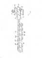
なお、上記実施形態においては、加熱コイル1の両コイル部2、3を外部に略露出する状態で設けたが、例えば図4に示すように、両コイル部2、3を絶縁ケースとしての筒状ケース8内に嵌装状態とすることもできる。すなわち、例えば塩ビパイプ等の絶縁性の筒状ケース8内に、図では模式的に示す往路側コイル部2と復路側コイル部3を嵌挿し、筒状ケース8の上下の開口端に両コイル部2、3を所定位置に保持し得る蓋体9、10を取り付ける。
In the above embodiment, the two
この時、下部の蓋体10に、両コイル部2、3の最下端の巻回部2a、3aの孔内に嵌入する突起10aを設けたり、上部の蓋体9に両コイル部2、3の上端部が挿通する孔9aを設け、両コイル部2、3の筒状ケース8に対する位置決めを行ったり、筒状ケース8内の所定位置にリング状等の突起11を設けて、両コイル部2、3の筒状ケース8内における移動等を防止する。
At this time, the lower lid 10 is provided with a
このように構成しても、ボルトの孔13内面を均一かつ効率的に誘導加熱できる等、上記実施形態の加熱コイル1と同様の作用効果が得られる他に、加熱コイル1の外形寸法d1が筒状ケース8によって一定となるため、例えばボルトの孔13の内径d2に対する両コイル部2、3の外形寸法d1を高精度に設定することができて、孔13内面を一層均一に誘導加熱できる。また、両コイル部2、3が筒状ケース8で完全に絶縁状態となるため、誘導加熱時の両コイル部2、3と孔13内面の接触による電気的な短絡がなくなり、短絡による孔13内面の損傷が確実に防止されたり、加熱コイル1の孔13へのセット作業が簡単となり、ナット緩め作業の能率の一層の向上が図れることになる。
Even if comprised in this way, the outer dimension d1 of the heating coil 1 can be obtained in addition to the same effects as the heating coil 1 of the above-described embodiment, such that the inner surface of the bolt hole 13 can be uniformly and efficiently induction heated. Since it becomes constant by the cylindrical case 8, for example, the outer dimension d1 of both the
ところでこの実施形態の場合、筒状ケース8の外形寸法d1を、ボルトの孔13の内径d2に応じて複数種類準備することにより、各種のボルトに適用することができる。また、筒状ケース8の外形寸法d1は、孔13の内径d2より僅かに小さく設定することが好ましいが、略同一に設定すれば、両コイル部2、3の外周面と孔13内面とを全周全域において、間隔を一層均一に設定できることになる。また、この実施形態において、筒状ケース8内に絶縁性の樹脂を充填して固化させるようにして、両コイル部2、3の位置を一層安定させたり、両コイル部2、3の巻回部2a、3a間の短絡防止を確実に図るようにしても良い。
By the way, in the case of this embodiment, it can apply to various volt | bolts by preparing the external dimension d1 of the cylindrical case 8 according to the internal diameter d2 of the hole 13 of a volt | bolt. The outer dimension d1 of the cylindrical case 8 is preferably set to be slightly smaller than the inner diameter d2 of the hole 13, but if it is set to be substantially the same, the outer peripheral surface of both the
なお、上記各実施形態における加熱コイル1の両コイル部2、3の形状、巻回数、絶縁処理方法、両コイル部2、3とコア4との配置構造や保持構造等は一例であって、例えばボルトの孔の内径や深さ、ボルトの材質等に応じ、本発明に係わる各発明の要旨を逸脱しない範囲において適宜に変更することができる。
In addition, the shape of both the
本発明は、金属製ボルトの孔を加熱してボルトを熱膨張させてナットを緩める場合に限らず、金属部材の孔内面を加熱して例えば焼き入れ、焼き鈍し等の適宜の加熱処理をする場合にも適用できる。 The present invention is not limited to heating the hole of a metal bolt to thermally expand the bolt and loosening the nut, but heating the inner surface of the hole of the metal member to perform appropriate heat treatment such as quenching and annealing. It can also be applied to.
1・・・高周波誘導加熱コイル、2・・・往路側コイル部、2a・・・巻回部、2b・・・連結部、3・・・復路側コイル部、3a・・・巻回部、3b・・・連結部、4・・・コア、5・・・端子板、5a・・・装着用凹部、6・・・連結部、7・・・ホースコネクタ、8・・・筒状ケース、9・・・蓋体、9a・・・孔、10・・・蓋体、10a・・・突起、11・・・突起、12・・・絶縁処理、13・・・孔。 DESCRIPTION OF SYMBOLS 1 ... High frequency induction heating coil, 2 ... Outward side coil part, 2a ... Winding part, 2b ... Connection part, 3 ... Return path side coil part, 3a ... Winding part, 3b: connecting portion, 4 ... core, 5 ... terminal plate, 5a ... mounting recess, 6 ... connecting portion, 7 ... hose connector, 8 ... cylindrical case, 9 ... lid, 9a ... hole, 10 ... lid, 10a ... projection, 11 ... projection, 12 ... insulation treatment, 13 ... hole.
Claims (3)
The outward coil portion and the return coil portion are fitted in an insulating case having an outer shape corresponding to the inner surface shape of the hole, with movement prevented by a protrusion provided in the case. The high frequency induction heating coil according to claim 1 or 2.
Priority Applications (1)
| Application Number | Priority Date | Filing Date | Title |
|---|---|---|---|
| JP2003411117A JP4187635B2 (en) | 2003-12-10 | 2003-12-10 | High frequency induction heating coil |
Applications Claiming Priority (1)
| Application Number | Priority Date | Filing Date | Title |
|---|---|---|---|
| JP2003411117A JP4187635B2 (en) | 2003-12-10 | 2003-12-10 | High frequency induction heating coil |
Publications (2)
| Publication Number | Publication Date |
|---|---|
| JP2005174671A JP2005174671A (en) | 2005-06-30 |
| JP4187635B2 true JP4187635B2 (en) | 2008-11-26 |
Family
ID=34731953
Family Applications (1)
| Application Number | Title | Priority Date | Filing Date |
|---|---|---|---|
| JP2003411117A Expired - Fee Related JP4187635B2 (en) | 2003-12-10 | 2003-12-10 | High frequency induction heating coil |
Country Status (1)
| Country | Link |
|---|---|
| JP (1) | JP4187635B2 (en) |
Families Citing this family (3)
| Publication number | Priority date | Publication date | Assignee | Title |
|---|---|---|---|---|
| JP5694001B2 (en) * | 2011-02-28 | 2015-04-01 | 本田技研工業株式会社 | Induction hardening coil and quenching method using the same |
| JP7446188B2 (en) * | 2020-09-17 | 2024-03-08 | 大阪瓦斯株式会社 | heating device |
| DE102021210454A1 (en) | 2021-09-21 | 2023-03-23 | Thyssenkrupp Ag | Inductor for inductive hardening of metallic materials and manufacturing method for an inductor |
-
2003
- 2003-12-10 JP JP2003411117A patent/JP4187635B2/en not_active Expired - Fee Related
Also Published As
| Publication number | Publication date |
|---|---|
| JP2005174671A (en) | 2005-06-30 |
Similar Documents
| Publication | Publication Date | Title |
|---|---|---|
| JP7362061B2 (en) | Induction heating method and induction heating device | |
| CN104067021B (en) | Spring spool and spring pin | |
| EP0811304B1 (en) | Apparatus and method for inductively heating a workpiece | |
| JP3621685B2 (en) | Inner surface induction heating coil | |
| US5553729A (en) | Induction heating roller apparatus | |
| JP4187635B2 (en) | High frequency induction heating coil | |
| JP2007063642A (en) | Residual stress improvement method and high frequency induction heating coil | |
| JP2011129292A (en) | Induction heating coil | |
| JP2008118731A (en) | Stator coil and core heating apparatus and heating method | |
| JP2019009097A (en) | Induction heating coil | |
| CN215882640U (en) | Electromagnetic induction heating clamp | |
| JP6969714B2 (en) | Induction heating coil | |
| JP7299582B2 (en) | induction heating coil | |
| JPH11329702A (en) | Coil device for induction heating | |
| JP7057505B2 (en) | Repair device | |
| JP5131641B2 (en) | Electromagnetic induction heating device | |
| JP4232963B2 (en) | High frequency induction heating equipment for metal pipes | |
| JPH0355790A (en) | High-frequency heating method and its device | |
| JP7457970B2 (en) | Induction heating coil and induction heating device | |
| GB2311197A (en) | Induction heating | |
| KR102141875B1 (en) | Induction heater for vehicle | |
| JP2019129192A (en) | Output transformer for induction heating | |
| JP2513250Y2 (en) | High frequency heating torch for heating bolts | |
| JPH11291128A (en) | Shaft hole induction heating method of cylindrical work and device therefor | |
| JP2020013635A (en) | Induction heating apparatus |
Legal Events
| Date | Code | Title | Description |
|---|---|---|---|
| A621 | Written request for application examination |
Free format text: JAPANESE INTERMEDIATE CODE: A621 Effective date: 20061205 |
|
| A977 | Report on retrieval |
Free format text: JAPANESE INTERMEDIATE CODE: A971007 Effective date: 20080514 |
|
| A131 | Notification of reasons for refusal |
Free format text: JAPANESE INTERMEDIATE CODE: A131 Effective date: 20080519 |
|
| A521 | Request for written amendment filed |
Free format text: JAPANESE INTERMEDIATE CODE: A523 Effective date: 20080604 |
|
| TRDD | Decision of grant or rejection written | ||
| A01 | Written decision to grant a patent or to grant a registration (utility model) |
Free format text: JAPANESE INTERMEDIATE CODE: A01 Effective date: 20080904 |
|
| A01 | Written decision to grant a patent or to grant a registration (utility model) |
Free format text: JAPANESE INTERMEDIATE CODE: A01 |
|
| A61 | First payment of annual fees (during grant procedure) |
Free format text: JAPANESE INTERMEDIATE CODE: A61 Effective date: 20080909 |
|
| R150 | Certificate of patent or registration of utility model |
Free format text: JAPANESE INTERMEDIATE CODE: R150 Ref document number: 4187635 Country of ref document: JP Free format text: JAPANESE INTERMEDIATE CODE: R150 |
|
| FPAY | Renewal fee payment (event date is renewal date of database) |
Free format text: PAYMENT UNTIL: 20110919 Year of fee payment: 3 |
|
| FPAY | Renewal fee payment (event date is renewal date of database) |
Free format text: PAYMENT UNTIL: 20110919 Year of fee payment: 3 |
|
| FPAY | Renewal fee payment (event date is renewal date of database) |
Free format text: PAYMENT UNTIL: 20120919 Year of fee payment: 4 |
|
| R250 | Receipt of annual fees |
Free format text: JAPANESE INTERMEDIATE CODE: R250 |
|
| FPAY | Renewal fee payment (event date is renewal date of database) |
Free format text: PAYMENT UNTIL: 20120919 Year of fee payment: 4 |
|
| FPAY | Renewal fee payment (event date is renewal date of database) |
Free format text: PAYMENT UNTIL: 20130919 Year of fee payment: 5 |
|
| R250 | Receipt of annual fees |
Free format text: JAPANESE INTERMEDIATE CODE: R250 |
|
| R250 | Receipt of annual fees |
Free format text: JAPANESE INTERMEDIATE CODE: R250 |
|
| R250 | Receipt of annual fees |
Free format text: JAPANESE INTERMEDIATE CODE: R250 |
|
| R250 | Receipt of annual fees |
Free format text: JAPANESE INTERMEDIATE CODE: R250 |
|
| R250 | Receipt of annual fees |
Free format text: JAPANESE INTERMEDIATE CODE: R250 |
|
| R250 | Receipt of annual fees |
Free format text: JAPANESE INTERMEDIATE CODE: R250 |
|
| R250 | Receipt of annual fees |
Free format text: JAPANESE INTERMEDIATE CODE: R250 |
|
| R250 | Receipt of annual fees |
Free format text: JAPANESE INTERMEDIATE CODE: R250 |
|
| R250 | Receipt of annual fees |
Free format text: JAPANESE INTERMEDIATE CODE: R250 |
|
| R250 | Receipt of annual fees |
Free format text: JAPANESE INTERMEDIATE CODE: R250 |
|
| R250 | Receipt of annual fees |
Free format text: JAPANESE INTERMEDIATE CODE: R250 |
|
| LAPS | Cancellation because of no payment of annual fees |