JP4184637B2 - Game machine - Google Patents
Game machine Download PDFInfo
- Publication number
- JP4184637B2 JP4184637B2 JP2001263294A JP2001263294A JP4184637B2 JP 4184637 B2 JP4184637 B2 JP 4184637B2 JP 2001263294 A JP2001263294 A JP 2001263294A JP 2001263294 A JP2001263294 A JP 2001263294A JP 4184637 B2 JP4184637 B2 JP 4184637B2
- Authority
- JP
- Japan
- Prior art keywords
- symbol
- variable display
- game
- virtual
- display
- Prior art date
- Legal status (The legal status is an assumption and is not a legal conclusion. Google has not performed a legal analysis and makes no representation as to the accuracy of the status listed.)
- Expired - Fee Related
Links
Images


Landscapes
- Pinball Game Machines (AREA)
- Display Devices Of Pinball Game Machines (AREA)
Description
【0001】
【発明の属する技術分野】
本発明は、表示装置に複数の識別情報を変動表示する変動表示ゲームを行い、この変動表示ゲームの結果態様に関連して特定の遊技価値を付与可能な遊技機に関する。
【0002】
【従来の技術】
遊技領域に発射した遊技球の入賞等に従って、液晶表示器等からなる変動表示装置に複数の識別情報(図柄)を変動表示する変動表示ゲームを行い、その表示結果が特定の態様となったことに関連して、特典遊技を発生する等の特定の遊技価値を付与するようにした遊技機(パチンコ遊技機)が知られている。
【0003】
このような遊技機の変動表示ゲームでは、識別情報をスクロール表示(例えば、縦スクロールなど)させて変動表示を行うものが広く採用されており、この他、所定の表示領域で識別情報を回転させながら次々と図柄を変えて変動表示を行うものも採用されている。
【0004】
上記変動表示の多くは、2次元(2D)描画処理により行われており、多層のスプライト表示面を利用し、各スプライト面を重ね合わせて一つの識別情報を表示するものが知られている。
【0005】
また、近年では表示制御装置に用いるマイクロプロセッサの処理能力が向上してきたため、3次元(3D)描画処理を採用して図柄や背景等を立体的に表示することが容易になってきており、立体的な変動表示を行うことで、変動表示ゲームに新鮮味を加えることが可能となった。
【0006】
【発明が解決しようとする課題】
ところで、3D描画処理によって変動表示ゲームを行う場合、識別情報をテクスチャデータとして格納しておき、変動表示の際に移動または回転する装飾情報に識別情報をテクスチャリング処理によって順次貼り付けて、変動表示を行うのが一般的ではあり、装飾情報の動きや変化については、従来の2D描画処理に比して飛躍的に向上する。
【0007】
しかしながら、テクスチャとして貼り付けられる識別情報について見ると、スクロールや回転する装飾情報に貼り付けられるだけであるため、従来の2Dの描画処理と大差がなく、識別情報に対する興趣を向上させることが難しいという問題があった。
【0008】
そこで本発明は、上記問題点に鑑みてなされたもので、3次元描画処理を用いた変動表示ゲームにおいて、識別情報に対する興趣を向上させることを目的とする。
【0009】
【課題を解決するための手段】
第1の発明は、可変表示装置の複数の変動表示領域に複数種類の識別情報を変動表示する変動表示ゲームの制御を行う表示制御手段を備え、前記変動表示ゲームの結果態様に関連して特定の遊技価値を付与可能な遊技機において、前記表示制御手段は、複数の仮想平面からなる直方体のモデル空間を仮想3次元空間に設定するモデル空間設定手段と、前記識別情報の一部を構成する図柄構成要素を前記仮想平面に沿うように前記モデル空間に複数配置する図柄構成要素配置手段と、前記図柄構成要素が複数配置された前記モデル空間を回転させるモデル空間回転手段と、前記仮想3次元空間内に予め設定した視点から見た複数の図柄構成要素を前記可変表示装置へ描画する描画手段と、を備え、前記複数の図柄構成要素は、同一形状の3次元オブジェクトからなり、前記図柄構成要素配置手段は、前記モデル空間の回転に応じて前記視点と各仮想平面とが正対したときに、当該視点から見た複数の図柄構成要素の重なり度合いに応じて一の識別情報が形成表示されるように、複数の図柄構成要素を複数の仮想平面に分散して配置する。
【0013】
また、第2の発明は、前記第1の発明において、前記図柄構成要素配置手段は、隣り合う仮想平面でそれぞれ形成表示される識別情報同士が重なる共通部分がある場合には、一の図柄構成要素が前記隣り合う仮想平面のそれぞれで識別情報の一部を構成するように、該隣り合う仮想平面の接続位置に図柄構成要素を配置する。
【0018】
また、第3の発明は、前記第1または第2の発明において、前記表示制御手段は、図柄構成要素同士の重なり度合いによって前記識別情報が形成表示されたことを報知する。
【0019】
【発明の効果】
第1の発明は、可変表示装置の複数の変動表示領域に複数種類の識別情報を変動表示する変動表示ゲームの制御を行う表示制御手段を備え、前記変動表示ゲームの結果態様に関連して特定の遊技価値を付与可能な遊技機において、前記表示制御手段は、複数の仮想平面からなる直方体のモデル空間を仮想3次元空間に設定するモデル空間設定手段と、前記識別情報の一部を構成する図柄構成要素を前記仮想平面に沿うように前記モデル空間に複数配置する図柄構成要素配置手段と、前記図柄構成要素が複数配置された前記モデル空間を回転させるモデル空間回転手段と、前記仮想3次元空間内に予め設定した視点から見た複数の図柄構成要素を前記可変表示装置へ描画する描画手段と、を備え、前記複数の図柄構成要素は、同一形状の3次元オブジェクトからなり、前記図柄構成要素配置手段は、前記モデル空間の回転に応じて前記視点と各仮想平面とが正対したときに、当該視点から見た複数の図柄構成要素の重なり度合いに応じて一の識別情報が形成表示されるように、複数の図柄構成要素を複数の仮想平面に分散して配置することにより、モデル空間の回転によって視点から見た図柄構成要素同士の重なり具合が変化するため、視点と仮想平面とが正対する状態のときにのみ識別情報が形勢表示される一方、その他の状態では意味を持たない図形に変化することで変動表示が立体的に行われ、図柄の立体的な変化によって変動表示ゲームの識別情報に対する興趣を向上させることができる。
【0022】
また、第2の発明は、前記図柄構成要素配置手段は、隣り合う仮想平面でそれぞれ形成表示される識別情報同士が重なる共通部分がある場合には、一の図柄構成要素が前記隣り合う仮想平面のそれぞれで識別情報の一部を構成するように、該隣り合う仮想平面の接続位置に図柄構成要素を配置するので、隣り合う仮想平面で共通の図柄構成要素を持つことで、2面が変動表示の過程で表示されるときに、興趣溢れる図柄形状の表示を行うことができる。
【0027】
また、第3の発明は、前記表示制御手段は、前記複数の仮想平面に配置された複数の図柄構成要素の重なり度合いによって前記識別情報が形成表示されたことを報知する報知手段を備えたので、遊技者は識別情報を正確に認識でき、また、識別情報以外の図形が表示されていた場合に誤認識するのを防止できる。
【0028】
【発明の実施の形態】
以下、添付図面に基づいて、本発明の実施の形態について説明する。
【0029】
図1は遊技機(パチンコ遊技機)の遊技盤1の正面図である。
【0030】
遊技盤1の表面には、ガイドレール2で囲われた遊技領域3のほぼ中央に変動表示装置(可変表示装置、特別図柄表示装置)4が配置され、遊技領域3の下方に大入賞口としての特別変動入賞装置5が配設される。
【0031】
変動表示装置(可変表示装置)4は、例えばLCD(液晶表示器)、CRT(ブラウン管)等で表示画面部分が構成され、複数の変動表示領域に複数の識別情報(図柄)を変動表示する変動表示ゲーム等、遊技の進行に基づく画像が表示される。
【0032】
特別変動入賞装置5は、大入賞口ソレノイド6(図2参照)への通電により、球を受け入れない閉状態(遊技者に不利な状態)から球を受け入れやすい開状態(遊技者に有利な状態)に変換される。
【0033】
特別変動入賞装置5の直ぐ上方には、普通変動入賞装置(普通電動役物)8を有する始動口7が、その左右の所定の位置には、普通図柄始動ゲート20が配設される。
【0034】
普通変動入賞装置8は、普通電動役物ソレノイド10(図2参照)への通電により、始動口7への入口を拡開するように変換される。
【0035】
遊技領域3の各所には、N個(図1には4個のみ示す)の一般入賞口11が設けられる。遊技領域3の最下端には、アウト口12が設けられる。
【0036】
図示しない打球発射装置から遊技領域3に向けて遊技球(パチンコ球)が打ち出されることにより遊技が行われ、打ち出された遊技球は、遊技領域3内の各所に配置された風車等の転動誘導部材13により転動方向を変えられながら遊技領域3表面を流下し、始動口7、一般入賞口11、特別変動入賞装置5に入賞するか、アウト口12から排出される。
【0037】
始動口7への入賞は、特別図柄始動センサ14(図2参照)により検出される。特別変動入賞装置5への入賞は、カウントセンサ15、継続センサ16(図2参照)により検出される。N個の一般入賞口11への入賞は、各一般入賞口11毎に備えられたN個の入賞センサ17A〜17N(図2参照)により検出される。また、普通図柄始動ゲート20への遊技球の通過は、普通図柄始動センサ21(図2参照)により検出される。
【0038】
始動口7への遊技球の入賞は、特別図柄始動記憶として、例えば最大4回分を限度として記憶され、変動表示装置4の下部に、その特別図柄始動記憶の数を表示する特別図柄記憶表示器18が設けられる。
【0039】
普通図柄始動ゲート20への遊技球の通過は、普通図柄始動記憶として、例えば最大4回分を限度として記憶され、特別変動入賞装置5の右側にその普通図柄始動記憶の数を表示する普通図柄記憶表示器22が、特別変動入賞装置5の左側にLED等からなる普通図柄表示器23が配設される。
【0040】
始動口7、一般入賞口11、特別変動入賞装置5に遊技球が入賞すると、入賞した入賞装置の種類に応じた数の賞球が図示しない払出ユニット(排出装置)から排出され、図示しない供給皿(遊技者に対して賞球または貸球が払い出される皿)に供給される。
【0041】
遊技機の要所には、装飾用ランプ、LED等の装飾発光装置が備えられる。また、遊技機には、音出力装置(スピーカ)が備えられる。
【0042】
図2は、遊技制御装置100を中心とする制御系を示すブロック構成図である。
【0043】
遊技制御装置100は、遊技を統括的に制御する主制御装置であり、遊技制御を司るCPU、遊技制御のための不変の情報を記憶しているROM、遊技制御時にワークエリアとして利用されるRAMを内蔵した遊技用マイクロコンピュータ101、入力インターフェース102、出力インターフェース103、発振器104等から構成される。
【0044】
遊技用マイクロコンピュータ101は、入力インターフェース102を介しての各種検出装置(特別図柄始動センサ14、一般入賞口センサ17A〜17N、カウントセンサ15、継続センサ16、普通図柄始動センサ21)からの検出信号を受けて、大当たり抽選等、種々の処理を行う。そして、出力インターフェース103を介して、各種制御装置(表示制御装置150、排出制御装置200、装飾制御装置250、音制御装置300)、大入賞口ソレノイド6、普通電動役物ソレノイド10、普通図柄表示器23等に指令信号を送信して、遊技を統括的に制御する。
【0045】
排出制御装置200は、遊技制御装置100からの賞球指令信号または図示しないカード球貸ユニットからの貸球要求に基づいて、払出ユニットの動作を制御し、賞球または貸球の排出を行わせる。
【0046】
装飾制御装置250は、遊技制御装置100からの装飾指令信号に基づいて、装飾用ランプ、LED等の装飾発光装置を制御すると共に、特別図柄記憶表示器(特図保留LED)18、普通図柄記憶表示器22の表示を制御する。
【0047】
音制御装置300は、スピーカからの効果音出力を制御する。なお、遊技制御装置100から、各種従属制御装置(表示制御装置150、排出制御装置200、装飾制御装置250、音制御装置300)への通信は、遊技制御装置100から従属制御装置に向かう単方向通信のみが許容されるようになっている。これにより、遊技制御装置100に従属制御装置側から不正な信号が入力されることを防止することができる。
【0048】
表示制御装置150は、2D及び3D画像の表示制御を行うもので、CPU151、VDP(Video Display Processorまたは3D画像描画手段)152、DRAM153、154、インターフェース155、プログラム等を格納したROM156、画像データ(図柄データ、背景画データ、動画キャラクタデータ、テクスチャデータ等)を格納したCGROM157、液晶を駆動するLCDI/F等から構成される。
【0049】
CPU151は、PRGROM156に格納したプログラムを実行し、遊技制御装置100からの信号に基づいて、2Dの画面情報(図柄表示情報、背景画面情報、動画キャラクタ画面情報等)を作成したり、3Dの画像情報(オブジェクト)の座標演算(ジオメトリ演算)等を行い、これらの演算結果をDRAM153に格納する。
【0050】
VDP152(3次元図柄生成手段)は、DRAM153に格納された画像情報に基づいて、2Dまたは3Dの画像の描画(レンダリング)を行ってフレームバッファとしてのDRAM154に格納する。そして、DRAM154の画像を所定のタイミング(垂直同期、水平同期)でLCDI/F158へ送出して、液晶で構成された変動表示装置4に出力する。
【0051】
VDP152が行う描画処理は、2Dと3Dの点描画、線描画、トライアングル描画、ポリゴン描画を行い、さらに3D画像では、テクスチャマッピング(テクスチャリング)、ライティング処理、アルファブレンディング、シェーディング処理(グローシェーディングなど)、陰面消去(Zバッファ処理など)を行って、CPU151が設定した3DオブジェクトをフレームバッファとしてのDRAM154へ描画(レンダリング)する。なお、フレームバッファは、2Dのフレームバッファと3Dのフレームバッファをそれぞれ設定しておき、2Dの画像を3Dの画像に重ね合わせて(オーバーレイ)出力することも可能である。
【0052】
なお、VDP152と変動表示装置4の間のインターフェース158は、変動表示装置の種類に応じて適宜選択すればよく、ここでは変動表示装置4に液晶を用いたが、CRT、ELあるいはプラズマなどのディスプレイを採用する場合には、これらのディスプレイデバイスに対応するインターフェース158を用いればよい。
【0053】
また、CGROM157には、変動表示ゲームに用いる識別情報としての各図柄、背景、キャラクタ等の2Dデータ及び3Dオブジェクトデータ、テクスチャデータが格納されている。
【0054】
インターフェース155の手前には、信号伝達方向規制手段であるバッファ回路160が設けられ、遊技制御装置100から表示制御装置150への信号入力のみが許容され、表示制御装置150から遊技制御装置100への信号出力を禁止している。
【0055】
次に、CPU151及びVDP152を主体にして行われる3D描画処理の一例について、図3、図4のフローチャートを参照しながら説明する。
【0056】
まず、図3のフローチャートは、CPU151で実行されるもので、遊技制御装置100からの信号による受信割込処理を示す。
【0057】
図3のステップS111では、遊技制御装置100からの信号を読み込むとともに、受信した信号を解析する。
【0058】
そして、ステップS112では、受信したコマンドに対応する変動表示のパターンを、図示しないテーブルなどから検索し、変動表示ゲームのパターンをセットする。
【0059】
次に、図4は、CPU151及びVDP152を主体にして行われる3D描画処理を示す。
【0060】
ステップS101では、上記ステップS112で決定した変動表示パターンを読み込んで、表示する内容(リーチの種類など)を解析し、3D表示を行うシーン及び3Dオブジェクトを決定する。
【0061】
ステップS102では、予め設定した仮想3次元空間(ワールド空間)内に、選択した3Dオブジェクトを配置する。これは、各3Dオブジェクト毎に設定されたモデル空間をワールド空間に変換するものであり、3Dオブジェクトの回転やスケーリング、位置、サイズなどの変換が含まれる。
【0062】
次に、ステップS103では、上記ステップS101のシーンに応じたワールド空間内のカメラ(視点=ビュー)の位置、方向から、ステップS102で求めたワールド空間を、カメラを原点とするカメラ空間に変換する。
【0063】
ステップS104の射影トランスフォームでは、ビュートランスフォームで求めたカメラ空間を、カメラの視野(視野角)に対応する立体空間に変換する。これにより、視野内の3Dオブジェクトを抽出するとともに、カメラに近い3Dオブジェクトは大きく拡大され、カメラから遠い3Dオブジェクトは縮小される。
【0064】
そして、ステップS105のクリッピングでは、上記カメラの視野に対応した立体空間内の3Dオブジェクト(ポリゴンデータ)を、変動表示装置4のスクリーン座標(表示領域)に対応する立方体空間にクリッピング(変換)する(描画領域変更手段)。
【0065】
上記ステップS102〜S105の処理が、いわゆるジオメトリ演算であり、ここでは、CPU151が処理を行う例を示し、ジオメトリ演算以降のラスタライズを、VDP152が行う例を示している。
【0066】
次に、ステップS106では、上記ステップS105でクリッピングされた立方体内の各ポリゴンデータについて、仮想3次元空間に設定された光源に基づいてライティング処理を行う。このライティングの一例としては、陰影やポリゴンの素材に応じた反射等を演算する。
【0067】
そして、ステップS107では、各ポリゴンの表面に所定のテクスチャを貼り付けるテクスチャマッピングを行って、3Dオブジェクトの外観を決定する。このテクスチャマッピングでは、単純なテクスチャの貼り付けだけではなく、ライトマッピングや環境マッピング、バンプマッピングなどのテクスチャに対する操作も含まれる。
【0068】
次に、ステップS108の深度バッファ処理では、テクスチャマッピングを終了した各ポリゴン上のピクセル毎に深度(奥行)情報を決定しておく。そして、全てのポリゴンのピクセル毎に深度情報を調べ、深度バッファに記憶された深度よりも、カメラに近い場合にそのピクセルを表示するとともに、深度バッファの深度情報を更新する。全てのポリゴンについて、この処理を行うことにより、完全にレンダリングされた3Dの描画データが完成する(描画手段)。
【0069】
そして、この描画データを、DRAM154上に予め設定した変動表示装置4の表示領域へ書き込むことで、1フレーム分の3D画像が生成される。なお、VDP152では、生成した3D画像を2D画像とオーバーレイしたり、生成した3D画像を複数のレイヤに描画して合成することもできる(描画手段)。
【0070】
このように、上記ステップS101〜S9所定の周期で繰り返し実行することにより、遊技制御装置100の指令に応じた3D画像の表示を行うことが可能となる。
【0071】
なお、上記図3、図4の表示制御は、CPU151やVDP152のアーキテクチャ等に応じて適宜選択されるものであり、例えば、図4のステップS102〜S105をCPU151で行う一例を示したが、VDP152がステップS102以降を実行することもでき、また、上記ステップS102以降を、VDP152のハードウェアで実行することも可能である。
【0072】
次に、遊技の概要について、図5の流れ図にしたがって説明する。
【0073】
まず、遊技開始当初(あるいは遊技開始前)の時点では、客待ち状態となっており、客待ち画面の表示を指令する信号が遊技制御装置100から表示制御装置150に送信され、変動表示装置4の画面には客待ち画面(動画または静止画)が表示される。
【0074】
そして、遊技領域3に打ち出された遊技球が始動口7に入賞すると、その入賞に基づき、遊技制御装置100によって所定の乱数が抽出され、変動表示ゲームの大当たりの抽選が行われると共に、遊技制御装置100から表示制御装置150に変動表示を指令する信号が送信され、変動表示装置4の画面の左、右、中の変動表示領域に複数の図柄の変動表示が開始される。
【0075】
この変動表示の開始後、所定時間経過すると、変動表示は例えば左、右、中の順に仮停止(例えば、停止位置にて図柄を微少に変動させること等)されていくが、この過程でリーチ状態(例えば、左の図柄と右の図柄が大当たりの組合せを発生する可能性のある組合せ)が発生すると、所定のリーチ遊技が行われる。このリーチ遊技では、例えば中の図柄の変動表示を極低速で行ったり、高速変動したり、変動表示を逆転したりする。また、リーチ遊技に合わせた背景表示、キャラクタ表示が行われる。
【0076】
なお、仮停止状態とは遊技者が図柄を略停止状態として認識可能な状態であり、最終停止態様が確定しない状態であり、停止状態とは、この仮停止状態と図柄が停止した状態を含む状態である。なお、仮停止状態の具体例としては、停止位置での微少変動の他に、図柄を拡大縮小表示したり、図柄の色を変化させたり、図柄の形状を変化させる等の態様がある。
【0077】
そして、大当たり抽選の結果が大当たりであれば、最終的に左、右、中の図柄が所定の大当たりの組合せで停止され、大当たり(大当たり遊技)が発生する。
【0078】
この、大当たり遊技が発生すると、特別変動入賞装置5が所定期間にわたって開かれる特別遊技が行われる。この特別遊技は、特別変動入賞装置5への遊技球の所定数(例えば10個)の入賞または所定時間の経過(例えば30秒)を1単位(1ラウンド)として実行され、特別変動入賞装置5内の継続入賞口への入賞(継続センサ16による入賞球の検出)を条件に、規定ラウンド(例えば16ラウンド)繰り返される。また、大当たり遊技が発生すると、大当たりのファンファーレ表示、ラウンド数表示、大当たりの演出表示等、遊技制御装置100から表示制御装置150に大当たり遊技の表示を指令する信号が送信され、変動表示装置4の画面に大当たり遊技の表示が行われる。
【0079】
この場合、大当たりが特定の大当たりであれば、大当たり遊技後に特定遊技状態が発生され、次回の大当たりの発生確率を高確率にしたり、後述するように遊技球の始動口7への入賞に基づく変動表示装置4の変動表示ゲームの変動表示時間の短縮等が行われる。
【0080】
前記変動表示ゲーム中あるいは大当たり遊技中に遊技球が始動口7に入賞したとき(特別図柄始動記憶の発生時)には、変動表示ゲームが終了した後(ハズレのとき)にあるいは大当たり遊技が終了した後に、その特別図柄始動記憶に基づき、新たな変動表示ゲームが繰り返される。また、変動表示ゲームが終了したとき(ハズレのとき)、あるいは大当たり遊技が終了したときに、特別図柄始動記憶がないときは、客待ち状態に戻される。
【0081】
なお、普通図柄始動ゲート20を遊技球が通過すると、その通過または普通図柄始動記憶に基づき、普通図柄に関する乱数が抽出され、乱数が当たりであれば、普通図柄表示器23に当たり表示が行われて、始動口7の普通変動入賞装置8が所定時間にわたって拡開され、始動口7への入賞が容易にされる。
【0082】
次に、図6〜図9に、変動表示ゲームの一例について説明する。
【0083】
まず、図6は、変動表示ゲームで使用する識別情報としての図柄40を、3次元モデル空間内(仮想3次元空間内)に配置した概念図を示す。
【0084】
まず、図柄40は、任意の多面体としての直方体のモデル空間50の4つの仮想平面50a、50b、50c、50dに沿った所定の位置に、視点70とそれぞれの面が正対したとき、7つのセグメント(図柄構成要素=3Dオブジェクト)で図柄を構成するように図柄構成要素S1〜S20の空間座標を設定しておき、これら図柄構成要素S1〜S20を選択的に描画またはテクスチャを貼ることにより、数字や文字または図形からなる図柄(識別要素)を構成するものである。なお、ここでは各図柄構成要素S1〜S20を直方体(角柱状)の3次元オブジェクトで構成した場合を示し、これらの図柄構成要素の表示(描画)は、図柄構成要素集合面としての面(仮想平面、以下同様)50a〜50dに沿う所定の位置(座標)で行われる。
【0085】
このモデル空間50は、この空間内を鉛直方向(図中Z軸方向)に貫通した軸51を中心に回転し、予め設定した視点70から見たときの図柄構成要素S1〜S20の描画状態に応じて図柄40が決定される。
【0086】
なお、図6においては、全てのセグメントを描画した場合を示しており、また、座標系は、図中X軸方向が変動表示装置4の表示領域において幅方向に対応し、Y軸方向が同じく表示領域の上下方向に対応し、同様にZ軸方向が変動表示装置4の奥行き方向に対応する。
【0087】
そして、各面50a〜50dの左右で鉛直方向に配置された各図柄構成要素(S1、S2、S6、S7、S11、S12、S16、S17)は、隣り合う面の構成要素を兼ねるように配置されており、つまり、面50aにおいて右側の構成要素S6、S7は、図柄40(モデル空間50)を時計回りに90°回転させたときに、面50bの左側の構成要素になる。
【0088】
次に、図柄(識別要素)の変化の一例について図7を参照しながら説明する。
【0089】
図7の(A1)〜(D2)は、ひとつの図柄を「1」から「2」へ切り替える場合を示しており、図7(A1)は、変動表示装置4に表示される図柄40の状態を示し、(A2)は、モデル空間50における図柄構成要素の描画位置を示しており、以下の(B1)〜(D1)及び(B2)〜(D2)も同様である。
【0090】
図7(A2)では、予め設定した視点70に面50aが正対しており、この状態で奥の面50c側の図柄構成要素S11とS17を描画すると、変動表示装置4上では、図7(A1)のように、意味不明な図柄40が表示される。
【0091】
この状態からモデル空間50を時計回りに90°だけ回転させると、図7の(B2)のように、視点70に面50bが正対し、図7(B1)のように表示領域の上方手前に配置される図柄構成要素S11と、下方の奥に配置される図柄図柄構成S17が一列に揃って、図柄40は立体的な「1」となって、所定の図柄に変化する。このとき、所定の図柄に変化したことを報知するため、図柄構成要素S11、S17のテクスチャを変更したり、変動表示領域の背景色を変更することで、遊技者は現在の図柄40が変動表示ゲームにおいて意味を持つ情報に変化したことを容易に察知することができる。
【0092】
さらに、「1」を示す図柄40(モデル空間50)をさらに回転させ、図7(C2)のように、面50aに沿った図柄構成要素S3〜S5を描画する。
【0093】
そして、図7(B2)の状態から180°回転し、図7(C2)のように面50cが視点70に正対すると、表示領域の図柄40は図7(C1)のように表示されて意味の不明なものに変化する。
【0094】
この状態から、モデル空間50を回転させて、図7(C2)の状態から90°回転すると、図7(D2)のように、視点70に面50dが正対し、横方向の図柄構成要素S3〜S5が手前の面50aに配置され、奥の面50cに縦方向の図柄構成要素S11、S17が配置されて、視点70からみた表示領域には、図7(D1)で示すように、立体的に表示された「2」に変化する。この場合も、図柄構成要素S11、S17のテクスチャを変更したり、変動表示領域の背景色を変更することで、遊技者は現在の図柄40が変動表示ゲームにおいて意味を持つ情報(「2」)に変化したことを容易に察知することができる。
【0095】
なお、図7(C1)、(C2)における図柄構成要素S3〜S5の描画は、徐々に輪郭または面が明確になるようなフェードインを行ってもよい。
【0096】
以上のような図柄40の変動表示によって、鉛直方向の軸51まわりに回転する図柄構成要素の重なり具合に応じて、次々と図柄40を切り替えることができ、図柄自体の変化を楽しむことができ、変動表示ゲーム中の識別情報に対する興趣を向上させることができるのである。
【0097】
このように、文字や数字などを示すひとつの図柄40を、多面体を形成するモデル空間50内に配置される複数の図柄構成要素S1〜S20で構成しておき、モデル空間50を回転させながら所定の数字や文字を表す配列で図柄構成要素S1〜S20を描画または消去することにより、図柄構成要素の重なり具合の変化に応じて変動表示装置4に表示される図柄40は意味のない図形から数字や文字へ繰り返して変化することができ、また、図柄40を構成する図柄構成要素S1〜S20を、複数の面に分散して描画しておくことで、立体感のある図柄40を構成でき、識別情報の変化に対する遊技者の興趣を向上させることができるのである。
【0098】
そして、上記モデル空間50は、図8で示すように、全表示領域に対応する空間へ座標変換処理を行って、表示領域内の所定の位置で変動表示を行う。例えば、3つの図柄40L、40C、40Rで変動表示ゲームを行う場合、背景(図示せず)を含めた空間内へ、各モデル空間50、50’、50”を所定の位置に配置(座標変換)し、それぞれ上述のように回転させながら図柄構成要素の描画を行うことで、所定の視点170から見た3次元画像は、図9のように表示され、3つの変動表示領域において、図柄40L〜40Rが回転スクロールしながら、無意味な図形と数字や文字への変化を繰り返して変動表示ゲームが行われる。
【0099】
所定の視点から表示した場合に識別情報が形成され、他の視点からは識別情報が形になっていないので、新たな図柄表示形態で変動表示に新鮮味を付与することが可能となって、遊技者は変動表示ゲームの図柄の変化に対して新たな興趣を得ることができる。
【0100】
また、仮想平面に沿って図柄が重なり合って図柄を構成する状態から、図柄構成要素が分離して他の図形へ変化する過程を立体的に楽しむことができ、斬新な変動表示を行うことが可能となり、遊技者は、図柄構成要素が重なり合って表示される図柄に対して期待を込めて注視することができ、図柄に対する興趣を向上させることが可能となる。
【0101】
図10は第2の実施形態を示し、前記第1実施形態の直方体のモデル空間50を用い、視点70と正対する面と隣り合い、かつ次に表示される面を常時表示させるとともに、次に表示される面には数字や文字などの図形を描画しておくものである。
【0102】
図10の(A1)〜(D2)は、ひとつの図柄40を、90°回転するごとに「7」から「0」へ順次切り替える場合を示す。
【0103】
図10(A1)は、変動表示装置4に表示される図柄40の状態を示し、(A2)は、モデル空間50における図柄構成要素の描画位置を示し、以下の(B1)〜(D1)及び(B2)〜(D2)も同様である。なお、モデル空間50は上記図6と同様である。
【0104】
図10(A2)では、予め設定した視点70に面50aが正対しており、面50aに沿った図柄構成要素S3、S6、S7が描画されて、図10(A1)で示すように、変動表示装置4の変動表示領域に「7」を表示し、この面50aと隣り合う面50bには、「8」の一部を構成する図柄構成要素S8〜S11が描画されている。
【0105】
図10(A2)の状態からモデル空間50を時計回りに90°だけ回転させると、図10の(B2)のように、視点70に面50bが正対して変動表示領域に表示される一方、「7」を示していた面50aは表示されず、代わって、次に表示される面50cが表示され、この面に沿う図柄構成要素S11、S13〜S17が描画されて「9」を表示している。
【0106】
面50bに描画された「8」は、全てが描画されているわけではなく、右下の図柄構成要素S12が描画されていない。しかし、隣り合う面50cに描画された「9」の構成要素である図柄構成要素S17が、欠落している図柄構成要素S12を補い、図10(B1)のように、図柄40は、一部の図柄構成要素S17が奥行き方向にある立体的な「8」として表示される。
【0107】
なお、図(B1)において、図柄構成要素S13〜S15の端面にテクスチャが貼られてしまうと、「8」の形状に違和感が生じる。描画に不要な面が生じた場合には、その面を透過させるか(テクスチャを貼らない)、あるいは、背景と同一のテクスチャを貼ることによって違和感のない図柄を表示できる。
【0108】
次に、図10(B2)の状態からモデル空間50を時計回りに90°だけ回転させると、図10の(C2)のように視点70に面50cが正対し、図10(C1)で示すように変動表示領域の図柄40には「9」が表示される一方、「8」を示していた面50bは表示されず、代わって、次に表示される面50cが表示され、この面に沿う図柄構成要素S18、S20が描画されて「0」の一部を表示している。
【0109】
さらに、図10(C2)の状態からモデル空間50を時計回りに90°だけ回転させると、図10の(D2)のように視点70に面50aが正対し、面50aには「0」の一部が表示される一方、「9」を示していた面50cは表示されず、代わって、次に表示される面50dが表示され、この面に沿う図柄構成要素S6、S7が描画されて「1」を表示している。
【0110】
面50dに描画された「0」は、全てが描画されているわけではなく、右側の図柄構成要素S1、S2が描画されていない。しかし、隣り合う面50aに描画された「1」の構成要素である図柄構成要素S6、S7が、欠落している図柄構成要素S1、S2を補い、図10(D1)のように、図柄40は、一部の図柄構成要素S6、S7が奥行き方向にある立体的な「0」として図柄40が表示される。
【0111】
このように、右から左へ図柄40が回転スクロール表示を行い、右から現れた図柄40が左側へ消えていく。左側から新たに現れる面には、現在正対している面に描画された図柄40の一部を示す図柄構成要素が含まれるため、2つの面の図柄構成要素によって、図柄40が立体的に表示されるので、図柄40に対する興趣が向上する。
【0112】
例えば、図11に示すように、図柄40aと隣り合う仮想平面に図柄40bが描画され、がい骨のキャラクタ60とともに図柄40を構成することができる。
【0113】
ここでは、ひとつの図柄を複数の図柄構成要素で構成するため、上記のような柱状の図柄構成要素に代わって骨S’を図柄構成要素としている。
【0114】
図において、キャラクタ60及び図柄40は時計回り(上から見て)に回転しており、「7」を示す図柄40aが左側へ徐々に消えていく一方、右側から「8」の図柄40bが現れる。
【0115】
さらに、数字の「7」を示す図柄40aと、数字の「8」を示す図柄40bは、鉛直方向の骨S’を共有して構成されるため、次に表示される図柄に対する期待感を高めることができる。
【0116】
このように、現在表示されている隣りの面には、次の図柄が描画されているため、変動表示が始まるとすぐに次の図柄に関連する表示形態を視認することができ、期待を持って変動表示を注視することができる。つまり、現在表示されている識別図柄の重合状態が解除されたら、すぐに次の図柄が回転に応じて現れるので次の図柄を想像する面白さを味わうことができ、図柄の変化による変動表示ゲームの興趣を向上することができる。
【0117】
また、複数の図柄構成要素により図柄40が立体的に組み立てられているため、図柄40の回転や視点移動による図柄の変化を立体的に楽しむことができ、図柄40(識別情報)に対する興趣を向上させることができるのである。
【0118】
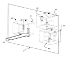
図12、図13は、第3の実施形態を示し、前記第1実施形態の図6に示したモデル空間50のうち、表示領域の奥行き方向にz1だけ離れた2つの仮想平面50a、50cに沿って、それぞれ図柄構成要素S1〜S7及びS11〜S17を所定の位置に設定し、表示する数字、文字や図形に応じてこれら図柄構成要素を選択的に描画するものである。
【0119】
ただし、ひとつの数字などを表示するに当たって、2つの仮想平面50a、50c上の図柄構成要素を必ず用いて表示することで、図柄40を立体的に構成するもので、一方の仮想平面のみに図柄構成要素を描画を行い、2D表示となってしまうのを防ぐため、予め設定したパターンで図柄構成要素の描画が行われる。
【0120】
図12において、視点70の手前側に仮想平面50aが配置され、この奥に仮想平面50bが対向する位置で、かつ、平行に配置される。
【0121】
そして、各仮想平面に沿って選択的に描画される図柄構成要素S1〜S7と、S11〜S17は、視点70から見た位置で重なり合うように設定される。
【0122】
次に、2つの仮想平面50a、50cによる図柄40の立体的な表示について、図13を参照しながら詳述する。
【0123】
図13(A1)〜(D2)は、図柄として「1」〜「4」を描画する場合のパターンの一例を示す。
【0124】
図13(A1)は、変動表示装置4の表示領域に表示される図柄40(「1」)の状態を示し、(A2)は、モデル空間50における図柄構成要素の描画位置を示しており、以下の(B1)〜(D1)及び(B2)〜(D2)も同様である。
【0125】
図13(A2)では、予め設定した視点70に面50a、50cが正対しており、数字の「1」の描画パターンは、視点側の面50aに沿った図柄構成要素S6のみを描画し、奥の面50cに沿った図柄構成要素はS12のみを描画する。
【0126】
これにより、変動表示装置4の表示領域には図13(A1)のように、上半分が手前側、下半分が奥に配置された数字の「1」が立体的に描画される。
【0127】
同様に、数字の「2」を描画する場合では、図13(B2)のように、視点側(手前側)の面50aに沿った図柄構成要素のうちS3〜S4を描画し、奥の面50cに沿った図柄構成要素はS11、S17を描画する。
【0128】
これにより、変動表示装置4の表示領域には図13(B1)のように、水平方向の図柄構成要素S3〜S5が手前側、垂直方向の図柄構成要素S11、S17が奥に配置されて、数字の「2」が立体的に描画される。
【0129】
数字の「3」を描画する場合では、図13(C2)のように、視点側(手前側)の面50aに沿った図柄構成要素のうちS6のみを描画し、奥の面50cに沿った図柄構成要素はS12〜S15を描画する。
【0130】
これにより、変動表示装置4の表示領域には図13(C1)のように、垂直方向の図柄構成要素S6のみが手前側で、その他の図柄構成要素が奥に配置されて、数字の「3」が立体的に描画される。
【0131】
同様に、数字の「4」を描画する場合では、図13(D2)のように、視点側(手前側)の面50aに沿った図柄構成要素のうちS7のみを描画し、奥の面50cに沿った図柄構成要素はS11、S14、S16を描画する。
【0132】
これにより、変動表示装置4の表示領域には図13(D1)のように、垂直方向の図柄構成要素S7のみが手前側で、その他の図柄構成要素が奥に配置されて、数字の「4」が立体的に描画される。
【0133】
以上のように、特定の視点から表示した場合に図柄が形成され、他の視点からは図柄が有意な形になっていないので、新たな図柄表示形態で変動表示の新鮮を演出でき、遊技者は新たな興趣を得ることが可能となる。
【0134】
なお、上記図13に示した各図柄40は、前記実施形態のように回転させても良いし、従来のように縦スクロールや横スクロールに用いることができる。
【0135】
また、手前の図柄構成要素(仮想平面50a側)と奥の図柄構成要素(仮想平面50c側)のスクロールの同期を一時的にずらして変動表示しても良い。
【0136】
これについて説明すると、縦スクロールの場合では、図14に示すように、「2」を図柄40として変動表示する際には、例えば、図14(A2)のように手前の仮想平面50aを視点70の位置にスクロールさせて停止状態にする。このとき、変動表示装置4の表示領域では図14(A1)のように、漢数字の「三」のような図形が表示される。
【0137】
次いで、図14(B2)のように、奥の仮想平面50cを視点70の位置へスクロールさせると、2つの仮想平面に沿った図柄構成要素が重なり合って、図14(B1)のように所定の図柄である「2」が表示される。このとき、所定の図柄が表示されたことを明示するため、図柄構成要素のテクスチャを変更したり、背景色を変更することで、遊技者は図柄の切り替わりを容易に認識できる。
【0138】
この後、図14(C2)のように、仮想平面50aをスクロールさせて表示領域から出すと、表示領域では図14(C1)のように、認識不能な模様(認識不能図柄)となり、この後、奥の仮想平面50cをスクロールさせて表示領域から出すとともに、次の図柄40を構成する手前側または奥の仮想平面のうちの一方を視点70の位置へ移動させる。
【0139】
上記図14(A1)〜(C2)を複数の変動表示領域で繰り返すことにより、図柄構成要素の重なりに応じて図柄40を変化させ、視覚的な楽しみを付与して変動表示ゲームの興趣をさらに向上させることができる。
【0140】
図15、図16は、第4の実施形態を示し、前記第1実施形態の仮想3次元モデル空間内を格子状に区切り、球状の図柄構成要素を多数配置可能にするとともに、選択的に描画することで、図柄40を構成するようにしたものである。
【0141】
図15において、モデル空間50’内には、図柄構成要素を配置するための座標が、X−Y−Z軸方向にそれぞれ格子状に設定されており、図柄構成要素S1〜Snを選択的に描画することで、多種の文字や図形を立体的に表示可能となり、上記実施形態の7セグメントの図柄構成要素に比して、図柄40の種類を拡大することができる。
【0142】
このモデル空間50’の場合も上記実施形態と同様にして、視点70の移動やモデル空間50’の回転によって図柄の変動表示を行うことできる。
【0143】
例えば、図16(A)〜(C)のように、仮想平面50a側に視点70を設定したときに、図柄40が「1」となり、仮想平面50b側に視点70を移動したときには図柄40が「2」となるように、図柄構成要素を描画しておく。
【0144】
そして、(A)のように視点70を仮想平面50aと対向する位置に移動すると、図16(B)で示すように、変動表示装置4の表示領域には「1」の図柄40が表示される。
【0145】
次に、図16(A)で示すように、モデル空間50’の外周に沿って視点70を70’まで移動すると、図(B)、(C)のように、図柄40を「1」から「2」へ滑らかに変化させることができ、図柄40の変化に対する興趣を向上させることができる。
【0146】
なお、図柄40を「2」からさらに変化させるには、モデル空間50’の底面となる仮想平面50fに沿って次の図柄に対応する図柄構成要素を描画しておき、視点70を仮想平面50f側に移動した時点で、「2」の図柄を構成していた図柄構成要素を消去すればよい。
【0147】
また、図柄40を変化させる途中に、装飾情報を挟んでもよく、例えば、図17の(A)〜(C)のように、仮想平面50a側に視点70を設定したときに、図柄40が「1」となり、仮想平面50b側に視点70を移動したときには図柄40が図17(C)のような装飾情報となるように、図柄構成要素を描画しておく。
【0148】
そして、図(A)のように視点70を仮想平面50aと対向する位置に移動すると、図16(B)で示すように、変動表示装置4の表示領域には「1」の図柄40が表示される。
【0149】
次に、図16(A)で示すように、モデル空間50’の外周に沿って視点70を70’まで移動すると、図(B)のように、図柄40を「1」から装飾情報へ滑らかに変化させることができ、図柄40の変化に対する興趣を向上させることができる。
【0150】
さらに、図柄40を装飾情報から「2」へ変化させるには、モデル空間50’の底面となる仮想平面50fと平行するように「2」の図柄に対応する図柄構成要素を描画しておき、視点70を仮想平面50f側に移動した時点で、装飾情報の図柄を構成していた図柄構成要素を消去すればよい。
【0151】
こうして、図柄を変化させている途中に装飾情報を挟み、装飾情報が出たときには、変動表示の態様を予告(例えば、リーチ予告、大当り予告等)と設定しておくことで、遊技者は変動表示される図柄を注視しているときに変動表示の態様可能性を知ることができ、遊技の興趣を更に得やすい。また、重合状態となったときに初めて認識できるので、突然に装飾図柄が形作られることとなり、興趣を与えやすい。
【0152】
なお、上記実施形態において、モデル空間50を直方体としたが、立方体や球体などの任意の空間に図柄構成要素を配置してもよい。
【0153】
また、上記実施形態においては、視点70を固定して立体的な図柄40を表示するものは、視点70を図柄40(モデル空間50)まわりに移動しても変動表示を行うことができる。
【0154】
また、今回開示された実施の形態は全ての点で例示であって制限的なものではないと考えられるべきである。本発明の範囲は上記した説明ではなくて特許請求の範囲によって示され、特許請求の範囲と均等の意味および範囲内での全ての変更が含まれることが意図される。
【図面の簡単な説明】
【図1】パチンコ機の遊技盤を示す正面図である。
【図2】パチンコ機の制御系統を示すブロック図である。
【図3】表示制御装置で行われる受信割込処理の一例を示すフローチャートである。
【図4】表示制御装置で行われる3次元描画処理の一例を示すフローチャートである。
【図5】遊技の流れを示す図である。
【図6】ひとつの図柄を構成する仮想3次元空間の斜視図を示す。
【図7】同じく、図柄が「1」から「2」へ変化するときの仮想3次元空間の斜視図及び表示状態を示し、(A1)は「1」に必要な図柄構成要素を描画したときの表示領域の正面図で、(A2)は、同じく「1」に必要な図柄構成要素を描画したときの仮想3次元空間の斜視図で、(B1)は「1」が表示されたときの正面図で、(B2)は、仮想3次元空間が90°回転して「1」を表示したときの斜視図で、(C1)は「2」に必要な図柄構成要素を描画したときの表示領域の正面図で、(C2)は、同じく「2」に必要な図柄構成要素を描画したときの仮想3次元空間の斜視図で、(D1)は「2」が表示されたときの正面図で、(D2)は、仮想3次元空間が180°回転して「2」を表示したときの斜視図である。
【図8】仮想3次元空間を表示領域内に3つ配置したときの斜視図。
【図9】同じく、仮想3次元空間を表示領域内に3つ配置したときの変動表示装置の正面図。
【図10】第2の実施形態を示し、隣り合う仮想平面間で、図柄の回転を行う場合の仮想3次元空間の斜視図及び表示領域の正面図で、(A1)は「7」が表示されたときの図柄構成要素の正面図で、(A2)は、同じく「7」を表示しているときの2つの仮想平面に描画された図柄構成要素を示す斜視図で、(B1)は図柄が「8」に変化したときの図柄構成要素の正面図で、(B2)は、仮想3次元空間が90°回転して「8」を表示したときの斜視図で、(C1)は図柄が「9」に変化したときの図柄構成要素の正面図で、(C2)は、仮想3次元空間が90°回転して「9」を表示したときの斜視図で、(D1)は図柄が「0」に変化したときの図柄構成要素の正面図で、(C2)は、仮想3次元空間が90°回転して「0」を表示したときの斜視図を示す。
【図11】隣り合う仮想平面間で回転を行う図柄の一例を示す斜視図である。
【図12】第3の実施形態を示し、対向する仮想平面上に描画した図柄構成要素の重なりに応じて図柄の表示を行う場合を示し、仮想3次元空間の斜視図。
【図13】仮想3次元空間の斜視図及び表示領域の正面図で、(A1)は「1」が表示されたときの図柄構成要素の正面図で、(A2)は、同じく「1」を表示しているときの2つの仮想平面に描画された図柄構成要素を示す斜視図で、(B1)は図柄が「2」に変化したときの図柄構成要素の正面図で、(B2)は、仮想3次元空間が「2」を表示したときの斜視図で、(C1)は図柄が「3」に変化したときの図柄構成要素の正面図で、(C2)は、「3」を表示したときの仮想3次元空間の斜視図で、(D1)は図柄が「4」に変化したときの図柄構成要素の正面図で、(C2)は、仮想3次元空間が「0」を表示したときの斜視図を示す。
【図14】対向する仮想平面が順次スクロールする場合の一例を示し、(A1)は「2」を表示する手前側の仮想平面がスクロールしたときの図柄構成要素の正面図で、(A2)は、同じく手前側の仮想平面がスクロールしたときの仮想3次元空間を示す斜視図で、(B1)は奥の仮想平面がスクロールして、図柄構成要素の重なりにより識別情報である「2」を表示したときの正面図、(B2)は、奥の仮想平面がスクロールしてきたときの仮想3次元空間の斜視図で、(C1)は「2」の図柄表示が終了したときの図柄構成要素の正面図で、(C2)は、同じく手前側の仮想平面がスクロールしていったときの仮想3次元空間の斜視図である。
【図15】第4の実施形態を示し、仮想3次元空間内に多数の球状体を格子状に配置して図柄の変動表示を行う場合の斜視図。
【図16】同じく、視点移動による変動表示の一例を示し、(A)は「1」及び「2」を表示するときの視点移動を示す仮想3次元空間の斜視図で、(B)は、「1」を表示したときの表示領域を示す正面図で、(C)は「2」を表示したときの表示領域を示す正面図で、
【図17】同じく、視点移動による変動表示の一例を示し、(A)は「1」及び装飾情報を表示するときの視点移動を示す仮想3次元空間の斜視図で、(B)は、「1」を表示したときの表示領域を示す正面図で、(C)は装飾情報を表示したときの表示領域を示す正面図で、(D)は「2」を表示したときの表示領域を示す正面図である。
【符号の説明】
1 遊技盤
4 変動表示装置
40 図柄(特別図柄、識別情報)
S1〜S20 図柄構成要素
50 モデル空間(仮想3次元空間)
70 視点(カメラ)
100 遊技制御装置
101 遊技用マイコン(遊技制御手段、変動時間制御手段)
150 表示制御装置(変動表示態様記憶手段、表示制御態様選択手段、変動表示制御手段)
152 VDP(3D画像描画手段)[0001]
BACKGROUND OF THE INVENTION
The present invention relates to a gaming machine capable of performing a variable display game in which a plurality of pieces of identification information are displayed in a variable manner on a display device, and giving a specific game value in relation to the result mode of the variable display game.
[0002]
[Prior art]
In accordance with winnings of game balls launched in the game area, a variable display game that displays a plurality of identification information (designs) on a variable display device composed of a liquid crystal display or the like is performed, and the display result is in a specific mode. In relation to the above, there is known a gaming machine (pachinko gaming machine) which is given a specific gaming value such as generating a bonus game.
[0003]
In such a variable display game of a gaming machine, one in which identification information is scrolled (for example, vertically scrolled) to perform variable display is widely adopted. In addition, the identification information is rotated in a predetermined display area. However, the one that changes the design one after another and performs the variable display is also adopted.
[0004]
Many of the above-described variable displays are performed by two-dimensional (2D) drawing processing, and a display using a multi-layer sprite display surface and overlapping each sprite surface to display one identification information is known.
[0005]
Also, in recent years, the processing capability of microprocessors used in display control devices has improved, and it has become easy to display three-dimensional (3D) drawing processing and to display three-dimensional patterns and backgrounds. It is possible to add a fresh taste to the fluctuation display game by performing a dynamic fluctuation display.
[0006]
[Problems to be solved by the invention]
By the way, when a variable display game is played by the 3D drawing process, the identification information is stored as texture data, and the identification information is sequentially pasted to the decoration information that moves or rotates during the variable display by the texturing process. In general, the movement and change of the decoration information is dramatically improved as compared with the conventional 2D drawing process.
[0007]
However, looking at the identification information pasted as a texture, it is only pasted on scrolling and rotating decoration information, so it is not much different from the conventional 2D drawing process, and it is difficult to improve the interest in the identification information There was a problem.
[0008]
Therefore, the present invention has been made in view of the above-described problems, and an object thereof is to improve the interest in identification information in a variable display game using a three-dimensional drawing process.
[0009]
[Means for Solving the Problems]
The first invention provides a plurality of variable display areas of the variable display device.Multiple typesIn a gaming machine that includes display control means for controlling a variable display game for displaying the identification information in a variable manner and is capable of giving a specific game value in relation to the result mode of the variable display game, the display control means includes a plurality of display control means.A rectangular model space consisting of virtual planesVirtual 3DModel space setting means for setting in space, symbol component arrangement means for arranging a plurality of symbol components constituting part of the identification information in the model space along the virtual plane, and a plurality of symbol components A model space rotating means for rotating the arranged model space, and in the virtual three-dimensional space;Viewed from a preset viewpointA plurality of symbol componentsDrawing means for drawing on a variable display device,The plurality of symbol components are composed of three-dimensional objects having the same shape, and the symbol component arrangement unit is configured to start from the viewpoint when the viewpoint and each virtual plane face each other according to the rotation of the model space. In order to form and display one piece of identification information according to the degree of overlap of the plurality of symbol components that have been seen,Multiple design componentsAre distributed over a plurality of virtual planes.
[0013]
The second invention is the first invention, whereinWhen there is a common part in which the identification information formed and displayed in adjacent virtual planes overlap each other, the symbol component arrangement means has a part of the identification information in each of the adjacent virtual planes. The symbol component is arranged at the connection position of the adjacent virtual plane so as to constitute.
[0018]
According to a third aspect, in the first or second aspect, the display control means notifies that the identification information has been formed and displayed according to the degree of overlap between symbol components.
[0019]
【The invention's effect】
The first invention isProvided with display control means for controlling a variable display game that displays a plurality of types of identification information in a plurality of variable display areas of the variable display device, a specific game value can be given in relation to the result mode of the variable display game In such a gaming machine, the display control means includes a model space setting means for setting a model space of a rectangular parallelepiped composed of a plurality of virtual planes in a virtual three-dimensional space, and a symbol component constituting a part of the identification information as the virtual component. A plurality of symbol component arrangement means for arranging in the model space along a plane, a model space rotation means for rotating the model space in which a plurality of the symbol components are arranged, and preset in the virtual three-dimensional space Drawing means for drawing a plurality of symbol components viewed from a viewpoint on the variable display device, wherein the plurality of symbol components are three-dimensional objects having the same shape. When the viewpoint and each virtual plane face each other in accordance with the rotation of the model space, the symbol component arranging means is set to one according to the overlapping degree of the plurality of symbol components viewed from the viewpoint. Distribute and arrange multiple symbol components on multiple virtual planes so that identification information is formed and displayedBySeen from the viewpoint by rotation of the model spaceSince the degree of overlap between symbol components changes,Facing the virtual planeIn stateKnowledgeAnother informationWhile the status is displayed,In other states, the display is changed three-dimensionally by changing to a figure having no meaning, and the interest in the identification information of the change display game can be improved by the three-dimensional change of the design.
[0022]
In addition, the second invention,When there is a common part in which the identification information formed and displayed in adjacent virtual planes overlap each other, the symbol component arrangement means has a part of the identification information in each of the adjacent virtual planes. Since the symbol components are arranged at the connection positions of the adjacent virtual planes so that the two virtual planes are displayed in the process of variable display by having a common symbol component in the adjacent virtual planes. In addition, it is possible to display an interesting symbol shape.
[0027]
Further, in the third aspect of the invention, the display control means includes notifying means for notifying that the identification information is formed and displayed according to the overlapping degree of the plurality of symbol components arranged on the plurality of virtual planes. The player can accurately recognize the identification information, and can prevent erroneous recognition when a graphic other than the identification information is displayed.
[0028]
DETAILED DESCRIPTION OF THE INVENTION
Hereinafter, embodiments of the present invention will be described with reference to the accompanying drawings.
[0029]
FIG. 1 is a front view of a
[0030]
On the surface of the
[0031]
The variable display device (variable display device) 4 includes a display screen portion composed of, for example, an LCD (liquid crystal display), a CRT (CRT), etc., and a variable display that displays a plurality of identification information (symbols) in a plurality of variable display areas. An image based on the progress of the game such as a display game is displayed.
[0032]
The special variable winning
[0033]
Immediately above the special variable winning
[0034]
The normal
[0035]
In each place of the
[0036]
A game is played by launching a game ball (pachinko ball) from a hitting ball launching device (not shown) toward the
[0037]
The winning at the
[0038]
The winning of the game ball to the
[0039]
The passing of the game ball to the normal
[0040]
When a game ball wins the
[0041]
A key point of the gaming machine is provided with a decorative light emitting device such as a decorative lamp or LED. The gaming machine is also provided with a sound output device (speaker).
[0042]
FIG. 2 is a block configuration diagram showing a control system centered on the
[0043]
The
[0044]
The
[0045]
The
[0046]
The decoration control device 250 controls a decoration light emitting device such as a decoration lamp or LED based on a decoration command signal from the
[0047]
The
[0048]
The
[0049]
The
[0050]
The VDP 152 (three-dimensional symbol generation means) draws (renders) a 2D or 3D image based on the image information stored in the
[0051]
The drawing processing performed by the
[0052]
The
[0053]
The
[0054]
In front of the
[0055]
Next, an example of 3D drawing processing performed mainly by the
[0056]
First, the flowchart of FIG. 3 is executed by the
[0057]
In step S111 of FIG. 3, while reading the signal from the
[0058]
In step S112, a variation display pattern corresponding to the received command is searched from a table (not shown), and a variation display game pattern is set.
[0059]
Next, FIG. 4 shows 3D drawing processing performed mainly by the
[0060]
In step S101, the variation display pattern determined in step S112 is read, the contents to be displayed (reach type, etc.) are analyzed, and the scene and 3D object to be displayed in 3D are determined.
[0061]
In step S102, the selected 3D object is placed in a preset virtual three-dimensional space (world space). This is to convert the model space set for each 3D object into the world space, and includes conversion of rotation, scaling, position, size, etc. of the 3D object.
[0062]
Next, in step S103, the world space obtained in step S102 is converted into the camera space with the camera as the origin from the position and direction of the camera (viewpoint = view) in the world space corresponding to the scene in step S101. .
[0063]
In the projection transform in step S104, the camera space obtained by the view transform is converted into a three-dimensional space corresponding to the field of view (viewing angle) of the camera. As a result, the 3D object in the field of view is extracted, the 3D object close to the camera is greatly enlarged, and the 3D object far from the camera is reduced.
[0064]
In the clipping in step S105, the 3D object (polygon data) in the three-dimensional space corresponding to the field of view of the camera is clipped (converted) to the cubic space corresponding to the screen coordinates (display area) of the variable display device 4 ( Drawing area changing means).
[0065]
The processing in steps S102 to S105 is a so-called geometry calculation. Here, an example is shown in which the
[0066]
Next, in step S106, lighting processing is performed on each polygon data clipped in step S105 based on the light source set in the virtual three-dimensional space. As an example of this lighting, a reflection or the like corresponding to a shadow or a polygon material is calculated.
[0067]
In step S107, texture mapping is performed by pasting a predetermined texture on the surface of each polygon to determine the appearance of the 3D object. This texture mapping includes not only simple texture pasting but also operations on the texture such as light mapping, environment mapping, and bump mapping.
[0068]
Next, in the depth buffer processing in step S108, depth (depth) information is determined for each pixel on each polygon for which texture mapping has been completed. Then, the depth information is checked for each pixel of all polygons, and when the pixel is closer to the camera than the depth stored in the depth buffer, the pixel is displayed and the depth information in the depth buffer is updated. By performing this process for all polygons, completely rendered 3D drawing data is completed (drawing means).
[0069]
Then, the drawing data is written in the display area of the
[0070]
As described above, by repeatedly executing the above steps S101 to S9 at a predetermined cycle, it is possible to display a 3D image in accordance with a command from the
[0071]
The display control in FIGS. 3 and 4 is appropriately selected according to the architecture of the
[0072]
Next, an outline of the game will be described according to the flowchart of FIG.
[0073]
First, at the beginning of the game (or before the start of the game), the customer waiting state is entered, and a signal instructing display of the customer waiting screen is transmitted from the
[0074]
Then, when the game ball launched into the
[0075]
When a predetermined time elapses after the start of the variable display, the variable display is temporarily stopped in the order of, for example, left, right, and middle (for example, the pattern is slightly changed at the stop position). When a state (for example, a combination in which the left symbol and the right symbol may generate a jackpot combination) occurs, a predetermined reach game is performed. In this reach game, for example, the variation display of the inside symbol is performed at a very low speed, the variation is performed at a high speed, or the variation display is reversed. In addition, background display and character display in accordance with the reach game are performed.
[0076]
The temporary stop state is a state in which the player can recognize the symbol as a substantially stopped state, and the final stop mode is not determined. The stopped state includes the temporary stop state and the state in which the symbol is stopped. State. As a specific example of the temporary stop state, in addition to the slight fluctuation at the stop position, there are modes such as displaying the symbol in an enlarged scale, changing the color of the symbol, changing the shape of the symbol, and the like.
[0077]
If the result of the jackpot lottery is a jackpot, the left, right, and middle symbols are finally stopped in a predetermined jackpot combination, and a jackpot (jackpot game) is generated.
[0078]
When the jackpot game is generated, a special game is performed in which the special
[0079]
In this case, if the jackpot is a specific jackpot, a specific gaming state is generated after the jackpot game, and the probability of the next jackpot occurrence is increased to a high probability, or fluctuation based on winnings to the
[0080]
When the game ball wins the start opening 7 during the variable display game or the big hit game (when the special symbol start memory is generated), the big hit game ends after the variable display game ends (when it is lost) or After that, a new variation display game is repeated based on the special symbol start memory. Further, when the variable display game is finished (when lost), or when the big hit game is finished, when there is no special symbol start memory, the waiting state is returned to the customer.
[0081]
When the game ball passes through the normal
[0082]
Next, an example of the variable display game will be described with reference to FIGS.
[0083]
First, FIG. 6 shows a conceptual diagram in which a
[0084]
First, the
[0085]
The
[0086]
FIG. 6 shows a case where all segments are drawn. In the coordinate system, the X-axis direction in the drawing corresponds to the width direction in the display area of the
[0087]
And each symbol component (S1, S2, S6, S7, S11, S12, S16, S17) arrange | positioned at the right and left of each
[0088]
Next, an example of a change in the design (identification element) will be described with reference to FIG.
[0089]
7A1 to 7D2 show a case where one symbol is switched from “1” to “2”, and FIG. 7A1 shows the state of the
[0090]
In FIG. 7 (A2), the
[0091]
When the
[0092]
Further, the symbol 40 (model space 50) indicating “1” is further rotated to draw symbol components S3 to S5 along the
[0093]
Then, after rotating 180 ° from the state of FIG. 7 (B2) and the
[0094]
When the
[0095]
Note that the drawing of the symbol components S3 to S5 in FIGS. 7C1 and 7C2 may be performed so that the outline or surface gradually becomes clear.
[0096]
By changing the display of the
[0097]
In this way, one
[0098]
Then, as shown in FIG. 8, the
[0099]
Since the identification information is formed when displayed from a predetermined viewpoint and the identification information is not shaped from other viewpoints, it is possible to give freshness to the variable display in a new symbol display form. The person can obtain a new interest with respect to the change in the design of the variable display game.
[0100]
In addition, it is possible to enjoy a three-dimensional process in which a symbol component is separated and changed to another figure from a state where the symbol is overlapped along a virtual plane, and a novel variable display is possible. Thus, the player can watch with high expectations for the symbols displayed by overlapping the symbol components, and the interest in the symbols can be improved.
[0101]
FIG. 10 shows the second embodiment. The
[0102]
(A1) to (D2) in FIG. 10 show a case where one
[0103]
FIG. 10 (A1) shows the state of the
[0104]
In FIG. 10 (A2), the
[0105]
When the
[0106]
“8” drawn on the
[0107]
In the figure (B1), when the texture is pasted on the end faces of the symbol components S13 to S15, the shape of “8” is uncomfortable. If a surface that is not necessary for drawing occurs, it is possible to display an uncomfortable pattern by transmitting the surface (without attaching a texture) or by applying the same texture as the background.
[0108]
Next, when the
[0109]
Further, when the
[0110]
“0” drawn on the
[0111]
In this way, the
[0112]
For example, as shown in FIG. 11, the
[0113]
Here, since one symbol is composed of a plurality of symbol components, the bone S 'is used as a symbol component instead of the columnar symbol components as described above.
[0114]
In the figure, the
[0115]
Furthermore, since the
[0116]
In this way, because the next symbol is drawn on the adjacent surface that is currently displayed, the display form related to the next symbol can be visually recognized as soon as the variable display starts, with high expectations. You can watch the change display. In other words, as soon as the overlapped state of the currently displayed identification symbol is released, the next symbol appears in response to the rotation, so you can enjoy the fun of imagining the next symbol, and the variable display game due to the change in symbol Can improve the interests.
[0117]
In addition, since the
[0118]
FIGS. 12 and 13 show the third embodiment. In the
[0119]
However, when displaying one number or the like, the
[0120]
In FIG. 12, the
[0121]
The symbol components S1 to S7 and S11 to S17 that are selectively drawn along each virtual plane are set so as to overlap at a position viewed from the
[0122]
Next, the three-dimensional display of the
[0123]
FIGS. 13A1 to 13D2 show examples of patterns when “1” to “4” are drawn as symbols.
[0124]
FIG. 13 (A1) shows the state of the symbol 40 (“1”) displayed in the display area of the
[0125]
In FIG. 13 (A2), the
[0126]
As a result, as shown in FIG. 13A1, the numeral “1” in which the upper half is arranged on the near side and the lower half is arranged on the back is three-dimensionally drawn in the display area of the
[0127]
Similarly, in the case of drawing the number “2”, as shown in FIG. 13 (B2), S3 to S4 are drawn out of the symbols constituting the viewpoint side (near side)
[0128]
Thereby, in the display area of the
[0129]
When drawing the number “3”, as shown in FIG. 13C2, only S6 is drawn out of the symbols constituting the viewpoint side (near side)
[0130]
As a result, in the display area of the
[0131]
Similarly, when drawing the number “4”, as shown in FIG. 13D2, only S7 is drawn out of the symbols constituting the viewpoint side (front side)
[0132]
Thereby, as shown in FIG. 13 (D1), only the symbol component S7 in the vertical direction is arranged on the near side and the other symbol components are arranged in the back in the display area of the
[0133]
As mentioned above, a specific viewpointFromWhen displayed, the symbol is formed, and the symbol does not have a significant shape from other viewpoints. Therefore, the freshness of the variable display can be produced with a new symbol display form, and the player can gain a new interest. It becomes.
[0134]
Each
[0135]
In addition, the scroll synchronization of the front symbol constituent element (on the
[0136]
In the case of vertical scrolling, as shown in FIG. 14, when “2” is variably displayed as the
[0137]
Next, as shown in FIG. 14 (B2), when the back
[0138]
Thereafter, when the
[0139]
14 (A1) to 14 (C2) are repeated in a plurality of variable display areas, the
[0140]
FIGS. 15 and 16 show the fourth embodiment. The virtual three-dimensional model space of the first embodiment is partitioned into a lattice shape, and a large number of spherical symbol components can be arranged and selectively drawn. By doing so, the
[0141]
In FIG. 15, in the
[0142]
In the case of this model space 50 'as well, symbols can be displayed in a variable manner by moving the
[0143]
For example, as shown in FIGS. 16A to 16C, when the
[0144]
When the
[0145]
Next, as shown in FIG. 16A, when the
[0146]
In order to further change the
[0147]
Further, decoration information may be sandwiched in the middle of changing the
[0148]
Then, when the
[0149]
Next, as shown in FIG. 16A, when the
[0150]
Furthermore, in order to change the
[0151]
In this way, when the decoration information is sandwiched in the middle of changing the pattern and the decoration information is output, the player can change by setting the display mode of the change display as a notice (for example, reach notice, jackpot notice, etc.). It is possible to know the possibility of a variation display mode while gazing at the displayed pattern, and it is easier to obtain the interest of the game. Moreover, since it can be recognized for the first time when it becomes a polymerization state, a decorative pattern is suddenly formed, and it is easy to give interest.
[0152]
In the above embodiment, the
[0153]
Further, in the above embodiment, the one that fixes the
[0154]
Moreover, it should be thought that embodiment disclosed this time is an illustration and restrictive at no points. The scope of the present invention is defined by the terms of the claims, rather than the description above, and is intended to include any modifications within the scope and meaning equivalent to the terms of the claims.
[Brief description of the drawings]
FIG. 1 is a front view showing a game board of a pachinko machine.
FIG. 2 is a block diagram showing a control system of the pachinko machine.
FIG. 3 is a flowchart illustrating an example of a reception interrupt process performed by the display control apparatus.
FIG. 4 is a flowchart illustrating an example of a three-dimensional drawing process performed by the display control apparatus.
FIG. 5 is a diagram showing a game flow.
FIG. 6 is a perspective view of a virtual three-dimensional space constituting one symbol.
FIG. 7 is a perspective view and a display state of a virtual three-dimensional space when the symbol changes from “1” to “2”, and (A1) shows a symbol component required for “1” drawn. (A2) is a perspective view of a virtual three-dimensional space when a symbol component necessary for “1” is similarly drawn, and (B1) is a display when “1” is displayed. In the front view, (B2) is a perspective view when the virtual three-dimensional space is rotated 90 ° to display “1”, and (C1) is a display when the symbol component necessary for “2” is drawn. In the front view of the area, (C2) is a perspective view of the virtual three-dimensional space when the symbol component necessary for “2” is similarly drawn, and (D1) is a front view when “2” is displayed. (D2) is a perspective view when the virtual three-dimensional space is rotated by 180 ° and “2” is displayed.
FIG. 8 is a perspective view when three virtual three-dimensional spaces are arranged in a display area.
FIG. 9 is a front view of the variable display device when three virtual three-dimensional spaces are arranged in the display area.
FIG. 10 is a perspective view of a virtual three-dimensional space and a front view of a display area when a symbol is rotated between adjacent virtual planes according to the second embodiment, and (A1) indicates “7”. (A2) is a perspective view showing a symbol component drawn on two virtual planes when “7” is displayed, and (B1) is a symbol. (B2) is a perspective view when the virtual three-dimensional space is rotated by 90 ° to display “8”, and (C1) is the symbol when the symbol is changed to “8”. (C2) is a perspective view when the virtual three-dimensional space is rotated 90 ° to display “9”, and (D1) is a front view of the symbol component when the symbol is changed to “9”. (C2) is a front view of the symbol component when it is changed to “0”, and “C” is displayed by rotating the virtual three-dimensional space by 90 °. It shows a perspective view of.
FIG. 11 is a perspective view showing an example of a pattern that rotates between adjacent virtual planes.
FIG. 12 is a perspective view of a virtual three-dimensional space showing a case where symbols are displayed according to the overlap of symbol components drawn on opposing virtual planes according to the third embodiment.
FIG. 13 is a perspective view of a virtual three-dimensional space and a front view of a display area, (A1) is a front view of a symbol component when “1” is displayed, and (A2) is “1”. (B1) is a front view of the symbol component when the symbol is changed to “2”, and (B2) is a perspective view showing the symbol component drawn on the two virtual planes when being displayed. The perspective view when the virtual three-dimensional space displays “2”, (C1) is a front view of the symbol component when the symbol changes to “3”, and (C2) indicates “3” (D1) is a front view of the symbol component when the symbol changes to “4”, and (C2) is when the virtual three-dimensional space displays “0”. FIG.
FIG. 14 shows an example of the case where the opposing virtual planes scroll sequentially, (A1) is a front view of the symbol component when the near virtual plane displaying “2” is scrolled, and (A2) is FIG. 5B is a perspective view showing a virtual three-dimensional space when the near virtual plane is scrolled, and (B1) is the rear virtual plane scrolling to display “2” as identification information due to the overlapping of the symbol components. (B2) is a perspective view of the virtual three-dimensional space when the back virtual plane is scrolled, and (C1) is the front of the symbol component when the symbol display of “2” is finished In the figure, (C2) is a perspective view of the virtual three-dimensional space when the virtual plane on the near side scrolls.
FIG. 15 is a perspective view illustrating a case where a variable display of symbols is performed by arranging a large number of spherical bodies in a lattice shape in a virtual three-dimensional space according to the fourth embodiment.
FIG. 16 is a perspective view of a virtual three-dimensional space showing the movement of the viewpoint when displaying “1” and “2”, and FIG. (C) is a front view showing the display area when "2" is displayed, and (C) is a front view showing the display area when "1" is displayed.
FIG. 17 is a perspective view of a virtual three-dimensional space that similarly shows an example of variable display by viewpoint movement, (A) shows viewpoint movement when “1” and decoration information are displayed, and (B) shows “ 1C is a front view showing a display area when “1” is displayed, (C) is a front view showing a display area when displaying decoration information, and (D) shows a display area when “2” is displayed. It is a front view.
[Explanation of symbols]
1 Game board
4 Fluctuation display device
40 design (special design, identification information)
S1 to S20
50 model space (virtual 3D space)
70 viewpoint (camera)
100 game control device
101 Microcomputer for game (game control means, variable time control means)
150 Display control device (variable display mode storage means, display control mode selection means, variable display control means)
152 VDP (3D image rendering means)
Claims (3)
前記表示制御手段は、
複数の仮想平面からなる直方体のモデル空間を仮想3次元空間に設定するモデル空間設定手段と、
前記識別情報の一部を構成する図柄構成要素を前記仮想平面に沿うように前記モデル空間に複数配置する図柄構成要素配置手段と、
前記図柄構成要素が複数配置された前記モデル空間を回転させるモデル空間回転手段と、
前記仮想3次元空間内に予め設定した視点から見た複数の図柄構成要素を前記可変表示装置へ描画する描画手段と、を備え、
前記複数の図柄構成要素は、同一形状の3次元オブジェクトからなり、
前記図柄構成要素配置手段は、前記モデル空間の回転に応じて前記視点と各仮想平面とが正対したときに、当該視点から見た複数の図柄構成要素の重なり度合いに応じて一の識別情報が形成表示されるように、複数の図柄構成要素を複数の仮想平面に分散して配置することを特徴とする遊技機。Provided with display control means for controlling a variable display game that displays a plurality of types of identification information in a plurality of variable display areas of the variable display device, a specific game value can be given in relation to the result mode of the variable display game In a game machine
The display control means includes
Model space setting means for setting a model space of a rectangular parallelepiped composed of a plurality of virtual planes to a virtual three-dimensional space;
Design component arrangement means for arranging a plurality of design components constituting part of the identification information in the model space along the virtual plane;
Model space rotating means for rotating the model space in which a plurality of the symbol components are arranged;
Drawing means for drawing a plurality of symbol components viewed from a preset viewpoint in the virtual three-dimensional space on the variable display device;
The plurality of symbol components are composed of three-dimensional objects having the same shape,
The symbol component arrangement means has one identification information according to the degree of overlap of a plurality of symbol components viewed from the viewpoint when the viewpoint and each virtual plane face each other according to the rotation of the model space. A gaming machine characterized in that a plurality of symbol components are distributed and arranged on a plurality of virtual planes so that is formed and displayed .
Priority Applications (1)
| Application Number | Priority Date | Filing Date | Title |
|---|---|---|---|
| JP2001263294A JP4184637B2 (en) | 2001-08-31 | 2001-08-31 | Game machine |
Applications Claiming Priority (1)
| Application Number | Priority Date | Filing Date | Title |
|---|---|---|---|
| JP2001263294A JP4184637B2 (en) | 2001-08-31 | 2001-08-31 | Game machine |
Publications (3)
| Publication Number | Publication Date |
|---|---|
| JP2003071035A JP2003071035A (en) | 2003-03-11 |
| JP2003071035A5 JP2003071035A5 (en) | 2005-07-21 |
| JP4184637B2 true JP4184637B2 (en) | 2008-11-19 |
Family
ID=19090071
Family Applications (1)
| Application Number | Title | Priority Date | Filing Date |
|---|---|---|---|
| JP2001263294A Expired - Fee Related JP4184637B2 (en) | 2001-08-31 | 2001-08-31 | Game machine |
Country Status (1)
| Country | Link |
|---|---|
| JP (1) | JP4184637B2 (en) |
Families Citing this family (2)
| Publication number | Priority date | Publication date | Assignee | Title |
|---|---|---|---|---|
| JP2007244473A (en) * | 2006-03-14 | 2007-09-27 | Aruze Corp | Game machine |
| JP6885187B2 (en) * | 2017-04-27 | 2021-06-09 | 株式会社三洋物産 | Pachinko machine |
-
2001
- 2001-08-31 JP JP2001263294A patent/JP4184637B2/en not_active Expired - Fee Related
Also Published As
| Publication number | Publication date |
|---|---|
| JP2003071035A (en) | 2003-03-11 |
Similar Documents
| Publication | Publication Date | Title |
|---|---|---|
| US8002623B2 (en) | Methods and devices for displaying multiple game elements | |
| AU784628B2 (en) | Virtual cameras and 3-d gaming environments in a gaming machine | |
| US7909696B2 (en) | Game interaction in 3-D gaming environments | |
| US20130237327A1 (en) | 3-d reels and 3-d wheels in a gaming machine | |
| JP2006239138A (en) | Game machine, method for controlling game machine, program, and image forming apparatus | |
| JP4294890B2 (en) | Game machine | |
| JP4290904B2 (en) | Game machine | |
| JP2004073294A (en) | Game machine | |
| JP4184637B2 (en) | Game machine | |
| JP3623487B2 (en) | Game machine | |
| JP3760931B2 (en) | Game machine | |
| JP4554858B2 (en) | Game machine | |
| JP2003126452A (en) | Game machine | |
| JP2004078893A (en) | Game machine | |
| JP4615157B2 (en) | Game machine | |
| JP4184646B2 (en) | Game machine | |
| JP3930717B2 (en) | Game machine | |
| JP4202628B2 (en) | Game machine | |
| JP2003117144A (en) | Game machine | |
| JP4132834B2 (en) | Game machine | |
| JP2002369934A (en) | Game machine | |
| JP2003340035A (en) | Game machine | |
| JP2004054908A (en) | Game machine |
Legal Events
| Date | Code | Title | Description |
|---|---|---|---|
| A521 | Written amendment |
Free format text: JAPANESE INTERMEDIATE CODE: A523 Effective date: 20041201 |
|
| A621 | Written request for application examination |
Free format text: JAPANESE INTERMEDIATE CODE: A621 Effective date: 20041201 |
|
| A131 | Notification of reasons for refusal |
Free format text: JAPANESE INTERMEDIATE CODE: A131 Effective date: 20080603 |
|
| A977 | Report on retrieval |
Free format text: JAPANESE INTERMEDIATE CODE: A971007 Effective date: 20080604 |
|
| A521 | Written amendment |
Free format text: JAPANESE INTERMEDIATE CODE: A523 Effective date: 20080728 |
|
| TRDD | Decision of grant or rejection written | ||
| A01 | Written decision to grant a patent or to grant a registration (utility model) |
Free format text: JAPANESE INTERMEDIATE CODE: A01 Effective date: 20080902 |
|
| A01 | Written decision to grant a patent or to grant a registration (utility model) |
Free format text: JAPANESE INTERMEDIATE CODE: A01 |
|
| A61 | First payment of annual fees (during grant procedure) |
Free format text: JAPANESE INTERMEDIATE CODE: A61 Effective date: 20080904 |
|
| FPAY | Renewal fee payment (event date is renewal date of database) |
Free format text: PAYMENT UNTIL: 20110912 Year of fee payment: 3 |
|
| R150 | Certificate of patent or registration of utility model |
Free format text: JAPANESE INTERMEDIATE CODE: R150 |
|
| FPAY | Renewal fee payment (event date is renewal date of database) |
Free format text: PAYMENT UNTIL: 20110912 Year of fee payment: 3 |
|
| FPAY | Renewal fee payment (event date is renewal date of database) |
Free format text: PAYMENT UNTIL: 20110912 Year of fee payment: 3 |
|
| FPAY | Renewal fee payment (event date is renewal date of database) |
Free format text: PAYMENT UNTIL: 20120912 Year of fee payment: 4 |
|
| FPAY | Renewal fee payment (event date is renewal date of database) |
Free format text: PAYMENT UNTIL: 20120912 Year of fee payment: 4 |
|
| FPAY | Renewal fee payment (event date is renewal date of database) |
Free format text: PAYMENT UNTIL: 20120912 Year of fee payment: 4 |
|
| FPAY | Renewal fee payment (event date is renewal date of database) |
Free format text: PAYMENT UNTIL: 20120912 Year of fee payment: 4 |
|
| FPAY | Renewal fee payment (event date is renewal date of database) |
Free format text: PAYMENT UNTIL: 20130912 Year of fee payment: 5 |
|
| R250 | Receipt of annual fees |
Free format text: JAPANESE INTERMEDIATE CODE: R250 |
|
| R250 | Receipt of annual fees |
Free format text: JAPANESE INTERMEDIATE CODE: R250 |
|
| R250 | Receipt of annual fees |
Free format text: JAPANESE INTERMEDIATE CODE: R250 |
|
| R250 | Receipt of annual fees |
Free format text: JAPANESE INTERMEDIATE CODE: R250 |
|
| LAPS | Cancellation because of no payment of annual fees |