JP4171148B2 - Probe device - Google Patents
Probe device Download PDFInfo
- Publication number
- JP4171148B2 JP4171148B2 JP32277799A JP32277799A JP4171148B2 JP 4171148 B2 JP4171148 B2 JP 4171148B2 JP 32277799 A JP32277799 A JP 32277799A JP 32277799 A JP32277799 A JP 32277799A JP 4171148 B2 JP4171148 B2 JP 4171148B2
- Authority
- JP
- Japan
- Prior art keywords
- probe
- base
- sheet
- arm
- screw member
- Prior art date
- Legal status (The legal status is an assumption and is not a legal conclusion. Google has not performed a legal analysis and makes no representation as to the accuracy of the status listed.)
- Expired - Lifetime
Links
Images


Description
【0001】
【発明の属する技術分野】
本発明は、液晶パネル、集積回路等の平板状被検査体の検査に用いるプローブ装置に関する。
【0002】
本発明においては、被検査体と平行な面内における一方向及び他方向をそれぞれ前後方向(第1の方向)及び左右方向(第2の方向)といい、被検査体に垂直な方向を上下方向(第3の方向)という。
【0003】
【従来の技術】
集積回路、液晶パネル等の平板状被検査体は、一般に、プローブカードのようなプローブ装置を用いて検査される。この種のプローブ装置の1つとして、互いに平行に伸びる複数の配線を電気絶縁性フィルムの一方の面に形成し、各配線の一部をプローブ要素として利用するプローブシートを用いるものがある。
【0004】
そのようなプローブシートを用いたプローブ装置は、金属細線から形成されたプローブを用いたニードルタイプのプローブ装置、ブレード状のプローブを用いたブレードタイプのプローブ装置に比べ、針立て作業が不要であることから、製作が容易で、廉価になる。
【0005】
プローブシートを用いたプローブ装置は、種々提案され、実用に供されている。そのようなプローブ装置は、一般に、1以上のプローブシートを共通の基板に組み付けている。しかし、被検査体の大きさ、電極数、電極の配置ピッチ等は被検査体の種類に応じて異なるから、従来のプローブ装置では、検査すべき被検査体の種類が変更されるたびに、その被検査体に応じたプローブ装置に交換しなければならない。
【0006】
そのようなプローブ装置の交換作業は、プローブ装置が大きくなるほど、困難になる。特に、液晶パネル用のプローブ装置においては、液晶パネル自体が大きいから、プローブ装置自体が大型になり、交換作業がより難しい。
【0007】
【解決しようとする課題】
ニードルタイプのプローブ装置のように、プローブシートをプローブホルダに配置した複数のプローブブロックをプローブベースに取り外し可能に組み付けることにより、プローブ要素を複数の要素群に分けることが考えられる。
【0008】
そのようなプローブ装置においては、プローブベースへの各プローブブロックの着脱を容易にすることが重要である。
【0009】
【解決手段、作用及び効果】
本発明に係るプローブ装置は、左右方向に間隔をおいて前後方向に延在する複数の配線を電気絶縁性フィルムに形成したプローブシートと、前記プローブシートが装着された下面を有する取付部を前部に備えるプローブホルダであって前後方向に延在する凸部及び該凸部を受け入れるべく前後方向に延在する凹所のいずれか一方を上面に備えるプローブホルダと、該プローブホルダが配置された板状のプローブベースであって前記凸部及び前記凹所の他方を下側に備える板状のプローブベースと、前記プローブホルダを前記プローブベースの下側に解除可能に組み付ける1以上のねじ部材を備える組み付け手段とを含む。
【0010】
プローブシートは、プローブ装置と被検査体とが上下方向に相対的に移動されることにより、各配線の先端部の接触部を被検査体の電極に押圧される。その状態で各配線に通電されて、被検査体の検査が行われる。
【0011】
検査すべき被検査体の種類が変更されたとき、プローブシートが破損したときには、プローブシート及びプローブホルダの交換作業が行われる。この交換作業は、以下のように行われる。
【0012】
先ず、組み付け手段のねじ部材が緩められる。これにより、プローブベースへのプローブホルダの組み付けが解除される。
【0013】
次いで、プローブホルダが、これに装着されたプローブシートと共に、プローブベースから前方へ引き出される。これにより、プローブホルダがプローブベースから取り外される。
【0014】
次いで、被検査体の種類に応じたプローブシートを装着している新たなプローブホルダがプローブベースに配置される。この際、プローブホルダ及びプローブベースのいずれか一方に形成された凸部が他方に形成された凹所に嵌合された状態で、プローブホルダがプローブベースに対し前方から後方へ移動される。
【0015】
次いで、プローブホルダが組み付け手段のねじ部材によりプローブベースに移動不能に組み付けられる。
【0016】
上記のように本発明によれば、ねじ部材の締め緩めをすると共に、プローブホルダをプローブベースに対し前後方向へ移動させることにより、プローブホルダをプローブベースに対し着脱することができるから、プローブベースへのプローブホルダの着脱作業が容易になる。
【0017】
本発明に係るプローブ装置において、前記プローブホルダは、さらに、上方及び後方に開放する溝であって凸字状の断面形状を有しかつ前後方向に延在する溝を備え、前記ねじ部材は、前記プローブベースを厚さ方向に貫通する第1のねじ部材であってフランジ状の頭部を下端に有しかつ下端部を前記溝に該溝の長手方向へ相対的に移動可能に受け入れられた第1のねじ部材と、前記プローブベースの上側にあって前記第1のねじ部材に螺合された第2のねじ部材とを備える。このため、本発明によれば、さらに、プローブホルダの溝の上面を形成している部位を第1のねじ部材の頭部とプローブベースとに挟み込むことにより、プローブホルダをプローブベースに移動不能に組み付けることができる。また、第1及び第2のねじ部材の螺合を緩めることにより、プローブホルダの溝の上面を形成している部位を第1のねじ部材の頭部とプローブベースとによる挟持から解除して、プローブベースへのプローブホルダの組み付けを解除することができる。その結果、プローブベースに対するプローブホルダの組み付け及びその解除が容易になる。
【0018】
前記組み付け手段は、さらに、前記第2のねじ部材を常時下方へ付勢する弾性部材を備えることができる。そのようにすれば、第1及び第2のねじ部材の螺合を緩めることにより、第1のねじ部材の頭部とプローブベースとの間隔が自然に大きくなるから、プローブホルダをプローブベースに対して前後方向へ移動させるだけで、プローブホルダをプローブベースに配置することができる。
【0019】
前記プローブホルダ及び前記プローブベースは、さらに、前記凸部が前記凹所に受け入れられた状態で前記プローブホルダを前記プローブベースに対し後方へ移動させたとき互いに当接するストッパ部を備えることができる。そのようにすれば、両ストッパが当接すると、後方へのプローブホルダの移動が阻止されるから、プローブホルダはプローブベースに対し前後方向の位置決めをされる。
【0020】
プローブ装置は、さらに、前記プローブホルダを前記プローブベースに対し前記左右方向の一方側へ付勢する1以上のプランジャを含むことができる。そのようにすれば、左右方向における凹所の1つの側壁と、左右方向における凸部の1つの側壁とが当接することにより、プローブホルダはプローブベースに対し左右方向の位置決めをされる。
【0021】
好ましい実施例においては、プローブシートは、その前端部をプローブホルダから前方へ突出させている。しかし、プローブシートは、その前端部をプローブホルダから前方へ突出させていなくてもよい。
【0022】
プローブ装置は、さらに、前部及び後部を有するアームであって前記後部が前記プローブベースの上側となる状態に及び左右方向に延在する軸線の周りに枢軸運動可能に前記後部において前記プローブベースに結合されたアームと、前記アームの前端部に配置されて前記プローブシートの前端部を下方へ押する押圧機構と、該押圧機構が前記プローブシートを押圧している状態に解除可能に前記アームを維持する第3のねじ部材とを含むことができる。そのようにすれば、プローブベースに対するプローブホルダの着脱時、アームをプローブホルダの着脱の妨げにならない位置に変位させることができる。また、プローブシートの接触部が被検査体の電極に押圧されたとき、プローブシートの前端部がその後方の部位に対し大きく曲げられることが防止される。
【0023】
前記押圧機構は、左右方向に延在するベース部材であって前記アームの先端部に上下方向へ移動可能に配置されたベース部材と、前記プローブシートの前端部に対する前記ベース部材の高さ位置を調整すべく前記アームの前端部を上下方向に貫通して前記ベース部材に螺合する1以上の調整ねじと、前記アームと前記ベース部材との間に配置されて前記ベース部材を前記アームに対し下方へ付勢する1以上の第1の弾性体と、前記ベース部材に配置されて前記プローブシートの前端部上面に接触する第2の弾性体とを備えることができる。そのようにすれば、ベース部材への調整ねじのねじ込み量を調整することにより、プローブベースに対する押圧機構の高さ位置をねじ部材により調整することができる。また、プローブシートの接触部が被検査体の電極に押圧されたとき、第2の弾性体が弾性変形するから、接触部と電極との間の接触圧(針圧)が大きくなる。
【0024】
前記押圧機構は、さらに、左右方向に間隔をおいて上下方向に延在する複数のガイドピンを含み、該ガイドピンは前記アーム及び前記ベース部材のいずれか一方に支持されていると共に前記アーム及び前記ベース部材の他方に上下方向へ相対的移動可能に受け入れられており、また前記第1の弾性体を貫通して延在していてもよい。
【0025】
好ましい実施例においては、前記取付部の前記下面は左右方向に長い長方形の形状を有する。また、プローブシートは、各配線の先端部に突起電極を有し、この突起電極を接触部としている。さらに、プローブシートは、隣り合う配線の間を前後方向へ伸びるスリットを接触部の配置位置に対応する前記フィルムの箇所に有する。
【0026】
プローブ装置は、さらに、互いに並列的に伸びる複数の第2の配線を電気絶縁性フィルムの一方の面に有する接続シートであってプローブホルダに装着された接続部材を含み、前記プローブシートの後部を接続シートの側に曲げ又は上側に折り返し、各配線を折り曲げた箇所又は折り返した箇所において第2の配線に個々に接続してもよい。また、プローブ装置は、さらに、第2の配線に個々に接続された複数の第3の配線を有する接続部材を含んでいてもよい。
【0027】
前記プローブシートの前端縁を前記取付部より前方に突出させ、前記フィルムのうち、少なくとも前記取付部より前方の部位を透明又は半透明とすることができる。このようにすれば、プローブシートの配線と被検査体の電極との位置関係を取付部より前方のフィルムの透明又は半透明の箇所を通して確認することができるから、プローブシートの配線と被検査体の電極との位置合わせが容易になる。
【0028】
【発明の実施の形態】
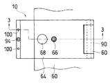
図1から図8を参照するに、プローブ装置10は、一部を図5に示す液晶パネル12の検査装置、特に点灯すなわち通電検査装置に用いられる。液晶パネル12は、長方形の形状をしており、また複数の電極14を長方形の隣り合う2つの辺に対応する縁部に所定のピッチで形成している。
【0029】
プローブ装置10は、プローブブロック16を含む。プローブブロック16は、図示の例では、プローブシート18と、プローブシート18に接続されたシート状の第1の接続シート20と、第1の接続シート20に接続された第2の接続シート22と、それらシート18,20及び22が装着されたプローブホルダ24とにより形成されている。
【0030】
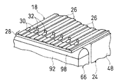
プローブシート18は、その前端部を図6に示すように、互いに並列的に前後方向へ伸びる複数の配線26を印刷配線技術によりポリイミドのような電気絶縁性フィルム28の一方の面に形成したフィルム状プローブユニットである。プローブシート18は、平面的にみて配線26の配列方向(左右方向)に長い長方形の形状を有する。各配線26は、フィルム28の前端から後端まで伸びている。配線26の配列ピッチは、液晶パネル12の電極14の配列ピッチと同じである。
【0031】
プローブシート18は、また、突起電極30を各配線26の前端部に有する。各突起電極30は、ニッケルのような導電性金属材料から形成されており、また半球状の形状を有する。しかし、突起電極30は、短い円柱状、短い多角柱状、直方体状、リング状等、他の形状を有していてもよい。
【0032】
プローブシート18は、さらに、隣り合う配線26の間を伸びるスリット32を前端部、特に突起電極30の形成位置に対応する箇所に有する。各スリット32は、フィルム28を貫通している。そのようなスリット32は、レーザ加工、エッチング加工等の適宜な加工技術によりフィルム28に形成される。
【0033】
第1の接続シート20は、図2に示すように、複数の配線34及び36を印刷配線技術によりポリイミドのような電気絶縁性フィルム38の一方の面に形成したタブ(TAB)であり、また配線34,36に電気的に接続された駆動用集積回路40を一方の面に有する。
【0034】
第1の接続シート20の各配線34は、プローブシート18の配線26に一対一の形に対応されており、対応する配線26に電気的に接続されている。集積回路40は、液晶パネル12の駆動に用いられ、駆動用制御信号を配線36から受けて、駆動信号を配線34に出力する。
【0035】
第2の接続シート22は、図2に示すように、複数の配線42を印刷配線技術によりポリイミドのような電気絶縁性フィルム44の一方の面に形成したフラットケーブル(FPC)である。第2の接続シート22の各配線42は、第1の接続シート20の配線36に一対一の形に対応されており、対応する配線36に電気的に接続されている。
【0036】
プローブホルダ24は、図3に示すように、ほぼ水平の板状部46と、その前端から下方へ伸びる板状の取付部48とにより、逆L字状の形状をしており、また電気絶縁材料により形成されている。板状部46及び取付部48の下面は、いずれも平坦面とされている。
【0037】
板状部46の後端上部には、上方及び後方に開口するL字状の断面形状を有する段部50が形成されている。この段部50には、円形の断面形状を有する棒状の弾性体52が配置されている。弾性体52は、シリコーンゴムのようなゴムで形成することができる。
【0038】
プローブシート18は、その前端部が取付部48の前方へ突出しかつ配線26がフィルム28より下方となる状態に、フィルム28において取付部48の下面に接着剤のような適宜な手段により装着されている。接続シート20及び22は、配線36及び42が下側となる状態に、フィルム38において板状部46の下面に接着のような適宜な手段により装着されている。
【0039】
各配線26の前端部、その前端部に対応するフィルム28の部位及び突起電極30は、プローブ要素として作用する。したがって、プローブシート18の前端部、特に突起電極30及びスリット32が形成された領域は、プローブ領域として作用する。フィルム28の少なくとも前端部は、透明又は半透明とすることができる。
【0040】
プローブシート18の後端部は上側に折り返されている。各配線26は、折り返された箇所において接続シート20の対応する配線34に、加熱圧着(又は半田のような導電性接着剤)により電気的に接続されている。接続シート20及び22の配線36及び42は、接続シート20及び22が板状部46に取り付けられる前に、導電性のスルーホールや半田のような適宜な手段により電気的に接続しておくことができる。
【0041】
図3,図4及び図5に示すように、プローブホルダ24は、また、左右方向の中央を前後方向へ伸びる凸部54を板状部46の上面に備えていると共に、上方及び後方に開口する溝56を凸部54に備えており、さらに上下方向へ伸びる棒状のストッパ58を凸部54の前端部上面に有している。凸部54は直方体状の形状をしており、また溝56は凸字状(逆T字状)の断面形状をしている。
【0042】
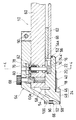
プローブ装置10は、また、プローブホルダ24が結合された板状のブロックホルダすなわちプローブベース60と、複数のねじ部材によりプローブベース60の下側に結合された配線部材62と、プローブベース60に連結されたアーム64と、アーム64の前端部に配置されてプローブシート18の前端部を下方へ押する押圧機構66と、押圧機構66がプローブシート18を押圧している状態に解除可能にアーム64を維持するねじ部材68とを含む。
【0043】
プローブベース60は、一対のガイド70をプローブブロック16毎に前部下面に取り付けていると共に、1以上のプランジャ72をプローブブロック16毎に一方のガイド70に設けている。両ガイド70は、プローブホルダ24の凸部54を受け入れる凹所を形成するように、左右方向へ間隔をおいて前後方向へ平行に伸びている。
【0044】
プランジャ72は、止め具、ボール、及び、止め具とボールとの間にあってボールを止め具と反対の側に押す弾性体を中空のシリンダ内に配置した市販のものであり、プローブホルダ24の凸部54を他方のガイド70に向けて付勢するように、一方のガイド70に組み付けられている。
【0045】
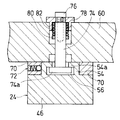
図4に示すように、プローブホルダ24をプローブベース60の下側に解除可能に組み付ける組み付け手段は、プローブベース60を厚さ方向に移動可能に貫通する第1のねじ部材74と、プローブベース60の上側にあって第1のねじ部材74に螺合された第2のねじ部材76と、第1のねじ部材74の上部が貫通するキャップ78とを備える。
【0046】
第1のねじ部材74は、フランジ状の頭部74aを下端に有しており、また下端部を溝56に該溝56の長手方向へ相対的に移動可能に受け入れられている。第2のねじ部材76は、第1のねじ部材74に形成されたねじ穴に上方から螺合されている。
【0047】
第1のねじ部材74の長手方向中間部には、止めリング80が組み付けられている。止めリング80とキャップ78との間には、弾性部材82が第1のねじ部材74を常時下方へ付勢するように配置されている。弾性部材82は、図示の例では圧縮コイルばねであるが、ゴムのような他の部材であってもよい。
【0048】
第1のねじ部材74が弾性部材82により常時下方へ付勢されているため、プローブベース60の下面と第1のねじ部材74の頭部74aとの間隔は、第1のねじ部材74に対する第2のねじ部材76のねじ込み量を調整することにより、調整することができる。溝56の上面を形成している部位54aは、プローブベース60と第1のねじ部材74の頭部74aとに挟まれている。
【0049】
配線部材62は、図2に示すように、複数の配線84を印刷配線技術のような適宜な手法により電気絶縁性基板86の一方の面に平行に形成した接続基板である。配線部材62は、図3に示すように、配線84が下方となる状態にプローブベース60の下面にスペーサ88を介して組み付けられている。
【0050】
配線部材62の各配線84は、第2の接続シート22の後端部が上側に折り返されて、弾性体52によって第2の接続シート22に押圧されていることにより、第2の接続シート22の対応する配線42に電気的に接続されている。
【0051】
アーム64は、前部及び後部によりほぼへ字状の形をしており、また左右方向へ伸びる枢軸90により、後部がプローブベース60の上側となりかつ前部がプローブホルダ24及びプローブベース60の前側を斜め下方へ伸びる状態に後部においてプローブベース60に結合されている。
【0052】
アーム64は、第2のねじ部材76を操作する六角レンチのような工具を通す穴と、ねじ部材68が貫通する穴とを後部に有する。ねじ部材68は、プローブベース60に形成されたねじ穴に螺合されている。
【0053】
押圧機構66は、アーム64の先端部下側に配置されたベース部材92と、アーム64の前端部を上下方向に貫通してベース部材92に螺合する1以上の調整ねじ94と、アーム64とベース部材92との間に配置されてベース部材92をアーム64に対し下方へ付勢する1以上の第1の弾性体96と、ベース部材92に配置されてプローブシート18の前端部上面に接触する第2の弾性体98と、調整ねじ94を間にして左右方向に間隔をおいて上下方向へ伸びる複数のガイドピン100とを備える。
【0054】
ベース部材92は、左右方向へ伸びており、また調整ねじ94及びガイドピン100によりアーム64に上下方向へ移動可能に組み付けられている。ガイドピン100は、アーム64及びベース部材92のいずれか一方に支持されていると共にアーム64及びベース部材92の他方に上下方向へ相対的移動可能に受け入れられており、また第1の弾性体96を貫通して伸びている。
【0055】
第1の弾性体96は、図示の例では圧縮コイルばねであるが、ゴムのような他の部材であってもよい。第2の弾性体98は、シリコーンゴムのような弾性材料により蒲鉾型に形成されており、またベース部材92の下面に左右方向へ伸びる状態に配置されている。
【0056】
図9〜図13に示すように、複数のプローブブロック16と、複数の配線部材62と、複数のアーム64と、複数の押圧機構66とが共通のプローブベース60に左右方向に組み付けられている。プローブベース60の前端面は、複数のストッパ58が共に当接するストッパ面60aとして作用するように、平坦面とされている。
【0057】
検査時、プローブ装置10と液晶パネル12とは、相寄る方向へ相対的に移動される。これにより、先ず各突起電極30が液晶パネル12の電極14に接触され、次いでオーバードライブがプローブシート18の先端部すなわちプローブ領域に作用する。その状態で各配線に通電されて、液晶パネル12の検査が行われる。その結果、プローブシート18の前端部は、弾性体96の力に抗して弾性変形するが、プローブ装置10と液晶パネル12との相対的な押圧が解除されることにより、元の形状に戻る。
【0058】
プローブシート18の突起電極30が液晶パネル12の電極14に押圧されたとき、アーム64及び押圧機構66は、プローブシート18の前端部がその後方の部位に対し大きく曲げられることを防止する。また、プローブシート18の突起電極30が液晶パネル12の電極14に押圧されたとき、弾性体98が弾性変形するから、突起電極30と電極14との間の接触圧(針圧)が大きくなる。
【0059】
プローブシート18のプローブ領域が弾性変形するとき、各プローブ領域はスリット32により独立して変形する。この際、各プローブ要素は、弾性体98の対応する箇所を圧縮変形させつつ、弾性変形するから、プローブ要素の左右方向への変位を、隣り合うプローブ要素の先端が切り離されていないことと相まって、弾性体98により阻止される。
【0060】
プローブシート18のフィルム28がポリイミドのような透明材料製又は他のフィルムのような半透明材料製であると、図5に示すように、液晶パネル12の電極14とプローブシート18の突起電極30とを接触させるとき、プローブシート18の配線26と液晶パネル12の電極14との位置関係を、取付部48より前方に突出するプローブシート18の前端部を通して確認することができる。
【0061】
プローブブロック16をプローブベース60に組み付けるとき、図9及び図10に示すように、ねじ部材68がプローブベース60から外されてアーム64が立ち上げられていると共に、第2のねじ部材76が緩められて第1のねじ部材74が下方へ移動されている。
【0062】
この状態でストッパ58がプローブベース60の前端面すなわちストッパ面60aに当接するまで、プローブブロック16の凸部54を前方から両ガイド70の間に差し込まれる。これにより、プローブブロック16は図11に示すようにプローブベース60に配置される。
【0063】
前後方向におけるプローブブロック16の位置決めは、ストッパ58がプローブベース60のストッパ面60aに当接することにより行われる。左右方向におけるプローブブロック16の位置決めは、図13に示すように、凸部54がプランジャ72によりそれと反対側のガイド70に押し当てられることにより行われる。このため、プローブブロック16の位置決めをワンタッチで行うことができる。
【0064】
プローブブロック16をプローブベース60に装着するとき、第1のねじ部材74が弾性部材82により押し下げられているから、溝56の上面を形成している部位54aはプローブベース60と第1のねじ部材74の頭部74aとの間に確実に受け入れられる。
【0065】
プローブブロック16がプローブベース60に上記のように装着された状態において、第2のねじ部材76が第1のねじ部材74に強く螺合されて、溝56の上面を形成している部位54aがプローブベース60と第1のねじ部材74の頭部74aとの間に強く挟み込まれる。これにより、プローブブロック16は、図3及び図4に示すようにプローブベース60に移動不能に及び解除可能に強く組み付けられる。
【0066】
次いで、アーム64が図12に示すように所定の位置に変位され、ねじ部材68がプローブベース60のねじ穴に螺合される。これにより、アーム64及び押圧機構66が所定の位置に維持される。この状態において、押圧機構66の第2の弾性体98は、プローブシート18の先端部に当接している。
【0067】
その後、押圧機構66によるプローブシート18の押圧力が調整ねじ94により調整調整される。
【0068】
プローブブロック16をプローブベース60から外すときは、ねじ部材68をプローブベース60から外してアーム64を上げ、第2のねじ部材76を緩めてプローブホルダ24の部位54aを第1のねじ部材74の頭部74aとプローブベース60とによる挟持から解除し、その後プローブブロック16を前方へ引き出せばよい。
【0069】
プローブブロックを交換するときは、プローブベース60に組み付けられているプローブブロックを上記のように取り外し、次いで新たなプローブブロックをプローブベース60に上記のように組み付ければよい。
【0070】
上記のようにプローブ装置10によれば、第1及び第2のねじ部材74,76の締め緩めをすると共に、プローブブロック16をプローブベース60に対し前後方向へ移動させることにより、プローブブロック16をプローブベース60に対し着脱することができるから、プローブベース60へのプローブブロック16の着脱作業が容易になる。
【0071】
また、プローブブロック16の凸部54をプローブベース60のガイド70の間に差し込むだけで、左右方向及び前後方向におけるプローブブロック16の位置決めが行われるから、プローブブロック16の交換作業がより容易になる。
【0072】
さらに、アームを上げた状態で、プローブベース60に対するプローブブロック16の着脱作業を行うことができるから、アーム64及び押圧機構66はプローブホルダ16の着脱の妨げにならない。
【0073】
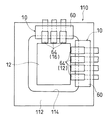
図14は、上記した構造を有する複数のプローブ装置10を用いて、液晶パネル12を検査するプローブカード110の一実施例を示す。ベース板112は、長方形の開口114を中央に有しており、4つのプローブ装置10を組み付けたプローブベース60を長方形の長辺に対応する箇所に配置し、3つのプローブ装置10を組み付けたプローブベース60を長方形の短辺に対応する箇所に配置している。両プローブベース60は、各プローブ装置10の少なくともプローブシート18が開口114に突出する状態にベース板112に配置されている。
【0074】
上記実施例においては、プローブシート18の前端部を押圧機構66から前方へ突出させているが、プローブシート18の前端部を押圧機構66から前方へ突出させていなくてもよい。
【0075】
本発明は、液晶パネルの検査装置に用いるプローブ装置に適用すると、シート状部材としてタブ(TAB)を用いることができることから好適である。しかし、本発明は、集積回路のような他の平板状被検査体の検査に用いるプローブ装置にも適用することができる。
【0076】
本発明は、水平に配置された被検査体用のプローブ装置のみならず、斜めに傾斜された被検査体用のプローブ装置にも適用することができる。本発明においては、被検査体と平行な面内における一方向及び他方向をそれぞれ前後方向及び左右方向といい、被検査体に垂直な方向を上下方向というから、後者の場合、上下方向は斜めの方向となる。
【0077】
本発明は、上記実施例に限定されず、その趣旨を逸脱しない限り、種々変更することができる。
【図面の簡単な説明】
【図1】本発明に係るプローブ装置の一実施例を示す平面図
【図2】図1に示すプローブ装置の底面図
【図3】図1の3−3線に沿って得た断面図
【図4】図3の4−4線に沿って得た断面図
【図5】プローブブロックの一実施例を示す斜視図
【図6】図1に示すプローブ装置の先端部分を上下逆にして示す斜視図
【図7】プローブブロックの後端部の拡大断面図
【図8】押圧機構の拡大断面図
【図9】プローブブロックをプローブベースに装着する状態を示す断面図
【図10】プローブブロックをプローブベースに装着する状態を示す斜視図
【図11】プローブブロックをプローブベースに装着した状態を示す斜視図
【図12】アームをプローブベースに正しく組み付けた状態を示す斜視図
【図13】左右方向におけるプローブブロックの位置決め状態を説明するための図
【図14】複数のプローブ装置を用いたプローブカードの一実施例を示す平面図
【符号の説明】
10 プローブ装置
12 液晶パネル
14 液晶パネルの電極
16 プローブブロック
18 プローブシート
20,22 接続シート
24 プローブホルダ
26 プローブシートの配線
28 プローブシートのフィルム
30 突起電極
32 スリット
34,36,42 接続シートの配線
38,44 接続シートのフィルム
46 プローブホルダの平板部
48 プローブホルダの取付部
54 凸部
56 溝
58 ストッパ
60 プローブベース
60a ストッパ面
62 配線部材
64 アーム
66 押圧機構
68 ねじ部材
70 ガイド
72 プランジャ
74 第1のねじ部材
74a 第1のねじ部材の頭部
76 第2のねじ部材
82 弾性部材
92 ベース部材
94 調整ねじ
96,98 第1及び第2の弾性体
100 ガイドピン[0001]
BACKGROUND OF THE INVENTION
The present invention relates to a probe apparatus used for inspecting a plate-like object such as a liquid crystal panel and an integrated circuit.
[0002]
In the present invention, one direction and the other direction in a plane parallel to the object to be inspected are referred to as the front-rear direction (first direction) and the left-right direction (second direction), respectively, and the direction perpendicular to the object to be inspected is up and down. It is called direction (third direction).
[0003]
[Prior art]
In general, flat inspection objects such as integrated circuits and liquid crystal panels are inspected using a probe device such as a probe card. One type of this type of probe device uses a probe sheet in which a plurality of wirings extending in parallel with each other are formed on one surface of an electrically insulating film and a part of each wiring is used as a probe element.
[0004]
The probe device using such a probe sheet does not require a needle stand operation as compared with a needle type probe device using a probe formed from a thin metal wire and a blade type probe device using a blade-like probe. Therefore, it is easy to manufacture and inexpensive.
[0005]
Various probe devices using a probe sheet have been proposed and put into practical use. Such probe devices generally have one or more probe sheets assembled on a common substrate. However, since the size of the object to be inspected, the number of electrodes, the arrangement pitch of the electrodes, and the like vary depending on the type of the object to be inspected, in the conventional probe device, each time the type of the object to be inspected is changed, It must be replaced with a probe device corresponding to the object to be inspected.
[0006]
Such replacement of the probe device becomes more difficult as the probe device becomes larger. In particular, in a probe device for a liquid crystal panel, since the liquid crystal panel itself is large, the probe device itself becomes large and replacement is more difficult.
[0007]
[Problems to be solved]
As in the case of a needle type probe device, it is conceivable to divide the probe elements into a plurality of element groups by removably assembling a plurality of probe blocks having probe sheets arranged on the probe holder to the probe base.
[0008]
In such a probe device, it is important to facilitate attachment / detachment of each probe block to / from the probe base.
[0009]
[Solution, action and effect]
A probe device according to the present invention includes a probe sheet in which a plurality of wirings extending in the front-rear direction at intervals in the left-right direction are formed on an electrically insulating film, and a mounting portion having a lower surface on which the probe sheet is mounted. A probe holder provided on the upper surface, and a probe holder provided on the upper surface with one of a convex portion extending in the front-rear direction and a concave portion extending in the front-rear direction to receive the convex portion, and the probe holder is disposed A plate-like probe base, which is provided with the other of the convex portion and the recess on the lower side, and one or more screw members for releasably assembling the probe holder to the lower side of the probe base. Assembly means provided.
[0010]
In the probe sheet, the probe device and the object to be inspected are relatively moved in the vertical direction, whereby the contact portion at the tip of each wiring is pressed against the electrode of the object to be inspected. In this state, each wiring is energized, and the inspection object is inspected.
[0011]
When the type of the object to be inspected is changed or the probe sheet is damaged, the probe sheet and the probe holder are exchanged. This replacement work is performed as follows.
[0012]
First, the screw member of the assembly means is loosened. Thereby, the assembly of the probe holder to the probe base is released.
[0013]
Next, the probe holder is pulled forward from the probe base together with the probe sheet attached thereto. Thereby, the probe holder is removed from the probe base.
[0014]
Next, a new probe holder equipped with a probe sheet corresponding to the type of the object to be inspected is placed on the probe base. At this time, the probe holder is moved from the front to the rear with respect to the probe base in a state where the convex portion formed on one of the probe holder and the probe base is fitted in the recess formed on the other.
[0015]
Next, the probe holder is assembled so as to be immovable on the probe base by the screw member of the assembling means.
[0016]
As described above, according to the present invention, the probe holder can be attached to and detached from the probe base by tightening and loosening the screw member and moving the probe holder in the front-rear direction with respect to the probe base. The probe holder can be easily attached and detached.
[0017]
In the probe apparatus according to the present invention, the probe holder further includes a groove that opens upward and rearward, has a convex cross-sectional shape and extends in the front-rear direction, and the screw member includes: The first screw member that penetrates the probe base in the thickness direction, has a flange-shaped head at the lower end, and the lower end is received in the groove so as to be relatively movable in the longitudinal direction of the groove. A first screw member; and a second screw member that is above the probe base and screwed into the first screw member. Therefore, according to the present invention, the probe holder can be moved to the probe base by sandwiching the portion forming the upper surface of the groove of the probe holder between the head of the first screw member and the probe base. Can be assembled. In addition, by loosening the screwing of the first and second screw members, the portion forming the upper surface of the groove of the probe holder is released from clamping between the head of the first screw member and the probe base, The assembly of the probe holder to the probe base can be released. As a result, the assembly and release of the probe holder with respect to the probe base is facilitated.
[0018]
The assembly means may further include an elastic member that constantly urges the second screw member downward. By doing so, the interval between the head of the first screw member and the probe base is naturally increased by loosening the screwing of the first and second screw members. The probe holder can be arranged on the probe base simply by moving it in the front-rear direction.
[0019]
The probe holder and the probe base may further include a stopper portion that abuts each other when the probe holder is moved rearward with respect to the probe base in a state where the convex portion is received in the recess. If it does in that way, if both stoppers contact | abut, since the movement of a probe holder to the back will be prevented, a probe holder will be positioned in the front-back direction with respect to a probe base.
[0020]
The probe device may further include one or more plungers that urge the probe holder toward the one side in the left-right direction with respect to the probe base. By doing so, one side wall of the recess in the left-right direction and one side wall of the convex portion in the left-right direction come into contact with each other, whereby the probe holder is positioned in the left-right direction with respect to the probe base.
[0021]
In a preferred embodiment, the probe sheet has its front end protruding forward from the probe holder. However, the probe sheet may not have its front end portion projected forward from the probe holder.
[0022]
The probe device further includes an arm having a front portion and a rear portion, wherein the rear portion is located above the probe base and is pivotable about an axis extending in the left-right direction at the rear portion to the probe base. A coupled arm; a pressing mechanism disposed at a front end portion of the arm to press the front end portion of the probe sheet downward; and the arm releasable to a state where the pressing mechanism presses the probe sheet. A third screw member to be maintained. By doing so, when the probe holder is attached to or detached from the probe base, the arm can be displaced to a position that does not hinder the attachment or detachment of the probe holder. Moreover, when the contact part of a probe sheet is pressed by the electrode of a to-be-inspected object, it is prevented that the front-end part of a probe sheet is largely bent with respect to the site | part of the back.
[0023]
The pressing mechanism is a base member extending in the left-right direction, and is disposed at the tip end portion of the arm so as to be movable in the vertical direction, and the height position of the base member with respect to the front end portion of the probe sheet. One or more adjustment screws that pass vertically through the front end of the arm to be adjusted and screwed into the base member, and the base member is disposed between the arm and the base member. One or more first elastic bodies that urge downward may be provided, and a second elastic body that is disposed on the base member and contacts the upper surface of the front end portion of the probe sheet. If it does in that way, the height position of the press mechanism with respect to a probe base can be adjusted with a screw member by adjusting the screwing amount of the adjustment screw to a base member. Further, when the contact portion of the probe sheet is pressed against the electrode of the object to be inspected, the second elastic body is elastically deformed, so that the contact pressure (needle pressure) between the contact portion and the electrode increases.
[0024]
The pressing mechanism further includes a plurality of guide pins extending in the vertical direction at intervals in the left-right direction, the guide pins being supported by either the arm or the base member, The other base member is received so as to be relatively movable in the vertical direction, and may extend through the first elastic body.
[0025]
In a preferred embodiment, the lower surface of the attachment portion has a rectangular shape that is long in the left-right direction. The probe sheet has a protruding electrode at the tip of each wiring, and this protruding electrode is used as a contact portion. Further, the probe sheet has a slit extending in the front-rear direction between adjacent wirings at the position of the film corresponding to the arrangement position of the contact portion.
[0026]
The probe device further includes a connection sheet having a plurality of second wirings extending in parallel with each other on one surface of the electrically insulating film, the connection member being mounted on the probe holder, and a rear portion of the probe sheet The wiring sheet may be bent or folded upward, and each wiring may be individually connected to the second wiring at a folded portion or a folded portion. The probe device may further include a connection member having a plurality of third wirings individually connected to the second wiring.
[0027]
The front edge of the probe sheet may protrude forward from the attachment portion, and at least a portion of the film in front of the attachment portion may be transparent or translucent. In this way, the positional relationship between the wiring of the probe sheet and the electrode of the object to be inspected can be confirmed through the transparent or translucent portion of the film in front of the mounting portion. Alignment with the electrode becomes easy.
[0028]
DETAILED DESCRIPTION OF THE INVENTION
Referring to FIGS. 1 to 8, the
[0029]
The
[0030]
As shown in FIG. 6, the
[0031]
The
[0032]
The
[0033]
As shown in FIG. 2, the
[0034]
Each
[0035]
As shown in FIG. 2, the
[0036]
As shown in FIG. 3, the
[0037]
A
[0038]
The
[0039]
The front end portion of each
[0040]
The rear end portion of the
[0041]
As shown in FIGS. 3, 4, and 5, the
[0042]
The
[0043]
The
[0044]
The
[0045]
As shown in FIG. 4, the assembly means for releasably assembling the
[0046]
The
[0047]
A
[0048]
Since the
[0049]
As shown in FIG. 2, the
[0050]
Each
[0051]
The
[0052]
The
[0053]
The
[0054]
The
[0055]
The first
[0056]
As shown in FIGS. 9 to 13, a plurality of probe blocks 16, a plurality of
[0057]
At the time of inspection, the
[0058]
When the protruding
[0059]
When the probe region of the
[0060]
When the
[0061]
When the
[0062]
In this state, the
[0063]
Positioning of the
[0064]
When the
[0065]
In the state where the
[0066]
Next, the
[0067]
Thereafter, the pressing force of the
[0068]
When removing the
[0069]
When exchanging the probe block, the probe block assembled to the
[0070]
As described above, according to the
[0071]
Further, since the
[0072]
Furthermore, since the
[0073]
FIG. 14 shows an embodiment of a
[0074]
In the above embodiment, the front end portion of the
[0075]
When the present invention is applied to a probe device used in a liquid crystal panel inspection device, a tab (TAB) can be used as a sheet-like member. However, the present invention can also be applied to a probe apparatus used for inspecting other plate-shaped inspected objects such as integrated circuits.
[0076]
The present invention can be applied not only to a probe device for an object to be inspected horizontally but also to a probe device for an object to be inspected obliquely. In the present invention, one direction and the other direction in a plane parallel to the object to be inspected are referred to as the front-rear direction and the left-right direction, respectively, and the direction perpendicular to the object to be inspected is referred to as the up-down direction. Direction.
[0077]
The present invention is not limited to the above embodiments, and various modifications can be made without departing from the spirit of the present invention.
[Brief description of the drawings]
FIG. 1 is a plan view showing an embodiment of a probe apparatus according to the present invention.
FIG. 2 is a bottom view of the probe device shown in FIG.
3 is a cross-sectional view taken along line 3-3 in FIG.
4 is a cross-sectional view taken along line 4-4 of FIG.
FIG. 5 is a perspective view showing an embodiment of a probe block.
6 is a perspective view showing the tip portion of the probe device shown in FIG. 1 upside down. FIG.
FIG. 7 is an enlarged cross-sectional view of the rear end of the probe block
FIG. 8 is an enlarged sectional view of the pressing mechanism.
FIG. 9 is a sectional view showing a state in which the probe block is attached to the probe base.
FIG. 10 is a perspective view showing a state in which the probe block is mounted on the probe base.
FIG. 11 is a perspective view showing a state in which the probe block is mounted on the probe base.
FIG. 12 is a perspective view showing a state in which the arm is correctly assembled to the probe base.
FIG. 13 is a view for explaining the positioning state of the probe block in the left-right direction.
FIG. 14 is a plan view showing an embodiment of a probe card using a plurality of probe devices.
[Explanation of symbols]
10 Probe device
12 LCD panel
14 LCD panel electrodes
16 Probe block
18 Probe sheet
20,22 Connection sheet
24 Probe holder
26 Probe sheet wiring
28 Probe sheet film
30 Projection electrode
32 slits
34, 36, 42 Wiring of connection sheet
38,44 Connection sheet film
46 Flat part of the probe holder
48 Probe holder mounting
54 Convex
56 groove
58 Stopper
60 probe base
60a Stopper surface
62 Wiring member
64 arms
66 Pressing mechanism
68 Screw member
70 Guide
72 Plunger
74 First screw member
74a Head of first screw member
76 Second screw member
82 Elastic member
92 Base member
94 Adjustment screw
96, 98 First and second elastic bodies
100 guide pins
Claims (7)
前記プローブシートが装着された下面を有する取付部を前部に備えるプローブホルダであって前後方向に延在する凸部及び該凸部を受け入れるべく前後方向に延在する凹所のいずれか一方を上面に備えるプローブホルダと、
該プローブホルダが配置された板状のプローブベースであって前記凸部及び前記凹所の他方を下側に備える板状のプローブベースと、
前記プローブホルダを前記プローブベースの下側に解除可能に組み付ける1以上のねじ部材を備える組み付け手段とを含み、
前記プローブホルダは、さらに、上方及び後方に開放する溝であって凸字状の断面形状を有しかつ前後方向に延在する溝を備え、
前記ねじ部材は、前記プローブベースを厚さ方向に貫通する第1のねじ部材であってフランジ状の頭部を下端に有しかつ下端部を前記溝に該溝の長手方向へ相対的に移動可能に受け入れられた第1のねじ部材と、前記プローブベースの上側にあって前記第1のねじ部材に螺合された第2のねじ部材とを備える、プローブ装置。A probe sheet in which a plurality of wires extending in the front-rear direction at intervals in the left-right direction are formed on the electrically insulating film;
A probe holder having a mounting portion having a lower surface on which the probe sheet is mounted at a front portion, and having either one of a convex portion extending in the front-rear direction and a concave portion extending in the front-rear direction to receive the convex portion A probe holder provided on the upper surface;
A plate-like probe base on which the probe holder is disposed, and a plate-like probe base provided with the other of the convex portion and the concave portion on the lower side;
Assembly means comprising one or more screw members for releasably assembling the probe holder to the lower side of the probe base;
The probe holder further includes a groove that opens upward and rearward, has a convex cross-sectional shape, and extends in the front-rear direction.
The screw member is a first screw member that penetrates the probe base in the thickness direction, has a flange-shaped head at the lower end, and moves the lower end relative to the groove in the longitudinal direction of the groove. A probe device, comprising: a first screw member that is accepted, and a second screw member that is above the probe base and screwed into the first screw member.
Priority Applications (3)
| Application Number | Priority Date | Filing Date | Title |
|---|---|---|---|
| JP32277799A JP4171148B2 (en) | 1999-11-12 | 1999-11-12 | Probe device |
| TW089103647A TW533309B (en) | 1999-06-22 | 2000-03-02 | Probe device |
| KR1020000011010A KR100340466B1 (en) | 1999-06-22 | 2000-03-06 | Probe apparatus |
Applications Claiming Priority (1)
| Application Number | Priority Date | Filing Date | Title |
|---|---|---|---|
| JP32277799A JP4171148B2 (en) | 1999-11-12 | 1999-11-12 | Probe device |
Publications (3)
| Publication Number | Publication Date |
|---|---|
| JP2001141747A JP2001141747A (en) | 2001-05-25 |
| JP2001141747A5 JP2001141747A5 (en) | 2005-08-11 |
| JP4171148B2 true JP4171148B2 (en) | 2008-10-22 |
Family
ID=18147537
Family Applications (1)
| Application Number | Title | Priority Date | Filing Date |
|---|---|---|---|
| JP32277799A Expired - Lifetime JP4171148B2 (en) | 1999-06-22 | 1999-11-12 | Probe device |
Country Status (1)
| Country | Link |
|---|---|
| JP (1) | JP4171148B2 (en) |
Families Citing this family (10)
| Publication number | Priority date | Publication date | Assignee | Title |
|---|---|---|---|---|
| JP2003098189A (en) * | 2001-09-26 | 2003-04-03 | Micronics Japan Co Ltd | Probe sheet and probe device |
| JP4443916B2 (en) * | 2003-12-25 | 2010-03-31 | 株式会社日本マイクロニクス | Probe device |
| JP2005300409A (en) * | 2004-04-14 | 2005-10-27 | Nhk Spring Co Ltd | Inspection unit |
| KR100638106B1 (en) | 2005-06-21 | 2006-10-24 | 주식회사 코디에스 | Probe unit for inspection of flat panel display devices |
| KR100833813B1 (en) | 2007-04-13 | 2008-05-30 | 나노세미텍(주) | Probe block with aeolotropy silicon connect and shift type joint plate |
| JP2010127706A (en) * | 2008-11-26 | 2010-06-10 | Micronics Japan Co Ltd | Probe unit and inspection apparatus |
| JP2012078222A (en) | 2010-10-01 | 2012-04-19 | Fujifilm Corp | Circuit substrate connection structure and circuit substrate connecting method |
| KR101420076B1 (en) | 2014-06-03 | 2014-08-14 | 김재길 | Probe card in directly connecting type |
| JP6390354B2 (en) * | 2014-11-06 | 2018-09-19 | オムロン株式会社 | Terminal fixing device and terminal fixing method |
| CN109870658A (en) * | 2019-02-14 | 2019-06-11 | 株洲福德轨道交通研究院有限公司 | Needle bed mechanism |
-
1999
- 1999-11-12 JP JP32277799A patent/JP4171148B2/en not_active Expired - Lifetime
Also Published As
| Publication number | Publication date |
|---|---|
| JP2001141747A (en) | 2001-05-25 |
Similar Documents
| Publication | Publication Date | Title |
|---|---|---|
| JP4171148B2 (en) | Probe device | |
| JP2008275406A (en) | Probe device and inspection device | |
| KR100340466B1 (en) | Probe apparatus | |
| JP3976276B2 (en) | Inspection device | |
| KR100314874B1 (en) | Probing apparatus | |
| JP2001004662A (en) | Probe device | |
| JP4545742B2 (en) | Electrical connection device | |
| JP4313565B2 (en) | Probe device | |
| JP4455733B2 (en) | Probe sheet and probe apparatus using the same | |
| JP4443916B2 (en) | Probe device | |
| JP2003098189A (en) | Probe sheet and probe device | |
| JP4634059B2 (en) | Probe assembly | |
| JP2001141747A5 (en) | ||
| JP4046929B2 (en) | Electrical connection sheet | |
| JP3829099B2 (en) | Electrical connection device | |
| JPWO2006114885A1 (en) | Electrical connection device | |
| TWI420112B (en) | Probe device | |
| JP4053790B2 (en) | Display board inspection socket | |
| JP5308958B2 (en) | Work table and display device for display panel | |
| JP2011112491A (en) | Probe device | |
| JP2002181866A (en) | Inspecting socket for display substrate | |
| JP2002196029A (en) | Device for inspecting substrate for display | |
| JPS63302377A (en) | Apparatus for inspecting circuit board | |
| JP2002350485A (en) | Inspection device for display substrate | |
| JPH0712949Y2 (en) | Board-to-board connection device |
Legal Events
| Date | Code | Title | Description |
|---|---|---|---|
| A521 | Written amendment |
Free format text: JAPANESE INTERMEDIATE CODE: A523 Effective date: 20050124 |
|
| A621 | Written request for application examination |
Free format text: JAPANESE INTERMEDIATE CODE: A621 Effective date: 20050124 |
|
| A977 | Report on retrieval |
Free format text: JAPANESE INTERMEDIATE CODE: A971007 Effective date: 20070402 |
|
| A131 | Notification of reasons for refusal |
Free format text: JAPANESE INTERMEDIATE CODE: A131 Effective date: 20080422 |
|
| A521 | Written amendment |
Free format text: JAPANESE INTERMEDIATE CODE: A523 Effective date: 20080610 |
|
| TRDD | Decision of grant or rejection written | ||
| A01 | Written decision to grant a patent or to grant a registration (utility model) |
Free format text: JAPANESE INTERMEDIATE CODE: A01 Effective date: 20080722 |
|
| A01 | Written decision to grant a patent or to grant a registration (utility model) |
Free format text: JAPANESE INTERMEDIATE CODE: A01 |
|
| A61 | First payment of annual fees (during grant procedure) |
Free format text: JAPANESE INTERMEDIATE CODE: A61 Effective date: 20080808 |
|
| FPAY | Renewal fee payment (event date is renewal date of database) |
Free format text: PAYMENT UNTIL: 20110815 Year of fee payment: 3 |
|
| R150 | Certificate of patent or registration of utility model |
Ref document number: 4171148 Country of ref document: JP Free format text: JAPANESE INTERMEDIATE CODE: R150 Free format text: JAPANESE INTERMEDIATE CODE: R150 |
|
| FPAY | Renewal fee payment (event date is renewal date of database) |
Free format text: PAYMENT UNTIL: 20140815 Year of fee payment: 6 |
|
| R250 | Receipt of annual fees |
Free format text: JAPANESE INTERMEDIATE CODE: R250 |
|
| R250 | Receipt of annual fees |
Free format text: JAPANESE INTERMEDIATE CODE: R250 |
|
| R250 | Receipt of annual fees |
Free format text: JAPANESE INTERMEDIATE CODE: R250 |
|
| R250 | Receipt of annual fees |
Free format text: JAPANESE INTERMEDIATE CODE: R250 |
|
| R250 | Receipt of annual fees |
Free format text: JAPANESE INTERMEDIATE CODE: R250 |
|
| EXPY | Cancellation because of completion of term |