JP4126978B2 - Preform, FRP comprising the same, and method for producing FRP - Google Patents
Preform, FRP comprising the same, and method for producing FRP Download PDFInfo
- Publication number
- JP4126978B2 JP4126978B2 JP2002196838A JP2002196838A JP4126978B2 JP 4126978 B2 JP4126978 B2 JP 4126978B2 JP 2002196838 A JP2002196838 A JP 2002196838A JP 2002196838 A JP2002196838 A JP 2002196838A JP 4126978 B2 JP4126978 B2 JP 4126978B2
- Authority
- JP
- Japan
- Prior art keywords
- preform
- frp
- fabric
- reinforcing
- reinforcing fiber
- Prior art date
- Legal status (The legal status is an assumption and is not a legal conclusion. Google has not performed a legal analysis and makes no representation as to the accuracy of the status listed.)
- Expired - Fee Related
Links
Images


Landscapes
- Reinforced Plastic Materials (AREA)
- Moulding By Coating Moulds (AREA)
Description
【0001】
【発明の属する技術分野】
本発明は、繊維強化プラスチック(以下FRPと呼称)の成形に用いるプリフォームおよびそれからなるFRPならびにFRPの製造方法に関する。
【0002】
より詳しくは、マトリックス樹脂の注入成形時に樹脂の含浸性に優れ、かつ、力学特性および軽量化効果を高く発現し、品質が安定したFRPを高い生産性で得られるプリフォームおよびそれからなるFRPならびにFRPの製造方法に関する。
【0003】
【従来の技術】
最近、亜音速機の開発等が矢継ぎ早に発表され、民間航空機も大きく変革しようとしている。これらの革新機の材料および構造材の技術的課題は、機械的特性を十分に満足してかつ画期的な軽量化と徹底したコストダウンであり、とくに軽量化を達成するため、主翼や胴体などの、これまでFRPが使用されていなかった1次構造材まで材料転換を図る必要に駆られている。また、最近、自動車のボデー、ドアやシャーシなども軽量化を求めてFRP化の動きがあり、航空機以上にコストダウンの要求が強い。
【0004】
これらFRPの代表的な製造方法としては、オートクレーブ成形が知られている。オートクレーブ成形では、予め強化繊維にマトリックス樹脂を含浸させたプリプレグを、目的とする形状の成形型に積み重ねて加熱・加圧し、FRPを成形する。ここで用いる中間基材としてのプリプレグは、極めて信頼性が高い、即ち強化繊維体積率Vfが高度に制御された力学特性に優れるFRPが得られる利点があるが、プリプレグの製造に高いコストがかかることとFRPの低い生産性に問題があった。
【0005】
一方、FRPの生産性に優れる成形法としては、レジン・トランスファー成形法(RTM)等の注入成形が挙げられる。かかる注入成形では、マトリックス樹脂が含浸されていない(ドライな)強化繊維を成形型の中に配置して、マトリックス樹脂を注入し、強化繊維にマトリックス樹脂を含浸させてFRPを成形する。
【0006】
ここで、例えば特表平9−508082号公報等では、熱硬化樹脂の粘着性付与剤を強化布帛に付与し、FRPよりも小さい体積に圧縮したプリフォームを用いてFRPを得る方法が提案されている。
【0007】
しかしながら上記提案によると、プリフォームをFRPよりも小さい体積に圧縮するため強化繊維糸条が密に充填され過ぎ、注入成形時にプリフォームへのマトリックス樹脂の含浸性に著しく劣るといった問題があった。一方、含浸性を改善するためにFRPより嵩高すぎるプリフォームを用いると、得られるFRPの品質が安定しない、即ち強化繊維体積率Vfが高度に制御できないといった問題が引き起こされていた。
【0008】
この他にも、上記提案によると、FRPの生産性には優れるが、注入成形では用いるマトリックス樹脂が低粘度なものに制限されるためFRPが脆く、衝撃付与後の常温圧縮強度(Compression After Impact、以下CAIと呼称)等に代表される特に衝撃や靱性に関する力学特性に劣る問題があり、特に航空機の1次構造材等への適応には制限があるが、その問題については解決されたものではなかった。
【0009】
ここで、CAIの重要性について説明する。例えば航空機の構造材には、鳥の衝突や航空機の組立・修理の際にFRPへの工具の落下等により衝撃が加わることがある。強化繊維が積層されたFRPの厚さ方向に衝撃が加わると、FRPの層間が剥離してクラックが発生し、衝撃エネルギーが吸収される。このような層間剥離したFRPに圧縮力が作用すると、クラックが進展して圧縮強度が大幅に低下する現象があり、特に航空機の構造部材では重要視されるものである。
【0010】
この力学特性の問題に対して、例えば特開平8−300395号公報等には、ガラス転移点が100℃以上のプラスチックを用いて靭性に優れたFRPを得る方法についての提案がある。しかしながら、上記提案によると、プラスチックのガラス転移点が高く、硬いものであるため、強化布帛同士の接着および賦形が難しく、強化布帛をプリフォーム化することが著しく困難であるという問題点を有していた。
【0011】
更には、以上の提案では、二方向性織物を用いているが、例えば航空機の一次構造部材においては、非常に高い力学特性(特に、CAI、湿熱処理後の高温圧縮強度、Compression at Hot/Wet)が要求される。二方向性織物では、強化繊維を二方向に織組織するため、それぞれ一方向における強化繊維量は本質的に半分となること、たて糸とよこ糸とがほぼ同じ繊度であるため、たて糸とよこ糸の交錯点では強化繊維の大きな屈曲(クリンプ)が発生することにより、一方向に強化繊維を配列したプリプレグの約半分レベルの力学特性しか発現し得なかった。
【0012】
つまり、注入成形時にマトリックス樹脂の含浸性に優れ、かつ衝撃付与後または湿熱処理後の圧縮強度等の力学特性および軽量化効果を高く発現し、品質が安定したFRPを高い生産性で得られるプリフォームおよびそれからなるFRPは得られておらず、これら要求を満たす技術が渇望されていた。
【0013】
【発明が解決しようとする課題】
本発明は、かかる従来技術の背景に鑑み、マトリックス樹脂の注入成形時に樹脂の含浸性に優れ、かつ、CAIやCHW等の力学特性および軽量化効果を高く発現し、品質が安定した(強化繊維体積率が高度に制御された)プリフォームおよびFRPを提供せんとするものであり、また、かかるFRPを高い生産性で(低コストに)製造する方法を提供せんとするものである。
【0014】
【課題を解決するための手段】
本発明は、かかる課題を解決するために、次のような手段を採用するものである。すなわち、本発明のプリフォームは、少なくとも強化繊維糸条によって形成された強化布帛を複数枚積層してなるプリフォームであって、プリフォーム内の層間に強化布帛以外のガラス転移点が100℃以上の熱可塑性樹脂を主成分とし、熱硬化性樹脂を副成分として、そのガラス転移点が100℃未満の樹脂材料を有し、かつ、強化布帛と樹脂材料とを含む各層が接着しており、プリフォームにおける強化繊維体積率VPfが45〜62%の範囲内であることを特徴とするものである。
【0015】
本発明のFRPは、上記プリフォームとマトリックス樹脂とによって形成されたFRPであって、プリフォームにマトリックス樹脂が含浸されたものである。
【0021】
また、本発明のFRPの製造方法は、上記プリフォームを用い、少なくとも強化繊維糸条によって形成された強化布帛を複数枚積層してなる強化繊維体積率VPfのプリフォームにマトリックス樹脂を注入して強化繊維体積率VfのFRPを成形するFRPの製造方法であって、FRPの強化繊維体積率Vfをプリフォームの強化繊維体積率VPf〜(VPf+10)%の範囲内となるように成形することを特徴とするものである。
【0022】
更に、本発明のFRPの製造方法は、上記プリフォームを用い、少なくとも次の工程からなることを特徴とするものである。
【0023】
(A)本発明のプリフォームを成形型に配置するセット工程。
【0024】
(B)液体化しているマトリックス樹脂を、成形型に注入してプリフォームにマトリックス樹脂を含浸させる注入工程。
【0025】
(C)マトリックス樹脂を固化させる固化工程。
【0026】
【発明の実施の形態】
本発明のプリフォームについて説明する。本発明のプリフォームは、前述したように少なくとも強化繊維糸条によって形成された強化布帛を複数枚積層してなるプリフォームであって、プリフォーム内の層間に強化布帛以外のガラス転移点が100℃以上の熱可塑性樹脂を主成分とし、熱硬化性樹脂を副成分として、そのガラス転移点が100℃未満の樹脂材料を有し、かつ、強化布帛と樹脂材料とを含む各層が接着しており、プリフォームにおける強化繊維体積率VPfが45〜62%の範囲内にあるものである。
【0027】
本発明をさらに、図面を用いて説明する。
【0028】
図1は、本発明のプリフォーム11の一態様を説明する概略断面図である。この例のものは、強化繊維糸条によって形成された強化布帛12が複数枚、所定の方向に所定の枚数が積層されてプリフォーム11を構成している。そして、強化布帛12の間に位置する樹脂材料13は少なくともプリフォーム内の前記層間に存在している。各強化布帛12と樹脂材料13とは、樹脂材料13自体および/または後述の強化繊維糸条や強化布帛に付着している粘着性付与剤等で接着されているものである。
【0029】
また、図2は、本発明のプリフォーム21の別の一態様を説明する概略断面図である。この例のものは、強化繊維糸条によって形成された強化布帛22が複数枚積層され、樹脂材料23は各強化布帛22の表面、すなわちプリフォーム内の層間に存在し、各強化布帛22と樹脂材料23とは、後述の粘着性付与剤24によって接着されているものである。
【0030】
本発明のプリフォームにおける一つの特徴は、プリフォーム内の層間に強化布帛以外の熱可塑性樹脂を主成分とする樹脂材料を有する処にある。樹脂材料をプリフォーム内の層間に存在させることにより、
(イ)プリフォームを得る際の強化布帛同士の接着性を付与することができる。
【0031】
(ロ)プリフォームに適度なコシ(剛性)を付与することができる。
【0032】
(ハ)プリフォーム中の強化布帛の目ズレを防止する等の形態安定効果を付与することができる。
等、プリフォームの取り扱い性の向上ができる。特に、本発明の樹脂材料は、その主成分が熱可塑性樹脂であることから、熱硬化性樹脂を主成分にする場合に比べてさらに、
(ニ)樹脂材料がスペーサーとなり、強化布帛層間に後述のマトリックス樹脂スペースの確保(マトリックス樹脂による強化布帛層間の塑性変形能の付与)することができる。
【0033】
(ホ)樹脂材料が強化布帛層間に発生するクラックのストッパーとなる。
等、衝撃を受けた時に、布帛層間の損傷を抑制することができ、特に優れた力学特性(特にCAI)を達成することができるという効果を発現する。
【0034】
上記効果以外にも、
(ヘ)樹脂材料がスペーサーとなって、プリフォームの強化布帛層間にマトリックス樹脂の流路が確保され、注入成形に供した際にマトリックス樹脂の含浸が容易になるだけでなく、その含浸速度も速くなり、FRPの生産性により優れる、といった全く新しい効果をも発現する。
【0035】
かかる樹脂材料は、強化布帛の各層と接着し、少なくともプリフォーム内の層間に存在していればよく、強化布帛の内部に存在(強化繊維糸条に付着)していても、その表面に存在していてもよい。好ましくは、前述の理由で強化布帛の表面にその50重量%以上(より好ましくは70重量%以上)が偏在しているのが好ましい。
【0036】
また、本発明のプリフォームにおけるもう一つの特徴は、かかる樹脂材料をプリフォーム内の層間に有しながら、プリフォームにおける強化繊維体積率VPfを45〜62%の範囲内、より好ましくは50〜58%、特に好ましくは52〜56%の範囲内に制御するところにある。
【0037】
強化繊維体積率VPfが45%未満であると、特に真空圧によりマトリックス樹脂を含浸させるような真空注入成形では、成形の際に大気圧以上の圧力がプリフォームにはかからないので、プリフォームの嵩、すなわち強化繊維体積率VPfが所望の範囲に制御できず、得られるFRPにおける強化繊維体積率Vfも力学特性に最適な45〜62%範囲内に制御することができない。すなわち、力学特性に優れ軽量化効果を高く発現し、品質が安定したFRPが得られない。また、62%を超えると、注入成形の場合には、密に充填され過ぎた強化繊維がマトリックス樹脂の流れを阻害する結果、含浸性が悪くなり、未含浸部分(ボイド)を有する力学特性に劣るFRPしか得られない。かかる強化繊維体積率VPfを45〜62%の範囲内に制御することにより、得られるFRPにおける強化繊維体積率Vfを所望の範囲に厳密に制御することが可能となるのである。
【0038】
本発明では、かかる樹脂材料が熱可塑性樹脂であるために、加熱により樹脂材料による強化繊維の拘束を一旦解放し、強化布帛、強化繊維糸条ひいては強化繊維の単繊維を所望の範囲まで充填、冷却によりそれらの充填レベルにて再拘束することができる。このメカニズムにより、プリフォームにおける強化繊維体積率VPfを上記範囲内にすることができるのである。
【0039】
なお、本発明でいうプリフォームにおける強化繊維体積率VPfとは、次式で求めた値をいう(単位は%)。なお、ここで用いた記号は下記に準ずる。ここで、測定に供するプリフォームは、プリフォーム化した後、少なくとも24時間以上経過し、プリフォームのスプリングバック量が実質的に飽和したものとする。
【0040】
VPf=(W1×100)/(ρ×T1) (%)
W1:プリフォームにおける平面方向の1m2から算出されるプリフォーム1cm2当たりの強化繊維の重量(g/cm2)
ρ :強化繊維の密度(g/cm3)
T1:JIS R 7602に準拠し、0.1MPaの荷重下で測定したプリフォームの厚さ(cm)
本発明で使用する樹脂材料は、プリフォームに対して1〜20重量%の範囲内で含まれているのがよい。V Pf を上記範囲に容易に制御する観点からは1〜10重量%、より好ましくは2〜8重量%、特に好ましくは3〜6重量%の範囲内である。かかる樹脂材料が1重量%未満であると、上記の効果を発現できないため好ましくない。また、樹脂材料が20重量%を超えると、プリフォームにおける強化繊維体積率V Pf が45〜62%の範囲内にすることが困難となる場合があるため好ましくない。
【0041】
また、別の視点からは、本発明の樹脂材料は、2〜50g/m2の範囲内で含まれているのがよい。好ましくは2〜20g/m2、より好ましくは4〜20g/m2、特に好ましくは6〜15g/m2の範囲内で強化布帛に接着しているのがよい。2g/m2未満であると、力学特性(特にCAI)の向上効果が小さくなるため好ましくない。また、50g/m2を超えると、FRPの耐熱性、耐薬品性やCHWが低下するので好ましくない場合がある。
【0042】
次に、本発明で使用する樹脂材料の好ましい形態について説明する。かかる樹脂材料としては、有機繊維糸をによって形成された有機繊維布帛、粒子またはフィルムの形態を有するものを使用することができる。かかる形態のものであれば、何れの形態であっても、本発明の課題を解決することができる。なお、フィルムとしては、穿孔フィルムや多孔フィルムの様に、プリフォームの厚み方向にマトリックス樹脂の流路を確保できるものが好ましく使用される。
【0043】
これらの中でも、後述のプリフォームを製造する際に樹脂材料としての取り扱い性やマトリックス樹脂の含浸性の面から有機繊維布帛の形態であるのが好ましい。かかる有機繊維布帛とは、例えば不織布、マット、ネット、メッシュ、織物、編物、短繊維群等の、強化布帛の積層と垂直方向に樹脂流路を確保できるものを指し、これらを組み合わせたものも含まれる。中でも不織布、マットまたはメッシュは安価に入手でき、かつ、上述の効果が高く発現するためとりわけ好ましい。
【0044】
また、プリフォームにおける強化繊維体積率VPfを特に高くするといった視点からは、樹脂材料は粒子の形態であるが好ましい。粒子の形態であると、有機繊維布帛やフィルムとは異なり、樹脂材料の配合量が容易に設定できるだけでなく、布帛化やフィルム化が困難(または加工費が高価)な熱可塑性樹脂を使用することができるため好ましい。この場合の平均粒子直径は1〜500μmの範囲内であるのが好ましい。力学特性の観点からは1〜150μm、より好ましくは5〜100μm、特に好ましくは8〜50μmの範囲内である。すなわち、平均粒子直径が1μm未満であると、粒子が強化繊維間に入り込むことによって、層間に介在する粒子の量がばらついたりする。また、平均粒子直径が500μmを超えると、所定の粒子の散布重量に対して、散布される粒子数が少なくなり、均一な粒子の散布が困難となるため好ましくない。なお、平均粒子直径はレーザー回折・散乱法にて測定したD50とし、本発明での測定はセイシン企業株式会社製LMS−24にて行った。
【0045】
かかる樹脂材料は、熱可塑性樹脂を主成分とするものである。かかる熱可塑性樹脂としては、マトリックス樹脂との相性がよく、本発明の課題を解決できるものを選択できる。特に、CHWを高く発現するためには、ガラス転移点が100℃以上の高いガラス転移点(好ましくは150℃以上)を有するものであり、例えば、ポリアミド、ポリイミド、ポリアミドイミド、ポリエーテルイミド、ポリスルフォン、ポリエーテルスルフォン、ポリフェニレンエーテル、ポリエーテルニトリル、ポリエーテルエーテルケトンおよびポリエーテルケトンケトン、これらの変性樹脂、共重合樹脂等を使用することができる。
【0046】
その中でも更に好ましくは共重合ポリアミド樹脂である。かかる共重合ポリアミド樹脂は、高い本発明の効果を安価に達成することができる。かかる共重合ポリアミド樹脂としては、ポリアミド6、66、12、610、612などのポリアミドと、イソフタル酸やテレフタル酸やパラキシレンジアミンやメタキシレンジアミン等の芳香族のジカルボン酸またはジアミン、ジメチルビス(p−アミノシクロヘキシル)メタン等の脂環式のジカルボン酸またはジアミンから選ばれる少なくとも1種の成分、とりわけ好ましくは2種からから構成される共重合ポリアミド樹脂が使用される。かかる共重合ポリアミド樹脂としては、例えば、東洋紡績株式会社製透明ナイロンT−714EやT−714H、ダイセル・ヒュルス製トロガミドT5000やCX7323、株式会社EMS昭和電工製グリルアミドTR55、TR90、株式会社クラレ製ジェネスタ等を使用することができるが、これに制限されるものではない。なお、これらポリアミドのDSCにより測定されるガラス転移点は100℃以上である。より好ましくは125℃以上、特に好ましくは150℃以上であるものを使用するのがよい。かかるガラス転移点が100℃以上の高いガラス転移点を有するポリアミドであると、FRPの成形時に対する耐熱性が充分であり、かつ、吸水による影響を最小限に抑えて、CHWを高く発現するので好ましい。
【0047】
また、かかる樹脂材料は、更なる機能付与(特に強化布帛への接着性、樹脂材料自体の柔軟性、耐薬品性、耐水性、耐熱性等)のために熱可塑性樹脂以外の副成分を有することができる。かかる副成分としては、少なくとも熱硬化性樹脂が含まれる。その他にも、滑剤、可塑剤、熱安定剤等の樹脂以外の化合物等が含まれてもよい。
【0048】
かかる副成分自体、または副成分を有する樹脂材料が、プリフォーム形態の時には低いガラス転移点で、FRPに成形された後は高いガラス転移点になっていると、プリフォーム化が可能で、かつ優れた力学特性を付与することができる。かかる要件から、副成分として熱硬化性樹脂を含むものである。熱硬化性樹脂により主成分である熱可塑性樹脂が被覆されていたり、熱硬化性樹脂が少なくとも部分的(好ましくは全面的)にアロイ(好ましくは相互侵入網目構造(IPN))化されていると、マトリックス樹脂との化学的相互作用を制御できることにより、強化布帛への接着性や力学特性(特にCAI)を一層高めることができるだけでなく、樹脂材料の耐薬品性や耐熱性の向上、吸水の抑制といった効果も発現する。
【0049】
すなわち、本発明の樹脂材料は、主成分の熱可塑性樹脂のガラス転移点が100℃以上の高いものであっても、その副成分により樹脂材料としてのガラス転移点が100℃未満(好ましくは90℃未満、更に好ましくは85℃未満)となっていることにより、容易に本発明の課題は解決されるのである。
【0050】
本発明のプリフォームは、少なくとも複数の強化布帛と熱可塑性樹脂を主成分とする樹脂材料とによって形成されるが、更にプリフォーム内の層間に粘着性付与剤を含んでもよい。かかる粘着性付与剤を層間に配置したり、強化繊維糸条や強化布帛に付着させておくと、各強化布帛同士の接着や強化布帛と樹脂材料との接着がさらに効率的にできるだけでなく、特に樹脂材料が粒子の場合はそれを確実に強化布帛に接着できる。
【0051】
かかる粘着性付与剤は、熱可塑性樹脂でも熱硬化性樹脂でもよいが、熱可塑性を有するもの(熱可塑性樹脂のみでなく硬化前の熱硬化性樹脂等をも含む)であると、上述の樹脂材料と同様の理由でプリフォームにおけるVPfを45〜62%の範囲内にし易いため好ましい。中でも熱硬化性樹脂を主成分とすると、得られるFRPの力学特性(特にCHW)が一弾と高く発現するため好ましい。かかる熱硬化性樹脂としては、例えば、エポキシ、不飽和ポリエステル、フェノール等が挙げられ、熱可塑性樹脂としては、ポリウレタン、ポリアミド、ポリエステル、ポリオレフィン等が挙げられる。これらの中では、エポキシ、ポリウレタン、ポリアミドから選ばれる少なくとも1種であるのが好ましい。なお、かかる粘着性付与剤は硬化剤、硬化促進剤、触媒などを含んでもよい。
【0052】
かかる粘着性付与剤は、特に強化繊維糸条に付着させると、強化繊維の集束とプリフォームにおける粘着性付与との機能を兼ね備えることができ、強化布帛としての取り扱い性、各強化布帛層の接着性等を兼ね備えることができるため好ましい。この場合、0.4〜1.5重量%の範囲内であるのが好ましい。より好ましくは0.5〜1.2重量%、更に好ましくは0.6〜1重量%の範囲内である。かかる粘着性付与剤が0.4重量%未満であると、強化繊維糸条が巻かれたボビンの取り扱い時にボビンの最外層や側面の強化繊維が毛羽立つため好ましくない。また、1.5重量%を超えると、強化繊維糸条の表面に強固な被膜を形成するため、マトリックス樹脂の含浸にも悪影響を及ぼすため好ましくない。。
【0053】
次に本発明で使用する少なくとも強化繊維糸条によって形成された強化布帛について説明する。かかる強化布帛としては、織物(一方向性、二方向性、多軸)、編物、組物、一方向に引き揃えられたシート(一方向シート)、一方向シートを2層以上重ね合わせた多軸シート等が挙げられ、これら布帛はステッチ糸、結節糸、粗布、バインダー等の樹脂等による各種接合手段により複数のものを一体化したものであってもよい。特に輸送機器(特に航空機)の構造(特に一次構造)部材として用いる場合には、一方向シート、一方向性織物、または多軸シート(特にステッチ接合したもの)であるのが好ましい。
【0054】
図3は、本発明に用いる強化布帛としての一方向性織物31を示す概略斜視図である。強化繊維糸条32が強化布帛31の長さ方向、つまりたて方向に配列し、よこ方向には強化繊維糸条より細い補助糸33が配列し、たて糸32とよこ糸33が交錯し、図3に示す織組織を有する一方向性織物である。かかる補助糸としては低収縮性のものであることが好ましく、例えば、ガラス繊維糸、アラミド繊維糸、炭素繊維糸等が挙げられ、補助糸の繊度は10〜150texの範囲内であるのが好ましい。特に150texを超えると、補助糸が太くなるので、補助糸によって強化繊維糸条がクリンプし、FRPにした際に若干強化繊維の強度低下をもたらす。上記範囲の繊度であると、強度低下を最小限にし、かつ成形の際に補助糸と強化繊維糸条の交錯によって形成される間隙が樹脂流路となり、マトリックス樹脂の含浸が促進できるので好ましい。
【0055】
また、別の視点からは、樹脂材料としてガラス転移点が100℃以上の熱可塑性樹脂を主成分とし、熱硬化性樹脂を副成分として、ガラス転移点が100℃未満のものによって形成された補助糸を用いるのも、本発明の好ましい形態の一つである。本発明の樹脂材料は、かかる熱可塑性樹脂を主成分とし、熱硬化性樹脂を副成分としたものによって形成された補助糸であってもその効果を発現する。上記補助糸はカバリング、混繊、交織等の加工されたものであってもよい。
【0056】
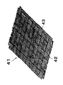
図4は、本発明に用いる強化布帛としての二方向性織物41を示す概略斜視図である。強化繊維糸条42が強化布帛41の長さ方向、つまりたて方向に配列し、よこ方向に強化繊維糸条43が配列し、たて糸42とよこ糸43が交錯し、図4に示す織組織を有する二方向性織物である。
【0057】
一方向シート、一方向性および二方向性織物における好ましい強化繊維目付は50〜800g/m2の範囲内である。より好ましくは100〜800g/m2、更に好ましくは190〜800g/m2の範囲内である。50g/m2未満であると所定のFRPの厚みを得るための積層枚数が増え、成形の作業性が悪く好ましくない。また、800g/m2を超えるとマトリックス樹脂の含浸性が悪くなるので好ましくない。
【0058】
図5は、本発明に用いる強化布帛としてのステッチ布帛51を示す概略斜視図である。ステッチ布帛51の下面から、まず長さ方向イに対して斜め方向に多数本の強化繊維糸条が並行に配列して+α゜層52を構成し、次いで強化布帛の幅方向に多数本の強化繊維糸条が並行に配列して90゜層53を構成し、次いで斜め方向に多数本の強化繊維糸条が並行に配列して−α゜層54を構成し、次いで強化布帛の長さ方向に多数本の強化繊維糸条が並行に配列して0゜層55を構成し、互いに配列方向が異なる4つの層が積層された状態で、ステッチ糸56でこれら4層が縫合一体化されている。縫合一体化にあたってのステッチ糸56が形成する縫い組織としては、例えば単環縫い、1/1のトリコット編みが挙げられる。なお、図5で、あたかも断面形状が楕円で示されている繊維の集合体が1糸条で、この糸条間にステッチ糸56が配列しているかに見えるが、ステッチ糸56は糸条に対してはランダムに挿入され、楕円で示されている繊維の集合体はステッチ糸の拘束によって形成されているのである。
【0059】
ここで、図5に示した多軸ステッチ布帛の強化繊維の構成は+α゜層/90゜層/−α゜層/0゜層の4層構成について説明したが、これに限定するものではない。たとえば0°層/+45°層/0°層/−45°層/90°層/−45°層/0°層/+45°層/0°層のように、0°層が多く含まれるような、0゜、+α゜、−α゜、90゜の4方向を含むものであってもよい。また、0゜、+α゜、−α゜、90゜のいずれかを含むものであってもよい。なお、バイアス角α゜は、ステッチ布帛をFRPの長さ方向に積層し、強化繊維による剪断補強を効果的に行う観点から45゜が好ましい。
【0060】
図6は、本発明に用いる強化布帛としての多軸織物61を示す概略斜視図である。多軸織物61の下面から、まず織物の幅方向に多数本の強化繊維糸条62が並行に配列して90゜層を構成し、次いで織物の長さ方向に多数本の強化繊維糸条63が並行に配列して0゜層を構成し、長さ方向イに対して斜め方向に多数本の強化繊維糸条64が並行に配列して+α゜層を構成し、次いで斜め方向に多数本の強化繊維糸条65が並行に配列して−α゜層を構成し、互いに配列方向が異なる4つの層が、強化繊維糸条が真直ぐな状態で積層され、織物の長さ方向に配列する多数本の結節糸661、662、663・・・が、これら4層の糸条間に挿入されている。この結節糸66は、上面の強化繊維糸条65と下面の強化繊維糸条62と1本交互に交錯し、上面、下面、上面、下面の順で浮き沈みしながら4つの層が織組織で一体化されている。
【0061】
なお、図6に示した多軸織物61の強化繊維の構成は+α゜層/90゜層/−α゜層/0゜層の4層構成について説明したが、これに限定するものではない。たとえば、0°層が多く含まれるような、0゜、+α゜、−α゜、90゜の4方向を含むものであってもよい。なお、バイアス角α゜は、多軸織物61をFRPの長さ方向に積層し、強化繊維による剪断補強を効果的に行う観点から45゜が好ましい。
【0062】
本発明におけるステッチ布帛および多軸織物の各層の強化繊維目付は100〜1000g/m2の範囲内ものが好ましい。より好ましくは100〜800g/m2、更に好ましくは100〜500g/m2の範囲内である。ステッチ糸や結節糸の挿入部には部分的に強化繊維の存在しない箇所ができ、層方向からの樹脂含浸が可能となるので、通常の織物などの強化布帛に比べて比較的高目付の強化布帛としてもマトリックス樹脂の含浸が阻害されることはないが、1000g/m2 を超えるとなると含浸速度が遅くなるので好ましくない。また、100g/m2 未満になると所定の厚みを得るために必要となる強化布帛枚数が多くなり、積層に手間がかかり好ましくない。各層の強化繊維目付より好ましい範囲は、150〜400g/m2の範囲内ものである。
【0063】
なお、上記に説明したステッチ布帛ならびに多軸織物は、その層方向の強化繊維糸条はクリンプすることなく真っ直ぐに配列しているから、FRPにしたとき、強化繊維糸条やマトリックス樹脂に応力集中が働かないため、強度や弾性率の低下が無く、本発明で使用する好ましい強化布帛といえる。
【0064】
本発明に使用する強化繊維糸条は、マルチフイラメント糸であってガラス繊維糸、有機(アラミド、PBO、PVA、PE等)繊維糸、炭素繊維(PAN系、ピッチ系等)糸等である。炭素繊維は比強度および比弾性率に優れ、殆ど吸水しないので、航空機構造材や自動車の強化繊維として好ましく用いられる。なかでも、下記の高靭性炭素繊維糸であると、FRPの衝撃吸収エネルギーが大きくなるので、航空機の1次構造材としても使えるようになる。すなわち、JIS R7601に準拠して測定される引張弾性率E(GPa)が210GPa以上、破壊歪エネルギーW(MJ/m3=106×J/m3)が40MJ以上であると好ましい。より好ましくは、引張弾性率280GPa以上、かつ破壊歪エネルギーが53MJ/m3以上である。引張弾性率Eが210GPa未満の炭素繊維糸を用いると、構造材としてのFRPの撓み量が許容される様にするために、FRPを構造材として用いる場合に板厚を厚くせねばならず、結果的に重くなってしまう。また、破壊歪エネルギーが40MJ/m3未満であると、FRPに衝撃が付与される際、炭素繊維の破壊によって吸収される衝撃エネルギーが小さいので、余剰のエネルギーは層間のマトリックス樹脂層の破壊に費やされ、層間のクラックも大きくなるので好ましくない。また、信頼性にも劣ったFRPとなる。ここで、破壊歪エネルギーとは、JIS R 7601に準拠して測定される引張強度σ(GPa)と、上記したE値とを用いて、式W=σ2 /2Eに基づいて算出される値のことをいう。
【0065】
本発明に使用する炭素繊維糸条の太さは12,000〜24,000フイラメントであるのが好ましい。とくに、これら太い炭素繊維糸条を用いると、炭素繊維が安くなるので安価な強化布帛が得られ好ましい。
【0066】
一方、一層当たりの強化繊維の目付が小さいと、層内の強化繊維糸条と強化繊維糸条の間に隙間ができ、強化繊維体積率Vfが部分的に不均一となり、成形すると強化繊維体積率Vfが大きなところはFRPが厚くなり、また強化繊維体積率Vfが小さなところはFRPが薄くなり、表面が凸凹したFRPとなる。このような場合には、製織寸前やステッチ糸による一体化加工前に、または/および強化布帛加工後に強化繊維糸条をローラの揺動操作やエアー・ジェット噴射で薄く拡げると、強化布帛の全面にわたり強化繊維の体積比が均一となり、表面が平滑なFRPが得られるので好ましい。
【0067】
次に、本発明のFRPについて説明する。本発明のFRPは、上述のプリフォームにマトリックス樹脂が含浸したものである。かかるマトリックス樹脂は必要に応じて固化(硬化または重合)される。かかるマトリックス樹脂の好ましい例としては、例えば、熱硬化性樹脂、RIM用熱可塑性樹脂等が挙げられるが、中でも注入成形に好適であるエポキシ、フェノール、ビニルエステル、不飽和ポリエステル、シアネートエステル、ビスマレイミドおよびベンゾオキサジンから選ばれる少なくとも1種であるのが好ましい。
【0068】
かかるFRPにおける強化繊維体積率Vfは45〜70%の範囲内であると、本発明の課題である力学特性(特にCAI、CHW)、軽量化効果を高く発現できるため好ましい。より好ましくは45〜62%、さらに好ましくは50〜60%の範囲内である。かかるFRPは、予めプリフォームの段階でVPfを制御しておくことにより、Vfを上記範囲に安定して制御でき、品質が安定したFRPを得ることができる。なお、FRPにおける強化繊維体積率Vfとは、次式で求めた値をいう(単位は%)。なお、ここで用いた記号は下記に準ずる。
【0069】
Vf=(W2×100)/(ρ×T2) (%)
W2:FRP1cm2当たりの強化繊維の重量(g/cm2)
ρ:強化繊維の密度(g/cm3)
T2:FRPの厚さ(cm)
また、本発明のFRPは優れた力学特性を有し、かつ軽量であるため、その用途が航空機、自動車、船舶の輸送機器のいずれかにおける一次構造部材、二次構造部材、外装部材または内装部材であることが好ましい。
【0070】
以下、具体的に図面を用いて説明する。
【0071】
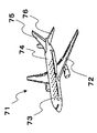
図7は、本発明のFRPを用いた航空機71の概略図である。各種フェアリング、メインランデングギアドア、テイルコーン、エンジンナセルなどの2次構造材以外に、主翼72、床支持桁73、胴体74、垂直尾翼75、水平尾翼76、ウイング・ボックス (図示せず)、 キール(図示せず)等の1次構造材として本発明のプリフォームを成形したFRPを使用すると、優れた特にCAI、CHW等の力学特性、軽量化効果を発現するだけでなく、高い生産性でこれら製造でき、品質が安定しているため、これら航空機の構造部材は本発明のFRPの特に好ましい用途といえる。
【0072】
図8、図9は、本発明の構造要素81、91としての実施例で、従来はスキン材82、92,桁材83、93,リブ材84、94を別々に成形し、これをリベットまたはボルトナット止め、接着剤による接着を施し、組み立てていたが、本発明のFRPおよびその製造方法によれば、スキン材と桁材やリブ材とを一体成形することが可能となり、成形コストを大幅に低減することができる。
【0081】
次に、本発明のFRPの製造法について説明する。
【0082】
本発明のFRPの製造方法は、少なくとも強化繊維糸条によって形成された強化布帛を複数枚積層してなる強化繊維体積率VPfのプリフォームにマトリックス樹脂を注入して強化繊維体積率VfのFRPを成形するFRPの製造方法であって、プリフォーム内の層間に強化布帛以外のガラス転移点が100℃以上の熱可塑性樹脂を主成分とし、熱硬化性樹脂を副成分として、そのガラス転移点が100℃未満の樹脂材料を有し、かつ、強化布帛と樹脂材料とを含む各層が少なくとも部分的に接着しているプリフォームを用い、FRPの強化繊維体積率Vfをプリフォームの強化繊維体積率VPf〜(VPf+10)%の範囲内となるように成形する。より好ましくは(VPf+2)〜(VPf+8)%、更に好ましくは(VPf+3)〜(VPf+6)%の範囲内である。従来は、Vfよりも小さいVPfのプリフォームを成形することによりVfを制御していたが、その高いVPfのためにマトリックス樹脂の含浸性に劣る問題があった。VPfとVfがかかる範囲内になるように成形を行う、すなわちマトリックス樹脂を注入した後に強化繊維を更に密に充填させる(Vfを高める)ことにより、前記問題を解決することが可能となる。一方、所望のVfより10%を越えて低いVPfのプリフォームを用いると、含浸性には優れるものの、所望のVfに成形することが困難となるだけでなく、FRP中のVfの不均一性が大きくなり好ましくない。
【0083】
かかるVPfは45〜62%であり、かつVfは45〜70%の範囲内であるのが好ましい。より好ましくはVPfが50〜58%であり、かつVfが50〜65%の範囲内、更に好ましくはVPfが52〜56%であり、かつVfが55〜60%の範囲内である。なお、VPfやVfは上述の方法で測定したものである。
【0084】
かかるプリフォームは、その層間に強化布帛以外のガラス転移点が100℃以上の熱可塑性樹脂を主成分とし、熱硬化性樹脂を副成分として、ガラス転移点が100℃未満の樹脂材料を有し、かつ強化布帛と樹脂材料とを含む各層が少なくとも部分的に接着していることにより、前述の(イ)〜(ヘ)の効果を発現できる。
【0085】
また、異なる視点からは、本発明のFRPは、本発明のプリフォームを用いて、少なくとも次の工程からなる方法にて製造する。
【0086】
まず、(A)セット工程にて、本発明のプリフォームを成形型に配置する。
【0087】
次いで、(B)注入工程にて、液体化しているマトリックス樹脂を、成形型に注入してプリフォームにマトリックス樹脂を含浸させる。
【0088】
更に、(C)固化工程にて、マトリックス樹脂を固化(硬化または重合)させる。なお、固化させる際、固化効率を上げるために加熱するのが好ましい。必要に応じて、マトリックス樹脂の固化を確実なものにするために、FRPを再度加熱して固化するアフターキュア(二次固化)工程を経てもよい。
【0089】
ここで、上記(A)セット工程において、成形型が雄型および雌型を含む2つから形成されると、マトリックス樹脂の注入時に大気圧以上の圧力をかけることができるため、短サイクルで成形でき、成形コストを低減することが可能となる。
【0090】
また、上記(A)セット工程において、成形型が少なくとも雄型または雌型のいずれかとバック材(例えばフィルム状、型形状を賦形されている柔軟ラバー等)からなり、プリフォームの少なくとも最表面に樹脂拡散媒体を積層し、上記(B)注入工程において、まずマトリックス樹脂を優先的に樹脂拡散媒体(例えばメッシュ、金網等)に注入した後に、プリフォームの厚み方向に含浸させると、成形型費を安くすることができ、成形コストを低減することが可能となる。なお、この場合は樹脂拡散媒体とFRPを成形後に簡単に分離できるようにピールプライ(例えば熱収縮が小さくなる処理を行った熱可塑性繊維によって形成された離型織物等)を樹脂拡散媒体とプリフォームとの間に積層しておくのが好ましい。
【0091】
更に、上記(B)注入工程において、成形型内を真空ポンプ等で脱気して、真空に保ちながらマトリックス樹脂を注入すると、プリフォームへのマトリックス樹脂の含浸が容易となり、より品質の高いFRPを、短サイクルで成形でき、成形コストをより低減することができるため好ましい。
【0092】
また、本発明のFRPは、本発明のプリフォームを用いて少なくとも次の工程からなる方法で製造してもよい。かかる方法でも本発明の課題を解決できる。
【0093】
まず、(D)セット工程にて、上述のプリフォームとマトリックス樹脂とによって形成された樹脂フィルムとを成形型に配置し、成形型(一方が雌型または雄型で、一方がバッグ材であるのが好ましい)内を真空に減圧する。
【0094】
次いで、(E)浸透工程にて、成形型を加熱して樹脂フィルムを溶融させ、プリフォームにマトリックス樹脂を浸透させる。
【0095】
更に、(F)固化工程にて、マトリックス樹脂を固化(硬化または重合)させる。
【0096】
【実施例】
以下、実施例によって更に詳細に説明する。実施例における原材料は次の通りである。
【0097】
強化布帛A:PAN系炭素繊維束[TEX=800、引張弾性率=235GPa、破壊歪エネルギー=52MJ/m3、粘着性付与剤:ポリウレタン樹脂とエポキシ樹脂との混合物を炭素繊維束に対して1重量%]をたて糸(2.4本/cm)とした一方向性織物[補助よこ糸:ガラスヤーン(ECE225 1/0 1Z、バインダータイプDP、日東紡績株式会社製)3本/cm、炭素繊維目付=193g/m2]。
【0098】
強化布帛B:PAN系炭素繊維束[TEX=1030、引張強度5830MPa、引張弾性率294GPa、破壊歪エネルギー58MJ/m3、]をたて糸(1.9本/cm)とした一方向性織物[補助よこ糸および炭素繊維目付は強化布帛Aと同様]。
【0099】
強化布帛C:強化布帛Bに用いたPAN系炭素繊維をたて糸(2.8本/cm)とした一方向性織物[補助よこ糸は強化布帛Aと同様、炭素繊維目付は295g/m2]。
【0100】
樹脂材料A:芯鞘型ポリアミド繊維によって形成された不織布[芯部:ポリアミド6、鞘部:融点110℃の共重合ポリアミド、目付=10g/m2]。
【0101】
樹脂材料B:ポリエーテルスルフォン樹脂(住友化学工業株式会社製スミカエクセル5003Pの微粉砕品)60重量%と、エポキシ樹脂(日本化薬株式会社製AK−601)40重量%とを溶融混練して相溶化させ、粉砕した塊状粒子[レーザー回折・散乱法による平均粒径(D50)が124μm、樹脂材料としてのガラス転移点は68℃の1ピーク]。
【0102】
樹脂材料C:ポリアミド樹脂(株式会社EMS昭和電工製グリルアミドTR55、ガラス転移点=162℃)90重量%とエポキシ樹脂および硬化剤10重量%とをアロイ化(IPN化)した球状粒子(D50=13μm)100重量部を、エポキシ樹脂(ジャパンエポキシレジン株式会社製エピコート1004AF)80重量部とを溶融混練して粉砕した塊状粒子[D50=46μm、樹脂材料としてのガラス転移点は68℃と155℃との2ピーク]。
【0103】
樹脂材料D:エポキシ樹脂[3M Company製PT500]
マトリックス樹脂A:RTM用エポキシ樹脂[東レ株式会社製TR−A31]
マトリックス樹脂B:主液100重量部に硬化液を32重量部加えた液状エポキシ樹脂[70℃におけるE型粘度計による初期粘度が250mPa・s]。
【0104】
主液:Vantico GmbH製”アラルダイト”MY−721を30重量部、ジャパンエポキシレジン株式会社製”エピコート”825を20重量部、日本化薬株式会社製AK−601を20重量部、大日本インキ化学工業株式会社製”エピクロン”HP−7200Lを30重量部、および硬化促進剤としてp−トルエンスルホン酸−n−プロピル1.4重量部が均一になるまで攪拌されたもの。
【0105】
硬化液:ジャパンエポキシレジン株式会社製”エピキュア”Wを18.1重量部、三井化学ファイン株式会社製3,3’−ジアミノジフェニルスルホンを7.2重量部、住友化学工業株式会社製”スミキュア”Sを7.2重量部が均一になるまで撹拌されたもの。
【0106】
本発明のプリフォームおよびそれを成形して得られたFRPに関する評価項目およびその方法は次の通りである。
<プリフォーム(FRP)における強化繊維体積率VPf(Vf)>
プリフォームまたはFRP平板の厚みを測定し、VPf=(WP ×100)/(ρ×TP)またはVf=(Wf×100)/(ρ×Tf)の式に基づき算出した(単位は%)。上式に用いた記号は下記の通り。なお、プリフォームについては、プリフォーム化した後、少なくとも24時間経過したものを測定に供した。
【0107】
WP(Wf):プリフォーム(FRP)における平面方向の1m2から算出されるプリフォーム(FRP)1cm2当たりの強化繊維の重量(g/cm2)
ρ:強化繊維の密度(g/cm3)
TP(Tf):JIS R 7602に基づいた0.1MPaの荷重下で測定したプリフォーム(FRP)の厚さ(cm)
<衝撃後の常温圧縮試験(CAI)>
得られたFRP平板1〜3および5を長152mm×幅102mmに切り出しクーポンを得た。そのクーポンの中心に5.44kg(12ポンド)の錘を0.586mの高さから落下させて6.7kJ/m(1500in・lb/in)の落錘衝撃を与えた後、衝撃後の常温圧縮強度を測定した(負荷速度1.3mm/min)。なお、本測定では4サンプル測定し、それらの平均値をV f で割った値に55を乗じた値(V f =55%換算)を用いた。なお、本試験の詳細は、SACMA SRM 2R−94中に記載がある。
<湿熱処理後の高温圧縮強度(CHW)>
得られたFRP平板4、6からSACMA SRM 1R−94に準拠したクーポンを得た。クーポンを70℃の温水中に14日間浸漬し(湿熱処理)、直ちに高温(82℃)0°圧縮強度を測定した。なお、本測定では5サンプル測定し、それらの平均値をV f で割った値に55を乗じた値(V f =55%換算)を用いた。
【0108】
参考例1
強化布帛Aと樹脂材料Aである不織布とを遠赤外線ヒーターとホットローラーとで加熱して接着し、複合布帛Aを得た。かかる樹脂材料Aは、樹脂材料A自体および強化繊維束に予め付着させておいた粘着性付与剤により接着していた。複合布帛Aを[−45°/0°/+45°/90°]3Sの構成で積層して積層体を得た。この積層体を平面状のプリフォーム型とバッグフィルムとシーラントとにて密閉して真空に減圧した状態で、140℃のオーブンに60分間放置した。その後、オーブンから取り出し、プリフォーム型を室温まで冷却した後に放圧してプリフォーム1を得た。
【0109】
実施例1
樹脂材料Bを強化布帛B上に27g/m2塗布し、遠赤外線ヒーターで加熱して接着し、複合布帛Bを得た。複合布帛Bを参考例1と同様に積層した積層体を得た。この積層体を80℃の平面状のプリフォーム型にてプレス(150kPa、5分間)し、プリフォーム型を室温まで冷却した後に放圧してプリフォーム2を得た。
【0110】
実施例2
樹脂材料Cを強化布帛C上に26g/m2塗布し、遠赤外線ヒーターで加熱して接着し、複合布帛Cを得た。複合布帛Cを[−45/0/+45/90]2Sの構成で積層した積層体を得た。オーブンの温度を130℃にする以外は参考例1と同様にして、この積層体をプリフォーム化してプリフォーム3を得た。
【0111】
実施例3
複合布帛Cを用い、[0]4の構成で積層した以外は実施例2と同様にして、プリフォーム4を得た。
【0112】
以上の参考例1、実施例1〜3で得られたプリフォーム1〜4は、強化布帛同士が樹脂材料により少なくとも部分的に接着され、バラバラにならない強固にバルク化されたものであり、プリフォームとしての取り扱いが可能なものであった。
【0113】
参考例2
得られたプリフォーム1を、40℃のキャビティが平面状の成形金型(雌型)内に配置し、次いで成形金型(雄型)にて型締して−80kPa以下に減圧した。予め準備していたマトリックス樹脂Aを40℃に保ちながら成形金型に、圧力をかけながら注入した。樹脂が含浸した後、80℃に昇温し、12時間放置して硬化させて脱型した。脱型した後、更に180℃にて2時間、フリースタンドでアフターキュアして更に硬化させて、FRP平板1を得た。
【0114】
実施例4
得られたプリフォーム2〜4上に樹脂拡散媒体(アルミ金網)を積層し、平面状の成形金型とバッグ材とでシーラントを用いて密閉することによりキャビティを形成し、80℃のオーブン中に入れる。プリフォームの温度が80℃に達した後に密閉したキャビティを真空に減圧して、マトリックス樹脂Bを80℃に保ちながら大気圧との差圧のみで注入した。樹脂が含浸した後、減圧を続けながら130℃に昇温し、2時間放置して硬化させて脱型した。その後、参考例2と同様にアフターキュアを行って、FRP平板2〜4を得た。
【0115】
比較例1
参考例1で用いた積層体を真空減圧して加熱せずに積層して、そのままをプリフォーム5を得た。
【0116】
比較例2
樹脂材料Cに替えて樹脂材料Dを10g/m2用い、オーブンの温度を100℃にした以外は実施例2と同様にしてプリフォーム6を得た。得られたプリフォーム6を実施例4と同様に成形してFRP平板5を得た。
【0117】
比較例3
樹脂材料Cを用いなかった以外は実施例2と同様にしてプリフォーム7を得た。得られたプリフォーム7を実施例4と同様に成形してFRP平板6を得た。
【0118】
比較例4
樹脂材料Cを用いなかった以外は実施例3と同様にしてプリフォーム8を得た。得られたプリフォーム8を実施例4と同様に成形してFRP平板7を得た。
【0119】
以上の比較例で得られたプリフォーム5、7、8は、強化布帛同士が接着できずにバラバラになり、プリフォーム自体を形成することができなかった。
【0120】
比較例5
プレスによる加圧条件を110℃で500kPa、15分間にした以外は実施例1と同様にしてプリフォーム8を得た。このように得られたプリフォーム8を実施例4と同様に成形したが、VPfが高過ぎ、マトリックス樹脂Bが含浸出来ず、FRP平板を得ることができなかった。
【0121】
評価結果を次の表1に示す。各参考例、実施例、比較例にて用いた材料種類と配合率は表1に示した通りである。
【0122】
【表1】

表1から明らかなように、参考例1、実施例1〜3のプリフォームを成形したFRPは、樹脂材料に熱可塑性樹脂を用いていない比較例2や、樹脂材料そのものを用いていない比較例3のFRPに比して、著しく高いCAIを有した。また、本発明の強化繊維体積率VPf範囲外のプリフォームを成形した比較例4のFRPよりもマトリックス樹脂の含浸性に優れ、かつ強化繊維体積率Vfを高くすることができ、軽量化を達成することができた。なお、参考例1は実施例1、2に比べてCAIに相対的に劣り、実施例1〜3に比べて強化繊維体積率V f を高くすることができなかった。
【0124】
【発明の効果】
本発明のプリフォームによると、注入成形時にマトリックス樹脂の含浸性に優るプリフォーム、および力学特性(特にCAI、CHW)および軽量化効果を高く発現し、品質が安定した(高度にVfが制御された)FRPを高い生産性で(低コストに)製造できる。このようなFRPは、航空機、自動車、船舶等の輸送機器における一次構造部材、二次構造部材、外装部材、内装部材等を始め、特に航空機の一次構造部材に好適である。
【図面の簡単な説明】
【図1】本発明のプリフォームの一態様を説明する概略断面図である。
【図2】本発明のプリフォームの別の一態様を説明する概略断面図である。
【図3】本発明に係る強化布帛としての一方向性織物を示す概略斜視図である。
【図4】本発明に係る強化布帛としての二方向性織物を示す概略斜視図である。
【図5】本発明に係る強化布帛としてのステッチ布帛を示す概略斜視図である。
【図6】本発明に係る強化布帛としての多軸織物を示す概略斜視図である。
【図7】本発明のFRPを使用している航空機の概略斜視図である。
【図8】本発明の構造要素としての実施例を示す概略斜視図である。
【図9】本発明の構造要素としての別の実施例を示す概略斜視図である。
【符号の説明】
11、21:プリフォーム
12、22:強化布帛
13、23:樹脂材料
24:粘着性付与剤
31:一方向性織物
32、42:強化繊維糸条(たて糸)
33:補助糸(よこ糸)
41:二方向性織物
43:強化繊維糸条(よこ糸)
51:ステッチ布帛
52:強化布帛を形成する+α゜の強化繊維層
53:強化布帛を形成する90゜の強化繊維層
54:強化布帛を形成する−α゜の強化繊維層
55:強化布帛を形成する0゜の強化繊維層
56:ステッチ糸
61:多軸織物
62:90゜層の強化繊維糸条
63:0゜層の強化繊維糸条
64:+α゜層の強化繊維糸条
65:−α゜層の強化繊維糸条
66:結節糸
661、662、663・・・:結節糸
71:航空機
72:主翼
73:床支持桁
74:胴体
75:垂直尾翼
76:水平尾翼
81、91:構造要素
82、92:スキン材
83、93:桁材
84、94:リブ材
イ :強化布帛の長さ方向[0001]
BACKGROUND OF THE INVENTION
The present invention relates to a preform used for molding a fiber reinforced plastic (hereinafter referred to as FRP), an FRP comprising the same, andFRPIt relates to the manufacturing method.
[0002]
More specifically, a preform that is excellent in resin impregnation at the time of injection molding of a matrix resin, expresses high mechanical properties and light weight reduction effects, and has a stable quality.FRPIt relates to the manufacturing method.
[0003]
[Prior art]
Recently, the development of subsonic aircraft, etc. has been announced quickly, and civil aircraft is also undergoing major changes. The technical challenges for the materials and structural materials of these innovative aircraft are to satisfy the mechanical characteristics sufficiently, and to achieve epoch-making weight reduction and thorough cost reduction. Thus, there is a need to change materials to primary structural materials that have not used FRP until now. Recently, automobile bodies, doors, chassis, and the like have been moved to FRP in order to reduce the weight, and there is a strong demand for cost reduction over aircraft.
[0004]
Autoclave molding is known as a typical method for producing these FRPs. In autoclave molding, prepregs obtained by impregnating reinforcing fibers with a matrix resin in advance are stacked on a mold having a desired shape, heated and pressurized to form FRP. The prepreg as the intermediate substrate used here is extremely reliable, that is, the reinforcing fiber volume fraction VfHowever, there is an advantage that an FRP having a highly controlled mechanical property is obtained, but there is a problem in that a high cost is required for manufacturing a prepreg and a low productivity of the FRP.
[0005]
On the other hand, injection molding such as a resin transfer molding method (RTM) is an example of a molding method with excellent FRP productivity. In such injection molding, a reinforcing fiber not impregnated with a matrix resin (dry) is placed in a mold, the matrix resin is injected, and the reinforcing fiber is impregnated with the matrix resin to form an FRP.
[0006]
Here, for example, Japanese Patent Publication No. 9-508082 proposes a method of obtaining FRP by using a preform that is compressed to a volume smaller than FRP by applying a thermosetting resin tackifier to a reinforced fabric. ing.
[0007]
However, according to the above proposal, the preform is compressed to a volume smaller than that of the FRP, so that the reinforcing fiber yarns are excessively filled, and there is a problem that the matrix resin impregnation into the preform is extremely inferior at the time of injection molding. On the other hand, if a preform that is too bulky than FRP to improve the impregnation property, the quality of the obtained FRP is not stable, that is, the reinforcing fiber volume fraction VfWas causing problems such as being highly uncontrollable.
[0008]
In addition, according to the above proposal, although the productivity of FRP is excellent, the matrix resin used in the injection molding is limited to a low viscosity, so that the FRP is brittle, and the normal temperature compressive strength after compression (Compression After Impact) , Hereinafter referred to as CAI) etc., there is a problem that is inferior in mechanical properties especially with respect to impact and toughness, and there is a limitation in application to primary structural materials of aircraft in particular, but the problem has been solved It wasn't.
[0009]
Here, the importance of CAI will be described. For example, an aircraft structural material may be subjected to an impact due to a bird collision or a tool falling on the FRP during aircraft assembly / repair. When an impact is applied in the thickness direction of the FRP on which the reinforcing fibers are laminated, the FRP layer is peeled off, cracks are generated, and the impact energy is absorbed. When compressive force acts on such delaminated FRP, there is a phenomenon in which cracks develop and the compressive strength is greatly reduced, and is particularly important for aircraft structural members.
[0010]
In response to this problem of mechanical properties, for example, Japanese Patent Application Laid-Open No. 8-3000039 proposes a method for obtaining FRP having excellent toughness using a plastic having a glass transition point of 100 ° C. or higher. However, according to the above proposal, since the plastic has a high glass transition point and is hard, it is difficult to bond and shape the reinforced fabrics, and it is extremely difficult to form the reinforced fabric. Was.
[0011]
Furthermore, in the above proposals, bi-directional fabrics are used. For example, primary structural members of aircraft have very high mechanical properties (particularly CAI, high temperature compressive strength after wet heat treatment, compression at hot / wet). ) Is required. In bi-directional fabrics, the reinforcing fibers are woven in two directions, so the amount of reinforcing fibers in each direction is essentially halved, and the warp and weft yarns have almost the same fineness. In that respect, the large bending (crimping) of the reinforcing fibers caused only about half the mechanical properties of the prepreg in which the reinforcing fibers were arranged in one direction.
[0012]
In other words, it is excellent in matrix resin impregnation at the time of injection molding, exhibits high mechanical properties such as compressive strength after impact application or after wet heat treatment, and a light weight reduction effect, and can obtain FRP with stable quality and high productivity. Reform and FRP comprising the same have not been obtained, and a technology that satisfies these requirements has been eagerly desired.
[0013]
[Problems to be solved by the invention]
In view of the background of such prior art, the present invention is excellent in resin impregnation at the time of injection molding of a matrix resin, exhibits high mechanical properties such as CAI and CHW and a lightening effect, and has a stable quality (reinforced fiber). It is intended to provide a preform and FRP (with a high volume ratio) andFIt is intended to provide a method for producing RP with high productivity (low cost).
[0014]
[Means for Solving the Problems]
The present invention employs the following means in order to solve such problems. That is, the preform of the present invention is a preform formed by laminating a plurality of reinforcing fabrics formed of at least reinforcing fiber yarns, and the preform other than the reinforcing fabric is provided between layers in the preform.Glass transition point of 100 ° C or higherWith thermoplastic resin as the main componentThe glass transition point is less than 100 ° C. with a thermosetting resin as a subcomponent.Reinforced fiber volume ratio V in the preform having the resin material and the layers including the reinforcing fabric and the resin material adhered to each otherPfIs in the range of 45 to 62%.
[0015]
The FRP of the present invention is an FRP formed of the above preform and a matrix resin, and the preform is impregnated with a matrix resin.
[0021]
Further, the FRP production method of the present invention uses the above-mentioned preform and has a reinforcing fiber volume ratio V formed by laminating a plurality of reinforcing fabrics formed of at least reinforcing fiber yarns.PfReinforced fiber volume fraction V by injecting matrix resin into preformfFRP manufacturing method for molding FRP of FRP, wherein FRP reinforcing fiber volume fraction VfPreform reinforcement fiber volume fraction VPf~ (VPfIt is characterized by being molded so as to be in the range of +10)%.
[0022]
Furthermore, the FRP production method of the present invention is characterized by using the above preform and comprising at least the following steps.
[0023]
(A) A setting step of placing the preform of the present invention in a mold.
[0024]
(B) An injection process in which a liquefied matrix resin is injected into a mold and the preform is impregnated with the matrix resin.
[0025]
(C) Solidification process for solidifying the matrix resin.
[0026]
DETAILED DESCRIPTION OF THE INVENTION
The preform of the present invention will be described. The preform of the present invention is a preform formed by laminating a plurality of reinforcing fabrics formed of at least reinforcing fiber yarns as described above, and the preform other than the reinforcing fabric is provided between layers in the preform.Glass transition point of 100 ° C or higherWith thermoplastic resin as the main componentThe glass transition point is less than 100 ° C. with a thermosetting resin as a subcomponent.Reinforced fiber volume ratio V in the preform having the resin material and the layers including the reinforcing fabric and the resin material adhered to each otherPfIs within the range of 45 to 62%.
[0027]
The present invention will be further described with reference to the drawings.
[0028]
FIG. 1 is a schematic cross-sectional view illustrating one embodiment of the
[0029]
FIG. 2 is a schematic sectional view for explaining another embodiment of the
[0030]
One feature of the preform of the present invention is that a resin material mainly composed of a thermoplastic resin other than a reinforced fabric is provided between layers in the preform. By allowing the resin material to exist between the layers in the preform,
(I) Adhesiveness between reinforced fabrics when obtaining a preform can be imparted.
[0031]
(B) Appropriate stiffness (rigidity) can be imparted to the preform.
[0032]
(C) It is possible to impart a form stabilizing effect such as preventing the misalignment of the reinforcing fabric in the preform.
Thus, the handling property of the preform can be improved. In particular, since the resin material of the present invention is a thermoplastic resin as a main component, compared with the case of using a thermosetting resin as a main component,
(D) The resin material serves as a spacer, and a later-described matrix resin space can be secured between the reinforced fabric layers (giving plastic deformability between the reinforced fabric layers by the matrix resin).
[0033]
(E) The resin material serves as a stopper for cracks generated between the reinforced fabric layers.
Thus, when subjected to an impact, damage between the fabric layers can be suppressed, and particularly excellent mechanical properties (especially CAI) can be achieved.
[0034]
In addition to the above effects,
(F) The resin material serves as a spacer, and the flow path of the matrix resin is ensured between the reinforced fabric layers of the preform, so that not only the matrix resin can be easily impregnated but also the impregnation speed is increased. A new effect such as faster speed and better FRP productivity is also exhibited.
[0035]
Such a resin material only has to be adhered to each layer of the reinforcing fabric and be present at least between the layers in the preform. Even if it exists inside the reinforcing fabric (attached to the reinforcing fiber yarn), it exists on the surface thereof. You may do it. Preferably, 50% by weight or more (more preferably 70% by weight or more) of the reinforcing fabric is unevenly distributed on the surface of the reinforced fabric for the reason described above.
[0036]
Further, another feature of the preform of the present invention is that the reinforcing fiber volume fraction V in the preform is obtained while having such a resin material between layers in the preform.PfIs within the range of 45 to 62%, more preferably within the range of 50 to 58%, and particularly preferably within the range of 52 to 56%.
[0037]
Reinforcing fiber volume fraction VPfIs less than 45%, in particular, in the vacuum injection molding in which the matrix resin is impregnated by the vacuum pressure, the pressure above the atmospheric pressure is not applied to the preform during molding. Rate VPfCannot be controlled within the desired range, and the reinforcing fiber volume fraction V in the obtained FRPfCannot be controlled within the range of 45 to 62%, which is optimal for the mechanical properties. That is, FRP with excellent mechanical properties and high lightening effect and stable quality cannot be obtained. On the other hand, if it exceeds 62%, in the case of injection molding, the reinforcing fibers that are packed too tightly impede the flow of the matrix resin, resulting in poor impregnation and mechanical properties having unimpregnated portions (voids). Only inferior FRP is obtained. Such reinforcing fiber volume fraction VPfIs controlled within the range of 45 to 62%, the reinforcing fiber volume fraction V in the obtained FRPfCan be strictly controlled within a desired range.
[0038]
In the present invention, since the resin material is a thermoplastic resin, the restraint of the reinforcing fiber by the resin material is once released by heating, and the reinforcing fabric, the reinforcing fiber yarn, and then the single fiber of the reinforcing fiber are filled to a desired range. Cooling can be reconstrained at their fill level. By this mechanism, the volume fraction of reinforcing fibers in the preform VPfCan be within the above range.
[0039]
In addition, the reinforcing fiber volume fraction V in the preform referred to in the present invention.PfMeans the value obtained by the following formula (unit:%). The symbols used here are as follows. Here, it is assumed that the preform used for the measurement has undergone at least 24 hours after being formed into a preform, and the springback amount of the preform is substantially saturated.
[0040]
VPf= (W1 × 100) / (ρ × T1) (%)
W1: 1 m in the plane direction in the preform2Preform calculated from 1cm2Weight of reinforcing fiber per g (g / cm2)
ρ: density of reinforcing fiber (g / cm3)
T1: Preform thickness measured in accordance with JIS R 7602 under a load of 0.1 MPa (cm)
The resin material used in the present invention is preferably contained within a range of 1 to 20% by weight with respect to the preform. V Pf From the viewpoint of easily controlling the content within the above range, it is in the range of 1 to 10% by weight, more preferably 2 to 8% by weight, and particularly preferably 3 to 6% by weight. When the resin material is less than 1% by weight, the above effect cannot be exhibited, which is not preferable. When the resin material exceeds 20% by weight, the reinforcing fiber volume fraction V in the preform is Pf Is not preferable because it may be difficult to make the content within the range of 45 to 62%.
[0041]
From another viewpoint, the resin material of the present invention is 2 to 50 g / m.2It is better to be included within the range. Preferably 2 to 20 g / m2, More preferably 4-20 g / m2, Particularly preferably 6 to 15 g / m2It is preferable to adhere to the reinforcing fabric within the range of. 2g / m2If it is less than the range, the effect of improving the mechanical properties (particularly CAI) becomes small, such being undesirable. 50 g / m2If it exceeds 1, the heat resistance, chemical resistance, and CHW of FRP will decrease, which may be undesirable.
[0042]
Next, the preferable form of the resin material used by this invention is demonstrated. As such a resin material, it is possible to use an organic fiber fabric formed by organic fiber yarns, a particle or a film. Any form of the present invention can solve the problems of the present invention. In addition, as the film, a film that can ensure the flow path of the matrix resin in the thickness direction of the preform, such as a perforated film or a porous film, is preferably used.
[0043]
Among these, it is preferable to use an organic fiber fabric from the viewpoint of the handling property as a resin material and the impregnation property of a matrix resin when producing a preform described later. Such organic fiber fabric refers to, for example, nonwoven fabrics, mats, nets, meshes, woven fabrics, knitted fabrics, short fiber groups, and the like that can secure a resin flow path in a direction perpendicular to the lamination of reinforcing fabrics, and combinations thereof. included. Among these, non-woven fabrics, mats or meshes are particularly preferable because they can be obtained at a low cost and the above-described effects are highly exhibited.
[0044]
Also, the reinforcing fiber volume fraction V in the preformPfThe resin material is preferably in the form of particles from the viewpoint of particularly increasing the value. Unlike organic fiber fabrics and films, in the form of particles, not only the amount of resin material can be easily set, but also a thermoplastic resin that is difficult to fabricate or film (or expensive to process) is used. This is preferable. In this case, the average particle diameter is preferably in the range of 1 to 500 μm. From the viewpoint of mechanical properties, it is in the range of 1 to 150 μm, more preferably 5 to 100 μm, and particularly preferably 8 to 50 μm. That is, when the average particle diameter is less than 1 μm, the amount of particles intervening between the layers varies due to the particles entering between the reinforcing fibers. An average particle diameter exceeding 500 μm is not preferable because the number of particles to be dispersed is reduced with respect to a predetermined particle distribution weight, and it becomes difficult to uniformly distribute particles. The average particle diameter is D measured by a laser diffraction / scattering method.50The measurement in the present invention was performed with LMS-24 manufactured by Seishin Enterprise Co., Ltd.
[0045]
Such a resin material is mainly composed of a thermoplastic resin. As such a thermoplastic resin, those having good compatibility with the matrix resin and capable of solving the problems of the present invention can be selected. In particular, in order to express high CHW,Glass transition point of 100 ° C or higherHigh glass transition point (preferablyIs over 150 ℃)AndFor example, use polyamide, polyimide, polyamideimide, polyetherimide, polysulfone, polyethersulfone, polyphenylene ether, polyethernitrile, polyetheretherketone and polyetherketoneketone, their modified resin, copolymer resin, etc. Can do.
[0046]
Among them, a copolymerized polyamide resin is more preferable. Such a copolymerized polyamide resin can achieve a high effect of the present invention at low cost. Examples of such copolymerized polyamide resins include polyamides such as
[0047]
In addition, the resin material has subcomponents other than the thermoplastic resin for further functionalization (particularly adhesion to a reinforced fabric, flexibility of the resin material itself, chemical resistance, water resistance, heat resistance, etc.). be able to. Such subcomponents include:at leastThermosetting resinIs included. In addition,Compounds other than resins such as lubricants, plasticizers, heat stabilizers, etc.May be included.
[0048]
Such a subcomponent itself, or a resin material having a subcomponent, has a low glass transition point when in the form of a preform, and a high glass transition point after being molded into FRP, can be preformed, and Can give excellent mechanical propertiesTheBecause of these requirements, a thermosetting resin is included as an accessory component.It is a waste.The thermoplastic resin that is the main component is coated with the thermosetting resin.TheIf the thermosetting resin is at least partially (preferably entirely) alloyed (preferably an interpenetrating network (IPN)), the chemical interaction with the matrix resin can be controlled, whereby a reinforced fabric In addition to further improving the adhesion and mechanical properties (especially CAI) to the resin, it also has the effect of improving the chemical resistance and heat resistance of the resin material and suppressing water absorption.The
[0049]
That is, the resin material of the present invention has a glass transition point of the main component thermoplastic resin.Over 100 ℃Even if it is high, the glass transition point as a resin material is not 100 ° C due to its subcomponents.Full (Preferably less than 90 ° C, more preferably less than 85 ° C)WhenBecomingAndThus, the problem of the present invention can be easily solved.
[0050]
The preform of the present invention is formed of at least a plurality of reinforcing fabrics and a resin material mainly composed of a thermoplastic resin, and may further contain a tackifier between layers in the preform. When such a tackifier is disposed between the layers or attached to the reinforcing fiber yarn or the reinforcing fabric, not only the bonding between the reinforcing fabrics and the bonding between the reinforcing fabric and the resin material can be performed more efficiently, In particular, when the resin material is particles, it can be reliably bonded to the reinforcing fabric.
[0051]
Such a tackifier may be a thermoplastic resin or a thermosetting resin, but the above-mentioned resin is one having thermoplasticity (including not only the thermoplastic resin but also a thermosetting resin before curing). V in the preform for the same reason as the materialPfIs preferable because it is easy to be within the range of 45 to 62%. Among these, it is preferable to use a thermosetting resin as a main component because the mechanical properties (particularly CHW) of the obtained FRP are expressed as high as possible. Examples of such a thermosetting resin include epoxy, unsaturated polyester, phenol, and the like, and examples of the thermoplastic resin include polyurethane, polyamide, polyester, polyolefin, and the like. Among these, at least one selected from epoxy, polyurethane, and polyamide is preferable. The tackifier may contain a curing agent, a curing accelerator, a catalyst, and the like.
[0052]
Such a tackifier, particularly when attached to a reinforcing fiber yarn, can combine the functions of concentrating reinforcing fibers and imparting tackiness in a preform, and can be handled as a reinforcing fabric, and can be bonded to each reinforcing fabric layer. It is preferable because it can have properties and the like. In this case, it is preferably within the range of 0.4 to 1.5% by weight. More preferably, it is in the range of 0.5 to 1.2% by weight, and still more preferably in the range of 0.6 to 1% by weight. When the tackifier is less than 0.4% by weight, the outermost layer of the bobbin and the reinforcing fibers on the side face become fuzzy when handling the bobbin around which the reinforcing fiber yarn is wound. On the other hand, when the content exceeds 1.5% by weight, a strong film is formed on the surface of the reinforcing fiber yarn, which adversely affects the impregnation of the matrix resin. .
[0053]
Next, the reinforcing fabric formed by at least the reinforcing fiber yarn used in the present invention will be described. Such reinforced fabrics include woven fabrics (unidirectional, bidirectional, multiaxial), knitted fabrics, braids, sheets aligned in one direction (unidirectional sheets), and multi-layers in which two or more unidirectional sheets are stacked. A shaft sheet etc. are mentioned, and these fabrics may be a product in which a plurality of fabrics are integrated by various joining means using resins such as stitch yarns, knot yarns, sackcloths, binders and the like. In particular, when used as a structural (particularly primary structure) member of a transport device (particularly an aircraft), it is preferably a unidirectional sheet, a unidirectional fabric, or a multiaxial sheet (particularly stitched).
[0054]
FIG. 3 is a schematic perspective view showing a
[0055]
From another perspective, as a resin materialGlass transition point of 100 ° C or higherThermoplastic resinWith a glass transition point of less than 100 ° C.It is also one of the preferred embodiments of the present invention to use the auxiliary yarn formed by the above. The resin material of the present invention has such a thermoplastic resin.Containing main component and thermosetting resin as subcomponentEven if the auxiliary yarn is formed by, the effect is exhibited. The above-mentioned auxiliary yarn is processed such as covering, blending, and interweaving.Good.
[0056]
FIG. 4 is a schematic perspective view showing a
[0057]
Preferred reinforcing fiber basis weight in unidirectional sheets, unidirectional and bi-directional fabrics is 50 to 800 g / m2Is within the range. More preferably 100 to 800 g / m2More preferably, 190 to 800 g / m2Is within the range. 50 g / m2If it is less than the range, the number of laminated layers for obtaining a predetermined FRP thickness increases, and the workability of molding is not preferable. 800g / m2If it exceeds 1, the impregnation property of the matrix resin is deteriorated.
[0058]
FIG. 5 is a schematic perspective view showing a
[0059]
Here, the configuration of the reinforcing fibers of the multiaxial stitched fabric shown in FIG. 5 has been described as a four-layer configuration of + α ° layer / 90 ° layer / −α ° layer / 0 ° layer, but is not limited thereto. . For example, a lot of 0 ° layers are included such as 0 ° layer / + 45 ° layer / 0 ° layer / −45 ° layer / 90 ° layer / −45 ° layer / 0 ° layer / + 45 ° layer / 0 ° layer. It may include four directions of 0 °, + α °, −α °, and 90 °. Further, it may include any of 0 °, + α °, −α °, and 90 °. The bias angle α ° is preferably 45 ° from the viewpoint that the stitch fabric is laminated in the length direction of the FRP and the shear reinforcement by the reinforcing fibers is effectively performed.
[0060]
FIG. 6 is a schematic perspective view showing a
[0061]
In addition, although the structure of the reinforcing fiber of the
[0062]
The reinforcing fiber basis weight of each layer of the stitched fabric and the multiaxial woven fabric in the present invention is 100 to 1000 g / m.2Those within the range are preferred. More preferably 100 to 800 g / m2More preferably, it is 100-500 g / m2Is within the range. Reinforcement with a relatively high basis weight compared to reinforced fabrics such as ordinary woven fabrics is possible because there is a part where the reinforcing fibers do not exist partially in the insertion part of the stitch yarn and knot yarn, and resin impregnation from the layer direction is possible. Even as a fabric, impregnation of the matrix resin is not hindered, but 1000 g / m2Exceeding this is not preferable because the impregnation rate becomes slow. Moreover, 100 g / m2If it is less than the range, the number of reinforced fabrics required to obtain a predetermined thickness increases, which is not preferable because it takes time and labor for lamination. A more preferable range of the reinforcing fiber basis weight of each layer is 150 to 400 g / m.2It is within the range.
[0063]
In the stitch fabric and multiaxial fabric described above, the reinforcing fiber yarns in the layer direction are arranged straight without crimping. Therefore, when FRP is used, stress concentration is applied to the reinforcing fiber yarns and the matrix resin. Does not work, there is no decrease in strength and elastic modulus, which can be said to be a preferred reinforced fabric used in the present invention.
[0064]
The reinforcing fiber yarns used in the present invention are multifilament yarns such as glass fiber yarns, organic (aramid, PBO, PVA, PE, etc.) fiber yarns, carbon fiber (PAN type, pitch type, etc.) yarns and the like. Since carbon fiber is excellent in specific strength and specific elastic modulus and hardly absorbs water, it is preferably used as a reinforcing fiber for aircraft structural materials and automobiles. Among them, the following high-toughness carbon fiber yarns can be used as a primary structural material for aircraft since the shock absorption energy of FRP increases. That is, the tensile elastic modulus E (GPa) measured in accordance with JIS R7601 is 210 GPa or more, the fracture strain energy W (MJ / mThree= 106× J / mThree) Is preferably 40 MJ or more. More preferably, the tensile elastic modulus is 280 GPa or more and the fracture strain energy is 53 MJ / m.ThreeThat's it. When a carbon fiber yarn having a tensile elastic modulus E of less than 210 GPa is used, the thickness of the plate must be increased when FRP is used as a structural material in order to allow the amount of deflection of the FRP as a structural material. As a result, it becomes heavy. In addition, the fracture strain energy is 40 MJ / mThreeIf it is less than that, the impact energy absorbed by the destruction of the carbon fiber is small when an impact is applied to the FRP, so the surplus energy is expended in the destruction of the matrix resin layer between the layers, and the cracks between the layers also increase. Therefore, it is not preferable. Further, the FRP is inferior in reliability. Here, the fracture strain energy refers to the formula W = σ using the tensile strength σ (GPa) measured in accordance with JIS R 7601 and the E value described above.2 A value calculated based on / 2E.
[0065]
The thickness of the carbon fiber yarn used in the present invention is preferably 12,000 to 24,000 filaments. In particular, the use of these thick carbon fiber yarns is preferable because carbon fibers can be made cheap and an inexpensive reinforced fabric can be obtained.
[0066]
On the other hand, when the basis weight of the reinforcing fiber per layer is small, a gap is formed between the reinforcing fiber yarn and the reinforcing fiber yarn in the layer, and the reinforcing fiber volume ratio VfIs partially non-uniform, and when molded, reinforcing fiber volume fraction VfIs larger, FRP becomes thicker, and reinforcing fiber volume fraction VfIs small, the FRP becomes thin, and the surface becomes uneven. In such a case, if the reinforcing fiber yarn is thinly spread by swinging operation of the roller or air jet before weaving or before the integration processing with the stitch yarn and / or after the processing of the reinforcing fabric, the entire surface of the reinforcing fabric is obtained. This is preferable because the volume ratio of the reinforcing fibers becomes uniform and FRP having a smooth surface can be obtained.
[0067]
Next, the FRP of the present invention will be described. The FRP of the present invention is obtained by impregnating the above-mentioned preform with a matrix resin. Such a matrix resin is solidified (cured or polymerized) as necessary. Preferable examples of such matrix resins include, for example, thermosetting resins, RIM thermoplastic resins and the like, among which epoxy, phenol, vinyl ester, unsaturated polyester, cyanate ester, bismaleimide are suitable for injection molding. And at least one selected from benzoxazine.
[0068]
Reinforcing fiber volume fraction V in such FRPfIs preferably in the range of 45 to 70%, since the mechanical properties (particularly CAI, CHW) and the weight reduction effect that are the subject of the present invention can be expressed highly. More preferably, it is 45 to 62%, and further preferably 50 to 60%. Such FRP is preliminarily processed at the preform stage.PfBy controlling VfCan be stably controlled within the above range, and an FRP with stable quality can be obtained. Reinforcing fiber volume fraction V in FRPfMeans the value obtained by the following formula (unit:%). The symbols used here are as follows.
[0069]
Vf= (W2 × 100) / (ρ × T2) (%)
W2: FRP 1cm2Weight of reinforcing fiber per g (g / cm2)
ρ: density of reinforcing fiber (g / cmThree)
T2: FRP thickness (cm)
In addition, since the FRP of the present invention has excellent mechanical properties and is lightweight, the use thereof is a primary structural member, a secondary structural member, an exterior member, or an interior member in any of aircraft, automobiles, and ship transportation equipment. It is preferable that
[0070]
Hereinafter, it demonstrates concretely using drawing.
[0071]
FIG. 7 is a schematic view of an
[0072]
FIG. 8 and FIG. 9 are embodiments as the
[0081]
Next, the manufacturing method of FRP of this invention is demonstrated.
[0082]
In the method for producing FRP of the present invention, a matrix resin is injected into a preform having a reinforcing fiber volume ratio VPf formed by laminating a plurality of reinforcing fabrics formed of at least reinforcing fiber yarns, and an FRP having a reinforcing fiber volume ratio Vf is obtained. A method of manufacturing FRP to be molded,A thermoplastic resin having a glass transition point other than the reinforced fabric other than the reinforced fabric as a main component, a thermosetting resin as a subcomponent, and a resin material having a glass transition point of less than 100 ° C. between the layers in the preform, And using the preform in which each layer containing the reinforcing fabric and the resin material is at least partially bonded,The FRP reinforcing fiber volume fraction Vf is molded so as to fall within the range of the preform reinforcing fiber volume fraction VPf to (VPf + 10)%. More preferably, it is in the range of (VPf + 2) to (VPf + 8)%, more preferably (VPf + 3) to (VPf + 6)%. Conventionally, Vf is controlled by molding a preform of VPf smaller than Vf. However, the high VPf has a problem that the impregnation property of the matrix resin is inferior. Molding is performed so that VPf and Vf are within such a range, that is, by filling the reinforcing fibers more densely after injecting the matrix resin (increasing Vf), the above problem can be solved. On the other hand, if a preform with a VPf lower than 10% lower than the desired Vf is used, the impregnation property is excellent, but not only it becomes difficult to form the desired Vf but also the nonuniformity of Vf in the FRP. Is unfavorable because it increases.
[0083]
VPfIs 45-62% and VfIs preferably in the range of 45 to 70%. More preferably VPfIs 50-58% and VfIs in the range of 50-65%, more preferably VPfIs 52 to 56%, and VfIs in the range of 55-60%. VPfOr VfIs measured by the method described above.
[0084]
Such a preform has a layer other than a reinforced fabric between its layers.Glass transition point of 100 ° C or higherWith thermoplastic resin as the main componentThe glass transition point is less than 100 ° C. with a thermosetting resin as a subcomponent.Each layer having a resin material and including the reinforcing fabric and the resin material is at least partially bonded.ByThe effects (a) to (f) described above can be exhibited.The
[0085]
From a different point of view, the FRP of the present invention is produced by a method comprising at least the following steps using the preform of the present invention.
[0086]
First, (A) In the setting step, the preform of the present invention is placed in a mold.
[0087]
Then (B) In the injection step, the liquefied matrix resin is injected into a mold and the preform is impregnated with the matrix resin.
[0088]
In addition, (C) In the solidification step, the matrix resin is solidified (cured or polymerized). In addition, when solidifying, it is preferable to heat to increase the solidification efficiency. If necessary, in order to ensure the solidification of the matrix resin, an after-curing (secondary solidification) step in which the FRP is solidified by heating again may be performed.
[0089]
Where (A) In the setting process, if the mold is formed from two molds including male mold and female mold, pressure higher than atmospheric pressure can be applied when the matrix resin is injected, so molding can be done in a short cycle and the molding cost is reduced. It becomes possible to do.
[0090]
In addition, (A) In the setting step, the mold is composed of at least a male mold or a female mold and a backing material (for example, a flexible rubber having a shape of a film or mold), and a resin diffusion medium is provided on at least the outermost surface of the preform. Laminate and above (B) In the injection step, first, the matrix resin is preferentially injected into the resin diffusion medium (for example, mesh, wire mesh, etc.) and then impregnated in the thickness direction of the preform, so that the mold cost can be reduced and the molding cost can be reduced. It becomes possible to reduce. In this case, a peel ply (for example, a release woven fabric formed of thermoplastic fibers subjected to a process that reduces thermal shrinkage) is used as a resin diffusion medium and a preform so that the resin diffusion medium and FRP can be easily separated after molding. It is preferable to laminate between the two.
[0091]
Furthermore, the above (B) In the injection process, the mold is evacuated with a vacuum pump or the like, and the matrix resin is injected while keeping the vacuum, so that the preform can be easily impregnated with the matrix resin, and a higher quality FRP can be obtained in a short cycle. It is preferable because it can be molded and the molding cost can be further reduced.
[0092]
The FRP of the present invention may be produced by a method comprising at least the following steps using the preform of the present invention. Such a method can also solve the problems of the present invention.
[0093]
First, (D) In the setting step, a resin film formed by the above-described preform and matrix resin is placed in a mold, and the mold (one is preferably a female or male mold and one is a bag material) The inside is reduced to vacuum.
[0094]
Then (E) In the infiltration step, the mold is heated to melt the resin film, and the matrix resin is infiltrated into the preform.
[0095]
In addition, (F) In the solidification step, the matrix resin is solidified (cured or polymerized).
[0096]
【Example】
Hereinafter, it demonstrates still in detail according to an Example. The raw materials in the examples are as follows.
[0097]
Reinforced fabric A: PAN-based carbon fiber bundle [TEX = 800, tensile modulus = 235 GPa, fracture strain energy = 52 MJ / mThree, Tackifier: Unidirectional woven fabric [auxiliary weft yarn: glass yarn (ECE225 1) with a mixture of polyurethane resin and epoxy resin 1% by weight with respect to the carbon fiber bundle] warp yarn (2.4 yarns / cm) / 0 1Z, binder type DP, manufactured by Nittobo Co., Ltd.) 3 / cm, carbon fiber basis weight = 193 g / m2].
[0098]
Reinforced fabric B: PAN-based carbon fiber bundle [TEX = 1030, tensile strength 5830 MPa, tensile elastic modulus 294 GPa, fracture strain energy 58 MJ / mThree,] Is a unidirectional woven fabric with warp yarn (1.9 pieces / cm) [auxiliary weft yarn and carbon fiber basis weight are the same as those of the reinforcing fabric A].
[0099]
Reinforced fabric C: unidirectional woven fabric using PAN-based carbon fiber used for reinforced fabric B as warp yarn (2.8 yarns / cm) [Auxiliary weft yarn is the same as reinforced fabric A, and the carbon fiber basis weight is 295 g / m.2].
[0100]
Resin material A: Non-woven fabric formed of core-sheath type polyamide fiber [core: polyamide 6, sheath: copolymer polyamide having a melting point of 110 ° C., basis weight = 10 g / m2].
[0101]
Resin material B: 60% by weight of polyethersulfone resin (Sumitomo Chemical Co., Ltd. Sumika Excel 5003P finely pulverized product) and 40% by weight of epoxy resin (Nippon Kayaku Co., Ltd. AK-601) were melt-kneaded. Compatibilized and crushed massive particles [average particle diameter by laser diffraction / scattering method (D50) Is 124 μm, and the glass transition point as a resin material is one peak at 68 ° C.].
[0102]
Resin material C: Spherical particles (IPN) of 90% by weight of polyamide resin (manufactured by EMS Showa Denko Co., Ltd. Grillamide TR55, glass transition point = 162 ° C.) and 10% by weight of epoxy resin and hardener (D)50= 13 μm) lump particles obtained by melting and kneading 100 parts by weight of 80 parts by weight of epoxy resin (Epicoat 1004AF manufactured by Japan Epoxy Resin Co., Ltd.) [D50= 46 μm, the glass transition point as a resin material is two peaks of 68 ° C. and 155 ° C.].
[0103]
Resin material D: Epoxy resin [PT500 made by 3M Company]
Matrix resin A: Epoxy resin for RTM [TR-A31 manufactured by Toray Industries, Inc.]
Matrix resin B: A liquid epoxy resin obtained by adding 32 parts by weight of a hardening liquid to 100 parts by weight of a main liquid [initial viscosity at 70 ° C. by an E-type viscometer is 250 mPa · s].
[0104]
Main liquid: 30 parts by weight of “Araldite” MY-721 manufactured by Vantico GmbH, 20 parts by weight of “Epicoat” 825 manufactured by Japan Epoxy Resin Co., Ltd., 20 parts by weight of AK-601 manufactured by Nippon Kayaku Co., Ltd., Dainippon Ink & Chemicals, Inc. Stirred until 30 parts by weight of “Epiclon” HP-7200L manufactured by Kogyo Co., Ltd. and 1.4 parts by weight of p-toluenesulfonic acid-n-propyl as a curing accelerator were uniform.
[0105]
Curing solution: 18.1 parts by weight of “Epicure” W manufactured by Japan Epoxy Resin Co., Ltd., 7.2 parts by weight of 3,3′-diaminodiphenylsulfone manufactured by Mitsui Chemicals Fine Co., Ltd., “SumiCure” manufactured by Sumitomo Chemical Co., Ltd. Stirred until 7.2 parts by weight of S was uniform.
[0106]
Evaluation items and methods regarding the preform of the present invention and the FRP obtained by molding the preform are as follows.
<Reinforced fiber volume fraction V in preform (FRP)Pf(Vf)>
Measure the thickness of the preform or FRP flat platePf=(WP × 100)/ (Ρ × TP) Or Vf= (Wf× 100) / (ρ × Tf) Based on the formula (unit:%). The symbols used in the above formula are as follows. In addition, about the preform, after making into a preform, what passed for at least 24 hours was used for the measurement.
[0107]
WP(Wf): 1 m in the plane direction in the preform (FRP)2Preform (FRP) calculated from 1cm2Weight of reinforcing fiber per g (g / cm2)
ρ: density of reinforcing fiber (g / cm3)
TP(Tf): Thickness (cm) of the preform (FRP) measured under a load of 0.1 MPa based on JIS R 7602
<Room temperature compression test after impact (CAI)>
The obtained FRP flat plates 1 to 3 and 5 were cut into a length of 152 mm and a width of 102 mm to obtain a coupon. A 4.44 kg (12 lb) weight is dropped from the height of 0.586 m to the center of the coupon, and a drop weight impact of 6.7 kJ / m (1500 in · lb / in) is applied. The compressive strength was measured (load speed 1.3 mm / min). In this measurement, 4 samples were measured, and the average value was measured as V f The value divided by 55 multiplied by 55 (V f = 55% conversion) was used. For details of this test, see SACMA. SRM There is a description in 2R-94.
<High temperature compressive strength after wet heat treatment (CHW)>
SACMA from the obtained FRP flat plates 4 and 6 SRM A coupon based on 1R-94 was obtained. The coupon was immersed in warm water at 70 ° C. for 14 days (wet heat treatment), and immediately measured at 0 ° compressive strength at high temperature (82 ° C.). In this measurement, 5 samples are measured, and the average value of these is V f The value divided by 55 multiplied by 55 (V f = 55% conversion) was used.
[0108]
referenceExample 1
The reinforced fabric A and the nonwoven fabric which is the resin material A were heated and bonded with a far-infrared heater and a hot roller to obtain a composite fabric A. The resin material A was adhered by the tackifier that was previously attached to the resin material A itself and the reinforcing fiber bundle. Composite fabric A [-45 ° / 0 ° / + 45 ° / 90 °]3SThe laminated body was obtained by laminating with the structure This laminate was sealed with a planar preform mold, a bag film, and a sealant and left in an oven at 140 ° C. for 60 minutes in a state where the pressure was reduced to a vacuum. Thereafter, the preform 1 was taken out from the oven, cooled to room temperature, and then released to obtain a preform 1.
[0109]
Example1
Resin material B on reinforced fabric B 27 g / m2It was applied and heated with a far infrared heater and bonded to obtain a composite fabric B. Composite fabric BreferenceThe laminated body laminated | stacked similarly to Example 1 was obtained. This laminate was pressed with a planar preform mold at 80 ° C. (150 kPa, 5 minutes), and after cooling the preform mold to room temperature, the pressure was released to obtain a preform 2.
[0110]
Example2
26 g / m of resin material C on reinforced fabric C2The composite fabric C was obtained by coating and heating with a far-infrared heater and bonding. Composite fabric C [-45 / 0 / + 45/90]2SThe laminated body laminated | stacked by the structure of was obtained. Except to set the oven temperature to 130 ° CreferenceIn the same manner as in Example 1, this laminate was preformed to obtain Preform 3.
[0111]
Example3
Using composite fabric C, [0]FourExample with the exception of stacking2In the same manner, Preform 4 was obtained.
[0112]
More thanreferenceExample 1Examples 1-3The preforms 1 to 4 obtained in the above were reinforced fabrics that were at least partially bonded to each other by a resin material, and were firmly bulked so as not to fall apart, and could be handled as preforms. .
[0113]
referenceExample2
The obtained preform 1 was placed in a molding die (female) having a flat cavity at 40 ° C., and then clamped by the molding die (male) to reduce the pressure to −80 kPa or less. The matrix resin A prepared in advance was poured into the molding die while maintaining pressure at 40 ° C. while applying pressure. After the impregnation with the resin, the temperature was raised to 80 ° C. and left to cure for 12 hours to remove the mold. After demolding, it was further cured at 180 ° C. for 2 hours with a free stand and further cured to obtain an FRP flat plate 1.
[0114]
Example4
On the obtained preforms 2-4TreeA fat diffusion medium (aluminum wire mesh) is laminated, and a cavity is formed by sealing with a flat molding die and a bag material using a sealant, and placed in an oven at 80 ° C. After the temperature of the preform reached 80 ° C., the sealed cavity was decompressed to a vacuum, and the matrix resin B was injected only at a pressure difference from the atmospheric pressure while maintaining the matrix resin B at 80 ° C. After the resin was impregnated, the temperature was raised to 130 ° C. while continuing to reduce the pressure, and the mixture was left for 2 hours to be cured and demolded. afterwards,referenceExample2After-curing was performed in the same manner as above to obtain FRP flat plates 2 to 4.
[0115]
Comparative Example 1
referenceThe laminate used in Example 1 was laminated without heating under vacuum and heating, and a preform 5 was obtained as it was.
[0116]
Comparative Example 2
10 g / m of resin material D instead of resin material C2Example, except that the oven temperature was 100 ° C2In the same manner, Preform 6 was obtained. Examples of the obtained preform 64The FRP flat plate 5 was obtained by molding in the same manner as described above.
[0117]
Comparative Example 3
Example except that resin material C was not used2In the same manner, Preform 7 was obtained. Example of preform 7 obtained4The FRP flat plate 6 was obtained by molding in the same manner as above.
[0118]
Comparative Example 4
Example except that resin material C was not used3In the same manner, Preform 8 was obtained. Example of preform 8 obtained4FRP flat plate 7 was obtained by molding in the same manner as above.
[0119]
Preforms 5, 7, and 8 obtained in the above comparative examples were not able to bond the reinforcing fabrics, but fell apart, and the preform itself could not be formed.
[0120]
Comparative Example 5
Example except that pressurizing condition at 110 ° C. is 500 kPa for 15 minutes.1In the same manner, Preform 8 was obtained. The preform 8 thus obtained was used as an example.4Molded in the same way as VPfWas too high, the matrix resin B could not be impregnated, and an FRP flat plate could not be obtained.
[0121]
The evaluation results are shown in Table 1 below. eachReference examples,The material types and blending ratios used in Examples and Comparative Examples are as shown in Table 1.
[0122]
[Table 1]
As is clear from Table 1,referenceExample 1,Example 13The FRP formed with the preform had a significantly higher CAI than the FRP of Comparative Example 2 in which a thermoplastic resin was not used as the resin material and Comparative Example 3 in which the resin material itself was not used. The reinforcing fiber volume fraction V of the present inventionPfThe impregnation of the matrix resin is superior to the FRP of Comparative Example 4 in which a preform outside the range is molded, and the reinforcing fiber volume fraction VfThe weight can be increased and the weight can be reduced.In addition, Reference Example 1 is relatively inferior to CAI compared to Examples 1 and 2, and reinforcing fiber volume fraction V compared to Examples 1 to 3. f Could not be raised.
[0124]
【The invention's effect】
According to the preform of the present invention, the preform excellent in the impregnation property of the matrix resin at the time of injection molding, the mechanical properties (especially CAI, CHW) and the lightening effect are highly expressed, and the quality is stable (highly VfFRP can be manufactured with high productivity (low cost). Such FRP is particularly suitable for primary structural members of aircraft, including primary structural members, secondary structural members, exterior members, interior members, and the like in transportation equipment such as aircraft, automobiles, and ships.
[Brief description of the drawings]
FIG. 1 is a schematic cross-sectional view illustrating one embodiment of a preform of the present invention.
FIG. 2 is a schematic sectional view for explaining another embodiment of the preform of the present invention.
FIG. 3 is a schematic perspective view showing a unidirectional fabric as a reinforcing fabric according to the present invention.
FIG. 4 is a schematic perspective view showing a bidirectional fabric as a reinforcing fabric according to the present invention.
FIG. 5 is a schematic perspective view showing a stitch fabric as a reinforcing fabric according to the present invention.
FIG. 6 is a schematic perspective view showing a multiaxial woven fabric as a reinforced fabric according to the present invention.
FIG. 7 is a schematic perspective view of an aircraft using the FRP of the present invention.
FIG. 8 is a schematic perspective view showing an embodiment as a structural element of the present invention.
FIG. 9 is a schematic perspective view showing another embodiment as a structural element of the present invention.
[Explanation of symbols]
11, 21: Preform
12, 22: Reinforced fabric
13, 23: Resin material
24: Tackifier
31: Unidirectional fabric
32, 42: Reinforcing fiber yarn (warp yarn)
33: Auxiliary thread (weft thread)
41: Bidirectional fabric
43: Reinforcing fiber yarn (weft)
51: Stitched fabric
52: + α ° reinforcing fiber layer forming a reinforcing fabric
53: 90 ° reinforcing fiber layer forming reinforcing fabric
54: -α ° reinforced fiber layer forming reinforced fabric
55: 0 ° reinforcing fiber layer forming a reinforcing fabric
56: Stitch yarn
61: Multiaxial fabric
62: 90 ° layer of reinforcing fiber yarn
63: 0 ° reinforcing fiber yarn
64: + α ° layer of reinforcing fiber yarn
65: -α ° layer reinforcing fiber yarn
66: Knot yarn
66166266Three...: Knot yarn
71: Aircraft
72: Main wing
73: Floor support girder
74: Torso
75: Vertical tail
76: Horizontal tail
81, 91: Structural elements
82, 92: Skin material
83, 93: Girder
84, 94: Rib material
B: Length direction of reinforced fabric
Claims (20)
(A)プリフォームを成形型に配置するセット工程。
(B)液体化しているマトリックス樹脂を、成形型に注入してプリフォームにマトリックス樹脂を含浸させる注入工程。
(C)マトリックス樹脂を固化させる固化工程。The FRP according to any one of claims 12 to 15 is produced through at least the following steps ( A ) to ( C ) using the preform according to any one of claims 1 to 11. Manufacturing method.
( A ) The setting process which arrange | positions a preform to a shaping | molding die.
( B ) An injection step of injecting a liquefied matrix resin into a mold and impregnating the preform with the matrix resin.
( C ) A solidification step for solidifying the matrix resin.
Priority Applications (1)
| Application Number | Priority Date | Filing Date | Title |
|---|---|---|---|
| JP2002196838A JP4126978B2 (en) | 2001-07-06 | 2002-07-05 | Preform, FRP comprising the same, and method for producing FRP |
Applications Claiming Priority (3)
| Application Number | Priority Date | Filing Date | Title |
|---|---|---|---|
| JP2001206074 | 2001-07-06 | ||
| JP2001-206074 | 2001-07-06 | ||
| JP2002196838A JP4126978B2 (en) | 2001-07-06 | 2002-07-05 | Preform, FRP comprising the same, and method for producing FRP |
Related Child Applications (1)
| Application Number | Title | Priority Date | Filing Date |
|---|---|---|---|
| JP2008089950A Division JP4609513B2 (en) | 2001-07-06 | 2008-03-31 | Preform manufacturing method |
Publications (3)
| Publication Number | Publication Date |
|---|---|
| JP2003080607A JP2003080607A (en) | 2003-03-19 |
| JP2003080607A5 JP2003080607A5 (en) | 2005-09-22 |
| JP4126978B2 true JP4126978B2 (en) | 2008-07-30 |
Family
ID=26618274
Family Applications (1)
| Application Number | Title | Priority Date | Filing Date |
|---|---|---|---|
| JP2002196838A Expired - Fee Related JP4126978B2 (en) | 2001-07-06 | 2002-07-05 | Preform, FRP comprising the same, and method for producing FRP |
Country Status (1)
| Country | Link |
|---|---|
| JP (1) | JP4126978B2 (en) |
Families Citing this family (56)
| Publication number | Priority date | Publication date | Assignee | Title |
|---|---|---|---|---|
| JP4168734B2 (en) * | 2002-11-15 | 2008-10-22 | 東レ株式会社 | Preform substrate, preform and method for molding fiber reinforced plastic |
| US20080289743A1 (en) * | 2003-05-02 | 2008-11-27 | Tsotsis Thomas K | Highly porous interlayers to toughen liquid-molded fabric-based composites |
| JP4576895B2 (en) * | 2003-06-16 | 2010-11-10 | 東レ株式会社 | Reinforced fiber base material for fiber reinforced composite material and fiber reinforced composite material |
| JP4341419B2 (en) * | 2004-02-03 | 2009-10-07 | 東レ株式会社 | Preform manufacturing method and composite material manufacturing method |
| JP2005272526A (en) * | 2004-03-23 | 2005-10-06 | Toray Ind Inc | Composite material and manufacturing method of the same |
| US20070149080A1 (en) * | 2004-03-30 | 2007-06-28 | Nobuo Asahara | Preform, frp, and processes for producing these |
| JP2005313455A (en) * | 2004-04-28 | 2005-11-10 | Toho Tenax Co Ltd | Multi-axis fabric, its production method, preform material, and fiber-reinfoced plastic molding |
| JP2005349826A (en) * | 2004-05-14 | 2005-12-22 | Toray Ind Inc | Fiber reinforced composite material member |
| JP4576942B2 (en) * | 2004-09-10 | 2010-11-10 | 東レ株式会社 | Preform manufacturing method and preform manufacturing apparatus |
| JP4821262B2 (en) * | 2004-10-22 | 2011-11-24 | 東レ株式会社 | Reinforcing fiber laminate, preform, FRP, reinforcing fiber laminate manufacturing method and manufacturing apparatus thereof |
| JP4670313B2 (en) * | 2004-10-29 | 2011-04-13 | 東レ株式会社 | Method for shaping reinforcing fiber base material for FRP molding |
| JP4631395B2 (en) * | 2004-10-29 | 2011-02-16 | 東レ株式会社 | Method for shaping reinforcing fiber base material for FRP molding |
| US8257823B2 (en) | 2004-12-06 | 2012-09-04 | Toray Industries, Inc. | Molding precursor, process for producing molded fiber-reinforced resin, and molded fiber-reinforced resin |
| JP4817651B2 (en) * | 2004-12-15 | 2011-11-16 | 東邦テナックス株式会社 | Preform substrate for FRP and method for producing preform |
| JP2006306057A (en) * | 2005-03-28 | 2006-11-09 | Toray Ind Inc | Manufacturing method of frp structure |
| JP4759303B2 (en) * | 2005-04-06 | 2011-08-31 | 帝人テクノプロダクツ株式会社 | Composite material using multiaxial fabric |
| AU2006244242B2 (en) * | 2005-05-09 | 2012-07-19 | Cytec Technology Corp. | Resin-soluble thermoplastic veil for composite materials |
| JP5034176B2 (en) * | 2005-05-24 | 2012-09-26 | 東レ株式会社 | Preform binder composition, preform reinforcing fiber substrate, preform manufacturing method, and fiber reinforced composite material manufacturing method |
| JP4769044B2 (en) * | 2005-08-10 | 2011-09-07 | 積水化学工業株式会社 | Vacuum injection molding method for fiber reinforced resin molded products |
| JP5044916B2 (en) * | 2005-09-29 | 2012-10-10 | 東レ株式会社 | Method for producing carbon fiber reinforced plastic with integrated radio wave absorber |
| EP1945430A4 (en) * | 2005-10-11 | 2011-06-29 | Cooperative Res Ct For Advanced Composite Structures Ltd | A method of binding dry reinforcement fibres |
| JP5029072B2 (en) * | 2006-03-15 | 2012-09-19 | 東レ株式会社 | Reinforced fiber substrate laminate and method for producing the same |
| GB201008884D0 (en) * | 2010-05-27 | 2010-07-14 | Hexcel Composites Ltd | Improvements in composite materials |
| JP4967405B2 (en) * | 2006-03-27 | 2012-07-04 | 東レ株式会社 | Manufacturing method of fiber reinforced plastic |
| BRPI0717132A2 (en) * | 2006-09-29 | 2013-11-12 | Toray Industries | TRAINING-MOLDING TOOL AND PROCESS TO PRODUCE FIBER-REINFORCED PLASTIC ER FORMS WITH THE TOOL. |
| JP5136876B2 (en) * | 2006-11-28 | 2013-02-06 | 東レ株式会社 | Reinforced fiber laminate and method for producing the same |
| GB0702781D0 (en) * | 2007-02-13 | 2007-03-21 | Airbus Uk Ltd | Method of processing a composite material |
| US8017188B2 (en) * | 2007-04-17 | 2011-09-13 | General Electric Company | Methods of making articles having toughened and untoughened regions |
| JP5672006B2 (en) * | 2009-09-16 | 2015-02-18 | 東レ株式会社 | Binder composition, reinforced fiber substrate, preform, fiber reinforced composite material and method for producing the same |
| FR2954356B1 (en) * | 2009-12-22 | 2012-01-13 | Hexcel Reinforcements | NEW INTERMEDIATE MATERIALS PRODUCED BY INTERCONNECTION WITH INTERLAYING OF SAILED YARNS |
| DK2547816T3 (en) * | 2010-03-18 | 2016-11-14 | Toho Tenax Europe Gmbh | Sewn multi-axis nonwoven fabric |
| JP5882240B2 (en) | 2010-03-18 | 2016-03-09 | トウホウ テナックス ユーロップ ゲゼルシャフト ミット ベシュレンクテル ハフツングToho Tenax Europe GmbH | Multiaxial laminate having polymer nonwoven fabric |
| JP5503481B2 (en) * | 2010-09-30 | 2014-05-28 | 一般社団法人日本航空宇宙工業会 | Wing-like structure using fiber-reinforced composite material and manufacturing method thereof |
| JP2012107160A (en) * | 2010-11-19 | 2012-06-07 | Toyota Industries Corp | Fiber-reinforced composite material, process for producing fiber-reinforced composite material and reinforced fiber matrix |
| JP6132186B2 (en) * | 2013-02-19 | 2017-05-24 | 東レ株式会社 | Manufacturing method and apparatus for preform manufacturing base material, and manufacturing method of preform and fiber reinforced plastic |
| JP6540024B2 (en) * | 2014-12-26 | 2019-07-10 | 日産自動車株式会社 | Bonding structure and bonding method |
| JP6726474B2 (en) * | 2015-03-10 | 2020-07-22 | ダイヤテックス株式会社 | Method for manufacturing cross laminated body |
| KR20160122499A (en) * | 2015-04-14 | 2016-10-24 | 코오롱인더스트리 주식회사 | Laminated material for molding composite |
| KR102555544B1 (en) * | 2015-10-01 | 2023-07-18 | 테이진 카르본 오이로페 게엠베하 | Textile substrate made of reinforcing fibers |
| FR3043700B1 (en) * | 2015-11-12 | 2018-12-07 | Epsilon Composite | NONWOVEN |
| JP6650296B2 (en) * | 2016-03-04 | 2020-02-19 | 倉敷紡績株式会社 | Substrate for fiber reinforced plastic, multilayer substrate for fiber reinforced plastic, preform for fiber reinforced plastic, and method for producing the same |
| CN106393937A (en) * | 2016-09-27 | 2017-02-15 | 山东通佳机械有限公司 | Continuous preparation equipment and process for no-woven cloth |
| JP2018066000A (en) * | 2016-10-19 | 2018-04-26 | 東レ株式会社 | Fiber-reinforced base material, and fiber-reinforced resin |
| JP7087337B2 (en) * | 2016-10-19 | 2022-06-21 | 東レ株式会社 | Reinforced fiber base material, reinforcing fiber laminate and fiber reinforced resin |
| JP6278488B2 (en) * | 2016-12-13 | 2018-02-14 | 新日鉄住金マテリアルズ株式会社 | VaRTM reinforcing fiber sheet |
| EP3558648A4 (en) * | 2016-12-26 | 2020-08-26 | Continental Structural Plastics, Inc. | Combined primary fiber and carbon fiber component for production of reinforced polymeric articles |
| KR101959122B1 (en) * | 2017-05-02 | 2019-03-15 | 도레이첨단소재 주식회사 | Fiber preform and manufacturing method of fiber reinforced plastics using the same |
| WO2019188417A1 (en) * | 2018-03-27 | 2019-10-03 | 三菱ケミカル株式会社 | Preform production method and preform production device |
| JP6790023B2 (en) | 2018-05-18 | 2020-11-25 | 三菱重工業株式会社 | Method of manufacturing composite materials and composite materials |
| US11040765B2 (en) * | 2018-06-27 | 2021-06-22 | Goodrich Corporation | Advanced composite heated floor panel |
| JP7352850B2 (en) * | 2018-08-03 | 2023-09-29 | 東レ株式会社 | fiber reinforced resin |
| JP7467840B2 (en) * | 2018-08-03 | 2024-04-16 | 東レ株式会社 | Reinforced fiber substrate, reinforced fiber laminate, and fiber reinforced resin |
| JP7382757B2 (en) * | 2019-08-02 | 2023-11-17 | 株式会社Subaru | Preform, fiber-reinforced resin composite material, and method for producing fiber-reinforced resin composite material |
| JP7166995B2 (en) * | 2019-08-02 | 2022-11-08 | Eneos株式会社 | Prepreg manufacturing method and prepreg |
| KR102388892B1 (en) * | 2020-06-05 | 2022-04-25 | 한국과학기술연구원 | Post-forming method of carbon-fiber-reinforced thermoplastic composite using stitching technique |
| WO2022149591A1 (en) * | 2021-01-07 | 2022-07-14 | 東レ株式会社 | Reinforcing fiber base material for resin transfer molding, method for producing same, reinforcing fiber laminate for resin transfer molding, and fiber-reinforced resin |
Family Cites Families (4)
| Publication number | Priority date | Publication date | Assignee | Title |
|---|---|---|---|---|
| EP1175998A4 (en) * | 1999-04-08 | 2006-01-11 | Mitsubishi Rayon Co | Preform for composite material and composite material |
| JP4106826B2 (en) * | 1999-08-25 | 2008-06-25 | 東レ株式会社 | Fiber-reinforced resin structure and method for producing the same |
| JP2001064406A (en) * | 1999-08-31 | 2001-03-13 | Toray Ind Inc | Preform for fiber-reinforced preform and fiber- reinforced composite material using the same and production thereof |
| JP5011613B2 (en) * | 2001-07-06 | 2012-08-29 | 東レ株式会社 | Preform and molding method |
-
2002
- 2002-07-05 JP JP2002196838A patent/JP4126978B2/en not_active Expired - Fee Related
Also Published As
| Publication number | Publication date |
|---|---|
| JP2003080607A (en) | 2003-03-19 |
Similar Documents
| Publication | Publication Date | Title |
|---|---|---|
| JP4126978B2 (en) | Preform, FRP comprising the same, and method for producing FRP | |
| US7138345B2 (en) | Carbon fiber reinforced base material, preform and composite material comprising the same | |
| JP4561081B2 (en) | Reinforcing fiber substrate, composite material, and production method thereof | |
| JP4254158B2 (en) | Carbon fiber substrate manufacturing method, preform manufacturing method, and composite material manufacturing method | |
| US8192662B2 (en) | Processes for producing perform and FRP | |
| AU2001293967B9 (en) | Sheet moulding compound (SMC) with ventilating structure for entrapped gases | |
| JP5011613B2 (en) | Preform and molding method | |
| JP4304948B2 (en) | REINFORCED FIBER BASE, PREFORM, FIBER-REINFORCED RESIN MOLDING COMPRISING THE SAME AND METHOD FOR PRODUCING FIBER-REINFORCED RESIN MOLD | |
| JP2006192745A (en) | Reinforcing fiber base material, preform, fiber reinforced resin molded product and its manufacturing method | |
| JP7087337B2 (en) | Reinforced fiber base material, reinforcing fiber laminate and fiber reinforced resin | |
| JP4609513B2 (en) | Preform manufacturing method | |
| JP2003020542A (en) | Carbon fiber fabric, method for molding using the same, carbon fiber-reinforced plastic and aircraft structural member | |
| JP2005262818A (en) | Reinforcing fiber substrate, preform and reinforcing fiber substrate manufacturing method | |
| JP2005213469A (en) | Reinforced fiber base material, preform and composite material and method of manufacturing the base material | |
| JP7467840B2 (en) | Reinforced fiber substrate, reinforced fiber laminate, and fiber reinforced resin | |
| JP2006138031A (en) | Reinforcing fiber substrate, preform and method for producing them | |
| JP2018066000A (en) | Fiber-reinforced base material, and fiber-reinforced resin | |
| US20240059046A1 (en) | Reinforcing fiber base material for resin transfer molding, method of producing same, reinforcing fiber laminate for resin transfer molding, and fiber-reinforced plastic | |
| JP2004277955A (en) | Unidirectionally reinforced cloth, preform and composite material | |
| JP2005272526A (en) | Composite material and manufacturing method of the same | |
| KR101995386B1 (en) | A Composite to prevent scattering of fragments | |
| JP2022068616A (en) | Reinforced fiber base material for resin injection molding, reinforced fiber laminate for resin injection molding and fiber reinforced resin | |
| ES2348485T3 (en) | REINFORCED BASE MATERIAL WITH CARBON FIBERS, PREFORM AND COMPOSITE MATERIAL UNDERSTANDING THE SAME. | |
| CN114746266A (en) | Molding material | |
| JPH11960A (en) | Unidirectional prepreg and its manufacture |
Legal Events
| Date | Code | Title | Description |
|---|---|---|---|
| A521 | Request for written amendment filed |
Free format text: JAPANESE INTERMEDIATE CODE: A523 Effective date: 20050408 |
|
| A621 | Written request for application examination |
Free format text: JAPANESE INTERMEDIATE CODE: A621 Effective date: 20050408 |
|
| A977 | Report on retrieval |
Free format text: JAPANESE INTERMEDIATE CODE: A971007 Effective date: 20071012 |
|
| A131 | Notification of reasons for refusal |
Free format text: JAPANESE INTERMEDIATE CODE: A131 Effective date: 20071023 |
|
| A521 | Request for written amendment filed |
Free format text: JAPANESE INTERMEDIATE CODE: A523 Effective date: 20071218 |
|
| A131 | Notification of reasons for refusal |
Free format text: JAPANESE INTERMEDIATE CODE: A131 Effective date: 20080129 |
|
| A521 | Request for written amendment filed |
Free format text: JAPANESE INTERMEDIATE CODE: A523 Effective date: 20080331 |
|
| TRDD | Decision of grant or rejection written | ||
| A01 | Written decision to grant a patent or to grant a registration (utility model) |
Free format text: JAPANESE INTERMEDIATE CODE: A01 Effective date: 20080422 |
|
| A01 | Written decision to grant a patent or to grant a registration (utility model) |
Free format text: JAPANESE INTERMEDIATE CODE: A01 |
|
| A61 | First payment of annual fees (during grant procedure) |
Free format text: JAPANESE INTERMEDIATE CODE: A61 Effective date: 20080505 |
|
| FPAY | Renewal fee payment (event date is renewal date of database) |
Free format text: PAYMENT UNTIL: 20110523 Year of fee payment: 3 |
|
| R151 | Written notification of patent or utility model registration |
Ref document number: 4126978 Country of ref document: JP Free format text: JAPANESE INTERMEDIATE CODE: R151 |
|
| FPAY | Renewal fee payment (event date is renewal date of database) |
Free format text: PAYMENT UNTIL: 20110523 Year of fee payment: 3 |
|
| FPAY | Renewal fee payment (event date is renewal date of database) |
Free format text: PAYMENT UNTIL: 20120523 Year of fee payment: 4 |
|
| FPAY | Renewal fee payment (event date is renewal date of database) |
Free format text: PAYMENT UNTIL: 20120523 Year of fee payment: 4 |
|
| FPAY | Renewal fee payment (event date is renewal date of database) |
Free format text: PAYMENT UNTIL: 20130523 Year of fee payment: 5 |
|
| FPAY | Renewal fee payment (event date is renewal date of database) |
Free format text: PAYMENT UNTIL: 20130523 Year of fee payment: 5 |
|
| LAPS | Cancellation because of no payment of annual fees |