JP4097955B2 - Equipment for supplying packaging materials to packaging machines - Google Patents
Equipment for supplying packaging materials to packaging machines Download PDFInfo
- Publication number
- JP4097955B2 JP4097955B2 JP2002051115A JP2002051115A JP4097955B2 JP 4097955 B2 JP4097955 B2 JP 4097955B2 JP 2002051115 A JP2002051115 A JP 2002051115A JP 2002051115 A JP2002051115 A JP 2002051115A JP 4097955 B2 JP4097955 B2 JP 4097955B2
- Authority
- JP
- Japan
- Prior art keywords
- reel
- pallet
- conveyor
- intermediate storage
- area
- Prior art date
- Legal status (The legal status is an assumption and is not a legal conclusion. Google has not performed a legal analysis and makes no representation as to the accuracy of the status listed.)
- Expired - Fee Related
Links
Images


Classifications
-
- B—PERFORMING OPERATIONS; TRANSPORTING
- B65—CONVEYING; PACKING; STORING; HANDLING THIN OR FILAMENTARY MATERIAL
- B65G—TRANSPORT OR STORAGE DEVICES, e.g. CONVEYORS FOR LOADING OR TIPPING, SHOP CONVEYOR SYSTEMS OR PNEUMATIC TUBE CONVEYORS
- B65G61/00—Use of pick-up or transfer devices or of manipulators for stacking or de-stacking articles not otherwise provided for
-
- B—PERFORMING OPERATIONS; TRANSPORTING
- B65—CONVEYING; PACKING; STORING; HANDLING THIN OR FILAMENTARY MATERIAL
- B65G—TRANSPORT OR STORAGE DEVICES, e.g. CONVEYORS FOR LOADING OR TIPPING, SHOP CONVEYOR SYSTEMS OR PNEUMATIC TUBE CONVEYORS
- B65G37/00—Combinations of mechanical conveyors of the same kind, or of different kinds, of interest apart from their application in particular machines or use in particular manufacturing processes
- B65G37/02—Flow-sheets for conveyor combinations in warehouses, magazines or workshops
-
- B—PERFORMING OPERATIONS; TRANSPORTING
- B65—CONVEYING; PACKING; STORING; HANDLING THIN OR FILAMENTARY MATERIAL
- B65H—HANDLING THIN OR FILAMENTARY MATERIAL, e.g. SHEETS, WEBS, CABLES
- B65H37/00—Article or web delivery apparatus incorporating devices for performing specified auxiliary operations
- B65H37/04—Article or web delivery apparatus incorporating devices for performing specified auxiliary operations for securing together articles or webs, e.g. by adhesive, stitching or stapling
-
- B—PERFORMING OPERATIONS; TRANSPORTING
- B65—CONVEYING; PACKING; STORING; HANDLING THIN OR FILAMENTARY MATERIAL
- B65H—HANDLING THIN OR FILAMENTARY MATERIAL, e.g. SHEETS, WEBS, CABLES
- B65H45/00—Folding thin material
- B65H45/12—Folding articles or webs with application of pressure to define or form crease lines
- B65H45/22—Longitudinal folders, i.e. for folding moving sheet material parallel to the direction of movement
-
- B—PERFORMING OPERATIONS; TRANSPORTING
- B65—CONVEYING; PACKING; STORING; HANDLING THIN OR FILAMENTARY MATERIAL
- B65H—HANDLING THIN OR FILAMENTARY MATERIAL, e.g. SHEETS, WEBS, CABLES
- B65H45/00—Folding thin material
- B65H45/12—Folding articles or webs with application of pressure to define or form crease lines
- B65H45/28—Folding in combination with cutting
Landscapes
- Engineering & Computer Science (AREA)
- Textile Engineering (AREA)
- Mechanical Engineering (AREA)
- Warehouses Or Storage Devices (AREA)
- Wrapping Of Specific Fragile Articles (AREA)
- Carriers, Traveling Bodies, And Overhead Traveling Cranes (AREA)
- Manufacturing Of Cigar And Cigarette Tobacco (AREA)
Description
【0001】
【発明の属する技術分野】
この発明は、製造、包装機に消耗材料すなわち包装材料を、特に、捲着された材料ウエブ‐リール‐として供給するための装置に関し、これらのリールは、パレット面に供給されて(個別に)製造、包装機に分配される。
【0002】
【従来の技術】
シガレット産業においては、高生産性の機械への供給という課題が特別な問題を惹起する。この問題は、シガレットまたは類似の製品を製造し、包装する機械に材料を供給するすることに関連する。専ら使用される材料は、捲着された形態で、すなわちリールとして利用されるウエブ状材料である。
【0003】
知られた装置は、産業用の台車、すなわち、製造用プラントの床に沿って走行する輸送移動車とともに作業を行い、パレット面に配列されたリールを別々の包装機に移送する。しかしながら、リールを、自動作業用に設定されるオーバーヘッドコンベヤーを介して中央の材料庫から個別の使用場所に移送する装置も既に知られる。
【0004】
【発明が解決しようとする課題】
この発明の目的は、製造、包装用機械に、特に、省コストで構築され、作動するリールを供給するための高生産性の装置を提案することである。
【0005】
【課題を解決するための手段】
この目的を達成するために、この発明の装置は、以下の諸点に特徴を有する。
【0006】
(a)中間貯蔵庫(12)と直接隣接した区域に、移送ステーション(25)が形成され、前記区域内には、パレット(20)を中間貯蔵庫(12)に供給するためのパレットコンベヤー(28)が走行している
(b)パレットコンベヤー(28)は、高位置にある走行レール(30)に沿って移動されることができる移送キャリッジ(29)を備えるオーバーヘッドコンベヤーとして設計され、これに、複数のパレット(20)の固定手段(33)を上下に移動するための持ち上げ機構(31)が設けられている
(c)リールコンベヤー(48)もまた、オーバーヘッドコンベヤーとして設計されており、移送ステーション(25)の区域において、リールキャリヤー(53)の助けを借りて、製造および包装機に移送されるリール(18)を受け取り、前記リールキャリヤー(53)は、リールコンベヤー(48)の持ち上げケーブル(51)に取り付けられており、上下移動することができる
(d)パレット(20)は、パレットキャリッジ(26)によって、中間貯蔵庫(12)の区域において移送されることができ、リール(28)を装填して到着するパレット(20)が、移送ステーション(25)の区域において、パレットコンベヤー(28)によってパレットキャリッジ(26)の面上に載置されることができる
(e)リール(18)は、リールコンベヤー(48)によって受け取られるために、中間貯蔵庫(12)の区域において、荷役ロボット(39)によって移送することができ、前記荷役ロボットは、中間貯蔵庫(12)内に貯蔵されているリール(18)を装填したパレット(20)の上方で移動することができ、前記ロボットは、自動制御が可能なリール(18)用の持ち上げヘッド(47)を有している
【0010】
この発明の必須の基本的思想は、製造と包装の設備内における異なる移送課題のために、個々の課題用に慣習的に作られた異なる移送システムが利用されることである。この発明との関連においては、リール用の(中間)貯蔵庫の区域に、その作業区域が材料貯蔵庫に限られるが、自動作業用に設定されるコンベヤーであって、特に、適切なセンサーを援用して、同定用の特徴に関して、これを自動的に選択するリール用の持ち上げヘッドを備えるコンベヤーが設けられる。前記リールの同定用の特徴とは、リールを更に移送しようとする場合に、リールをリールコンベヤーに収容するために自動的にグリップするために利用することができる特徴である。このコンベヤーは、特に、荷役ロボットである。リールコンベヤーは、荷役ロボットとは対照的に「直線的なコンベヤー」として、すなわち、直線的な移送機構と持ち上げ機構とを備えるオーバーヘッドコンベヤーとして設定される。このリールコンベヤーは、単純に昇降する持ち上げヘッドを備える。これを満足できるように機能させるために、リールは、どの場合も、荷役ロボットによって、材料貯蔵庫の区域にある収容手段に分配される。この収容手段は、リールコンベヤーの移動通路に対し正確な位置を占める。同時にまた、材料消費用機械の区域には、同様に、リールコンベヤーの移送区域機内に正確に配置される設定位置が設けられる。
【0011】
処理しようとする任意のタイプのリールのための複数のパレットと、特別なパレットコンベヤーすなわちパレットキャリッジとを備える(中間)貯蔵庫の構造は、別の特徴を構成する。この中間貯蔵庫は、移送ステーションを有し、前記移送ステーション内において、リールコンベヤーと、パレットを上下方向に移動するためのコンベヤー‐パレットコンベヤーとが走行する。
【0012】
この発明の別の特徴は、中間貯蔵庫とリールまたはパレットのコンべべヤーの構造に関する。
【0013】
この発明の別の細部は、シガレットを製造し、包装するための設備の模範具体例を参照しつつ以下に特定して説明する。
【0014】
【発明の実施の形態】
添付図面は、シガレットの製造と包装を示す。図1に略図で示す1つの装置すなわちユニットは、複数の機械グループ、すなわち、製造と包装材料用の共通の供給貯蔵庫または中間貯蔵庫12に充当される2つのライン10、11を有する。1つのライン10、11は、一台のシガレット製造機すなわちメーカー13と、一台のシガレットパックの包装機すなわちパッカー14と、複数個のシガレットパックの外側包装材用の包装機すなわちマルチパッカー16と関連するセロファンパッカー15およびこれに隣接するカートンパッカー17とを備える。
【0015】
中間貯蔵庫12は、(2つの)ライン10、11に必要な包装材料、すなわち、それが巻かれたとき、リールの形態で存在するウエブ状材料を備える。これらのリール18は、通常シリンダー状のリールコアによって形成される中心開口部19を有する。これらのリール18は、直径と軸方向の長さに関し、すなわち材料によって異なる。
【0016】
中間貯蔵庫12は、細長い長方形のエリアとして設計される。複数のリール18が、正確に言えば複数のパレット20の面上に、複数のグループを形成した状態で貯蔵される。各パレット20は、専ら1タイプの包装材料を、これらが上下に堆積される層をなして収容しており、各タイプの包装材料の少なくとも1パレットが中間貯蔵庫12内に存在する。これらのパレット20を介して、リール18は、中間貯蔵庫12内において正確に予定の位置に置かれる。この目的で、床面に支持される負荷支持装置すなわち架台21が一台のパレット20のために設けられる。図2の模範具体例においては、10台の架台21が一列5台の2列縦隊をなして載置される。これらは、下側に支持部材を備えるベース壁部22を有する。(2つの)断面U字状のクロスピース23が、ベース壁部22の2つの互いに反対側‐中間貯蔵庫12の長手方向の範囲を横断して‐整合する。これらのクロスピースは、架台21上に載置されるパレット20の支持体を形成し、パレットは、架台21の大きさ故に、慣習的な横方向のプロファイルバーを介して架台の周囲に係合する(図3)。
【0017】
中間貯蔵庫12内において、処理および包装材料は、パックの外側包装材用のセロファンを巻いたリール18aが、2つの最初のパレット20に配置されるように配置される。これらに隣接して、シガレットパックの内側包装材用の錫箔を巻いたリール18b、カラー用のリール18cが、ヒンジ蓋付きボックス型のシガレットパックの一部としてのカラーを製造するために、次の後続パレット20に貯蔵されており、次に、フィルターペーパー用リール18dと、シガレットペーパー用リール18eが2つのパレット20の面上に貯蔵される。2つの最後に触れた材料、すなわち、フィルター用ペーパーとシガレット用ペーパーは、メーカー13の区域においてシガレットを製造するために用いられる。
【0018】
組をなす材料に充当されるパレット20および/または架台21は、中間貯蔵庫12の内部(中央)に形成されるパレット20用の移送路の両側に設けられる。この移送路は、2本の床レール24を備える。これらのレール上には、パレット20用の移送車両が、中間貯蔵庫12の全長に亘って移送ステーション25の区域内へ移動することができ、前記の区域において、パレット20とリール18が供給され、そして、運び去られる。この車両は、パレットキャリッジ26であって、レール24上を移動する。このパレットキャリッジ26は、移送ステーション25の区域において(装填された)パレットを収容して、これらを空の架台21の区域に移動し、関連するパレット20を前記架台21に載置する。この目的で、パレットキャリッジ26は、横断方向の運搬装置を備える。これは、出発位置においてパレットキャリッジ26の側面と接する2つの押し上げレール27によって構成され、今の場合は、平行四辺形支持機構(図4)によって上方に移動され、パレット20を持ち上げることができる。この押し上げレール27は更に、パレットキャリッジ26の面上を横断方向に移動する移動機構と整合しており、対応する外形に設計される架台21内へ移動することができる。端部位置においては、前記押し上げ/移動機構は、架台21の区域に配設される。押し上げレール27が下降されるために、パレットは関連する架台21の正確な位置に載置されることができる。押し上げ機構は、次いでパレットキャリッジ26に戻される。
【0019】
移送ステーション25の区域においては、装填されたパレット20が、‐必要に応じて中間貯蔵庫12内に‐供給され、パレットキャリッジ26に移送され、中間貯蔵庫12の区域内において関連する位置に載置される。更には、空になったパレット20が運び去られる。パレット20を移送するために、オーバーヘッドコンベヤーとして設計されるパレットコンベヤー28が設けられ、中間貯蔵庫12と横断方向にアライメントするように移送ステーション25を通過して案内される。パレットコンベヤー28は、装填されたパレット20を(図示しない)中央貯蔵庫から中間貯蔵庫12および/または移送ステーション25に移送する。空になったパレット20は、パレットコンベヤー28によって中央貯蔵庫に戻される。
【0020】
パレットコンベヤー28は、高位置にある走行レール30面を移動する複数の移動キャリッジ29を備えることが好ましい。設計上で可能であるならば、走行レール30は天井レールとして組み込まれる。パレットコンベヤー28は、原則的に、従来のdelpherシステムとして設計して良い。移動キャリッジ29には、牽引部材、特に、牽引ケーブル32を具備する持ち上げ機構31が取り付けられる。これらには、1つのパレット20を収容するための固定手段33が取り付けられる。固定手段33は、ここでは、底部負荷支持部材、すなわち、負荷支持脚部35を備える2つの直立する負荷支持ストラット34を有し、前記脚部は、底部、詳しく言えば、パレット20の連続する負荷支持部分の区域において、パレット20の境界部をグリップする。固定手段33は、2つの牽引ケーブルに接続される。これらは、持ち上げ部材、すなわち、ウインチ36(図3)によって昇降される。この固定手段33は、複数のリールまたはその代わりに空になったパレット20の堆積体を収容するように設計される(図6の右側)。
【0021】
1つの(新たな)装填パレット20が、パレットコンベヤー28によって、パレットコンベヤー28の真下に正確に位置するパレットキャリッジ26面に載置される(図5)。固定手段33は、負荷支持脚部35が互いから離間して上方に移動されるために、パレット20から釈放される。パレット20は次に、パレットキャリッジ26によって、予定の(空の)位置に供給される。
【0022】
空になったパレット20は、集められ、つまり、重ねられて適当な数をなして運び去られる。良そうステーション25の区域には、パレットキャリッジ26の移動通路に沿って、1つの中間貯蔵庫37が空のパレット20のために配設される。これは、パレット20のための上記の架台21の1つによって構成される。
【0023】
個別のリール18は、別々のコンベヤーによって、ライン10、11の機械とサブアセンブリーに移送される。中間貯蔵庫12の区域には、自動リールコンベヤー、すなわち、個別の、もし適切ならば複数のリール18を必要に応じてパレット20から受け取り、これらをリールコンベヤーによって受け取られるように配置しおよび/またはこれらを移送ステーション25に移送する荷役ロボット39が設けられる。荷役ロボット39のために、中間貯蔵庫は、(4本の)直立支持体40と2本の横方向の負荷支持部材41を備える負荷支持構造体の内部に設けられる。前記横方向の負荷支持部材41は、同時に、荷役ロボット39のための負荷支持手段としても機能する。クロス部材42は、中間貯蔵庫12の上部でこれを横断して延出し、荷役ロボット39によってその長手方向に移動する。このクロス部材は、負荷支持部材41および/またはブラケット44の面上をローラー43を介して移動することができる。持ち上げユニット45は、クロス部材42の長手方向に、すなわち、中間貯蔵庫12の横断方向に移動することができるので、一方におけるクロス部材42の移動能力と、他方における持ち上げユニット45のクロス部材横断方向への移動能力によって、中間貯蔵庫12の全区域をカバーすることが可能である。
【0024】
昇降する1つの持ち上げ手段、今の場合は、ラック46が、持ち上げユニット45に取り付けられる。持ち上げヘッド47は、前記ラックの底端部に配置される。前記持ち上げヘッドは、1つのリール18をグリップするための備品を備えるように、特に、1つの支持ピンを備えるように設計され、前記のピンは、リールの中心孔19(図2)に進入しそこに固定される。荷役ロボット39、特に、持ち上げヘッド47は、要求に応じて、パレット面において要求されたリールが探知され、グリップされて更に移送されるように、自動作業のために設定される。この目的で、持ち上げヘッド47は、リール18の同定特徴を感知し、前記支持ピンを中心孔19内において支持するためのセンサーを有する。現具体例(図8)においては、(2つの)互いに反対側にあるレーザーセンサー65が、中央制御ユニットを介して、持ち上げヘッド47および荷役ロボット39の制御および/または案内体に設けられる。
【0025】
荷役ロボット39は、制御の下に必要に応じて、要求される包装材料を備えるパレット20に向かって移動され、このパレット20面のリール18が持ち上げヘッド47によってグリップされる。ラック46の上昇移動によって、リール18は持ち上げられ、クロス部材42の移動によって、次いで移送ステーション25の区域に移送される。
【0026】
別体のコンベヤー、すなわち、直線的なリールコンベヤー48は、リールをライン10、11に移送するために設けられる。前記リールコンベヤーは、高位の場所にある、および/または天井面に設けられる走行レール49を備えるオーバーヘッドコンベヤーとして設計される。移動機構50(図3)は、前記走行レール49を移動し、牽引部材、すなわち、牽引ケーブル51用の持ち上げ機構を具備する。この持ち上げ機構はこのではウインチ52を有する。
【0027】
1つのリールキャリアー53が、持ち上げ部材すなわち牽引ケーブル51に取り付けられる。このリールキャリアーは、保持部材、つまり、中心孔19(図2)内に進入する支持ピンによってリール18(または互いに重ねられて配置された複数のリールを)をグリップする。走行レール49に沿って案内する間、リール18は、付加部材、すなわち、移送機構50に枢動可能に取り付けられた固定レバー54(図7、9、10参照)によってリールキャリアー53に固定され、底部の水平脚部を介してリール18の下側に向き合って接する。
【0028】
現模範具体例においては、リールコンベヤー48が、1つのオープンエンドコンベヤーとしてとして設計される。2つのコンベヤーセクション55、56は、ライン10、11の両側において、ラインの上方に、正確に言えば、リール18のための予定された分配位置57(図1)の上方に延出する。この分配位置57は、リール18が、機械のサブアセンブリーによって直接受け取られるか、あるいは、機械のリールコンベヤーによって、関連するサブアセンブリーに移送されるように選択される。図9、10の例においては、1つの設定パネル66が、機械-パッカー14、正確に言えば、リール18のための正確な分配位置に取り付けられる。この設定パネル66は、出発位置において水平に整合し、1つの角度のついた負荷支持アーム68の面にある支持部67を介して傾動されることができる。リール18は、傾倒することによって、1つの直立位置‐水平な中心孔を備える‐に進入する。この位置において、リール18は、機械のリールマガジン69に供給される。この設定パネル66は、保持部材、すなわち、少なくとも2つの直立した支持バー70を有する。これらは、傾動運動中にリール18をその円形面に支持する。
【0029】
リールコンベヤー48と移動機構50は、移動セクション55、56(図1)の両方向に、すなわち、移送方向と帰還方向に移動する。いそうステーション25の区域において、移動セクション55、56は、横断セクション58によって互いに接続される。これは、パレットコンベヤー28と平行して延出する。
【0030】
リールコンベヤー48によって収容されるためのリール18の取り扱いは、特別な態様で制御される。その理由は、リール18は、中間貯蔵庫12の範囲内において、すなわち、比較的高位置においてパレット20の移動通路の上方に取り付けられた中間コンベヤー59の面にある荷役ロボット39によって分配されるからである。図示の例では、2つの平行する中間コンベヤー59が設けられ、これらは、収容端部を介して中間貯蔵庫12の区域、いずれにせよ荷役ロボット39の作業区域に延出する。荷役ロボット39は、収容したリールを中間コンベヤー59の一方の端部と対面する側、または、他方の側に分配する。関連するリール18は、移送ステーション25内の収容位置の区域(図3の右側)、正確に言えば、リールコンベヤー48の移動通路の真下および/または横断セクション58の区域に移送される。持ち上げヘッド47が下降するために、リール18がグリップされるために供給されることが可能である(図3)。
【0031】
中間コンベヤーすなわちコンベヤー59は、特に、リールコンベヤー48のためにリール18を正確に配置することを可能にするために特別な態様で設計される。図8から見て取れるように、中間コンベヤー59がリール18のための収容手段、すなわち、負荷支持パネル71を備える。この負荷支持パネル71は、分配されたリール18の中心孔19内に真下から進入する、前記支持パネルの中心に設けられ、上方を向く突起72を有する。リール18はこのように、自己調心機能(self-centring action)のために負荷支持パネル71の面に正確に配置される。
【0032】
負荷支持パネル71は、リール18の移送部材として、すなわち図2の左側に示す収容位置から、右側に示す移送位置へと、中間コンベヤー59の面において進退する。負荷支持パネル71が直線運動を行うために、負荷支持パネル71が接続される駆動、すなわち、1つの(歯付き)ベルト73が設けられる(図8)。この負荷支持パネル71は、案内部材、すなわち、スライド軸受を介して、2つのパレット案内ロッド74に装着される。図8は、リール18の収容位置を実線で、リールコンベヤー48の作業区域における正確な移送位置を点線で示す。
【0033】
固定されたリール用プラットフォーム60が、2つの中間コンベヤー59の間に、すなわち、レール24の延出部に配置される(図6)。前記プラットフォームは、例えば、機械がごく短時間停止するために、リールコンベヤー48によって関連するサブアセンブリーに放出を行うことができず、一つの中間的な状態で貯蔵しなければならないリール18を収容しておく機能を果たす。このリール用プラットフォーム60は、横断セクション58の平面に位置するので、関連するリール18がいつでもリールコンベヤー48によって再度収容されることができる。
【0034】
(シガレット)パックを製造するために、リールとして、または、中間貯蔵庫12に有利には設けられない付加的な、または、その他の材料を用いることも可能である。これは、特に、事前に別の態様で組立てられる(カードボード製の)パックブランクの堆積体によって構成される。これらのブランクは、同様に、パレット20に供給される。移送ステーション25の区域において、これらの特別なパレット20を取り扱う装置が設けられるので、これらは、一つの独立したコンベヤーによって、特に、フォークリフトトラックによって直接使用位置に移送される結果となる。図2は、例えば、移送ステーション25の区域におけるブランク63を備えるパレット20を示す。この特別なタイプのパレット20は、同様に、パレットコンベヤー28によって供給され、各パレット20と同様に、パレットキャリッジ26上に載置される。パレットキャリッジ26は、(特別な)パレット20をパレットプラットフォーム38に移送し、前記プラットフォームの一部が、移送ステーション25の範囲内に配置され、他の一部がその外側に配置される。ブランク63を備える関連パレットは、パレットプラットフォーム38から、更なる処理の為にパレット通路61に、例えば、ローラーコンベヤー面に押し出される。関連するパレット20は、フォークリフトトラックによって、前記ローラーコンベヤーから取り出されて使用場所に運ばれる。
【0035】
空になったパレットは、同じコンベヤー(フォークリフトトラック)によってパレットプラットフォーム38に、正確には、移送ステーション25の外側に載置される(図2)。空のパレットは集められて、その工程中に堆積体が形成される。この堆積体は、次に、パレットプラットフォーム38面を矢印の方向に移送ステーション25内の位置に移送され、そこから、準備されるパレットキャリッジ26に移送される。パレットコンベヤー28は、パレットキャリッジ26から空のパレットを収容することができ、これを運び去ることができる。これと同じことが、中間貯蔵庫37の区域内において集められた空のパレット20にも同様に適用される。
【0036】
これまでに説明するとともに、その全体を図1に示した装置は、製造設備内において有利に、正確には、ライン10、11を含む複数のユニットと、中間貯蔵庫12とが並んで設けられ、その特徴は、パレットコンベヤー28がすべてのユニットに供給を行うように一体化することが可能である。この場合の最も有利なレイアウトは、ライン10、11が、パレットコンベヤー28の一方の側または他方の側に交互に形成され、どちらの場合にも、中間貯蔵庫12が前記コンベヤーの反対側に設けられる場合である。
【図面の簡単な説明】
【図1】中間貯蔵庫を備える機械ユニットの概略的平面図。
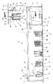
【図2】図1の装置の一部としての中間貯蔵庫の拡大図。
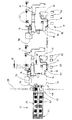
【図3】図2の矢印IIIにしたがう側面における中間貯蔵庫を示す。
【図4】図2のIV‐IV面に沿う中間貯蔵庫の横断方向断面図。
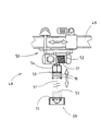
【図5】 V‐V面に沿うパレットコンベヤーを指向する区域を備える中間貯蔵庫の断面図。
【図6】リールコンベヤーの図を伴う図5と同様の図。
【図7】オーバーヘッドコンベヤーの細部すなわちリールコンベヤーの側面図。
【図8】リールの(中間)貯蔵部の細部すなわち中間コンベヤーの側面図。
【図9】図1のIX‐IX断面にしたがうリールコンベヤーを備える包装機の区域における細部の横断方向図。
【図10】リールコンベヤーによって1つのリールが分配された後の図9と同様な図。
【符号の説明】
10…ライン,11…ライン,12…中間貯蔵庫,18…リール,20…パレット,21…架台,25…移送ステーション,26…パレットキャリッジ,28…パレットコンベヤー,29…移動キャリッジ,30…走行レール,33…固定手段,39…荷役ロボット,48…リールコンベヤー,49…走行レール,50…移動機構,51…牽引ケーブル,53…リールキャリアー,59…中間コンベヤー,71…負荷支持パネル。[0001]
BACKGROUND OF THE INVENTION
The present invention relates to an apparatus for supplying consumable materials, ie packaging materials, to a manufacturing and packaging machine, in particular as a glued material web-reel, which are supplied (individually) to a pallet surface. Distributed to manufacturing and packaging machines.
[0002]
[Prior art]
In the cigarette industry, the challenge of supplying high-productivity machines raises special problems. This problem is associated with supplying materials to machines that manufacture and package cigarettes or similar products. The material used exclusively is a web-like material which is used in a glued form, ie as a reel.
[0003]
The known apparatus works with industrial carts, i.e. transport vehicles traveling along the floor of the production plant, and transfers reels arranged on the pallet surface to separate packaging machines. However, there are already known devices for transferring reels from a central stockpile to a separate point of use via an overhead conveyor set up for automated work.
[0004]
[Problems to be solved by the invention]
The object of the present invention is to propose a highly productive device for supplying reels that are constructed and operated at low cost, especially for manufacturing and packaging machines.
[0005]
[Means for Solving the Problems]
In order to achieve this object, the apparatus of the present invention is characterized by the following points.
[0006]
(a) A transfer station (25) is formed in an area directly adjacent to the intermediate storage (12), in which a pallet conveyor (28) for supplying pallets (20) to the intermediate storage (12). Is running
(b) The pallet conveyor (28) is designed as an overhead conveyor with a transfer carriage (29) that can be moved along a traveling rail (30) in a high position, to which a plurality of pallets (20) A lifting mechanism (31) for moving the fixing means (33) up and down is provided.
(c) The reel conveyor (48) is also designed as an overhead conveyor, in the area of the transfer station (25), with the help of the reel carrier (53), the reel (18 The reel carrier (53) is attached to the lifting cable (51) of the reel conveyor (48) and can move up and down.
(d) The pallet (20) can be transferred by the pallet carriage (26) in the area of the intermediate storage (12), and the pallet (20) arriving after loading the reel (28) is transferred to the transfer station ( 25) can be placed on the surface of the pallet carriage (26) by the pallet conveyor (28)
(e) The reel (18) can be transferred by the cargo handling robot (39) in the area of the intermediate storage (12) to be received by the reel conveyor (48), said cargo handling robot being in the intermediate storage (12 The robot has a lifting head (47) for the reel (18) that can be moved above the pallet (20) loaded with the reel (18) stored in [0010]
The essential basic idea of the present invention is that different transfer systems customarily made for individual tasks are used for different transfer tasks within the manufacturing and packaging facilities. In the context of this invention, it is a conveyor that is set up for automatic work, in the area of the (intermediate) storage for the reel, whose working area is limited to the material storage, in particular with the aid of suitable sensors. Thus, a conveyor is provided with a lifting head for the reel that automatically selects the identifying feature. The reel identifying feature is a feature that can be used to automatically grip the reel for storage on a reel conveyor when the reel is to be transported further. This conveyor is in particular a cargo handling robot. The reel conveyor is set up as a “straight conveyor” as opposed to a handling robot, ie as an overhead conveyor with a linear transfer mechanism and a lifting mechanism. The reel conveyor has a lifting head that simply moves up and down. In order to function satisfactorily, the reels are in each case distributed by the handling robot to receiving means in the area of the material storage. This receiving means occupies a precise position with respect to the movement path of the reel conveyor. At the same time, the area of the material consuming machine is likewise provided with a set position which is precisely located in the transfer area machine of the reel conveyor.
[0011]
The structure of the (intermediate) storage, which comprises a plurality of pallets for any type of reel to be processed and a special pallet conveyor or pallet carriage constitute another feature. This intermediate storage has a transfer station in which a reel conveyor and a conveyor-pallet conveyor for moving the pallet up and down run.
[0012]
Another aspect of the invention relates to the structure of the intermediate storage and reel or pallet conveyor.
[0013]
Other details of this invention are identified and explained below with reference to exemplary embodiments of equipment for producing and packaging cigarettes.
[0014]
DETAILED DESCRIPTION OF THE INVENTION
The accompanying drawings show the manufacture and packaging of cigarettes. One apparatus or unit shown schematically in FIG. 1 has two
[0015]
The
[0016]
The
[0017]
Within the
[0018]
The
[0019]
In the area of the
[0020]
The
[0021]
One (new)
[0022]
[0023]
[0024]
One lifting means for raising and lowering, in this case a
[0025]
The
[0026]
A separate conveyor, i.e. a
[0027]
One
[0028]
In the present exemplary embodiment, the
[0029]
The
[0030]
The handling of the
[0031]
The intermediate conveyor or
[0032]
The
[0033]
A
[0034]
In order to produce a (cigarette) pack, it is also possible to use additional or other materials which are not advantageously provided as reels or in the
[0035]
The empty pallet is placed on the
[0036]
The apparatus described above and shown in FIG. 1 as a whole is advantageously provided in a production facility, more precisely, a plurality of
[Brief description of the drawings]
FIG. 1 is a schematic plan view of a machine unit including an intermediate storage.
FIG. 2 is an enlarged view of an intermediate storage as part of the apparatus of FIG.
3 shows an intermediate storage on the side according to arrow III in FIG.
4 is a transverse cross-sectional view of the intermediate storage along the IV-IV plane of FIG. 2. FIG.
FIG. 5 is a cross-sectional view of an intermediate storage with an area directed to a pallet conveyor along the VV plane.
6 is a view similar to FIG. 5 with a view of the reel conveyor.
FIG. 7 is a side view of an overhead conveyor detail or reel conveyor.
FIG. 8 is a detail of the reel (intermediate) reservoir, ie a side view of the intermediate conveyor.
9 is a cross-sectional view of details in a section of a packaging machine with a reel conveyor according to the IX-IX section of FIG.
FIG. 10 is a view similar to FIG. 9 after one reel has been dispensed by the reel conveyor.
[Explanation of symbols]
DESCRIPTION OF
Claims (6)
前記材料ウエブは、リール(18)として捲着され、リール(18)を、パレットコンベヤー(28)によってパレット(20)に供給し、パレット(20)を中間貯蔵庫(12)に載置し、リールコンベヤー(48)によって、個々のリール(18)を中間貯蔵庫(12)から供給しようとする製造機および包装機の1つに移送することができる、下記の(a)〜(e)を特徴とする装置。
(a)中間貯蔵庫(12)と直接隣接した区域に、移送ステーション(25)が形成され、前記区域内には、パレット(20)を中間貯蔵庫(12)に供給するためのパレットコンベヤー(28)が走行している
(b) パレットコンベヤー(28)は、高位置にある走行レール(30)に沿って移動されることができる移送キャリッジ(29)を備えるオーバーヘッドコンベヤーとして設計され、これに、複数のパレット(20)の固定手段(33)を上下に移動するための持ち上げ機構(31)が設けられている
(c)リールコンベヤー(48)もまた、オーバーヘッドコンベヤーとして設計されており、移送ステーション(25)の区域において、リールキャリヤー(53)の助けを借りて、製造機および包装機に移送されるリール(18)を受け取り、前記リールキャリヤー(53)は、リールコンベヤー(48)の持ち上げケーブル(51)に取り付けられており、上下移動することができる
(d)パレット(20)は、パレットキャリッジ(26)によって、中間貯蔵庫(12)の区域において移送されることができ、リール(28)を装填して到着するパレット(20)が、移送ステーション(25)の区域において、パレットコンベヤー(28)によってパレットキャリッジ(26)の面上に載置されることができる
(e)リール(18)は、リールコンベヤー(48)によって受け取られるために、中間貯蔵庫(12)の区域において、荷役ロボット(39)によって移送することができ、前記荷役ロボットは、中間貯蔵庫(12)内に貯蔵されているリール(18)を装填したパレット(20)の上方で移動することができ、前記ロボットは、自動制御が可能なリール(18)用の持ち上げヘッド(47)を有しているAn apparatus for supplying a material web made of consumer materials to a manufacturing machine and a packaging machine, that is, a packaging material,
The material web is attached as a reel (18), the reel (18) is supplied to the pallet (20) by the pallet conveyor (28), the pallet (20) is placed on the intermediate storage (12), and the reel It is characterized by the following (a) to (e), in which the individual reels (18) can be transferred from the intermediate storage (12) to one of the manufacturing machines and packaging machines by the conveyor (48). Device to do.
(a) A transfer station (25) is formed in an area directly adjacent to the intermediate storage (12), in which a pallet conveyor (28) for supplying pallets (20) to the intermediate storage (12). Is running
(b) The pallet conveyor (28) is designed as an overhead conveyor with a transfer carriage (29) that can be moved along a traveling rail (30) at a high position, to which a plurality of pallets (20) A lifting mechanism (31) for moving the fixing means (33) up and down is provided.
(c) The reel conveyor (48) is also designed as an overhead conveyor, and in the area of the transfer station (25), with the help of the reel carrier (53), the reel ( 18), the reel carrier (53) is attached to the lifting cable (51) of the reel conveyor (48) and can move up and down.
(d) The pallet (20) can be transferred by the pallet carriage (26) in the area of the intermediate storage (12), and the pallet (20) arriving after loading the reel (28) is transferred to the transfer station ( 25) can be placed on the surface of the pallet carriage (26) by the pallet conveyor (28)
(e) The reel (18) can be transported by the cargo handling robot (39) in the area of the intermediate storage (12) to be received by the reel conveyor (48), said cargo handling robot being in the intermediate storage (12 The robot has a lifting head (47) for the reel (18) that can be moved above the pallet (20) loaded with the reel (18) stored in ing
Applications Claiming Priority (4)
| Application Number | Priority Date | Filing Date | Title |
|---|---|---|---|
| DE2001109446 DE10109446A1 (en) | 2001-02-27 | 2001-02-27 | Packaging material supplying unit for packaging production machine in cigarette industry, has conveyor that transports reels in pallets from intermediate store to individual machines and sub-assemblies of lines |
| DE10109446.9 | 2001-02-27 | ||
| DE10152048.4 | 2001-10-25 | ||
| DE2001152048 DE10152048A1 (en) | 2001-10-25 | 2001-10-25 | Packaging material supplying unit for packaging production machine in cigarette industry, has conveyor that transports reels in pallets from intermediate store to individual machines and sub-assemblies of lines |
Publications (2)
| Publication Number | Publication Date |
|---|---|
| JP2002332104A JP2002332104A (en) | 2002-11-22 |
| JP4097955B2 true JP4097955B2 (en) | 2008-06-11 |
Family
ID=26008639
Family Applications (1)
| Application Number | Title | Priority Date | Filing Date |
|---|---|---|---|
| JP2002051115A Expired - Fee Related JP4097955B2 (en) | 2001-02-27 | 2002-02-27 | Equipment for supplying packaging materials to packaging machines |
Country Status (6)
| Country | Link |
|---|---|
| US (1) | US6718727B2 (en) |
| EP (1) | EP1273541B1 (en) |
| JP (1) | JP4097955B2 (en) |
| CN (1) | CN1298592C (en) |
| BR (1) | BR0200535B1 (en) |
| DE (1) | DE50210152D1 (en) |
Families Citing this family (31)
| Publication number | Priority date | Publication date | Assignee | Title |
|---|---|---|---|---|
| US20050120674A1 (en) * | 2002-07-30 | 2005-06-09 | Hauni Maschinenbau Ag | Apparatus for manufacturing and packaging cigarettes and arrangement of appropriate apparatuses |
| DE10344675A1 (en) * | 2003-09-25 | 2005-04-14 | Focke & Co.(Gmbh & Co. Kg) | Cigarette packaging manufacturing method in which at least coupon or tax stamp is added to each cigarette packet by use of storage magazines for transfer of finished coupons to packaging system |
| CN100445170C (en) * | 2005-06-04 | 2008-12-24 | 李法岗 | Dual-line packing machine able to automatically making bags and filling material in bag |
| DE102005060638A1 (en) * | 2005-12-13 | 2007-06-14 | Hauni Maschinenbau Ag | Bobbins handling device, has mechanism with bobbin handling unit that is arranged in such a manner that it is vertically movable in Z-direction to slides, which are movable along vertical axis |
| DE102006017379A1 (en) * | 2006-04-11 | 2007-10-18 | Focke & Co.(Gmbh & Co. Kg) | Device for handling bobbins from packaging material |
| GB0701257D0 (en) * | 2007-01-23 | 2007-02-28 | British American Tobacco Co | Machine, method, and system for packaging smoking products |
| DE102009056247A1 (en) * | 2009-12-01 | 2011-06-09 | Focke & Co.(Gmbh & Co. Kg) | Device for handling large packs with a plurality of articles as package contents |
| DE102012101114A1 (en) * | 2012-02-14 | 2013-08-14 | Krones Ag | Device for providing consumables |
| US10676303B2 (en) | 2015-04-30 | 2020-06-09 | Krones Aktiengesellschaft | Method and apparatus for supplying, staging and for replacing rolls with flat material and/or film material wound thereonto |
| DE202015102191U1 (en) | 2015-04-30 | 2016-08-24 | Krones Aktiengesellschaft | Apparatus for conveying, providing and exchanging rolls of packaging material in a packaging machine |
| DE102015208118A1 (en) | 2015-04-30 | 2016-11-03 | Krones Aktiengesellschaft | Method and device for conveying, providing and exchanging rolls of packaging material in a packaging machine |
| DE102015208122A1 (en) | 2015-04-30 | 2016-11-03 | Krones Aktiengesellschaft | Method and device for conveying, providing and exchanging rolls of packaging material in a packaging machine |
| DE102015208136A1 (en) | 2015-04-30 | 2016-11-03 | Krones Aktiengesellschaft | Method and device for conveying, providing and exchanging rolls of packaging material in a packaging machine |
| DE102015208140A1 (en) | 2015-04-30 | 2016-11-03 | Krones Aktiengesellschaft | Packaging machine and method for conveying, providing and exchanging rolls of packaging material in such a packaging machine |
| DE102015208102A1 (en) | 2015-04-30 | 2016-11-03 | Krones Aktiengesellschaft | Method and device for conveying, providing and exchanging rolls of packaging material in a packaging machine |
| DE102015211620A1 (en) | 2015-06-23 | 2016-12-29 | Krones Aktiengesellschaft | Packaging machine and method for conveying, providing and exchanging rolls of packaging material in such a packaging machine |
| DE102015225914A1 (en) | 2015-12-18 | 2017-06-22 | Krones Aktiengesellschaft | Apparatus and method for conveying, providing and exchanging rolls of packaging material in a packaging machine |
| DE102016200581B4 (en) | 2016-01-19 | 2023-01-12 | Krones Aktiengesellschaft | Method for feeding, providing and exchanging rolls of packaging material in a packaging machine |
| DE102016206172A1 (en) | 2016-04-13 | 2017-10-19 | Krones Aktiengesellschaft | Apparatus and method for providing roll-wound packaging material for articles such as beverage containers or the like |
| DE102016206183A1 (en) | 2016-04-13 | 2017-10-19 | Krones Aktiengesellschaft | Method and apparatus for providing roll-wound packaging material for articles such as beverage containers or the like |
| DE102016206711A1 (en) | 2016-04-20 | 2017-10-26 | Krones Aktiengesellschaft | Method and device for handling packaging material wound on rolls |
| US10407251B2 (en) * | 2017-01-18 | 2019-09-10 | Kabushiki Kaisha Yaskawa Denki | Workpiece handling apparatus, workpiece handling system, method for discharging workpiece, method for supplying workpiece, and method for storing workpiece |
| CN106829029A (en) * | 2017-04-19 | 2017-06-13 | 佛山市卓翔机械设备有限公司 | The quick film covering device of ceramic tile |
| CN107081726A (en) * | 2017-06-07 | 2017-08-22 | 徐晓依 | A kind of storage tire rack |
| DE102018131992A1 (en) | 2018-12-12 | 2020-06-18 | Krones Aktiengesellschaft | Method and device for handling flat and / or film material designed for packaging articles |
| CN112110213A (en) * | 2019-06-21 | 2020-12-22 | 上海海立电器有限公司 | Stacking paw and air conditioner indoor unit carrying device |
| DE102021100035A1 (en) * | 2021-01-04 | 2022-07-07 | Krones Aktiengesellschaft | Transport device for supply rolls with wound up packaging material |
| CN114104744B (en) * | 2021-11-17 | 2024-02-09 | 威斯德(厦门)自动化有限公司 | Automatic Tray feeding and discharging production line and automatic Tray feeding and discharging method |
| CN115367344A (en) * | 2022-09-15 | 2022-11-22 | 楚能新能源股份有限公司 | Lithium battery production factory building |
| CN115285759B (en) * | 2022-10-08 | 2023-05-12 | 南通凯赛家纺有限公司 | Winding machine for cloth processing |
| CN116534668A (en) * | 2022-12-02 | 2023-08-04 | 苏州正齐半导体设备有限公司 | System for changing reels and method thereof |
Family Cites Families (24)
| Publication number | Priority date | Publication date | Assignee | Title |
|---|---|---|---|---|
| JPS5583590A (en) | 1978-12-12 | 1980-06-24 | Fuji Electric Co Ltd | Handling device |
| DE3151316C2 (en) | 1981-12-24 | 1986-09-18 | KK Automation Klaus Th. Krämer GmbH & Co KG, 7107 Neckarsulm | Handling system for workpieces |
| EP0107381A1 (en) | 1982-09-30 | 1984-05-02 | Harold M. Romanowitz | Material handling system and method |
| DE3408171A1 (en) | 1984-03-06 | 1985-10-24 | Anton 7892 Albbruck Müller | Transport device |
| IT1187368B (en) | 1985-05-10 | 1987-12-23 | Gd Spa | AUTOMATED FEEDING SYSTEM FOR PRODUCTION AND / OR PACKAGING MATERIAL FROM A WORK-LINE WAREHOUSE |
| DE3519580C1 (en) | 1985-05-31 | 1987-03-05 | Bat Cigarettenfab Gmbh | Installation for manufacturing and packaging cigarettes |
| DE3627670C1 (en) | 1985-05-31 | 1988-03-03 | Bat Cigarettenfab Gmbh | Plant for producing and packaging cigarettes |
| DE3526524A1 (en) | 1985-07-24 | 1987-02-05 | Siegmund Kumeth | DEVICE FOR THE AUTOMATIC ASSEMBLY OF WORKPIECES OR WORKPIECE PARTS, AND METHOD FOR CONTROLLING SUCH A DEVICE |
| DE3827917C2 (en) * | 1988-06-18 | 1998-07-09 | Focke & Co | Device for transporting packaging material to a packaging machine |
| DE3915139A1 (en) * | 1989-05-09 | 1990-11-15 | Focke & Co | METHOD AND SYSTEM FOR REORDERING SORTED PALLETED ITEMS TO GROUPS OF CERTAIN SORT ASSEMBLY |
| DE4018266C2 (en) | 1990-06-07 | 1997-10-02 | Bat Cigarettenfab Gmbh | Plant for the production and packaging of cigarettes |
| JPH04217501A (en) * | 1990-12-14 | 1992-08-07 | Kataoka Mach Co Ltd | Mill roll storing device |
| DE4041865A1 (en) * | 1990-12-27 | 1992-07-02 | Schmermund Maschf Alfred | Cigarette packing machine with bobbins of wrapping material - has bobbin transfer unit with intersliding jaws |
| IT1258006B (en) * | 1992-01-13 | 1996-02-20 | Gd Spa | SYSTEM AND METHOD FOR THE AUTOMATIC COLLECTION OF OBJECTS |
| DE4215739C2 (en) | 1992-05-13 | 1995-11-30 | Kleinewefers Gmbh | Method and device for loading and unloading rolls wound with a material web in a machine having a roll carrier with several roller positions for processing the material web, in particular a printing machine |
| DE4225337A1 (en) | 1992-07-31 | 1994-02-03 | Grob Gmbh & Co Kg | Assembly line for vehicle IC-engines - has workpiece carrier holding parts in fixed relative positions so that identical parts to be assembled can be picked and placed by gripper while carrier is shuttled by feed cam |
| IT1259440B (en) * | 1992-10-28 | 1996-03-18 | Gd Spa | SYSTEM WITH SEPARATE UNIT FOR THE FEEDING OF TAPE WRAPPING MATERIAL. |
| IT1264219B1 (en) * | 1993-09-20 | 1996-09-23 | Gd Spa | PLANT FOR THE REALIZATION AND PACKAGING OF SMOKING ITEMS, IN PARTICULAR CIGARETTES. |
| IT1273218B (en) * | 1994-01-20 | 1997-07-07 | Gd Spa | COIL FEEDING DEVICE TO A USING MACHINE |
| DE4404929C2 (en) * | 1994-02-16 | 1995-12-14 | Bat Cigarettenfab Gmbh | Plant for the production and packaging of cigarettes |
| IT1268333B1 (en) * | 1994-09-16 | 1997-02-27 | Sasib Spa | OPERATING MACHINE SUITABLE FOR USING REELS OF MATERIAL TAPE, IN PARTICULAR PACKAGING MACHINE AND FOR THE PACKAGING OF |
| DE19531522C2 (en) | 1995-08-26 | 1998-07-09 | Bleichert Foerderanlagen Gmbh | Handling system for workpieces |
| DE19613817A1 (en) | 1996-04-08 | 1997-10-09 | Gerhard Kahl | Trolley for roller pallets, used in storage system of warehouse |
| DE19914297A1 (en) * | 1999-03-29 | 2000-10-05 | Focke & Co | Method and device for controlling a (cigarette) manufacturing and packaging system |
-
2002
- 2002-02-12 EP EP02003009A patent/EP1273541B1/en not_active Expired - Lifetime
- 2002-02-12 DE DE50210152T patent/DE50210152D1/en not_active Expired - Lifetime
- 2002-02-13 US US10/074,999 patent/US6718727B2/en not_active Expired - Fee Related
- 2002-02-27 BR BRPI0200535-2A patent/BR0200535B1/en not_active IP Right Cessation
- 2002-02-27 CN CNB021064105A patent/CN1298592C/en not_active Expired - Fee Related
- 2002-02-27 JP JP2002051115A patent/JP4097955B2/en not_active Expired - Fee Related
Also Published As
| Publication number | Publication date |
|---|---|
| EP1273541A2 (en) | 2003-01-08 |
| EP1273541A3 (en) | 2005-01-26 |
| US20020162299A1 (en) | 2002-11-07 |
| US6718727B2 (en) | 2004-04-13 |
| JP2002332104A (en) | 2002-11-22 |
| BR0200535A (en) | 2002-08-06 |
| CN1371844A (en) | 2002-10-02 |
| BR0200535B1 (en) | 2010-12-14 |
| CN1298592C (en) | 2007-02-07 |
| DE50210152D1 (en) | 2007-06-28 |
| EP1273541B1 (en) | 2007-05-16 |
Similar Documents
| Publication | Publication Date | Title |
|---|---|---|
| JP4097955B2 (en) | Equipment for supplying packaging materials to packaging machines | |
| US10781060B2 (en) | Storage and retrieval system transport vehicle | |
| US8998554B2 (en) | Multilevel vertical conveyor platform guides | |
| US11498784B2 (en) | Palletizer-depalletizer system for distribution facilities | |
| JPH0818671B2 (en) | Equipment for transporting packaging materials to packaging machines | |
| KR20170103964A (en) | Storage and retrieval system | |
| KR20160141843A (en) | Warehouse and retrieval truck for warehouse | |
| JPH03111313A (en) | Stocking, deliverying and restocking method of cassettes charged with materials in storage shelves | |
| KR20220047361A (en) | Delivery systems, automated storage and retrieval systems and container shipping methods | |
| KR20220018573A (en) | storage system | |
| JPH07112885B2 (en) | Transfer device | |
| DE10109446A1 (en) | Packaging material supplying unit for packaging production machine in cigarette industry, has conveyor that transports reels in pallets from intermediate store to individual machines and sub-assemblies of lines | |
| JP2001122404A (en) | Automatic dense accommodation facility | |
| JPH069019A (en) | Elevated storage unit | |
| JP3510045B2 (en) | Article storage facility | |
| EP0507575A1 (en) | Universal material carrier and overhead monorail system | |
| JP4090319B2 (en) | Package conversion method and package conversion equipment | |
| JP2985621B2 (en) | In / out transfer device | |
| KR200277232Y1 (en) | Cart for stacking freight | |
| JPH0351261A (en) | Moving type device for loading yarn package on pallet | |
| JP4151364B2 (en) | Case body storage method and case body storage equipment | |
| JP4545350B2 (en) | Spool supply device | |
| CN115848930A (en) | Storage system and optical fiber finished product production line | |
| JPS5934606B2 (en) | Automatic stacking device for spools | |
| JPH04183541A (en) | Assembling equipment using movable body |
Legal Events
| Date | Code | Title | Description |
|---|---|---|---|
| A621 | Written request for application examination |
Free format text: JAPANESE INTERMEDIATE CODE: A621 Effective date: 20041112 |
|
| A131 | Notification of reasons for refusal |
Free format text: JAPANESE INTERMEDIATE CODE: A131 Effective date: 20070320 |
|
| A601 | Written request for extension of time |
Free format text: JAPANESE INTERMEDIATE CODE: A601 Effective date: 20070620 |
|
| A602 | Written permission of extension of time |
Free format text: JAPANESE INTERMEDIATE CODE: A602 Effective date: 20070625 |
|
| A521 | Written amendment |
Free format text: JAPANESE INTERMEDIATE CODE: A523 Effective date: 20070920 |
|
| TRDD | Decision of grant or rejection written | ||
| A01 | Written decision to grant a patent or to grant a registration (utility model) |
Free format text: JAPANESE INTERMEDIATE CODE: A01 Effective date: 20080212 |
|
| A61 | First payment of annual fees (during grant procedure) |
Free format text: JAPANESE INTERMEDIATE CODE: A61 Effective date: 20080312 |
|
| R150 | Certificate of patent or registration of utility model |
Free format text: JAPANESE INTERMEDIATE CODE: R150 |
|
| FPAY | Renewal fee payment (event date is renewal date of database) |
Free format text: PAYMENT UNTIL: 20110321 Year of fee payment: 3 |
|
| FPAY | Renewal fee payment (event date is renewal date of database) |
Free format text: PAYMENT UNTIL: 20130321 Year of fee payment: 5 |
|
| FPAY | Renewal fee payment (event date is renewal date of database) |
Free format text: PAYMENT UNTIL: 20130321 Year of fee payment: 5 |
|
| FPAY | Renewal fee payment (event date is renewal date of database) |
Free format text: PAYMENT UNTIL: 20140321 Year of fee payment: 6 |
|
| R250 | Receipt of annual fees |
Free format text: JAPANESE INTERMEDIATE CODE: R250 |
|
| R250 | Receipt of annual fees |
Free format text: JAPANESE INTERMEDIATE CODE: R250 |
|
| LAPS | Cancellation because of no payment of annual fees |