JP4094609B2 - 管継手 - Google Patents
管継手 Download PDFInfo
- Publication number
- JP4094609B2 JP4094609B2 JP2004509308A JP2004509308A JP4094609B2 JP 4094609 B2 JP4094609 B2 JP 4094609B2 JP 2004509308 A JP2004509308 A JP 2004509308A JP 2004509308 A JP2004509308 A JP 2004509308A JP 4094609 B2 JP4094609 B2 JP 4094609B2
- Authority
- JP
- Japan
- Prior art keywords
- ring
- pipe
- pipe joint
- joint according
- flange
- Prior art date
- Legal status (The legal status is an assumption and is not a legal conclusion. Google has not performed a legal analysis and makes no representation as to the accuracy of the status listed.)
- Expired - Fee Related
Links
- 229920001971 elastomer Polymers 0.000 claims description 8
- 239000002184 metal Substances 0.000 claims description 6
- 239000000806 elastomer Substances 0.000 claims description 3
- 239000004033 plastic Substances 0.000 claims description 3
- 239000000463 material Substances 0.000 claims 1
- 230000008878 coupling Effects 0.000 abstract description 5
- 238000010168 coupling process Methods 0.000 abstract description 5
- 238000005859 coupling reaction Methods 0.000 abstract description 5
- 239000012530 fluid Substances 0.000 description 3
- 238000000034 method Methods 0.000 description 2
- 230000002093 peripheral effect Effects 0.000 description 2
- 238000007789 sealing Methods 0.000 description 2
- RNFNDJAIBTYOQL-UHFFFAOYSA-N chloral hydrate Chemical compound OC(O)C(Cl)(Cl)Cl RNFNDJAIBTYOQL-UHFFFAOYSA-N 0.000 description 1
- 230000000295 complement effect Effects 0.000 description 1
- 239000002131 composite material Substances 0.000 description 1
- 230000007812 deficiency Effects 0.000 description 1
- 230000000694 effects Effects 0.000 description 1
- 239000013536 elastomeric material Substances 0.000 description 1
- 238000009434 installation Methods 0.000 description 1
- 238000012986 modification Methods 0.000 description 1
- 230000004048 modification Effects 0.000 description 1
- 238000010137 moulding (plastic) Methods 0.000 description 1
- 238000005096 rolling process Methods 0.000 description 1
- 238000007665 sagging Methods 0.000 description 1
- 230000009466 transformation Effects 0.000 description 1
Images


Classifications
-
- F—MECHANICAL ENGINEERING; LIGHTING; HEATING; WEAPONS; BLASTING
- F16—ENGINEERING ELEMENTS AND UNITS; GENERAL MEASURES FOR PRODUCING AND MAINTAINING EFFECTIVE FUNCTIONING OF MACHINES OR INSTALLATIONS; THERMAL INSULATION IN GENERAL
- F16L—PIPES; JOINTS OR FITTINGS FOR PIPES; SUPPORTS FOR PIPES, CABLES OR PROTECTIVE TUBING; MEANS FOR THERMAL INSULATION IN GENERAL
- F16L23/00—Flanged joints
- F16L23/02—Flanged joints the flanges being connected by members tensioned axially
- F16L23/024—Flanged joints the flanges being connected by members tensioned axially characterised by how the flanges are joined to, or form an extension of, the pipes
- F16L23/028—Flanged joints the flanges being connected by members tensioned axially characterised by how the flanges are joined to, or form an extension of, the pipes the flanges being held against a shoulder
- F16L23/0286—Flanged joints the flanges being connected by members tensioned axially characterised by how the flanges are joined to, or form an extension of, the pipes the flanges being held against a shoulder the shoulder not being formed from the pipe
Landscapes
- Engineering & Computer Science (AREA)
- General Engineering & Computer Science (AREA)
- Mechanical Engineering (AREA)
- Flanged Joints, Insulating Joints, And Other Joints (AREA)
- Gasket Seals (AREA)
- Supports For Pipes And Cables (AREA)
- Joints Allowing Movement (AREA)
- Paper (AREA)
- Quick-Acting Or Multi-Walled Pipe Joints (AREA)
Description
本発明は、密封して管を容器等のフランジに、または、互いに対して同心上に延在する管の二つの端部を接続するようにした形式の管継手に関する。
現在、上述の目的のために使用される最も普及している管継手は、蝶番式スプリットカラーとして知られた形式である。その形式は、一方の端部で互いにヒンジで取り付けられ、他端にラグを備える整合した一対の半円のカラーを含んでいる。そのカラーは、リムまたはその管の端部近傍に形成される相補的な外周溝に嵌まり保持するようにしたショルダーを有して形成される。エラストマーの円形ガスケットが使用され、その間の空間を囲み、その管の端部上方に部分的に延在する。互いに上に重なる各ラグを貫通するボルトにより、そのカラーが互いに締め付けられたならば、そのガスケットは、圧縮され、その管相互間で封止をもたらす。
その管に与えられる圧力は、ガスケットのさらなる加圧により、そのカラーのリムに対する封止効果を高めるために有効である。
これらのスプリットカラーカップリング(split collar couplings)は、最初の取付け段階中、確実な巧みな操作、および物理的な力を加えることを必要とし、本質的に使用について不便である。
その従来の継手の他の欠陥は、それらが金属で作られることを必要とし、それ故に、重く、かつ、保管および輸送空間の点からみて不経済である。
広範囲の種類の申し分のない異なる配管条件を可能とする簡単なプラスチックの一体成形構造の管継手を提供することが本発明の主な目的である。
スプリットカラーカップリングと連結して利用される標準の溝付管の端部を使用することが本発明のさらなる目的である。
本発明は、管を他の管にあるフランジに密封して接続するための管継手であって、管が外周の溝を有して形成され,ガスケット、取付用リングおよび取付用フランジを含む管継手において、リングは、伸縮自在に拡張可能であり、取付け用フランジがリングおよびカウンタフランジ双方に対し締め付けられるとき、溝に嵌まるようにされ管に取り付けられるリングを保持する突起手段を有して形成されることを特徴とする。
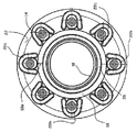
図1〜図5を参照するに、一組のボルト14によりフランジ12に結合される管10が示される。フランジ12は、溶接されるなどして管部16を介して例えば流体容器(不図示)の一部を形成し得る。
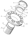
その継手は、3つの部品である分割取付用リング18、エラストマーガスケットリング20、および取付用フランジ22を含む。
図2および図5においてより明らかに分かるように、管10は、従来の蝶番式カラーカップリングと接続して使用されるものと類似した外周溝10aを備えて形成されている。
分割取付用リング18は、代表的には、プラスチックで作られ、溝10aに嵌まるように構成される円形リブ18aを有して形成されている。
リブ18aは、好ましくは、略鋸歯形状であり、その先端面18’aが、溝10aにおける直角の側壁にちょうどぴったりと合っている。さらに後述されるような理由から対向する面18a”は示されるような勾配がついている。
リング18は、さらに、ガスケット20をぴったりと受け止めるための円形の凹部18bを有して形成されている。
リング18の外側輪郭は、アップライトショルダー18dと一体化し、好ましくは、15°と30°との間の円錐面18cを有している。
結局、リング18は、管10の開口面にわたり押しやられる程度に広げる、即ち、拡張可能とするために切れ目18eにより分割されている。リング18は、さらにリブ18aが溝10aにカチッと音がするまで押し込まれる。
通常、ゴムまたは他の適したエラストマー材料のガスケット20は、好ましくは、 その技術において知られているような液体による流動圧下の拡張(「流体シール(hydraulic seal)」)用の内側溝20aを有して形成されている。
取付用フランジ22は、リング18の面18cの傾きおよび長さと同様な傾きおよび長さの内側円錐面22aを有している。その結果、ボルト14が締め付けられる場合、その継手の組立て位置においてガスケット20をフランジ12の面に対して密封することが要求されるとき、ショルダー18dに対し作用する軸方向の力成分を伴ってリング18回りの堅固な把持が実現される。
ボルト14用の孔22bを有するフランジ22は、好ましくは、ショルダー18cの幅に対応した弓形の突起部22cを有して形成されている。
その継手を組み立てる方法は、上述の説明を考慮すると自明である。図5から分かるように、先ず、フランジ22は、管10の上方に配置される。それから、取付用分割リング18は、その管の端部上方に強制的に揃えられ、それはリブ18aの傾斜部18a”により助けられる弾性的な拡張により容易とされる。即ち、リブ18aが溝(10a)の回りに把持する管10に適切に取り付けられたならば、ガスケット20が凹部18bに配置される。フランジ22は、リング18上方に締結用のフランジ12の方向に向かって引っ張られる。
ボルト14を使用したフランジ12および22の互いの締付けに耐えるために要求され、適度にガスケット20を圧縮する逆の力は、溝10a内に捕捉されるリブ18aにより、より正確には、溝10aの垂直壁に対する部分18a’の当接により与えられる。
その継手は、これまでほぼ述べた通りに、同一の参照数字がすでに同一とされる部品および要素を示すように使用される図6および図7に図示されるように、同一径(あるいは、等しくない径)の二つの管を接続するために容易に役立つ。
明らかに分かるように、「向き合った」係合関係の状態で二つの継手が用いられる。それ故、左手側管110は、フランジ222、取り囲む分割リング218、およびガスケット220(上述の実施例のようにフランジ12に固定されるのでなく)に締め付けられる取付用分割リング118、ガスケット120、および、取り付け用フランジ122により組み立てられる。従って、管110は、管210に気密状に接続されることになる。
幾つかの変更された実施例が説明され、本発明の多用性および他の利点を証明する。
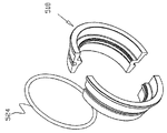
図8を参照するに、薄い垂れ縁、即ち、分割リング318の溝318eに挿入されるように設計されたタング320bを備えたガスケット320が例示されている。リング部相互間におけるその垂れ縁の位置決めにより、そのリングとその包囲する取付用フランジ(不図示)との間における寸法または表面の凹凸のいかなる偏差をも補うであろう柔軟性が付加され、製造中、厳密でない公差管理を可能とする。
図9における取付用分割リング418は、軸線方向に対しある角度の傾斜をもって延在する貫通したスロット418eを有して形成されている。
分割リングを用いることなく、リングがゴムバンド(それぞれ、524および624)により一緒に保持される複数の部分(図10においては、2個、図11においては、3個)からなることが可能である。
図12〜14における取付用リング718は、再び、変更された構造である。一連のメタルインサート726がその部分相互間に位置決めされている。ゴムバンド728は、すべての部分に通され、インサートは、管(不図示)への取り付けが要求されるとき、リング718の拡張を可能とする。このインサートは、その用途に合わせて取付けリングの形状に合致しており、即ち、歯718a(図1における連続したリブ18aを置き換える)および円錐形の外面718cを有している。
リング718における混成即ち複合の構造が、溝付きの管(不図示)に対してリングの強化された堅固な把持、ならびに、要求されている場合、接続された管相互間における電気的な近道を与える。
図15における取付けリング818は、プラスチック成形品により作られるのではなく、知られた技術(ローリング)により最終的な形状に加工されたシートメタルで作られる。その連続した円錐形の表面(図2において18cで示す)が二つに分けられていることに気付かれるだろう。部分818c’および部分818c”が取付用フランジ(不図示)における内側円錐形表面をともに適切に支持する。
この発明が関連する技術における当業者は、添付した請求の範囲により定義されるような本発明における真の精神および範囲から逸脱することなく、多数の変更、変形、および、修正が実現可能であることが容易に理解するだろう。
本発明におけるこれらおよび付加的な構造的特徴および利点は、添付図面を参照して例を挙げただけの幾つかの好ましい実施例の次の説明を考慮してより明確に了解されるだろう、図中。
管を流体容器の出口/入口フランジに接続するために使用されるとき、本発明の特徴を描写した管継手の断面図である。
拡大した図1の継手の細部を示す。
図1のIII−III線に沿った断面図である。
図1のIV−IV線に沿った断面図である。
図1の管継手の分解斜視図である。
一対の管を一緒に接続するために使用される本発明の他の実施例に従う管継手の断面図である。
拡大した図6の継手の細部を示す。
変形エラストマーガスケットを示す。
変形取付用スプリットリングを示す。
その取付用スプリットリングのさらなる変形を示す。
図10のリングの変形である。
混成の、多分割構造の取付用リングの斜視図である。
図12のリングの上面図である。
図13のXIV−XIV線に沿った断面図である。
シートメタルから加工された取付用分割リングを示す。
Claims (20)
- 管(10,110)を他の管(16,210)にあるフランジ(12,112)に密封して接続するための管継手であって、該管(10、110,210)が外周の溝(10a、110a,210a)を有して形成され,ガスケット(20、220)、取付用リング(18、118、218)および取付用フランジ(22、122、222)を含む管継手において、
前記リング(18、118、218)は、伸縮自在に拡張可能であり、前記取付け用フランジ(22、122、222)が前記リング(18、118,218)およびカウンタフランジ(12,222,122)双方に対し締め付けられるとき、前記溝(10a、110a,210a)に嵌まるようになされ前記管(10、110,210)に取り付けられる該リングを保持する突起手段(18a,110a,210a)を有して形成されることを特徴とする管継手。 - 前記リング(18,118,218)は、分割されている請求項1記載の管継手。
- 前記リング(18,118,218)は、軸平面に延在する切れ目により分割される請求項2記載の管継手。
- 前記リング(418)は非軸平面に延在する切れ目により分割される請求項2記載の管継手。
- 前記リング(18,118,218)は、プラスチック材料で作られる請求項1記載の管継手。
- 前記突起手段は、円形リブ(18a,118,218)を含む請求項1記載の管継手。
- 前記リブ(18a)は、直角面(18’)、および斜面(18a”)を有する略鋸歯形状である請求項6記載の管継手。
- 前記リング(18)は、エラストマーガスケット(20)を収容するように構成された円形の凹部(18b)を有して形成される請求項1記載の管継手。
- 前記ガスケット(20)は、内側溝(20a)を有して形成される請求項8記載の管継手。
- 前記ガスケット(320)は、薄い垂れ縁(320b)を有して形成される請求項9記載の管継手。
- 前記リング(18)は、外側円錐面(18c)を有している請求項1記載の管継手。
- 前記円錐の角度は、前記リング(18)の軸線に対して15°と30°との間である請求項11記載の管継手。
- アップライトショルダー(18d)が前記円錐面(18c)の端部の回りに延在する請求項12記載の管継手。
- 前記取付け用フランジ(22)は、前記リング(18)の円錐面(18c)に整合する内側円錐面(22a)を有して形成される請求項1記載の管継手。
- 前記取付け用フランジ(22)は、締付け用ボルト(14)が通過するようにした孔(22b)列を有して形成される請求項14記載の管継手。
- 前記孔(22b)は、弓形の突起(22c)により部分的に囲まれている請求項11記載の管継手。
- 前記リング(518、618)は、外側のゴムバンド(524,624)により一緒に保持される複数の部分からなる請求項1記載の管継手。
- メタルインサート(826)は、隣接する部分の間に介在される請求項17記載の管継手。
- 前記部分およびインサートは、その中を貫通されるゴムバンドにより一緒に保持される請求項18記載の管継手。
- 前記リング(818)は、シートメタルで作られる請求項1記載の管継手。
Applications Claiming Priority (1)
| Application Number | Priority Date | Filing Date | Title |
|---|---|---|---|
| PCT/IL2002/000427 WO2003102458A1 (en) | 2002-05-30 | 2002-05-30 | Pipe coupling |
Publications (2)
| Publication Number | Publication Date |
|---|---|
| JP2005528568A JP2005528568A (ja) | 2005-09-22 |
| JP4094609B2 true JP4094609B2 (ja) | 2008-06-04 |
Family
ID=29596284
Family Applications (1)
| Application Number | Title | Priority Date | Filing Date |
|---|---|---|---|
| JP2004509308A Expired - Fee Related JP4094609B2 (ja) | 2002-05-30 | 2002-05-30 | 管継手 |
Country Status (10)
| Country | Link |
|---|---|
| US (1) | US7527306B2 (ja) |
| EP (1) | EP1511958B1 (ja) |
| JP (1) | JP4094609B2 (ja) |
| AT (1) | ATE368818T1 (ja) |
| AU (1) | AU2002309226B2 (ja) |
| BR (1) | BR0211785B1 (ja) |
| DE (1) | DE60221577T2 (ja) |
| ES (1) | ES2291472T3 (ja) |
| IL (1) | IL165158A0 (ja) |
| WO (1) | WO2003102458A1 (ja) |
Families Citing this family (27)
| Publication number | Priority date | Publication date | Assignee | Title |
|---|---|---|---|---|
| FI118095B (fi) * | 2004-10-29 | 2007-06-29 | Maricap Oy | Putkiliitos |
| US7712797B2 (en) * | 2005-10-07 | 2010-05-11 | Grundfos Pumps Corporation | Universal fluid coupling assembly with interchangeable fitting members |
| KR100770167B1 (ko) | 2006-06-30 | 2007-10-26 | 주식회사동원프라스틱 | 관과 연결구가 일체로 형성된 내장형 아답터 플랜지관 연결조립체 |
| EP2150742B1 (en) * | 2007-04-27 | 2017-11-15 | Arconic Inc. | Method and apparatus for connecting drilling riser strings and compositions thereof |
| US7922218B2 (en) * | 2008-06-25 | 2011-04-12 | Dresser-Rand Company | Shear ring casing coupler device |
| US20120098259A1 (en) * | 2010-10-21 | 2012-04-26 | Armond Sarkisian | Gasket for piping |
| JP6013506B2 (ja) * | 2012-01-03 | 2016-10-25 | マイクロ モーション インコーポレイテッド | 流量計 |
| US9611960B2 (en) * | 2013-02-28 | 2017-04-04 | Spears Manufacturing Co. | Cut-in fitting for connecting pipe |
| MX363012B (es) | 2013-03-11 | 2019-03-04 | Imp Pipe Inc | Sistema de anillo de bloqueo de junta para tuberia revestida. |
| JP6242626B2 (ja) * | 2013-08-09 | 2017-12-06 | コスモ工機株式会社 | 管継手 |
| USD725759S1 (en) | 2014-04-03 | 2015-03-31 | M & D Wholesale Distributors, Inc. | Humidity control device |
| US9005348B2 (en) * | 2014-04-03 | 2015-04-14 | M&D Wholesale Distributors, Inc. | Segmented portable humidity control device for an enclosed volume storage device |
| GB2527360A (en) * | 2014-06-20 | 2015-12-23 | Spirax Sarco Ltd | Flange fitting |
| JP6549886B2 (ja) * | 2015-04-27 | 2019-07-24 | 株式会社モリタ環境テック | 無溶接フランジ管継手 |
| US11287076B2 (en) * | 2016-12-02 | 2022-03-29 | Total Piping Solutions, Inc. | Encapsulation sleeve gasket assembly with detachable inner layer |
| CA3045453A1 (en) | 2016-12-02 | 2018-06-07 | Total Piping Solutions, Inc. | Encapsulation sleeve gasket assembly with removable inner layer |
| US11506312B2 (en) | 2016-12-02 | 2022-11-22 | Total Piping Solutions, Inc. | Encapsulation sleeve gasket assembly with detachable inner layer |
| US10228056B2 (en) | 2016-12-22 | 2019-03-12 | North American Pipe Corporation | System, method and apparatus for seal marker |
| BR102017018910A2 (pt) | 2017-09-04 | 2019-03-19 | Jose Anisio De Oliveira E Silva | Anel compósito de suporte para soldas de topo e sistema que emprega o dito anel na fabricação de juntas de topo soldadas de seções tubulares metálicas revestidas internamente com materiais sensíveis ao calor |
| EP3460306A1 (de) * | 2017-09-20 | 2019-03-27 | FiberSol GmbH | Rohr mit verbindungsflansch |
| JP6914302B2 (ja) * | 2017-09-28 | 2021-08-04 | コスモ工機株式会社 | 管継手 |
| US10788153B2 (en) * | 2017-12-06 | 2020-09-29 | Lindsay Corporation | Joint assembly for fluid carrying pipes |
| EP3921564B1 (en) * | 2019-02-08 | 2024-06-05 | Total Piping Solutions, Inc. | Encapsulation sleeve gasket assembly with detachable inner layer |
| RU2706950C1 (ru) * | 2019-05-31 | 2019-11-22 | Общество с ограниченной ответственностью «Клеверенс Софт» | Способ радиочастотной идентификации насосно-компрессорных труб |
| MX2023001376A (es) | 2020-08-05 | 2023-03-03 | Lps Ip Llc | Conexion sellada de tuberia, manga para tuberia y sellos de tuberia bloqueables y metodo de fabricacion de los mismos. |
| WO2022031769A1 (en) | 2020-08-05 | 2022-02-10 | Lps Ip, Llc | Sealed pipeline connection and raised pipeline sleeve, and method of making same |
| CN117146078A (zh) * | 2023-07-05 | 2023-12-01 | 湖北大洋塑胶有限公司 | 复合管材 |
Family Cites Families (23)
| Publication number | Priority date | Publication date | Assignee | Title |
|---|---|---|---|---|
| US3124502A (en) * | 1964-03-10 | Composite fibrous lubricant packing | ||
| US1365530A (en) * | 1919-11-10 | 1921-01-11 | Moore William Davis | Pipe-joint |
| US1556745A (en) * | 1924-01-05 | 1925-10-13 | Robert R Banta | Pipe connection |
| US1821867A (en) * | 1930-02-28 | 1931-09-01 | Wylie G Wilson | Joint structure for pipes and the like |
| US1942489A (en) * | 1932-08-23 | 1934-01-09 | S R Dresser Mfg Co | Gasket |
| US1976589A (en) * | 1933-04-20 | 1934-10-09 | Lock Joint Pipe Co | Pipe joint |
| US1984806A (en) * | 1933-06-03 | 1934-12-18 | S R Dresser Mfg Co | Gasket for pipe joints and clamps |
| US2531922A (en) * | 1945-02-08 | 1950-11-28 | Pidco Ltd | Pipe coupling and the like |
| US2779610A (en) * | 1950-05-23 | 1957-01-29 | Dresser Ind | Sealed pipe coupling with constrictible wedge bushing |
| US2786697A (en) * | 1952-01-17 | 1957-03-26 | Eternit Werke Hatschek L | Pressure sealed flexible pipe coupling |
| US3284112A (en) * | 1963-12-11 | 1966-11-08 | Horace T Potts Company | Rotatable flange adjustable pipe coupling |
| US3381983A (en) * | 1965-08-16 | 1968-05-07 | Ventura Tool Company | Connectible and disconnectible tool joints |
| US3652110A (en) * | 1970-03-05 | 1972-03-28 | Douglas N Manton | Formation of joints between tubular members |
| US3761114A (en) * | 1971-08-30 | 1973-09-25 | Victaulic Co Ltd | Pipe to flange couplings |
| DE2226151C2 (de) * | 1972-05-29 | 1974-06-27 | Georg 8000 Muenchen Seiler | Steckmuffenverbindung von Rohren oder Rohrelementen, insbesondere aus Metall |
| CA975024A (en) * | 1973-07-31 | 1975-09-23 | Coupco Limited | Flange adaptor |
| US4101112A (en) * | 1976-11-24 | 1978-07-18 | Conners John A | Pipe line coupling system |
| US4488741A (en) * | 1983-01-31 | 1984-12-18 | Kerotest Manufacturing Corp. | Compression coupling for service valve |
| CA51586S (en) * | 1983-03-29 | 1983-07-18 | Canron Inc | Backing ring used to connect pipe sections |
| US5092636A (en) * | 1990-10-04 | 1992-03-03 | James P. Judge | Sealing ring disposed in recessed flange member |
| US5779285A (en) * | 1996-02-27 | 1998-07-14 | Perfection Corporation | Pipe coupling assembly |
| FR2775328B1 (fr) * | 1998-02-26 | 2000-04-28 | Christian Loth | Joint d'etancheite pour bride de tuyauterie |
| US6394507B1 (en) * | 1999-10-18 | 2002-05-28 | William J. Baker | Apparatus for connecting tubular bodies |
-
2002
- 2002-05-30 WO PCT/IL2002/000427 patent/WO2003102458A1/en not_active Ceased
- 2002-05-30 US US10/516,447 patent/US7527306B2/en not_active Expired - Fee Related
- 2002-05-30 EP EP02735944A patent/EP1511958B1/en not_active Expired - Lifetime
- 2002-05-30 JP JP2004509308A patent/JP4094609B2/ja not_active Expired - Fee Related
- 2002-05-30 AT AT02735944T patent/ATE368818T1/de not_active IP Right Cessation
- 2002-05-30 BR BRPI0211785-1A patent/BR0211785B1/pt not_active IP Right Cessation
- 2002-05-30 AU AU2002309226A patent/AU2002309226B2/en not_active Ceased
- 2002-05-30 DE DE60221577T patent/DE60221577T2/de not_active Expired - Lifetime
- 2002-05-30 ES ES02735944T patent/ES2291472T3/es not_active Expired - Lifetime
-
2004
- 2004-11-10 IL IL16515804A patent/IL165158A0/xx not_active IP Right Cessation
Also Published As
| Publication number | Publication date |
|---|---|
| DE60221577T2 (de) | 2008-04-17 |
| US7527306B2 (en) | 2009-05-05 |
| AU2002309226B2 (en) | 2008-09-18 |
| EP1511958B1 (en) | 2007-08-01 |
| IL165158A0 (en) | 2005-12-18 |
| AU2002309226A1 (en) | 2003-12-19 |
| US20050225089A1 (en) | 2005-10-13 |
| EP1511958A1 (en) | 2005-03-09 |
| JP2005528568A (ja) | 2005-09-22 |
| WO2003102458A1 (en) | 2003-12-11 |
| BR0211785B1 (pt) | 2011-01-11 |
| ES2291472T3 (es) | 2008-03-01 |
| DE60221577D1 (de) | 2007-09-13 |
| ATE368818T1 (de) | 2007-08-15 |
| BR0211785A (pt) | 2004-08-03 |
Similar Documents
| Publication | Publication Date | Title |
|---|---|---|
| JP4094609B2 (ja) | 管継手 | |
| US4779900A (en) | Segmented pipe joint retainer glands | |
| US5020832A (en) | Flexible pipe saddle | |
| US4518177A (en) | Hubless pipe coupling | |
| US4026586A (en) | Plain end pipe joint | |
| US4896903A (en) | Segmented pipe joint retainer glands | |
| KR101678379B1 (ko) | 관 연결 조립장치 | |
| JP2000035172A (ja) | 自在パイプコネクタ及びそのためのシ―リング素子 | |
| JPS6124593B2 (ja) | ||
| ITRM20120201U1 (it) | Connettore per collegare due estremità di tubatura. | |
| US5868438A (en) | Self-restrained adapter system for connecting plastic pipe system to metallic pipe system | |
| US3652110A (en) | Formation of joints between tubular members | |
| US4722555A (en) | Quick-connect coupling having heads unified with pipe | |
| US4295668A (en) | Adapter for connecting plastic pipe system to cast iron pipe system | |
| CN204628854U (zh) | 改进型空气管道快速连接头 | |
| US3368831A (en) | Coupling device | |
| JP3822021B2 (ja) | 管継手の連結方法及び管継手構造 | |
| JP3904698B2 (ja) | 管の固定装置 | |
| GB2305481A (en) | Pipe coupling with gasket and housing | |
| JPH04244692A (ja) | 可撓性管継手用相フランジ | |
| JPH11108267A (ja) | 管継手 | |
| JPH11108270A (ja) | 異管種接合用継ぎ輪 | |
| KR200296078Y1 (ko) | 배수관용 파이프 연결구 | |
| JP2702069B2 (ja) | 銅管などの可塑性管の接手装置 | |
| JP7054518B2 (ja) | 離脱防止管継手、及び、管継手の離脱防止方法 |
Legal Events
| Date | Code | Title | Description |
|---|---|---|---|
| A521 | Request for written amendment filed |
Free format text: JAPANESE INTERMEDIATE CODE: A523 Effective date: 20051007 |
|
| TRDD | Decision of grant or rejection written | ||
| A01 | Written decision to grant a patent or to grant a registration (utility model) |
Free format text: JAPANESE INTERMEDIATE CODE: A01 Effective date: 20080208 |
|
| A61 | First payment of annual fees (during grant procedure) |
Free format text: JAPANESE INTERMEDIATE CODE: A61 Effective date: 20080305 |
|
| FPAY | Renewal fee payment (event date is renewal date of database) |
Free format text: PAYMENT UNTIL: 20110314 Year of fee payment: 3 |
|
| R150 | Certificate of patent or registration of utility model |
Free format text: JAPANESE INTERMEDIATE CODE: R150 |
|
| LAPS | Cancellation because of no payment of annual fees |