JP4088728B2 - Planar motor device, driving device and exposure device - Google Patents
Planar motor device, driving device and exposure device Download PDFInfo
- Publication number
- JP4088728B2 JP4088728B2 JP19387898A JP19387898A JP4088728B2 JP 4088728 B2 JP4088728 B2 JP 4088728B2 JP 19387898 A JP19387898 A JP 19387898A JP 19387898 A JP19387898 A JP 19387898A JP 4088728 B2 JP4088728 B2 JP 4088728B2
- Authority
- JP
- Japan
- Prior art keywords
- motor device
- base
- vacuum chamber
- moving surface
- planar motor
- Prior art date
- Legal status (The legal status is an assumption and is not a legal conclusion. Google has not performed a legal analysis and makes no representation as to the accuracy of the status listed.)
- Expired - Fee Related
Links
Images
Classifications
-
- G—PHYSICS
- G03—PHOTOGRAPHY; CINEMATOGRAPHY; ANALOGOUS TECHNIQUES USING WAVES OTHER THAN OPTICAL WAVES; ELECTROGRAPHY; HOLOGRAPHY
- G03F—PHOTOMECHANICAL PRODUCTION OF TEXTURED OR PATTERNED SURFACES, e.g. FOR PRINTING, FOR PROCESSING OF SEMICONDUCTOR DEVICES; MATERIALS THEREFOR; ORIGINALS THEREFOR; APPARATUS SPECIALLY ADAPTED THEREFOR
- G03F7/00—Photomechanical, e.g. photolithographic, production of textured or patterned surfaces, e.g. printing surfaces; Materials therefor, e.g. comprising photoresists; Apparatus specially adapted therefor
- G03F7/70—Microphotolithographic exposure; Apparatus therefor
- G03F7/70691—Handling of masks or workpieces
- G03F7/70716—Stages
-
- G—PHYSICS
- G03—PHOTOGRAPHY; CINEMATOGRAPHY; ANALOGOUS TECHNIQUES USING WAVES OTHER THAN OPTICAL WAVES; ELECTROGRAPHY; HOLOGRAPHY
- G03F—PHOTOMECHANICAL PRODUCTION OF TEXTURED OR PATTERNED SURFACES, e.g. FOR PRINTING, FOR PROCESSING OF SEMICONDUCTOR DEVICES; MATERIALS THEREFOR; ORIGINALS THEREFOR; APPARATUS SPECIALLY ADAPTED THEREFOR
- G03F7/00—Photomechanical, e.g. photolithographic, production of textured or patterned surfaces, e.g. printing surfaces; Materials therefor, e.g. comprising photoresists; Apparatus specially adapted therefor
- G03F7/70—Microphotolithographic exposure; Apparatus therefor
- G03F7/70691—Handling of masks or workpieces
- G03F7/70758—Drive means, e.g. actuators, motors for long- or short-stroke modules or fine or coarse driving
-
- G—PHYSICS
- G03—PHOTOGRAPHY; CINEMATOGRAPHY; ANALOGOUS TECHNIQUES USING WAVES OTHER THAN OPTICAL WAVES; ELECTROGRAPHY; HOLOGRAPHY
- G03F—PHOTOMECHANICAL PRODUCTION OF TEXTURED OR PATTERNED SURFACES, e.g. FOR PRINTING, FOR PROCESSING OF SEMICONDUCTOR DEVICES; MATERIALS THEREFOR; ORIGINALS THEREFOR; APPARATUS SPECIALLY ADAPTED THEREFOR
- G03F7/00—Photomechanical, e.g. photolithographic, production of textured or patterned surfaces, e.g. printing surfaces; Materials therefor, e.g. comprising photoresists; Apparatus specially adapted therefor
- G03F7/70—Microphotolithographic exposure; Apparatus therefor
- G03F7/708—Construction of apparatus, e.g. environment aspects, hygiene aspects or materials
- G03F7/70858—Environment aspects, e.g. pressure of beam-path gas, temperature
-
- H—ELECTRICITY
- H02—GENERATION; CONVERSION OR DISTRIBUTION OF ELECTRIC POWER
- H02K—DYNAMO-ELECTRIC MACHINES
- H02K41/00—Propulsion systems in which a rigid body is moved along a path due to dynamo-electric interaction between the body and a magnetic field travelling along the path
- H02K41/02—Linear motors; Sectional motors
- H02K41/03—Synchronous motors; Motors moving step by step; Reluctance motors
- H02K41/031—Synchronous motors; Motors moving step by step; Reluctance motors of the permanent magnet type
-
- H—ELECTRICITY
- H02—GENERATION; CONVERSION OR DISTRIBUTION OF ELECTRIC POWER
- H02K—DYNAMO-ELECTRIC MACHINES
- H02K2201/00—Specific aspects not provided for in the other groups of this subclass relating to the magnetic circuits
- H02K2201/18—Machines moving with multiple degrees of freedom
Landscapes
- Physics & Mathematics (AREA)
- General Physics & Mathematics (AREA)
- Engineering & Computer Science (AREA)
- Health & Medical Sciences (AREA)
- Atmospheric Sciences (AREA)
- Epidemiology (AREA)
- Electromagnetism (AREA)
- Life Sciences & Earth Sciences (AREA)
- Combustion & Propulsion (AREA)
- Toxicology (AREA)
- Environmental & Geological Engineering (AREA)
- Power Engineering (AREA)
- Public Health (AREA)
- Chemical & Material Sciences (AREA)
- Exposure And Positioning Against Photoresist Photosensitive Materials (AREA)
- Linear Motors (AREA)
- Container, Conveyance, Adherence, Positioning, Of Wafer (AREA)
- Exposure Of Semiconductors, Excluding Electron Or Ion Beam Exposure (AREA)
- Motor Or Generator Cooling System (AREA)
Description
【0001】
【発明の属する技術分野】
本発明は、平面モータ装置及び露光装置に係り、さらに詳しくは、磁石ユニットを含む可動子を電磁力により2次元方向に駆動する平面モータ装置、及び該平面モータ装置を基板ステージ装置に用いた露光装置に関する。
【0002】
【従来の技術】
従来より、半導体素子、液晶表示素子等を製造するためのリソグラフィ工程では、マスク又はレチクル(以下、「レチクル」と総称する)に形成されたパターンを投影光学系を介してレジスト等が塗布されたウエハ又はガラスプレート等の基板上に転写する露光装置が用いられている。
【0003】
この露光装置では、ウエハを高精度に露光位置に位置決めする必要があるため、ウエハはウエハホルダ上に真空吸着等によって保持され、このウエハホルダがウエハテーブル上に固定されている。
【0004】
最近では、ウエハをより高速に、機械的な案内面の精度等に影響されず高精度に位置決めするとともに、かつ機械的な摩擦を回避して長寿命とするために、ウエハが載置されたテーブルを非接触で2次元方向に駆動することにより、ウエハを位置決めするステージ装置が開発されている。かかる非接触駆動のステージ装置の駆動源としては、可変磁気抵抗駆動方式のリニアパルスモータを2軸分結合させた構造の平面モータが、知られている。
【0005】
可変磁気抵抗駆動方式の平面モータとしては、現状では、ソイヤモータのように可変磁気抵抗駆動方式のリニアパルスモータを2軸分結合させた構造が主流である。この可変磁気抵抗駆動方式のリニアパルスモータは、例えば、凸凹状の歯部が長手方向に沿って等間隔に形成された板状の磁性体によって構成された固定子と、該固定子の凸凹状の歯部と対向し、この凸凹状歯部とは異なる位相の凸凹部を有する複数の電機子コイルが永久磁石を介して連結された可動子とを備える。そして、各時点における固定子との可動子との間の磁気抵抗を最小にしようとして発生する力を利用して、可動子を駆動する。すなわち、各電機子コイルに供給されるパルス電流の電流値及び位相を調整・制御することにより可動子をステップ状に歩進動作させる。
【0006】
【発明が解決しようとする課題】
上述した可変磁気抵抗駆動方式の平面モータを、精密位置決めに用いて高速な位置決めを実現するためには、大きな駆動力を得ることが必要となるが、このためには電機子コイルに必然的に大きな電流を流さなければならない。そのため、電機子コイルの発熱が大きな問題となる。
【0007】
また、リニアモータを2次元方向に展開したローレンツ電磁力駆動による平面モータも開発されている(例えば米国特許(USP)第5196745号公報参照)。かかるローレンツ電磁力式の平面モータは、制御性、推力線形性、位置決め性に優れていることから、将来的にはステージ駆動源として有力であると言われている。しかし、かかるローレンツ電磁力駆動の平面モータにおいても、大きな推力を得るためには、電機子コイルに大きな電流を流さなければならず、電機子コイルが発熱源となる。
【0008】
従って、精密位置決め装置環境を考えた場合、熱的影響を低減させる平面モータの実現には冷却設計が不可欠である。
【0009】
本発明は、かかる事情の下になされたもので、その第1の目的は、周囲環境への熱的影響を抑制することができる平面モータ装置を提供することにある。
【0010】
また、本発明の第2の目的は、高スループットを維持しつつ高精度な露光が可能な露光装置を提供することにある。
【0011】
【課題を解決するための手段】
熱は、物体間では、主として熱伝導、熱伝達及び熱放射(輻射)により伝えられ、いずれも物体間の温度差により変化する。この内、熱伝導は熱による分子振動やエネルギをもつ電子の移動による伝熱であり、熱伝達は固体表面と流体との間の対流による伝熱であるため、いずれも熱の媒体が必要であり、真空中では殆ど生じ得ない。これに対し、熱放射は物体から発散する電磁波による伝熱であるため、熱の伝達媒体が存在しない真空中でも生じるが、熱伝導、熱伝達に比べて伝熱量は小さい。
【0012】
本発明はかかる点に着目し、以下のような構成を採用する。
【0013】
本発明に係る第1の平面モータ装置は、少なくとも1つの磁石(54a〜54d)を有し、所定の移動面(21a)に沿って2次元方向に移動する磁石ユニット(52、53)と;前記磁石ユニットと対向する側に前記移動面が形成されるとともに、その内部に真空状態を保持可能な真空室(41)を有するベース(21)と;前記真空室を形成する前記移動面側の第1の壁(36)との間に所定の空隙を介してかつ前記真空室内に前記移動面に沿って2次元方向に配置された複数の電機子コイル(38)と;を備える。
【0014】
これによれば、磁石ユニットの磁石に対向する電機子コイルに電流が供給されると、磁石ユニットが電磁力により移動面に沿って駆動される。磁石ユニットをある方向に駆動し続ける場合は、磁石ユニットの移動位置毎に磁石に対向する電機子コイルに電流が供給されることとなる。これにより、それぞれの電流が供給された電機子コイルが発熱する。この場合、該電機子コイルはベース内部の真空室内に収納され、その真空室を形成する移動面側の第1の壁との間に所定の空隙を介して真空室内に移動面に沿って2次元方向に配置されている。このため、電機子コイルから移動面側への伝熱は殆ど熱放射のみによって行われるので、周囲環境への熱的影響を効果的に抑制することができる。
【0015】
この場合において、真空室内が真空状態となっていても空気は存在するため、熱伝導、熱伝達を完全には排除できず、その度合いは真空度によって左右される。かかる意味で真空度は高い方が望ましいが、真空度があるレベル以上に高いと大気圧と真空室内との圧力差によってベースが変形するおそれがある。そこで、かかる変形を防止するため、前記真空室(41)を形成する前記第1の壁(36)と該第1の壁に対向する第2の壁(43)との間に前記真空状態による前記ベースの変形を防止する変形防止部材(39)を設けることが望ましい。但し、かかる場合には、電機子コイルで発生した熱が第2の壁及び変形防止部材を介して第1の壁側、すなわち移動面側に熱伝導により伝わる。そこで、この熱伝導を抑制あるいは阻止するために、前記変形防止部材の少なくとも一部を断熱材により形成したり、前記変形防止部材を、前記第2の壁との接触面の面積が当該変形防止部材の他の部分の断面積より小さくなるような形状に形成したりすることが望ましい。
【0016】
上記の場合において、前記ベース(21)は、前記真空室(41)の前記移動面と反対側に前記第2の壁(43)を介して前記真空室に接する流体通路(65a、66、42、66、65b)を更に有することが一層望ましい。かかる場合には、流体通路内の流体と第2の壁との間で熱交換が行われ、電機子コイルが第2の壁側(移動面と反対側)から冷却される。この場合、前記流体通路内を流通する前記流体の温度を制御する温度制御装置(79)を備えていても良い。この温度制御装置は、流体の温度を少なくとも電機子コイル発熱時の第2の壁の温度よりも低い温度に制御すれば足りるが、前記流体を前記ベースの雰囲気温度よりも低い温度に制御しても良い。かかる場合には、電機子コイルを移動面と反対側から効率的に冷却することができる。
【0017】
本発明に係る第2の平面モータ装置は、少なくとも1つの磁石(54a〜54d)を有し、所定の移動面(21a)に沿って2次元方向に移動する磁石ユニット(52、53)と;前記磁石ユニットと対向する側に前記移動面が形成され、その内部に真空状態を保持可能な真空室(41)と流体が通過する流体通路とを有するベース(21)と;前記真空室内に前記移動面に沿って所定間隔で2次元方向に配置された複数の電機子コイル(38)とを備える。
【0018】
これによれば、磁石ユニットの磁石に対向する電機子コイルに電流が供給されると、磁石ユニットが電磁力により移動面に沿って駆動される。磁石ユニットをある方向に駆動し続ける場合は、磁石ユニットの移動位置毎に磁石に対向する電機子コイルに電流が供給されることとなる。これにより、それぞれの電流が供給された電機子コイルが発熱する。この場合、該電機子コイルはベース内部の真空室に配置されているので、電機子コイルからの伝熱は殆ど熱放射のみによって行われ、また、真空室から伝わった熱は流体通路内の流体との熱交換によって除熱される。従って、周囲環境への熱的影響を効果的に抑制することができる。この場合、流体通路内の流体はベース雰囲気より低温であることが望ましい。
本発明に係る駆動装置は、少なくとも1つの磁石を有し、所定の移動面に沿って移動する磁石ユニット(52、53)と;前記磁石ユニットと対向する側に前記移動面が形成され、その内部に真空状態を保持可能な真空室(41)とその内部に流体が通過する流体通路とを有するベース(21)と;前記真空室内に前記移動面に沿って所定間隔で配置された複数の電機子コイル(38)とを備えている。これによれば、電機子コイルはベース内部の真空室に配置されているので、電機子コイルからの伝熱は殆ど熱放射のみによって行われ、また、真空室から伝わった熱は流体通路内の流体との熱交換によって除熱される。
【0019】
本発明に係る露光装置は、所定のパターンを基板上に転写する露光装置であって、前記基板を駆動する基板ステージ装置に上記本発明に係る第1及び第2の平面モータ装置のいずれかを用いたことを特徴とする。
【0020】
これによれば、本発明に係る平面モータ装置が基板ステージに用いられていることから、基板を非接触で、かつ電磁力により2次元駆動することができ、また、電機子コイルの発熱による基板側への熱的影響を効果的に低減することができるので、基板の位置を計測する干渉計ビームの空気揺らぎ等を抑制することができる。従って、高速かつ高精度な基板の位置制御が可能となり、結果的にスループットを向上しつつ高い露光精度で露光を行うことが可能になる。
【0021】
【発明の実施の形態】
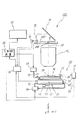
以下、本発明の第1の実施形態を図1〜図5に基づいて説明する。図1には、一実施形態に係る露光装置100の全体的な構成が概略的に示されている。この露光装置100は、いわゆるステップ・アンド・スキャン露光方式の走査型露光装置である。
【0022】
この露光装置100は、照明系10、レチクル(マスク)Rを保持するレチクルステージRST、投影光学系PL、基板としてのウエハWをXY平面内でXY2次元方向に駆動する基板ステージ装置30、及びこれらの制御系等を備えている。
【0023】
前記照明系10は、例えば特開平9−320956号公報に開示されように、光源ユニット、シャッタ、2次光源形成光学系、ビームスプリッタ、集光レンズ系、レチクルブラインド、及び結像レンズ系等(いずれも不図示)から構成され、図1のミラーMへ向けて照度分布のほぼ均一な露光用照明光を射出する。そして、この照明光がミラーMによってその光路が鉛直下方に折り曲げられ、レチクルR上の矩形(あるいは円弧状)の照明領域IARを均一な照度で照明する。
。
【0024】
前記レチクルステージRST上にはレチクルRが、例えば真空吸着により固定されている。また、このレチクルステージRSTは、不図示のレチクルベース上をリニアモータ等で構成されたレチクル駆動部(図示省略)により、所定の走査方向(ここではY軸方向とする)に指定された走査速度で駆動可能となっている。
【0025】
レチクルステージRST上にはレチクルレーザ干渉計(以下、「レチクル干渉計」という)16からのレーザビームを反射する移動鏡15が固定されており、レチクルステージRSTのステージ移動面内の位置はレチクル干渉計16によって、例えば0.5〜1nm程度の分解能で常時検出される。
【0026】
レチクル干渉計16からのレチクルステージRSTの位置情報はステージ制御系19及びこれを介して主制御装置20に送られ、ステージ制御系19では主制御装置20からの指示に応じてレチクルステージRSTの位置情報に基づいてレチクル駆動部(図示省略)を介してレチクルステージRSTを駆動する。
【0027】
前記投影光学系PLは、レチクルステージRSTの図1における下方に配置され、その光軸AX(照明光学系の光軸IXに一致)の方向がZ軸方向とされ、ここでは両側テレセントリックな光学配置となるように光軸AX方向に沿って所定間隔で配置された複数枚のレンズエレメントから成る屈折光学系が使用されている。この投影光学系PLは所定の投影倍率、例えば1/5(あるいは1/4)を有する縮小光学系である。このため、照明系10からの照明光によってレチクルRの照明領域IARが照明されると、このレチクルRを通過した照明光により、投影光学系PLを介してレチクルRの照明領域IAR内の回路パターンの縮小像(部分倒立像)が表面にフォトレジストが塗布されたウエハW上の照明領域IARに共役な露光領域IAに形成される。
【0028】
前記基板ステージ装置30は、ベース21と、このベース21の上面の上方に数μm程度のクリアランスを介して後述するエアスライダによって浮上支持された基板テーブル18と、この基板テーブル18をXY面内で2次元方向に駆動する駆動装置50とを備えている。駆動装置50としては、ここでは、ベース21の上部に設けられた(埋め込まれた)固定子60と、基板テーブル18の底部(ベース対向面側)に固定された可動子51とから成る平面モータが使用されている。また、可動子51とベース21と駆動装置50とによって平面モータ装置が構成されている。以下の説明においては、上記の駆動装置50を、便宜上、平面モータ50と呼ぶものとする。
【0029】
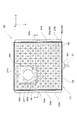
前記基板テーブル18上に、ウエハWが例えば真空吸着によって固定されている。また、この基板テーブル18上にはウエハレーザ干渉計(以下、「ウエハ干渉計」という)31からのレーザビームを反射する移動鏡27が固定され、外部に配置された前記ウエハ干渉計31により、基板テーブル18のXY面内での位置が例えば0.5〜1nm程度の分解能で常時検出されている。ここで、実際には、図2に示されるように、基板テーブル18上には走査方向であるY軸方向に直交する反射面を有する移動鏡27Yと非走査方向であるX軸方向に直交する反射面を有する移動鏡27Xとが設けられ、ウエハ干渉計31は走査方向に1軸、非走査方向には2軸設けられているが、図1ではこれらが代表的に移動鏡27、ウエハ干渉計31として示されている。基板テーブル18の位置情報(又は速度情報)はステージ制御系19及びこれを介して主制御装置20に送られ、ステージ制御系19では主制御装置20からの指示に応じて前記位置情報(又は速度情報)に基づいて平面モータ50を介して基板テーブル18のXY面内の移動を制御する。
【0030】
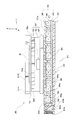
ここで、前記平面モータ50及びその近傍の構成部分を中心として、基板ステージ装置30の構成各部について、図2〜図4に基づいて更に詳述する。図2には、この基板ステージ装置30の平面図が示され、図3には、図2のA−A線断面図が一部省略して拡大して示されている。
【0031】
図2、図3に示されるように、基板テーブル18は、前記平面モータ50を構成する可動子51の上面(ベース21対向面と反対側の面)にボイスコイルモータ等を含む支持機構32a、32b、32cによって異なる3点で支持されており、XY面に対して傾斜及びZ軸方向の駆動が可能になっている。支持機構32a〜32cは、図1では図示が省略されているが、実際には不図示の駆動機構を介して図1のステージ制御系19によって独立に駆動制御される。
【0032】
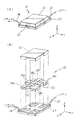
可動子51は、図4(A)の斜視図、図4(B)の分解斜視図に示されるように、平面視で田の字状の形状を有する一種の空気静圧軸受け装置であるエアスライダ57と、このエアスライダ57にその一部が上方から嵌合して一体化される平板状発磁体53と、この平板状発磁体53に上方から係合する磁性体材料から成る磁性体部材52とを備えている。この内、磁性体部材52と平板状発磁体53とによって磁石ユニットが構成される。磁性体部材52の上面に前記支持機構32a〜32cを介して基板テーブル18が設けられている。
【0033】
前記エアスライダ57は、その内部に加圧空気の供給路及びバキューム用の通路等が形成されている。そして、前記の加圧空気の供給路がチューブ33を介して空気ポンプ59(図1参照)に接続され、また、バキューム用の通路がチューブ34を介して不図示の真空ポンプに接続されている。一方、エアスライダ57の底面には、前記加圧空気の供給路に接続されたエアパッドと、前記のバキューム用の通路に接続されたエアポケットとがそれぞれ設けられている。
【0034】
このため、本実施形態では、可動子51及び基板テーブル18等の全体の自重と,磁石ユニットを構成する平板状発磁体53と後述する固定子ヨーク43との間の磁気的吸引力と,不図示の真空ポンプによる真空吸引力(与圧力)との総和に相当する下向きの力と、空気ポンプ59から供給されエアパッドを介してベース21の上面に向かって吹き出される加圧空気の圧力による上向きの力、すなわち可動子51底面とベース21上面との間の空気層の静圧(いわゆるすきま内圧力)とのバランスによって、その空気層の厚さ、すなわち軸受け隙間が所望の値に維持されるようになっている。このように、エアスライダ57は、一種の真空与圧型の空気静圧軸受けを構成しており、このエアスライダ57によって可動子51及び基板テーブル18等の全体がべース21の上面の上方に例えば5μm程度のクリアランスを介して浮上支持されている(図1、図3参照)。
【0035】
なお、本実施形態では、上記の如く、エアスライダ57に加圧空気の供給路とバキューム用の通路、及びこれらにそれぞれ接続されたエアパッド、エアポケットを設けたが、バキューム用の通路等は必ずしも設ける必要はない。
【0036】
前記平板状発磁体53は、図4(B)に示されるように、隣り合う磁極面の極性が互いに異なるように、2行2列のマトリクス状に配列された4個の推力発生磁石54a、54b、54c、54dと、隣り合う2個の推力発生磁石(54a,54b)、(54b,54c)、(54c,54d)、(54d,54a)が磁性体部材52側で形成する磁束経路中にそれぞれ配設された補間磁石55a、55b、55c、55dとから構成される。
【0037】
この平板状発磁体53を構成する推力発生磁石54a〜54dのそれぞれは、同一厚さ、同一形状の永久磁石から成り、正方形状の磁極面を有している。そして、これらの推力発生磁石54a〜54dは、X、Y両方向で隣り合う推力発生磁石相互間の間隙が所定幅となるように、同一平面上に2行2列のマトリクス状に配置されている。そして、X方向で隣り合う、推力発生磁石54a,54bと推力発生磁石54c,54dとでは、隣り合う磁極面の極性が互いに反対とされている。また、Y方向で隣り合う、推力発生磁石54a,54dと推力発生磁石54b,54cとでは、隣り合う磁極面の極性が互いに反対とされている。
【0038】
また、補間磁石55a〜55dのそれぞれは、同一厚さの長方形状の永久磁石から成り、平面視で見て、隣り合う2個の推力発生磁石(54a,54b)、(54b,54c)、(54c,54d)、(54d,54a)相互間の空隙をそれぞれ埋めるように、且つ側面視で見て推力発生磁石54a〜54dの上面が形成する仮想平面上に配置されている。これらの補間磁石55a〜55dは、推力発生磁石54a〜54dの磁極面と直交する磁極面を有し、これらの磁極面のそれぞれは、平面視で見て隣接する推力発生磁石54a〜54dの磁極面と反対の極性を有するように配置されている。
【0039】
前記ベース21は、図2、図3に示されるように、平面視で見て正方形状のベース本体22と、このベース本体22のY方向の両端に取り付けられた一対のジョイント取付部材23A、23Bとから構成されている。
【0040】
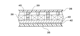
ベース本体22は、上面が開口した厚さの薄い中空の箱型の容器35と、この容器35の周壁の内部側に形成された第1の段部35aに上方から係合し、容器35の底壁から所定の空隙(例えば2mm程度の空隙)を隔てて該底壁に平行に配置された熱伝導率の高い、具体的には、熱伝導率が30〔W/m・K〕以上の磁性体材料から成る平板状の固定子ヨーク43と、容器35の周壁の上端(開口端)の内部側に形成された第2の段部35bに上方から係合して、開口部を閉塞するセラミック板36とを備えている。セラミック板36の可動子51対向側の面(上面)には、可動子51の移動面21aが形成されている。
【0041】
容器35とセラミック板36とによって形成されるベース21の内部空間は、固定子ヨーク43によって上下に区画され、その上側に真空室としての第1室41が形成され、その下側に第2室42が形成されている。この場合、固定子ヨーク43と移動面21aとは平行になっている。
【0042】
第1室41内には、図3に示されるように、セラミック板36との間に所定の空隙(例えば2mm程度の空隙)を介してかつ固定子ヨーク43に接した状態で、移動面21aに沿ってXY2次元方向に9行9列のマトリクス状に9×9=81個の電機子コイル38が配置されている(図2参照)。すなわち、本実施形態では、セラミック板36によって複数の電機子コイル38が収納される真空室としての第1室41を形成する第1の壁が構成され、固定子ヨーク43によって第1室42を形成する第2の壁が構成されている。電機子コイル38としては、図2に示されるように、中空の正方形状コイルが用いられている。
【0043】
本実施形態では、固定子ヨーク43と、電機子コイル38と、セラミック板36とによって、前述した平面モータ50の固定子60が構成されている。
【0044】
前記セラミック板36の移動面21aと反対側(下面側)には、図3に示されるように、所定間隔で断面円形の多数(ここでは145個)の突起部36aが形成されている。これらの突起部36aは、図2に示されるように、セラミック板36を容器35に組み付けた場合に、各電機子コイル38の中空部の中央に対応する位置に9×9=81個、隣接する4つの電機子コイル38相互間の空間に対応する位置に8×8=64個それぞれ設けられている。
【0045】
また、第1室41を形成するセラミック板36の前記各突起36aと固定子ヨーク43との間には、断熱材から成る変形防止部材としての柱39がそれぞれ設けられている。
【0046】
なお、図5に示されるように、セラミック板36を全くの平面板とし、この平面板36と固定子ヨーク43との間に、一部に断熱材40を含む柱状の変形防止部材39を設けても良い。
【0047】
図1に戻り、ベース21には、吸気管61を介して真空ポンプ62が接続されている。吸気管61は、図2に示されるベース21のX方向一側(+X側)に設けられた真空吸引ポート63に接続されており、この真空吸引ポート63は、第1室41に連通している。真空ポンプ62としては、ここでは、ターボ分子ポンプが用いられ、このターボ分子ポンプは、第1室41内を例えば1×10⁻⁶〔Torr〕以下の高度の真空状態とする真空引き能力を有する。
【0048】
また、前記一対のジョイント取付部材23A、23Bは、ベース本体22に溶接等により一体的に取り付けられている。これらのジョイント取付部材23A、23Bには、その長手方向の中央部にY方向を軸方向とする所定深さのねじ穴64a、64bがそれぞれ形成されている。
【0049】
一方のジョイント取付部材23Aには、図3に示されるように、ねじ穴64aに一端が連通する側面視でY方向一側から他側に向かって高さ方向(Z方向)の寸法が直線的に小さくなる断面直角三角形状の溝65aが形成されている。前記ベース本体22を構成する容器35のY方向一側の側壁には、前記第2室42と同一高さかつ同一のX方向幅寸法を有する断面が細長い矩形の貫通孔66が形成されており、この貫通孔66を介して前記溝65aと第2室42とが連通されている。容器35は左右対称の形状を有しており、貫通孔66は、図示が省略されているが、実際には容器35のY方向他側の側壁にも形成されている。
【0050】
また、前記溝65aの平面断面は、図2の平面図から明らかなように、Y方向一側から他側に向かってX方向の幅寸法が直線的に大きくなる二等辺三角形状となっている。すなわち、溝65aのXZ断面の断面積は、Y方向の位置に関係なく一定となっている。この場合、ねじ孔64aには、外周部に雄ねじが形成された不図示の冷媒供給用ジョイントの一端が取り付けられ、この冷媒供給用ジョイントの他端が図1の冷媒供給管92を介して温度制御装置としての冷却装置79内部に設けられた冷媒供給機に接続されている。従って、本実施形態では、上記の溝65aによって入り口側(ねじ孔64a側)から流入した流体としての液体冷媒をフィルム状に絞って、貫通孔66を介して第2室42に供給する断面積一定の絞りが形成されている。本実施形態では、ジョイント取付部材23Aに形成されたねじ穴64a(より正確には該ねじ穴64aに螺合される不図示の冷媒供給用ジョイントの内部通路)によって冷媒流入口が形成されている。
【0051】
他方のジョイント取付部材23Bは、上記一方のジョイント取付部材23Aと左右対称に溝65b及びねじ穴64bが形成され、容器35のY方向他側の側壁に形成された貫通孔66によって第2室42と溝部65bとが連通されている。ねじ穴64bには、外周部に雄ねじが形成された不図示の冷媒排出用ジョイントの一端側が取り付けられ、この冷媒排出用ジョイントの他端は図1の冷媒排出管93を介して冷却装置79内部に設けられた冷凍機に接続されている。この場合、ジョイント取付部材23Bに形成されたねじ穴64b(より正確には該ねじ穴64bに螺合される不図示の冷媒排出用ジョイントの内部通路)によって冷媒流出口が形成されている。
【0052】
これまでの説明から明らかなように、本実施形態では、冷媒供給用ジョイントを介してベース21(第2室42)内に供給された液体冷媒がベース21内部を冷却した後、冷媒排出用ジョイントを介して冷却装置79に戻され、そこで冷却されて再びベース21内に供給され、このようにして液体冷媒が循環使用されるようになっている。液体冷媒としては、例えば水あるいはフロリナート(製造元:住友スリーエム(株)、フッ素系不活性液体)等が使用され、この液体冷媒はベース雰囲気温度よりも低温に温度制御された状態でベース21内に供給される。また、冷媒供給用ジョイントから冷媒排出用ジョイントに至るベース21内の冷媒通路(65a、66、42、66、65b)の断面積は該通路全長に渡って一定となっている。
【0053】
更に、本実施形態では、固定子ヨーク43の第2室42側の壁面(下面)は、その表面が粗く形成されている。これは、固定子ヨーク43の下面に沿って流れる液体冷媒の流れを積極的に乱して第2室42内の液体冷媒の流れ(特に固定子ヨーク43の下面の境界層)をそのレイノルズ数が臨界レイノルズ数より大きい乱流にするためである。
【0054】
次に、前述したステージ装置30を含む露光装置100における露光動作の流れについて簡単に説明する。
【0055】
まず、主制御装置20の管理の下、不図示のレチクルローダ、ウエハローダによってレチクルロード、ウエハロードが行われ、また、不図示のレチクル顕微鏡、基板テーブル18上の不図示の基準マーク板、不図示のアラインメント検出系を用いてレチクルアラインメント、ベースライン計測等の準備作業が所定の手順に従って行われる。
【0056】
その後、主制御装置20により、不図示のアラインメント検出系を用いてEGA(エンハンスト・グローバル・アラインメント)等のアラインメント計測が実行される。このような動作において、ウエハWの移動が必要な場合には、主制御装置20がステージ制御系19を介して、推力発生磁石54a〜54dに対向する電機子コイル38に供給する電流値、及び電流方向の少なくとも一方を制御することにより、可動子51と一体的にウエハWを保持する基板テーブル18を所望の方向に移動させる。アライメント計測の終了後、以下のようにしてステップ・アンド・スキャン方式の露光動作が行われる。
【0057】
この露光動作にあたって、まず、ウエハWのXY位置が、ウエハW上の最初のショット領域(ファースト・ショット)の露光のための走査開始位置となるように、基板テーブル18が移動される。同時に、レチクルRのXY位置が、走査開始位置となるように、レチクルステージ18が移動される。そして、主制御装置20からの指示に基づき、ステージ制御系19が、レチクル干渉計16によって計測されたレチクルRのXY位置情報、ウエハ干渉計31によって計測されたウエハWのXY位置情報に基づき、不図示のレチクル駆動部及び平面モータ50を介してレチクルRとウエハWとを同期移動させることにより、走査露光が行われる。このウエハWの移動は、主制御装置20によりステージ制御系19を介して、推力発生磁石54a〜54dに対向する電機子コイル38に供給する電流値、及び電流方向の少なくとも一方を制御することにより行われる。
【0058】
このようにして、1つのショット領域に対するレチクルパターンの転写が終了すると、基板テーブル18が1ショット領域分だけステッピングされて、次のショット領域に対する走査露光が行われる。このようにして、ステッピングと走査露光とが順次繰り返され、ウエハW上に必要なショット数のパターンが転写される。
【0059】
ここで、上記のアライメント時や走査露光時においては、平面モータ50の固定子60を構成する各電機子コイル38には適宜電流が供給されるので、この電機子コイル38が発熱するが、この熱が移動面21a側へ伝わるのを以下のようにして効果的に抑制(あるいは防止)している。
【0060】
まず、複数の電機子コイル38が収納されたベース21内の第1室41内は真空ポンプ62によって真空引きされて高度の真空状態となっている。従って、第1室41を形成する移動面21a側のセラミック板36と固定子ヨーク43上に配置された電機子コイル38との間には高度の真空状態の空隙が存在するため、電機子コイル38から移動面21a側への伝熱は殆ど熱放射のみによって行われる。すなわち、上記の電機子コイル38上部の空隙が一種の断熱層として機能して移動面側への伝熱を効果的に抑制している。
【0061】
この場合、上記の断熱層としての真空層は、その真空度が高い程、その断熱(伝熱抑制効果)は高くなる。本実施形態では1×10⁻⁶〔Torr〕という高度の真空状態を実現できるので、電機子コイル38の周囲に空気が殆ど存在せず、空気を熱伝達媒体としての熱伝導、熱伝達を極めて小さく抑えることができ、その伝熱抑制効果は極めて高くなっている。
【0062】
なお、この場合、上記の高真空状態をベース本体22内に設定しても、セラミック板36と固定子ヨーク43との間に多数の柱39がほぼ均等な間隔でベース本体の全面に渡って配置されているので、外気圧によってセラミック板36等が変形することがなく、セラミック板36上面の移動面21aを平坦に維持できる。
【0063】
また、上記のようにセラミック板36と固定子ヨーク43との間に多数の柱39を設けた場合、電機子コイル38で発生した熱が固定子ヨーク43及びそれらの柱39を介してセラミック板36側、すなわち移動面21a側に伝達するおそれがあるが、本実施形態では柱39の少なくとも一部が断熱材により形成されているため、該柱39を媒体としての熱伝導もほぼ阻止できる。
【0064】
また、電機子コイル38が接触する固定子ヨーク43が熱伝導率の高い磁性体材料により形成されていることから、該固定子ヨーク43が磁気回路構成部材として機能するのみでなく、電機子コイル38で発生した熱を効率良くベース本体22の移動面21aと反対側の面に伝導する。
【0065】
また、ベース21内の固定子ヨーク43の移動面21aと反対側には、固定子ヨーク43を介して真空室41に接する第2室42が設けられ、この第2室42内がベース21のY方向一側に接続された冷媒供給用ジョイントとベース21のY方向他側に接続された冷媒排出用ジョイントに連通しており、冷却装置79によって冷媒供給用ジョイントを介して第2室42内にベース雰囲気より低温に温度制御された液体冷媒(流体)が供給されている。このため、固定子ヨーク43と液体冷媒との間で熱交換が行われ、電機子コイル38を下面側から効率的に冷却することができ、これによって各電機子コイル38の温度上昇そのものを抑制することができる。
【0066】
また、本実施形態では、ベース21内に冷媒供給用ジョイントを介してY方向一側から供給された液体冷媒をY方向他側の冷媒排出用ジョイントを介して排出する断面積一定の冷媒通路が設けられていることから、冷媒供給用ジョイントを介してベース内に流入した液体冷媒は、フィルム状に広がって各電機子コイルの下方に均一に行き渡り、平面上に展開された複数の電機子コイルが均一に除熱される。
【0067】
さらに、固定子ヨーク43の第2室42側の壁面(下面)は、その表面が粗く形成され凸凹になっているので、固定子ヨーク43の下面を沿って流れる液体冷媒との間の流れのイノルズ数が臨界レイノルズ数より大きくなって乱流となっている。流路内流れが乱流の場合、固体−液体間熱伝達係数は層流の場合に比べて大きく(十〜数十倍もあり)、さらに流体的にも熱的にも早く発達流となるため各電機子コイル38の除熱が迅速かつ均一となる。かかる意味で、固定子ヨーク43の下面に所定間隔で突起を設けても良い。
【0068】
以上により、電機子コイル38全面より放出される熱が、移動面側に伝達されるのを効果的に抑制することができ、周囲環境に与える熱的影響を可能な限り抑制することができる。また、本実施形態では、冷却装置79から冷媒供給管92冷媒供給用ジョイントを介してベース21内に液体冷媒が供給され、この液体冷媒はベース21内の冷媒通路を通って各電機子コイル38を下面側から冷却し、この冷却により温度が上昇した液体冷媒は冷媒排出用ジョイント及び冷媒排出管93を介して冷却装置79に戻り、ここで冷却されて、再度ベース21内に供給され各電機子コイル38を冷却する。すなわち、このようにして液体冷媒が循環使用されるため、常にほぼ一定量の液体冷媒を用いて電機子コイル38を冷却することができ、経済的である。
【0069】
以上説明したように、本実施形態によると、装置環境への熱的影響を最小限に抑えられることから、ウエハテーブル18の位置を計測する干渉計31の干渉計ビームの空気揺らぎ等も殆ど問題とならず、精密なウエハの位置決め及び位置制御が可能になる。従って、本実施形態の露光装置100によると、電磁力駆動方式の平面モータ50を備えた基板ステージ装置30によりウエハWを精度よく高速に位置制御することができ、スループットを向上しつつ、高い露光精度で露光することが可能になる。
【0070】
なお、上記実施形態で説明したベース21の構成は一例であって、本発明がこれに限定されるものではない。
【0071】
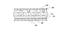
例えば、上記実施形態では、セラミック板36と固定子ヨーク43との間に全部又は一部が断熱材で形成された柱39を設ける場合を説明したが、これに代えて、図6に示されるように、固定子ヨーク43との接触面の面積が他の部分の断面積より小さくなるように、固定子ヨーク43側の端部(下端部)をテーパ状に形成した柱80を変形防止部材として設けても良い。該柱80は、固定子ヨーク43側から熱が伝わり難い形状となっているので、必ずしも断熱材で形成する必要はない。
【0072】
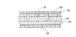
また、上記実施形態では、電機子コイル38とセラミック板43との間の空隙には、何も介在物を配置しない場合を説明したが、該空隙が真空状態であるといっても空気が僅かながら存在する。このため、その空気を熱伝達媒体として熱伝導、熱伝達現象が生じ得る。かかる現象を更に抑制するため、図7に示されるように、電機子コイル38とセラミック板43との間の空隙に、断熱材81を介在させても良い。
【0073】
なお、上記実施形態では、第1室41を形成する第1の壁をその可動子51対向面に移動面21aが形成されたセラミック板36で構成する場合について説明したが、第1の壁と移動面形成部材とを別部材としても良い。この場合は、第1の壁及び移動面形成部材の双方をセラミック等の非磁性材料によって形成する必要がある。
【0074】
また、上記実施形態では、固定子ヨーク43の下側に流体通路としての冷媒通路を構成する第2室42を設ける場合について説明したが、本発明がこれに限定されるものではない。すなわち、電機子コイル38とセラミック板36との間に所定の空隙が存在し、第1室41内が真空ポンプ62によって真空吸引されていれば足り、第2室42及び該第2室42内への冷媒供給のためのジョイント取り付け部材等をベース21に必ずしも設ける必要はない。かかる場合には、容器35(ベース21)の電機子コイル38が接触配置される第2の壁を鉄等の磁性材料によって形成することにより、該第2の壁が磁気回路構成部材として機能するとともに、該第2の壁と外気との間で熱交換が行われ、電機子コイル38下面が冷却される。この場合、第2の壁は、熱伝導率の高い磁性体材料によって形成することが望ましい。
【0075】
《第2の実施形態》
次に、本発明の第2の実施形態を図8に基づいて説明する。この第2の実施形態は、ベース本体22の内部構成が僅かに異なるのみで、その他の部分の構成は前述した第1の実施形態と同一であるから、重複部分については、極力その説明を簡略化し若しくは省略するとともに、同一若しくは同等の構成部分については同一の符号を用いるものとする。
【0076】
図8(A)には、第2の実施形態に係るベース本体22の断面図が一部省略して示されている。本第2の実施形態では、ベース本体22内の真空室41内には、電機子コイル38が固定子ヨーク43に接して移動面21aに沿って所定間隔で2次元方向に配置されている点は、前述した第1の実施形態と同様であるが、真空室41の移動面21a側が、電機子コイル38の移動面側に接して配置された非磁性体材料から成る薄板82によって規定され、この真空室41の移動面21a側に流体通路としての冷媒通路99が設けられている点に特徴を有する。
【0077】
この冷媒通路99内には、図1の冷却装置79からの液体冷媒が順環供給されている。その他の部分の構成等は、第1の実施形態と同一である。
【0078】
このようにして構成された本第2の実施形態によると、前述した第1の実施形態と同等の効果を得られる。すなわち、電機子コイル38はベース内部の真空室41内に配置され、その真空室41を形成する移動面21a側に冷媒通路99が設けられていることから、真空室41内における真空部(具体的には、各電機子コイル38の中空部と柱80との間、及び隣接する電機子コイル38相互間の中央の空隙と柱80との間)においては電機子コイル38からの伝熱は殆ど熱放射のみによって行われ、また、真空室41内の移動面21a側に伝わった熱は冷媒通路99内を流れるベース雰囲気温度より低温に温調された液体冷媒との熱交換によって除熱される。従って、周囲環境への熱的影響を効果的に抑制することができる。
【0079】
また、本第2の実施形態の場合は、薄板82に沿って流れる液体冷媒の流れの境界層が層流(臨界レイノルズ数以下)となるように、薄板82の表面を平坦度良く仕上げることが望ましい。このようにすると、薄板82とセラミック板36との間の流れが図8(B)に示されるように高温部と低温部との境界が存在するような流れとなり、電機子コイル38の熱がセラミック板36に伝達されるのをほぼ確実に防止することができる。
【0080】
なお、上記第1、第2の実施形態では、流体としての液体冷媒を循環使用する場合について説明したが、本発明がこれに限定されるものではない。すなわち、流体しては液体に限らず気体を用いても良く、また、流体として例えば空気等を用いる場合には、必ずしも循環使用する必要はない。
【0081】
また、本発明に係る露光装置は、上記実施形態でも説明したように、基板を精度よく高速に位置制御することができ、スループットを向上しつつ高い露光精度で露光が可能になるように、該装置を構成する各構成要素が電気的、機械的又は光学的に連結されて組み上げられる。
【0082】
なお、上記実施形態では、本発明に係る平面モータ装置が走査型のDUV露光装置の基板ステージ装置に適用された場合について説明したが、これに限らず、ステッパ等の静止型露光装置は勿論、電子線露光装置等の荷電粒子線露光装置、波長5〜15nm程度の軟X線領域の光を露光光とし用いるいわゆるEUVL等の露光装置、露光装置以外の装置、例えば検査装置や基板搬送装置等にも好適に適用できるものである。
【0083】
なお、本発明の真空室内に電機子コイルを配置するという技術的思想は、リニアモータにも応用可能である。
【0084】
【発明の効果】
以上説明したように、請求項1〜20に記載の各発明によれば、周囲環境への熱的影響を抑制できるという効果がある。
【0085】
また、請求項21に記載の発明によれば、高スループットを維持しつつ高精度な露光が可能になるという効果がある。
【図面の簡単な説明】
【図1】第1の実施形態に係る露光装置の概略構成を示す図である。
【図2】図1の基板ステージ装置を示す平面図である。
【図3】図2のA−A線断面図である。
【図4】(A)は図1の基板ステージ装置を構成する平面モータの可動子を示す斜視図、(B)は(A)の可動子の分解斜視図である。
【図5】ベース本体を構成する柱の変形例を説明するためのベース本体の断面図である。
【図6】ベース本体を構成する柱の他の変形例を説明するためのベース本体の断面図である。
【図7】ベース本体のその他の変形例を説明するためのベース本体の断面図である。
【図8】(A)は第2の実施形態に係るベース本体の断面図、(B)は真空室上部側の冷媒通路内の液体冷媒の流れの状態を示す図である。
【符号の説明】
21a…移動面、30…基板ステージ装置、41…真空室、21…ベース(平面モータ装置の一部)、36…セラミック板(第1の壁)、38…電機子コイル、39…柱(変形防止部材)、42…第2室(流体通路の一部)、43…固定子ヨーク(第2の壁)、50…平面モータ(平面モータ装置の一部)、51…可動子(平面モータ装置の一部)、52…磁性体部材(磁石ユニットの一部)、53…平板状発磁体(磁石ユニットの一部)、54a,54b,54c,54d…推力発生磁石(磁石)、65a,65b…溝部(流体通路の一部)、66…貫通孔(流体通路の一部)、79…冷却装置(温度制御装置)、100…露光装置、W…ウエハ(基板)。[0001]
BACKGROUND OF THE INVENTION
The present invention relates to a planar motor device and an exposure apparatus, and more specifically, a planar motor device that drives a mover including a magnet unit in a two-dimensional direction by electromagnetic force, and an exposure that uses the planar motor device for a substrate stage device. Relates to the device.
[0002]
[Prior art]
Conventionally, in a lithography process for manufacturing a semiconductor element, a liquid crystal display element or the like, a resist or the like is applied to a pattern formed on a mask or a reticle (hereinafter, collectively referred to as “reticle”) via a projection optical system. An exposure apparatus that transfers onto a substrate such as a wafer or a glass plate is used.
[0003]
In this exposure apparatus, since the wafer needs to be positioned at the exposure position with high accuracy, the wafer is held on the wafer holder by vacuum suction or the like, and the wafer holder is fixed on the wafer table.
[0004]
Recently, wafers have been placed in order to position the wafers at high speed and with high accuracy without being affected by the accuracy of the mechanical guide surface, etc., and to avoid mechanical friction and extend the life. A stage apparatus that positions a wafer by driving a table in a two-dimensional direction without contact has been developed. As a driving source of such a non-contact driving stage device, a planar motor having a structure in which two axes of variable magnetic resistance driving type linear pulse motors are connected is known.
[0005]
At present, a variable magnetoresistive drive type planar motor is mainly composed of two variable magnetoresistive drive type linear pulse motors such as a soy motor. This variable magnetoresistive drive type linear pulse motor includes, for example, a stator composed of a plate-like magnetic body in which uneven teeth are formed at equal intervals along the longitudinal direction, and the unevenness of the stator. The armature coil is provided with a plurality of armature coils that are connected to each other through permanent magnets. Then, the mover is driven by using a force generated to minimize the magnetic resistance between the stator and the mover at each time point. That is, the mover is stepped by adjusting and controlling the current value and phase of the pulse current supplied to each armature coil.
[0006]
[Problems to be solved by the invention]
In order to achieve high-speed positioning by using the above-described variable magnetoresistive driving type planar motor for precise positioning, it is necessary to obtain a large driving force. A large current must be passed. Therefore, heat generation of the armature coil becomes a big problem.
[0007]
In addition, a planar motor using Lorentz electromagnetic force driving in which a linear motor is developed in a two-dimensional direction has been developed (see, for example, US Pat. No. 5,196,745). Such a Lorentz electromagnetic force type planar motor is said to be promising as a stage drive source in the future because it is excellent in controllability, thrust linearity, and positioning. However, even in such a Lorentz electromagnetic force driven planar motor, in order to obtain a large thrust, a large current must flow through the armature coil, and the armature coil becomes a heat source.
[0008]
Therefore, when considering a precise positioning device environment, a cooling design is indispensable for realizing a planar motor that reduces thermal influence.
[0009]
The present invention has been made under such circumstances, and a first object thereof is to provide a planar motor device capable of suppressing thermal influence on the surrounding environment.
[0010]
A second object of the present invention is to provide an exposure apparatus that can perform high-precision exposure while maintaining high throughput.
[0011]
[Means for Solving the Problems]
Heat is transferred between objects mainly by heat conduction, heat transfer, and heat radiation (radiation), and all change due to a temperature difference between the objects. Among them, heat conduction is heat transfer by molecular vibration due to heat and movement of electrons with energy, and heat transfer is heat transfer by convection between the solid surface and the fluid, so both require a heat medium. Yes, it can hardly occur in vacuum. On the other hand, since heat radiation is heat transfer by electromagnetic waves emanating from an object, it occurs even in a vacuum where no heat transfer medium exists, but the amount of heat transfer is small compared to heat conduction and heat transfer.
[0012]
The present invention pays attention to this point and adopts the following configuration.
[0013]
The first planar motor device according to the present invention includes at least one magnet (54a to 54d) and a magnet unit (52, 53) that moves in a two-dimensional direction along a predetermined moving surface (21a); The moving surface is formed on the side facing the magnet unit, and a base (21) having a vacuum chamber (41) capable of maintaining a vacuum state therein; on the moving surface side forming the vacuum chamber A plurality of armature coils (38) disposed in a two-dimensional direction along the moving surface in the vacuum chamber through a predetermined gap between the first wall (36) and the first wall (36).
[0014]
According to this, when a current is supplied to the armature coil facing the magnet of the magnet unit, the magnet unit is driven along the moving surface by the electromagnetic force. When the magnet unit is continuously driven in a certain direction, a current is supplied to the armature coil facing the magnet for each moving position of the magnet unit. Thereby, the armature coil supplied with each current generates heat. In this case, the armature coil is housed in a vacuum chamber inside the base, and 2 in the vacuum chamber along the moving surface through a predetermined gap between the armature coil and the first wall on the moving surface side forming the vacuum chamber. It is arranged in the dimension direction. For this reason, since heat transfer from the armature coil to the moving surface side is performed almost only by heat radiation, the thermal influence on the surrounding environment can be effectively suppressed.
[0015]
In this case, since air exists even if the vacuum chamber is in a vacuum state, heat conduction and heat transfer cannot be completely eliminated, and the degree depends on the degree of vacuum. In this sense, a higher degree of vacuum is desirable, but if the degree of vacuum is higher than a certain level, the base may be deformed due to a pressure difference between the atmospheric pressure and the vacuum chamber. Accordingly, in order to prevent such deformation, the vacuum state is caused between the first wall (36) forming the vacuum chamber (41) and the second wall (43) facing the first wall. It is desirable to provide a deformation preventing member (39) for preventing deformation of the base. However, in such a case, the heat generated in the armature coil is transmitted by heat conduction to the first wall side, that is, the moving surface side via the second wall and the deformation preventing member. Therefore, in order to suppress or prevent this heat conduction, at least a part of the deformation prevention member is formed of a heat insulating material, or the deformation prevention member has an area of a contact surface with the second wall to prevent the deformation. It is desirable to form a shape that is smaller than the cross-sectional area of the other part of the member.
[0016]
In the above-described case, the base (21) has a fluid passage (65a, 66, 42) that contacts the vacuum chamber via the second wall (43) on the opposite side of the moving surface of the vacuum chamber (41). 66, 65b) is more desirable. In such a case, heat exchange is performed between the fluid in the fluid passage and the second wall, and the armature coil is cooled from the second wall side (the side opposite to the moving surface). In this case, a temperature control device (79) for controlling the temperature of the fluid flowing through the fluid passage may be provided. In this temperature control device, it is sufficient to control the temperature of the fluid to at least a temperature lower than the temperature of the second wall when the armature coil generates heat, but the fluid is controlled to a temperature lower than the ambient temperature of the base. Also good. In such a case, the armature coil can be efficiently cooled from the side opposite to the moving surface.
[0017]
The second planar motor device according to the present invention includes at least one magnet (54a to 54d) and a magnet unit (52, 53) that moves in a two-dimensional direction along a predetermined moving surface (21a); A vacuum chamber (41) in which the moving surface is formed on the side facing the magnet unit and in which a vacuum state can be maintained;Fluid passes throughA base (21) having a fluid passage; and a plurality of armature coils (38) arranged in a two-dimensional direction at predetermined intervals along the moving surface in the vacuum chamber.
[0018]
According to this, when a current is supplied to the armature coil facing the magnet of the magnet unit, the magnet unit is driven along the moving surface by the electromagnetic force. When the magnet unit is continuously driven in a certain direction, a current is supplied to the armature coil facing the magnet for each moving position of the magnet unit. Thereby, the armature coil supplied with each current generates heat.In this case, since the armature coil is disposed in the vacuum chamber inside the base, heat transfer from the armature coil is performed only by heat radiation, and the heat transferred from the vacuum chamber is the fluid in the fluid passage. The heat is removed by heat exchange.Therefore, the thermal influence on the surrounding environment can be effectively suppressed. In this case, it is desirable that the fluid in the fluid passage is cooler than the base atmosphere.
A drive device according to the present invention includes at least one magnet and a magnet unit (52, 53) that moves along a predetermined moving surface; and the moving surface is formed on a side facing the magnet unit, A base (21) having a vacuum chamber (41) capable of maintaining a vacuum state therein and a fluid passage through which a fluid passes; a plurality of chambers disposed at predetermined intervals along the moving surface in the vacuum chamber; And an armature coil (38). According to this, since the armature coil is disposed in the vacuum chamber inside the base, heat transfer from the armature coil is performed almost only by heat radiation, and the heat transferred from the vacuum chamber is in the fluid passage. Heat is removed by heat exchange with the fluid.
[0019]
An exposure apparatus according to the present invention is an exposure apparatus for transferring a predetermined pattern onto a substrate, and the substrate stage device for driving the substrate is provided with any one of the first and second planar motor devices according to the present invention. It is used.
[0020]
According to this, since the planar motor device according to the present invention is used for the substrate stage, the substrate can be driven in a two-dimensional manner by non-contact and electromagnetic force, and the substrate is heated by the armature coil. Since the thermal influence on the side can be effectively reduced, the air fluctuation of the interferometer beam for measuring the position of the substrate can be suppressed. Therefore, it is possible to control the position of the substrate with high speed and high accuracy, and as a result, it is possible to perform exposure with high exposure accuracy while improving throughput.
[0021]
DETAILED DESCRIPTION OF THE INVENTION
A first embodiment of the present invention will be described below with reference to FIGS. FIG. 1 schematically shows an overall configuration of an
[0022]
The
[0023]
The
.
[0024]
On reticle stage RST, reticle R is fixed, for example, by vacuum suction. Further, this reticle stage RST has a scanning speed designated in a predetermined scanning direction (here, the Y-axis direction) by a reticle driving unit (not shown) constituted by a linear motor or the like on a reticle base (not shown). It can be driven by.
[0025]
A
[0026]
Position information of reticle stage RST from
[0027]
The projection optical system PL is disposed below the reticle stage RST in FIG. 1, and the direction of the optical axis AX (coincidence with the optical axis IX of the illumination optical system) is the Z-axis direction. A refractive optical system composed of a plurality of lens elements arranged at a predetermined interval along the optical axis AX direction is used. The projection optical system PL is a reduction optical system having a predetermined projection magnification, for example, 1/5 (or 1/4). For this reason, when the illumination area IAR of the reticle R is illuminated by the illumination light from the
[0028]
The
[0029]
A wafer W is fixed on the substrate table 18 by, for example, vacuum suction. A
[0030]
Here, the constituent parts of the
[0031]
As shown in FIGS. 2 and 3, the substrate table 18 includes a
[0032]
As shown in the perspective view of FIG. 4 (A) and the exploded perspective view of FIG. 4 (B), the
[0033]
The
[0034]
For this reason, in the present embodiment, the entire weight of the
[0035]
In the present embodiment, as described above, the
[0036]
As shown in FIG. 4B, the flat plate-
[0037]
Each of the
[0038]
Each of the interpolation magnets 55a to 55d is made of a rectangular permanent magnet having the same thickness. When viewed in a plan view, the two adjacent thrust generating magnets (54a, 54b), (54b, 54c), ( 54c, 54d) and (54d, 54a) are arranged on a virtual plane formed by the upper surfaces of the
[0039]
As shown in FIGS. 2 and 3, the
[0040]
The
[0041]
An internal space of the base 21 formed by the
[0042]
In the
[0043]
In the present embodiment, the
[0044]
On the opposite side (lower surface side) of the
[0045]
Further, between the
[0046]
As shown in FIG. 5, the
[0047]
Returning to FIG. 1, a
[0048]
The pair of
[0049]
As shown in FIG. 3, one joint mounting member 23 </ b> A has a linear dimension in the height direction (Z direction) from one side in the Y direction to the other side in a side view where one end communicates with the
[0050]
Further, as is apparent from the plan view of FIG. 2, the planar cross section of the
[0051]
The other joint mounting
[0052]
As is apparent from the above description, in this embodiment, the liquid refrigerant supplied into the base 21 (second chamber 42) via the refrigerant supply joint cools the inside of the
[0053]
Furthermore, in this embodiment, the wall surface (lower surface) of the
[0054]
Next, the flow of the exposure operation in the
[0055]
First, under the control of the
[0056]
After that, the
[0057]
In this exposure operation, first, the substrate table 18 is moved so that the XY position of the wafer W becomes the scanning start position for the exposure of the first shot region (first shot) on the wafer W. At the same time, the
[0058]
In this way, when the transfer of the reticle pattern for one shot area is completed, the substrate table 18 is stepped by one shot area, and scanning exposure is performed for the next shot area. In this way, stepping and scanning exposure are sequentially repeated, and a pattern having the required number of shots is transferred onto the wafer W.
[0059]
Here, at the time of the alignment and the scanning exposure, since current is appropriately supplied to each
[0060]
First, the
[0061]
In this case, the higher the degree of vacuum of the vacuum layer as the heat insulating layer, the higher the heat insulation (heat transfer suppression effect). In this embodiment, 1 × 10⁻⁶Since a high vacuum state of [Torr] can be realized, there is almost no air around the
[0062]
In this case, even if the high vacuum state is set in the
[0063]
Further, when a large number of
[0064]
In addition, since the
[0065]
A
[0066]
Further, in the present embodiment, there is provided a refrigerant passage having a constant cross-sectional area for discharging the liquid refrigerant supplied from one side in the Y direction through the refrigerant supply joint into the base 21 through the refrigerant discharge joint on the other side in the Y direction. Therefore, the liquid refrigerant that has flowed into the base via the refrigerant supply joint spreads in a film shape, spreads uniformly under each armature coil, and a plurality of armature coils developed on a plane. Is uniformly removed.
[0067]
Furthermore, since the wall surface (lower surface) of the
[0068]
As described above, the heat released from the entire surface of the
[0069]
As described above, according to this embodiment, since the thermal influence on the apparatus environment can be minimized, the air fluctuation of the interferometer beam of the
[0070]
In addition, the structure of the base 21 demonstrated by the said embodiment is an example, Comprising: This invention is not limited to this.
[0071]
For example, in the above-described embodiment, the case where the
[0072]
In the above embodiment, the case where no inclusion is disposed in the gap between the
[0073]
In the above embodiment, the case where the first wall forming the
[0074]
Moreover, although the said embodiment demonstrated the case where the
[0075]
<< Second Embodiment >>
Next, a second embodiment of the present invention will be described with reference to FIG. In the second embodiment, only the internal configuration of the
[0076]
FIG. 8A is a partially omitted cross-sectional view of the
[0077]
In the
[0078]
According to the second embodiment configured as described above, an effect equivalent to that of the first embodiment described above can be obtained. That is, the
[0079]
In the case of the second embodiment, the surface of the
[0080]
In addition, although the said 1st, 2nd embodiment demonstrated the case where the liquid refrigerant | coolant as a fluid was circulated and used, this invention is not limited to this. That is, the fluid is not limited to a liquid, and a gas may be used, and when air is used as the fluid, it is not always necessary to circulate.
[0081]
Further, as described in the above embodiment, the exposure apparatus according to the present invention can control the position of the substrate with high accuracy and high speed, and can perform exposure with high exposure accuracy while improving throughput. Each component constituting the apparatus is assembled by being electrically, mechanically or optically connected.
[0082]
In the above embodiment, the case where the planar motor device according to the present invention is applied to the substrate stage device of the scanning type DUV exposure device is described. However, the present invention is not limited to this, and of course, a stationary exposure device such as a stepper, Charged particle beam exposure apparatuses such as electron beam exposure apparatuses, exposure apparatuses such as so-called EUVL that use light in the soft X-ray region having a wavelength of about 5 to 15 nm as exposure light, apparatuses other than exposure apparatuses, such as inspection apparatuses and substrate transport apparatuses It can be suitably applied to.
[0083]
The technical idea of arranging the armature coil in the vacuum chamber of the present invention can also be applied to a linear motor.
[0084]
【The invention's effect】
As described above, claims 1 to20According to each invention described in, there is an effect that the thermal influence on the surrounding environment can be suppressed.
[0085]
Claims21According to the invention described in (1), there is an effect that high-precision exposure is possible while maintaining high throughput.
[Brief description of the drawings]
FIG. 1 is a view showing a schematic configuration of an exposure apparatus according to a first embodiment.
2 is a plan view showing the substrate stage apparatus of FIG. 1. FIG.
FIG. 3 is a cross-sectional view taken along line AA in FIG.
4A is a perspective view showing a movable element of a planar motor constituting the substrate stage apparatus of FIG. 1, and FIG. 4B is an exploded perspective view of the movable element of FIG.
FIG. 5 is a cross-sectional view of a base body for explaining a modified example of a pillar constituting the base body.
FIG. 6 is a cross-sectional view of a base body for explaining another modified example of the pillar constituting the base body.
FIG. 7 is a cross-sectional view of a base body for explaining another modification of the base body.
8A is a cross-sectional view of a base body according to a second embodiment, and FIG. 8B is a diagram showing a state of a flow of liquid refrigerant in a refrigerant passage on the upper side of a vacuum chamber.
[Explanation of symbols]
21a ... Moving surface, 30 ... Substrate stage device, 41 ... Vacuum chamber, 21 ... Base (part of flat motor device), 36 ... Ceramic plate (first wall), 38 ... Armature coil, 39 ... Pillar (deformation) Prevention member), 42 ... second chamber (part of fluid passage), 43 ... stator yoke (second wall), 50 ... planar motor (part of planar motor device), 51 ... mover (planar motor device) ), 52... Magnetic member (part of the magnet unit), 53... Flat plate generator (part of the magnet unit), 54 a, 54 b, 54 c, 54 d, thrust generating magnet (magnet), 65 a, 65 b ... Groove (part of fluid passage), 66 through hole (part of fluid passage), 79 cooling device (temperature control device), 100 exposure device, and W wafer (substrate).
Claims (21)
前記磁石ユニットと対向する側に前記移動面が形成されるとともに、その内部に真空状態を保持可能な真空室を有するベースと;
前記真空室を形成する前記移動面側の第1の壁との間に所定の空隙を介してかつ前記真空室内に前記移動面に沿って2次元方向に配置された複数の電機子コイルと;
を備える平面モータ装置。A magnet unit having at least one magnet and moving in a two-dimensional direction along a predetermined moving surface;
A base having a vacuum chamber in which the moving surface is formed on a side facing the magnet unit and in which a vacuum state can be maintained;
A plurality of armature coils arranged in a two-dimensional direction in the vacuum chamber along the moving surface through a predetermined gap between the first wall on the moving surface side forming the vacuum chamber;
A planar motor device comprising:
前記磁石ユニットと対向する側に前記移動面が形成され、その内部に真空状態を保持可能な真空室と流体が通過する流体通路とを有するベースと;
前記真空室内に前記移動面に沿って所定間隔で2次元方向に配置された複数の電機子コイルとを備える平面モータ装置。A magnet unit having at least one magnet and moving in a two-dimensional direction along a predetermined moving surface;
A base having a moving chamber formed on the side facing the magnet unit and having a vacuum chamber capable of maintaining a vacuum state therein and a fluid passage through which a fluid passes ;
A planar motor device comprising a plurality of armature coils arranged in a two-dimensional direction at predetermined intervals along the moving surface in the vacuum chamber.
前記磁石ユニットと対向する側に前記移動面が形成され、その内部に真空状態を保持可能な真空室とその内部に流体が通過する流体通路とを有するベースと; A base having a moving chamber formed on the side facing the magnet unit and having a vacuum chamber capable of maintaining a vacuum state therein and a fluid passage through which fluid passes;
前記真空室内に前記移動面に沿って所定間隔で配置された複数の電機子コイルとを備えることを特徴とする駆動装置。 A drive device comprising: a plurality of armature coils arranged at predetermined intervals along the moving surface in the vacuum chamber.
前記基板を駆動する基板ステージ装置に請求項1〜16のいずれか一項に記載の平面モータ装置を用いたことを特徴とする露光装置。An exposure apparatus for transferring a predetermined pattern onto a substrate,
An exposure apparatus using the planar motor device according to any one of claims 1 to 16 as a substrate stage device for driving the substrate.
Priority Applications (4)
| Application Number | Priority Date | Filing Date | Title |
|---|---|---|---|
| JP19387898A JP4088728B2 (en) | 1998-07-09 | 1998-07-09 | Planar motor device, driving device and exposure device |
| PCT/US1999/015278 WO2000003301A2 (en) | 1998-07-09 | 1999-07-07 | Exposure device having a planar motor |
| EP99933725A EP1064713A4 (en) | 1998-07-09 | 1999-07-07 | Exposure device having a planar motor |
| AU49720/99A AU4972099A (en) | 1998-07-09 | 1999-07-07 | Exposure device having a planar motor |
Applications Claiming Priority (1)
| Application Number | Priority Date | Filing Date | Title |
|---|---|---|---|
| JP19387898A JP4088728B2 (en) | 1998-07-09 | 1998-07-09 | Planar motor device, driving device and exposure device |
Publications (3)
| Publication Number | Publication Date |
|---|---|
| JP2000032733A JP2000032733A (en) | 2000-01-28 |
| JP2000032733A5 JP2000032733A5 (en) | 2005-10-20 |
| JP4088728B2 true JP4088728B2 (en) | 2008-05-21 |
Family
ID=16315253
Family Applications (1)
| Application Number | Title | Priority Date | Filing Date |
|---|---|---|---|
| JP19387898A Expired - Fee Related JP4088728B2 (en) | 1998-07-09 | 1998-07-09 | Planar motor device, driving device and exposure device |
Country Status (4)
| Country | Link |
|---|---|
| EP (1) | EP1064713A4 (en) |
| JP (1) | JP4088728B2 (en) |
| AU (1) | AU4972099A (en) |
| WO (1) | WO2000003301A2 (en) |
Cited By (1)
| Publication number | Priority date | Publication date | Assignee | Title |
|---|---|---|---|---|
| US8605251B2 (en) | 2009-04-01 | 2013-12-10 | Canon Kabushiki Kaisha | Linear motor, and stage apparatus, exposure apparatus, and method for manufacturing device using the same |
Families Citing this family (18)
| Publication number | Priority date | Publication date | Assignee | Title |
|---|---|---|---|---|
| US6351041B1 (en) | 1999-07-29 | 2002-02-26 | Nikon Corporation | Stage apparatus and inspection apparatus having stage apparatus |
| TWI248718B (en) | 1999-09-02 | 2006-02-01 | Koninkl Philips Electronics Nv | Displacement device |
| TW588222B (en) * | 2000-02-10 | 2004-05-21 | Asml Netherlands Bv | Cooling of voice coil motors in lithographic projection apparatus |
| EP1124161A3 (en) * | 2000-02-10 | 2004-01-07 | ASML Netherlands B.V. | Lithographic projection apparatus having a temperature controlled heat shield |
| JP4510419B2 (en) * | 2003-10-01 | 2010-07-21 | キヤノン株式会社 | Stage apparatus, exposure apparatus, and device manufacturing method |
| JP4474151B2 (en) | 2003-11-28 | 2010-06-02 | キヤノン株式会社 | Motor, exposure apparatus using the same, and device manufacturing method |
| JP4418699B2 (en) * | 2004-03-24 | 2010-02-17 | キヤノン株式会社 | Exposure equipment |
| JP2008527965A (en) * | 2005-01-18 | 2008-07-24 | コーニンクレッカ フィリップス エレクトロニクス エヌ ヴィ | Coil assembly for electric motor |
| JP2006287014A (en) | 2005-04-01 | 2006-10-19 | Canon Inc | Positioning device and linear motor |
| JP4673117B2 (en) * | 2005-04-08 | 2011-04-20 | キヤノン株式会社 | Stage apparatus and exposure apparatus |
| JP4936368B2 (en) * | 2006-11-21 | 2012-05-23 | 株式会社リコー | Vacuum chamber and electron beam drawing apparatus |
| DE102007035793A1 (en) | 2007-07-04 | 2009-01-08 | Institut für Mikroelektronik- und Mechatronik-Systeme gGmbH | Precision planar positioning arrangement for workpiece, has discharging unit for discharging waste heat, so that sandwich structure of stator plate, rotor and auxiliary stator is provided, and measuring device for determining rotor position |
| US20100156198A1 (en) * | 2008-12-22 | 2010-06-24 | Alexander Cooper | Shield layer plus refrigerated backside cooling for planar motors |
| CN102782806A (en) | 2010-03-04 | 2012-11-14 | 株式会社安川电机 | Stage device |
| JP5632736B2 (en) * | 2010-12-27 | 2014-11-26 | キヤノンアネルバ株式会社 | Substrate transfer apparatus and vacuum processing apparatus |
| RU2563967C1 (en) * | 2014-07-01 | 2015-09-27 | Российская Федерация, от имени которой выступает Государственная корпорация по атомной энергии "Росатом" | Linear pulse motor of executive mechanism of nuclear reactor control and protection |
| WO2019233698A1 (en) * | 2018-06-05 | 2019-12-12 | Asml Netherlands B.V. | Assembly comprising a cryostat and layer of superconducting coils and motor system provided with such an assembly |
| US12381464B2 (en) | 2020-05-20 | 2025-08-05 | Asml Netherlands B.V. | Magnet assembly, coil assembly, planar motor, positioning device and lithographic apparatus |
Family Cites Families (6)
| Publication number | Priority date | Publication date | Assignee | Title |
|---|---|---|---|---|
| JPS61189637A (en) * | 1985-02-19 | 1986-08-23 | Canon Inc | Exposure device |
| JPH0487551A (en) * | 1990-07-26 | 1992-03-19 | Nippon Seiko Kk | linear motor device |
| US5196745A (en) * | 1991-08-16 | 1993-03-23 | Massachusetts Institute Of Technology | Magnetic positioning device |
| JPH05198490A (en) * | 1992-01-22 | 1993-08-06 | Fujitsu Ltd | Charged particle beam exposure system |
| JP3475973B2 (en) * | 1994-12-14 | 2003-12-10 | 株式会社ニコン | Linear motor, stage device, and exposure device |
| JPH08293449A (en) * | 1995-04-24 | 1996-11-05 | Nikon Corp | Exposure equipment |
-
1998
- 1998-07-09 JP JP19387898A patent/JP4088728B2/en not_active Expired - Fee Related
-
1999
- 1999-07-07 AU AU49720/99A patent/AU4972099A/en not_active Abandoned
- 1999-07-07 WO PCT/US1999/015278 patent/WO2000003301A2/en not_active Ceased
- 1999-07-07 EP EP99933725A patent/EP1064713A4/en not_active Withdrawn
Cited By (1)
| Publication number | Priority date | Publication date | Assignee | Title |
|---|---|---|---|---|
| US8605251B2 (en) | 2009-04-01 | 2013-12-10 | Canon Kabushiki Kaisha | Linear motor, and stage apparatus, exposure apparatus, and method for manufacturing device using the same |
Also Published As
| Publication number | Publication date |
|---|---|
| EP1064713A2 (en) | 2001-01-03 |
| WO2000003301A2 (en) | 2000-01-20 |
| AU4972099A (en) | 2000-02-01 |
| WO2000003301A3 (en) | 2000-03-16 |
| EP1064713A4 (en) | 2005-07-20 |
| WO2000003301A9 (en) | 2000-05-25 |
| JP2000032733A (en) | 2000-01-28 |
Similar Documents
| Publication | Publication Date | Title |
|---|---|---|
| JP4088728B2 (en) | Planar motor device, driving device and exposure device | |
| JP4352445B2 (en) | Planar motor apparatus, stage apparatus, exposure apparatus and manufacturing method thereof, and device and manufacturing method thereof | |
| JP4134406B2 (en) | Planar motor apparatus and exposure apparatus | |
| US6417914B1 (en) | Stage device and exposure apparatus | |
| US6590355B1 (en) | Linear motor device, stage device, and exposure apparatus | |
| JPWO1999048192A1 (en) | Planar motor device, stage device, exposure device and manufacturing method thereof, and device and manufacturing method thereof | |
| JP4174815B2 (en) | Stage apparatus, exposure apparatus, linear motor, and driving method of linear motor | |
| US6835941B1 (en) | Stage unit and its making method, and exposure apparatus and its making method | |
| JP4484621B2 (en) | Lithographic apparatus | |
| JP4590846B2 (en) | Magnetic levitation stage apparatus and exposure apparatus | |
| TW201932985A (en) | Positioning device, magnetic support system and lithographic apparatus | |
| US7154588B2 (en) | Alignment apparatus and exposure apparatus | |
| JP2001008430A (en) | Motor device, stage device, and exposure device | |
| JP4042073B2 (en) | Planar motor, stage apparatus, and exposure apparatus | |
| JP4407774B2 (en) | MOTOR DEVICE, MOTOR DEVICE ASSEMBLY METHOD, AND EXPOSURE DEVICE | |
| KR100856369B1 (en) | Planar motor apparatus and its assembly method, driving method of planar motor apparatus, stage apparatus and its driving method, exposure apparatus and exposure method, and device manufacturing method | |
| JP4623243B2 (en) | Electromagnetic actuator and stage device | |
| JP2001112234A (en) | Motor device, stage device, exposure device, and drive control method for motor device | |
| JP2001057325A (en) | Stage device and exposure device | |
| US9323157B2 (en) | Mirror assembly for an exposure apparatus | |
| JP2004335658A (en) | Stage equipment | |
| JP2014157899A (en) | Drive device, exposure device, and method of manufacturing device | |
| JP2000253623A (en) | Method of cooling electromagnetic actuator and electromagnetic actuator | |
| JP2000348932A (en) | Stage device and exposure device | |
| JP2004335677A (en) | Flat motor device |
Legal Events
| Date | Code | Title | Description |
|---|---|---|---|
| A621 | Written request for application examination |
Free format text: JAPANESE INTERMEDIATE CODE: A621 Effective date: 20050622 |
|
| A521 | Request for written amendment filed |
Free format text: JAPANESE INTERMEDIATE CODE: A523 Effective date: 20050629 |
|
| TRDD | Decision of grant or rejection written | ||
| A01 | Written decision to grant a patent or to grant a registration (utility model) |
Free format text: JAPANESE INTERMEDIATE CODE: A01 Effective date: 20080130 |
|
| A61 | First payment of annual fees (during grant procedure) |
Free format text: JAPANESE INTERMEDIATE CODE: A61 Effective date: 20080212 |
|
| R150 | Certificate of patent or registration of utility model |
Free format text: JAPANESE INTERMEDIATE CODE: R150 |
|
| FPAY | Renewal fee payment (event date is renewal date of database) |
Free format text: PAYMENT UNTIL: 20110307 Year of fee payment: 3 |
|
| FPAY | Renewal fee payment (event date is renewal date of database) |
Free format text: PAYMENT UNTIL: 20110307 Year of fee payment: 3 |
|
| FPAY | Renewal fee payment (event date is renewal date of database) |
Free format text: PAYMENT UNTIL: 20140307 Year of fee payment: 6 |
|
| S531 | Written request for registration of change of domicile |
Free format text: JAPANESE INTERMEDIATE CODE: R313531 |
|
| FPAY | Renewal fee payment (event date is renewal date of database) |
Free format text: PAYMENT UNTIL: 20140307 Year of fee payment: 6 |
|
| R350 | Written notification of registration of transfer |
Free format text: JAPANESE INTERMEDIATE CODE: R350 |
|
| R250 | Receipt of annual fees |
Free format text: JAPANESE INTERMEDIATE CODE: R250 |
|
| R250 | Receipt of annual fees |
Free format text: JAPANESE INTERMEDIATE CODE: R250 |
|
| R250 | Receipt of annual fees |
Free format text: JAPANESE INTERMEDIATE CODE: R250 |
|
| LAPS | Cancellation because of no payment of annual fees |