JP4061663B2 - Pachinko hall management system - Google Patents
Pachinko hall management system Download PDFInfo
- Publication number
- JP4061663B2 JP4061663B2 JP23317096A JP23317096A JP4061663B2 JP 4061663 B2 JP4061663 B2 JP 4061663B2 JP 23317096 A JP23317096 A JP 23317096A JP 23317096 A JP23317096 A JP 23317096A JP 4061663 B2 JP4061663 B2 JP 4061663B2
- Authority
- JP
- Japan
- Prior art keywords
- storage box
- gaming machine
- identification information
- ball
- management system
- Prior art date
- Legal status (The legal status is an assumption and is not a legal conclusion. Google has not performed a legal analysis and makes no representation as to the accuracy of the status listed.)
- Expired - Fee Related
Links
- 239000000969 carrier Substances 0.000 claims description 21
- 238000007599 discharging Methods 0.000 claims 1
- 238000000034 method Methods 0.000 description 64
- 230000008569 process Effects 0.000 description 57
- 230000003287 optical effect Effects 0.000 description 13
- 238000001514 detection method Methods 0.000 description 10
- 238000010586 diagram Methods 0.000 description 5
- 230000008859 change Effects 0.000 description 4
- 230000009471 action Effects 0.000 description 3
- 230000007246 mechanism Effects 0.000 description 3
- 238000003780 insertion Methods 0.000 description 2
- 230000014759 maintenance of location Effects 0.000 description 2
- 230000005540 biological transmission Effects 0.000 description 1
- 230000000694 effects Effects 0.000 description 1
- 230000006872 improvement Effects 0.000 description 1
- 230000037431 insertion Effects 0.000 description 1
- 239000000463 material Substances 0.000 description 1
- 229920003002 synthetic resin Polymers 0.000 description 1
- 239000000057 synthetic resin Substances 0.000 description 1
Images
Landscapes
- Pinball Game Machines (AREA)
Description
【0001】
【発明の属する技術分野】
本発明は、複数のパチンコ機、パチスロ機等の遊技機が設置されたパチンコホールにて用いられるパチンコホール管理システムに関し、特に、遊技者によって遊技機間で行なわれた玉、メダル等の移動を検知可能にしたシステムに関する。
【0002】
【従来の技術、及び発明が解決しようとする課題】
パチンコホールでは、パチンコ機において遊技を通じて玉を獲得した遊技者が、その玉を持って他のパチンコ機に移動することがある。この行為は、台移動と呼ばれ、通常のパチンコホールでは禁止されている。
【0003】
ところが、台移動を防止する有効な手段は存在しない。対策としては、監視カメラで見張ったり、店員が注意する等の方法があるが、いずれも効果的とは言いがたい。というのは、台移動は、玉が入れられたドル箱と言われる箱を運ぶことにより行なわれるが、この行為は、運ばれているドル箱が、他のパチンコ機に置かれて初めて台移動と分かる。それまでは例えば、景品と交換するために、計数器にドル箱を運ぶのと見分けが付かないのである。
【0004】
前記のように、監視カメラで摘発するには、撮影された映像を、常時、見張っている必要がある。また店員には、様々な業務があり、大勢の遊技者を監視する余裕はない。このため、台移動の検知は、実質的に不可能といってもよい。
また、「台移動が発覚した場合には即、交換(つまり計数器に投入させる)して頂きます」と館内放送するホールもあるが、台移動の摘発が困難であるため、やはり効果は薄い。
【0005】
これに近い不正行為として、客の間で、ドル箱を使うことなく玉の移動が行なわれることがある。例えば、獲得した玉を隣のパチンコ機の上皿(発射する玉を貯留しておく部分)等に横流しする、といった行為である。1回の横流しで運べる量は少ないが、何度も繰り返すことにより、数百個程度の玉が移動されてしまうことがある。
【0006】
なお、以上説明したものと同様の行為は、パチスロ機においても行なわれることがあり、メダルを持って他のパチスロ機に移動することは、通常、禁止されている。
本発明はかかる課題に鑑みなされたもので、パチンコホールにおける台移動を検知可能にすることを目的としている。
【0007】
【課題を解決するための手段】
かかる課題を解決するためになされた本発明の請求項1に記載のパチンコホール管理システムは、遊技結果に応じて玉、メダル等の価値担体を下方に排出する複数の遊技機と、該各遊技機の下方に設置されたカウンタと、を備えたパチンコホールにて用いられるパチンコホール管理システムにおいて、
前記カウンタに載置されて、前記各遊技機から下方に排出された前記価値担体を受け入れて貯留する貯留箱と、
該貯留箱に設けられ、前記遊技機の内の1台を、他の遊技機と識別する識別情報を格納可能な記憶手段と、
前記各遊技機に対応して設けられ、前記遊技機から排出される前記価値担体を貯留するために、前記貯留箱が用いられる際に、前記カウンタに載置された前記貯留箱の前記記憶手段に、該遊技機に対応する識別情報を格納する識別情報入力手段と、
前記各遊技機に対応して設けられ、前記カウンタに載置された前記貯留箱の前記記憶手段から、前記記憶手段に格納されている識別情報を読み取る読取手段と、
前記読取手段によって読み取られた前記記憶手段内の識別情報に基づき、その記憶手段が備えられた前記貯留箱が異なる遊技機から移動されたか否かを判定する移動判定手段と、を備えたことを特徴とする。
【0008】
請求項2に記載の本発明は、請求項1に記載のパチンコホール管理システムにおいて、
前記遊技機に対して投入された前記価値担体の数を該遊技機ごとに検知する投入数算出手段と、
玉貸し機から遊技者に貸し出された前記価値担体と、前記遊技機から賞球として遊技者に払い出された前記価値担体を加えた数を該遊技機ごとに検知する貸与数算出手段と、
外部から前記価値担体を受け入れてその数を計数する計数手段と、
前記読取手段によって読み取られた前記識別情報に対応する前記遊技機において、遊技者が保持する前記価値担体の数を、少なくとも、前記計数手段により計数された前記価値担体の数、前記投入数算出手段により検知された前記価値担体の数、及び貸与数算出手段により検知された前記価値担体の数、に基づいて推定する保持数推定手段と、を備えたことを特徴とする。
【0009】
請求項3に記載の本発明は、請求項1または請求項2に記載のパチンコホール管理システムにおいて、
前記読取手段が、
前記各遊技機に対応して設けられ、前記カウンタに載置された前記貯留箱の前記記憶手段から、識別情報を読み取り可能なもの、であり、
前記移動判定手段が、
前記読取手段に対応して設けられ、該読取手段によって読み取られた識別情報が示す遊技機と、該読取手段に対応する遊技機が一致しない場合に、異なる遊技機から移動されたと判定するものであることを特徴とする。
【0010】
請求項4に記載の本発明は、請求項1乃至請求項3にいずれか記載のパチンコホール管理システムにおいて、
前記貯留箱が空か否かを判定する空判定手段、を備え、
前記移動判定手段が、
前記空判定手段によって前記貯留箱が空と判定された場合には、前記読取手段による読み取り結果に係らず、複数の遊技機間を前記貯留箱が移動されていないと見なすもの、であることを特徴とする。
【0011】
請求項5に記載の本発明は、請求項1乃至請求項4にいずれか記載のパチンコホール管理システムにおいて、
前記識別情報入力手段が、
識別情報を格納する際に、少なくとも、当日の日付を付加して格納するものであり、
前記移動判定手段が、
複数の遊技機間を前記貯留箱が移動されたと見なす、前記判定を、前記読取手段によって読み取られた複数台数分の識別情報の日付が同じ場合のみに行なうものであることを特徴とする。
【0012】
【発明の実施の形態】
請求項1に記載のパチンコホール管理システム(以下、単に管理システムとも言う)は、複数の遊技機が設置され、その下にカウンタが設けられたパチンコホールを対象としたものである。ここで遊技機とは、遊技結果に応じて下方に価値担体を排出するもので、遊技機がパチンコ機であれば価値担体として玉、パチスロ機であればメダルが排出される。また、カウンタは、各遊技機に下方に一つずつ設けられている必要はない。例えば、通常のパチンコホールに倣い、複数の遊技機を横方向に並べ、これらに共通のカウンタを、一端の遊技機から他端の遊技機まで架け渡してもよい。
【0013】
このカウンタには、各遊技機から下方に排出された価値担体を受け入れて貯留する貯留箱が置かれる。これは前記のドル箱と同じ使用方法であるが、本発明の貯留箱には、記憶手段が設けられており、この記憶手段は、遊技機を、他の遊技機と識別する識別情報を、格納可能にされている。識別情報としては、例えば、各遊技機に予め付与された固有番号等を用いることができる。
【0014】
識別情報を、記憶手段に格納するのが識別情報入力手段であり、カウンタに載置されて使用される貯留箱の記憶手段には、その遊技機に対応する識別情報が格納される。なお、識別情報入力手段は、店員等が操作することにより識別情報を記憶手段に格納するものでもよいし、貯留箱がカウンタの上に置かれると、自動的に起動して、そのカウンタに対応する遊技機の識別情報を記憶手段に格納するものでもよい。
【0015】
つまり、貯留箱を使用すると、その貯留箱に価値担体を排出する遊技機を示す識別情報が記録されるのである。換言すると、貯留箱の記憶手段に格納された識別情報を読み取ることにより、その貯留箱が、どの遊技機にて使用されたかを知ることができる。仮に、その貯留箱が、複数の遊技機にて順次、用いられたとすると、記憶手段には複数台数分の識別情報が格納されることになる。
【0016】
この識別情報の読み取りをするのが、読取手段である。その読み取りの結果に基づいて、移動判定手段が、貯留箱が複数の遊技機間を移動された、つまり台移動が行なわれたか否かを判定する。
従って、請求項1に記載の管理システムによれば、貯留箱を用いた台移動が行なわれると、これを検知することができる。この検知に基づいて何等かの報知動作を行なえば、台移動を防止することもできる。
【0017】
また、この管理システムを応用すると、遊技者が保持している価値担体の数を推定可能になる。以下、価値担体を玉にて代表させ、遊技機をパチンコ機として説明する。パチンコ機の場合、遊技者が保持している玉は持ち玉等と呼ばれ、これは、遊技者が玉貸し機(通常、各パチンコ機の隣にある)から借りた玉と、賞球として払い出された玉の総称である。これを推定可能にしたのが請求項2に記載の管理システムである。
【0018】
すなわち、請求項2に記載の管理システムでは、遊技機に対して投入された価値担体の数を検知する投入数算出手段と、玉貸し機から遊技者に貸し出された価値担体と、遊技機から賞球として遊技者に払い出された価値担体を加えた数を検知する貸与数算出手段と、外部から価値担体を受け入れてその数を計数する計数手段と、読取手段によって読み取られた識別情報に対応する遊技機において、遊技者が保持する価値担体の数を推定する保持数推定手段とを備えている。
【0019】
前記例に倣い、遊技機をパチンコ機とすると、投入数算出手段は、発射された玉を検知することに相当し、直接、発射された玉から検知したり、パチンコ機の入賞口等における玉の通過を検知したりして、この検知結果を累計することにより、投入数を算出できる。
【0020】
貸与数算出手段が検出する「貸与された」玉とは、前記した玉貸し機から貸し出された玉と、賞球として払い出された玉とを意味する。前者の玉は玉貸し機から貸し出された玉を検知したり、玉貸し機に投入された金額から推定できる。また、プリペイドカードを用いたパチンコ機の場合は、パチンコ機が備える玉貸ボタンが押された回数から算出できる。一方、後者の玉は、パチンコ機の入賞口における玉の通過と、その入賞口に設定されている賞球とから算出したり、賞球として払い出される玉数を直接検知することにより求められる。
【0021】
計数手段は、通常、パチンコホールに設けられている前記の計数器が利用できる(遊技機がパチスロ機であれば、メダル計数器)。
保持数推定手段は、遊技者が保持する玉の数を、少なくとも、計数手段により計数された玉の数、投入数算出手段により検知された玉の数、及び貸与数算出手段により検知された玉の数、に基づいて推定する。
【0022】
簡単な保持数の推定方法としては、次のようなものが挙げられる。まず計数手段へ玉を投入するのに用いられた貯留箱の記憶手段に格納されている識別情報を読取手段にて読み取り、どのパチンコ機において用いられたかを特定する。そしてそのパチンコ機に関して、貸与数算出手段により検知された玉の数から、投入数算出手段により検知された玉の数、及び計数手段により計数された玉の数を引く。こうして遊技者が保持する玉数が求められる。
【0023】
従って、請求項2に記載の管理システムによれば、遊技者が保持している玉(パチスロ機ならばメダル)の数を推定できる。また、こうして保持数が推定できることにより、遊技者間で玉(若しくはメダル)のやり取りが行なわれたか否かも推定できる。すなわち、もし、玉等を他の遊技機の遊技者に渡したのであれば、計数手段による計数結果が、保持数推定手段により推定された玉(若しくはメダル)より少なくなる筈である。受け取った遊技者の遊技機では、逆に、計数結果の方が多くなる。従って、台移動だけではなく、遊技者間の玉のやり取りも検知可能となる。
【0024】
なお、移動判定手段がする、台移動が行なわれたか否かの判定を、識別情報に基づいて行なうと述べたが、具体的には、例えば、遊技機の識別情報が複数台数分、格納されていることにより判定するとよい。また、これとは別の方法として請求項3に記載の管理システムのようにすることも考えられる。
【0025】
すなわち請求項3に記載の本発明では、読取手段が、各遊技機に対応して設けられ、カウンタに載置された貯留箱の記憶手段から、識別情報を読み取り可能なものとして構成されている。この読取手段を、常時稼働させておくか、若しくは貯留箱がカウンタに置かれると起動されるようにしておけば、遊技機から排出される価値担体を貯留するために貯留箱が使用される都度、その貯留箱に設けられた記憶手段に格納されている識別情報が読取手段によって読み取られる。
【0026】
移動判定手段は、読取手段が遊技機に対応して設けられていることを利用して台移動を判定する。すなわち、読取手段によって読み取られた識別情報に対応する遊技機と、その読取手段に対応する遊技機とが一致していない場合に、台移動が行なわれたと判定する。
【0027】
もし台移動が発生すると、その移動先の遊技機に対応する読取手段が、移動元の遊技機に対応する識別情報を読み取ることにより、台移動を検知できる。
従って、請求項3に記載の管理システムによれば、台移動が行なわれた直後にこれを検知することができる。
【0028】
なお、このように、本発明の管理システムでは、記憶手段に格納された履歴を辿ることにより、台移動を検知するので、貯留箱の初期状態(その日、初めて貯留箱を用いる場合や、貯留された価値担体を計数のために排出して空になった後等)には、それまでの履歴を評価しないようにする必要がある。これには、使用済みの貯留箱については、例えば計数器(遊技者が獲得した価値担体の数を計数するための機械)の傍らに積み上げておき、適宜、店員がその積み上げられた貯留箱の記憶手段に格納されている識別情報等を消去する。こうすれば、その貯留箱を使っても、台移動と判定されない。しかし次のようなケースでは、誤判定をしてしまう。
【0029】
すなわち、貯留箱に一杯の価値担体を獲得した遊技者が、その後の遊技でその価値担体を使い切ってしまった結果、空になった貯留箱が、カウンタの上等に放置されることがある。そのカウンタの近傍にて遊技を行なっていた者が、価値担体を獲得した場合、その価値担体を貯留するのに、放置されている貯留箱を用いると、台移動と誤判定されてしまう。これを防止するのが、請求項4に記載の本発明である。
【0030】
すなわち、請求項4に記載の管理システムでは、貯留箱に価値担体が入っているか否かを判定する空判定手段を備えており、これにより空と判定された場合には、記憶手段に格納された識別情報に係わらず、移動判定手段は、台移動が行なわれたとはみなさない。
【0031】
この請求項4に記載の管理システムによれば、空になって放置された貯留箱が、別の遊技機にて使用されても、これを台移動と誤判定することがない。
なお、貯留箱が空かどうかを判定するには、カウンタに置かれた貯留箱の重さを測ったり、或は、貯留箱を透光性のある材料にて構成し、貯留箱の底から明度センサ等にて価値担体の有無を検知したりする等の方法が考えられる。これらの方法では、少数の価値担体が貯留箱に入っていても、空と誤判定する可能性があるが、移動された価値担体の数が無視できる程度の少なさであれば問題がない。
【0032】
また、台移動ではないにもかかわらず、記憶手段内に複数台数分の識別情報が格納されているケースとしては、この他に、前日の識別情報が残されている場合が考えられる。これを防止するためには、パチンコホールの閉店後に、使用された全ての貯留箱の記憶手段の識別情報を消去(以下、初期化と言う)すればよい。しかし、貯留箱の数は膨大であるため、非常に時間の掛かる作業となる。それに、初期化したつもりが、実は識別情報が残っていた、というミスの発生も考えられる。請求項4に記載した管理システムのように、貯留箱が空の場合には台移動と見なさないようにすれば、ある程度防げるが、一旦、価値担体を溜めると、台移動と判定される可能性が再発する。
【0033】
請求項5に記載の管理システムは、これを解決するもので、識別情報入力手段が、記憶手段に識別情報を格納する際に、少なくとも、当日の日付を付加して格納し、移動判定手段が、読取手段によって読み取られた複数台数分の識別情報の日付が同じ場合のみに、台移動が行なわれたと見なす。
【0034】
このようにすると、前日分や、それ以前の識別情報は無視されるので、閉店後に初期化を行なう必要がなくなる。
従って、請求項5に記載の管理システムによれば、貯留箱を初期化する手間が大幅に軽減されるので、貯留箱を容易に管理できる。
【0035】
このように記憶手段には、識別情報以外にも、日付等の情報を格納してもよい。そしてそれらの情報は、識別情報や日付のように更新されていくものの他にも、貯留箱を他の貯留箱と識別するための固有番号のように、更新されない情報を記録しておいてもよい。
【0036】
【実施例】
以下、本発明を適用したパチンコホールについて図1を用いて説明する。このパチンコホールは、図1に示すように、多数のパチンコ機1,1,…及び玉貸し機3,3,…を交互に並設した遊技島5,5,…がそれぞれ独立して複数設置されている。各パチンコ機1(以下、「台1」とも言う)には、予め固有の番号が付与されており、この番号(以下、台番号と言う)を指定することにより、どの台1であるかを特定可能にされている。各遊技島5,5,…には、その中央の両面に計数器7が配置されている。計数器7は、玉が投入されるとその数を数え、レシートにしてプリントアウトする。パチンコ機1,1,…の下方にあるのはカウンタ9であり、ここに玉貯留箱(後述)を乗せておくと、パチンコ機1,1,…から払い出された玉は、玉貯留箱に蓄えられる。玉を獲得した遊技者は、玉貯留箱を運んで、貯留された玉を計数器7に投入して、レシートを得る。
【0037】
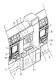
計数器7及びその周辺について図2に示す。計数器7は、玉返却口11から玉を受け入れてその数をカウントし、表示装置13に計数結果を表示する。発行ボタン15が押されると、プリンタ17から、計数結果がプリントされた前記のレシートが出力される。
【0038】
玉貸し機3は、その右側のパチンコ機1に向かって供給アーム19が延設されており、玉貸し機3に対して所要の金額が投入されると、対応する個数のパチンコ玉が供給アーム19を介して、パチンコ機1に供給される。
玉返却口11の左側にあるのは磁気記録装置20であり、ここに玉貯留箱を乗せると、玉貯留箱の裏側に記録された磁気信号を読み取ったり、逆に記録したりすることができる。なお、本図に略長方形にて示したのは、箱状部材に形成された窓の部分であり、実際には磁気記録装置20は、この窓の下方に配置されている。また、磁気記録装置20と同様の構成はカウンタの上にも設けられており、各パチンコ機1の下方に置かれた玉貯留箱の磁気信号を磁気記録装置21にて入出力可能にされている。
【0039】
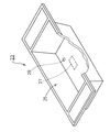
ここで玉貯留箱とは、各パチンコ機1から遊技者に対して払い出された玉を、パチンコ機1の下方にて受けて一旦、貯留し、計数器7まで運ぶのに用いられるものである。この玉貯留箱について図3を用いて説明する。
図3は、玉貯留箱23を示す斜視図であり、手前側の面を一部破断させてある。玉貯留箱23は、半透明の合成樹脂にて形成されており、貯留部25に玉を約3000個、貯留できるようにされている。貯留部25のほぼ中央裏側に磁気カード27が貼付されている(本図では破線にて示している)。この磁気カード27には、当該玉貯留箱23が用いられるパチンコ機1の台番号を初めとする様々な情報が記録可能にされている。つまり磁気カード27は、本発明の記憶手段に相当する。玉貯留箱23を磁気記録装置20や磁気記録装置21(図2参照)の上に乗せると、磁気カード27に記録されたこの台番号を読み取ったり、逆に台番号等を記録されたりする。磁気カード27の傍らには、遊技球が通過できない程度の径の丸穴29が形成されている。
【0040】
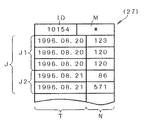
磁気カード27に記録されている磁気信号の一例を図4に示す。図4は、磁気カード27に記録された磁気信号を模式的に表したものである。実際には、本図のようにテーブル状に記録されているのではなく、符号化されて1次元的に記録されている。
【0041】
本図に示すように、磁気カード27の内容は、大きく分けて4つの情報からなる。第1に、その磁気カード27に固有(すなわち、玉貯留箱23にとっても固有)の番号ID、第2に、その玉貯留箱23が台移動に用いられたことを示すマークM、第3に、玉貯留箱23が使用されたパチンコ機1の台番号N、第4に、その台番号が当該磁気カード27に記録された日付Tである。この内、番号IDは、一旦記録されたら、磁気カード27が廃棄されるまで書き換えられることはないが、その他の情報は後述する処理により適宜更新されていく。本図に示した磁気カード27の内容は、固有の番号が「10154」、マークは台移動が為されたことを示す「*」、延べ5回分、使用されたことを示す台番号及びその日付が記録されている。なお、マークMは、台移動に使用されていない場合には、何も記録されていない状態にされているものとする。
【0042】
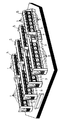
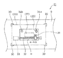
次に、磁気カード27に対して、磁気信号の入出力を行なう磁気記録装置21について、図5を用いて説明する。
すなわち図5は、カウンタ9に設けられた磁気記録装置21の概略を示す平面図である。なお、計数器7の備える磁気記録装置20も同様に構成されている。
【0043】
磁気記録装置21の外見は、カウンタ9の上に形成された窓Hと、そのまわりに壁状に設けられた略L字型の位置決め部30とからなっている。位置決め部30は、玉貯留箱23の底面の形状に対応して設けられており、ここに玉貯留箱23の底面の角を当接させると、磁気カード27が窓Hの略中央に位置するようにされている。このときの磁気カード27は、2点鎖線にて示した箇所に位置される。
【0044】
磁気カード27に対して磁気信号の入出力を行なう磁気ヘッド31は、窓Hの奥に設けられている。ボールネジ32がモータ33によって回転されると、磁気ヘッド31は、矢印A方向に往復駆動され、磁気カード27に対して磁気信号を帯状に記録する。窓H内にはこの他にも光センサ34a、34bが設けられている。この内、光センサ34aは、玉貯留箱23の丸穴29と整合する箇所に配置されている。空の玉貯留箱23を、(23)で示した2点鎖線の位置に置くと、光センサ34bは、玉貯留箱23の底の部分にて光を検知できなくなるが、光センサ34aは、丸穴29を通して光を検知できる。一方、玉貯留箱23に遊技球が入っていると、丸穴29が塞がれるため、光センサ34aも光を検知できなくなる。すなわち、光センサ34bによって玉貯留箱23が乗せられたことを検知でき、光センサ34aによってその玉貯留箱23に遊技球が入っているか否かを検知できる。つまり、光センサ34aが、本発明の空判定手段に相当する。
【0045】
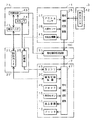
以上、図1〜図5を用いて説明したパチンコホールのシステムは、図6のようになっている。すなわち図6は、当該システムの概要を示すブロック図である。但し、パチンコ機1、玉貸し機3、及び磁気記録装置21については夫々1台にて代表させている。本図に示すようにパチンコホールのシステムは、既に示したパチンコ機1、玉貸し機3、計数器7、玉貯留箱23、磁気記録装置21に加え、ホール全体の出玉状況等を管理するホールコンピュータHCを主要部として構成されている。
【0046】
パチンコ機1は、遊技を初めとする様々な処理を行なう制御回路35と、アウト玉センサ37と、入賞センサ39と、玉払出機構41等からなっている。ここでアウト玉とは、遊技者がパチンコ機1に対して打ち込んだパチンコ玉のことであるが、アウト玉センサ37では特に、入賞口に入ることなく、遊技域の下部から排出されてしまった玉のみを検出する。入賞口に入った玉を数えるのが入賞センサ39である。制御回路35は、入賞センサ39によって、パチンコ機1の備える種々の入賞口に玉が入ったことが検知されると、各入賞口に設定されている数の賞球を玉払出機構41を用いて遊技者に対して払い出す。
【0047】
制御回路35は、前記の遊技以外の処理として、遊技者がパチンコ機1に対して発射した玉や、遊技者に対して払い出された玉を集計し、ホールコンピュータHCに対して出力する処理を行なう。発射された玉は、アウト玉センサ37による検知結果と、入賞センサ39による検知結果との合計にて求められる。この算出を行なうのが本発明の投入数算出手段としての処理に相当する。一方、遊技者が得た玉の数は、入賞センサ39による検知結果に、各入賞口に対して予め設定されている賞球数を掛けたものとなる。例えば、入賞センサ39による検知結果が、賞球7個の通常入賞口に10個、賞球5個の始動入賞口に6個、賞球15個の大入賞口に160個、入ったとすると、7×10+5×6+15×160=2500個が遊技者が得た玉の数となる。
【0048】
また、制御回路35には、玉貸し機3の貸玉センサ42も接続されており、遊技者が金を払って借りた玉の数も検知可能にされている。こうして借りた玉の数と前記の賞球数を加えたものが、遊技者が得た玉の総数となる。この総数を求めるのが本発明の貸与数算出手段としての処理に相当する。
【0049】
玉払出機構41から排出され、パチンコ機1から溢れ出たパチンコ玉は、前述のように玉貯留箱23の貯留部25に蓄えられる(本図において破線にて示した矢印は、このときの玉の流れを表している)。そして玉貯留箱23ごと、計数器7に運ばれて玉返却口11(図2参照)に投入される(図6に1点鎖線にて示した矢印は、このときの玉の流れを表している)。
【0050】
磁気記録装置21は、カウンタ9に玉貯留箱23が置かれたことを、光センサ34b(本図では光センサ34a、34bを単に34と記している)が検知すると、磁気記録装置21が備える制御回路43が磁気ヘッド31を駆動・制御して、磁気カード27に対して磁気信号の入出力を行なう。この処理の詳細に関しては後述する。
【0051】
計数器7は、玉返却口11、表示装置13、発行ボタン15、プリンタ17、磁気記録装置20に加え、玉の通過を検知する玉センサ45と、制御回路47と、クロック49と、を備えている。玉センサ45は、玉返却口11の奥に配置されており、玉が玉返却口11に投入されるとこれを検知し、制御回路47が検知回数をカウントし、表示装置13に計数結果を出力する。磁気記録装置20に玉貯留箱23が置かれた状態で、発行ボタン15が押されると、プリンタ17に計数結果を印字させる。
【0052】
ホールコンピュータHCは、本ホール全体の出玉、営業成績等を管理するものであり、このために必要なデータをパチンコ機1、計数器7、磁気記録装置21等から受信する。ホールコンピュータHCの制御回路51は、大容量の記憶装置を備えており、パチンコ機1から受信した玉数等に関する情報、計数器7から送られて来た計数結果等に関する情報、磁気記録装置21から送信された台移動等に関する情報等の多数の情報や、これらの情報から算出されたデータを記憶可能にされている。このデータとしては、各パチンコ機1の稼働状況、パチンコ機1における持ち玉数等が挙げられる。持ち玉数は、パチンコ機1の左側にある玉貸し機3から貸し出された玉数と、そのパチンコ機1の制御回路35にて算出された賞球数との合計から、同じく制御回路35にて算出された前述の発射玉数と、そのパチンコ機1の台番号Nが格納された磁気カード27を備えた玉貯留箱23により計数器7に投入された玉の数の合計を引くことにより分かる。これが本発明の保持数推定手段としての処理に相当する。
【0053】
また、計数器7の備える制御回路47においても、玉の計数、磁気カード27の読み取り、ホールコンピュータHCへのデータ送信、等の処理が行なわれる。以下、これらの制御回路43、47にて行なわれる処理について説明する。まず、磁気記録装置21の制御回路43が行なう磁気カード記録処理について図7を用いて説明する。
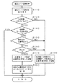
【0054】
すなわち図7は、磁気カード記録処理を表すフローチャートである。本処理は磁気記録装置21に玉貯留箱23が置かれたことが、光センサ34bにより検出されると起動される。まず、ステップ(以下、単にSと記す)110にて、磁気カード27の内容を読み取る。つまり、図5にて説明したモータ33を駆動させて、磁気ヘッド31をA方向に移動させ、図4に示したような磁気信号を読み取る。続くS120では、光センサ34aの検出結果に基づき、玉貯留箱23に玉が貯留されているか否かを判定する。玉がない場合はS130に進み、読み取った磁気信号から台移動を示すマークM(以下、台移動マークMと言う)を消去し、当該磁気記録装置21が設けられているパチンコ機1の台番号Nを付加したものを新たな磁気信号とし、磁気カード27に記録して本処理を終了する。なお、図4に示したように、台番号Nは、その日の日付Tと共に記録される。この、S120からS130への処理の流れは、空の玉貯留箱23が移動されても、後述するペナルティの対象にしないことを意味している。なお、S130において台移動マークMが初めからついていない場合には、台番号Nと日付Tのみを付加して記録する。
【0055】
一方、玉が貯留されている場合はS140に進み、磁気信号の中に台移動マークMがあるか否かを判定する。台移動マークMがある場合は、そのまま本処理を終了し、ない場合は、S150に進む。
S150では、磁気信号の中に他の台の台番号があるか否かを判定する。なければ、台移動が行なわれていないと見なしてS130に移行する。他の台の台番号が記録されていれば、S160に進み、その台番号Nに付けられた日付Tが、現在処理を行なっている日付と同じかどうかを判定する。同じ日付でない、つまり他の台番号Nが記録されたのが前日以前であれば、台移動ではないので、S130に進み、台番号Nと日付Tを付加したものを記録して本処理を終了する。
【0056】
他の台番号Nと共に記録された日付Tが同日である場合は、台移動が行なわれたことを意味するので、S170に進み、台移動マークMと、台番号Nと日付Tを付加したものを記録する。そしてS180にてホールコンピュータHCに、前台の台番号Nと、玉貯留箱23の番号IDとを送信し、本処理を終了する。ここで前台の台番号Nは、S170にて新たに記録された台番号Nの直前に記録されていた台番号Nであり、移動元のパチンコ機1を意味する。なお、こうして前台の台番号N、及び玉貯留箱23の番号IDを受け取ったホールコンピュータHCは、その時点で制御回路51が算出している台番号Nのパチンコ機1における持ち玉数を、記憶装置に格納する。
【0057】
本処理に沿って、図4に示した磁気信号が読み取られ記録されていく様子を示すと次のようになる。但し、図4に示した磁気信号の内、領域J2に示した日付T及び台番号Nについては記録されていない状態から、説明を始める。また、当日の日付は1996年8月21日とする。
【0058】
まず、番号IDとして「10154」が記録された空の玉貯留箱23が、台番号が「86」のパチンコ機1の下方に設けられた磁気記録装置21に置かれると、磁気カード記録処理が起動され、番号IDと、台移動マークMと、領域Jが読み取られる。領域J2は記録されていない状態なので、読み込まれた領域Jの内容は領域J1のみとなる。この玉貯留箱23には、玉は貯留されていないので、S120からS130に進み、台移動マークMを消去し、台番号「86」と、本日の日付「1996.08.21」を付加して終了する。
【0059】
この玉貯留箱23に、玉を貯留させた遊技者が、台番号「571」のパチンコ機1へ移動し、そのパチンコ機1の下方にある磁気記録装置21に玉貯留箱23を置いたとする。すると、そのパチンコ機1の下方に設けられた磁気記録装置21において、磁気カード記録処理が起動され、番号IDと、台移動マークMと、領域Jが読み取られる。この玉貯留箱23には、台番号「86」のパチンコ機1(以下、前台と言う)から払い出された玉が貯留されているので、S120からS140に進む。台移動マークMは、前台において行なわれた磁気カード記録処理のS130にて消去されているので、S150に進む。磁気信号の中には、そのS130にて記録された台番号「86」が記録されているので、S160に進む。そして、その台番号「86」の日付Tを見て、同日なので、S170に進み、台移動マークM「*」と、当該磁気記録装置21に対応するパチンコ機1の台番号「571」を記録する。そしてS180にて前台の台番号「86」と、番号ID「10154」をホールコンピュータHCに送信して終了する。
【0060】
更に、この遊技者が、玉貯留箱23に玉を貯留したまま台移動をすることを試みると、移動先の磁気記録装置21にて行なわれる磁気カード記録処理のS140にて、YESと判定されてその処理を終了する。つまり、既に台番号「86」の台から台番号「571」の台への台移動が行なわれているため、新たに台移動が行なわれたか否かを判定をする必要がない。
【0061】
なお、前記の説明の、台番号「86」で玉貯留箱23の使用を開始する際に、玉以外の何かによって丸穴29が塞がれていた場合は、S120でYESと判定されてしまう。しかし、S160の判定にて、領域J1の台番号の日付が前日となっているために、S130に進み、台移動と誤判定されることがない。
【0062】
また、領域J1において、台番号「120」が2行続けて記録されている部分があるが、これは、玉貯留箱23が一旦、足元等に置かれた後、再び同じ台にて使用されたことを意味している。1つの玉貯留箱23に納まり切らない程の玉を獲得した後、その納まらなかった分の玉を使い切ってしまった場合には、このような記録内容となることがある。
【0063】
つまり、磁気カード記録処理では、台移動の検知と、その発生を前台の台番号と共にホールコンピュータHCに送信する処理を行なう。換言すると、本処理では、台移動が行なわれた場合に、ペナルティを課すことや、表立った報知動作は一切、行なわない。また、S110が本発明の読取手段としての処理に相当し、S130及びS180が識別情報入力手段、S120〜S160が移動判定手段としての処理に相当する。
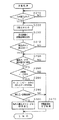
【0064】
次に、計数器7の制御回路47にて行なわれる計数処理について図8を用いて説明する。本処理は、玉返却口11に玉が投入されると起動されるものとする。すなわち、S210にて玉が投入されたと判定されると、S220にてその数をカウントし、S230にてその結果を表示装置13に出力する。240では発行ボタン15が押されたか否かを判定し、押されていなければ、更に玉が投入される可能性があるのでS220に移行する。
【0065】
押されていれば、S250に進み、計数器7の磁気記録装置20が玉貯留箱23の磁気信号の読み取りに成功したか否かを判定し、失敗していれば、するまで待機する。つまり、計数器7に玉を投入する際には、遊技者は、玉貯留箱23を磁気記録装置20においていることが要求される。さもなければ、計数結果が印字されたレシートが得られず、景品を獲得することができない。
【0066】
磁気信号の読み取りに成功すると、S260に進み、台移動マークMがあるか否かを判定する。もしなければ、S270に進んで、計数結果を印字されたレシートを発行して本処理を終了する。台移動マークMがあれば、S280に移行してホールコンピュータHCから、その玉貯留箱23によって台移動元のパチンコ機1において、払い出された持ち玉データを受信する。これは、S250にて読み取った磁気信号中の番号IDと、その番号IDを、ホールコンピュータHCが、自らの記憶装置内を検索し、その番号IDに関して、その日に格納された台番号Nと、持ち玉データとを送信することにより可能となる。この番号ID、及び台番号Nは、磁気カード記録処理のS180にてホールコンピュータHCに送信された番号ID、前台の台番号Nである。
続くS290では、受信した持ち玉数と、S230にて求められた計数結果とを比較し、計数結果の方が少なければ、S270に進み、計数結果の方が多ければ、S300に進み、持ち玉数とメッセージを印字出力して本処理を終了する。
【0067】
つまり、S290の判定にて、少ない方の数値が印字され、特に、持ち玉数の方が少なかった場合には、メッセージが付加される。ここでメッセージとは、計数結果が印字されなかったことを告げるもので、例えば「お客様は、番号86の台から他の台へと台移動をしたと認められますので、番号86の台にて獲得した玉の数を計数結果に替えさせて頂きます」といった内容のものである。
【0068】
つまり計数処理は、投入された玉を数えて、レシートに印字出力すると共に、台移動した遊技者に対してペナルティを課す処理となっている。
磁気カード記録処理、及び計数処理を行なうことにより、確実に台移動を検出することができる。また、玉貯留箱23が空だった場合(磁気カード記録処理のS120でNOと判定された場合)には、台移動と判定しないので、誤検出しない。また、磁気カード27に記録された磁気信号の内、当日に記録された台番号Nのみを対象として台移動か否かを判定するので、玉貯留箱23のメンテナンス性が良い。すなわち、判定の対象となるデータを当日分に限定しないと、閉店後に、全ての玉貯留箱23の、台移動マークMを消去する必要があるからである。これに対して、例えば、玉貯留箱23を、計数が終る都度、台移動マークM等をホールの従業員等に消去させてもよいが、作業ミス等により、台移動マークMが消去されなかった場合に、遊技者に不愉快な思い(すなわち、台移動していないのに、印字された獲得数が実際よりも少なくなってしまう等)をさせる虞があるので、従業員の負担が大きくなる。この点、判定の対象を当日分に限定することにより、従業員の負担が軽減される。また、こうすると、昨日や一昨日のデータをある程度、磁気カード27に残せるので、過去に遡って、その玉貯留箱23の使用状況を調べることができる。
【0069】
ところで、従来の、「台移動、即交換」というペナルティは、台移動を認めた場合に比べ、ホールにとって利益の減少(若しくは損害の増大)となる場合がある。これは、台移動して遊技を続けた結果、移動させた玉を減らすことがあるからである。この場合は、台移動の時点の持ち玉を計数させるよりも、最終的な持ち玉数を計数させて獲得数とした方が、ペナルティとして効果的である。但し、これは、実際に台移動を行なわせ、遊技を続行させて初めて、どちらの時点の玉数を獲得数とすべきだったかが分かるので、従来は不可能であった。この点、本発明のシステムによれば、台移動をした時点の持ち玉数と、計数処理における計数結果とを比較して、少ない方の玉数を獲得数とするので、確実にペナルティを課すことができる。
【0070】
以上、本発明を適用した実施例として、図1〜図6に示した構成を有し、図7及び図8に示した処理を行なう管理システムについて説明してきたが、本発明はこうした実施例に何等限定されるものではなく様々な態様で実施しうる。
例えば、計数処理のS240〜S250にて、発行ボタン15が押されても、磁気カード27の読み取りに成功しないとレシートを発行しないようにしたが、もっと前の段階で磁気カード27の読み取りを試みるようにしても良い。例を挙げると、磁気カード27の読み取りのチェックをS220の前で行ない、磁気信号が読み取れないとカウントを開始しないようにすることが考えられる。或は、玉返却口11にシャッターを設け、通常はこのシャッターを閉じておく。そして磁気カードの読み取りに成功すると、シャッターが開いて投入が可能になるようにしても良い。なお、理想的には、全ての玉貯留箱23が1つの台にて使用されたことをチェックすべきであるから、計数結果が玉貯留箱23の1箱分の容量を大きく上回ったときには、カウントの中止、或はシャッターを閉じる等して全ての玉貯留箱23の磁気信号をチェックするとよい。
【0071】
同じく計数処理にて、磁気記録装置20に乗せられた玉貯留箱23の磁気カード27から、磁気信号を読み取った後、磁気カード27を初期化(つまり磁気信号を消去)すると、日付Tを記録する必要がなくなる。
また、磁気カード27に代えてICカードにし、これに対応して磁気記録装置20、21もICカード記録装置に変更しても良い。こうすれば、ICカードに大量のデータを記録できるため、玉貯留箱23の利用状況のデータを長期間に亘って保存し、後日解析することも可能となる。また、磁気カード27やICカードに書き込まれた台番号等を電波にて発信する構成を各玉貯留箱23に設け、計数器7付近でこの電波を受信するようにしても良い。こうすれば、磁気記録装置20等に玉貯留箱を置く必要がなくなる。
【0072】
磁気カード記録処理のS130、及びS170において、磁気信号として日付Tを記録しているが、更に、時刻を記録しても良い。こうすると、その玉貯留箱23を用いた遊技がどの時刻から開始されたかが分かる。この場合に、磁気カード記録処理を定期的に(例えば3分ごと)起動させて、逐一、時刻を記録させれば、持ち玉遊技が行なわれた時間を推定できるようになる。
【0073】
また、図8の計数処理では、S290にて持ち玉と計数結果を比較して、少ない方を獲得数として印字したが、これを改良して、台移動を行なった際における持ち玉数が最も少ない値を獲得数としてもよい。こうすると、台移動が行なわれた回数が1回以下の場合は、S290と同じであるが、2回以上、行なわれた場合には、より厳しいペナルティとなることがある。例えば、玉を獲得した遊技者が1回目の台移動を行なって遊技を再開した処、持ち玉を減らし、更に2回目の台移動を行なって遊技した結果、玉数が最大となったとする。この場合、図8の処理では、獲得数は初めの台移動を行なったときの持ち玉数になる。前記の改良案では、持ち玉数が最小となった、2回目の台移動のときの持ち玉数が獲得数になる。
【0074】
これとは異なる変更を計数処理に施すと、遊技者間での玉の横流しを検知可能になる。例えば、同処理のS260を廃止し、S290を「持ち玉数が計数結果より所定個数(例えば500個)以上少ないか否か」に改め、S300を「計数結果から持ち玉数を引いた値とメッセージを印字出力する」に変える。
【0075】
もし横流しが発生すると、玉を受け取った側はその分だけ計数結果が増える。受け取った玉数は、計数結果から持ち玉数を引いた値になる。この数が500個よりも多い場合は、これを獲得数として印字する。つまり、受け取った玉を用いた遊技を通じて大量の玉を獲得しても、その分はカウントされず、もらった玉数のみが獲得数となる。従って、適切なペナルティを与えることができる。なお、この方法で、玉貯留箱23を用いた台移動も検知することができる。そしてこのときのメッセージは「お客様は、台移動または玉の横流しを受けたと思われますので、移動された玉数を計数結果に替えさせて頂きます」等とすると良い。
【図面の簡単な説明】
【図1】 本発明を適用したパチンコホールを示す斜視図である。
【図2】 実施例の遊技島5の計数器7の付近を示す斜視図である。
【図3】 実施例のパチンコホールにて用いられる玉貯留箱23の説明図である。
【図4】 磁気カード27に磁気信号が記録されている様子を示す説明図である。
【図5】 磁気記録装置21の構成の概略を示す説明図である。
【図6】 実施例のパチンコホールのシステム構成の概略を表すブロック図である。
【図7】 磁気記録装置21の制御回路43にて行なわれる磁気カード記録処理を示すフローチャートである。
【図8】 計数器7の制御回路47にて行なわれる計数処理を示すフローチャートである。
【符号の説明】
1…パチンコ機 5…遊技島 7…計数器
9…カウンタ 11…玉返却口 13…表示装置
15…発行ボタン 17…プリンタ 19…供給アーム
20、21…磁気記録装置 23…玉貯留箱
25…貯留部 27…磁気カード 29…丸穴
30…位置決め部 31…磁気ヘッド 32…ボールネジ
33…モータ 34a、34b…光センサ
35、43、47、51…制御回路 HC…ホールコンピュータ[0001]
BACKGROUND OF THE INVENTION
The present invention relates to a pachinko hall management system used in a pachinko hall in which a plurality of gaming machines such as pachinko machines and pachislot machines are installed, and in particular, movement of balls, medals and the like performed between gaming machines by a player. It relates to a system that can be detected.
[0002]
[Background Art and Problems to be Solved by the Invention]
In the pachinko hall, a player who has acquired a ball through a game in a pachinko machine may move to another pachinko machine with the ball. This action is called table movement and is prohibited in normal pachinko halls.
[0003]
However, there is no effective means for preventing the table movement. As countermeasures, there are methods such as watching with a surveillance camera or being careful by a store clerk, but none of them are effective. This is because the movement of the table is carried by carrying a box called a dollar box filled with balls, but this action is not done until the dollar box being carried is placed on another pachinko machine. I understand. Until then, for example, it would be indistinguishable from carrying a dollar box to the counter to exchange for prizes.
[0004]
As described above, in order to detect with the surveillance camera, it is necessary to keep an eye on the captured video. In addition, the store clerk has a variety of tasks and cannot afford to monitor a large number of players. For this reason, it may be said that the detection of the table movement is substantially impossible.
In addition, there is a hall that broadcasts in the hall saying “If a table movement is detected, it will be exchanged immediately (that is, let it enter the counter)”, but the effect is still weak because it is difficult to detect the table movement. .
[0005]
As a fraudulent act similar to this, balls may be moved between customers without using dollar boxes. For example, it is an act of crossing the acquired ball to the upper plate of the adjacent pachinko machine (portion for storing the ball to be fired) or the like. Although the amount that can be carried by one side flow is small, when it is repeated many times, several hundred balls may be moved.
[0006]
An action similar to that described above may be performed in a pachislot machine, and it is normally prohibited to move a medal to another pachislot machine.
This invention is made | formed in view of this subject, and it aims at making it possible to detect the stand movement in a pachinko hall.
[0007]
[Means for Solving the Problems]
The pachinko hall management system according to claim 1 of the present invention, which has been made to solve such a problem, includes a plurality of gaming machines that discharge value carriers such as balls and medals downward according to game results, and the respective games. In the pachinko hall management system used in the pachinko hall equipped with a counter installed below the machine,
A storage box that is placed on the counter and receives and stores the value carrier discharged downward from each gaming machine;
Storage means provided in the storage box and capable of storing identification information for distinguishing one of the gaming machines from other gaming machines;
Provided for each of the gaming machines, When the storage box is used to store the value carrier discharged from the gaming machine, The mounted on the counter Identification information input means for storing identification information corresponding to the gaming machine in the storage means of the storage box;
From the storage means of the storage box provided corresponding to each gaming machine and placed on the counter, Reading means for reading the identification information stored in the storage means;
Movement determining means for determining whether the storage box provided with the storage means has been moved from a different gaming machine based on the identification information in the storage means read by the reading means. Features.
[0008]
The present invention described in claim 2 is the pachinko hall management system according to claim 1,
An input number calculating means for detecting the number of value carriers input to the gaming machine for each gaming machine;
The number obtained by adding the value carrier rented to the player from the ball lending machine and the value carrier paid out to the player as a prize ball from the gaming machine Loan number calculating means for detecting for each gaming machine;
Counting means for receiving the value carrier from the outside and counting the number thereof;
In the gaming machine corresponding to the identification information read by the reading means, the number of the value carriers held by the player is at least the number of the value carriers counted by the counting means, the input number calculating means And holding number estimating means for estimating based on the number of value carriers detected by the number and the number of value carriers detected by the lending number calculating means.
[0009]
The present invention described in
The reading means is
It is provided corresponding to each gaming machine, and can read identification information from the storage means of the storage box placed on the counter,
The movement determination means is
It is provided corresponding to the reading means, and when the gaming machine indicated by the identification information read by the reading means and the gaming machine corresponding to the reading means do not match, it is determined that the game machine has been moved from a different gaming machine. It is characterized by being.
[0010]
The present invention according to claim 4 is the pachinko hall management system according to any one of claims 1 to 3,
Empty determination means for determining whether or not the storage box is empty,
The movement determination means is
When the storage box is determined to be empty by the empty determination means, the storage box is regarded as not being moved between a plurality of gaming machines regardless of the reading result by the reading means. Features.
[0011]
The present invention described in
The identification information input means
When storing the identification information, at least the date of the day is added and stored,
The movement determination means is
The determination that the storage box has been moved between a plurality of gaming machines is performed only when the dates of identification information for a plurality of machines read by the reading unit are the same.
[0012]
DETAILED DESCRIPTION OF THE INVENTION
The pachinko hall management system according to claim 1 (hereinafter also simply referred to as a management system) is intended for a pachinko hall in which a plurality of gaming machines are installed and a counter is provided therebelow. Here, the gaming machine discharges the value carrier downward according to the game result. If the gaming machine is a pachinko machine, a ball as a value carrier, and if it is a pachislot machine, a medal is discharged. Also, one counter need not be provided below each gaming machine. For example, following a normal pachinko hall, a plurality of gaming machines may be arranged in the horizontal direction, and a common counter may be bridged from one gaming machine to the other gaming machine.
[0013]
This counter is provided with a storage box for receiving and storing the value carrier discharged downward from each gaming machine. This is the same usage method as the dollar box described above, but the storage box of the present invention is provided with a storage means, and this storage means has identification information for identifying a gaming machine from other gaming machines, Can be stored. As the identification information, for example, a unique number assigned in advance to each gaming machine can be used.
[0014]
The identification information is stored in the storage means as the identification information input means, and the storage means of the storage box mounted and used on the counter stores the identification information corresponding to the gaming machine. The identification information input means may store the identification information in the storage means when operated by a store clerk or the like. When the storage box is placed on the counter, the identification information input means automatically starts and corresponds to the counter. The identification information of the gaming machine to be stored may be stored in the storage means.
[0015]
That is, when a storage box is used, identification information indicating a gaming machine that discharges the value carrier is recorded in the storage box. In other words, by reading the identification information stored in the storage means of the storage box, it is possible to know in which gaming machine the storage box was used. If the storage box is used sequentially in a plurality of gaming machines, a plurality of pieces of identification information are stored in the storage means.
[0016]
Reading means for reading the identification information is a reading means. Based on the result of the reading, the movement determining means determines whether or not the storage box has been moved between the plurality of gaming machines, that is, whether or not the table movement has been performed.
Therefore, according to the management system of the first aspect, it is possible to detect the movement of the table using the storage box. If any notification operation is performed based on this detection, it is possible to prevent the table from moving.
[0017]
Further, when this management system is applied, the number of value carriers held by the player can be estimated. Hereinafter, the value carrier is represented by a ball, and the gaming machine is described as a pachinko machine. In the case of a pachinko machine, the ball held by the player is called a holding ball, etc. This is a ball that the player borrows from a ball lending machine (usually next to each pachinko machine) and a prize ball It is a general term for balls that have been paid out. The management system according to claim 2 makes it possible to estimate this.
[0018]
That is, in the management system according to claim 2, an input number calculating means for detecting the number of value carriers input to the gaming machine, The number of value carriers rented to players from ball lending machines and value carriers paid out to players as prize balls from gaming machines In the gaming machine corresponding to the identification information read by the reading means, the number of value carriers held by the player is estimated in the lending number detecting means to be detected, the counting means for receiving the value carriers from the outside and counting the number thereof Holding number estimating means.
[0019]
If the gaming machine is a pachinko machine following the above example, the number-of-insertion calculating means corresponds to detecting the ball that has been fired, and it can be detected directly from the ball that has been fired, or the ball at the winning hole of the pachinko machine, etc. The number of inputs can be calculated by accumulating the detection results.
[0020]
The “lent” balls detected by the loan number calculating means mean balls lent out from the above-described ball lending machine and balls paid out as prize balls. The former ball can be detected from a ball lent from a ball lending machine or estimated from the amount of money thrown into the ball lending machine. In the case of a pachinko machine using a prepaid card, it can be calculated from the number of times a ball lending button provided in the pachinko machine is pressed. On the other hand, the latter ball is obtained by calculating from the passage of the ball at the winning port of the pachinko machine and the winning ball set in the winning port, or by directly detecting the number of balls paid out as the winning ball.
[0021]
As the counting means, usually, the counter provided in the pachinko hall can be used (if the gaming machine is a pachislot machine, a medal counter).
The number-of-holds estimating means determines the number of balls held by the player, at least the number of balls counted by the counting means, the number of balls detected by the throwing number calculating means, and the balls detected by the loan number calculating means. , Based on the number of
[0022]
A simple method for estimating the number of retentions is as follows. First, the identification information stored in the storage means of the storage box used for throwing the balls into the counting means is read by the reading means to identify which pachinko machine was used. Then, for the pachinko machine, the number of balls detected by the throwing number calculating means and the number of balls counted by the counting means are subtracted from the number of balls detected by the lending number calculating means. Thus, the number of balls held by the player is obtained.
[0023]
Therefore, according to the management system of the second aspect, the number of balls (medals for pachislot machines) held by the player can be estimated. Further, since the number of held pieces can be estimated in this way, it can also be estimated whether or not balls (or medals) are exchanged between players. That is, if a ball or the like is handed to a player of another gaming machine, the counting result by the counting means should be less than the ball (or medal) estimated by the holding number estimating means. On the other hand, in the game machine of the received player, the counting result is more. Accordingly, it is possible to detect not only the movement of the table but also the exchange of balls between players.
[0024]
Although it has been described that the movement determination means determines whether or not the table movement has been performed based on the identification information, specifically, for example, a plurality of pieces of gaming machine identification information are stored. It is good to judge by As another method, a management system according to
[0025]
That is, in the present invention described in
[0026]
The movement determination means determines the movement of the table using the reading means provided corresponding to the gaming machine. That is, when the gaming machine corresponding to the identification information read by the reading unit and the gaming machine corresponding to the reading unit do not match, it is determined that the table movement has been performed.
[0027]
If the table movement occurs, the reading means corresponding to the destination gaming machine can detect the table movement by reading the identification information corresponding to the source gaming machine.
Therefore, according to the management system of the third aspect, this can be detected immediately after the table is moved.
[0028]
In this way, in the management system of the present invention, the movement of the platform is detected by tracing the history stored in the storage means, so that the initial state of the storage box (when using the storage box for the first time on that day, It is necessary not to evaluate the history until then after the value carrier is discharged for counting and becomes empty. For this purpose, the used storage box is stacked, for example, near a counter (a machine for counting the number of value carriers acquired by the player), and the store clerk appropriately stores the stored storage box. The identification information stored in the storage means is deleted. In this way, even if the storage box is used, it is not determined that the table is moved. However, in the following cases, erroneous determination is made.
[0029]
That is, as a result of the player who has acquired a full value carrier in the storage box using up the value carrier in the subsequent game, the empty storage box may be left on the counter or the like. If a person playing a game in the vicinity of the counter acquires a value carrier, using the storage box that is left to store the value carrier will result in a false determination as a table move. The present invention according to claim 4 prevents this.
[0030]
That is, the management system according to claim 4 includes an empty determination means for determining whether or not a value carrier is contained in the storage box, and if it is determined that the value is empty, it is stored in the storage means. Regardless of the identification information, the movement determination means does not consider that the table movement has been performed.
[0031]
According to the management system of the fourth aspect, even when the storage box that has been left empty is used in another gaming machine, it is not erroneously determined as a table movement.
In order to determine whether the storage box is empty, the weight of the storage box placed on the counter is measured, or the storage box is made of a translucent material and A method such as detecting the presence or absence of a value carrier with a brightness sensor or the like can be considered. In these methods, even if a small number of value carriers are in the storage box, there is a possibility that the value carrier is erroneously determined to be empty. However, there is no problem if the number of value carriers moved is small enough to be ignored.
[0032]
In addition, as a case where the identification information for a plurality of vehicles is stored in the storage means in spite of the fact that the table is not moved, there may be a case where the previous day's identification information remains. In order to prevent this, after the pachinko hall is closed, the identification information of the storage means of all used storage boxes may be deleted (hereinafter referred to as initialization). However, since the number of storage boxes is enormous, it is a very time-consuming operation. In addition, there may be a mistake that the identification information was actually left, although it was originally initialized. As in the management system according to claim 4, if the storage box is empty, it can be prevented to some extent if it is not regarded as a table movement, but once the value carrier is accumulated, there is a possibility that it will be determined as a table movement. Will recur.
[0033]
The management system according to
[0034]
In this way, the previous day and the previous identification information are ignored, so there is no need to perform initialization after closing.
Therefore, according to the management system of the fifth aspect, since the trouble of initializing the storage box is greatly reduced, the storage box can be easily managed.
[0035]
As described above, in addition to the identification information, information such as a date may be stored in the storage unit. In addition to information that is updated such as identification information and date, such information may be recorded information that is not updated, such as a unique number for identifying the storage box from other storage boxes. Good.
[0036]
【Example】
Hereinafter, a pachinko hall to which the present invention is applied will be described with reference to FIG. In this pachinko hall, as shown in FIG. 1, a plurality of pachinko machines 1, 1,... And
[0037]
The counter 7 and its surroundings are shown in FIG. The counter 7 receives balls from the ball return port 11, counts the number thereof, and displays the count result on the
[0038]
The
On the left side of the ball return port 11 is a
[0039]
Here, the ball storage box is used to receive the balls paid out to the player from each pachinko machine 1 under the pachinko machine 1, temporarily store them, and carry them to the counter 7. is there. This ball storage box will be described with reference to FIG.
FIG. 3 is a perspective view showing the
[0040]
An example of the magnetic signal recorded on the
[0041]
As shown in the figure, the content of the
[0042]
Next, the
That is, FIG. 5 is a plan view schematically showing the
[0043]
The appearance of the
[0044]
A
[0045]
The pachinko hall system described above with reference to FIGS. 1 to 5 is as shown in FIG. That is, FIG. 6 is a block diagram showing an outline of the system. However, the pachinko machine 1, the
[0046]
The pachinko machine 1 includes a control circuit 35 that performs various processes including games, an
[0047]
As a process other than the above-described game, the control circuit 35 totalizes the balls fired by the player to the pachinko machine 1 and the balls dispensed to the player, and outputs them to the hall computer HC. To do. The fired ball is obtained by the sum of the detection result by the
[0048]
The control circuit 35 is also connected to a
[0049]
The pachinko balls discharged from the
[0050]
When the
[0051]
The counter 7 includes a ball return port 11, a
[0052]
The hall computer HC manages the appearance of the entire hall, sales results, and the like, and receives data necessary for this from the pachinko machine 1, the counter 7, the
[0053]
The
[0054]
That is, FIG. 7 is a flowchart showing the magnetic card recording process. This process is activated when the
[0055]
On the other hand, if the ball is stored, the process proceeds to S140, and it is determined whether or not there is a table movement mark M in the magnetic signal. If there is a table movement mark M, the process is terminated as it is, and if not, the process proceeds to S150.
In S150, it is determined whether or not there is a machine number of another machine in the magnetic signal. If not, it is assumed that the table is not moved and the process proceeds to S130. If the machine number of another machine is recorded, the process proceeds to S160, and it is determined whether or not the date T attached to the machine number N is the same as the current processing date. If it is not the same date, that is, if another machine number N was recorded before the previous day, it is not a machine movement, so the process proceeds to S130, and the process with the machine number N and date T added is recorded and the process is terminated. To do.
[0056]
If the date T recorded with the other machine number N is the same day, it means that the machine has been moved, so that the process proceeds to S170, and the machine movement mark M, the machine number N and the date T are added. Record. In step S180, the base number N of the front base and the number ID of the
[0057]
Along with this processing, the magnetic signal shown in FIG. 4 is read and recorded as follows. However, the description starts from a state in which the date T and the machine number N shown in the area J2 in the magnetic signal shown in FIG. 4 are not recorded. The date of the day is August 21, 1996.
[0058]
First, when the empty
[0059]
It is assumed that the player who has stored the balls in the
[0060]
Furthermore, if this player attempts to move the table while the ball is stored in the
[0061]
When starting the use of the
[0062]
In addition, in the area J1, there is a portion where the base number “120” is recorded continuously in two lines. This is used again on the same base after the
[0063]
That is, in the magnetic card recording process, the movement of the table is detected and the generation is transmitted to the hall computer HC together with the table number of the previous table. In other words, in this process, when a table is moved, no penalty is imposed and no obvious notification operation is performed. Further, S110 corresponds to processing as the reading means of the present invention, S130 and S180 correspond to processing as identification information input means, and S120 to S160 correspond to processing as movement determination means.
[0064]
Next, the counting process performed by the
[0065]
If it is pressed, the process proceeds to S250, where it is determined whether or not the
[0066]
If the reading of the magnetic signal is successful, the process proceeds to S260 where it is determined whether or not there is a table movement mark M. If not, the process proceeds to S270, a receipt printed with the counting result is issued, and the process is terminated. If there is a table movement mark M, the process proceeds to S280, and the handball data that has been paid out is received from the hall computer HC by the
In subsequent S290, the received number of possessed balls is compared with the counting result obtained in S230. If the counting result is smaller, the process proceeds to S270, and if the counting result is larger, the process proceeds to S300, The number and message are printed out and the process is terminated.
[0067]
That is, in the determination of S290, the smaller numerical value is printed, and in particular, when the number of possessed balls is smaller, a message is added. The message here indicates that the counting result has not been printed. For example, “The customer is deemed to have moved from the
[0068]
In other words, the counting process is a process of counting the thrown balls and printing them on a receipt and penalizing a player who has moved.
By performing the magnetic card recording process and the counting process, it is possible to reliably detect the table movement. Further, when the
[0069]
By the way, the conventional penalty of “moving the table, immediately changing” may result in a decrease in profit (or an increase in damage) for the hall as compared with the case where the movement of the table is permitted. This is because the balls moved may be reduced as a result of moving the table and continuing the game. In this case, it is more effective as a penalty to count the final number of balls to obtain the number of balls than to count the number of balls held at the time of table movement. However, this is not possible in the past because it is possible to know which ball number should have been acquired only after actually moving the table and continuing the game. In this respect, according to the system of the present invention, the number of balls possessed at the time of moving the table and the counting result in the counting process are compared, and the smaller number of balls is used as the number acquired, so a penalty is surely imposed. be able to.
[0070]
As described above, the management system that has the configuration shown in FIGS. 1 to 6 and performs the processing shown in FIGS. 7 and 8 has been described as an embodiment to which the present invention is applied. It is not limited at all and can be implemented in various modes.
For example, in S240 to S250 of the counting process, even if the
[0071]
Similarly, in the counting process, after reading the magnetic signal from the
Further, an IC card may be used in place of the
[0072]
In S130 and S170 of the magnetic card recording process, the date T is recorded as a magnetic signal, but the time may be further recorded. If it carries out like this, it will be understood from which time the game using the
[0073]
In the counting process of FIG. 8, the counting result is compared with the possessed ball in S290, and the smaller one is printed as the acquired number, but this is improved, and the number of possessed balls when moving the table is the highest. A small value may be obtained. In this way, if the number of times the table is moved is less than one, it is the same as S290, but if it is performed more than once, there may be a more severe penalty. For example, it is assumed that the player who has acquired the ball has restarted the game by performing the first movement of the table, the number of balls is maximized as a result of reducing the number of possessions and further performing the second movement of the table. In this case, in the process of FIG. 8, the acquired number is the number of possessed balls when the first table movement is performed. In the above improvement plan, the number of possessed balls at the time of the second platform movement, which has the minimum number of possessed balls, is the acquired number.
[0074]
If a change different from this is applied to the counting process, it becomes possible to detect the lateral flow of balls between players. For example, S260 of the same processing is abolished, S290 is changed to “whether the number of possessed balls is less than a predetermined number (for example, 500) or more than the counting result”, and S300 is changed to “a value obtained by subtracting the number of possessing balls from the counting result. Change to “Print message”.
[0075]
If cross-flow occurs, the side receiving the ball will increase the counting result accordingly. The number of balls received is a value obtained by subtracting the number of balls from the counting result. If this number is greater than 500, this is printed as the acquired number. In other words, even if a large number of balls are acquired through a game using the received balls, that amount is not counted, and only the number of balls received is the number acquired. Therefore, an appropriate penalty can be given. Note that this method can also detect table movement using the
[Brief description of the drawings]
FIG. 1 is a perspective view showing a pachinko hall to which the present invention is applied.
FIG. 2 is a perspective view showing the vicinity of the counter 7 of the
FIG. 3 is an explanatory diagram of a
FIG. 4 is an explanatory diagram showing a state in which a magnetic signal is recorded on the
FIG. 5 is an explanatory diagram showing an outline of the configuration of the
FIG. 6 is a block diagram illustrating an outline of a system configuration of a pachinko hall according to an embodiment.
7 is a flowchart showing a magnetic card recording process performed by a control circuit 43 of the
FIG. 8 is a flowchart showing a counting process performed by a
[Explanation of symbols]
1 ...
9 ... counter 11 ...
15 ...
20, 21 ...
25 ...
30 ... Positioning
33 ...
35, 43, 47, 51 ... Control circuit HC ... Hall computer
Claims (5)
前記カウンタに載置されて、前記各遊技機から下方に排出された前記価値担体を受け入れて貯留する貯留箱と、
該貯留箱に設けられ、前記遊技機の内の1台を、他の遊技機と識別する識別情報を格納可能な記憶手段と、
前記各遊技機に対応して設けられ、前記遊技機から排出される前記価値担体を貯留するために、前記貯留箱が用いられる際に、前記カウンタに載置された前記貯留箱の前記記憶手段に、該遊技機に対応する識別情報を格納する識別情報入力手段と、
前記各遊技機に対応して設けられ、前記カウンタに載置された前記貯留箱の前記記憶手段から、前記記憶手段に格納されている識別情報を読み取る読取手段と、
前記読取手段によって読み取られた前記記憶手段内の識別情報に基づき、その記憶手段が備えられた前記貯留箱が異なる遊技機から移動されたか否かを判定する移動判定手段と、
を備えたことを特徴とするパチンコホール管理システム。In a pachinko hall management system used in a pachinko hall comprising a plurality of gaming machines for discharging value carriers such as balls and medals downward according to game results, and a counter installed under each gaming machine ,
A storage box that is placed on the counter and receives and stores the value carrier discharged downward from each gaming machine;
Storage means provided in the storage box and capable of storing identification information for distinguishing one of the gaming machines from other gaming machines;
The storage means of the storage box placed on the counter when the storage box is used to store the value carrier that is provided corresponding to each gaming machine and is discharged from the gaming machine An identification information input means for storing identification information corresponding to the gaming machine;
Reading means for reading the identification information stored in the storage means from the storage means of the storage box provided corresponding to each gaming machine and placed on the counter ;
Based on the identification information in the storage means read by the reading means, a movement determination means for determining whether the storage box provided with the storage means has been moved from a different gaming machine,
Pachinko hall management system characterized by comprising
前記遊技機に対して投入された前記価値担体の数を該遊技機ごとに検知する投入数算出手段と、
玉貸し機から遊技者に貸し出された前記価値担体と、前記遊技機から賞球として遊技者に払い出された前記価値担体を加えた数を該遊技機ごとに検知する貸与数算出手段と、
外部から前記価値担体を受け入れてその数を計数する計数手段と、
前記読取手段によって読み取られた前記識別情報に対応する前記遊技機において、遊技者が保持する前記価値担体の数を、少なくとも、前記計数手段により計数された前記価値担体の数、前記投入数算出手段により検知された前記価値担体の数、及び貸与数算出手段により検知された前記価値担体の数、に基づいて推定する保持数推定手段と、
を備えたことを特徴とするパチンコホール管理システム。In the pachinko hall management system according to claim 1,
An input number calculating means for detecting the number of value carriers input to the gaming machine for each gaming machine;
Loan number calculating means for detecting, for each gaming machine, the value carrier lent to the player from the ball lending machine and the number of the value carrier paid out to the player as a prize ball from the gaming machine .
Counting means for receiving the value carrier from the outside and counting the number thereof;
In the gaming machine corresponding to the identification information read by the reading means, the number of the value carriers held by the player is at least the number of the value carriers counted by the counting means, the input number calculating means Holding number estimating means for estimating based on the number of value carriers detected by the number of value carriers detected by the loan number calculating means,
Pachinko hall management system characterized by comprising
前記読取手段が、
前記各遊技機に対応して設けられ、前記カウンタに載置された前記貯留箱の前記記憶手段から、識別情報を読み取り可能なもの、であり、
前記移動判定手段が、
前記読取手段に対応して設けられ、該読取手段によって読み取られた識別情報が示す遊技機と、該読取手段に対応する遊技機が一致しない場合に、異なる遊技機から移動されたと判定するもの
であることを特徴とするパチンコホール管理システム。In the pachinko hall management system according to claim 1 or 2,
The reading means is
It is provided corresponding to each gaming machine, and can read identification information from the storage means of the storage box placed on the counter,
The movement determination means is
It is provided corresponding to the reading means, and when the gaming machine indicated by the identification information read by the reading means and the gaming machine corresponding to the reading means do not match, it is determined that the game machine has been moved from a different gaming machine. Pachinko hall management system characterized by being.
前記貯留箱が空か否かを判定する空判定手段、を備え、
前記移動判定手段が、
前記空判定手段によって前記貯留箱が空と判定された場合には、前記読取手段による読み取り結果に係らず、複数の遊技機間を前記貯留箱が移動されていないと見なすもの、
であることを特徴とするパチンコホール管理システム。In the pachinko hall management system according to any one of claims 1 to 3,
Empty determination means for determining whether or not the storage box is empty,
The movement determination means is
When the empty determination unit determines that the storage box is empty, regardless of the reading result by the reading unit, the storage box is regarded as not being moved between a plurality of gaming machines,
Pachinko hall management system characterized by being.
前記識別情報入力手段が、
識別情報を格納する際に、少なくとも、当日の日付を付加して格納するものであり、
前記移動判定手段が、
複数の遊技機間を前記貯留箱が移動されたと見なす、前記判定を、前記読取手段によって読み取られた複数台数分の識別情報の日付が同じ場合のみに行なうもの
であることを特徴とするパチンコホール管理システム。In the pachinko hall management system according to any one of claims 1 to 4,
The identification information input means
When storing the identification information, at least the date of the day is added and stored,
The movement determination means is
The pachinko hall is characterized in that the storage box is considered to have been moved between a plurality of gaming machines, and the determination is performed only when the dates of identification information for a plurality of machines read by the reading means are the same. Management system.
Priority Applications (1)
| Application Number | Priority Date | Filing Date | Title |
|---|---|---|---|
| JP23317096A JP4061663B2 (en) | 1996-09-03 | 1996-09-03 | Pachinko hall management system |
Applications Claiming Priority (1)
| Application Number | Priority Date | Filing Date | Title |
|---|---|---|---|
| JP23317096A JP4061663B2 (en) | 1996-09-03 | 1996-09-03 | Pachinko hall management system |
Publications (2)
| Publication Number | Publication Date |
|---|---|
| JPH1076059A JPH1076059A (en) | 1998-03-24 |
| JP4061663B2 true JP4061663B2 (en) | 2008-03-19 |
Family
ID=16950833
Family Applications (1)
| Application Number | Title | Priority Date | Filing Date |
|---|---|---|---|
| JP23317096A Expired - Fee Related JP4061663B2 (en) | 1996-09-03 | 1996-09-03 | Pachinko hall management system |
Country Status (1)
| Country | Link |
|---|---|
| JP (1) | JP4061663B2 (en) |
Families Citing this family (5)
| Publication number | Priority date | Publication date | Assignee | Title |
|---|---|---|---|---|
| JP3805739B2 (en) * | 2002-10-28 | 2006-08-09 | 株式会社ソフィア | Game equipment |
| JP4508764B2 (en) * | 2004-08-02 | 2010-07-21 | ダイコク電機株式会社 | Amusement park management system |
| JP2006346168A (en) * | 2005-06-16 | 2006-12-28 | Takeya Co Ltd | Game parlor administration system, game medium storage box and game machine island |
| JP4736559B2 (en) * | 2005-06-16 | 2011-07-27 | 株式会社竹屋 | Notification system for gaming machine islands, gaming machine islands and gaming media storage boxes |
| JP5029820B2 (en) * | 2007-05-30 | 2012-09-19 | 株式会社北電子 | Game media storage box management system |
-
1996
- 1996-09-03 JP JP23317096A patent/JP4061663B2/en not_active Expired - Fee Related
Also Published As
| Publication number | Publication date |
|---|---|
| JPH1076059A (en) | 1998-03-24 |
Similar Documents
| Publication | Publication Date | Title |
|---|---|---|
| JP2869830B2 (en) | Gaming equipment | |
| JP4118366B2 (en) | Fraud detection device and playground system | |
| JP4189945B2 (en) | Game system | |
| JPH11300021A (en) | Game medium storage/re-using system | |
| JP4705767B2 (en) | Game system | |
| JP4061663B2 (en) | Pachinko hall management system | |
| JPH1024161A (en) | Closed type pachinko apparatus | |
| JP4222719B2 (en) | Amusement hall equipment | |
| JP2003275428A (en) | Game media counting system | |
| JP2894557B2 (en) | Ball game machine | |
| JP4645996B2 (en) | Game equipment | |
| JP5139131B2 (en) | Amusement system | |
| JP5726945B2 (en) | Amusement hall equipment | |
| JP4088981B2 (en) | Pachinko hall management system | |
| JP2800704B2 (en) | Pachinko parlor management equipment | |
| AU648116B2 (en) | Recording medium reader, ball lending machine and medal lending machine | |
| JP2824835B2 (en) | Gaming machine | |
| JPS6244508B2 (en) | ||
| JP3536024B2 (en) | Game medal circulation system | |
| JPH11192370A (en) | Pachinko hall fraud detection device | |
| JPH11276711A (en) | Game medium management and settlement system | |
| JPH10118301A (en) | Card ejector/recording in game machine | |
| JP6049793B2 (en) | Amusement hall equipment | |
| JPS5822786Y2 (en) | pachinko machine | |
| JPH09294859A (en) | Management device for game house |
Legal Events
| Date | Code | Title | Description |
|---|---|---|---|
| A131 | Notification of reasons for refusal |
Free format text: JAPANESE INTERMEDIATE CODE: A131 Effective date: 20070828 |
|
| A977 | Report on retrieval |
Free format text: JAPANESE INTERMEDIATE CODE: A971007 Effective date: 20070830 |
|
| A521 | Written amendment |
Free format text: JAPANESE INTERMEDIATE CODE: A523 Effective date: 20071029 |
|
| TRDD | Decision of grant or rejection written | ||
| A01 | Written decision to grant a patent or to grant a registration (utility model) |
Free format text: JAPANESE INTERMEDIATE CODE: A01 Effective date: 20071204 |
|
| A61 | First payment of annual fees (during grant procedure) |
Free format text: JAPANESE INTERMEDIATE CODE: A61 Effective date: 20071217 |
|
| R150 | Certificate of patent or registration of utility model |
Free format text: JAPANESE INTERMEDIATE CODE: R150 |
|
| FPAY | Renewal fee payment (event date is renewal date of database) |
Free format text: PAYMENT UNTIL: 20110111 Year of fee payment: 3 |
|
| LAPS | Cancellation because of no payment of annual fees |