JP4041972B2 - Thermoelectric system with improved efficiency using thermal separation - Google Patents
Thermoelectric system with improved efficiency using thermal separation Download PDFInfo
- Publication number
- JP4041972B2 JP4041972B2 JP2002564308A JP2002564308A JP4041972B2 JP 4041972 B2 JP4041972 B2 JP 4041972B2 JP 2002564308 A JP2002564308 A JP 2002564308A JP 2002564308 A JP2002564308 A JP 2002564308A JP 4041972 B2 JP4041972 B2 JP 4041972B2
- Authority
- JP
- Japan
- Prior art keywords
- thermoelectric
- elements
- array
- heat
- fluid
- Prior art date
- Legal status (The legal status is an assumption and is not a legal conclusion. Google has not performed a legal analysis and makes no representation as to the accuracy of the status listed.)
- Expired - Fee Related
Links
- 238000000926 separation method Methods 0.000 title claims description 23
- 238000002955 isolation Methods 0.000 claims abstract description 15
- 238000004519 manufacturing process Methods 0.000 claims abstract description 14
- 238000001816 cooling Methods 0.000 claims description 35
- 238000010438 heat treatment Methods 0.000 claims description 28
- 230000001953 sensory effect Effects 0.000 claims description 4
- 230000004044 response Effects 0.000 claims description 3
- 238000011156 evaluation Methods 0.000 claims description 2
- 238000003491 array Methods 0.000 abstract 1
- 239000000758 substrate Substances 0.000 description 99
- 239000012530 fluid Substances 0.000 description 84
- 239000000463 material Substances 0.000 description 39
- 230000008859 change Effects 0.000 description 15
- 238000010586 diagram Methods 0.000 description 15
- 238000012546 transfer Methods 0.000 description 15
- 238000000034 method Methods 0.000 description 14
- 239000007787 solid Substances 0.000 description 11
- 239000007788 liquid Substances 0.000 description 10
- RYGMFSIKBFXOCR-UHFFFAOYSA-N Copper Chemical compound [Cu] RYGMFSIKBFXOCR-UHFFFAOYSA-N 0.000 description 7
- 229910052802 copper Inorganic materials 0.000 description 7
- 239000010949 copper Substances 0.000 description 7
- 230000006872 improvement Effects 0.000 description 7
- 239000011343 solid material Substances 0.000 description 6
- 230000008901 benefit Effects 0.000 description 5
- 230000007423 decrease Effects 0.000 description 5
- 238000013461 design Methods 0.000 description 5
- 238000010292 electrical insulation Methods 0.000 description 5
- 229910052751 metal Inorganic materials 0.000 description 4
- 239000002184 metal Substances 0.000 description 4
- XEEYBQQBJWHFJM-UHFFFAOYSA-N Iron Chemical compound [Fe] XEEYBQQBJWHFJM-UHFFFAOYSA-N 0.000 description 3
- QSHDDOUJBYECFT-UHFFFAOYSA-N mercury Chemical compound [Hg] QSHDDOUJBYECFT-UHFFFAOYSA-N 0.000 description 3
- 229910052753 mercury Inorganic materials 0.000 description 3
- 238000005057 refrigeration Methods 0.000 description 3
- 238000013459 approach Methods 0.000 description 2
- 229910052797 bismuth Inorganic materials 0.000 description 2
- JCXGWMGPZLAOME-UHFFFAOYSA-N bismuth atom Chemical compound [Bi] JCXGWMGPZLAOME-UHFFFAOYSA-N 0.000 description 2
- 239000012612 commercial material Substances 0.000 description 2
- 239000004020 conductor Substances 0.000 description 2
- 239000000284 extract Substances 0.000 description 2
- 239000004519 grease Substances 0.000 description 2
- 238000009413 insulation Methods 0.000 description 2
- 239000012212 insulator Substances 0.000 description 2
- 239000000203 mixture Substances 0.000 description 2
- 230000035699 permeability Effects 0.000 description 2
- 230000008569 process Effects 0.000 description 2
- 239000004065 semiconductor Substances 0.000 description 2
- XSOKHXFFCGXDJZ-UHFFFAOYSA-N telluride(2-) Chemical compound [Te-2] XSOKHXFFCGXDJZ-UHFFFAOYSA-N 0.000 description 2
- 239000004593 Epoxy Substances 0.000 description 1
- 241000920340 Pion Species 0.000 description 1
- 229910052782 aluminium Inorganic materials 0.000 description 1
- XAGFODPZIPBFFR-UHFFFAOYSA-N aluminium Chemical compound [Al] XAGFODPZIPBFFR-UHFFFAOYSA-N 0.000 description 1
- PNEYBMLMFCGWSK-UHFFFAOYSA-N aluminium oxide Inorganic materials [O-2].[O-2].[O-2].[Al+3].[Al+3] PNEYBMLMFCGWSK-UHFFFAOYSA-N 0.000 description 1
- 230000000712 assembly Effects 0.000 description 1
- 238000000429 assembly Methods 0.000 description 1
- 238000004364 calculation method Methods 0.000 description 1
- 239000002131 composite material Substances 0.000 description 1
- 230000001419 dependent effect Effects 0.000 description 1
- 230000009977 dual effect Effects 0.000 description 1
- 230000000694 effects Effects 0.000 description 1
- 230000005611 electricity Effects 0.000 description 1
- 239000000835 fiber Substances 0.000 description 1
- 239000007789 gas Substances 0.000 description 1
- 239000011810 insulating material Substances 0.000 description 1
- 229910052742 iron Inorganic materials 0.000 description 1
- 230000007246 mechanism Effects 0.000 description 1
- 238000012544 monitoring process Methods 0.000 description 1
- ORQBXQOJMQIAOY-UHFFFAOYSA-N nobelium Chemical compound [No] ORQBXQOJMQIAOY-UHFFFAOYSA-N 0.000 description 1
- 238000005457 optimization Methods 0.000 description 1
- 238000005086 pumping Methods 0.000 description 1
- 238000011160 research Methods 0.000 description 1
- 229910052701 rubidium Inorganic materials 0.000 description 1
- IGLNJRXAVVLDKE-UHFFFAOYSA-N rubidium atom Chemical compound [Rb] IGLNJRXAVVLDKE-UHFFFAOYSA-N 0.000 description 1
- 239000013535 sea water Substances 0.000 description 1
- 230000011664 signaling Effects 0.000 description 1
- 239000002002 slurry Substances 0.000 description 1
- 238000005476 soldering Methods 0.000 description 1
- 229910052714 tellurium Inorganic materials 0.000 description 1
- PORWMNRCUJJQNO-UHFFFAOYSA-N tellurium atom Chemical compound [Te] PORWMNRCUJJQNO-UHFFFAOYSA-N 0.000 description 1
- 238000010998 test method Methods 0.000 description 1
- 229910052716 thallium Inorganic materials 0.000 description 1
- BKVIYDNLLOSFOA-UHFFFAOYSA-N thallium Chemical compound [Tl] BKVIYDNLLOSFOA-UHFFFAOYSA-N 0.000 description 1
- 239000002470 thermal conductor Substances 0.000 description 1
Images


Classifications
-
- F—MECHANICAL ENGINEERING; LIGHTING; HEATING; WEAPONS; BLASTING
- F02—COMBUSTION ENGINES; HOT-GAS OR COMBUSTION-PRODUCT ENGINE PLANTS
- F02G—HOT GAS OR COMBUSTION-PRODUCT POSITIVE-DISPLACEMENT ENGINE PLANTS; USE OF WASTE HEAT OF COMBUSTION ENGINES; NOT OTHERWISE PROVIDED FOR
- F02G1/00—Hot gas positive-displacement engine plants
- F02G1/04—Hot gas positive-displacement engine plants of closed-cycle type
- F02G1/043—Hot gas positive-displacement engine plants of closed-cycle type the engine being operated by expansion and contraction of a mass of working gas which is heated and cooled in one of a plurality of constantly communicating expansible chambers, e.g. Stirling cycle type engines
-
- F—MECHANICAL ENGINEERING; LIGHTING; HEATING; WEAPONS; BLASTING
- F25—REFRIGERATION OR COOLING; COMBINED HEATING AND REFRIGERATION SYSTEMS; HEAT PUMP SYSTEMS; MANUFACTURE OR STORAGE OF ICE; LIQUEFACTION SOLIDIFICATION OF GASES
- F25B—REFRIGERATION MACHINES, PLANTS OR SYSTEMS; COMBINED HEATING AND REFRIGERATION SYSTEMS; HEAT PUMP SYSTEMS
- F25B21/00—Machines, plants or systems, using electric or magnetic effects
- F25B21/02—Machines, plants or systems, using electric or magnetic effects using Peltier effect; using Nernst-Ettinghausen effect
- F25B21/04—Machines, plants or systems, using electric or magnetic effects using Peltier effect; using Nernst-Ettinghausen effect reversible
-
- F—MECHANICAL ENGINEERING; LIGHTING; HEATING; WEAPONS; BLASTING
- F28—HEAT EXCHANGE IN GENERAL
- F28D—HEAT-EXCHANGE APPARATUS, NOT PROVIDED FOR IN ANOTHER SUBCLASS, IN WHICH THE HEAT-EXCHANGE MEDIA DO NOT COME INTO DIRECT CONTACT
- F28D15/00—Heat-exchange apparatus with the intermediate heat-transfer medium in closed tubes passing into or through the conduit walls ; Heat-exchange apparatus employing intermediate heat-transfer medium or bodies
- F28D15/02—Heat-exchange apparatus with the intermediate heat-transfer medium in closed tubes passing into or through the conduit walls ; Heat-exchange apparatus employing intermediate heat-transfer medium or bodies in which the medium condenses and evaporates, e.g. heat pipes
- F28D15/0275—Arrangements for coupling heat-pipes together or with other structures, e.g. with base blocks; Heat pipe cores
-
- H—ELECTRICITY
- H10—SEMICONDUCTOR DEVICES; ELECTRIC SOLID-STATE DEVICES NOT OTHERWISE PROVIDED FOR
- H10N—ELECTRIC SOLID-STATE DEVICES NOT OTHERWISE PROVIDED FOR
- H10N10/00—Thermoelectric devices comprising a junction of dissimilar materials, i.e. devices exhibiting Seebeck or Peltier effects
-
- H—ELECTRICITY
- H10—SEMICONDUCTOR DEVICES; ELECTRIC SOLID-STATE DEVICES NOT OTHERWISE PROVIDED FOR
- H10N—ELECTRIC SOLID-STATE DEVICES NOT OTHERWISE PROVIDED FOR
- H10N10/00—Thermoelectric devices comprising a junction of dissimilar materials, i.e. devices exhibiting Seebeck or Peltier effects
- H10N10/10—Thermoelectric devices comprising a junction of dissimilar materials, i.e. devices exhibiting Seebeck or Peltier effects operating with only the Peltier or Seebeck effects
- H10N10/13—Thermoelectric devices comprising a junction of dissimilar materials, i.e. devices exhibiting Seebeck or Peltier effects operating with only the Peltier or Seebeck effects characterised by the heat-exchanging means at the junction
-
- H—ELECTRICITY
- H10—SEMICONDUCTOR DEVICES; ELECTRIC SOLID-STATE DEVICES NOT OTHERWISE PROVIDED FOR
- H10N—ELECTRIC SOLID-STATE DEVICES NOT OTHERWISE PROVIDED FOR
- H10N10/00—Thermoelectric devices comprising a junction of dissimilar materials, i.e. devices exhibiting Seebeck or Peltier effects
- H10N10/10—Thermoelectric devices comprising a junction of dissimilar materials, i.e. devices exhibiting Seebeck or Peltier effects operating with only the Peltier or Seebeck effects
- H10N10/17—Thermoelectric devices comprising a junction of dissimilar materials, i.e. devices exhibiting Seebeck or Peltier effects operating with only the Peltier or Seebeck effects characterised by the structure or configuration of the cell or thermocouple forming the device
-
- F—MECHANICAL ENGINEERING; LIGHTING; HEATING; WEAPONS; BLASTING
- F25—REFRIGERATION OR COOLING; COMBINED HEATING AND REFRIGERATION SYSTEMS; HEAT PUMP SYSTEMS; MANUFACTURE OR STORAGE OF ICE; LIQUEFACTION SOLIDIFICATION OF GASES
- F25B—REFRIGERATION MACHINES, PLANTS OR SYSTEMS; COMBINED HEATING AND REFRIGERATION SYSTEMS; HEAT PUMP SYSTEMS
- F25B2321/00—Details of machines, plants or systems, using electric or magnetic effects
- F25B2321/02—Details of machines, plants or systems, using electric or magnetic effects using Peltier effects; using Nernst-Ettinghausen effects
- F25B2321/021—Control thereof
-
- F—MECHANICAL ENGINEERING; LIGHTING; HEATING; WEAPONS; BLASTING
- F25—REFRIGERATION OR COOLING; COMBINED HEATING AND REFRIGERATION SYSTEMS; HEAT PUMP SYSTEMS; MANUFACTURE OR STORAGE OF ICE; LIQUEFACTION SOLIDIFICATION OF GASES
- F25B—REFRIGERATION MACHINES, PLANTS OR SYSTEMS; COMBINED HEATING AND REFRIGERATION SYSTEMS; HEAT PUMP SYSTEMS
- F25B2500/00—Problems to be solved
- F25B2500/01—Geometry problems, e.g. for reducing size
-
- F—MECHANICAL ENGINEERING; LIGHTING; HEATING; WEAPONS; BLASTING
- F25—REFRIGERATION OR COOLING; COMBINED HEATING AND REFRIGERATION SYSTEMS; HEAT PUMP SYSTEMS; MANUFACTURE OR STORAGE OF ICE; LIQUEFACTION SOLIDIFICATION OF GASES
- F25B—REFRIGERATION MACHINES, PLANTS OR SYSTEMS; COMBINED HEATING AND REFRIGERATION SYSTEMS; HEAT PUMP SYSTEMS
- F25B33/00—Boilers; Analysers; Rectifiers
-
- H—ELECTRICITY
- H01—ELECTRIC ELEMENTS
- H01L—SEMICONDUCTOR DEVICES NOT COVERED BY CLASS H10
- H01L2924/00—Indexing scheme for arrangements or methods for connecting or disconnecting semiconductor or solid-state bodies as covered by H01L24/00
- H01L2924/0001—Technical content checked by a classifier
- H01L2924/0002—Not covered by any one of groups H01L24/00, H01L24/00 and H01L2224/00
Landscapes
- Engineering & Computer Science (AREA)
- Mechanical Engineering (AREA)
- General Engineering & Computer Science (AREA)
- Physics & Mathematics (AREA)
- Thermal Sciences (AREA)
- Combustion & Propulsion (AREA)
- Sustainable Development (AREA)
- Chemical & Material Sciences (AREA)
- Life Sciences & Earth Sciences (AREA)
- Cooling Or The Like Of Semiconductors Or Solid State Devices (AREA)
- Measuring Temperature Or Quantity Of Heat (AREA)
- Compositions Of Macromolecular Compounds (AREA)
- Control Of Temperature (AREA)
- Devices For Blowing Cold Air, Devices For Blowing Warm Air, And Means For Preventing Water Condensation In Air Conditioning Units (AREA)
- Air-Conditioning For Vehicles (AREA)
- Cooling Or The Like Of Electrical Apparatus (AREA)
- Electromechanical Clocks (AREA)
- Organic Insulating Materials (AREA)
- Inorganic Insulating Materials (AREA)
Abstract
Description
本発明は、より効率の高いヒートコンディションおよび/またはコールドコンディションを構成するための改良型熱電システムに関する。 The present invention relates to an improved thermoelectric system for constructing more efficient heat and / or cold conditions.
熱電デバイス(TE)には、電気が流れると材料の両端間に熱勾配が発生するという特殊な材料の特性が利用されている。従来の熱電デバイスには、その内部に、熱電材料としてP型およびN型半導体が利用されている。これらの熱電デバイスは、目標とする加熱機能または冷却機能が得られるように、物理的かつ電気的に構成されている。 The thermoelectric device (TE) uses a special material property that a thermal gradient is generated between both ends of the material when electricity flows. In conventional thermoelectric devices, P-type and N-type semiconductors are used as thermoelectric materials. These thermoelectric devices are physically and electrically configured so as to obtain a target heating function or cooling function.
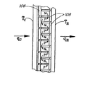
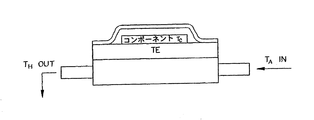
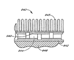
TEに関係する、冷却および加熱のためのいくつかの基本的な方程式、理論、研究、試験方法およびデータが開示されている(例えば、非特許文献1参照)。図1A、1Bは、現在、熱電デバイスに採用されている最も一般的な構成を示す図であり、(a)は斜視図、(b)は部分拡大正面図である。通常、P型およびN型熱電エレメント102は、2枚の基板104の間に挟まれており、長方形のアセンブリ100内に配列されている。P型およびN型の両方の熱電エレメントを通って、電流Iが流れる。熱電エレメント102は、熱電エレメント102の端部にはんだ付けされた銅シャント106を介して、直列に接続されている。DC電圧108が印加されると、TEエレメントの両端間に温度勾配が発生する。図2および図3は、いずれも図1に示したTEアセンブリ100を使用したシステムの概要を示す図で、図2は液体の流れを示す図、図3は冷却または加熱対象物を示す図である。
Several basic equations, theory, research, test methods and data for cooling and heating related to TE are disclosed (see, for example, Non-Patent Document 1). 1A and 1B are diagrams showing the most general configuration currently employed in thermoelectric devices, where (a) is a perspective view and (b) is a partially enlarged front view. Typically, P-type and N-type thermoelectric elements 102 are sandwiched between two
熱電エレメントを通って電流が流れると、熱電エレメントの一方の端部がクーラになり、もう一方の端部がウォーマになる。TEは、液体、気体およびその他の対象物の冷却に広く使用されている。 As current flows through the thermoelectric element, one end of the thermoelectric element becomes a cooler and the other end becomes a warmer. TE is widely used for cooling liquids, gases and other objects.
TEデバイスに関する最も一般的な形の基本方程式は、以下の通りである。
(1) qc=αITc−(1/2)I2R−KΔT
(2) qin=αIΔT+I2R
(3) qh=αIΔTh−(1/2)I2R−KΔT
上記の式で、qcは冷却率(コールド側からの熱含量除去率)であり、qinは、システムに入力される電力である。また、qhはシステムの熱出力である。ここで、
α=ゼーベック係数
I=電流
Tc=コールド側絶対温度
Th=ホット側絶対温度
R=電気抵抗
K=熱伝導係数
である。また、α、RおよびKは仮定定数であるか、または適当な温度範囲に対して適切に平均化された値である。
The most general form of basic equation for TE devices is:
(1) q c = αIT c − (1/2) I 2 R−KΔT
(2) q in = αIΔT + I 2 R
(3) q h = αIΔT h - (1/2) I 2 R-KΔT
In the above formula, q c is the cooling rate (heat content removal rate from the cold side), and q in is the power input to the system. Q h is the heat output of the system. here,
α = Seebeck coefficient I = current T c = cold side absolute temperature T h = hot side absolute temperature R = electric resistance K = heat conduction coefficient. Α, R and K are assumed constants or values appropriately averaged over an appropriate temperature range.
定常状態下においては、入力エネルギと出力エネルギは、以下のように平衡する。
(4) qc+qin=qh
また、冷凍および加熱業界で使用されている意味での性能を解析するためには、以下の定義が必要である。
(5) β=qc/qin =冷却性能係数(冷却COP)
(6) γ=qh/qin=加熱COP
(7) qc/qin+qin/qin=qh/qin
(8) β+1=γ
したがって、βおよびγは密接に関係しており、γは「1」の数だけ常にβより大きい。これらの式を操作することにより、βまたはγのいずれか、すなわちqcまたはqhのいずれかが最大になる条件を求めることができる。
Under steady state conditions, input energy and output energy are balanced as follows:
(4) q c + q in = q h
Moreover, in order to analyze the performance in the meaning used in the refrigeration and heating industry, the following definitions are necessary.
(5) β = q c / q in = cooling coefficient of performance (cooling COP)
(6) γ = q h / q in = heating COP
(7) q c / q in + q in / q in = q h / q in
(8) β + 1 = γ
Therefore, β and γ are closely related, and γ is always greater than β by the number “1”. By manipulating these equations, it is possible to obtain a condition in which either β or γ, that is, either q c or q h is maximized.
βの最大値をβmで表し、qcの最大値対するCOPをβcmで表すと、以下の式が得られる。 When the maximum value of β is represented by β m and the COP for the maximum value of q c is represented by β cm , the following equation is obtained.

(11) Z=α2/Z(RK)=(α2ρ)/λ=フィギュアオブメリット
(12) Tm=(Tc+Th)/2
ここで、 λ=材料の熱伝導率
ρ=材料の電気抵抗率
側面が平行の単純な固体形状の場合、K=λ×面積/長さであることに留意されたい。同様に、R=(ρ×長さ)/面積である。したがって、KおよびRは共に、あらゆる形状変化、例えば長さ、面積、コナリティ(conality)等の変化に影響される。また、KおよびRは、機械的または他の手段によるフレキシブルエレメントの形状変化にも影響される。
(11) Z = α 2 / Z (RK) = (α 2 ρ) / λ = Figure of Merit (12) T m = (T c + T h ) / 2
Where λ = the thermal conductivity of the material ρ = the electrical resistivity of the material Note that K = λ × area / length for a simple solid shape with parallel sides. Similarly, R = (ρ × length) / area. Thus, both K and R are affected by any shape change, such as changes in length, area, conality, etc. K and R are also affected by changes in the shape of the flexible element due to mechanical or other means.
βmおよびqcmは、Z、TcおよびThにのみ依存している。したがって、Zはフィギュアオブメリット(性能指数)と呼ばれ、TEシステムの性能を特徴付ける基本的なパラメータである。Zの大きさが、図1に示す幾何学および他のほとんどの幾何学における熱電性能を左右し、また、今日における熱電エレメントの用途を決定付けている。 beta m and q cm is dependent Z, the T c and T h only. Therefore, Z is called a figure of merit (performance index) and is a basic parameter characterizing the performance of the TE system. The size of Z affects the thermoelectric performance in the geometry shown in FIG. 1 and most other geometries, and also determines the application of thermoelectric elements today.
最新の材料を使用した熱電デバイスが、特定の航空宇宙産業およびいくつかの商用目的に使用されている。しかし、システムの効率が、フレオン類の流体(例えば、冷蔵庫、自動車HVACシステム、建築物HVACシステム、家庭用空気調和装置等に使用されている)を使用するほとんどの冷凍システムの効率と競争するには、あまりにも悪すぎるため、その用途は限られたものとなっている。 Thermoelectric devices using the latest materials are used for specific aerospace industries and some commercial purposes. However, the efficiency of the system will compete with that of most refrigeration systems that use freon-type fluids (eg, used in refrigerators, automotive HVAC systems, building HVAC systems, home air conditioners, etc.). Because it is too bad, its use is limited.
(9)式の最大熱電効率と、カルノーサイクル効率(任意の冷却システムの理論的最大システム効率)であるCmとを比較すると、限界が明らかになる。 Comparing the maximum thermoelectric efficiency of equation (9) with C m , which is the Carnot cycle efficiency (theoretical maximum system efficiency of any cooling system), the limit becomes clear.
ZTa≒1
いくつかの商用材料は、ある程度の狭い温度範囲に対してZTa=1であるが、現在の商用材料では、ZTaが「1」の数を超えることがない。図4は、ZTaが「1」の数を超えないことを示したものである。実験室的な材料の中には、ZTa=2〜4を示す材料もあるが、これらの材料は商業規模では生産されていない。一般的には、より良好な材料を商用的に利用することができるようになっているが、本発明の利点を不要にするほどの材料ではない。
ZT a ≒ 1
Some commercial materials have ZT a = 1 for some narrow temperature range, but with current commercial materials, ZT a does not exceed the number “1”. FIG. 4 shows that ZT a does not exceed the number “1”. Some laboratory materials exhibit ZT a = 2-4, but these materials are not produced on a commercial scale. In general, better materials can be used commercially, but not so much that they do not obviate the benefits of the present invention.
現在、いくつかの構成の熱電デバイスが、自動車座席の冷却システム、携帯型冷却器および冷蔵庫、科学アプリケーション向け高効率液体システム、エレクトロニクスおよび光ファイバシステムの冷却、および赤外線センシングシステムの冷却に使用されている。 Currently, several configurations of thermoelectric devices are used for automotive seat cooling systems, portable coolers and refrigerators, high efficiency liquid systems for scientific applications, electronics and fiber optic systems, and infrared sensing systems. Yes.
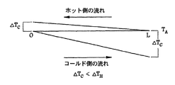
これらのすべてのデバイスに共通していることは、ThがTEのホット側全体にわたって一様であり、同様に、Tcがコールド側全体にわたって一様であることである。このようなデバイスはほとんどの場合、TEのホット側およびコールド側エンドプレートにアルミナ基板(良好な熱伝導体)が使用され、また、熱交換器として銅またはアルミニウムのフィンまたはブロックが、少なくとも一方の側に使用されている。 Common to all of these devices, T h is uniform across the hot side of the TE, similarly, is that T c is uniform across the cold side. Such devices most often use alumina substrates (good thermal conductors) for the TE hot and cold end plates, and copper or aluminum fins or blocks as heat exchangers. Used on the side.
したがって、良好な近似を得るための条件は、図5に示す線図で表すことができる。このケースでは、ΔTは、ΔT=ΔTc+ΔThであるΔTcおよびΔThで、それぞれコールド側およびホット側に分割されている。(1)式および(2)式を(5)式に代入すると、下記の(14)式が得られる。 Therefore, the conditions for obtaining a good approximation can be represented by the diagram shown in FIG. In this case, ΔT is divided into a cold side and a hot side, respectively, with ΔT c and ΔT h where ΔT = ΔT c + ΔT h . Substituting Equations (1) and (2) into Equation (5) yields the following Equation (14).
(15) qh=CpMΔTh
CpMは、ホット側を通過する流体の単位時間当たり(例えば、1秒当たり)の熱量である。
(15) q h = C p MΔT h
C p M is the amount of heat per unit time (for example, per second) of the fluid passing through the hot side.
したがって、CpMが与えられた要求値qhに対して極めて大きい場合、ΔThは極めて小さくなる。しかし、これには欠点があり、大型ファン、すなわちポンプを必要とし、また、流体が大量に廃棄される(つまり、より効果的な冷却を達成するべく、プロセスの一部として、冷却されることなく流体が廃棄される)。 Therefore, when C p M is extremely large for a given required value q h , ΔT h is extremely small. However, this has drawbacks, requires a large fan, i.e. a pump, and the fluid is discarded in large quantities (i.e. it is cooled as part of the process to achieve more effective cooling). Fluid is discarded).
第2のオプションは、熱が受動的に放熱されるよう、ホット側のヒートシンクを極めて大きくすることである。その例は、ホット側が車両シャーシと極めて良好に熱接触している、自動車における低電力TE、またはTEが外殻、延いては海水と良好に熱接触している、潜水艦におけるTEシステムである。しかしながら、これらの方法は一般的には実施が困難であり、またはコスト、重量、サイズまたはその他の条件が、それらの用途を制限している。そのために、ほとんどのデバイスで、ΔTがΔTcより実質的に大きくなっており、効率の問題を抱えている。
全体的には、熱電エレメントのアセンブリ全体を、熱的に分離されたサブアセンブリに細分化することにより、効率改善型熱電デバイスが得られている。熱的な分離を利用し、かつ、熱電エレメントにより冷却または加熱される材料の位置および流れ方向を制御することにより、全体の効率が改善されている。また、ΔTを変化させ、かつ、熱電デバイス全体における各部の熱電エレメントの物理的、熱的および電気的特性を変化させることによって、効率が改善されている。 Overall, improved efficiency thermoelectric devices have been obtained by subdividing the entire assembly of thermoelectric elements into thermally separated subassemblies. By utilizing thermal separation and controlling the position and flow direction of the material that is cooled or heated by the thermoelectric element, the overall efficiency is improved. Also, the efficiency is improved by changing ΔT and changing the physical, thermal and electrical properties of the thermoelectric elements in each part of the entire thermoelectric device.
本発明に係る一つの態様には、冷却または加熱される少なくとも1つの媒体を用いる熱電システム(熱電デバイス)が包含されている。このシステムは、冷却側および加熱側を備えた熱電エレメントアレイ(以下、熱電アレイと略記する)を形成している複数の熱電エレメントを有しており、これらの複数の熱電エレメントは、熱電アレイに沿った少なくとも1つの方向で、相互に実質的に熱的に分離されている。冷却側および/または加熱側のうちの少なくとも一方の側に、少なくとも1つの熱交換器が設けられており、少なくとも1つの熱電エレメントと熱的に接触している。熱交換器は、熱電エレメントの熱的な分離を有効に維持するように構成されている。 One aspect of the invention includes a thermoelectric system (thermoelectric device) that uses at least one medium to be cooled or heated. The system has a plurality of thermoelectric elements forming a thermoelectric element array (hereinafter abbreviated as a thermoelectric array) having a cooling side and a heating side, and the plurality of thermoelectric elements are connected to the thermoelectric array. Are substantially thermally separated from each other in at least one direction along. At least one heat exchanger is provided on at least one of the cooling side and / or the heating side and is in thermal contact with at least one thermoelectric element. The heat exchanger is configured to effectively maintain the thermal isolation of the thermoelectric elements.
一実施の形態では、流体、固体または流体と固体の組み合わせなどの媒体が、熱電アレイの少なくとも一方の側の少なくとも一部に沿って、少なくとも1つの方向に移動するようになっている。他の実施の形態では、例えば電気抵抗(以下、抵抗と略記する)などの少なくとも1つの熱電エレメントの特性が、媒体の移動方向で変化している。抵抗は、熱電エレメントの長さの変化、熱電エレメントの断面積の変化、各熱電エレメントの機械的構成の変化、または少なくとも1つの熱電材料の抵抗率など、多くの方法によって変化させることができ、また、アプリケーションに適した任意の方法で変化させることができる。 In one embodiment, a medium, such as a fluid, a solid, or a combination of fluid and solid, is adapted to move in at least one direction along at least a portion of at least one side of the thermoelectric array. In other embodiments, the characteristics of at least one thermoelectric element, such as electrical resistance (hereinafter abbreviated as resistance), vary in the direction of media movement. The resistance can be changed in many ways, such as changing the length of the thermoelectric element, changing the cross-sectional area of the thermoelectric element, changing the mechanical configuration of each thermoelectric element, or the resistivity of at least one thermoelectric material, Moreover, it can be changed by any method suitable for the application.
さらに別の実施の形態では、熱電アレイ内の少なくともいくつかの熱電エレメントを流れる電流が、他の熱電エレメントを流れる電流と異なっている。 In yet another embodiment, the current flowing through at least some thermoelectric elements in the thermoelectric array is different from the current flowing through other thermoelectric elements.
熱交換器は、ポスト、フィンまたはヒートパイプなどで、複数の部分で構成されており、各々の部分が少なくとも1つの熱電エレメントと熱的に接触し、少なくともいくつかの部分が、媒体が移動する方向で相互に実質的に熱的に分離されていることが好ましい。これらの部分の熱的な分離が熱電エレメントの熱的な分離に対応し、それにより、効果的に熱的に分離されたサブアセンブリが提供されることが好ましい。一実施の形態では、冷却側および加熱側の各々に熱交換器が設けられている。別の実施の形態としては、一方の側にヒートシンクを設け、もう一方の側に熱交換器を設けることもできる。ヒートシンクは、一方の端部で熱電アレイと熱接触し、もう一方の端部でヒートシンクと熱接触しているヒートパイプを介して、熱電アレイの一方の側に接合しているのがよい。また、別の実施の形態では、熱電エレメントに、少なくとも1つの磁界が印加されている。 The heat exchanger is composed of a plurality of parts, such as posts, fins or heat pipes, each part being in thermal contact with at least one thermoelectric element and at least some parts moving the medium Preferably they are substantially thermally separated from one another in the direction. Preferably, the thermal separation of these portions corresponds to the thermal separation of the thermoelectric elements, thereby providing an effectively thermally separated subassembly. In one embodiment, a heat exchanger is provided on each of the cooling side and the heating side. In another embodiment, a heat sink can be provided on one side and a heat exchanger can be provided on the other side. The heat sink may be joined to one side of the thermoelectric array via a heat pipe that is in thermal contact with the thermoelectric array at one end and in thermal contact with the heat sink at the other end. In another embodiment, at least one magnetic field is applied to the thermoelectric element.
熱電システムの機械的な構成を調整することにより、熱電システムの少なくとも1つの特性を動的に調整できるようにすることが好ましい。熱電システムに接続された制御システムにより、制御システムへの少なくとも1つの入力に基づいて、機械的な構成が調整される。制御システムは、調整によって効率を動的に改善することができるように動作することが好ましい。そのアルゴリズムが提供されており、制御システムはそのアルゴリズムに従って動作するように構成されている。一実施の形態では、制御システムは、制御システムへの少なくとも1つの入力に基づいて、少なくとも1つの特性を調整するようになっている。 It is preferable to be able to dynamically adjust at least one characteristic of the thermoelectric system by adjusting the mechanical configuration of the thermoelectric system. A control system connected to the thermoelectric system adjusts the mechanical configuration based on at least one input to the control system. The control system preferably operates such that efficiency can be dynamically improved by adjustment. An algorithm is provided and the control system is configured to operate according to the algorithm. In one embodiment, the control system is adapted to adjust at least one characteristic based on at least one input to the control system.
熱的な分離、特性の変化、電流の変化、磁界の印加および制御システムなどの様々な特徴を、個々のアプリケーションに、様々な組み合わせで、または単独で使用することができる。 Various features such as thermal isolation, property changes, current changes, magnetic field application and control systems can be used in individual applications, in various combinations, or alone.
本発明に係る別の態様には、流体、固体または流体と固体の組み合わせなど、冷却または加熱される少なくとも1つの媒体を用いる熱電システムの製造方法が包含されている。この方法には、冷却側および加熱側を備えた熱電アレイ内に、複数の熱電エレメントを形成するとともに、複数の前記熱電エレメントを、前記熱電アレイの少なくとも1つの方向で、相互に実質的に熱的に分離させるステップと、前記熱電エレメントの熱的な分離が有効に維持される状態で、前記熱電アレイの少なくとも一方の側で熱交換が行われるようにするステップとが含まれている。 Another aspect of the invention includes a method of manufacturing a thermoelectric system that uses at least one medium to be cooled or heated, such as a fluid, a solid, or a combination of a fluid and a solid. In this method, a plurality of thermoelectric elements are formed in a thermoelectric array having a cooling side and a heating side, and the plurality of thermoelectric elements are substantially heated relative to each other in at least one direction of the thermoelectric array. And thermally exchanging at least one side of the thermoelectric array in a state where thermal isolation of the thermoelectric elements is effectively maintained.
この熱電システムの製造方法に係る一実施の形態では、媒体は、熱電アレイの少なくとも一方の側の少なくとも一部に沿って、少なくとも1つの方向に移動するようになっている。この方法に係る別の実施の形態には、さらに、熱電エレメントの抵抗または機械的な構成など、少なくとも1つの特性を媒体が移動する方向で変化させるステップが含まれている。例えば、抵抗は、少なくともいくつかの熱電エレメントの長さ、断面積、機械的な構成または抵抗率の変化など、任意の多くの方法で変化させることができる。一実施の形態では、少なくとも1つの特性を変化させるステップには、少なくとも1つの特性を動的に調整するステップが含まれている。この調整は、感覚入力、すなわちユーザによって入力される少なくとも1つのパラメータの評価に基づいていることが好ましい。この調整は、アルゴリズムによって制御されるようになっている。 In one embodiment of the method of manufacturing a thermoelectric system, the medium moves in at least one direction along at least a portion of at least one side of the thermoelectric array. Another embodiment of the method further includes changing at least one characteristic, such as the resistance or mechanical configuration of the thermoelectric element, in the direction in which the medium moves. For example, the resistance can be changed in any of a number of ways, such as changing the length, cross-sectional area, mechanical configuration, or resistivity of at least some thermoelectric elements. In one embodiment, changing the at least one characteristic includes dynamically adjusting the at least one characteristic. This adjustment is preferably based on sensory input, ie an evaluation of at least one parameter input by the user. This adjustment is controlled by an algorithm.
一実施の形態では、熱交換するステップには、各々の部分が少なくとも1つの熱電エレメントと熱的に接触し、少なくともいくつかの部分が、媒体が移動する方向で、他の部分から実質的に熱的に分離された複数の部分からなる熱交換器を形成するステップが含まれている。それらの部分は、ポスト、フィンまたはヒートパイプ、またはその他の適切な熱交換器材料など、任意の数で構成することができる。一実施の形態では、熱交換するステップには、冷却側および加熱側の両方で熱交換するステップが含まれている。別法としては、上記方法には、熱電アレイの少なくとも一方の側から熱を放熱させるステップが含まれている。 In one embodiment, the heat exchanging step includes each portion in thermal contact with at least one thermoelectric element, and at least some of the portions are substantially different from other portions in the direction in which the media moves. A step of forming a heat exchanger comprising a plurality of thermally separated parts is included. The parts can be composed of any number, such as posts, fins or heat pipes, or other suitable heat exchanger materials. In one embodiment, the heat exchanging step includes exchanging heat on both the cooling side and the heating side. Alternatively, the method includes dissipating heat from at least one side of the thermoelectric array.
別の実施の形態に係る方法には、さらに、熱電アレイ内の少なくともいくつかの熱電エレメントを流れる電流を変化させるステップが含まれている。さらに別の実施の形態に係る方法には、さらに、熱電エレメントに、少なくとも1つの磁界を印加するステップが含まれている。 The method according to another embodiment further includes changing the current flowing through at least some of the thermoelectric elements in the thermoelectric array. The method according to yet another embodiment further includes applying at least one magnetic field to the thermoelectric element.
以下、本発明に係る上記の熱電システム、その製造方法およびその他の特徴を、多数の図を参照しながら詳細に説明する。本発明に係る好ましい実施の形態に関する詳細な説明は、添付する図に基づいてなされるものとする。 Hereinafter, the thermoelectric system according to the present invention, its manufacturing method, and other features will be described in detail with reference to a number of drawings. The detailed description of the preferred embodiments of the present invention will be made with reference to the accompanying drawings.
本発明について、説明用として、図面に示す実施例および特定の実施の形態を使用して紹介する。目的とする改善を達成するために、様々な構成がどのように使用されているかを示すために、様々な実施例が示されているが、これらの特定の実施の形態は説明用であり、本発明の技術的範囲を制限することを意図したものではない。 The present invention will be introduced by way of illustration using the examples and specific embodiments shown in the drawings. Although various examples are shown to illustrate how various configurations are used to achieve the desired improvements, these specific embodiments are illustrative, It is not intended to limit the technical scope of the present invention.
図6は、TEシステム600の全体の構成を一般化して示すブロック図である。電源602に、ホット側603およびコールド側604を備えた熱電アセンブリ(熱電エレメント)601が電気的に接続されている。熱電アセンブリ601は、ホット側603上のホット側熱交換器607と良好に熱接触し、かつ、コールド側604上のコールド側熱交換器608と良好に熱接触している。適切なダクトまたはパイプを備える(図示省略)ホット側603の流体源605およびコールド側604の流体源606が、それぞれの熱交換器607および608に流体を送っている。加熱された流体609および冷却された流体610は、図の右側へ向かってシステムから流出する。特定のアプリケーション(以下に示す実施例を備えている)では、熱交換器607または608の一方がヒートシンクに置き換えられ、それにより、ヒートシンクに置き換えられた側の流体源または流体の必要性が取り除かれている。
FIG. 6 is a block diagram showing a general configuration of the entire TE system 600. A thermoelectric assembly (thermoelectric element) 601 having a
一般的には、本明細書により、さらに詳細に説明するように、本発明は、熱電システムの構成の改良による熱電システムの効率改善に関するものであり、加熱または冷却される媒体が流れる方向において、熱電システムのエレメント間またはステージ間の熱的な分離を提供するものである。以下に示す実施例のほとんどは、冷却に焦点が絞られているが、本発明の原理は、加熱アプリケーションにも適用することができる。 In general, as described in more detail herein, the present invention relates to improving the efficiency of a thermoelectric system by improving the configuration of the thermoelectric system, in the direction in which the medium to be heated or cooled flows, It provides thermal isolation between elements or stages of a thermoelectric system. Although most of the examples shown below are focused on cooling, the principles of the present invention can also be applied to heating applications.
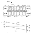
図7Aは、本発明によって実質的に効率が改善されるTEシステム700に係る第1の実施の形態を示す図である。図7Aに示したように、TEエレメントアレイ(熱電アレイ)701は、複数のTEエレメント704をサンドイッチしているホット側基板702およびコールド側基板703を使用して構成されている。複数のピン705が、ホット側基板702およびコールド側基板703の両方に、それらの基板を介してTEエレメント704と良好に熱接触し、TEシステム700の熱交換器を構成している。図7Aに示したように、ピン705は、釘に極めて類似した形状を有しており、そのヘッド706は、TEエレメント704と良好に熱接触している(ホット側およびコールド側)。ピン705は、熱伝導率の高い銅または他の材料であることが好ましい。アプリケーションに応じて、または熱伝達が生じる流体に応じて、ピン705を他の熱交換器の構成すなわち幾何学的構成に置き換えることができる。例えばヒートパイプまたはフィンなど、このような幾何学的構成のいくつかについて以下で説明する。熱交換器は、ピンからピンへ流体が流れる方向の熱伝達を最小にし、かつ、TEエレメント704からピン705に対しては良好な熱伝達を維持するものでなければならない。
FIG. 7A is a diagram illustrating a first embodiment of a
ホット側基板702およびコールド側基板703は、TEエレメントアレイ701の長さ方向に沿って、流体が流れる方向で熱伝導率が小さくなるような材料でできており、かつ/またはそのように幾何学的に構成されている。基板702および703は、熱伝導率が比較的小さいので、それよってTEエレメント704からピン705への熱伝達が重大な影響を受けないように、薄いことが好ましい。ホット側基板702およびコールド側基板703は、TEエレメントアレイ701をまとめて保持し、かつ、TEエレメント704間において要求される従来の電気的接続を提供する導電部分を有している。その材料は、銅が選択的にクラッドされているか、厚さ約0.050mmの銅が両面(回路用およびピン705への熱付着用)にクラッドされた導電性材料が選択的にクラッドされていることが好ましい。好ましい材料の1つは、Kapton MTまたはその他のフレキシブル電気的絶縁印刷回路材料である。Kapton MTの熱伝導率は約0.5W/m・Kであり、厚さは約0.025mmである。別法としては、熱伝導率を実質的にもっと大きく、例えば20W/m・Kとし、かつ、基板702および703が十分に薄い(一実施の形態では、約0.05mm未満)場合、または隣接するピンとピンの間の流れ方向における熱的な分離を提供するような形状である場合に、性能上の有効な効果を得ることができる。TEシステム700の構成が目指しているのは、それぞれの熱交換器部品と良好に熱接触した状態で、流体が流れる方向において、個々のTEエレメント704を、実質的に熱的に分離した状態に維持することである。
The
上記の熱交換器は、特定の熱交換器の1つである。本発明のシステムによって得ることができる効率利得(efficiency gain)を利用するためには、熱交換器が局所ポイントレベルで有効であることが重要である。つまり、熱交換器の各々のポイントで、加熱または冷却すべき媒体の温度が、その位置における熱交換器の温度に近い温度になっていることが重要である。熱電システムに沿って移動する冷却される媒体と、各々の位置における熱交換器との間の温度差が大きい場合に熱効率が低下する。したがって、本発明によれば、熱電エレメントは、流れの方向で実質的に熱的に分離され、熱交換器は、熱電エレメントと良好に熱接触していることが好ましい。このように、熱電エレメントは、実質的に流れの方向で熱的に分離されている。また、熱交換器は、移動媒体の性質を考慮して設計されているため、あらゆる与えられた位置において、熱交換器と、冷却または加熱される媒体との間の温度差が、入力から出力までの全温度差と比較して小さくなっている。 The above heat exchanger is one of specific heat exchangers. In order to take advantage of the efficiency gain that can be obtained with the system of the present invention, it is important that the heat exchanger be effective at the local point level. That is, at each point of the heat exchanger, it is important that the temperature of the medium to be heated or cooled is close to the temperature of the heat exchanger at that position. Thermal efficiency is reduced when the temperature difference between the cooled medium moving along the thermoelectric system and the heat exchanger at each location is large. Thus, according to the present invention, it is preferred that the thermoelectric elements are substantially thermally separated in the direction of flow and the heat exchanger is in good thermal contact with the thermoelectric elements. In this way, the thermoelectric elements are thermally separated substantially in the direction of flow. Also, because the heat exchanger is designed with the nature of the moving medium in mind, at any given location, the temperature difference between the heat exchanger and the medium being cooled or heated will be output from the input. It is smaller than the total temperature difference until.
また、熱電エレメント間に提供される熱的な分離のレベルは、トレードオフおよび個々のアプリケーションに応じて様々である。例えば、熱交換器に対しては、熱伝導が良好なことが望ましいが、熱電エレメントから熱電エレメントへの基板に沿った方向では、熱的な分離が要求される。効率は、エレメント間の熱的な分離が良好なほど改善されるが、この効率は、熱電エレメントと熱交換器との間の局部的な熱伝導不良に起因する効率損失、または、熱交換器と冷却または加熱される媒体との間の無効熱伝達によってオフセットされる。したがって、必ずしも最適ではないとしても、個々のアプリケーションに対する実用的な設計を行うためには、各アプリケーションには、相互に関係するこれら3つの特性のバランスを取る必要がある。 Also, the level of thermal isolation provided between thermoelectric elements varies depending on trade-offs and individual applications. For example, for heat exchangers, good thermal conductivity is desirable, but thermal isolation is required in the direction along the substrate from thermoelectric element to thermoelectric element. Efficiency is improved with better thermal isolation between the elements, but this efficiency is a loss of efficiency due to localized heat transfer failure between the thermoelectric element and the heat exchanger, or heat exchanger Offset by reactive heat transfer between the medium and the medium to be cooled or heated. Therefore, to make a practical design for an individual application, although not necessarily optimal, each application must balance these three characteristics that are interrelated.
図7Bおよび7Cは、図7Aに示したTEシステムにおける一つの可能な構造を、より詳細に示した図である。図7Bは、図7Aに示したTEシステム700の一部分を拡大して示した部分拡大断面図である。図7Cは、図7Bに示した基板を直角方向から見た図であり、コールド側基板の底部から見たTE側を示す平面図である。なお、図7Cは、TEエレメント704のアレイ(4エレメント幅)に関する回路トレースの一つの可能なレイアウトを示した図である。幅すなわち長さ方向のエレメントの数は、アプリケーションに適合するように選択され、任意の数にすることができる。図7Bには、コールド側基板703が示されている。ホット側基板702の構造も、図7Bに示した実施の形態と同様である。
7B and 7C show in more detail one possible structure in the TE system shown in FIG. 7A. FIG. 7B is a partially enlarged cross-sectional view showing a part of the
図7Aに示した基板703は、電気絶縁層714で構成されており、電気絶縁層714の上に、TEエレメント704を1つに接続するために使用される回路715が形成される。電気絶縁層714の一面側には、金属パッド716(図7B)が設けられており、金属パッド716はピン705と良好に熱接触している。この熱接触は、例えば、はんだ付けまたはエポキシボンディングによって達成されるが、他の方法の利用も可能である。ピンが電気絶縁層714に直接取り付けられ、良好に熱接触し、かつ、良好な熱エネルギの伝達特性を有している場合には、金属パッド716は不要である。ピンを電気絶縁層714の拡張部分とすることにより、ピンまたはピンの機能を果たす他の部分を単一ユニット構造にすることができる。
A
別法として、または組合せとして、電気絶縁層714を異方性とすることにより、電気絶縁層714の熱伝導率を、TEエレメントからピンの方向に向かってより大きくし、かつ、流れの方向に向かってより小さくすることができる。電気絶縁層714における平面に直角な方向の熱伝達を良好にすることができる別の方法は、電気絶縁層714を極めて薄くすることである。電気絶縁層714は、流れの方向に対しては良好な熱的絶縁体であることが好ましいが、電気絶縁層714中のギャップ717によって熱絶縁を提供し、または熱絶縁をさらに強化することができる。それにより、電気絶縁層714の熱伝導率をTEエレメント704間の空気または他の媒体の熱伝導率に置き換えることができる。一実施の形態では、熱絶縁性の高い材料がギャップ717に充填されている。
Alternatively, or in combination, by making the
図7Aに示したTEシステム700は、右から左へ向かって流体が流れるように構成されている。適切なダクト711を通って、周囲環境(ambient)温度TAで、流体710が流入し、熱交換器として機能しているピン705を通るように流れる。この流体は、冷却器の温度TCに冷却された流体712、およびより高い温度THに加熱された流体713として左側から流出する。この実施の形態では、ヘッド706を含むピン705は、相互に良好に熱接触していないため、各ピンは、流体が流れる方向では、相互の熱的な分離が効果的に行われている。TEエレメントアレイ701および特にホット側およびコールド側の基板702、703は、流体が流れる方向に対する熱伝導率が低い材料であり、かつ、TEエレメント704とピン705との間に良好な熱伝達を備えるように設計されることが好ましい。
The
TEエレメント704は従来のTEエレメントであるが、図7Aに示した設計のTEエレメントアレイ701のTEエレメント704に改良を施すことにより、効率をさらに改善することができる。一実施の形態では、TEエレメント704は、図7Aの右端部分に、より小さい抵抗を持たせ、図の左側へ向かって抵抗が大きくなるように構成されているか、逆の方向に、抵抗が大きくなる方向と流れの方向とが一致するように構成されている。より大きい抵抗端である最後のTEエレメントの抵抗は、従来のTEエレメントの抵抗に概ね等しい抵抗であることが好ましい。x方向(図7Aの右から左へ向かう方向)の抵抗Rは、
(16) R(x)(R0(x/L)
に近いことが有利である。上式で、TE全体の電流が一定である場合、
R0=従来のTE中のエレメントの電気抵抗
R(x)=xにおけるTEエレメントの電気抵抗
である。
Although the
(16) R (x) (R 0 (x / L)
It is advantageous to be close to. In the above equation, when the current of the entire TE is constant,
R 0 = electrical resistance of element in conventional TE R (x) = electrical resistance of TE element at x.
(16)式は、R(0)がゼロではないため、正確ではないことに留意されたい。しかしながら、R(0)がR0/2未満である場合、実質的な利点が得られる(電流IがTE全体を通して一定であると仮定)。また、流体が流出する端部以外の任意のポイントの効率は、ΔT(x)およびR(x)の両方が、いずれの場所においてもより小さいため、次の方程式で示すように、従来のデバイスの効率より優れていることに留意されたい。任意のポイントxにおける効率すなわちCOPは、次の(17)式により近似することができる。 Note that equation (16) is not accurate because R (0) is not zero. However, if R (0) is less than R 0/2 , substantial advantages are obtained (assuming current I is constant throughout TE). Also, the efficiency of any point other than the end where the fluid exits is such that both ΔT (x) and R (x) are smaller everywhere, so that the conventional device as shown in the following equation: Note that it is better than efficiency. The efficiency at an arbitrary point x, that is, the COP can be approximated by the following equation (17).
(18) R(x)=xにおけるTEエレメントの電気抵抗
(19) ΔT(x)=xにおけるΔT
(20) βP=その幾何学に対するCOP
である。
(18) Electrical resistance of TE element at R (x) = x (19) ΔT (x) = ΔT at x
(20) β P = COP for the geometry
It is.
抵抗R(x)はR0未満であり、したがってI2R(x)はI2R0より小さく、また、ΔT(x)はΔT(L)より小さい。L以外のすべてのポイントxにおいては、分子が最小値Lになるように、R(x)がR0未満であり、かつ、ΔT(x)がΔT(L)未満であることが好ましい。同じ理由により、xにおける分母が小さく、したがってL未満のすべてのxに対して、β(x)がβ(L)より大きいことが好ましい。 Resistor R (x) is less than R 0 , so I 2 R (x) is less than I 2 R 0 and ΔT (x) is less than ΔT (L). At all points x other than L, R (x) is preferably less than R 0 and ΔT (x) is less than ΔT (L) so that the numerator has a minimum value L. For the same reason, it is preferred that β (x) is greater than β (L) for all x less than L because the denominator in x is small.
β(x)を0からLまで積分することにより、そのデバイスのCOPが得られる。このCOPは、上記の理由により、、流れの方向における流体流動パターンまたは熱伝導が、従来のTEシステムの場合と同様であるので、βが事実上一定であった場合のCOPより大きい。要約すると、図7Aに示したTEシステムは、TEシステム700の両端間におけるホット側702とコールド側703との間の平均温度差(ΔT)が、従来のシステムの平均温度差より小さいため、従来のTEシステムに対して効率が向上している。すなわち、TEシステムの熱力学効率が向上している。図7Aに示した温度プロファイルを示すグラフは、これを示したものである。COPの詳細な計算により、βPは、比較対象の従来のデバイスのCOPより、50%ないし150%大きいことが分かった。
By integrating β (x) from 0 to L, the COP of the device is obtained. This COP is larger than the COP when β is practically constant because, for the above reasons, the fluid flow pattern or heat conduction in the direction of flow is similar to that of a conventional TE system. In summary, the TE system shown in FIG. 7A has a conventional temperature difference (ΔT) between the
図7Dは、一実施の形態に係るTEシステムを示す側面図およびグラフであり、デバイスの長さ方向に沿って抵抗が増加するデバイスを実現するためのTEシステムの構成720を示す図である。この構成の場合も、TEエレメントアレイ(熱電アレイ)721は、複数のTEエレメント724をサンドイッチしているホット側基板722およびコールド側基板723を使用して構成されている。複数のピン725が、ホット側基板722およびコールド側基板723の両方に、それらの基板を介して、TEエレメント724と良好に熱接触し、TEシステム720の熱交換器を形成している。この場合も、TEエレメントアレイ721の長さ方向の熱伝導率は、図7Cに示した実施の形態で示されているように、基板722および723中のギャップ726によって最小化されることが好ましい。流れは、図7Dにおける左側から右側であり、適切なダクト728を通って、周囲環境温度TAの流体727が流入し、熱交換器として機能しているピン725を通るように流れる。この流体は、温度TCに冷却された流体729、および温度THに加熱された流体730として右側から流出する。この実施の形態では、TEエレメント724の抵抗の変化は、抵抗が最小でかつ長さが最短のTEエレメント731、および抵抗が最大でかつ長さが最長のTEエレメント732を、それぞれTEシステム720の流入側および流出側に配置し、それらの長さの変化によって達成されるようにすることが好ましい。TEエレメント724の抵抗、つまりそれらの長さは、図7Dの下側に示した温度プロファイルの2つの曲線734と735との差ΔT(x)733に比例していることが好ましい。これらの2つの曲線734および735が、図7Aに示したような直線ではないことに留意されたい。ΔT(x)曲線の関数形は、R(x)、電流および流体の加熱と冷却に影響を及ぼす他の要因の関数である。ΔT(x)曲線の関数形がどのようなものであっても、エレメントの抵抗は、その一般形に従っていることが好ましい。
FIG. 7D is a side view and a graph showing a TE system according to an embodiment, and is a diagram showing a
図7Eは、本発明のTEシステム740に係るさらに別の実施の形態を示す側面図およびグラフである。この実施の形態は、ホット側基板742が熱交換器である点を除き、図7Dに示した実施の形態の場合と同じである。この熱交換器は、TEシステム740によって生成される熱の観点からヒートシンクである。TEシステム740によって生成される熱の観点から、ヒートシンクは本質的にインフィニット(infinite)であることが好ましい。この構成の場合、TEエレメントアレイ741は、複数のTEエレメント744をサンドイッチしているホット側基板742およびコールド側基板743を使用して構成されている。複数のピン745が、コールド側基板743を介してTEエレメント744と良好に熱接触し、TEシステム740のコールド側熱交換器を形成している。
FIG. 7E is a side view and graph showing yet another embodiment of the
ホット側およびコールド側は、アプリケーションが冷却ではなく加熱を要求している場合、流れる電流の方向を反転させることによって反転させることができる。この場合も、TEエレメントアレイ741の長さ方向の熱伝導率は、コールド側基板743上で最小化されている。図7Dの場合と同様、熱的な分離は、基板743中のギャップ746によって強化され、または達成されている。前述の実施の形態の場合と同様に、ギャップ746には、空気または他の熱伝導率が低い材料を充填することができる。
The hot and cold sides can be reversed by reversing the direction of the flowing current if the application requires heating rather than cooling. Also in this case, the thermal conductivity in the length direction of the
流れは、図7Eの左側から右側であり、適切なダクト748を通って、周囲環境温度TAの流体747が流入し、熱交換器として機能しているピン745を通り過ぎるように流れる。この流体は、冷却器温度TCに冷却された流体749として右側から流出する。TEエレメント744の抵抗の変化は、抵抗が最小でかつ長さが最短のTEエレメント751、および抵抗が最大でかつ長さが最長のTEエレメント752を、それぞれTEシステム740の流入側および流出側に配置した構成とし、それらの長さの変化によって実現することが好ましい。
Flow is from left to right in FIG. 7E, through a
この実施の形態では、図7Eに示したTEエレメント744の抵抗、つまりそれらの長さは、図7Dの下側に示した温度プロファイルの2つの曲線754と755との差ΔT(x)753に実質的に比例している。また、この実施の形態では、事実上、ホット側基板742がインフィニットヒートシンクであるため、曲線755は直線である。このようなヒートシンク742は容器の壁であり、容器の外側は、外部手段によって一定の温度に維持された大量の流体と接触している。
In this embodiment, the resistance of the
図8は、本発明に係るTEエレメントの熱的な分離を使用したTEシステム800に関するさらに別の構成を示す側面図およびグラフである。図7Aの場合と同様に、TEエレメントアレイ801は、ホット側基板802、コールド側基板803、複数のTEエレメント804、およびTEエレメント804と良好に熱接触した複数のピン805を含んで構成されている。この実施の形態の場合にも、同じく流れ方向における熱的な分離が採用されており、周囲環境温度TAでコールド側ダクト808に流入する流体807は、コールド側に沿って流れる。同様に、周囲環境温度TAでホット側ダクト810に流入する流体809は、TEシステム800の反対側の端部を起点とするホット側に沿って流れる。流体807および809は、ピン805を通るように流れ、それぞれダクト808および810の反対側の端部から流出する。TEシステム800のホット側またはコールド側の両端間を流れた後、温度THに加熱された流体811が、一方の端部から流出し、温度TCに冷却された流体812が、もう一方の端部から流出する。
FIG. 8 is a side view and graph showing yet another configuration for a
上記の対象とする特定なケースは、ΔT(x)およびR(x)が一定の場合である。その理由は、このケースが、熱力学的効率の考察、製造の容易さおよび排出側(ホット側)の流れを少なくする必要性をバランスさせる実際的なケースになる傾向にあるからである。仮に、
(21) ΔT(x)=ΔTc=ΔTh=ΔT
とすると、近似的に、(22)式、(23)式のように表される。
The specific case targeted above is when ΔT (x) and R (x) are constant. The reason is that this case tends to be a practical case that balances thermodynamic efficiency considerations, ease of manufacture and the need to reduce discharge (hot) flow. what if,
(21) ΔT (x) = ΔT c = ΔT h = ΔT
Then, they are approximately expressed as equations (22) and (23).
これらの近似結果を、ΔTh=ΔTcである従来のデバイスのCOPに関する方程式と比較すると、(23)式ではΔT=ΔTcであり、一方、従来のデバイスでは、下記の(24)式のとおりである。
(24) ΔT=ΔTc+ΔTh
また、ΔTc=ΔThと仮定すると、
(25) ΔT=2ΔTc
であるため、このシステムはより有効である。したがって(22)式から、βcは、一例として以下に示す設計パラメータの場合、β((14)式)より大きくなる。
These approximations results, when compared with the equation for [Delta] T h = [Delta] T c at which COP of conventional devices, a [Delta] T = [Delta] T c in (23), whereas, in the conventional device, the following formula (24) It is as follows.
(24) ΔT = ΔT c + ΔT h
Assuming that ΔT c = ΔT h ,
(25) ΔT = 2ΔT c
Therefore, this system is more effective. Therefore, from the equation (22), β c is larger than β (the equation (14)) in the case of the design parameters shown below as an example.
α=10-1V/K
I=3A
R=2Ω
K=2W/m・K
Tc=280C
ΔTc=ΔTh=10C
(22)式から、下記の(26)式が得られる。
(26) βc=2.11
ΔT=2ΔTcである従来の設計の場合、βは下記の(27)式で表される。
(27) β=1.40
また、システムの効率がより優れているため、排出側の流体809および811の総流量の割合が小さい。したがって、この設計では、qinからの熱のうち、排出側の流体809および811として排出される熱は、比較的わずかである。
α = 10 -1 V / K
I = 3A
R = 2Ω
K = 2W / m · K
T c = 280C
ΔT c = ΔT h = 10C
From the equation (22), the following equation (26) is obtained.
(26) β c = 2.11.
In the case of a conventional design where ΔT = 2ΔT c , β is expressed by the following equation (27).
(27) β = 1.40
Also, since the efficiency of the system is better, the proportion of the total flow rate of the
図8に示した下側のグラフは、TEシステム800における流体の温度プロファイルを示した図である。
The lower graph shown in FIG. 8 is a diagram showing a temperature profile of the fluid in the
上述の幾何学はすべて、流体が流れる方向へのTEエレメントの熱的な分離に関連する本発明に係る別の形態を提供したものである。上記の分離エレメント幾何学には、以下の利点が含まれている。
(1)熱力学効率が実質的に高い。
(2)メイン側(個々のアプリケーションにおけるコールド側またはホット側のうちの重要な方)の流体の流量割合が実質的に多い。
All of the geometries described above provide another form of the invention relating to the thermal separation of TE elements in the direction of fluid flow. The separation element geometry described above includes the following advantages.
(1) Thermodynamic efficiency is substantially high.
(2) The flow rate of the fluid on the main side (the more important one of the cold side and the hot side in each application) is substantially high.
上記の実施の形態は、特定の実施の形態である。上述のような熱的な分離効率が得られる構成は、すべて本発明の技術的範囲に含まれる。また、例えば抵抗を小さくする改善により、上記の実施の形態によって得られる分離効率を、さらに向上させることができる。 The above embodiment is a specific embodiment. All configurations capable of obtaining the thermal separation efficiency as described above are included in the technical scope of the present invention. In addition, for example, by improving the resistance, the separation efficiency obtained by the above embodiment can be further improved.
図7A〜7Eおよび図8には、流れ方向におけるTEエレメントの抵抗の増加による性能向上と共に、流れ方向におけるTEエレメントの熱的な分離に、重要な特徴があることが示されている。図9Aないし9Eは、別の実施の形態を示す図であり、これらの特徴が組み込まれ、かつ、異なる幾何学の熱交換器およびTEエレメントが利用された例を示したものである。 7A-7E and FIG. 8 show that there is an important feature in the thermal separation of the TE element in the flow direction, along with the performance improvement due to the increased resistance of the TE element in the flow direction. FIGS. 9A to 9E show another embodiment, which shows an example in which these features are incorporated, and heat exchangers and TE elements having different geometries are used.
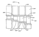
図9Aおよび9Bは、TEシステム900のこのような実施の形態を示したもので、熱交換器は、ピン以外のフィンを有している。図9Aは側面図であり、図9Bは図9Aを端面から見た側面図である。図9A、9Bに示したように、TEエレメントアレイ901は、複数のTEエレメント904をサンドイッチしているホット側基板902およびコールド側基板903を使用して構成されている。複数の熱交換器905が、ホット側基板902およびコールド側基板903の両方に、それらの基板を介して、TEエレメント904と良好に熱接触している。TEエレメント904間は、基板902、903およびTEエレメント904に接合された回路908を介して電気的に接続されていることが好ましい。
9A and 9B illustrate such an embodiment of a
図9A、9Bに示したように、熱交換器905は、基板902または903を介して、TEエレメント904(ホット側およびコールド側)と良好に熱接触した波形の薄い金属フィン906を備えている。熱交換器905は、基板902および903と接触する部分の面積が大きくなるように、可能な限り平らな底部エッジ907を有する、熱伝導率が大きい銅またはその他の材料で構成されていることが好ましい。流れ方向(図9Bの平面に直角の方向)の熱伝導率は、この実施の形態では、ギャップ909によって分離されたTEエレメント904の列毎に別個の熱交換器905を設けることによって最小化されている。
As shown in FIGS. 9A and 9B, the
図9Cは、別の実施の形態に係るTEシステム920を示す図であり、ヒートパイプ925およびヒートシンク926を使用した例を示す側面図である。TEエレメントアレイ921は、複数のTEエレメント924をサンドイッチしているホット側基板922およびコールド側基板923を使用して構成されている。この場合、TEシステム920は冷却用として構成されている。この場合も、コールド側基板923の熱伝導率は、流れ方向で小さくなっている。複数のヒートパイプ925は、一方の端面がコールド側基板923を介してTEエレメント924と良好に熱接触し、もう一方の端面が例示した熱交換機926に接触しており、コールド側基板923と、熱交換器926との間で熱が伝達されるようになっている。この実施の形態では、流れの方向は、図9Cの下から上に向かう方向である。図9Cに示したTEシステム920の場合、ホット側基板922は、ヒートシンク926と良好に熱接触している。TEシステム920によって生成される熱の観点から、事実上、ヒートシンク926はインフィニットであることが好ましい。
FIG. 9C is a diagram showing a
また、図に示すTEシステム920には、流れ方向で抵抗が変化するTEエレメント924が使用されている。最も抵抗の小さいエレメント927が流入側929に置かれ、最も抵抗の大きいエレメント928が流出側930に置かれている。この場合、抵抗は、TEエレメント924の断面積に反比例し、断面積は、流入側929から流出側930へ向かって減少しているため、抵抗は、逆に流出側930から流入側929へ向かって増加している。TEエレメント924は、上記のように、回路に電気的接続されているが、分かり易くするために、図9Cには示されていない。
The
図9Dおよび9Eは、さらに別の実施の形態に係る冷却用分離エレメントTEシステム940を示す図である。図9Eは側面図であり、図9Dは図9Eを端面から見た図である。図9D、9Eに示した構造は、フィン付き熱交換器945を製造するための好ましい方法の1つを示している。図に示したように、TEエレメントアレイ941は、ホット側基板942およびコールド側基板943を使用して構成されている。少なくともコールド側基板943は、流れ方向に小さい熱伝導率を有している。上記のように、回路949にまとめて電気的に接続された複数のTEエレメント944は、これらの基板942および943によりサンドイッチされている。
9D and 9E are diagrams showing a cooling separation
単一のフィンアレイ(フィン付き熱交換器)945は、コールド側基板943を介して、TEエレメント944と良好に熱接触している。単一片であるにもかかわらず、流れ方向におけるフィンアレイ945の熱伝導率は、隣接するフィンセクション間のギャップ946によって小さくなっている。タブ947は、アレイ全体を1つに保持している。これらのタブ947は、それらが、隣接するフィンセクション間の熱伝達を著しく大きくしないよう、ギャップ946と比較して十分に小さいことが好ましい。
A single fin array (heat exchanger with fins) 945 is in good thermal contact with the
図9Eは、流れが流入側950から流出側951へ進むに伴って、TEエレメント944の長さを増加させ、TEエレメント944の抵抗変化にることによる改善を示した図である。既に示した実施の形態の場合と同様に、抵抗の変化は、他の方法、例えばTEエレメント944の断面を変化させること、TEエレメント材料の抵抗率を変化させること、またはTEエレメントの長さ、断面および抵抗率が相違するものの組合せによって達成することができる。なお、ヒートシンク948は、ホット側基板942と良好に熱接触している。図7Eおよび図9Cには、これらのヒートシンクの好ましいタイプを示した。
FIG. 9E shows an improvement by increasing the length of the
図10は、別の実施の形態に係るTEシステムを示す図であり、流れ方向におけるTEエレメントの抵抗変化(および分離エレメント)によって、既に説明した性能向上と同様の性能向上を達成することができるシステムを示す側面図である。この実施の形態では、TEエレメントの抵抗は、デバイス全体を通して同じであるが、TEエレメントに印加される電圧が、流れ方向で変化している。 FIG. 10 is a diagram showing a TE system according to another embodiment, and a performance improvement similar to the performance improvement described above can be achieved by the resistance change (and separation element) of the TE element in the flow direction. It is a side view which shows a system. In this embodiment, the resistance of the TE element is the same throughout the device, but the voltage applied to the TE element varies in the flow direction.
図10には、TEシステム1000に係る一実施の形態が示されている。TEエレメントアレイ1001は、複数のTEエレメント1004をサンドイッチしているホット側基板1002およびコールド側基板1003を使用して構成されている。複数の熱交換器1005が、ホット側基板1002およびコールド側基板1003の両方に、それらの基板を介して、TEエレメント1004と良好に熱接触している。熱交換器1005および基板1002、1003は、既に説明した実施の形態に示す任意の構成にすることができる。熱交換器1005は、図9Aおよび9Bに示した熱交換器と同様、基板1002または1003を介して、TEエレメント1004(ホット側1011、コールド側1010)と良好に熱接触している。図10に示したように、ホット側1011およびコールド側1010の流れは、いずれも左から右である。
FIG. 10 shows an embodiment according to the
流体1009は、周囲環境温度TAで左側から流入し、熱交換器1005を迂回して、または熱交換器を通って、TEシステム1000の全長さにわたって徐々に温度変化しながら流れ、コールド側では、TCに温度が低下した流体1010として右側から流出し、ホット側では、THに温度が上昇した流体1011として右側から流出する。TEエレメントとTEエレメントとの間は、基板1002、1003およびTEエレメント1004に接続された回路1008を介して電気的に接続されている。既に示した実施の形態の場合のような基板上における相互接続回路とは異なり、基板の回路1008は、すべてのTEエレメント1004を直列に接続していない。
The fluid 1009 flows from the left side at the ambient temperature T A , flows through the
図10では、回路1008は、個々のTEエレメント1004または流れ方向に対して直角方向を向いたTEエレメント1004の列が、電圧が異なる電源を有している。そのために、異なる電流がエレメントまたは列を流れるように構成されている。したがって、図10に示したように、熱電アレイ(TEエレメントアレイ)1001の様々なセグメント、すなわちセクションに、様々な制御電圧1020が印加される。本実施の形態では、TEシステムをモニタするために、制御システム1012に接合された複数のセンサ1013、1014および1015が設けられている。制御システム1012は、複数の制御電圧1020に接続され、TEエレメントアレイ1001内の異なるエレメントまたは列に供給される電流を制御している。
In FIG. 10, the
TEシステム1000の長さ方向の電圧は、外部の状態に応じて、またはシステム自体の内部の状態に応じて、制御システム1012を介して変化させることができる。これらの状態には、そのうちのいくつか、またはすべてが存在する可能性がある、外部温度または流れ、内部温度または流れ、および個々のTEエレメントまたはTEエレメントの列による所望の加熱量または冷却量を手動で制御するためのユーザが選択可能な入力が含まれている。
The longitudinal voltage of the
外部温度または流れ、内部温度または流れなどの状態は、センサ1013および1014などを介してモニタされる。ユーザが選択可能な入力は、制御システム1012のノブ、ダイヤル、押しボタンまたは他のプログラム可能な手段により行われる。例えば、ユーザが選択可能な入力またはユーザが構成可能な入力用に、ユーザインタフェース1015が設けられている。モニタした状態、またはセンサ1013および1014を介してモニタした状態をトリップするレベルを、ユーザインタフェース1015を介して修正することにより、TEシステムの特定のアプリケーション、またはあらゆる時間にTEシステムが置かれる特定の条件に合わせて、TEシステムを個別化することが好ましい。センサ1013、1014および1015は、ハードワイヤードまたはソフトウェア関係(その性質は、アプリケーションによって異なる)を使用して、センサの入力に応じて印加電圧を変化させる制御回路1012によってモニタされている。
Conditions such as external temperature or flow, internal temperature or flow are monitored via
このタイプのシステムの利点は、効率改善を達成するために、TEエレメント1004によって生成される熱出力を、必要に応じて変化させることができることである。例えば、刻々と変化する流れの状態に応じて、TEエレメント1004を流れる電流を調整することができる。この実施の形態に係る効率利得を得るための能力は、TEシステムの長さ方向の任意のポイントxにおけるTEシステムの最適効率に対する電流Iopt(x)を求める下記の方程式(28)式によって理解することができる。
The advantage of this type of system is that the heat output generated by the
複数の熱交換器1105が、コールド側基板1103を介してTEエレメント1104と良好に熱接触している。図に示したように、この実施の形態における熱交換器1105は、図9Aおよび9Bに示した熱交換器905と同様であり、コールド側基板1103を介してTEエレメント1104と良好に熱接触している。上記のように、熱交換器1105は、釘、フィンまたはヒートパイプなどの多数の異なるタイプの熱交換器とすることができ、または任意の多数の他のタイプの熱交換器とすることができる。上記のように、TEエレメント1104は、コールド側1103を流体が流れる方向に、実質的に、または少なくとも効果的に熱的に分離されている。
A plurality of
ヒートシンク1114(TEシステム1100の観点から、実質的に、インフィニットである)は、ホット側基板1102を介してTEエレメント1104と良好に熱接触している。この実施の形態では、少なくともいくつか、場合によってはすべてのTEエレメント1104に、ピストン1107が設けられている。ピストンは孔1108を有しており、システムコントローラ1116に接続されたアクチュエータ1115に結合されている。システムコントローラ1116は、複数のセンサ1117、1118および1119と接続されている。例えば、センサは、外部センサ1117、内部センサ1118およびユーザ制御またはユーザ入力デバイス1119である。システムコントローラ1116は、ハードウェア、すなわちマイクロプロセッサをベースとしたコンピュータ制御をアクチュエータ1115に提供することが好ましく、アクチュエータ1115に必要な十分な電流を供給することができるように、アクチュエータ1115用の電源すなわちドライバを備えている。
The heat sink 1114 (substantially infinite from the point of view of the TE system 1100) is in good thermal contact with the
TEエレメントとTEエレメントとの間の電気的接続は、基板1102および1103に接続された回路1106によって図られ、かつ、回路1106は、TEエレメント1104の表面およびピストン1107とも接続されている。ピストン1107からホット側基板1102への電気的接続は、スライド接点1113を使用して達成されている。ピストン1107の中の孔1108により、液体TE材料1109は、ピストンが移動する際に孔1108を通過することができる。ピストン1107は、任意の位置で、液体TE材料を前方セクション1111と後方セクション1112とに分けている。この実施の形態では、ピストン1107は、導電率が液体TE材料1109の導電率より実質的に大きい導電材料で作製されている。
The electrical connection between the TE element and the TE element is achieved by a
ピストン1107がホット側回路1106まで完全に移動していない場合、すなわち後方セクション1112に体積が残存している状態では、液体TE材料1109の一部が、事実上、ピストン1107によって短絡される。それにより、TEエレメント1104の抵抗が、その最大抵抗よりある程度の値だけ小さくなる。したがって、固定スキームまたは時間変化スキームに従って、TEエレメント1104の抵抗がTEシステム1100の長さ方向に沿って変化するように、ピストン1107の位置を調整することができる。制御スキームは、図10に関連して説明したスキームと類似している。ただし、上記の制御スキームの場合には、TEエレメント1104に印加する電圧を変化させる代わりに、外部センサ1117、内部センサ1118、ユーザ入力センサ1119、または他の信号方式デバイスからの入力の変化に応答して、コントローラ1116または他の電源によって制御されるアクチュエータ1115を使用することにより、ピストン1107の位置を変更することが好ましい点が相違する。
If the
本技術において理解されるように、適切な磁界を印加することにより、特定のTE材料の性能を改善することができる。図12は、実施の形態に係るTEシステム1200一構成を示す側面図である。TEエレメント1204の材料構成は、磁界がTEエレメントのほぼ幅方向全体に印加されるようになっている。図12に示したように、TEエレメントアレイ1201は、複数のTEエレメント1204をサンドイッチしているホット側基板1202およびコールド側基板1203を使用して構成されている。熱交換器1205は、ホット側およびコールド側基板1202、1203を介して、TEエレメント1204と良好に熱接触している。図12に示したように、熱交換器1205は、図9Aおよび9Bに関連して説明した構成など、任意の適切な構成の熱交換器である。
As understood in the art, the performance of certain TE materials can be improved by applying an appropriate magnetic field. FIG. 12 is a side view showing a configuration of
この実施の形態においても、前述の実施の形態と同様、流れ方向におけるTEエレメント1204の実質的または効果的な熱的分離が採用されている。TEエレメントの直列電気接続は、ホット側およびコールド側基板1202、1203およびTEエレメント1204に接合または固定された回路1206によって達成されている。例えば、いくつかのTE材料に対して、永久磁石1207から適切な磁界が印加されている。永久磁石1207は、それらの極性(図12では、北はNで、また、南はSで示されている)が、すべて同じ方向に配向されている。したがって、磁界1208(点線で示す)は、TEエレメント1204の幅方向を貫通している。
In this embodiment, as in the previous embodiment, substantial or effective thermal separation of the
図13は、実施の形態に係るTEシステム1300の構成を示す側面図である。TEエレメント1304の材料構成は、TEエレメントの長さ方向全体に適切な磁界が印加されるようにすることによって、改善が図られている。図13に示したように、TEエレメントアレイ1301は、複数のTEエレメント1304をサンドイッチしているホット側基板1302およびコールド側基板1303を使用して構成されている。この実施の形態では、熱交換器1305は、永久磁石1307と良好に熱接触している。永久磁石1307は、コールド側基板1303を介してTEエレメント1304と良好に熱接触している。一つの実施の形態では、永久磁石が熱交換器を形成している。別法としては、熱交換器1305を、図9Aおよび9Bに関連して説明した熱交換器905と同様の熱交換器とすることもできる。
FIG. 13 is a side view showing the configuration of the
この実施の形態では、流れ方向におけるTEエレメント1304の実質的または効果的な熱的分離が採用されている。ヒートシンク1309(TEシステム1300の観点から、実質的にインフィニットである)は、ホット側基板1302を介してTEエレメント1304と良好に熱接触している。ヒートシンク1309は、鉄などの高透磁率材料で作製されている。TEエレメント1304の直列電気接続は、ホット側およびコールド側基板1302、1303およびTEエレメント1304に接合され、または取り付けられた回路1306によって達成されている。磁界は、対毎に極性(図13では、北はNで、また、南はSで示されている)を向き合わせて配向された永久磁石1307によって印加されている。磁気回路は、高透磁率のヒートシンク1309を介してホット側で完結している。したがって、磁界1308(点線で示す)は、実質的にTEエレメント1304の長さ方向を貫通している。
In this embodiment, substantial or effective thermal separation of the
上記の実施の形態では、熱を伝達する媒体または熱を抽出する媒体が、流体である。図14は、流体が固体に置換された構造を有するTEシステムを示す側面図である。図14に示したTEシステム1400は、複数のTEエレメント1404をサンドイッチしているホット側基板1402およびコールド側基板1403を使用して構成されたTEエレメントアレイ1401を備えている。ヒートシンク1409(TEシステム1400の観点から、実質的にインフィニットである)は、ホット側基板1402を介して、TEエレメント1404と良好に熱接触している。TEエレメント1404の直列電気接続は、ホット側およびコールド側基板1402、1403およびTEエレメント1404に接合され、または取り付けられた回路1407によって達成されている。
In the above embodiment, the medium that transfers heat or the medium that extracts heat is a fluid. FIG. 14 is a side view showing a TE system having a structure in which a fluid is replaced with a solid. The
冷却される固体材料1405(図に示すケースの場合)は、図14の左から右へ向かって移動し、コールド側基板1403を介してTEエレメント1404と良好に熱接触している。固体材料1405とコールド側基板1403との間の界面における良好な熱伝達率は、例えば、熱グリース1406によって達成されている。固体材料1405がコールド側基板1403に沿って通過すると、固体1405は、TEエレメント1404によって徐々に冷却される。固体に沿った移動方向ではなく、固体材料1405とTEエレメント1404との間は、基板1403およびグリース1406を介して良好な熱伝達率を有していることが好ましい。適切な固体材料1405は、複合材料(composites)または他の熱異方性材料がよい。また、例えば、固体材料1405の移動方向に対する直角方向にスロットが設けられ、そのスロットに熱絶縁体が充填されたものでもよい。
The
図15Aないし図15Gは、分離エレメントTEシステムの長さ方向における様々な温度プロファイルの例を示したグラフである。これらの図のすべてにおいて、ホット側の流れは、右側から左側として示され、また、コールド側の流れは、左側から右側として示されている。一方の側にヒートシンクを有しているケースでは、ヒートシンク側には流れが存在しない。ポイントOは常に左側にあり、コールド側の流れの流入端およびホット側の流れの流出端を表している。ポイントLは常に右側にあり、コールド側の流れの流出端およびホット側の流れの流入端を表している。水平線は、常に周囲環境温度TAを表している。 15A to 15G are graphs showing examples of various temperature profiles in the length direction of the separation element TE system. In all of these figures, the hot side flow is shown from right to left, and the cold side flow is shown from left to right. In the case of having a heat sink on one side, there is no flow on the heat sink side. Point O is always on the left and represents the cold flow inflow end and the hot flow outflow end. Point L is always on the right and represents the outflow end of the cold side flow and the inflow end of the hot side flow. Horizontal lines are always represents the ambient temperature T A.
図15Aは、ΔTC=ΔTHのケース、図15Bは、ΔTC>ΔTHのケース、図15Cは、ΔTC<ΔTHのケースを示したグラフである。図15Dは、ホット側にインフィニットヒートシンク(infinite heat sink)を有し、したがって、ΔTH=0のケース、図15Eは、コールド側にインフィニットヒートシンクを有し、したがって、ΔTC=0のケース、図15Fは、冷たい流体が温度TCIN<TAで流入するケースを示したグラフである。図15Gは、熱い流体が温度THIN>TAで流入するケースを示したグラフである。他の温度プロファイルも意図されており、また、デバイスは、本発明の教示に従って、ヒートシンク、流入温度および流出温度の可能なすべての組合せが生成されるように構成されている。 Figure 15A is a case of [Delta] T C = [Delta] T H, FIG. 15B, [Delta] T C> [Delta] T H of the case, FIG. 15C is a graph showing the case of ΔT C <ΔT H. FIG. 15D has an infinite heat sink on the hot side and therefore ΔT H = 0, FIG. 15E has an infinite heat sink on the cold side and therefore ΔT C = 0, FIG. 15F is a graph showing a case where cold fluid flows at a temperature T CIN <T a. Figure 15G is a graph showing a case in which hot fluid flows at a temperature T HIN> T A. Other temperature profiles are also contemplated, and the device is configured to produce all possible combinations of heat sinks, inlet temperatures and outlet temperatures in accordance with the teachings of the present invention.
デュアルモード動作の場合、理想化された方程式(9)式は、冷却モードのCOPが最適化されると、加熱モードのCOPも最適化されるが、流量、TEエレメント抵抗値対位置の変化、またはTEエレメント電流値対位置の変化は、もはやそのアプリケーションには適切ではないことを示している。熱電気の基本方程式によって導かれるこれらのパラメータを調整することにより、システム全体の性能を最適化することができる。 For dual mode operation, the idealized equation (9) shows that if the COP in the cooling mode is optimized, the COP in the heating mode is also optimized, but the change in flow rate, TE element resistance versus position, Or a change in TE element current value versus position indicates that it is no longer appropriate for the application. By adjusting these parameters derived by the basic thermoelectric equations, the overall system performance can be optimized.
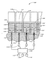
図16は、別の実施の形態に係るTEシステム1600を示す側面図およびグラフである。排出側の流れが、セクション1609内のTEエレメントアレイ1601の長さ方向を通り抜けている。既に示した実施の形態の場合と同様、TEエレメントアレイ1601は、複数のTEエレメント1604をサンドイッチしているホット側基板1602およびコールド側基板1603を使用して構成されている。複数のピン1605が、ホット側基板1602およびコールド側基板1603の両方に、それらの基板を介して、TEエレメント1604と良好に熱接触し、TEシステム1600の熱交換器を形成している。図16に示したように、ピン1605は、釘に極めて類似した形状を有しており、そのヘッドは、TEエレメント1604(ホット側およびコールド側)と良好に熱接触している。ピン1605は、熱伝導率の大きい銅または他の材料でできていることが好ましい。ピン1605は、アプリケーションまたは熱の伝達が行われる流体に応じて、既にいくつかについて説明した他の熱交換器の構成または幾何学に置き換えることができる。
FIG. 16 is a side view and graph showing a
ホット側基板1602、コールド側基板1603および回路1606の構造は、図7Aないし7Cに関連して説明した構造と同じであり、TEアレイ1601の長さ方向におけるTEエレメント1604の熱的な分離特性を維持している。ホット側ダクト1607は、流体が、温度TAで左側から流入し、ホット側の熱交換器1605を通過して温度THで右側から流出するように、TEシステム1600のホット側に取り付けられている。また、複数のダクト1608がTEシステム1600のコールド側に取り付けられており、流体が、熱交換器1605の複数のセクション1609を通過して流れるようになっている。
The structures of the hot-
温度TAの流体が、左側の2つのダクト1608のそれぞれ左端から流入し、それぞれ右端から流出する。温度TAの流体が、最も右側のダクト1608の右端から流入し、その左端から流出する。図16には、図に示す実施の形態の排出側であるコールド側に3つのセクション1609が示されているが、セクションの数は任意であり、また、すべて同じ長さである必要はなく、または同じ方向に流れる必要もない。コールド側の出口温度TC1、TC2等は、同じ温度にする必要はなく、また、各々を通過する流体の量も同じである必要はない。
A fluid of temperature T A flows in from the left ends of the two
コールド側の空気は、温度TAで、TEシステム1600の長さ方向の複数のポイントで導入されるため、TEエレメント1604の両端間のΔTは、コールド側の空気が、排出されるのに先だって、コールド側のすべての熱交換器1605を通過する場合のΔTよりも小さい。(10)式で示したように、ΔTが小さくなるとCOPが大きくなるため、TEシステム1600のホット側は、単一のコールド側ダクトを備えている場合よりも温かくなる。図16の下側に示したグラフは、これを温度プロファイルで示したものである。
Since the cold side air is introduced at multiple points along the length of the
温度TAの流体の各導入ポイント(ポイント0、L1、L2...)では、前のセクションのCOPは、比較的小さくなっている。温度TAの新しい流体により、新しい流体が導入されるステージのCOPが大きくなり、それにより、そのセクション全体の追加ΔTが達成される。一般的に、各セクションによって付加される正味のΔTは、後続のステージ(L2等)で導入される流体の温度がTAより高くない限り、デバイスの長さに従って漸減すること、すなわち後続のステージにおけるヒートシンク性能が極めて高いことに留意されたい。 At each point of introduction of fluid at temperature T A (points 0, L 1 , L 2 ...), The COP of the previous section is relatively small. The new fluid at temperature T A increases the COP of the stage where the new fluid is introduced, thereby achieving an additional ΔT for the entire section. In general, the net ΔT added by each section will gradually decrease according to the length of the device unless the fluid temperature introduced in subsequent stages (such as L 2 ) is higher than T A , ie the subsequent Note that the heat sink performance at the stage is extremely high.
図16に示した実施の形態は、加熱モードにおけるTEシステムの動作を示したものである。これと同じ手法を使用して、同様に冷却モードで構成された、排出側の流体が複数のポイントから流入するTEシステムの性能を向上させることができる。 The embodiment shown in FIG. 16 shows the operation of the TE system in the heating mode. This same approach can be used to improve the performance of a TE system that is similarly configured in a cooling mode and in which exhaust fluid flows in from multiple points.
図17は、別の実施の形態に係るTEシステム1700を示す側面図およびグラフである。排出側(冷却側)の流れが、セクション1709内のTEアレイ1701の長さ方向を通り抜けている。図17は、TEシステム1700の反対側の端部からの流れである点で、図16と異なっている。TEエレメントアレイ1701は、図16の場合と全く同様に、ホット側基板1702、コールド側基板1703、複数のピン(熱交換器)1705、回路1706、ホット側ダクト1707、および熱交換器1705の複数のセクション1709に対応する複数のダクト1708を使用して構成されている。
FIG. 17 is a side view and a graph showing a
図17に示した実施の形態に係るTEシステムは、この場合も加熱モードで動作している。これと同じ手法を使用して、同様に冷却モードで構成された、排出側の流体が複数のポイントから流入するTEシステムの性能を向上させることができる。また、排出側流体のすべてが同じ方向に、同じ温度で流入する必要はなく、また、同じ間隔、すなわち同じ長さのセクションに流入し、または流体の流量が同じである必要もない。 The TE system according to the embodiment shown in FIG. 17 is also operating in the heating mode in this case. This same approach can be used to improve the performance of a TE system that is similarly configured in a cooling mode and in which exhaust fluid flows in from multiple points. Also, it is not necessary for all of the discharge side fluid to flow in the same direction and at the same temperature, nor does it flow into sections of the same spacing, i.e., the same length, or the flow rate of the fluid.
図18は、他の実施の形態に係るTEシステム1800を示す側面図およびグラフである。排出側の流れが、TEエレメントアレイ1801の長さ全体を通り抜けていない。TEエレメントアレイ1801は、図16の場合と全く同様に、ホット側基板1802、コールド側基板1803および複数のピン1805を使用して構成されている。ホット側ダクト1807は、流体が、温度TAで左側から流入し、ホット側の熱交換器1805を通過して温度THで右側から流出するように、TEシステム1800のホット側に取り付けられている。ダクト1808が、TEシステム1800のコールド側に取り付けられており、流体が、熱交換器1805を通過して流出するようになっている。
FIG. 18 is a side view and a graph showing a
温度TAの流体が、図の左端からコールド側ダクト1808に流入する。バルブ1809は、2つの位置を有しており、一方の位置(開位置)で、流体がダクト1808全体を通って流れ、温度TCで右端1811から流出する。バルブ1809のもう一方の位置(閉位置)では、流体はダクト1808の一部のみを通って流れ、温度TC *で中間位置1810から流出する。図18には、2つのセクション1812が示されているが、セクションの数は任意であり、また、必ずしも同じ長さである必要はなく、また、流体の流れを同じ方向にする必要も、または同じ温度で流入させる必要もない。
A fluid of temperature T A flows into the
図18の下側に示した曲線1820および1821(長い点線)は、バルブ1809が開位置にあり、TEシステム1800に若干のΔTを生成させる必要がある場合の温度プロファイルである。出口ポイントL2では、コールド側曲線の勾配がゼロではないので、熱流がゼロではないことに留意されたい。したがって、この状況では、TEシステム1800は、依然としてコールド側から熱を除去し、かつ、依然として熱をホット側に引き渡している。バルブが依然として開位置にある状態で、TEシステム1800に大きなΔTを生成させる必要がある場合は、十分なΔTが発生するように、より多くの電力をTEエレメント1804に供給することにより、コールド側温度プロファイルが、概ね曲線1822および1823に従うようにしなければならない。中間ポイントL1のいずれかで、コールド側温度の勾配が事実上ゼロであることに留意されたい。
L1を通過した後、流れを継続させることができる場合、コールド側温度は、曲線1823(短い点線)に沿って継続する。バルブ1809が閉じており、したがって流体を出口ポイント1810に排出させている場合、事実上、熱損失を除くすべてのジュール加熱を利用して、ホット側温度プロファイル1824に従って、さらにホット側温度をTH *まで上昇させることができる。
If the flow can continue after passing L 1 , the cold side temperature continues along curve 1823 (short dotted line). Valve 1809 is closed, therefore if drained fluid to exit
また、TEアレイ1801の一部から流れを除去する手法を、対向する端部からの流れで構成されたデバイスに採用することもできる。さらに、バルブ1809および単一のコールド側ダクト1808を、複数のバルブおよびダクトに置き換えることもできる。
In addition, a method of removing a flow from a part of the
上記のすべての実施の形態には、図10および11に関連して説明したシステムコントローラと同様のシステムコントローラが存在している。これらの説明は、TEエレメントの電圧を調整するためのコントローラ(図10)およびピストンの位置を調整するためのコントローラ(図11)の使用に的が絞られている。また、コントローラには、例えば電流(TEエレメントが直列に接続されている場合)またはホット側流量またはコールド側流量を調整することができるように、ハードワイヤードまたはソフトウェア関係と共に、同じまたは類似の感覚入力からの情報が使用されている。その関係は、ルックアップテーブル、数式または他のアルゴリズムプロセスの形態になっている。したがって、このようなコントローラを使用することにより、総合効率を改善する機会が提供され、平均入力電力を小さくし、またはシステムの出力を変更することができる。 In all of the above embodiments, there is a system controller similar to the system controller described in connection with FIGS. These descriptions are focused on the use of a controller (FIG. 10) for adjusting the voltage of the TE element and a controller (FIG. 11) for adjusting the position of the piston. The controller also has the same or similar sensory inputs, along with hardwired or software relationships, so that, for example, current (when TE elements are connected in series) or hot flow or cold flow can be adjusted Information from is used. The relationship is in the form of a lookup table, formula or other algorithm process. Thus, using such a controller provides an opportunity to improve the overall efficiency, and can reduce the average input power or change the output of the system.
図に示したコントローラには、複数のパラメータをモニタし、これらのパラメータに応答してシステムを動的に調整する可能性が意図されている。このコントロールシステムは、例えばユーザによって制御されるスイッチなどの極めて単純なシステムである。例えば、コントロールシステムは、冷却から加熱へ変化させるために、熱電システムに流れる電流を反転させ、または温度が高すぎること、または低すぎることを決定する人間による感覚入力を使用して電流の量を動的に調整し、それにより冷却量または加熱量を変化させることを目的として、電流を交番させるためのスイッチそのものである。 The controller shown in the figure is intended for the possibility of monitoring a plurality of parameters and dynamically adjusting the system in response to these parameters. This control system is a very simple system such as a switch controlled by a user. For example, the control system reverses the current flowing through the thermoelectric system to change from cooling to heating, or uses a human sensory input to determine whether the temperature is too high or too low, A switch for alternating current for the purpose of dynamically adjusting and thereby changing the amount of cooling or heating.
以上の説明では、TEエレメントの各列の長さ、面積、抵抗率または印加電力の変更が提案されている。製造性、単純性およびコストの面から、TEエレメントのグループは同一であるか、またはサブモジュールとして構成されている。したがって、すべての列を異なったものにする必要はない。このような単純化にもかかわらず、なおかつ効率が改善され、その改善は、どれだけ多くの様々なサイズ、電力、レベル等を使用するかに依存している。 In the above description, changing the length, area, resistivity, or applied power of each column of TE elements is proposed. From the standpoint of manufacturability, simplicity and cost, the TE element groups are identical or are configured as submodules. Thus, it is not necessary for every column to be different. Despite this simplification, there is still an improvement in efficiency, which depends on how many different sizes, powers, levels, etc. are used.
ヒートシンクが使用されている上述の実施の形態の場合、ヒートシンクをヒートパイプまたは他の熱移送メカニズムに置き換えることができる。したがって、ヒートシンクまたは類似の手段を離して配置することができ、またはアセンブリを、排出熱出力を抽出する1つまたは複数の他のアセンブリにリンクさせることができる。また、冷却または加熱される媒体として流体および固体について説明したが、スラリーなどの流体と固体の組に合わせも、冷却または加熱すべき媒体として可能である。最後に、効率を改善するための様々な方法について、熱的な分離機能と組み合わせて説明したが、個々のアプリケーションに適切である場合、効率を改善するための、例えば抵抗変化、電流変化、および上記のその他の方法は、組み合わせて一体として使用することができ、または単独でも使用することができる。 In the embodiment described above where a heat sink is used, the heat sink can be replaced with a heat pipe or other heat transfer mechanism. Thus, a heat sink or similar means can be placed remotely, or the assembly can be linked to one or more other assemblies that extract the exhaust heat output. Moreover, although the fluid and the solid have been described as the medium to be cooled or heated, the medium to be cooled or heated can be combined with a combination of a fluid and a solid such as slurry. Finally, various methods for improving efficiency have been described in combination with thermal isolation functions, but when appropriate for individual applications, for example, resistance changes, current changes, and The other methods described above can be combined and used as one piece, or can be used alone.
上述の実施の形態は、コールド側すなわちTEシステムの冷却特性の考察に的を絞って示したものである。このようなデバイスに流れる電流の方向を反転させることによって、または出力をホット側からコールド側へ反転させることによって、加熱または加熱と冷却を、同じまたは類似の構成で提供することができる。あらゆる特定な用途に対する最適化は、TEシステムの個々のアプリケーションに応じて様々であるが、個々のアプリケーションには、以下に列記するいくつかの潜在的な相違が生じる。
1)自動車用、家庭用および産業用加熱システムの場合、加熱モードでは、例えば必要なΔTHは、実質的にΔTCより大きい。
2)性能を最適化するためには、マスフロー比率(排出側に対するメイン側)の調整が必要である。
3)今日のTE熱ポンピング出力の能力により、デバイスの両端間のΔTが約70℃に制限されているため、COPの大きい高ΔTHを達成するには、あらゆる特定のアプリケーションによる要求に応じて、構成およびフローパターンを調整しなければならない。
4)要求に応じて、加熱モードまたは冷却モードのいずれかでシステムを動作させる必要がある場合、両方のモードで効果的に動作するように、十分フレキシブルに設計(HVACまたは熱ポンプシステム)することが好ましい。
The above-described embodiment is focused on the consideration of cooling characteristics of the cold side, that is, the TE system. By reversing the direction of the current flowing through such a device, or by reversing the output from the hot side to the cold side, heating or heating and cooling can be provided in the same or similar configuration. The optimization for any particular application will vary depending on the particular application of the TE system, but individual applications will have some potential differences listed below.
1) For automotive, household and industrial heating systems, in the heating mode, for example, the required ΔT H is substantially greater than ΔT C.
2) In order to optimize the performance, it is necessary to adjust the mass flow ratio (main side with respect to the discharge side).
3) Due to the ability of today's TE thermal pumping power, the ΔT across the device is limited to about 70 ° C., so to achieve a high COP high ΔT H, as required by any particular application The configuration and flow pattern must be adjusted.
4) If required to operate the system in either heating mode or cooling mode as required, be designed to be sufficiently flexible (HVAC or heat pump system) to operate effectively in both modes Is preferred.
Claims (17)
冷却側および加熱側を備えた熱電アレイを形成するとともに、少なくともそのいくつかが、前記熱電アレイに沿った少なくとも1つの方向において、相互に実質的に熱的に分離された複数の熱電エレメントと、
少なくとも前記冷却側および/または前記加熱側で、少なくとも1つの前記熱電エレメントと熱的に接触し、前記熱電エレメントの熱的な分離を有効に維持するように構成された少なくとも1つの熱交換器とを備え、
少なくとも1つの前記熱交換器が複数の部分で構成され、複数の前記熱電エレメントのうちの1つの熱電エレメントが、少なくとも1つの前記部分と熱的に接触しており、前記部分が、前記媒体が移動する方向で、相互に実質的に熱的に分離されていることを特徴とする熱電システム。A thermoelectric system using at least one medium to be cooled or heated, comprising:
A plurality of thermoelectric elements forming a thermoelectric array with a cooling side and a heating side, at least some of which are substantially thermally separated from each other in at least one direction along the thermoelectric array;
At least one heat exchanger configured to be in thermal contact with at least one of the thermoelectric elements at least on the cooling side and / or the heating side and to effectively maintain thermal isolation of the thermoelectric elements; With
At least one of the heat exchangers is composed of a plurality of parts, one thermoelectric element of the plurality of thermoelectric elements is in thermal contact with at least one of the parts, and the part comprises the medium A thermoelectric system characterized in that it is substantially thermally separated from each other in the direction of movement .
冷却側および加熱側を備えた熱電アレイ内に、複数の熱電エレメントを形成するとともに、複数の前記熱電エレメントを、前記熱電アレイの少なくとも1つの方向において、相互に実質的に熱的に分離させるステップと、
複数の部分で構成された少なくとも1つの熱交換器を提供するステップであって、複数の前記熱電エレメントのうちの1つの熱電エレメントが、少なくとも1つの前記部分と熱的に接触し、前記部分が、媒体が移動する方向で、相互に実質的に熱的に分離するように構成するステップと、
前記熱電エレメントの熱的な分離が有効に維持されている状態で、前記熱電アレイの少なくとも一方の側で熱交換が行われるようにするステップとを含むことを特徴とする熱電システムの製造方法。A method of manufacturing an improved thermoelectric system using at least one medium that is cooled or heated, comprising:
Forming a plurality of thermoelectric elements in a thermoelectric array having a cooling side and a heating side and substantially thermally separating the plurality of thermoelectric elements from each other in at least one direction of the thermoelectric array; When,
Providing at least one heat exchanger comprised of a plurality of parts, wherein one of the plurality of thermoelectric elements is in thermal contact with at least one of the parts, Configuring the media to move substantially thermally from one another in the direction of movement;
And a step of performing heat exchange on at least one side of the thermoelectric array in a state where thermal separation of the thermoelectric elements is effectively maintained.
Applications Claiming Priority (3)
| Application Number | Priority Date | Filing Date | Title |
|---|---|---|---|
| US26765701P | 2001-02-09 | 2001-02-09 | |
| US09/844,818 US6539725B2 (en) | 2001-02-09 | 2001-04-27 | Efficiency thermoelectrics utilizing thermal isolation |
| PCT/US2002/003772 WO2002065030A1 (en) | 2001-02-09 | 2002-02-07 | Improved efficiency thermoelectrics utilizing thermal isolation |
Publications (3)
| Publication Number | Publication Date |
|---|---|
| JP2004526930A JP2004526930A (en) | 2004-09-02 |
| JP2004526930A5 JP2004526930A5 (en) | 2005-12-22 |
| JP4041972B2 true JP4041972B2 (en) | 2008-02-06 |
Family
ID=26952545
Family Applications (1)
| Application Number | Title | Priority Date | Filing Date |
|---|---|---|---|
| JP2002564308A Expired - Fee Related JP4041972B2 (en) | 2001-02-09 | 2002-02-07 | Thermoelectric system with improved efficiency using thermal separation |
Country Status (9)
| Country | Link |
|---|---|
| US (2) | US6539725B2 (en) |
| EP (2) | EP1366328B1 (en) |
| JP (1) | JP4041972B2 (en) |
| KR (1) | KR100860015B1 (en) |
| CN (1) | CN100427849C (en) |
| AT (2) | ATE404830T1 (en) |
| DE (2) | DE60239840D1 (en) |
| RU (1) | RU2315250C2 (en) |
| WO (1) | WO2002065030A1 (en) |
Families Citing this family (194)
| Publication number | Priority date | Publication date | Assignee | Title |
|---|---|---|---|---|
| US6606866B2 (en) * | 1998-05-12 | 2003-08-19 | Amerigon Inc. | Thermoelectric heat exchanger |
| US6327841B1 (en) * | 1999-11-16 | 2001-12-11 | Utilx Corporation | Wire rope lubrication |
| US6539725B2 (en) * | 2001-02-09 | 2003-04-01 | Bsst Llc | Efficiency thermoelectrics utilizing thermal isolation |
| US7942010B2 (en) | 2001-02-09 | 2011-05-17 | Bsst, Llc | Thermoelectric power generating systems utilizing segmented thermoelectric elements |
| US7273981B2 (en) * | 2001-02-09 | 2007-09-25 | Bsst, Llc. | Thermoelectric power generation systems |
| US6959555B2 (en) * | 2001-02-09 | 2005-11-01 | Bsst Llc | High power density thermoelectric systems |
| US7231772B2 (en) * | 2001-02-09 | 2007-06-19 | Bsst Llc. | Compact, high-efficiency thermoelectric systems |
| US7946120B2 (en) | 2001-02-09 | 2011-05-24 | Bsst, Llc | High capacity thermoelectric temperature control system |
| US6672076B2 (en) | 2001-02-09 | 2004-01-06 | Bsst Llc | Efficiency thermoelectrics utilizing convective heat flow |
| US7386589B1 (en) | 2001-04-05 | 2008-06-10 | Remote Sales, Llc | Managed messaging platform with message response aggregation |
| US7533187B1 (en) * | 2001-04-05 | 2009-05-12 | Marcellino Tanumihardja | Wireless device detection |
| KR20040008155A (en) * | 2001-04-09 | 2004-01-28 | 리써치 트라이앵글 인스티튜트 | Thin-film thermoelectric cooling and heating devices for dna genomic and proteomic chips, thermo-optical switching circuits, and ir tags |
| US8490412B2 (en) * | 2001-08-07 | 2013-07-23 | Bsst, Llc | Thermoelectric personal environment appliance |
| CN100419347C (en) * | 2001-08-07 | 2008-09-17 | Bsst公司 | Thermoelectric personal environment appliance |
| JP2005506693A (en) * | 2001-10-05 | 2005-03-03 | リサーチ・トライアングル・インスティチュート | Phonon blocking electron transfer low dimensional structure |
| JP2003124531A (en) * | 2001-10-11 | 2003-04-25 | Komatsu Ltd | Thermoelectric module |
| US6812395B2 (en) | 2001-10-24 | 2004-11-02 | Bsst Llc | Thermoelectric heterostructure assemblies element |
| JP4472359B2 (en) * | 2002-04-15 | 2010-06-02 | ネクストリーム・サーマル・ソリューションズ・インコーポレーテッド | Thermoelectric device using double-sided Peltier junction and manufacturing method thereof |
| US6893086B2 (en) * | 2002-07-03 | 2005-05-17 | W.E.T. Automotive Systems Ltd. | Automotive vehicle seat insert |
| US20110209740A1 (en) * | 2002-08-23 | 2011-09-01 | Bsst, Llc | High capacity thermoelectric temperature control systems |
| US6857697B2 (en) * | 2002-08-29 | 2005-02-22 | W.E.T. Automotive Systems Ag | Automotive vehicle seating comfort system |
| US20040055292A1 (en) * | 2002-09-20 | 2004-03-25 | Claudio Filipppone | AlphaCor alpha powered miniaturized power plant |
| DE10259648B4 (en) * | 2002-12-18 | 2006-01-26 | W.E.T. Automotive Systems Ag | Air-conditioned seat and air conditioning device for a ventilated seat |
| US7356912B2 (en) * | 2003-09-25 | 2008-04-15 | W.E.T. Automotive Systems, Ltd. | Method for ventilating a seat |
| US7274007B2 (en) | 2003-09-25 | 2007-09-25 | W.E.T. Automotive Systems Ltd. | Control system for operating automotive vehicle components |
| US7370911B2 (en) * | 2003-10-17 | 2008-05-13 | W.E.T. Automotive Systems, Ag | Automotive vehicle seat insert |
| US7425034B2 (en) * | 2003-10-17 | 2008-09-16 | W.E.T. Automotive Systems Ag | Automotive vehicle seat having a comfort system |
| US7461892B2 (en) * | 2003-12-01 | 2008-12-09 | W.E.T. Automotive Systems, A.C. | Valve layer for a seat |
| US8455751B2 (en) * | 2003-12-02 | 2013-06-04 | Battelle Memorial Institute | Thermoelectric devices and applications for the same |
| US7851691B2 (en) | 2003-12-02 | 2010-12-14 | Battelle Memorial Institute | Thermoelectric devices and applications for the same |
| US20050139250A1 (en) * | 2003-12-02 | 2005-06-30 | Battelle Memorial Institute | Thermoelectric devices and applications for the same |
| US7834263B2 (en) * | 2003-12-02 | 2010-11-16 | Battelle Memorial Institute | Thermoelectric power source utilizing ambient energy harvesting for remote sensing and transmitting |
| JP2007518252A (en) | 2003-12-02 | 2007-07-05 | バッテル メモリアル インスティチュート | Thermoelectric device and its use |
| US7638705B2 (en) * | 2003-12-11 | 2009-12-29 | Nextreme Thermal Solutions, Inc. | Thermoelectric generators for solar conversion and related systems and methods |
| US7448222B2 (en) * | 2003-12-15 | 2008-11-11 | Bormann Ronald M | Thermoelectric refrigeration system |
| US20050150537A1 (en) * | 2004-01-13 | 2005-07-14 | Nanocoolers Inc. | Thermoelectric devices |
| JP2005299417A (en) * | 2004-04-07 | 2005-10-27 | Toyota Motor Corp | Exhaust heat power generating device and automobile equipped with the same |
| US7380586B2 (en) | 2004-05-10 | 2008-06-03 | Bsst Llc | Climate control system for hybrid vehicles using thermoelectric devices |
| US7129501B2 (en) * | 2004-06-29 | 2006-10-31 | Sii Nanotechnology Usa, Inc. | Radiation detector system having heat pipe based cooling |
| US20060076046A1 (en) * | 2004-10-08 | 2006-04-13 | Nanocoolers, Inc. | Thermoelectric device structure and apparatus incorporating same |
| US7523617B2 (en) * | 2004-10-22 | 2009-04-28 | Nextreme Thermal Solutions, Inc. | Thin film thermoelectric devices for hot-spot thermal management in microprocessors and other electronics |
| US8063298B2 (en) * | 2004-10-22 | 2011-11-22 | Nextreme Thermal Solutions, Inc. | Methods of forming embedded thermoelectric coolers with adjacent thermally conductive fields |
| US20060158011A1 (en) * | 2004-11-02 | 2006-07-20 | W.E.T. Automotive Systems Ag | Molded layer for a seat insert |
| US8024936B2 (en) * | 2004-11-16 | 2011-09-27 | Halliburton Energy Services, Inc. | Cooling apparatus, systems, and methods |
| US20060107989A1 (en) * | 2004-11-24 | 2006-05-25 | Marlow Industries, Inc. | High watt density thermoelectrics |
| US7699102B2 (en) * | 2004-12-03 | 2010-04-20 | Halliburton Energy Services, Inc. | Rechargeable energy storage device in a downhole operation |
| AU2005316870A1 (en) | 2004-12-03 | 2006-06-22 | Halliburton Energy Services, Inc. | Heating and cooling electrical components in a downhole operation |
| US7587901B2 (en) | 2004-12-20 | 2009-09-15 | Amerigon Incorporated | Control system for thermal module in vehicle |
| US7254953B2 (en) * | 2005-01-06 | 2007-08-14 | Caterpillar Inc | Thermoelectric heat exchange element |
| US20060150657A1 (en) * | 2005-01-10 | 2006-07-13 | Caterpillar Inc. | Thermoelectric enhanced HVAC system and method |
| EP1710017B1 (en) * | 2005-04-04 | 2012-12-19 | Roche Diagnostics GmbH | Thermocycling of a block comprising multiple samples |
| JP4581802B2 (en) * | 2005-04-05 | 2010-11-17 | 株式会社デンソー | Thermoelectric converter |
| US7743614B2 (en) | 2005-04-08 | 2010-06-29 | Bsst Llc | Thermoelectric-based heating and cooling system |
| WO2006110858A2 (en) * | 2005-04-12 | 2006-10-19 | Nextreme Thermal Solutions | Methods of forming thermoelectric devices including superlattice structures and related devices |
| DE102005018445B3 (en) * | 2005-04-20 | 2006-06-29 | W.E.T. Automotive Systems Ag | Air conditioning device for e.g. vehicle seat has air-conditioning zones, which are connected to recess by connecting device whereby recess allows the air to pass through it partially in transverse direction inspite of cover |
| US8039726B2 (en) * | 2005-05-26 | 2011-10-18 | General Electric Company | Thermal transfer and power generation devices and methods of making the same |
| US7847179B2 (en) * | 2005-06-06 | 2010-12-07 | Board Of Trustees Of Michigan State University | Thermoelectric compositions and process |
| WO2007002342A2 (en) | 2005-06-22 | 2007-01-04 | Nextreme Thermal Solutions | Methods of forming thermoelectric devices including electrically insulating matrixes between conductive traces and related structures |
| WO2007002337A2 (en) | 2005-06-22 | 2007-01-04 | Nextreme Thermal Solutions | Methods of forming thermoelectric devices including conductive posts and/or different solder materials and related methods and structures |
| WO2007032801A2 (en) * | 2005-06-28 | 2007-03-22 | Bsst Llc | Thermoelectric power generator for variable thermal power source |
| US8783397B2 (en) | 2005-07-19 | 2014-07-22 | Bsst Llc | Energy management system for a hybrid-electric vehicle |
| US7246496B2 (en) * | 2005-07-19 | 2007-07-24 | Visteon Global Technologies, Inc. | Thermoelectric based heating and cooling system for a hybrid-electric vehicle |
| US7478869B2 (en) | 2005-08-19 | 2009-01-20 | W.E.T. Automotive Systems, Ag | Automotive vehicle seat insert |
| US20090266084A1 (en) * | 2005-08-29 | 2009-10-29 | Rakesh Radhakrishnan | Thermoelectric device based refrigerant subcooling |
| CN101310372B (en) * | 2005-09-19 | 2011-07-13 | 开利公司 | Minimizing interface resistance through thermoelectric device by surface modification of thermoelectric material |
| US7365973B2 (en) | 2006-01-19 | 2008-04-29 | American Power Conversion Corporation | Cooling system and method |
| US8672732B2 (en) | 2006-01-19 | 2014-03-18 | Schneider Electric It Corporation | Cooling system and method |
| DE102006003816A1 (en) * | 2006-01-26 | 2007-08-02 | BSH Bosch und Siemens Hausgeräte GmbH | Domestic appliance, e.g. washing dryer, with thermoelectric heat pump, has several Peltier elements located in axially varying distribution to improve utilization of individual outputs |
| WO2007103249A2 (en) * | 2006-03-03 | 2007-09-13 | Nextreme Thermal Solutions | Methods of forming thermoelectric devices using islands of thermoelectric material and related structures |
| US7870745B2 (en) | 2006-03-16 | 2011-01-18 | Bsst Llc | Thermoelectric device efficiency enhancement using dynamic feedback |
| WO2007109368A2 (en) * | 2006-03-22 | 2007-09-27 | Leonardo Technologies, Inc. | Improved electric current carrying substrate for a thermoelectric module |
| US7952015B2 (en) | 2006-03-30 | 2011-05-31 | Board Of Trustees Of Michigan State University | Pb-Te-compounds doped with tin-antimony-tellurides for thermoelectric generators or peltier arrangements |
| FR2903481B1 (en) * | 2006-07-04 | 2015-05-15 | Joachim Baniakina | FLAT ELECTRONIC REFRIGERATOR |
| US7861538B2 (en) * | 2006-07-26 | 2011-01-04 | The Aerospace Corporation | Thermoelectric-based refrigerator apparatuses |
| US20080022695A1 (en) * | 2006-07-26 | 2008-01-31 | Welle Richard P | Input Power Control for Thermoelectric-Based Refrigerator Apparatuses |
| WO2008013946A2 (en) * | 2006-07-28 | 2008-01-31 | Bsst Llc | High capacity thermoelectric temperature control systems |
| EP2378577A3 (en) | 2006-07-28 | 2012-12-05 | Bsst Llc | Thermoelectric power generating systems utilizing segmented thermoelectric elements |
| US7788933B2 (en) * | 2006-08-02 | 2010-09-07 | Bsst Llc | Heat exchanger tube having integrated thermoelectric devices |
| US20100155018A1 (en) * | 2008-12-19 | 2010-06-24 | Lakhi Nandlal Goenka | Hvac system for a hybrid vehicle |
| US7779639B2 (en) * | 2006-08-02 | 2010-08-24 | Bsst Llc | HVAC system for hybrid vehicles using thermoelectric devices |
| US8222511B2 (en) * | 2006-08-03 | 2012-07-17 | Gentherm | Thermoelectric device |
| US8322155B2 (en) | 2006-08-15 | 2012-12-04 | American Power Conversion Corporation | Method and apparatus for cooling |
| US8327656B2 (en) | 2006-08-15 | 2012-12-11 | American Power Conversion Corporation | Method and apparatus for cooling |
| US9568206B2 (en) | 2006-08-15 | 2017-02-14 | Schneider Electric It Corporation | Method and apparatus for cooling |
| US8285149B2 (en) * | 2006-10-02 | 2012-10-09 | Futurewei Technologies, Inc. | Method and system for integrated DWDM transmitters |
| US8285150B2 (en) * | 2006-10-02 | 2012-10-09 | Futurewei Technologies, Inc. | Method and system for integrated DWDM transmitters |
| US8050525B2 (en) * | 2006-10-11 | 2011-11-01 | Futurewei Technologies, Inc. | Method and system for grating taps for monitoring a DWDM transmitter array integrated on a PLC platform |
| US20080087316A1 (en) | 2006-10-12 | 2008-04-17 | Masa Inaba | Thermoelectric device with internal sensor |
| US8285151B2 (en) * | 2006-10-20 | 2012-10-09 | Futurewei Technologies, Inc. | Method and system for hybrid integrated 1XN DWDM transmitter |
| US20080105213A1 (en) * | 2006-11-03 | 2008-05-08 | Chen Shih H | Air-Conditioning Device For Pet and Pet House Having The Same |
| DE102007027828A1 (en) * | 2006-11-14 | 2008-05-15 | Proseat Gmbh & Co.Kg | Module for cushioned object e.g. vehicle seat, has switching device partially corresponding with switching device of bolster unit, and cover covering bolster unit, where module and/or component part are foamed in carrier |
| US7739877B2 (en) * | 2006-12-06 | 2010-06-22 | Futurewei Technologies, Inc. | Method and system for redundant thermoelectric coolers for integrated DWDM transmitter/receiver |
| US20080142068A1 (en) * | 2006-12-18 | 2008-06-19 | American Power Conversion Corporation | Direct Thermoelectric chiller assembly |
| US7681404B2 (en) | 2006-12-18 | 2010-03-23 | American Power Conversion Corporation | Modular ice storage for uninterruptible chilled water |
| US8556009B2 (en) * | 2006-12-19 | 2013-10-15 | Bradley Wayne Bartilson | Safe, super-efficient, four-wheeled vehicle employing large diameter wheels with continuous-radius tires, with leaning option |
| US8100216B2 (en) * | 2006-12-19 | 2012-01-24 | Bradley Wayne Bartilson | Hybrid drivetrain with waste heat energy conversion into electricity |
| US7808214B2 (en) | 2006-12-19 | 2010-10-05 | Bradley Wayne Bartilson | Short-cycling serial hybrid drivetrain with high power density storage |
| US7805955B2 (en) * | 2006-12-30 | 2010-10-05 | Intel Corporation | Using refrigeration and heat pipe for electronics cooling applications |
| JP5485701B2 (en) * | 2007-01-10 | 2014-05-07 | ジェンサーム インコーポレイティド | Thermoelectric element |
| US8425287B2 (en) | 2007-01-23 | 2013-04-23 | Schneider Electric It Corporation | In-row air containment and cooling system and method |
| DK2147585T3 (en) | 2007-05-15 | 2017-01-16 | Schneider Electric It Corp | PROCEDURE AND SYSTEM FOR HANDLING EQUIPMENT AND COOLING |
| WO2008148042A2 (en) * | 2007-05-25 | 2008-12-04 | Bsst Llc | System and method for distributed thermoelectric heating and colling |
| US20080289677A1 (en) * | 2007-05-25 | 2008-11-27 | Bsst Llc | Composite thermoelectric materials and method of manufacture |
| US7765811B2 (en) * | 2007-06-29 | 2010-08-03 | Laird Technologies, Inc. | Flexible assemblies with integrated thermoelectric modules suitable for use in extracting power from or dissipating heat from fluid conduits |
| KR100859555B1 (en) * | 2007-07-09 | 2008-09-22 | 주식회사 하라시스템 | A active heat pipe used an thermionic element |
| US9105809B2 (en) * | 2007-07-23 | 2015-08-11 | Gentherm Incorporated | Segmented thermoelectric device |
| DE102007060312B4 (en) | 2007-08-24 | 2012-12-06 | W.E.T. Automotive Systems Ag | Electrothermal transducer and tempering device |
| WO2009036077A1 (en) | 2007-09-10 | 2009-03-19 | Amerigon, Inc. | Operational control schemes for ventilated seat or bed assemblies |
| US20090084421A1 (en) * | 2007-09-28 | 2009-04-02 | Battelle Memorial Institute | Thermoelectric devices |
| US7914271B2 (en) * | 2007-11-29 | 2011-03-29 | Husky Injection Molding Systems Ltd. | Gate insert heating and cooling |
| DE102007063171A1 (en) * | 2007-12-19 | 2009-06-25 | Deutsches Zentrum für Luft- und Raumfahrt e.V. | Thermoelectric module and thermoelectric generator |
| BRPI0906885A2 (en) * | 2008-01-14 | 2019-09-24 | The Ohio State University Research Foundation | thermoelectric materials and devices and methods of manufacture and use of thermoelectric devices |
| EP3121061B1 (en) | 2008-02-01 | 2020-03-11 | Gentherm Incorporated | Condensation and humidity sensors for thermoelectric devices |
| US7954331B2 (en) * | 2008-04-08 | 2011-06-07 | The Boeing Company | Thermally-balanced solid state cooling |
| EP2269240A2 (en) * | 2008-04-24 | 2011-01-05 | ZT Plus | Improved thermoelectric materials combining increased power factor and reduced thermal conductivity |
| CN102105757A (en) * | 2008-06-03 | 2011-06-22 | Bsst有限责任公司 | Thermoelectric heat pump |
| US20090323276A1 (en) * | 2008-06-25 | 2009-12-31 | Mongia Rajiv K | High performance spreader for lid cooling applications |
| AU2009270757B2 (en) | 2008-07-18 | 2016-05-12 | Gentherm Incorporated | Climate controlled bed assembly |
| US10667622B1 (en) | 2008-07-30 | 2020-06-02 | Youngblood Ip Holdings, Llc | Multi-zone temperature modulation system for bed or blanket |
| US9238398B2 (en) * | 2008-09-25 | 2016-01-19 | B/E Aerospace, Inc. | Refrigeration systems and methods for connection with a vehicle's liquid cooling system |
| US9447994B2 (en) | 2008-10-23 | 2016-09-20 | Gentherm Incorporated | Temperature control systems with thermoelectric devices |
| EP2349753B1 (en) * | 2008-10-23 | 2016-11-23 | Gentherm Incorporated | Multi-mode hvac system with thermoelectric device |
| US9555686B2 (en) | 2008-10-23 | 2017-01-31 | Gentherm Incorporated | Temperature control systems with thermoelectric devices |
| US20100101621A1 (en) * | 2008-10-28 | 2010-04-29 | Jun Xu | Solar powered generating apparatus and methods |
| US20100132380A1 (en) * | 2008-12-02 | 2010-06-03 | Direct Equipment Solutions Gp, Llc | Thermoelectric heat transferring unit |
| DE202009017049U1 (en) | 2008-12-21 | 2010-05-12 | W.E.T. Automotive Systems Ag | aerator |
| US8359871B2 (en) * | 2009-02-11 | 2013-01-29 | Marlow Industries, Inc. | Temperature control device |
| DE202010002050U1 (en) * | 2009-02-18 | 2010-07-15 | W.E.T. Automotive Systems Ag | Air conditioning device for vehicle seats |
| EP2419376A1 (en) * | 2009-04-13 | 2012-02-22 | The Ohio State University | Thermoelectric alloys with improved thermoelectric power factor |
| US8219362B2 (en) | 2009-05-08 | 2012-07-10 | American Power Conversion Corporation | System and method for arranging equipment in a data center |
| CN102576232B (en) | 2009-05-18 | 2015-05-06 | Bsst有限责任公司 | Temperature control system with thermoelectric device |
| EP2433321B1 (en) * | 2009-05-18 | 2014-10-22 | Bsst Llc | Battery thermal management system |
| US20110030754A1 (en) * | 2009-08-06 | 2011-02-10 | Laird Technologies, Inc. | Thermoelectric modules and related methods |
| DE102010004200A1 (en) | 2010-01-08 | 2011-07-14 | Emitec Gesellschaft für Emissionstechnologie mbH, 53797 | Device for generating electrical energy from a thermally conductive material |
| KR101395088B1 (en) | 2010-02-08 | 2014-05-16 | 한국전자통신연구원 | The thermoelectric array |
| WO2011112994A2 (en) | 2010-03-12 | 2011-09-15 | The Ohio State University | Thermoelectric figure of merit enhancement by modification of the electronic density of states |
| US9601677B2 (en) * | 2010-03-15 | 2017-03-21 | Laird Durham, Inc. | Thermoelectric (TE) devices/structures including thermoelectric elements with exposed major surfaces |
| DE102011014516A1 (en) | 2010-04-06 | 2012-05-10 | W.E.T. Automotive Systems Ag | MFP |
| US20110303197A1 (en) * | 2010-06-09 | 2011-12-15 | Honda Motor Co., Ltd. | Microcondenser device |
| DE102010024414A1 (en) | 2010-06-19 | 2011-12-22 | Volkswagen Ag | Electrothermal conversion |
| US9121414B2 (en) | 2010-11-05 | 2015-09-01 | Gentherm Incorporated | Low-profile blowers and methods |
| DE102010056170A1 (en) * | 2010-12-24 | 2012-06-28 | Volkswagen Ag | Thermoelectric heat exchange |
| US9478723B2 (en) | 2011-01-28 | 2016-10-25 | Nicholas F. Fowler | Dual path thermoelectric energy harvester |
| US8649179B2 (en) | 2011-02-05 | 2014-02-11 | Laird Technologies, Inc. | Circuit assemblies including thermoelectric modules |
| DE102011004243B4 (en) * | 2011-02-16 | 2015-02-19 | Eberspächer Exhaust Technology GmbH & Co. KG | exhaust manifold |
| EP2505913B1 (en) | 2011-03-30 | 2016-03-23 | Nxp B.V. | An active thermal management device and thermal management method |
| WO2012135734A2 (en) | 2011-04-01 | 2012-10-04 | Zt Plus | Thermoelectric materials having porosity |
| WO2012170443A2 (en) | 2011-06-06 | 2012-12-13 | Amerigon Incorporated | Cartridge-based thermoelectric systems |
| US9006557B2 (en) | 2011-06-06 | 2015-04-14 | Gentherm Incorporated | Systems and methods for reducing current and increasing voltage in thermoelectric systems |
| US20130000871A1 (en) * | 2011-06-30 | 2013-01-03 | Ian Olson | Systems and Methods for Extending Operating Temperatures of Electronic Components |
| US9799815B2 (en) * | 2011-09-06 | 2017-10-24 | Quantum Devices, Llc | Doped boron carbides and thermoelectric applications |
| WO2013052823A1 (en) | 2011-10-07 | 2013-04-11 | Gentherm Incorporated | Thermoelectric device controls and methods |
| DE102012020516A1 (en) | 2011-12-09 | 2013-06-13 | W.E.T. Automotive Systems Ag | Temperature control device for an electrochemical voltage source |
| WO2013095494A1 (en) | 2011-12-22 | 2013-06-27 | Schneider Electric It Corporation | System and method for prediction of temperature values in an electronics system |
| EP2795489A4 (en) | 2011-12-22 | 2016-06-01 | Schneider Electric It Corp | Analysis of effect of transient events on temperature in a data center |
| US9989267B2 (en) | 2012-02-10 | 2018-06-05 | Gentherm Incorporated | Moisture abatement in heating operation of climate controlled systems |
| ES2531450B2 (en) | 2012-05-30 | 2015-08-11 | Schweitzer Engineering Laboratories, Inc. | Thermal management of a communications transceiver in an electrical communications device |
| US9306143B2 (en) | 2012-08-01 | 2016-04-05 | Gentherm Incorporated | High efficiency thermoelectric generation |
| GB2525325B (en) * | 2012-11-26 | 2017-06-14 | Abb Technology Ag | System and method for energy harvesting in a data center |
| TWI454672B (en) * | 2012-12-20 | 2014-10-01 | Ind Tech Res Inst | Thermoelectric heat flow meter and thermoelectric transformation efficiency measure device |
| KR102253247B1 (en) | 2013-01-30 | 2021-05-17 | 젠썸 인코포레이티드 | Thermoelectric-based thermal management system |
| US9921007B2 (en) * | 2013-03-06 | 2018-03-20 | Bae Systems Plc | Laminated heat exchanger including a heat sink and a thermoelectric device |
| US9662962B2 (en) | 2013-11-05 | 2017-05-30 | Gentherm Incorporated | Vehicle headliner assembly for zonal comfort |
| CA2937164A1 (en) | 2014-01-16 | 2015-07-23 | Bi-Polar Holding Company, Llc | Heating and cooling system for a food storage cabinet |
| US9899589B2 (en) * | 2014-02-05 | 2018-02-20 | Panasonic Corporation | Thermal power generation unit and thermoelectric power generation system |
| KR102252584B1 (en) | 2014-02-14 | 2021-05-14 | 젠썸 인코포레이티드 | Conductive convective climate controlled assemblies |
| DE102014208433A1 (en) * | 2014-05-06 | 2015-11-26 | MAHLE Behr GmbH & Co. KG | Thermoelectric device, in particular for a motor vehicle |
| RU2576414C2 (en) * | 2014-05-21 | 2016-03-10 | Федеральное государственное бюджетное образовательное учреждение высшего профессионального образования "Курганский государственный университет" | Cooling device |
| DK3012568T3 (en) * | 2014-10-20 | 2018-12-10 | Abb Schweiz Ag | Cooling device and cooled electrical device comprising it |
| EP3726594B1 (en) | 2014-11-14 | 2022-05-04 | Gentherm Incorporated | Heating and cooling technologies |
| US11857004B2 (en) | 2014-11-14 | 2024-01-02 | Gentherm Incorporated | Heating and cooling technologies |
| US11639816B2 (en) | 2014-11-14 | 2023-05-02 | Gentherm Incorporated | Heating and cooling technologies including temperature regulating pad wrap and technologies with liquid system |
| WO2016100697A1 (en) | 2014-12-19 | 2016-06-23 | Gentherm Incorporated | Thermal conditioning systems and methods for vehicle regions |
| GB2540344A (en) * | 2015-07-06 | 2017-01-18 | Evontix Ltd | Control system |
| WO2017065847A1 (en) | 2015-10-14 | 2017-04-20 | Gentherm Incorporated | Systems and methods for controlling thermal conditioning of vehicle regions |
| EP3205956A1 (en) * | 2016-02-15 | 2017-08-16 | Anheuser-Busch InBev S.A. | Thermoelectric cooling apparatus |
| DE102016110625A1 (en) * | 2016-06-09 | 2017-12-14 | Eberspächer Exhaust Technology GmbH & Co. KG | Thermoelectric generator for exhaust systems and contact element for a thermoelectric generator |
| JP6597501B2 (en) * | 2016-07-04 | 2019-10-30 | 株式会社デンソー | Thermoelectric generator |
| US11607036B2 (en) | 2016-07-12 | 2023-03-21 | Bi-Polar Holding Company LLC | Food service apparatus with peltier heating and cooling systems |
| US10659168B2 (en) | 2016-08-23 | 2020-05-19 | Schweitzer Engineering Laboratories, Inc. | Low-power fiber optic transceiver |
| JP2019102527A (en) * | 2017-11-29 | 2019-06-24 | Joyson Safety Systems Japan株式会社 | Temperature control device and steering |
| JP2021522462A (en) | 2018-04-19 | 2021-08-30 | エンバー テクノロジーズ, インコーポレイテッド | Portable cooler with active temperature control |
| US11075331B2 (en) | 2018-07-30 | 2021-07-27 | Gentherm Incorporated | Thermoelectric device having circuitry with structural rigidity |
| KR102323978B1 (en) | 2018-08-21 | 2021-11-08 | 주식회사 엘지화학 | Thermoelectric module |
| CN109346595B (en) * | 2018-08-22 | 2023-02-17 | 江苏大学 | Stepped thermoelectric power generation sheet and pin height determination method thereof |
| KR20210095206A (en) | 2018-11-30 | 2021-07-30 | 젠썸 인코포레이티드 | Thermoelectric air conditioning system and method |
| EP3906383A2 (en) | 2019-01-11 | 2021-11-10 | Ember Technologies, Inc. | Portable cooler with active temperature control |
| US11152557B2 (en) | 2019-02-20 | 2021-10-19 | Gentherm Incorporated | Thermoelectric module with integrated printed circuit board |
| US11086081B2 (en) | 2019-03-21 | 2021-08-10 | Schweitzer Engineering Laboratories, Inc. | Conductive cooling for small form-factor pluggable (SFP) fiber optic transceivers |
| US11162716B2 (en) | 2019-06-25 | 2021-11-02 | Ember Technologies, Inc. | Portable cooler |
| US11668508B2 (en) | 2019-06-25 | 2023-06-06 | Ember Technologies, Inc. | Portable cooler |
| CA3143365A1 (en) | 2019-06-25 | 2020-12-30 | Ember Technologies, Inc. | Portable cooler |
| JP2023521040A (en) | 2020-04-03 | 2023-05-23 | エンバー ライフサイエンシズ, インコーポレイテッド | Portable cooler with active temperature control |
| CN113300634B (en) * | 2021-05-08 | 2022-06-21 | 江苏大学 | Two-stage thermoelectric power generation waste heat recovery device based on heat pipe heat transfer |
Family Cites Families (96)
| Publication number | Priority date | Publication date | Assignee | Title |
|---|---|---|---|---|
| US38128A (en) * | 1863-04-07 | Improvement in combined smut machine and separator | ||
| US3126116A (en) | 1964-03-24 | Check valveb nipple | ||
| GB817077A (en) * | 1956-08-22 | 1959-07-22 | Gen Electric | Improvements in or relating to thermoelectric cooling units |
| US36242A (en) * | 1862-08-19 | Benjamin snydttr | ||
| US2027534A (en) | 1933-08-05 | 1936-01-14 | Charles B Ingersoll | Stud bolt wrench |
| US2944404A (en) | 1957-04-29 | 1960-07-12 | Minnesota Mining & Mfg | Thermoelectric dehumidifying apparatus |
| DE1071177B (en) | 1958-01-17 | |||
| US2949014A (en) | 1958-06-02 | 1960-08-16 | Whirlpool Co | Thermoelectric air conditioning apparatus |
| US3006979A (en) | 1959-04-09 | 1961-10-31 | Carrier Corp | Heat exchanger for thermoelectric apparatus |
| US3129116A (en) | 1960-03-02 | 1964-04-14 | Westinghouse Electric Corp | Thermoelectric device |
| US3004393A (en) | 1960-04-15 | 1961-10-17 | Westinghouse Electric Corp | Thermoelectric heat pump |
| US3178895A (en) | 1963-12-20 | 1965-04-20 | Westinghouse Electric Corp | Thermoelectric apparatus |
| DE1904492A1 (en) | 1968-02-14 | 1969-09-18 | Westinghouse Electric Corp | Thermoelectric arrangement |
| US3527621A (en) | 1964-10-13 | 1970-09-08 | Borg Warner | Thermoelectric assembly |
| US3213630A (en) | 1964-12-18 | 1965-10-26 | Westinghouse Electric Corp | Thermoelectric apparatus |
| DE1539330A1 (en) | 1966-12-06 | 1969-11-06 | Siemens Ag | Thermoelectric arrangement |
| SE329870B (en) | 1967-10-31 | 1970-10-26 | Asea Ab | |
| DE1944453B2 (en) * | 1969-09-02 | 1970-11-19 | Buderus Eisenwerk | Peltier battery with heat exchanger |
| SE337227B (en) | 1969-11-24 | 1971-08-02 | Asea Ab | |
| DE1963023A1 (en) * | 1969-12-10 | 1971-06-16 | Siemens Ag | Thermoelectric device |
| US3626704A (en) | 1970-01-09 | 1971-12-14 | Westinghouse Electric Corp | Thermoelectric unit |
| US3817043A (en) | 1972-12-07 | 1974-06-18 | Petronilo C Constantino & Ass | Automobile air conditioning system employing thermoelectric devices |
| US3779814A (en) * | 1972-12-26 | 1973-12-18 | Monsanto Co | Thermoelectric devices utilizing electrically conducting organic salts |
| FR2315771A1 (en) | 1975-06-27 | 1977-01-21 | Air Ind | IMPROVEMENTS TO THERMO-ELECTRICAL INSTALLATIONS |
| US4055053A (en) * | 1975-12-08 | 1977-10-25 | Elfving Thore M | Thermoelectric water cooler or ice freezer |
| US4065936A (en) | 1976-06-16 | 1978-01-03 | Borg-Warner Corporation | Counter-flow thermoelectric heat pump with discrete sections |
| GB2027534B (en) | 1978-07-11 | 1983-01-19 | Air Ind | Thermoelectric heat exchangers |
| FR2452796A1 (en) | 1979-03-26 | 1980-10-24 | Cepem | THERMOELECTRIC HEAT TRANSFER DEVICE WITH LIQUID CIRCUIT |
| US4297841A (en) | 1979-07-23 | 1981-11-03 | International Power Technology, Inc. | Control system for Cheng dual-fluid cycle engine system |
| JPS5618231A (en) | 1979-07-25 | 1981-02-20 | Masahiro Morita | Cool sleep system |
| EP0055175B1 (en) | 1980-12-23 | 1984-06-13 | Air Industrie | Thermo-electrical plants |
| FR2542855B1 (en) | 1983-03-17 | 1985-06-28 | France Etat Armement | THERMOELECTRIC INSTALLATION |
| US4494380A (en) | 1984-04-19 | 1985-01-22 | Bilan, Inc. | Thermoelectric cooling device and gas analyzer |
| FR2570169B1 (en) * | 1984-09-12 | 1987-04-10 | Air Ind | IMPROVEMENTS IN THERMOELECTRIC MODULES WITH MULTIPLE THERMOELEMENTS FOR THERMOELECTRIC INSTALLATION, AND THERMOELECTRIC INSTALLATION COMPRISING SUCH THERMOELECTRIC MODULES |
| US4731338A (en) | 1986-10-09 | 1988-03-15 | Amoco Corporation | Method for selective intermixing of layered structures composed of thin solid films |
| JPH0777273B2 (en) | 1986-12-24 | 1995-08-16 | キヤノン株式会社 | Switching element and driving method thereof |
| JPH0814337B2 (en) | 1988-11-11 | 1996-02-14 | 株式会社日立製作所 | Opening / closing control valve and opening / closing control method for flow path using phase change of fluid itself |
| US5092129A (en) | 1989-03-20 | 1992-03-03 | United Technologies Corporation | Space suit cooling apparatus |
| US5038569A (en) | 1989-04-17 | 1991-08-13 | Nippondenso Co., Ltd. | Thermoelectric converter |
| US4905475A (en) | 1989-04-27 | 1990-03-06 | Donald Tuomi | Personal comfort conditioner |
| US5097829A (en) | 1990-03-19 | 1992-03-24 | Tony Quisenberry | Temperature controlled cooling system |
| JPH04165234A (en) | 1990-10-30 | 1992-06-11 | Nippondenso Co Ltd | Thermoelectric conversion device |
| CA2038563A1 (en) | 1991-03-19 | 1992-09-20 | Richard Tyce | Personal environment system |
| US5232516A (en) | 1991-06-04 | 1993-08-03 | Implemed, Inc. | Thermoelectric device with recuperative heat exchangers |
| US5228923A (en) | 1991-12-13 | 1993-07-20 | Implemed, Inc. | Cylindrical thermoelectric cells |
| JPH05219765A (en) | 1992-02-03 | 1993-08-27 | Fuji Electric Co Ltd | Thermo electric generator |
| GB2267338A (en) | 1992-05-21 | 1993-12-01 | Chang Pen Yen | Thermoelectric air conditioning |
| US5193347A (en) | 1992-06-19 | 1993-03-16 | Apisdorf Yair J | Helmet-mounted air system for personal comfort |
| JP2636119B2 (en) * | 1992-09-08 | 1997-07-30 | 工業技術院長 | Thermoelectric element sheet and manufacturing method thereof |
| US5592363A (en) | 1992-09-30 | 1997-01-07 | Hitachi, Ltd. | Electronic apparatus |
| WO1994012833A1 (en) | 1992-11-27 | 1994-06-09 | Pneumo Abex Corporation | Thermoelectric device for heating and cooling air for human use |
| US5900071A (en) | 1993-01-12 | 1999-05-04 | Massachusetts Institute Of Technology | Superlattice structures particularly suitable for use as thermoelectric materials |
| US5429680A (en) | 1993-11-19 | 1995-07-04 | Fuschetti; Dean F. | Thermoelectric heat pump |
| US5524439A (en) | 1993-11-22 | 1996-06-11 | Amerigon, Inc. | Variable temperature seat climate control system |
| WO1995019255A1 (en) | 1994-01-12 | 1995-07-20 | Oceaneering International, Inc. | Enclosure for thermoelectric refrigerator and method |
| US5584183A (en) | 1994-02-18 | 1996-12-17 | Solid State Cooling Systems | Thermoelectric heat exchanger |
| JPH07253264A (en) * | 1994-03-17 | 1995-10-03 | Hitachi Ltd | Refrigerator |
| EP0766049A4 (en) | 1994-07-01 | 1999-10-20 | Komatsu Mfg Co Ltd | Air conditioning device |
| US6082445A (en) | 1995-02-22 | 2000-07-04 | Basf Corporation | Plate-type heat exchangers |
| US5682748A (en) | 1995-07-14 | 1997-11-04 | Thermotek, Inc. | Power control circuit for improved power application and temperature control of low voltage thermoelectric devices |
| JPH0942801A (en) * | 1995-07-25 | 1997-02-14 | Hitachi Ltd | Cooling panel |
| JP3676504B2 (en) | 1996-07-26 | 2005-07-27 | 本田技研工業株式会社 | Thermoelectric module |
| WO1998005060A1 (en) * | 1996-07-31 | 1998-02-05 | The Board Of Trustees Of The Leland Stanford Junior University | Multizone bake/chill thermal cycling module |
| JP3926424B2 (en) * | 1997-03-27 | 2007-06-06 | セイコーインスツル株式会社 | Thermoelectric conversion element |
| US5860472A (en) | 1997-09-03 | 1999-01-19 | Batchelder; John Samual | Fluid transmissive apparatus for heat transfer |
| US5867990A (en) | 1997-12-10 | 1999-02-09 | International Business Machines Corporation | Thermoelectric cooling with plural dynamic switching to isolate heat transport mechanisms |
| US5966941A (en) | 1997-12-10 | 1999-10-19 | International Business Machines Corporation | Thermoelectric cooling with dynamic switching to isolate heat transport mechanisms |
| US6000225A (en) * | 1998-04-27 | 1999-12-14 | International Business Machines Corporation | Two dimensional thermoelectric cooler configuration |
| US6510696B2 (en) | 1998-06-15 | 2003-01-28 | Entrosys Ltd. | Thermoelectric air-condition apparatus |
| US6359725B1 (en) | 1998-06-16 | 2002-03-19 | Xtera Communications, Inc. | Multi-stage optical amplifier and broadband communication system |
| US5987890A (en) | 1998-06-19 | 1999-11-23 | International Business Machines Company | Electronic component cooling using a heat transfer buffering capability |
| US6366832B2 (en) | 1998-11-24 | 2002-04-02 | Johnson Controls Technology Company | Computer integrated personal environment system |
| KR100317829B1 (en) * | 1999-03-05 | 2001-12-22 | 윤종용 | Thermoelectric-cooling temperature control apparatus for semiconductor manufacturing process facilities |
| US6319744B1 (en) | 1999-06-03 | 2001-11-20 | Komatsu Ltd. | Method for manufacturing a thermoelectric semiconductor material or element and method for manufacturing a thermoelectric module |
| JP2001024240A (en) | 1999-07-07 | 2001-01-26 | Komatsu Ltd | Temperature regulating apparatus |
| US6446442B1 (en) | 1999-10-07 | 2002-09-10 | Hydrocool Pty Limited | Heat exchanger for an electronic heat pump |
| US6347521B1 (en) * | 1999-10-13 | 2002-02-19 | Komatsu Ltd | Temperature control device and method for manufacturing the same |
| US6346668B1 (en) | 1999-10-13 | 2002-02-12 | Mcgrew Stephen P. | Miniature, thin-film, solid state cryogenic cooler |
| US6282907B1 (en) | 1999-12-09 | 2001-09-04 | International Business Machines Corporation | Thermoelectric cooling apparatus and method for maximizing energy transport |
| US6563039B2 (en) | 2000-01-19 | 2003-05-13 | California Institute Of Technology | Thermoelectric unicouple used for power generation |
| US6401462B1 (en) | 2000-03-16 | 2002-06-11 | George Bielinski | Thermoelectric cooling system |
| US6530231B1 (en) | 2000-09-22 | 2003-03-11 | Te Technology, Inc. | Thermoelectric assembly sealing member and thermoelectric assembly incorporating same |
| US6481213B2 (en) | 2000-10-13 | 2002-11-19 | Instatherm Company | Personal thermal comfort system using thermal storage |
| US6530842B1 (en) | 2000-10-17 | 2003-03-11 | Igt | Electronic gaming machine with enclosed seating unit |
| US6367261B1 (en) | 2000-10-30 | 2002-04-09 | Motorola, Inc. | Thermoelectric power generator and method of generating thermoelectric power in a steam power cycle utilizing latent steam heat |
| JP3472550B2 (en) | 2000-11-13 | 2003-12-02 | 株式会社小松製作所 | Thermoelectric conversion device and method of manufacturing the same |
| US6412287B1 (en) | 2000-12-21 | 2002-07-02 | Delphi Technologies, Inc. | Heated/cooled console storage unit and method |
| KR100442237B1 (en) | 2000-12-29 | 2004-07-30 | 엘지전자 주식회사 | Thermoelectric cooler |
| US6637210B2 (en) | 2001-02-09 | 2003-10-28 | Bsst Llc | Thermoelectric transient cooling and heating systems |
| US6598405B2 (en) | 2001-02-09 | 2003-07-29 | Bsst Llc | Thermoelectric power generation utilizing convective heat flow |
| US6539725B2 (en) | 2001-02-09 | 2003-04-01 | Bsst Llc | Efficiency thermoelectrics utilizing thermal isolation |
| US6625990B2 (en) | 2001-02-09 | 2003-09-30 | Bsst Llc | Thermoelectric power generation systems |
| US6672076B2 (en) | 2001-02-09 | 2004-01-06 | Bsst Llc | Efficiency thermoelectrics utilizing convective heat flow |
| CN100419347C (en) | 2001-08-07 | 2008-09-17 | Bsst公司 | Thermoelectric personal environment appliance |
| US6812395B2 (en) | 2001-10-24 | 2004-11-02 | Bsst Llc | Thermoelectric heterostructure assemblies element |
| JP2003156297A (en) | 2001-11-16 | 2003-05-30 | Komatsu Ltd | Heat exchanger |
-
2001
- 2001-04-27 US US09/844,818 patent/US6539725B2/en not_active Expired - Lifetime
-
2002
- 2002-02-07 DE DE60239840T patent/DE60239840D1/en not_active Expired - Lifetime
- 2002-02-07 CN CNB028062353A patent/CN100427849C/en not_active Expired - Fee Related
- 2002-02-07 EP EP02720937A patent/EP1366328B1/en not_active Expired - Lifetime
- 2002-02-07 AT AT02720937T patent/ATE404830T1/en not_active IP Right Cessation
- 2002-02-07 JP JP2002564308A patent/JP4041972B2/en not_active Expired - Fee Related
- 2002-02-07 KR KR1020037010404A patent/KR100860015B1/en not_active IP Right Cessation
- 2002-02-07 EP EP07122302A patent/EP1912030B1/en not_active Expired - Lifetime
- 2002-02-07 RU RU2003124958/06A patent/RU2315250C2/en not_active IP Right Cessation
- 2002-02-07 DE DE60228205T patent/DE60228205D1/en not_active Expired - Lifetime
- 2002-02-07 AT AT07122302T patent/ATE506582T1/en not_active IP Right Cessation
- 2002-02-07 WO PCT/US2002/003772 patent/WO2002065030A1/en active Application Filing
-
2003
- 2003-03-31 US US10/405,001 patent/US7111465B2/en not_active Expired - Fee Related
Also Published As
| Publication number | Publication date |
|---|---|
| US20050072165A1 (en) | 2005-04-07 |
| CN1496468A (en) | 2004-05-12 |
| RU2315250C2 (en) | 2008-01-20 |
| ATE506582T1 (en) | 2011-05-15 |
| CN100427849C (en) | 2008-10-22 |
| RU2003124958A (en) | 2005-02-27 |
| EP1912030A1 (en) | 2008-04-16 |
| US20020139123A1 (en) | 2002-10-03 |
| KR100860015B1 (en) | 2008-09-25 |
| WO2002065030A8 (en) | 2003-11-06 |
| EP1912030B1 (en) | 2011-04-20 |
| DE60228205D1 (en) | 2008-09-25 |
| EP1366328A1 (en) | 2003-12-03 |
| KR20030082589A (en) | 2003-10-22 |
| EP1366328B1 (en) | 2008-08-13 |
| EP1366328A4 (en) | 2005-07-27 |
| US7111465B2 (en) | 2006-09-26 |
| WO2002065030A1 (en) | 2002-08-22 |
| JP2004526930A (en) | 2004-09-02 |
| ATE404830T1 (en) | 2008-08-15 |
| US6539725B2 (en) | 2003-04-01 |
| DE60239840D1 (en) | 2011-06-01 |
Similar Documents
| Publication | Publication Date | Title |
|---|---|---|
| JP4041972B2 (en) | Thermoelectric system with improved efficiency using thermal separation | |
| JP4009844B2 (en) | Thermoelectric devices with improved efficiency using convective heat flow | |
| Tan et al. | Evaluating optimal cooling temperature of a single-stage thermoelectric cooler using thermodynamic second law | |
| Patel et al. | Improvement in the COP of Thermoelectric Cooler | |
| WO2006071780A2 (en) | Counterflow thermoelectric configuration employing thermal transfer fluid in closed cycle | |
| Marlow et al. | Module design and fabrication | |
| Schoenfield et al. | CO2 transcritical vapor compression cycle with thermoelectric subcooler | |
| Colomer et al. | Electrically tunable thermal conductivity in thermoelectric materials: Active and passive control | |
| Bell | Use of thermal isolation to improve thermoelectric system operating efficiency | |
| Liu et al. | Investigation of the impact of the thermoelectric geometry on the cooling performance and thermal—mechanic characteristics in a thermoelectric cooler | |
| Kodeeswaran et al. | Precise temperature control using reverse seebeck effect | |
| JP2004296959A (en) | Thermoelectric element performance evaluating device and method for evaluating performance of thermoelectric element | |
| Riffat et al. | Optimum selection (design) of thermoelectric modules for large capacity heat pump applications | |
| JPH0539966A (en) | Heat pump device | |
| Elarusi et al. | Analysis and experimental investigation of optimum design of thermoelectric cooling/heating system for Car Seat Climate Control (CSCC) | |
| Winkler et al. | Potential benefits of thermoelectric element used with air-cooled heat exchangers | |
| Pache et al. | HVAC (heat ventilation and air conditioning system) using TEC (thermoelectric couple) | |
| Vidhya et al. | Peltier Module for Theremoelectric Heating and Cooling | |
| CN219202194U (en) | Resistor temperature control device and current detection device | |
| Stockholm | Medium-scale cooling: Thermoelectric module technology | |
| Basit et al. | AHVAC Advanced Heat Ventilation and Air Conditioning System using TEC Thermoelectric Couple | |
| Wang et al. | A thermoelectric air-liquid cooling system for electronic devices: Model, performance and analysis | |
| KR20020017282A (en) | Cooling and heating system | |
| KR20100028911A (en) | Cooling apparatus having thermistor-embedded thermoelectric module and method of operating the cooling apparatus |
Legal Events
| Date | Code | Title | Description |
|---|---|---|---|
| A521 | Request for written amendment filed |
Free format text: JAPANESE INTERMEDIATE CODE: A523 Effective date: 20050207 |
|
| A621 | Written request for application examination |
Free format text: JAPANESE INTERMEDIATE CODE: A621 Effective date: 20050207 |
|
| A131 | Notification of reasons for refusal |
Free format text: JAPANESE INTERMEDIATE CODE: A131 Effective date: 20070214 |
|
| A601 | Written request for extension of time |
Free format text: JAPANESE INTERMEDIATE CODE: A601 Effective date: 20070507 |
|
| A602 | Written permission of extension of time |
Free format text: JAPANESE INTERMEDIATE CODE: A602 Effective date: 20070514 |
|
| A601 | Written request for extension of time |
Free format text: JAPANESE INTERMEDIATE CODE: A601 Effective date: 20070604 |
|
| A602 | Written permission of extension of time |
Free format text: JAPANESE INTERMEDIATE CODE: A602 Effective date: 20070611 |
|
| A521 | Request for written amendment filed |
Free format text: JAPANESE INTERMEDIATE CODE: A523 Effective date: 20070813 |
|
| TRDD | Decision of grant or rejection written | ||
| A01 | Written decision to grant a patent or to grant a registration (utility model) |
Free format text: JAPANESE INTERMEDIATE CODE: A01 Effective date: 20071010 |
|
| A61 | First payment of annual fees (during grant procedure) |
Free format text: JAPANESE INTERMEDIATE CODE: A61 Effective date: 20071030 |
|
| R150 | Certificate of patent or registration of utility model |
Free format text: JAPANESE INTERMEDIATE CODE: R150 |
|
| FPAY | Renewal fee payment (event date is renewal date of database) |
Free format text: PAYMENT UNTIL: 20101122 Year of fee payment: 3 |
|
| FPAY | Renewal fee payment (event date is renewal date of database) |
Free format text: PAYMENT UNTIL: 20111122 Year of fee payment: 4 |
|
| FPAY | Renewal fee payment (event date is renewal date of database) |
Free format text: PAYMENT UNTIL: 20111122 Year of fee payment: 4 |
|
| FPAY | Renewal fee payment (event date is renewal date of database) |
Free format text: PAYMENT UNTIL: 20121122 Year of fee payment: 5 |
|
| FPAY | Renewal fee payment (event date is renewal date of database) |
Free format text: PAYMENT UNTIL: 20121122 Year of fee payment: 5 |
|
| FPAY | Renewal fee payment (event date is renewal date of database) |
Free format text: PAYMENT UNTIL: 20131122 Year of fee payment: 6 |
|
| R250 | Receipt of annual fees |
Free format text: JAPANESE INTERMEDIATE CODE: R250 |
|
| S111 | Request for change of ownership or part of ownership |
Free format text: JAPANESE INTERMEDIATE CODE: R313113 |
|
| R350 | Written notification of registration of transfer |
Free format text: JAPANESE INTERMEDIATE CODE: R350 |
|
| R250 | Receipt of annual fees |
Free format text: JAPANESE INTERMEDIATE CODE: R250 |
|
| R250 | Receipt of annual fees |
Free format text: JAPANESE INTERMEDIATE CODE: R250 |
|
| LAPS | Cancellation because of no payment of annual fees |