JP4039968B2 - Navigation system - Google Patents
Navigation system Download PDFInfo
- Publication number
- JP4039968B2 JP4039968B2 JP2003088484A JP2003088484A JP4039968B2 JP 4039968 B2 JP4039968 B2 JP 4039968B2 JP 2003088484 A JP2003088484 A JP 2003088484A JP 2003088484 A JP2003088484 A JP 2003088484A JP 4039968 B2 JP4039968 B2 JP 4039968B2
- Authority
- JP
- Japan
- Prior art keywords
- information
- unit
- guidance
- parameter
- traffic information
- Prior art date
- Legal status (The legal status is an assumption and is not a legal conclusion. Google has not performed a legal analysis and makes no representation as to the accuracy of the status listed.)
- Expired - Fee Related
Links
Images


Description
【0001】
【発明の属する技術分野】
本発明は、ナビゲーションシステムに関し、より特定的には、記憶媒体から読み出したユーザ情報を利用可能なナビゲーションシステムに関する。
【0002】
【従来の技術】
ナビゲーションシステムの中には、特開平6−76003号公報に開示されているようなものがある。このナビゲーションシステムは、車両に搭載され、以下のような処理を行う。ナビゲーションシステムは、ドライバの運転技能レベルを、車両運転中継続的にチェックする。また、車両運転中に、ナビゲーションシステムは、地図上の現在位置及びユーザの目的地を設定した後、設定された現在位置及び目的地に基づいて規定される範囲内の道路状況を予測する。その後、ナビゲーションシステムは、現在の道路状況を考慮した最適経路を決定し、決定した最適経路が合成された地図を表示する。ドライバは、決定された最適経路に従って、車両を運転するが、渋滞に代表される理由により別の経路を走行したい場合には、その旨をナビゲーションシステムに指示する。この指示に応答して、ナビゲーションシステムは、ドライバの運転技能レベル及び現在の道路状況に基づいて別の経路を決定し、決定した経路に従ってドライバを案内する。以上の処理により、ナビゲーションシステムは、運転技能レベルを参照して決定された最適経路に従ってドライバを目的地まで案内する。
【0003】
【特許文献1】
特開平6−76003号公報
【0004】
【発明が解決しようとする課題】
しかしながら、従来のナビゲーションシステムは、全てのドライバに対して同様の誘導・案内しか行えないという問題点がある。例えば、ドライバの誘導・案内中、交差点情報が出力タイミングは固定であるため、従来のナビゲーションシステムは、高齢者に対して交差点進入の準備時間を十分に与えることができない場合がある。また、表示地図のフォーマットは固定であるため、従来のナビゲーションシステムは、高齢者には処理しきれない程の過剰な情報を与えている場合もある。
【0005】
それ故に、本発明は、ドライバに応じて異なる誘導・案内を行えるナビゲーションシステムを提供することを目的とする。
【0006】
【課題を解決するための手段及び発明の効果】
上記目的を達成するために、本発明の第1の局面は、ナビゲーションシステムであって、ユーザ情報を格納する記憶媒体と、車両の誘導・案内に必要な情報の出力制御に必要なパラメータを少なくとも1個格納するパラメータ格納部と、記憶媒体に格納されたユーザ情報に基づいて、パラメータ格納部から必要なパラメータを取得するパラメータ取得部と、パラメータ取得部が取得したパラメータに従って、車両の誘導・案内に必要な情報を生成する情報生成部と、情報生成部で生成された情報を出力する出力部とを備え、記憶媒体はスマートカードに含まれ、パラメータ格納部、パラメータ取得部、情報生成部及び出力部は本体装置に含まれ、スマートカードは車両の運転免許証であって、所持者の年齢又は電子運転免許証の発行日をユーザ情報として、記憶媒体に格納しており、パラメータ格納部は、予め定められた年齢の範囲又は運転歴の範囲毎に、1個以上のパラメータを格納しており、パラメータ取得部は、記憶媒体に格納された年齢、または記憶媒体に格納された発行日から算出可能な運転歴に基づいて、パラメータ格納部から必要なパラメータを取得し、道路網における現在の交通状況を示す交通情報を受信する交通情報受信部をさらに備え、パラメータ格納部は、交通情報受信部により受信された交通情報の表示タイミングを示す切替え周期を、予め定められた年齢の範囲又は運転歴の範囲毎に格納しており、パラメータ取得部は、記憶媒体に格納された年齢、又は記憶媒体に格納された発行日から算出可能な運転歴に基づいて、パラメータ格納部から必要な切替え周期を取得し、情報生成部は、パラメータ取得部により取得された切替え周期に基づいて、現在が表示タイミングか否かを判断する表示タイミング判断部を含み、出力部は、表示タイミング判断部が表示タイミングであると判断した場合に、情報として、交通情報受信部により受信された交通情報を表示する。
本発明の第1の局面によれば、対象物の誘導・案内に必要な情報の出力制御に必要なパラメータは、予め定められた年齢の範囲又は運転歴の範囲毎に格納される。これら範囲毎に分類されたパラメータ群の内、交通情報の表示タイミングを示す切替え周期が、スマートカードに格納された年齢、又はスマートカードに格納された発行日から算出可能な運転歴に基づいて取得される。取得された切替え周期に従って、対象物を誘導・案内するための交通情報が表示される。これによって、ドライバに応じて適切なタイミングで交通情報を更新できるナビゲーションシステムを実現することが可能となる。
【0015】
本発明の第2の局面は、ユーザ情報及び、車両の誘導・案内に必要な情報の出力制御に必要なパラメータを使ってナビゲーションを行う方法であって、スマートカードに格納されている所持者の年齢又は電子運転免許証の発行日を取得するユーザ情報取得ステップと、道路網における現在の交通状況を示す交通情報を受信する交通情報受信ステップと、ユーザ情報取得ステップにより取得された所持者の年齢又は電子免許証の発行日から算出可能な運転歴に基づいて、必要な交通情報の表示タイミングを示す切り換え周期を取得するパラメータ取得ステップと、パラメータ取得ステップにより取得された切り換え周期に基づいて、現在が表示タイミングか否かを判断する表示タイミング判断ステップと、表示タイミング判断ステップにおいて表示タイミングであると判断した場合に、情報として、交通情報受信ステップで受信された交通情報を表示する出力ステップとを備える。
本発明の第3の局面は、第2の局面において、ナビゲーション方法はコンピュータプログラムにより実現される。
本発明の第4の局面は、第3の局面において、コンピュータプログラムは記憶媒体に記録される。
【0016】
【発明の実施の形態】
図1は、本発明の一実施形態に係るナビゲーションシステム1の構成を示すブロック図である。図1において、ナビゲーションシステム1は、所持者の情報を格納可能なスマートカード2と、スマートカード2内の情報を使って、例えば車両を誘導・案内する本体装置3とを備える。
【0017】
スマートカード2は、好ましくは電子運転免許証であり、記憶媒体21と、制御部22と、ユーザ情報通信部23とを備える。なお、本実施形態において、スマートカードはIC(Integrated Circuit)カードと同義である。
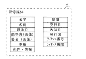
記憶媒体21は、スマートカード2の所持者、つまり車両の運転を公的機関により許可された者について、図2に示すように、名字、名前、誕生日、顔写真の画像、署名の画像、運転が許可された車両の種類、運転の条件・情報及び運転の制限を格納する。さらに、記憶媒体21は、電子運転免許証について、発行日、失効日、発行国、ライセンス番号及びライセンス機関を格納する。なお、公的機関以外が記憶媒体21内の情報を編集できないように、スマートカード2は構成されることが好ましい。
【0018】
再度図1を参照する。スマートカード2において、制御部22は、本体装置3からの要求に従って、記憶媒体21から誕生日をユーザ情報Da の一例として読み出す。
ユーザ情報通信部23は、制御部22により読み出されたユーザ情報Da を本体装置3に送信する。
【0019】
また、本体装置3は、典型的には車両に設置され、ユーザ情報通信部31と、地図格納部32と、パラメータテーブル格納部33と、ロケータ34と、交通情報受信部35と、プログラム格納部36と、制御部37と、出力部の典型例である表示部38及び音声出力部39とを備える。
ユーザ情報通信部31は、上記車両のドライバが所持するスマートカード2から送られてくるユーザ情報Da を受信する。ここで、車両には、ドライバ以外の者が同乗する場合があり、この同乗者もまた、自身のスマートカード2を所持している場合がある。このような状況であっても、ユーザ情報通信部31は、ドライバのスマートカード2のみからユーザ情報Da を受信できるように、車両の座席の内、運転席に最も近接する位置に設置される。このような位置において、ユーザ情報通信部31は、自身の周囲に複数のスマートカード2が存在する場合には、受信信号のレベルが最大のもの、つまり運転席に座るドライバが所持するスマートカード2と無線通信を行って、ユーザ情報Da を受信する。
【0020】
地図格納部32は、少なくとも、内部の記録媒体に書き込まれた情報を読み出し可能な装置であって、図3に示すように、地図データベースDBa 及び文字データベースDBb を格納する。地図データベースDBa は、周知のもので良いため簡単に説明すると、地図画像の描画に必要な複数のオブジェクトを構成するデータセットと、地図画像の描画及び経路探索に必要であって地図上の道路網のつながりを表す道路ネットワークデータとを格納する。
【0021】
また、文字データベースDBb は、地図画像上に重畳可能なテキストの集まりであって、より具体的には、1個以上の第一種情報セットISa と、1個以上の第二種情報セットISb とを含む。各第一種情報セットISa は、地図画像にとって重要度の高いテキスト(図示した例は交差点名及び道路名)及び合成位置を含む。また、各第二種情報セットISb は、地図画像にとって重要度の低いテキスト(図示した例は建造物名及び会社名)及び合成位置を含む。合成位置は、同じ第一種情報セットISa 又は第二種情報セットISb に含まれるテキストを、地図画像上のどこに合成するのかを、例えば緯度及び経度を使って示す。
【0022】
ところで、従来の地図画像には、例えば、交差点名、道路名、建造物名及び会社名に代表される様々なテキストが合成される。しかしながら、過剰なテキストが合成された地図画像は、高齢者には必ずしも親切なものではなく、それよりもむしろ、誘導・案内に必要不可欠なテキストのみが合成された地図画像の方が高齢者から歓迎されると想定できる。それに対して、若年者は、多くのテキストが合成された地図画像を苦にしないと想定できる。テキストの重要度については、上記のような観点から決定される。つまり、交差点名及び道路名は、高齢者及び若年者に関わらず誘導・案内に重要な情報であるため、それらには高い重要度が割り当てられる。それに対し、建造物名及び会社名は、誘導・案内の補助的な役割を果たす場合が多く、交差点名及び道路名と比較すると重要度が低い。そのため、高齢者向けの地図画像に、交差点名及び道路名を合成する必要性が乏しいと想定できる。以上の観点から、建造物名及び会社名には低い重要度が割り当てられる。
【0023】
再度図1を参照する。パラメータテーブル格納部33は、内部の記録媒体に書き込まれた情報を読み出し可能な装置であって、典型的には、地図格納部32を構成するものと同じ装置である。以上のようなパラメータテーブル格納部33には、図4に示すように、車両の誘導・案内に必要なパラメータが記述されたパラメータテーブルTPMが格納される。図4において、パラメータテーブルTPMには、基準年齢Y1 歳未満のドライバに適用される長辺距離La1及び短辺距離Lb1の組み合わせと、音量V1 と、切替え周期F1 と、表示重要度DL1 と、交差点情報の出力距離TP1 とが記述される。さらに、パラメータテーブルTPMには、基準年齢Y1 歳以上のドライバに適用される長辺距離La2及び短辺距離Lb2の組み合わせと、音量V2 と、切替え周期F2 と、表示重要度DL2 と、交差点情報の出力距離TP2 とが記述されている。
【0024】
以上のパラメータテーブルTPMにおいて、基準年齢Y1 は、ドライバが高齢者か否かを特定するための基準値である。
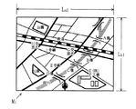
長辺距離La1及び短辺距離Lb1の組み、並びに長辺距離La2及び短辺距離Lb2の組みは共に、本体装置3が作成する地図の範囲を特定する値である。ただし、長辺距離La2は長辺距離La1よりも小さい値に、短辺距離Lb2は短辺距離Lb1よりも小さい値に設定される。例えば、図5に示すように、短辺距離Lb1が400mで、長辺距離La1が480mであると仮定すると、短辺距離Lb2は例示的に320mで、長辺距離La2は例示的に384mと設定される(点線部分参照)。
【0025】
音量V1 及びV2 は共に、音声出力部39から出力される音声の大きさである、ただし、音量V2 は、音量V1 よりも大きな数値に設定される。
切替え周期F1 及びF2 は共に、交通情報受信部35が受信する交通情報Db (詳細は後述)の表示タイミングを示す数値であり、より具体的には、交通情報Db を表示する時間間隔を示す。ただし、切替え周期F2 は、切替え周期F1 よりも大きい数値に設定される。
【0026】
表示重要度DL1 及びDL2 は共に、地図画像に合成されるテキストの重要度を示す。ただし、表示重要度DL1 は、重要度が「高」及び「低」のテキストを合成することを示しており、表示重要度DL2 は、重要度が「高」のみのテキストを合成することを示している。
ところで、後述するように、本体装置3は、車両が現在接近している交差点から所定距離だけ前に到達した時点で、「次の交差点を直進、右折又は左折してください」という内容の音声ガイダンスを出力する。出力距離TP1 及びTP2 は共に、上記の音声ガイダンスが出力される地点を、接近中の交差点から起算した距離を使って示す。ただし、出力距離TP2 は、出力距離TP1 よりも大きい値に設定される。
【0027】
再度図1を参照する。ロケータ34は、外部の測位システム(典型的には、GPS(Global Positioning System ))の受信機、及び/又は自律航法センサ群を含む。GPS受信機は定期的に、上記測位システムからの受信情報を使って、緯度及び経度を使って表現された車両の現在位置を制御部37に出力する。自律航法センサ群は典型的には、速度センサ及び方位センサを含み、速度センサ及び方位センサは定期的に、ユーザの移動速度及び移動方向を検出して、制御部37に出力する。
【0028】
交通情報受信部35は典型的には、VICS(Vehicle Information Communication System)から定期的に送られてくる交通情報Db を受信して、制御部37のRAMに格納する。VICSは、道路網における現在の交通状況を示す様々な交通情報Db を提供しているが、本実施形態では便宜上、図6に示すように、交通情報Db は、交通事故による交通規制が発生する地点を示す交通規制画像RIを含むと仮定する。
【0029】
プログラム格納部36は典型的には、ROM(Read Only Memory)から構成され、本体装置3が行う誘導・案内の処理手順を記述したコンピュータプログラム(以下、単にプログラムと称する)361を格納する。
制御部37は典型的には、CPU(Central Processing Unit)及びRAM(Random Access Memory)から構成され、プログラム361に従って、誘導・案内に必要な処理を行う。
表示部38は、制御部37により作成される各種画像を表示する。音声出力部39は、制御部37により設定された音量V1 又はV2 で制御部37により作成される各種合成音声を出力する。
【0030】
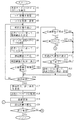
次に、図7及び図8に示すフローチャートを参照して、上述のナビゲーションシステム1が実行する車両の誘導・案内について説明する。まず、ドライバが車両の運転席に着き、さらにナビゲーションシステム1の電源が投入される。これにより、制御部37は、プログラム格納部36内のプログラム361の実行を開始する。その後、制御部37の制御下で、本体装置3のユーザ情報通信部31は、信号受信レベルが最大のスマートカード2を特定し、特定したスマートカード2側のユーザ情報通信部23とコネクションを確立する(ステップA1)。
【0031】
次に、制御部37は、ユーザ情報Da の一例としての誕生日をスマートカード2に要求するための情報(以下、送信要求と称する)を生成し、ユーザ情報通信部31を通じてスマートカード2に送信する。スマートカード2において、制御部22は、ユーザ情報通信部23を通じて送信要求を受信し、これに応答して、記憶媒体21からユーザ情報Da を読み出し、ユーザ情報通信部23を通じて本体装置3に送信する。本体装置3において、制御部37は、ユーザ情報通信部31を通じてユーザ情報Da を受信する(ステップA2)。
【0032】
次に、制御部37は、ステップA3において、受信したユーザ情報Da から、ドライバの年齢を算出した後、算出した年齢が基準年齢Y1 以上か否かを判断する。基準年齢Y1 以上でないと判断した場合、制御部37は、パラメータテーブルTPMから、長辺距離La1及び短辺距離Lb1の組み、音量V1 、切替え周期F1 、表示重要度DL1 及び交差点情報の出力距離TP1 を取り出す。その後、制御部37は、長辺距離La1及び短辺距離Lb1の組み、切替え周期F1 、表示重要度DL1 及び交差点情報の出力距離TP1 を、内部のRAMにおいて予約された記憶領域に設定し、さらに、音量V1 を音声出力部39に出力する。
【0033】
また、算出年齢が基準年齢Y1 以上であると判断した場合、制御部37は、ステップA3において、パラメータテーブルTPMから、長辺距離La2及び短辺距離Lb2の組み、音量V2 、切替え周期F2 、表示重要度DL2 及び交差点情報の出力距離TP2 を取り出す。その後、制御部37は、長辺距離La2及び短辺距離Lb2の組み、切替え周期F2 、表示重要度DL2 及び交差点情報の出力距離TP2 を、RAMの予約記憶領域に設定する。さらに、制御部37は、取り出した音量V2 を音声出力部39に出力する(ステップA3)。
【0034】
次に、制御部37は、ロケータ34から得られる車両の現在位置を取得し、さらに、車両の移動速度及び移動方向を使って、取得した車両の現在位置を補正して、車両の正確な現在位置を導出する(ステップA4)。
次に、制御部37は、ステップA4で導出した車両の現在位置と、ステップA3で設定された長辺距離La1及び短辺距離Lb1の組み並びに長辺距離La2及び短辺距離Lb2の組みのいずれか(図5参照)とから、今回描画すべき地図画像の特徴点の座標値を導出する(ステップA5)。ここで、特徴点とは、長方形形状の地図画像の4頂点である。また、このような地図画像において、車両の現在位置が重畳される位置は予め決められているため、各特徴点の座標値は容易に算出可能である。ここで、以下の説明では、現在位置、長辺距離La1及び短辺距離Lb1から導出された4頂点で規定される矩形範囲を、描画範囲RA1 と称し、現在位置、長辺距離La2及び短辺距離Lb2から導出された4頂点で規定される矩形範囲を、描画範囲RA2 と称する。
【0035】
次に、制御部37は、ステップA5で導出した描画範囲RA1 又はRA2 の地図画像の作成に必要な全オブジェクトと道路ネットワークデータとを、地図格納部32の地図データベースDBa から取得する(ステップA6)。
次に、制御部37は、ステップA3で設定された表示重要度DL1 又はDL2 に従って、地図画像の作成に必要なテキストを、地図格納部32の文字データベースDBb から取得する(ステップA7)。具体的には、ステップA3でドライバの年齢が基準年齢Y1 未満であると判断された場合には、第一種情報セットISa 及び第二種文字セットISb が取り出される。また、逆の場合には、第一種情報セットISa のみが取り出される。
【0036】
次に、制御部37は、ステップA6で取得したオブジェクト及び道路ネットワークデータと、ステップA7で取り出した第一種情報セットISa 及び第二種文字セットISb 又は第一種情報セットISa のみとを使って、予め定められたピクセルサイズを有する地図画像M1 及びM2 のいずれかを作成する(ステップA8)。より具体的には、ドライバが基準年齢Y1 未満と判断された場合、制御部37は、相対的に広い描画範囲RA1 に含まれる全オブジェクト及び道路ネットワークデータを使って画像を描画し、第一種情報セットISa 及び第二種文字セットISb に含まれるテキストを所定の合成位置に重畳し、さらに、車両を示すマークをステップA4で導出した現在位置に重畳し、これによって、図9に示すような地図画像M1 を作成する。また、ドライバが基準年齢Y1 以上と判断された場合、制御部37は、相対的に狭い描画範囲RA2 に含まれる全オブジェクト及び道路ネットワークデータを使って画像を描画し、第一種情報セットISa に含まれるテキストを所定の合成位置に重畳し、さらに、車両を示すマークをステップA4で導出した現在位置に重畳して、図10に示すような地図画像M2 を作成する。
【0037】
ここで、描画範囲RA2 は描画範囲RA1 より狭いが、地図画像M1 及びM2 は互いに同じピクセルサイズを有する。従って、地図画像M2 には、相対的に狭い範囲の様子が拡大して表現されていることになる。また、地図画像M2 には、相対的に重要と想定される交差点名及び道路名のみが重畳される。これによって、高齢者にとって親切な地図画像M2 を提供することが可能となる。
【0038】
再度図7を参照する。ステップA8の次に、制御部37は、作成した地図画像M1 又はM2 を表示部38に転送し、表示部38は、受け取った地図画像M1 又はM2 を表示する(ステップA9)。
【0039】
ところで、上述したように、交通情報受信部35は典型的には、VICSからの交通情報Db を受信した場合、受信したものを制御部37に格納する。ステップA9の次に、制御部37は、新しい交通情報Db が格納されているか否かを判断する(ステップA10)。新規格納されている場合、制御部37は、今回の交通情報Db が前回のものと比較して変化しているか否かを判断する(ステップA11)。変化している場合、本実施形態では、新たな交通規制が発生していることになるので、制御部37は、今回の交通情報Db から、図6に示すように、現在発生している交通規制を表す交通規制画像RIを作成して、表示部38に転送する。表示部38は、受信した交通規制画像RIを表示する(ステップA12)。
【0040】
ステップA12によって、表示部38の表示画面は、現在表示されている地図画像M1 又はM2 から、図6に示すような交通規制画像RIに切り替わる。ここで、制御部37は、表示終了タイミングが来るまで(ステップA13)、ステップA12で作成した交通規制画像RIを表示部38に転送し続ける。また、表示終了タイミングが来ると、制御部37は、図示しないタイマから得られる現在時刻を、交通規制画像RIの表示が終了した時刻(以下、表示終了時刻と称する)として取得する。さらに、制御部37は、制御部37は、取得した表示終了時刻に、ステップA3で設定された切替え周期F1 又はF2 を加算して、次に交通規制画像RIを表示すべき時刻(以下、次表示時刻と称する)Tnxを導出し記憶する(ステップA14)。なお、次表示時刻Tnxは、後述するステップA15で表示タイミングを導出するために使われる。
【0041】
また、ステップA11で、新たに格納された交通情報Db が変化していないと判断した場合、交通規制画像RIの表示タイミングか否かを判断する(ステップA15)。より具体的には、ステップA15では、現在記憶している次表示時刻Tnxを現在時刻が過ぎているか否かが判断される。次表示時刻Tnxを現在時刻が過ぎている場合、制御部37は、ステップA12を行う。
【0042】
以上の処理によって、無変化の交通情報Db に関し、交通規制画像RIは、切替え周期F1 又はF2 を使って算出される次表示時刻Tnxに従って出力されることになる。ここで、切替え周期F2 は切替え周期F1 よりも大きい値に設定される。これによって、高齢者が車両を運転している場合には、地図画像M2 から交通規制画像RIへと切り替わる回数を相対的に減らして、高齢者に親切な車両の誘導・案内を実現することが可能になる。
【0043】
また、ステップA10で新しい交通情報Db が格納されていないと判断された場合、ステップA14の実行後又はステップA15で交通情報RIの表示タイミングではないと判断された場合に、制御部37は、周知の手法により、経路探索を行うか否かを判断し(ステップA16)、経路探索を行わないと判断した場合、制御部37は、ステップA4に戻る。
【0044】
逆に、経路探索を行うと判断した場合、制御部37は、経路探索に必要となる開始地点及び終了地点を、周知の手法で取得し(ステップA17)、その後、地図格納部32に格納されている地図データベースDBa から、経路探索に必要な道路ネットワークデータを取得する(ステップA18)。その後、制御部37は、取得した道路ネットワークデータを使って、ステップA17で設定された開始地点から終了地点まで、最短時間又は最小距離で車両が移動可能な経路を探索する(ステップA19)。
【0045】
次に、制御部37は、ステップA4と同様にして、車両の現在位置を導出し(ステップA20)、その後、ステップA17で取得した終了地点に、ステップA20で導出した現在位置が一致するか否かを判断する(ステップA21)。両者が一致した場合、本体装置3は終了地点まで車両を誘導・案内したことになるので、図7及び図8の処理を終了する。
【0046】
逆に、ステップA21で現在位置が終了地点と一致しないと判断した場合、制御部37は、ステップA5と同様の手法で、ステップA20で導出した現在位置を使って描画範囲RA1 又はRA2 を導出する(図8;ステップA22)。その後、制御部37は、ステップA6と同様に、導出した描画範囲RA1 又はRA2 の地図画像の作成に必要な全オブジェクトを、地図格納部32から取得する(ステップA23)。なお、道路ネットワークデータに関しては、ステップA18で取得されているので、ステップA22で地図格納部32から読み出さなくとも良い。さらに、制御部37は、ステップA7と同様に、設定された表示重要度DL1 又はDL2 に従って、地図画像の作成に必要なテキストを、地図格納部32から取得する(ステップA24)。
【0047】
次に、制御部37は、地図画像M1 及びM2 と同じピクセルサイズの地図画像M3 及びM4 のいずれかを作成する(ステップA25)。より具体的には、ドライバが基準年齢Y1 未満と判断されている場合、制御部37は、地図画像M1 と同様の画像に、ステップA19で導出した経路の内、描画範囲RA1 に含まれる部分を重畳して、図11に示すような地図画像M3 を作成する。また、ドライバが基準年齢Y1 以上と判断されている場合、制御部37は、地図画像M2 と同様の画像に、ステップA19で導出した経路の内、描画範囲RA2 に含まれる部分を重畳して、図12に示すような地図画像M4 を作成する。
次に、制御部37は、作成した地図画像M3 又はM4 を表示部38に転送し、表示部38は、受け取った地図画像M1 又はM2 を表示する(ステップA26)。ここで、描画範囲RA2 は描画範囲RA1 より狭いが、地図画像M3 及びM4 は互いに同じピクセルサイズを有する。従って、地図画像M4 には、相対的に狭い範囲の様子が拡大して表現されていることになる。また、地図画像M4 には、相対的に重要と想定される交差点名及び道路名のみが重畳される。これによって、高齢者にとって親切な地図画像M4 を提供することが可能となる。
【0048】
次に、制御部37は、ステップA19で得られた経路を使って、ステップA20で導出した現在位置から、車両が次に通過する交差点までの距離D3 を算出し(ステップA27)、その後、音声ガイダンスを行うか否かを判断する(ステップA28)。具体的には、ステップA27で得られた距離D3 がステップA3で設定された出力距離TP1 又はTP2 以下であれば、制御部37は、車両が交差点に接近中であると判断して、前述したように、「次の交差点を直進、右折又は左折してください」という内容の合成音声を作成し、音声出力部39に転送する。音声出力部39は、ステップA3で制御部37に設定された音量V1 又はV2 で、受け取った合成音声が表す内容を出力する(ステップA29)。
【0049】
以上から明らかなように、高齢者が車両を運転している場合には、音声出力部39からの音量は相対的に大きくし、さらに、音声ガイダンスを相対的に交差点から離れた位置で出力する。これによって、高齢者に親切な車両の誘導・案内を実現することが可能になる。
【0050】
ステップA28で距離D3 が出力距離TP1 又はTP2 以下でない場合、若しくはステップA29の次に、制御部37は、ステップA10と同様に、新しい交通情報Db が格納されているか否かを判断し(ステップA30)、更新されていれば、ステップA11と同様に、今回の交通情報Db が前回のものと比較して変化しているか否かを判断する(ステップA31)。
【0051】
交通情報Db が変化している場合、制御部37は、ステップA12と同様に、交通規制画像RIを作成して、表示部38に表示させる(ステップA32)。これによって、表示部38の表示画面は、現在表示されている地図画像M3 又はM4 から、交通規制画像RIに切り替わる。ここで、制御部37は、所定の表示終了タイミングが来るまで(ステップA33)、ステップA32で作成した交通規制画像RIを表示部38に表示させ続ける。また、表示終了タイミングが来ると、制御部37は、ステップA14と同様にして、後述のステップA35で必要になる次表示時刻Tnxを導出し記憶する(ステップA34)。
【0052】
また、ステップA31で、新たに格納された交通情報Db が変化していないと判断した場合、制御部37は、ステップA15と同様に、交通規制画像RIの表示タイミングか否かを判断し(ステップA35)、表示タイミングであれば、ステップA32を行う。
【0053】
以上の処理によって、無変化の交通情報Db は、切替え周期F1 又はF2 を使って算出される次表示時刻Tnxに従って出力されることになる。ここで、切替え周期F2 は切替え周期F1 よりも大きい値に設定される。これによって、高齢者が車両を運転している場合には、地図画像M4 から交通規制画像RIへと切り替わる回数を相対的に減らして、高齢者に親切な車両の誘導・案内を実現することが可能になる。
【0054】
また、ステップA31で新しい交通情報Db が格納されていないと判断された場合、ステップA34を実行後、又はステップA35で交通情報RIの表示タイミングではないと判断された場合、制御部37は、ステップA20に戻る。
【0055】
なお、上述では、好ましい実施形態として、記憶媒体21はスマートカード2に備わるとして説明したが、これに限らず、SDカード(登録商標)に代表される可搬性メディアそのものであっても構わない。これら可搬性メディアは、本体装置3と無線通信を行えないので、本体装置3は、ユーザ情報通信部31の代わりに、可搬性メディアから情報を読み出すためのリーダを備える必要がある。
【0056】
また、上述では、好ましい実施形態として、車載型の本体装置3について説明したが、これに限らず、本体装置3は、例えば、パーソナルコンピュータ、携帯電話、PDA(Personal Digital Assistant)のように携帯可能な構成であっても構わない。
【0057】
また、上述では、好ましい実施形態として、本体装置3に備わるユーザ情報通信部31は、運転席に最も近接する位置に設置された状態で、受信信号のレベルが最大のスマートカード2と無線通信を行っていた。しかし、これに限らず、下記の方法で、無線通信すべきスマートカード2を特定しても構わない。つまり、本体装置3には、記憶媒体21に格納されている情報であって、車両のドライバとなりえる者を特定するもの(典型的には名字及び名前の組み合わせ)が登録される。本体装置3は、周辺のスマートカード2それぞれと無線通信を行って、それぞれから所持者の名字及び名前の組み合わせを取得する。本体装置3は、予め登録されている名字及び名前と一致するものを送信してきたスマートカード2と無線通信を行う。
【0058】
また、上述では、本体装置3は、ユーザ情報Da の一例としての誕生日から、ドライバの年齢を導出して、車両の誘導・案内に必要な各種情報の出力を制御していた。しかし、これに限らず、ユーザ情報Da としての電子運転免許証の発行日からドライバの運転歴を導出し、導出した運転歴を使って、本体装置3は、車両の誘導・案内に必要な各種情報の出力を制御しても構わない。
【0059】
また、上述では、例示的に、基準年齢Y1 以上か否かに基づいて、車両の誘導・案内に必要な各種情報の出力を制御していた。しかし、これに限らず、基準年齢を2個以上に増やしても構わない。
【0060】
また、上述では、ステップA12又はA32において、交通規制画像RIを表示していた。しかし、交通情報Db には他にも様々な情報が含まれるので、ステップA12又はA32では、交通情報Db に含まれるものであれば、どの情報から作成された画像が表示されても良い。
【0061】
また、上述では、例示的に、長辺距離及び短辺距離の組み、音量、切替え周期、表示重要度並びに交差点情報の出力距離がパラメータテーブル格納部33に記述されていた。しかし、これらに限らず、パラメータテーブルTPMに記述されるのは、車両の誘導・案内に必要な各種情報の出力を制御するためのパラメータであれば何でも構わない。他のパラメータとしては、例えば、表示部38から出力される画像の色調及び輝度がある。
【0062】
また、上述では例示的に、地図格納部32は、地図画像上に重畳可能なテキストの集まりである文字データベースDBb を格納していた。しかし、これに限らず、地図格納部32は、地図画像上に重畳可能なランドマーク画像及び/又はシンボルマークのためのデータベースを格納していても構わない。また、各ランドマーク画像又はシンボルマークは、テキストと同様に、重要度に従って分類される。制御部37は、テキストの場合と同様、必要なランドマーク画像及び/又はシンボルマークを取得して、取得したものを使って地図画像を作成する。
【0063】
また、上述では、制御部37は、二次元の地図画像M1 〜M4 を作成していたが、これに限らず、三次元の地図画像を作成しても構わない。
【図面の簡単な説明】
【図1】本発明の一実施形態に係るナビゲーションシステム1の構成を示すブロック図である。
【図2】図1に示す記憶媒体21に格納される情報を示す模式図である。
【図3】図1に示す地図格納部32に格納されるデータを示す模式図である。
【図4】図1に示すパラメータテーブル格納部33に格納されるパラメータを示す模式図である。
【図5】図4に示す長辺距離及び短辺距離の組みを説明するための模式図である。
【図6】図1の交通情報受信部35が受信する交通情報Db に含まれる交通規制画像RIを示す模式図である。
【図7】図1のナビゲーションシステム1による車両の誘導・案内の手順を示すフローチャートの前半部分である。
【図8】図1のナビゲーションシステム1による車両の誘導・案内の手順を示すフローチャートの後半部分である。
【図9】図7のステップA8で作成される地図画像M1 の一例を示す模式図である。
【図10】図7のステップA8で作成される地図画像M2 の一例を示す模式図である。
【図11】図8のステップA25で作成される地図画像M3 の一例を示す模式図である。
【図12】図8のステップA25で作成される地図画像M4 の一例を示す模式図である。
【符号の説明】
1…ナビゲーションシステム
2…スマートカード
21…記憶媒体
22…制御部
23…ユーザ情報通信部
3…本体装置
31…ユーザ情報通信部
32…地図格納部
33…パラメータテーブル格納部
34…ロケータ
35…交通情報受信部
36…プログラム格納部
361…コンピュータプログラム
37…制御部
38…表示部
39…音声出力部[0001]
BACKGROUND OF THE INVENTION
The present invention relates to a navigation system, and more particularly to a navigation system that can use user information read from a storage medium.
[0002]
[Prior art]
Some navigation systems are disclosed in JP-A-6-76003. This navigation system is mounted on a vehicle and performs the following processing. The navigation system continuously checks the driver's driving skill level while driving the vehicle. In addition, while driving the vehicle, the navigation system sets the current position on the map and the user's destination, and then predicts the road conditions within the range defined based on the set current position and destination. Thereafter, the navigation system determines an optimum route in consideration of the current road condition, and displays a map in which the decided optimum route is synthesized. The driver drives the vehicle according to the determined optimum route, but if the driver wants to travel on another route for reasons represented by traffic congestion, the driver instructs the navigation system to that effect. In response to this instruction, the navigation system determines another route based on the driving skill level of the driver and the current road conditions, and guides the driver according to the determined route. Through the above processing, the navigation system guides the driver to the destination according to the optimum route determined with reference to the driving skill level.
[0003]
[Patent Document 1]
JP-A-6-76003
[0004]
[Problems to be solved by the invention]
However, the conventional navigation system has a problem that only the same guidance and guidance can be performed for all drivers. For example, since the output timing of intersection information is fixed during driver guidance / guidance, the conventional navigation system may not be able to provide sufficient time for the elderly to enter the intersection. Further, since the format of the display map is fixed, the conventional navigation system may give excessive information that cannot be processed by the elderly.
[0005]
Therefore, an object of the present invention is to provide a navigation system that can perform different guidance and guidance depending on a driver.
[0006]
[Means for Solving the Problems and Effects of the Invention]
In order to achieve the above object, a first aspect of the present invention is a navigation system, a storage medium storing user information,vehicleParameter storage for storing at least one parameter required for output control of information required for guidance and guidance of the user, and parameter acquisition for acquiring the necessary parameter from the parameter storage based on user information stored in the storage medium And the parameters acquired by the parameter acquisition unit,vehicleAn information generator that generates information necessary for guidance and guidance, and informationGenerationIn the departmentGenerationAn output unit for outputting the recorded informationThe storage medium is included in the smart card, the parameter storage unit, the parameter acquisition unit, the information generation unit, and the output unit are included in the main unit, and the smart card is a driving license for the vehicle, and the age of the owner or electronic driving The issuance date of the license is stored as user information in the storage medium, and the parameter storage unit stores one or more parameters for each predetermined age range or driving history range. The acquisition unit acquires necessary parameters from the parameter storage unit based on the driving history that can be calculated from the age stored in the storage medium or the date of issue stored in the storage medium, and the current traffic situation in the road network is obtained. A traffic information receiving unit that receives the traffic information shown, and the parameter storage unit has a switching cycle indicating a display timing of the traffic information received by the traffic information receiving unit. It is stored for each predetermined age range or driving history range, and the parameter acquisition unit is based on the age stored in the storage medium or the driving history that can be calculated from the issue date stored in the storage medium The information generation unit includes a display timing determination unit that determines whether or not the current display timing is based on the switching cycle acquired by the parameter acquisition unit, and outputs an output unit. Displays the traffic information received by the traffic information receiving unit as information when the display timing determining unit determines that it is the display timing.The
According to the first aspect of the present invention, parameters necessary for output control of information necessary for guidance and guidance of an object are stored for each predetermined age range or driving history range. Of these parameter groups classified for each range, the switching cycle indicating the display timing of traffic information is acquired based on the age stored in the smart card or the driving history that can be calculated from the date of issue stored in the smart card. Is done. Traffic information for guiding and guiding the object is displayed according to the acquired switching cycle. This makes it possible to realize a navigation system that can update traffic information at an appropriate timing according to the driver..
[0015]
First of the present invention2Is a method of performing navigation using parameters necessary for output control of user information and information necessary for vehicle guidance / guidance, and the age of the owner stored in the smart card or the electronic driving license A user information acquisition step for acquiring a certificate issuance date, a traffic information reception step for receiving traffic information indicating current traffic conditions in the road network, and the age of the holder or the electronic license acquired by the user information acquisition step. Based on the driving history that can be calculated from the date of issue, a parameter acquisition step that acquires a switching cycle indicating the display timing of the necessary traffic information, and whether or not the present is the display timing based on the switching cycle acquired by the parameter acquisition step Display timing determining step for determining whether or not the display timing is determined in the display timing determining step. If it is determined that, as information, and an output step of displaying the traffic information received by the traffic information receiving step.
First of the present invention3The aspect of the second2In this aspect, the navigation method is realized by a computer program.
First of the present invention4The aspect of the second3In this aspect, the computer program is recorded on a storage medium.
[0016]
DETAILED DESCRIPTION OF THE INVENTION
FIG. 1 is a block diagram showing a configuration of a
[0017]
The
As shown in FIG. 2, the
[0018]
Refer to FIG. 1 again. In the
The user
[0019]
The
The user
[0020]
The
[0021]
In addition, character database DBbIs a collection of text that can be superimposed on a map image, more specifically, one or more first-type information sets IS.aAnd one or more second type information set ISbIncluding. Each
[0022]
By the way, for example, various texts represented by an intersection name, a road name, a building name, and a company name are combined with a conventional map image. However, a map image with an excessive amount of text is not necessarily friendly to the elderly. Rather, a map image with only the text essential for guidance and guidance is better for elderly people. It can be assumed that it will be welcomed. On the other hand, young people can assume that they do not suffer from a map image in which many texts are synthesized. The importance of the text is determined from the above viewpoint. That is, since the intersection name and the road name are important information for guidance / guidance regardless of elderly people and young people, high importance is assigned to them. On the other hand, the building name and the company name often play an auxiliary role of guidance / guidance and are less important than the intersection name and road name. Therefore, it can be assumed that the necessity of synthesizing the intersection name and the road name on the map image for the elderly is scarce. From the above viewpoint, a low importance is assigned to the building name and the company name.
[0023]
Refer to FIG. 1 again. The parameter
[0024]
The above parameter table TPMIn reference age Y1Is a reference value for specifying whether or not the driver is an elderly person.
Long side distance La1And short side distance Lb1And long side distance La2And short side distance Lb2Are the values that specify the range of the map created by the
[0025]
Volume V1And V2Are the magnitudes of the voices output from the
Switching cycle F1And F2Both the traffic information D received by the traffic
[0026]
Display importance DL1And DL2Both indicate the importance of the text combined with the map image. However, display importance DL1Indicates that texts of importance “high” and “low” are synthesized, and the display importance DL2Indicates that texts with a high importance level are synthesized.
By the way, as will be described later, when the
[0027]
Refer to FIG. 1 again. The
[0028]
The traffic
[0029]
The
The
The
[0030]
Next, vehicle guidance / guidance performed by the above-described
[0031]
Next, the
[0032]
Next, the
[0033]
The calculated age is the reference age Y1When determining that the above is true, the
[0034]
Next, the
Next, the
[0035]
Next, the
Next, the
[0036]
Next, the
[0037]
Here, the drawing range RA2Is the drawing range RA1Narrower but map image M1And M2Have the same pixel size. Therefore, the map image M2In this, a state in a relatively narrow range is expressed in an enlarged manner. Map image M2Only the intersection name and the road name that are assumed to be relatively important are superimposed on. This makes the map image M kind to the elderly2Can be provided.
[0038]
Refer to FIG. 7 again. After step A8, the
[0039]
Incidentally, as described above, the traffic
[0040]
By step A12, the display screen of the
[0041]
In step A11, the traffic information D newly stored is stored.bIs determined not to change, it is determined whether or not it is the display timing of the traffic regulation image RI (step A15). More specifically, in step A15, the currently stored next display time TnxIt is determined whether or not the current time has passed. Next display time TnxIf the current time has passed, the
[0042]
Through the above processing, unchanged traffic information DbIn relation to the traffic regulation image RI, the switching cycle F1Or F2Next display time T calculated usingnxWill be output according to. Here, the switching cycle F2Is the switching cycle F1Is set to a larger value. Thus, when an elderly person is driving a vehicle, the map image M2It is possible to relatively reduce the number of times of switching from to the traffic regulation image RI and to realize guidance and guidance of vehicles that are kind to the elderly.
[0043]
In step A10, new traffic information DbIf the
[0044]
On the other hand, when it is determined that the route search is to be performed, the
[0045]
Next, the
[0046]
Conversely, if it is determined in step A21 that the current position does not coincide with the end point, the
[0047]
Next, the
Next, the
[0048]
Next, the
[0049]
As is clear from the above, when an elderly person is driving the vehicle, the volume from the
[0050]
Distance A in step A28ThreeIs the output distance TP1Or TP2If not, or after step A29, the
[0051]
Traffic information DbIs changed, the
[0052]
In step A31, the newly stored traffic information DbWhen it is determined that is not changed, the
[0053]
Through the above processing, unchanged traffic information DbIs the switching cycle F1Or F2Next display time T calculated usingnxWill be output according to. Here, the switching cycle F2Is the switching cycle F1Is set to a larger value. Thus, when an elderly person is driving a vehicle, the map image MFourIt is possible to relatively reduce the number of times of switching from to the traffic regulation image RI and to realize guidance and guidance of vehicles that are kind to the elderly.
[0054]
In step A31, new traffic information DbIs determined not to be stored, after executing step A34, or when it is determined in step A35 that the display timing of the traffic information RI is not reached, the
[0055]
In the above description, the
[0056]
In the above description, the vehicle-mounted
[0057]
In the above description, as a preferred embodiment, the user
[0058]
Further, in the above description, the
[0059]
In the above description, for example, the reference age Y1Based on whether or not this is the case, the output of various information necessary for vehicle guidance and guidance has been controlled. However, the present invention is not limited to this, and the reference age may be increased to two or more.
[0060]
In the above description, the traffic regulation image RI is displayed in step A12 or A32. However, traffic information DbSince various other information is included in step A12 or A32, traffic information DbAs long as it is included in the image, an image created from any information may be displayed.
[0061]
In the above description, the long distance and short distance combinations, volume, switching period, display importance, and intersection information output distance are described in the parameter
[0062]
Further, in the above description, for example, the
[0063]
Moreover, in the above-mentioned, the
[Brief description of the drawings]
FIG. 1 is a block diagram showing a configuration of a
FIG. 2 is a schematic diagram showing information stored in the
FIG. 3 is a schematic diagram showing data stored in the
4 is a schematic diagram showing parameters stored in a parameter
5 is a schematic diagram for explaining a combination of a long side distance and a short side distance shown in FIG. 4. FIG.
6 is traffic information D received by the traffic
7 is a first half of a flowchart showing a procedure for guiding and guiding a vehicle by the
FIG. 8 is a latter half of a flowchart showing a procedure of vehicle guidance / guidance by the
9 is a map image M created in step A8 in FIG. 7;1It is a schematic diagram which shows an example.
10 is a map image M created in step A8 in FIG. 7;2It is a schematic diagram which shows an example.
11 is a map image M created in step A25 of FIG.ThreeIt is a schematic diagram which shows an example.
12 is a map image M created in step A25 of FIG.FourIt is a schematic diagram which shows an example.
[Explanation of symbols]
1. Navigation system
2. Smart card
21 ... Storage medium
22 ... Control unit
23. User information communication unit
3 ... Main unit
31 ... User information communication unit
32 ... Map storage
33 ... Parameter table storage unit
34 ... Locator
35 ... Traffic information receiver
36 ... Program storage unit
361 ... Computer program
37 ... Control unit
38 ... Display section
39. Audio output unit
Claims (4)
ユーザ情報を格納する記憶媒体と、
車両の誘導・案内に必要な情報の出力制御に必要なパラメータを少なくとも1個格納するパラメータ格納部と、
前記記憶媒体に格納されたユーザ情報に基づいて、前記パラメータ格納部から必要なパラメータを取得するパラメータ取得部と、
前記パラメータ取得部が取得したパラメータに従って、前記車両の誘導・案内に必要な情報を生成する情報生成部と、
前記情報生成部で生成された情報を出力する出力部とを備え、
前記記憶媒体はスマートカードに含まれ、前記パラメータ格納部、前記パラメータ取得部、前記情報生成部及び前記出力部は本体装置に含まれ、
前記スマートカードは前記車両の運転免許証であって、所持者の年齢又は電子運転免許証の発行日をユーザ情報として、前記記憶媒体に格納しており、
前記パラメータ格納部は、予め定められた年齢の範囲又は運転歴の範囲毎に、1個以上のパラメータを格納しており、
前記パラメータ取得部は、前記記憶媒体に格納された年齢、または前記記憶媒体に格納された発行日から算出可能な運転歴に基づいて、前記パラメータ格納部から必要なパラメータを取得し、
道路網における現在の交通状況を示す交通情報を受信する交通情報受信部をさらに備え、
前記パラメータ格納部は、前記交通情報受信部により受信された交通情報の表示タイミングを示す切替え周期を、予め定められた年齢の範囲又は運転歴の範囲毎に格納しており、
前記パラメータ取得部は、前記記憶媒体に格納された年齢、又は前記記憶媒体に格納された発行日から算出可能な運転歴に基づいて、前記パラメータ格納部から必要な切替え周期を取得し、
前記情報生成部は、前記パラメータ取得部により取得された切替え周期に基づいて、現在が表示タイミングか否かを判断する表示タイミング判断部を含み、
前記出力部は、前記表示タイミング判断部が表示タイミングであると判断した場合に、情報として、前記交通情報受信部により受信された交通情報を表示する、ナビゲーションシステム。A navigation system,
A storage medium for storing user information;
A parameter storage unit for storing at least one parameter necessary for output control of information necessary for guidance and guidance of the vehicle;
A parameter acquisition unit for acquiring necessary parameters from the parameter storage unit based on user information stored in the storage medium;
According to the parameters acquired by the parameter acquisition unit, an information generation unit that generates information necessary for guidance and guidance of the vehicle;
An output unit that outputs the information generated by the information generation unit,
The storage medium is included in a smart card, and the parameter storage unit, the parameter acquisition unit, the information generation unit, and the output unit are included in a main device,
The smart card is a driving license of the vehicle, and the user's age or the date of issue of the electronic driving license is stored as user information in the storage medium,
The parameter storage unit stores one or more parameters for each predetermined age range or driving history range,
The parameter acquisition unit acquires necessary parameters from the parameter storage unit based on the driving history that can be calculated from the age stored in the storage medium or the date of issue stored in the storage medium,
A traffic information receiving unit for receiving traffic information indicating current traffic conditions in the road network;
The parameter storage unit stores a switching cycle indicating a display timing of traffic information received by the traffic information receiving unit for each predetermined age range or driving history range,
The parameter acquisition unit acquires a necessary switching cycle from the parameter storage unit based on an operation history that can be calculated from the age stored in the storage medium or the issue date stored in the storage medium,
The information generation unit includes a display timing determination unit that determines whether the present is a display timing based on the switching period acquired by the parameter acquisition unit,
The said output part is a navigation system which displays the traffic information received by the said traffic information receiving part as information, when the said display timing judgment part judges that it is a display timing.
スマートカードに格納されている所持者の年齢又は電子運転免許証の発行日を取得するユーザ情報取得ステップと、
道路網における現在の交通状況を示す交通情報を受信する交通情報受信ステップと、
前記ユーザ情報取得ステップにより取得された前記所持者の年齢又は前記電子免許証の発行日から算出可能な運転歴に基づいて、必要な前記交通情報の表示タイミングを示す切り換え周期を取得するパラメータ取得ステップと、
前記パラメータ取得ステップにより取得された切り換え周期に基づいて、現在が表示タイミングか否かを判断する表示タイミング判断ステップと、
前記表示タイミング判断ステップにおいて表示タイミングであると判断した場合に、情報として、前記交通情報受信ステップで受信された交通情報を表示する出力ステップとを備える、ナビゲーション方法。A method for performing navigation using parameters necessary for output control of user information and information necessary for vehicle guidance / guidance,
A user information acquisition step of acquiring the age of the holder stored in the smart card or the date of issue of the electronic driver's license;
A traffic information receiving step for receiving traffic information indicating current traffic conditions in the road network;
A parameter acquisition step for acquiring a switching cycle indicating the necessary display timing of the traffic information based on the driving history that can be calculated from the age of the owner acquired by the user information acquisition step or the date of issue of the electronic license. When,
A display timing determination step for determining whether or not the current display timing is based on the switching period acquired by the parameter acquisition step;
A navigation method comprising: an output step of displaying the traffic information received in the traffic information reception step as information when it is determined that the display timing is in the display timing determination step.
Priority Applications (1)
| Application Number | Priority Date | Filing Date | Title |
|---|---|---|---|
| JP2003088484A JP4039968B2 (en) | 2002-04-03 | 2003-03-27 | Navigation system |
Applications Claiming Priority (2)
| Application Number | Priority Date | Filing Date | Title |
|---|---|---|---|
| JP2002100964 | 2002-04-03 | ||
| JP2003088484A JP4039968B2 (en) | 2002-04-03 | 2003-03-27 | Navigation system |
Publications (3)
| Publication Number | Publication Date |
|---|---|
| JP2004004016A JP2004004016A (en) | 2004-01-08 |
| JP2004004016A5 JP2004004016A5 (en) | 2005-06-23 |
| JP4039968B2 true JP4039968B2 (en) | 2008-01-30 |
Family
ID=30446590
Family Applications (1)
| Application Number | Title | Priority Date | Filing Date |
|---|---|---|---|
| JP2003088484A Expired - Fee Related JP4039968B2 (en) | 2002-04-03 | 2003-03-27 | Navigation system |
Country Status (1)
| Country | Link |
|---|---|
| JP (1) | JP4039968B2 (en) |
Families Citing this family (10)
| Publication number | Priority date | Publication date | Assignee | Title |
|---|---|---|---|---|
| JP2005331282A (en) * | 2004-05-18 | 2005-12-02 | Toyota Motor Corp | Device for providing information |
| JP4770521B2 (en) * | 2006-03-06 | 2011-09-14 | 株式会社デンソー | Landmark presentation device, in-vehicle navigation device, and in-vehicle navigation system |
| JP4843407B2 (en) * | 2006-08-11 | 2011-12-21 | クラリオン株式会社 | Map display device, information center and direction signboard display system |
| JP2009012498A (en) * | 2007-06-29 | 2009-01-22 | Mitsubishi Motors Corp | Inter-vehicle distance control device |
| JP2009187191A (en) * | 2008-02-05 | 2009-08-20 | Denso Corp | Onboard equipment and narrow-band wireless communication system |
| JP5362526B2 (en) * | 2009-11-26 | 2013-12-11 | 株式会社京三製作所 | Map generating apparatus and map generating method |
| JP2011180078A (en) * | 2010-03-03 | 2011-09-15 | Clarion Co Ltd | Navigation system |
| JP2014020783A (en) * | 2012-07-12 | 2014-02-03 | Zenrin Datacom Co Ltd | Traffic safety support system, traffic safety support server device and traffic safety support method |
| JP6249897B2 (en) * | 2014-07-17 | 2017-12-20 | 富士通フロンテック株式会社 | Guide device, guide system, and guide method |
| CN114461281B (en) * | 2021-12-30 | 2023-08-22 | 惠州华阳通用智慧车载系统开发有限公司 | Car machine mode switching method |
-
2003
- 2003-03-27 JP JP2003088484A patent/JP4039968B2/en not_active Expired - Fee Related
Also Published As
| Publication number | Publication date |
|---|---|
| JP2004004016A (en) | 2004-01-08 |
Similar Documents
| Publication | Publication Date | Title |
|---|---|---|
| US6859728B2 (en) | Navigation system | |
| EP1677078A2 (en) | System and method for navigation | |
| US9689701B2 (en) | Navigation device | |
| JP4039968B2 (en) | Navigation system | |
| JP2006078326A (en) | Fuel consumption information providing system | |
| JP2005526244A (en) | Method and apparatus for providing travel related information to a user | |
| US20060106615A1 (en) | Speech interaction apparatus and speech interaction method | |
| JP5217969B2 (en) | Navigation device | |
| JP2002156241A (en) | Navigation apparatus and recording medium with program recorded thereon | |
| US7848876B2 (en) | System and method for determining a vehicle traffic route | |
| US7512490B2 (en) | Method for reminding of entering target route | |
| JP2006012081A (en) | Content output device, navigation device, content output program and content output method | |
| US20070115433A1 (en) | Communication device to be mounted on automotive vehicle | |
| JP2006064616A (en) | Electronic system for mounting on vehicle | |
| JP3783593B2 (en) | Vehicle information provision system | |
| JP2000283772A (en) | Running position indication apparatus | |
| JP2009008392A (en) | Car navigation device | |
| JP2000203465A (en) | Information recording device | |
| CN101839724A (en) | Navigator | |
| JP2011117905A (en) | Route selection support device and route selection support method | |
| JP2001084487A (en) | On-vehicle navigation system | |
| JP2002039779A (en) | Navigation system | |
| JPH11248477A (en) | Voice guided navigator, voice guidance type navigating method, and medium with recorded voice guided navigation program | |
| JP2001074486A (en) | Navigation system | |
| JP4705394B2 (en) | Navigation device, navigation method, and navigation program |
Legal Events
| Date | Code | Title | Description |
|---|---|---|---|
| A521 | Request for written amendment filed |
Free format text: JAPANESE INTERMEDIATE CODE: A523 Effective date: 20041006 |
|
| A621 | Written request for application examination |
Free format text: JAPANESE INTERMEDIATE CODE: A621 Effective date: 20041006 |
|
| A977 | Report on retrieval |
Free format text: JAPANESE INTERMEDIATE CODE: A971007 Effective date: 20061107 |
|
| A131 | Notification of reasons for refusal |
Free format text: JAPANESE INTERMEDIATE CODE: A131 Effective date: 20061205 |
|
| A521 | Request for written amendment filed |
Free format text: JAPANESE INTERMEDIATE CODE: A523 Effective date: 20070201 |
|
| A131 | Notification of reasons for refusal |
Free format text: JAPANESE INTERMEDIATE CODE: A131 Effective date: 20070717 |
|
| A521 | Request for written amendment filed |
Free format text: JAPANESE INTERMEDIATE CODE: A523 Effective date: 20070821 |
|
| TRDD | Decision of grant or rejection written | ||
| A01 | Written decision to grant a patent or to grant a registration (utility model) |
Free format text: JAPANESE INTERMEDIATE CODE: A01 Effective date: 20071012 |
|
| A61 | First payment of annual fees (during grant procedure) |
Free format text: JAPANESE INTERMEDIATE CODE: A61 Effective date: 20071106 |
|
| FPAY | Renewal fee payment (event date is renewal date of database) |
Free format text: PAYMENT UNTIL: 20101116 Year of fee payment: 3 |
|
| R150 | Certificate of patent or registration of utility model |
Free format text: JAPANESE INTERMEDIATE CODE: R150 |
|
| LAPS | Cancellation because of no payment of annual fees |