JP3866151B2 - Bullet ball machine - Google Patents
Bullet ball machine Download PDFInfo
- Publication number
- JP3866151B2 JP3866151B2 JP2002137582A JP2002137582A JP3866151B2 JP 3866151 B2 JP3866151 B2 JP 3866151B2 JP 2002137582 A JP2002137582 A JP 2002137582A JP 2002137582 A JP2002137582 A JP 2002137582A JP 3866151 B2 JP3866151 B2 JP 3866151B2
- Authority
- JP
- Japan
- Prior art keywords
- display
- symbol
- variation
- display result
- identification information
- Prior art date
- Legal status (The legal status is an assumption and is not a legal conclusion. Google has not performed a legal analysis and makes no representation as to the accuracy of the status listed.)
- Expired - Lifetime
Links
Images


Description
【0001】
【発明の属する技術分野】
本発明は、識別情報を個々に可変表示する複数の表示部を画像で表示する可変表示装置を備え、前記複数の表示部の識別情報を確定して導出する表示結果が複数種類のうちのいずれかの特定表示結果として導出されると、これに基づいて特定遊技状態を発生して遊技者に特定の遊技価値を付与し得る弾球遊技機に関するものである。
【0002】
【発明が解決しようとする課題】
本発明の目的とするところは、複数の表示部を画像で表示する可変表示装置において、複数の表示部で表示される識別情報が最終的に同時に確定されるようにした弾球遊技機を提供することにある。
【0003】
【課題を解決するための手段】
上記目的を達成するために本発明の請求項1が採用した解決手段は、識別情報を個々に可変表示する複数の表示部を画像で表示する可変表示装置を備え、前記複数の表示部の識別情報を確定して導出する表示結果が複数種類のうちのいずれかの特定表示結果として導出されると、これに基づいて特定遊技状態を発生して遊技者に特定の遊技価値を付与し得る弾球遊技機において、前記複数の表示部に表示される表示結果を導出以前に決定する表示結果決定手段と、該表示結果決定手段で決定された表示結果が前記複数種類のうちの前記特定表示結果となる確率が通常時よりも高い確率に変更された遊技状態である確率変動の発生する前記特定表示結果となる場合に、該確率変動の発生する特定表示結果と前記確率変動の発生しない特定表示結果のいずれかを仮表示結果として決定する仮表示結果決定手段と、該表示結果決定手段で決定された表示結果となるように前記複数の表示部の変動を制御する変動制御手段と、を備え、前記変動制御手段は、前記表示結果決定手段によって決定された表示結果が前記特定表示結果であると判定された場合に、前記複数の表示部のうち最後に識別情報が導出される表示部を除く表示部に前記仮表示結果決定手段で決定した前記確率変動の発生する特定表示結果と前記確率変動の発生しない特定表示結果のいずれかとなる識別情報を導出し、その導出した識別情報を最後に識別情報が導出される表示部の変動が停止されるまでの間所定の変動パターンでの変動を実行した後、すべての表示部において前記仮表示結果決定手段で決定した前記確率変動の発生する特定表示結果と前記確率変動の発生しない特定表示結果のいずれかとなる識別情報で仮停止表示し、その後すべての表示部を再変動して前記確率変動の発生する特定表示結果となる識別情報で停止表示される変動を実行することを特徴とする。このように構成することにより、特定表示結果となる場合に、複数の表示部で表示される識別情報が最終的に同時に確定されるように変動することができる。
【0004】
また、本発明の請求項2ないし請求項4においては、所定の変動パターンとして、前記所定の識別情報が上下動する変動パターン、所定の識別情報を低速で変動する変動パターン、所定の識別情報を所定時間停止させて表示させた後1周回転させて再度前記1つの識別情報を停止表示させる変動を繰り返す変動パターンとすることができる。
【0005】
なお、図1に示す遊技盤1を備えたパチンコ遊技機により、識別情報(特別図柄)を個々に可変表示する複数の表示部(特別図柄表示部62a・63a・64a)を画像で表示する可変表示装置(特別可変表示装置30)を備え、前記複数の表示部の識別情報を確定して導出する表示結果が複数種類のうちのいずれかの特定表示結果(大当り図柄)として導出されると、これに基づいて特定遊技状態を発生して遊技者に特定の遊技価値を付与し得る本発明の弾球遊技機の一例を構成している。
【0006】
また、図6に示すWCRND1及びWCRND_L・C・Rにより本発明に係る表示結果決定手段の構成を例示している。また、図6に示すWCRND_Kにより本発明に係る仮表示結果決定手段を構成を例示している。
【0007】
また、図10、図11、図12、図13、図14に示す左図柄、右図柄、中図柄の変動制御により、表示結果決定手段で決定された表示結果となるように前記複数の表示部の変動を制御する変動制御手段の構成を例示している。
【0008】
また、図12に示す変動パターンSにより、前記表示結果決定手段によって決定された表示結果が前記特定表示結果であると判定された場合に、前記複数の表示部のうち最後に識別情報が導出される表示部を除く表示部に前記仮表示結果決定手段で決定した前記確率変動の発生する特定表示結果と前記確率変動の発生しない特定表示結果のいずれかとなる識別情報を導出し、その導出した識別情報を最後に識別情報が導出される表示部の変動が停止されるまでの間所定の変動パターンを実行する構成を例示し、図18に示すS2,S7〜S9,S11〜S14により、すべての表示部において前記仮表示結果決定手段で決定した前記確率変動の発生する特定表示結果と前記確率変動の発生しない特定表示結果のいずれかとなる識別情報で仮停止表示し、その後すべての表示部を再変動して前記確率変動の発生する特定表示結果となる識別情報で停止表示される変動を実行する構成を例示している。
【0009】
【発明の実施の形態】
以下、図面を参照して本発明の実施形態について説明する。先ず、図1を参照して実施形態に係る弾球遊技機(図示ではパチンコ遊技機)の遊技盤1の構成について説明する。図1は、遊技盤1を示す正面図である。図1において、遊技盤1の表面には、発射された打玉を誘導するための誘導レール2がほぼ円状に植立され、該誘導レール2で区画された領域が遊技領域3を構成している。遊技領域3のほぼ中央には、後述するキャラクタ画像表示部60での識別情報(以下、特別図柄という)の可変表示(以下、変動ともいう)を可能にする可変表示装置としての特別可変表示装置30が配置されている。なお、特別可変表示装置30の詳細な構成については後に詳述するものである。
【0010】
特別可変表示装置30の下方には、普通可変入賞球装置5及び特別可変入賞球装置9等の各種構成部材を遊技盤1に取り付けるための取付基板4が設けられている。取付基板4の中央上端部には、特別図柄の変動を許容する始動機能を有する普通可変入賞球装置5が配置されている。この普通可変入賞球装置5は、ソレノイド6によって垂直(通常開放)位置と傾動(拡大開放)位置との間で可動制御される一対の可動翼片7a・7bを有して、いわゆるチューリップ型役物として構成され、その普通可変入賞球装置5には入賞した打玉を検出する始動玉検出器8が設けられている。なお、可動翼片7a・7bが垂直(通常開放)位置のときも普通可変入賞球装置5に入賞可能になっている。また、普通可変入賞球装置5への入賞に基づく特別図柄の変動は、変動中を除いて所定回数(本実施形態では、4回)記憶され、その旨が後述の特別図柄記憶表示LED36によって表示されるようになっている。
【0011】
前記取付基板4の中央部には、特別可変入賞球装置9が配置されており、該特別可変入賞球装置9は、入賞領域14を開閉制御する開閉板11を備えている。即ち、開閉板11は、遊技盤1の裏面に配されたソレノイド10の駆動に基づいて傾動位置と垂直位置との間で変動自在となっており、ソレノイド10がONされたときには入賞領域14を開放する傾動状態となる一方、ソレノイド10がOFFされたときには入賞領域14を閉鎖する垂直状態となる。また、入賞領域14内には、入賞玉を検出する特定玉検出器12及び入賞玉検出器13が設けられている。なお、特定玉検出器12は、入賞玉の検出により後述する継続権の成立を許容するようになっている。
【0012】
また、前記特別可変入賞球装置9の下方には、通過玉検出器15を備えた突出部材16が設けられている。なお、突出部材16の左側部には、打玉を通過玉検出器15に通過させるための通過口16aが穿設されている。そして、通過玉検出器15は、通過玉を検出すると後述する普通図柄表示器34に表示される普通図柄の変動を許容するようになっている。なお、普通図柄表示器34は、普通図柄が当り図柄となったときに、普通可変入賞球装置5の可動翼片7a・7bを所定時間が経過するまで開放制御するものであるが、後述する確率変動(大当り判定確率が通常時と異なる高い確率に変更した遊技状態)が生じたときには、開放時間が長くなるように設定されている。また、普通図柄の変動は、変動中を除いて所定回数(本実施形態では、4回)記憶され、その旨が後述する普通図柄記憶表示LED35によって表示されるようになっており、その変動時間は、確率変動時及び後述する所定条件成立に伴う短縮変動時に通常時に比べて短縮されるようになっている。なお、このような普通図柄の変動記憶は常に一定(例えば、4回)に設定する必要はなく、例えば通常時では1回にする一方で、後述の確率変動中では4回にすることも可能である。また、前記取付基板4の左右両端部には、それぞれ飾りLED17を備えた入賞口18が設けられている。また、前記特別可変入賞球装置9の入賞領域14内壁には、V入賞表示LED19が設けられている。
【0013】
しかして、上記のように構成される特別可変入賞球装置9は、以下のように作動する。即ち、打玉が普通可変入賞球装置5に入賞して始動玉検出器8をONさせると、特別可変表示装置30が変動を開始し、一定時間が経過すると、例えば左・右・中の順で特別図柄が確定され、その確定された図柄の組み合せが所定の大当り組合せ(同一図柄のゾロ目)となったときに特定遊技状態(大当り遊技状態ともいう)となる。そして、この特定遊技状態においては、特別可変入賞球装置9の開閉板11が所定期間(例えば、29秒)あるいは所定個数(例えば、10個)の入賞玉が発生するまで開放(開放サイクル)するように設定され、その開放している間遊技盤1の表面を落下する打玉を受け止めるようになっている。そして、受け止められた打玉が特定玉検出器12をONすると、再度上記した開放サイクルを繰り返し、特定玉検出器12がONする毎に継続権が成立して開放サイクルを最高16回繰り返すことができるようになっている。
【0014】
また、遊技領域3を含む遊技盤1の表面には、上記した構成以外にも、風車ランプ20aを内蔵した風車20、左右一対の飾りランプ21a・21b、袖ランプ22aを内蔵した入賞口22、サイドランプ23aを内蔵したサイドランプ飾り23、アウト口24、バック玉防止部材25等が設けられている。また、パチンコ遊技機には、特定遊技状態時あるいは変動時に点灯又は点滅してその旨を報知する遊技効果ランプ及び遊技効果LED(共に図示しない)が設けられると共に、効果音を発生するスピーカ26(符号のみ図3参照)が設けられている。
【0015】
次に、本実施形態の要部を構成する特別可変表示装置30の構成について説明する。特別可変表示装置30は、前記遊技盤1の表面に取り付けられる取付基板31を有し、該取付基板31には、長方形状の窓枠部32が形成されている。そして、この窓枠部32の後方には、後述する左・中・右の各特別図柄を可変表示し得るキャラクタ画像表示部60を有するLCD表示器33が臨設されている。また、窓枠部32の上方には、普通図柄表示器34、普通図柄記憶表示LED35、特別図柄記憶表示LED36、及び飾りLED37が設けられ、窓枠部32の左右側方には、各飾りLED38・39が設けられている。一方、窓枠部32の下方には、各飾りLED40・41が設けられている。なお、普通図柄表示器34の普通図柄の変動動作及びこれに係る各種構成部材の動作については後に詳述するものである。
【0016】
また、上記LCD表示器33のキャラクタ画像表示部60に表示される左・中・右の各特別図柄は、図4に示すように、それぞれ「0〜9・F・X・G・P・R」順の15種類から構成されている。これら左・中・右の各図柄には、後述するWCRND_L・C・R(図6参照)の各ランダム数が対応して設けられている。大当り図柄(特定表示結果)の組合せは、図5に示すように、左・中・右の各図柄が同一図柄にて揃った組合せであり、この組合せは、WCRND_Lのランダム数に基づいて決定される。また、大当り図柄のうち「1・3・5・7・9」のいずれかで揃った図柄は、確変図柄を構成して後に詳述する確率変動を発生するようになっている。なお、このような確変図柄は、図柄色が赤色になっている一方、その他の特別図柄は緑色になっている。これにより、大当り時の遊技価値の違い(確変の有無)が遊技者に対して明確に報知できるようになっている。また、WCRND_K(図6参照)のランダム数に基づいて決定される仮停止表示図柄は、図5に示すように、確変図柄を除いた大当り図柄から構成されている。
【0017】
以上、特別可変表示装置30を含むパチンコ遊技機の遊技盤1の構成について説明してきたが、それらの遊技装置は、図2及び図3に示す遊技制御回路によって制御される。図2及び図3は、遊技制御回路をブロック構成で示す回路図であり、MPU、ROM、RAM、入出力回路を含む基本回路42によって制御されている。しかして、基本回路42は、入力回路43を介して通過玉検出器15、始動玉検出器8、特定玉検出器12、及び入賞玉検出器13からの検出信号が入力され、アドレスデコード回路44から基本回路42にチップセレクト信号が与えられる。また、電源投入時に初期リセット回路45から基本回路42にリセット信号が与えられ、所定時間毎に定期リセット回路46から基本回路42に定期リセット信号が与えられる。
【0018】
一方、基本回路40からは、以下の装置及び回路に制御信号が与えられる。即ち、LCD回路47を介して特別可変表示装置30(図2中には、LCD表示装置と記載)に表示制御信号が与えられ、LED回路48を介して普通図柄表示器34、特別図柄記憶表示LED36、普通図柄記憶表示LED35、V入賞表示LED19、及び各飾りLED17・37〜41に表示駆動信号が与えられ、ソレノイド回路49を介して各ソレノイド6・10に駆動信号が与えられ、ランプ回路50を介して風車ランプ20a、サイドランプ23a、及び袖ランプ22aに表示制御信号が与えられ、音声合成回路51及び音量増幅回路52を介してスピーカ26に音声信号が与えられる。なお、ランプ回路50からは各種のランプ制御データが出力されることで、上記した構成部材以外のランプを表示制御するようになっている。さらに、基本回路42は、情報出力回路53を介して外部(ホールコンピュータや呼び出しランプ等)に有効始動情報、大当り情報、及び確率変動情報を出力し、また、賞球個数信号出力回路54を介して外部に各種の賞球個数信号を出力している。なお、上記した装置や回路には、電源回路55から各種の電圧を有する電力が供給されている。
【0019】
次に、前記特別可変表示装置30による特別図柄の変動動作について図6乃至図14に示すタイムチャート及び説明図等を参照して説明する。まず、特別可変表示装置30の変動動作に用いられるランダム数について説明する。特別可変表示装置30では、図6に示すような6種類のランダム数が使用されており、これらのランダム数は、大当り決定用のWCRND1と、左図柄表示用であり且つ大当り表示用のWCRND_Lと、中図柄表示用のWCRND_Cと、右図柄表示用のWCRND_Rと、リーチ動作指定用のWCRND_ACTと、仮停止表示用のWCRND_Kと、から構成されている。また、WCRND1は、「0〜370」の371通りの数値が0.002秒毎に1ずつ加算されることで刻々と変化するものであり、WCRND_Lは、「0〜14」の15通りの数値が0.002秒毎に1ずつ加算されることで刻々と変化するものであり、WCRND_Cは、「0〜14」の15通りの数値が割り込み処理の余り時間に1ずつ加算されることで刻々と変化するものであり、WCRND_Rは、「0〜14」の15通りの数値がWCRND_Cの桁上げ時に1ずつ加算されることで刻々と変化するものであり、WCRND_ACTは、「0〜127」の128通りの数値が割り込み処理の余り時間に1ずつ加算されることで刻々と変化するものであり、WCRND_Kは、「0〜9」の10通りの数値が割り込み処理の余り時間に1ずつ加算されることで刻々と変化するものである。なお、本実施形態では、上記WCRND1及びWCRND_L・C・Rにより本発明に係る表示結果決定手段を構成し、WCRND_Kにより仮表示結果決定手段を構成するものである。
【0020】
そして、図7に示すように、WCRND1から抽出された値が「3」であり大当りと判定されると、WCRND_L(0〜14)のデータにより大当り図柄が決定され、この大当り図柄が特別可変表示装置30のLCD表示器33に表示される。一方、WCRND1で「3」以外の値が抽出されて外れと判定されると、WCRND_L・C・Rからの各抽出値に対応する図柄が外れ図柄として特別可変表示装置30のLCD表示器33に表示される。なお、WCRND_L・C・Rからの各抽出値が偶然にも大当り図柄と一致した場合には、WCRND_Cのデータに「1」を加算して外れ図柄にして表示するものである。なお、このような当り外れの判定において、確率変動時(高確率時)にはWCRND1内の「3・67・173・251・331」の値が大当り決定用のランダム数となる。
【0021】
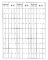
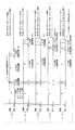
そして、特別図柄の変動は図10乃至図13のタイムチャートに示すようになっている。なお、左・中・右の各図柄列の変動は、図8(A)の一覧表図に示すパターンに基づいて行われる。変動パターンAは、一定の速度で変動(16.7msに1図柄変動)するパターンであり、変動パターンBは、除々に減速して停止(3図柄変動)するパターンであり、変動パターンCは、除々に減速(3図柄変動)するパターンであり、変動パターンDは、一定の速度で変動(333.3msに1図柄変動、1周期5.000秒)するパターンであり、変動パターンEは、除々に減速して停止(1図柄変動)するパターンであり、変動パターンFは、除々に減速して停止(1図柄変動)するパターンであり、変動パターンGは、除々に減速(1図柄変動)するパターンであり、変動パターンHは、除々に加速・減速して停止するパターンであり、変動パターンIは、除々に減速して停止するパターンであり、変動パターンJは、除々に加速・減速(4.875図柄)するパターンである。また、図10乃至図13の各タイムチャート中に記載の条件1〜3、※、及び※1〜6は、図8(B)及び図9の各一覧表図に示すものである。
【0022】
先ず、特別可変表示装置30の変動動作において、リーチせずに外れ又はリーチして外れる場合の図柄列の変動を図10及び図11のタイムチャートに基づいて説明する。図10において、普通可変入賞球装置5に打玉が入賞し始動玉検出器8が始動信号を導出すると、その始動信号の立ち上がり時に、WCRND1から数値を抽出してこれを格納する。その後、始動信号の立ち上がりより0.002秒後には、WCRND_L・C・Rから数値を抽出すると共に、格納したWCRND1の読み出し及び判定を行う。なお、このとき、リーチとなる場合は、WCRND_ACTから数値を抽出する。そして、始動信号の立ち上がりより0.004秒後に、左・中・右の全図柄列を変動パターンAにて変動させる。その後、左図柄列は、4.600秒間変動パターンAにて変動された後、1.250秒間変動パターンBにて変動され、次に後述する変動パターンSで2.100〜19.114秒間変動されて停止する。また、右図柄列は、5.850秒間変動パターンAにて変動された後、1.250秒間変動パターンBにて変動され、次に後述する変動パターンSで0.850〜17.864秒間変動されて停止する。なお、このような左・右の各図柄の変動パターンAにおいて、※4のとき、即ち始動口入賞による記憶が3以上ある場合には、変動時間がそれぞれ3.100秒及び4.350秒に短縮され、※5のとき、即ち高確率時において始動口入賞による記憶が2以上ある場合には、変動時間がそれぞれ1.000秒及び2.250秒に短縮される。
【0023】
一方、中図柄は、リーチ以外のとき、7.100秒間変動パターンAにて変動された後、0.850秒間変動パターンBにて変動されて停止表示される。なお、リーチ以外での中図柄の変動パターンAにおいて、※4のときには変動時間が5.600秒に短縮され、※5のときには変動時間が3.500秒に短縮される。また、リーチ1での中図柄は、図11に示すように、変動パターンAでの7.100秒間の変動の後に、0.420秒間の変動パターンC及び5.664〜10.340秒間の変動パターンDにて変動され、その後1.184秒間変動パターンEにて変動された後に停止表示される。リーチ2・3での中図柄は、変動パターンAでの7.100秒間の変動の後に、0.420秒間の変動パターンC及び14.675〜15.340秒間の変動パターンDにて変動され、その後1.184秒間変動パターンEにて変動された後に停止表示される。リーチ4での中図柄は、変動パターンAでの7.100秒間の変動の後に、0.420秒間の変動パターンC及び14.672秒間の変動パターンDにて変動され、その後2.660秒間変動パターンFにて変動された後に停止表示される。リーチ5での中図柄は、変動パターンAでの7.100秒間の変動の後に、0.420秒間の変動パターンC及び13.670秒間の変動パターンDにて変動され、その後2.354〜3.390秒間変動パターンHにて変動された後に停止表示される。
【0024】
なお、上記したリーチ1〜5での中図柄の変動パターンAにおいて、※3のとき、即ち図柄変動中にスピンをする場合には、変動時間が9.290秒となり、※4のときには変動時間が5.690秒に短縮され、※7のとき、即ち※4であり且つ図柄変動中にスピンをする場合には、変動時間が7.790秒となる。また、外れとなるときのリーチ1〜5の選択及び図柄変動中にスピンをするか否かの決定は、条件1〜3及び※6の条件に基づいて行われる。例えば、大当り図柄の1図柄手前で停止(条件1)であり、且つWCRND_ACTの抽出値が「0〜18」の何れかの場合には、リーチ1を選択し且つ図柄変動中にスピンさせる。また、大当り図柄の1図柄後で停止(条件2)であり、且つWCRND_ACTの抽出値が「124〜127」の何れかの場合には、リーチ5を選択し且つ図柄変動中にスピンさせない。
【0025】
次に、特別可変表示装置30の変動動作において、大当りとなる場合の図柄列の変動を図12及び図13のタイムチャートに基づいて説明する。図12において、普通可変入賞球装置5に打玉が入賞し始動玉検出器8が始動信号を導出すると、その始動信号の立ち上がり時に、WCRND1から数値を抽出してこれを格納する。その後、始動信号の立ち上がりより0.002秒後には、格納したWCRND1の読み出し及び判定を行うと共に、WCRND_L・C・R・ACTからそれぞれ数値を抽出する。そして、始動信号の立ち上がりより0.004秒後に、左・中・右の全図柄列を変動パターンAにて変動させる。その後、左図柄列は、4.600秒間変動パターンAにて変動された後、1.250秒間変動パターンBにて変動され、次に後述する変動パターンSで2.100〜19.264秒間変動されて停止する。また、右図柄列は、5.850秒間変動パターンAにて変動された後、1.250秒間変動パターンBにて変動され、次に後述する変動パターンSで0.850〜18.014秒間変動されて停止する。なお、このような左・右の各図柄の変動パターンAにおいて、※4のときには、変動時間がそれぞれ3.100秒及び4.350秒に短縮され、※5のときには、変動時間がそれぞれ1.000秒及び2.250秒に短縮される。
【0026】
一方、中図柄は、リーチ1のとき、図13に示すように、変動パターンAでの7.100秒間の変動の後に、0.420秒間の変動パターンC及び10.006秒間の変動パターンDにて変動され、その後1.184秒間変動パターンEにて変動された後に停止表示される。リーチ2・3での中図柄は、変動パターンAでの7.100秒間の変動の後に、0.420秒間の変動パターンC及び15.006秒間の変動パターンDにて変動され、その後1.184秒間変動パターンEにて変動された後に停止表示される。リーチ4での中図柄は、変動パターンAでの7.100秒間の変動の後に、0.420秒間の変動パターンC及び14.672秒間の変動パターンDにて変動され、その後2.660秒間変動パターンIにて変動された後に停止表示される。リーチ5での中図柄は、変動パターンAでの7.100秒間の変動の後に、0.420秒間の変動パターンC、13.670秒間の変動パターンD、及び0.384秒間の変動パターンGにて変動され、その後2.354〜3.390秒間変動パターンHにて変動された後に停止表示される。リーチ6での中図柄は、変動パターンAでの7.100秒間の変動の後に、0.420秒間の変動パターンC、13.670秒間の変動パターンD、及び0.384秒間の変動パターンGにて変動され、その後2.306秒間変動パターンJにて変動された後、1.234秒(0.875図柄)逆回転されて停止表示される。
【0027】
なお、上記したリーチ1〜6での中図柄の変動パターンAにおいて、※3のときには、変動時間が9.290秒となり、※4のときには変動時間が5.690秒に短縮され、※7のときには、変動時間が7.790秒となる。また、大当りとなるときのリーチ1〜6の選択及び図柄変動中にスピンをするか否かの決定は、WCRND_ACTからの抽出値に基づいて行われる。例えば、WCRND_ACTの抽出値が「0〜7」の何れかの場合には、リーチ1を選択し且つ図柄変動中にスピンさせる。また、WCRND_ACTの抽出値が「121〜127」の何れかの場合には、リーチ6を選択し且つ図柄変動中にスピンさせない。また、以上のような大当りでの図柄変動においては、前記WCRND_ACT及びWCRND_Kの各抽出値に基づいて大当り図柄の仮停止表示が行われるものであり、この大当り図柄の仮停止表示については後に詳述する。
【0028】
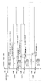
次に、上記した左・右の各図柄における変動パターンSを図14のタイムチャートに基づいて説明する。なお、変動パターンSは、図14に示す「A.上下移動」の変動パターンS1から構成されているが、他の実施形態として「B.スロー回転」の変動パターンS2、「C.一旦停止と再回転」の変動パターンS3、あるいは「D.停止」の変動パターンS4を変動パターンSとしてもよい。また、図14では、変動パターンS(S1〜S4)で「4」の図柄が変動された後T2時間(例えば、0.5秒)「4」の図柄で停止され(大当り図柄の仮停止表示)、その後正回転によって「7」の図柄で大当りする場合を例示している。変動パターンS1は、1図柄分の上下方向における狭い領域で正回転と逆回転とを周期T1で繰り返す変動であり、見た目には「4」の図柄が上下方向に振動しているように表示される。変動パターンS2は、「4」の図柄の下半分の位置から低速の正回転を行う変動であり、その後のT2時間の停止では「4」の図柄の上半分が表示される。変動パターンS3は、「4」の図柄で微少時間停止させた後に図柄を高速で1周回転させて再度「4」の図柄で微少時間停止させる動作を繰り返す変動である。変動パターンS4は、「4」の図柄を継続的に停止表示させるものであり、ここでは便宜的に「変動パターン」という記載を行っている。なお、変動パターンSは、上記したもの以外に左右運動、拡大縮小運動、回転運動、あるいは変形運動を行うものであってもよい。
【0029】
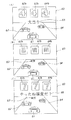
次に、キャラクタ画像表示部60に表示される具体的な図柄変動画像について図15乃至図17を参照して説明する。なお、本実施形態では、「カーレース」をゲームコンセプトに採用することで、キャラクタ画像表示部60に表示するキャラクタ画像もこれに基づいたものとなっている。即ち、図15(A)に示すように、レーシングカー61が遊技者用のキャラクタ画像となる一方で、レーシングカー61の前方に表示される3台のレーシングカー62〜64が相手方のキャラクタ画像となり、これら4台のレーシングカー61〜64が表示画面上であたかもカーレースを行うような表示となっている。また、レーシングカー62〜64上には、それぞれ左・中・右の各特別図柄表示部62a・63a・64aが設けられており、これら特別図柄表示部62a・63a・64aでは、それぞれ左・中・右の各特別図柄が可変表示されるようになっている。そして、図15(B)に示すように、各特別図柄表示部62a・63a・64aで図柄変動が行われているなか、レーシングカー61が先ず左側のレーシングカー62に体当たりする。これにより、左特別図柄表示部62aの変動が停止すると共に、この変動停止した左図柄が表示画面の上部左側に左確定図柄62bとして表示される(図15(C)参照)。その後は、同様にしてレーシングカー61が右側及び中側の各レーシングカー64・63に順次体当たりすることで、右・中の各図柄が表示画面の上部右側及び上部中央に右・中の各確定図柄64b・63bとして表示される(図16(A)参照)。なお、図16(A)は、リーチせずに外れが確定した場合の表示画像である。また、左・右の各確定図柄62b・64bにおいては、当り外れ及びリーチ変動の有無に関係なく中図柄が確定されるまでの間、前述した変動パターンSに基づく変動を行うものである。
【0030】
次に、リーチ変動後に大当りとなる場合でのキャラクタ画像の表示を説明する。なお、リーチ変動時には、前記WCRND_ACTの抽出値に応じてレーシングカー61が図16(B)に示すように一度スピン表示されるものである。大当りとなる場合では、先ず、前述したリーチしない場合と同様の各図柄変動を行うなかで、左・右の各確定図柄62b・64bが同一に揃ってリーチ表示が行われる(図16(C)参照)。そして、図17(A)に示すように、中図柄が左・右の各確定図柄62b・64bと同一の図柄で停止表示されると共に「大当り」の文字65が表示されて大当りが確定される。また、WCRND_ACT及びWCRND_Kの各抽出値に基づいて大当り図柄の変更が行われる場合には、図17(A)の図柄が大当り図柄の仮停止表示となり、その後各確定図柄62b・63b・64bが各々の表示位置で再変動される(図17(B)参照)。そして、再変動後の各確定図柄62b・63b・64bが、図17(C)に示すように確変図柄で停止表示されると、「やったね確変だ!」の文字66が表示されて確率変動が確定される。
【0031】
なお、複数種類のリーチは、本実施形態に限らず、表示内容、変動速度、変動時間、停止順序、効果音等を変えてもよく、さらには組合せてもよい。さらに、本実施形態では、キャラクタ画像表示部60で可変表示するキャラクタ画像(レーシングカー)に特別図柄表示部62a・63a・64aを設けると共に該特別図柄表示部62a・63a・64aで各特別図柄を変動し、これら特別図柄が所定の大当り組合せとなったときを本発明の予め定めた表示結果としているが、特にこのようにキャラクタ画像表示部60で特別図柄を変動させるものに限定する必要はない。例えば、キャラクタ画像表示部60で可変表示するキャラクタ画像を、複数のパズル片としたり、人物画像としても構わない。複数のパズル片をキャラクタ画像とした場合での予め定めた表示結果とは、全パズル片により所定の図柄が完成された場合であり、人物画像をキャラクタ画像とした場合での予め定めた表示結果とは、人物画像が他の人物画像と勝負して勝った場合や人物画像が画面上所定の目的地点へ到達した場合である。また、複数のパズル片をキャラクタ画像とした場合でのリーチ状態は、パズルの完成度に応じた設定であり、人物画像をキャラクタ画像とした場合でのリーチ状態は、勝負や移動の過程度合いに設定することができる。
【0032】
次に、上記した大当り図柄の仮停止表示を含む図柄の表示制御を図18のフローチャートに基づいて説明する。図18において、先ず、WCRND1、WCRND_L・C・R、及びWCRND_Kの抽出を行うと(S1)、抽出したWCRND1の値が大当り値か否かを判別する(S2)。S2でWCRND1の値が外れ値の場合は、次にWCRND_Lの値がWCRND_Rの値と同一か否か、即ちリーチの有無を判別する(S3)。S3でリーチがない場合は後述のS6に直接移行する一方、リーチがある場合はWCRND_ACTの抽出を行った後に(S4)、このWCRND_ACTの値と前記図8(B)の条件とに基づいたリーチ動作を選択し、このリーチ動作実行フラグをセットして(S5)、S6に移行する。そして、S6では、WCRND_L・C・Rの値に応じた外れ表示位置フラグをセットする。
【0033】
一方、前記S2でWCRND1の値が大当り値の場合は、大当りフラグをセットする。そして、WCRND_ACTの抽出を行った後に(S7)、前記S1で抽出したWCRND_Lの値が確変値であるか否かを判別する(S8)。S8でWCRND_Lの値が確変値でない場合は後述のS11に移行する一方、S8でWCRND_Lの値が確変値の場合は次にWCRND_ACTの値が偶数か否かを判別する(S9)。S9でWCRND_ACTの値が偶数の場合は、このWCRND_ACTの値と前記図8(B)の条件とに基づいたリーチ動作を選択してこのリーチ動作実行フラグをセットし(S10)、その後S14に移行してWCRND_Lの値に応じた大当りの表示位置フラグをセットする。一方、S9でWCRND_ACTの値が奇数の場合は、S11に移行してWCRND_ACTの値と前記図8(B)の条件とに基づいたリーチ動作してこのリーチ動作実行フラグをセットする。その後、前記S1で抽出したWCRND_Kの値に応じた仮停止表示位置で一旦停止位置フラグをセットし(S12)、その後図柄の再変動フラグをセットして(S13)、最終的にWCRND_Lの値に応じた大当りの表示位置フラグをセットする(S14)。そして、上記のフラグ値に基づいて図柄の変動表示が実行される。
【0034】
以上のように、本実施形態の遊技機は、特別可変表示装置30の表示結果を導出以前に決定する乱数テーブルとしてWCRND1及びWCRND_L・C・Rを備えると共に、これらの乱数テーブルで決定した表示結果が大当り図柄(特定表示結果)となる場合、複数種類のうちのいずれかの大当り図柄を仮表示結果として決定する乱数テーブルとしてWCRND_Kを備えており、大当り図柄の変更表示を可能にしている。また、このような大当り図柄の変更表示においては、前記図18のS8及びS9の各判定ステップに示したように、最終停止する大当り図柄が確変図柄以外のときは図柄の変更表示を100%行う一方、最終停止する大当り図柄が確変図柄のときは図柄の変更表示を50%行うようになっており、さらには、WCRND_Kの値に基づいて仮停止表示する大当り図柄は、確変図柄以外となっている。これにより、確変図柄以外で大当りしたときには必ず図柄の変更表示が行われるので、遊技者に対して確変が発生するチャンスを再度与えるかのような図柄の表示制御を行うようになっている。従って、遊技者は特定遊技状態の発生を事前に認識した後に確変の有無が分かり、ひいては遊技の興趣を向上するようになっている。
【0035】
なお、本実施形態では、最終停止する大当り図柄が確変図柄のときに図柄の変更表示を50%の確率で実行するために表示変更決定手段としてWCRND_ACTの値を用いているが、このような表示変更の実行確率及び表示変更決定手段は、実施形態中のものに限定するものではない。例えば、実施形態中に記載のWCRND_Cを表示変更決定手段として兼用したり、あるいは決定用に別の乱数テーブルを設けてもよい。また、本実施形態では、大当り図柄の仮停止表示用にWCRND_Kの乱数テーブルを設けているが、これに限らず他の乱数テーブルを仮停止表示用に兼用してもよい。仮停止表示用に乱数テーブルを兼用した場合での図柄の表示制御を図19のフローチャートに基づいて説明すると、図19において、先ず、WCRND1、WCRND_L・C・R、及びWCRND_Kの抽出を行うと(S21)、抽出したWCRND1の値が大当り値か否かを判別する(S22)。S22でWCRND1の値が外れ値の場合は、次にWCRND_Lの値がWCRND_Rの値と同一か否か、即ちリーチの有無を判別する(S23)。S23でリーチがない場合は後述のS26に直接移行する一方、リーチがある場合はWCRND_ACTの抽出を行った後に(S24)、このWCRND_ACTの値と前記図8(B)の条件とに基づいたリーチ動作を選択し、このリーチ動作実行フラグをセットして(S25)、S26に移行する。そして、S26では、WCRND_L・C・Rの値に応じた外れ表示位置フラグをセットする。
【0036】
一方、前記S22でWCRND1の値が大当り値の場合は、大当りフラグをセットする。そして、WCRND_ACTの抽出を行った後に(S27)、このWCRND_ACTの値が偶数か否かを判別する(S28)。S28でWCRND_ACTの値が偶数の場合は、このWCRND_ACTの値と前記図8(B)の条件とに基づいたリーチ動作を選択してこのリーチ動作実行フラグをセットし(S29)、その後S36に移行してWCRND_Lの値に応じた大当りの表示位置フラグをセットする。一方、S28でWCRND_ACTの値が奇数の場合は、S30に移行してWCRND_ACTの値と前記図8(B)の条件とに基づいたリーチ動作を選択してこのリーチ動作実行フラグをセットする。その後、A(=WCRND_L−WCRND_C)の値を算出し(S31)、|A|の値(Aの絶対値)が「1・3・5・7・9」のいずれかの値であるか否かを判定する(S32)。S32で|A|の値が「1・3・5・7・9」のいずれの値でもないときは直接S34に移行する一方、|A|の値が「1・3・5・7・9」のいずれかのときは|A|の値に「1」を加えてS34に移行する。即ち、上記したS31〜S33の各ステップでは、前記図18のようにWCRND_Kを設けることなく、A(=WCRND_L−WCRND_C)の値を仮停止表示用の乱数として用いている。そして、S34で|A|の値に応じた仮停止表示位置(図5の表に対応した図柄停止表示位置)フラグをセットし、その後図柄の再変動フラグをセットして(S35)、最終的にWCRND_Lの値に応じた大当りの表示位置フラグをセットする(S36)。そして、上記のフラグ値に基づいて図柄の変動表示が実行される。
【0037】
なお、図19の図柄表示制御では、前記S28の判定ステップにより最終停止する大当り図柄が確変図柄以外の場合あるいは最終停止する大当り図柄が確変図柄の場合、いずれの場合においても図柄の変更表示を50%の確率で行うようになっている。また、このような最終停止する大当り図柄が確変図柄以外の場合あるいは最終停止する大当り図柄が確変図柄の場合での図柄変更確率は、図18及び図19に示すものに限らず、最終停止する大当り図柄が確変図柄であるか否かに関わらず全ての大当り図柄を変更表示したり、または全ての大当り図柄のうちの一部で変更表示を行ってもよい。
【0038】
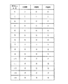
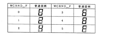
次に、前記普通図柄表示器34に表示される普通図柄について説明する。普通図柄は、図20に示すように、「0・2・4・6・8・F」の6種類であり、1図柄の表示時間を0.040秒とした1周期(0.240秒)で変動表示される。また、これらの普通図柄に対しては、図21に示すように、0.002秒毎に1ずつ加算される当り決定用のWCRND2(3〜13)と、0.002秒毎に1ずつ加算され且つ割り込み処理余り時間に1ずつ加算される普通図柄表示用のWCRND_F(0〜5)と、が設けられている。WCRND_F(0〜5)の各ランダム数は、図22に示すように、「0・2・4・6・8・F」の各普通図柄に対応して設けられている。また、WCRND2(3〜13)からのランダム数の抽出において、図23に示すように、「3」の値が抽出されて当りと判定されると、普通図柄表示器34にWCRND_Fデータの「5」に対応する「F」の当り図柄を表示して普通可変入賞球装置5を所定時間開放(入賞口の拡大)する。一方、WCRND2で「3」以外の値が抽出されて外れと判定されると、WCRND_Fデータの値を抽出し、この値に対応する外れ図柄を普通図柄表示器34に表示する。なお、WCRND2で外れと判定されたにも関わらずWCRND_Fで抽出された値が偶然にも当り図柄となる場合には、「0」の外れ図柄を選択してこれを普通図柄表示器34に表示するものである。また、上記WCRND2からの抽出データの判定は、当り確率が通常時の場合であり、前記特別図柄と同様の確変時(高確率時)には、WCRND2から抽出された値が「3〜12」のうち何れかの値で当りと判定する一方、それ以外の「13」の値で外れと判定するようになっている。
【0039】
次に、上記した普通図柄表示器34での普通図柄の変動動作を図24乃至図26のタイムチャートに基づいて説明する。先ず、図24において、通過玉検出器15(図24中には、始動玉検出器と記載)がONすると、これと同時にWCRND2及びWCRND_Fの抽出及び格納が行われる。その後、通過玉検出器15のONから所定時間(0.002秒)が経過すると、格納したWCRND2の読み出し及び判定を行い、その0.002秒後に普通図柄の変動を開始する。そして、通過玉検出器15のONから所定時間(29.500秒)後に変動を停止する。なお、図24に示す条件1である確率変動時には、普通図柄の変動時間が5.000秒に短縮され、図24に示す条件2である確率変動時に普通図柄の始動記憶が3個以上ある場合には、普通図柄の変動時間が2.000秒に短縮されるものである。そして、通常時(低確率時)において停止表示される普通図柄が当り図柄のときには、図25(A)に示すように、普通図柄が停止してから所定時間(0.500秒)後に普通可変入賞球装置5を0.500秒間開放する。その後、通過玉検出器15への通過記憶がある場合には、普通可変入賞球装置5の閉鎖から0.002秒後に、格納したWCRND2の読み出し及び判定を行い、その0.002秒後に再度普通図柄の変動を開始する。なお、このときの普通可変入賞球装置5の開放動作は0.500秒間ではあるが、入賞玉が1個入れば時間に満たなくてもその時点で開放を終了するものである。また、確率変動時(高確率時)において停止表示される普通図柄が当り図柄のときには、図25(B)に示すように、普通図柄が停止してから所定時間(0.500秒)が経過すると普通可変入賞球装置5を2.900秒間開放し、2.000秒のインターバルを置いた後に再度2.900秒間開放する。その後、通過玉検出器15への通過記憶がある場合には、普通可変入賞球装置5の閉鎖から0.002秒後に、格納したWCRND2の読み出し及び判定を行い、その0.002秒後に再度普通図柄の変動を開始する。一方、停止表示される普通図柄が外れ図柄となった後に通過玉検出器15への通過記憶がある場合には、図26に示すように、普通図柄が停止してから所定時間(1.002秒)後に格納したWCRND2の読み出し及び判定を行い、その0.002秒後に再度普通図柄の変動を開始する。
【0040】
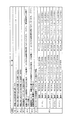
次に、特別図柄及び普通図柄の確率変動について説明すると、図27に示すように、大当り時(条件装置の作動時)に特別可変表示装置30に「1」「3」「5」「7」「9」のうちいずれかの同一図柄のゾロ目(大当り図柄であり且つ確変図柄)が停止表示されて大当り遊技状態となると、その後、無条件に確率変動が所定回数(図27では2回)繰り返し行われる。この確率変動は、確変図柄での特定遊技状態(大当り遊技状態)発生の終了を契機に高確率に変動させた後、確変図柄以外での特定遊技状態の発生を契機に通常時の確率に戻す。また、確変時に再度確変図柄で大当りした場合には、その時点から再度確率変動が所定回数(2回)繰り返される。
【0041】
なお、本実施形態では、本発明の特別表示結果を特別可変表示装置30での確変図柄の表示とすると共に、特別表示結果に伴う特別の遊技価値を特別図柄及び普通図柄の各確率変動としているが、特にこれに限定するものではない。例えば、特別図柄又は普通図柄いずれか一方の確率変動、特別図柄及び普通図柄の各短縮変動、特別図柄又は普通図柄いずれか一方の短縮変動、普通電役の開放時間の変更(例えば、0.5秒から3秒に変更)、あるいは普通電役の開放回数の変更(例えば、0.5秒の開放を1回から0.5秒の開放を6回に変更)を特別の遊技価値とすることも可能である。また、本実施形態では、特別の遊技価値を付与し得る特別表示結果(確変図柄)を特定遊技状態を発生させる特定表示結果(大当り図柄)内に包含させた構成としているが、特にこれに限定するものではなく、所定の遊技価値を付与し得る特別可変表示装置30の表示結果を特定表示結果(大当り図柄)のみに限定し、大当り図柄の仮停止表示を行ってもよい。この場合では、大当り図柄の表示において複数種類のうち予めホール側で決めた大当り図柄(持たせ図柄)が停止表示されることにより景品玉の継続使用を許可することを大当りに伴う付加的な遊技価値とすることができるため、大当り図柄の変更に伴う遊技の興趣向上を招来することができる。
【0042】
また、上記した実施形態は、本発明を限定するものではなく、本発明の範囲内で種々の変更が可能である。例えば、本実施形態では、特別可変表示装置30をLCD表示器33にて構成しているが、特にこれに限定するものではなく、CRT、LED、VFD、EL、あるいはプラズマによる表示器や、ドラム式、ベルト式、あるいはリーフ式にて構成することも可能である。また、遊技機全体をLCD表示器等の表示装置にて構成する、即ち「打玉」「可変入賞球装置」等の構成部材を疑似的に表示器に表示することで遊技機を構成することも可能である。なお、この場合では、賞球の払出しを得点等で代行しても良い。
【0043】
【発明の効果】
以上、説明したところから明らかなように、本発明の請求項1においては、識別情報を個々に可変表示する複数の表示部を画像で表示する可変表示装置を備え、前記複数の表示部の識別情報を確定して導出する表示結果が複数種類のうちのいずれかの特定表示結果として導出されると、これに基づいて特定遊技状態を発生して遊技者に特定の遊技価値を付与し得る弾球遊技機において、前記複数の表示部に表示される表示結果を導出以前に決定する表示結果決定手段と、該表示結果決定手段で決定された表示結果が前記複数種類のうちの前記特定表示結果となる確率が通常時よりも高い確率に変更された遊技状態である確率変動の発生する前記特定表示結果となる場合に、該確率変動の発生する特定表示結果と前記確率変動の発生しない特定表示結果のいずれかを仮表示結果として決定する仮表示結果決定手段と、該表示結果決定手段で決定された表示結果となるように前記複数の表示部の変動を制御する変動制御手段と、を備え、前記変動制御手段は、前記表示結果決定手段によって決定された表示結果が前記特定表示結果であると判定された場合に、前記複数の表示部のうち最後に識別情報が導出される表示部を除く表示部に前記仮表示結果決定手段で決定した前記確率変動の発生する特定表示結果と前記確率変動の発生しない特定表示結果のいずれかとなる識別情報を導出し、その導出した識別情報を最後に識別情報が導出さ れる表示部の変動が停止されるまでの間所定の変動パターンでの変動を実行した後、すべての表示部において前記仮表示結果決定手段で決定した前記確率変動の発生する特定表示結果と前記確率変動の発生しない特定表示結果のいずれかとなる識別情報で仮停止表示し、その後すべての表示部を再変動して前記確率変動の発生する特定表示結果となる識別情報で停止表示される変動を実行することを特徴とする。このように構成することにより、特定表示結果となる場合に、複数の表示部で表示される識別情報が最終的に同時に確定されるように変動することができる。
【図面の簡単な説明】
【図1】 本発明の一実施形態における遊技盤を示す正面図である。
【図2】 遊技動作を制御する制御回路を示すブロック図の一部である。
【図3】 遊技動作を制御する制御回路を示すブロック図の一部である。
【図4】 特別図柄の種類を示す一覧表図である。
【図5】 大当り図柄の種類を示す一覧表図である。
【図6】 特別図柄の変動に用いられる各種ランダム数の一覧表図である。
【図7】 選択されたランダム数によって特別図柄の当り外れを決定する動作を説明するための簡単なフローチャートである。
【図8】 同図(A)は特別図柄の変動パターンを示す一覧表図であり、また、同図(B)は特別図柄の変動条件を示す一覧表図である。
【図9】 特別図柄の変動における注記事項を示す一覧表図である。
【図10】 リーチせずに外れ又はリーチして外れる場合での左・中・右の各図柄列の変動動作を示すタイムチャートである。
【図11】 リーチせずに外れ又はリーチして外れる場合での中図柄列の変動動作を示すタイムチャートである。
【図12】 大当りとなる場合での左・中・右の各図柄列の変動動作を示すタイムチャートである。
【図13】 大当りとなる場合での中図柄列の変動動作を示すタイムチャートである。
【図14】 変動パターンSを示すタイムチャートである。
【図15】 同図(A)〜(C)は、各々、図柄変動における具体的な表示画像を示す説明図である。
【図16】 同図(A)〜(C)は、各々、図柄変動における具体的な表示画像を示す説明図である。
【図17】 同図(A)〜(C)は、各々、図柄変動における具体的な表示画像を示す説明図である。
【図18】 図柄表示の制御プロセスを示すフローチャートである。
【図19】 他の実施形態における図柄表示の制御プロセスを示すフローチャートである。
【図20】 普通図柄の種類を示す一覧表図である。
【図21】 普通図柄の変動に用いられる各種ランダム数の一覧表図である。
【図22】 普通図柄とWCRND_Fとの関係を示す一覧表図である。
【図23】 選択されたランダム数によって普通図柄の当り外れを決定する動作を説明するための簡単なフローチャートである。
【図24】 通過玉検出器での通過検出に伴う普通図柄の変動動作を示すタイムチャートである。
【図25】 同図(A)は通常時において普通図柄が当りとなるときの普通可変入賞球装置の開放動作を示すタイムチャートであり、また、同図(B)は高確率時において普通図柄が当りとなるときの普通可変入賞球装置の開放動作を示すタイムチャートである。
【図26】 普通図柄が外れとなった後に普通図柄が再変動する動作を示すタイムチャートである。
【図27】 確変図柄の停止表示による確率変動の動作を示すタイムチャートである。
【符号の説明】
1 遊技盤
3 遊技領域
5 普通可変入賞球装置
8 始動玉検出器
9 特別可変入賞球装置
11 開閉板
12 特定玉検出器
13 入賞玉検出器
15 通過玉検出器
19 特定玉入賞表示LED
30 特別可変表示装置(可変表示装置)
33 LCD表示器
34 普通図柄表示器
35 普通図柄記憶表示LED
36 特別図柄記憶表示LED
42 基本回路(表示変更制御手段)
60 キャラクタ画像表示部
62a・63a・64a 特別図柄表示部
62b・63b・64b 確定図柄[0001]
BACKGROUND OF THE INVENTION
The present invention includes a variable display device that displays a plurality of display units that individually display identification information in an image, and the display result for determining and deriving the identification information of the plurality of display units is any of a plurality of types. When it is derived as the specific display result, the present invention relates to a ball game machine that can generate a specific game state based on this result and give a specific game value to the player.
[0002]
[Problems to be solved by the invention]
It is an object of the present invention to provide a ball game machine in which identification information displayed on a plurality of display units is finally determined simultaneously in a variable display device that displays a plurality of display units as images. There is to do.
[0003]
[Means for Solving the Problems]
In order to achieve the above object, the solution adopted by
[0004]
Further , in the second to fourth aspects of the present invention, as the predetermined variation pattern, a variation pattern in which the predetermined identification information moves up and down, a variation pattern in which the predetermined identification information varies at a low speed, and predetermined identification information are included. It is possible to obtain a variation pattern that repeats the variation in which the one identification information is stopped and displayed again by stopping and displaying for a predetermined time and then rotating once.
[0005]
In addition, by the pachinko gaming machine provided with the
[0006]
Moreover, the structure of the display result determination means based on this invention is illustrated by WCRND1 and WCRND_L * C * R which are shown in FIG. Moreover, the structure of the temporary display result determination means according to the present invention is illustrated by WCRND_K shown in FIG.
[0007]
In addition, the plurality of display units so as to obtain the display results determined by the display result determining means by the variation control of the left symbol, the right symbol, and the middle symbol shown in FIG. 10, FIG. 11, FIG. 12, FIG. 1 illustrates the configuration of a variation control means for controlling the variation of the.
[0008]
In addition, when the display result determined by the display result determination unit is determined to be the specific display result according to the variation pattern S illustrated in FIG. 12 , the identification information is derived last among the plurality of display units. Deriving identification information that is one of the specific display result in which the probability variation is determined and the specific display result in which the probability variation is not determined in the display unit other than the display unit is determined, and the derived identification A configuration in which a predetermined variation pattern is executed until the variation of the display unit from which the identification information is finally derived is stopped is illustrated , and all of S2, S7 to S9, and S11 to S14 illustrated in FIG. stop provisional identification information as the one of specific display results and the probability change specific display results that do not occur in the generation of the probability change determined in the temporary display result determining unit in the display unit Displaying illustrates a configuration for performing the variations that appear then quenched with specific display result becomes identification information generated for all of the display unit again varies with the probability varying.
[0009]
DETAILED DESCRIPTION OF THE INVENTION
Hereinafter, embodiments of the present invention will be described with reference to the drawings. First, with reference to FIG. 1, the structure of the
[0010]
Below the special
[0011]
A special variable winning
[0012]
A projecting member 16 having a
[0013]
Thus, the special variable winning
[0014]
In addition to the above-described configuration, the surface of the
[0015]
Next, the configuration of the special
[0016]
The left, middle and right special symbols displayed on the character
[0017]
The configuration of the
[0018]
On the other hand, the
[0019]
Next, the special symbol changing operation by the special
[0020]
Then, as shown in FIG. 7, when the value extracted from WCRND1 is “3” and it is determined that the jackpot is determined, the jackpot symbol is determined by the data of WCRND_L (0 to 14), and this jackpot symbol is displayed as a special variable display. It is displayed on the
[0021]
The variation of the special symbol is as shown in the time charts of FIGS. Note that the variation of each of the left, middle, and right symbol sequences is performed based on the pattern shown in the list diagram of FIG. The fluctuation pattern A is a pattern that fluctuates at a constant speed (one symbol fluctuation in 16.7 ms), the fluctuation pattern B is a pattern that gradually decelerates and stops (three symbol fluctuations), and the fluctuation pattern C is The pattern gradually decelerates (three symbol variations), the variation pattern D is a pattern that varies at a constant speed (one symbol variation in 333.3 ms, one cycle of 5.000 seconds), and the variation pattern E gradually Is a pattern that decelerates and stops (one symbol variation), variation pattern F is a pattern that gradually decelerates and stops (one symbol variation), and variation pattern G gradually decelerates (one symbol variation). The variation pattern H is a pattern that gradually accelerates and decelerates to stop, the variation pattern I is a pattern that gradually decelerates and stops, and the variation pattern J gradually accelerates. A pattern for decelerating (4.875 symbol). Further, the
[0022]
First, in the changing operation of the special
[0023]
On the other hand, the middle symbol is changed in the fluctuation pattern A for 7.100 seconds and is changed in the fluctuation pattern B for 0.850 seconds, and is stopped and displayed, except for the reach. In the middle symbol variation pattern A other than reach, the variation time is shortened to 5.600 seconds when * 4, and the variation time is shortened to 3.500 seconds when * 5. In addition, as shown in FIG. 11, the middle symbol in
[0024]
In the above-described medium symbol variation pattern A in
[0025]
Next, in the changing operation of the special
[0026]
On the other hand, in the case of
[0027]
In the middle symbol variation pattern A in the
[0028]
Next, the fluctuation pattern S in each of the above left and right symbols will be described based on the time chart of FIG. The variation pattern S is composed of the variation pattern S1 of “A. Vertical movement” shown in FIG. 14, but as another embodiment, the variation pattern S2 of “B. Slow rotation”, “C. The variation pattern S3 of “re-rotation” or the variation pattern S4 of “D. stop” may be used as the variation pattern S. Further, in FIG. 14, after the symbol “4” is varied in the variation pattern S (S1 to S4), it is stopped at the symbol “4” for T2 time (for example, 0.5 seconds) (a temporary stop display of the big hit symbol) ), And then a big hit with the symbol “7” by forward rotation. The fluctuation pattern S1 is a fluctuation in which a normal rotation and a reverse rotation are repeated at a cycle T1 in a narrow area in the vertical direction for one symbol, and is visually displayed as if the symbol “4” vibrates in the vertical direction. The The fluctuation pattern S2 is a fluctuation in which a low-speed forward rotation is performed from the position of the lower half of the symbol “4”, and the upper half of the symbol “4” is displayed at the subsequent stop of the time T2. The fluctuation pattern S3 is a fluctuation that repeats the operation of stopping the symbol for “4” for a minute time, rotating the symbol once at a high speed, and then stopping again for a minute time for the symbol “4”. The variation pattern S4 continuously stops and displays the symbol “4”. Here, for convenience, the “variation pattern” is described. The variation pattern S may be one that performs a left-right motion, an enlargement / reduction motion, a rotational motion, or a deformation motion other than those described above.
[0029]
Next, a specific symbol variation image displayed on the character
[0030]
Next, the display of a character image in the case of a big hit after the reach change will be described. When the reach changes, the
[0031]
Note that the plurality of types of reach are not limited to the present embodiment, and the display content, change speed, change time, stop order, sound effect, and the like may be changed or further combined. Further, in the present embodiment, special
[0032]
Next, the display control of symbols including the temporary stop display of the jackpot symbol will be described based on the flowchart of FIG. In FIG. 18, first, when WCRND1, WCRND_L · C · R, and WCRND_K are extracted (S1), it is determined whether or not the extracted value of WCRND1 is a jackpot value (S2). If the value of WCRND1 is an outlier in S2, it is next determined whether or not the value of WCRND_L is the same as the value of WCRND_R, that is, whether or not there is a reach (S3). If there is no reach in S3, the process proceeds directly to S6 to be described later. If there is a reach, after extracting WCRND_ACT (S4), reach based on the value of WCRND_ACT and the condition of FIG. 8B. The operation is selected, the reach operation execution flag is set (S5), and the process proceeds to S6. In S6, an outlier display position flag corresponding to the value of WCRND_L · C · R is set.
[0033]
On the other hand, if the value of WCRND1 is a big hit value in S2, the big hit flag is set. Then, after extracting WCRND_ACT (S7), it is determined whether or not the value of WCRND_L extracted in S1 is a probability variation value (S8). If the value of WCRND_L is not a probabilistic value in S8, the process proceeds to S11 described later. If the value of WCRND_L is a probable value in S8, it is next determined whether or not the value of WCRND_ACT is an even number (S9). If the value of WCRND_ACT is an even number in S9, the reach operation based on the value of WCRND_ACT and the condition of FIG. 8B is selected and the reach operation execution flag is set (S10), and then the process proceeds to S14. Then, the jackpot display position flag corresponding to the value of WCRND_L is set. On the other hand, if the value of WCRND_ACT is an odd number in S9, the process proceeds to S11 and a reach operation is performed based on the value of WCRND_ACT and the condition of FIG. 8B, and this reach operation execution flag is set. After that, the stop position flag is temporarily set at the temporary stop display position corresponding to the value of WCRND_K extracted in S1 (S12), then the symbol re-variation flag is set (S13), and finally the value of WCRND_L is set. A corresponding jackpot display position flag is set (S14). Based on the above flag value, the symbol variation display is executed.
[0034]
As described above, the gaming machine according to the present embodiment includes WCRND1 and WCRND_L · C · R as random number tables for determining the display result of the special
[0035]
In this embodiment, the value of WCRND_ACT is used as the display change determination means in order to execute the symbol change display with a probability of 50% when the jackpot symbol to be finally stopped is a probabilistic symbol. The execution probability of change and the display change determination means are not limited to those in the embodiment. For example, WCRND_C described in the embodiment may be used as a display change determination unit, or another random number table may be provided for determination. Further, in this embodiment, the WCRND_K random number table is provided for displaying the big hit symbol temporarily stopped. However, the present invention is not limited to this, and another random number table may be used for the temporary stop display. The display control of symbols when the random number table is also used for temporary stop display will be described with reference to the flowchart of FIG. 19. In FIG. 19, first, when extracting WCRND1, WCRND_L · C · R, and WCRND_K ( S21), it is determined whether or not the extracted value of WCRND1 is a big hit value (S22). If the value of WCRND1 is an outlier in S22, it is next determined whether or not the value of WCRND_L is the same as the value of WCRND_R, that is, whether or not there is a reach (S23). If there is no reach in S23, the process proceeds directly to S26, which will be described later. If there is a reach, after extracting WCRND_ACT (S24), the reach based on the value of WCRND_ACT and the condition of FIG. The operation is selected, the reach operation execution flag is set (S25), and the process proceeds to S26. In S26, an outlier display position flag corresponding to the value of WCRND_L · C · R is set.
[0036]
On the other hand, if the value of WCRND1 is a big hit value in S22, a big hit flag is set. Then, after extracting WCRND_ACT (S27), it is determined whether or not the value of WCRND_ACT is an even number (S28). If the value of WCRND_ACT is an even number in S28, the reach operation based on the value of WCRND_ACT and the condition of FIG. 8B is selected and the reach operation execution flag is set (S29), and then the process proceeds to S36. Then, the jackpot display position flag corresponding to the value of WCRND_L is set. On the other hand, if the value of WCRND_ACT is an odd number in S28, the process proceeds to S30 to select a reach operation based on the value of WCRND_ACT and the condition of FIG. 8B and set the reach operation execution flag. Thereafter, the value of A (= WCRND_L−WCRND_C) is calculated (S31), and whether the value of | A | (absolute value of A) is any one of “1, 3, 5, 7, 9”. Is determined (S32). If the value of | A | is not any of "1, 3, 5, 7, 9" in S32, the process proceeds directly to S34, while the value of | A | is "1, 3, 5, 7, 9,""1" is added to the value of | A | and the process proceeds to S34. That is, in each of the above steps S31 to S33, the value of A (= WCRND_L-WCRND_C) is used as a random number for temporary stop display without providing WCRND_K as shown in FIG. In S34, a temporary stop display position (design stop display position corresponding to the table of FIG. 5) flag corresponding to the value of | A | is set, and then a symbol re-variation flag is set (S35). A big hit display position flag corresponding to the value of WCRND_L is set (S36). Based on the above flag value, the symbol variation display is executed.
[0037]
In the symbol display control of FIG. 19, when the jackpot symbol that is finally stopped by the determination step of S28 is other than the probability variation symbol, or when the jackpot symbol that is finally stopped is the probability variation symbol, the symbol change display is 50 in any case. % To do it. Further, the symbol change probability in the case where the jackpot symbol to be finally stopped is other than the probability variation symbol, or in the case where the jackpot symbol to be finally stopped is the probability variation symbol, is not limited to those shown in FIG. 18 and FIG. Regardless of whether or not the symbol is a probable variation symbol, all the jackpot symbols may be changed or displayed, or a change display may be performed on a part of all the jackpot symbols.
[0038]
Next, the normal symbols displayed on the
[0039]
Next, the normal symbol changing operation in the
[0040]
Next, the probability variation of special symbols and normal symbols will be described. As shown in FIG. 27, “1”, “3”, “5”, and “7” are displayed on the special
[0041]
In this embodiment, the special display result of the present invention is displayed as a probability variable symbol on the special
[0042]
Further, the above-described embodiment does not limit the present invention, and various modifications can be made within the scope of the present invention. For example, in the present embodiment, the special
[0043]
【The invention's effect】
As is apparent from the above description, in
[Brief description of the drawings]
FIG. 1 is a front view showing a game board according to an embodiment of the present invention.
FIG. 2 is a part of a block diagram showing a control circuit for controlling a gaming operation.
FIG. 3 is a part of a block diagram showing a control circuit for controlling a gaming operation.
FIG. 4 is a list chart showing the types of special symbols.
FIG. 5 is a list chart showing types of jackpot symbols.
FIG. 6 is a list of various random numbers used for variation of special symbols.
FIG. 7 is a simple flowchart for explaining an operation of determining a hit of a special symbol based on a selected random number.
FIG. 8A is a list chart showing a variation pattern of a special symbol, and FIG. 8B is a list chart showing a variation condition of the special symbol.
FIG. 9 is a table showing notes on special symbol changes.
FIG. 10 is a time chart showing the changing operation of each of the left, middle, and right symbol sequences in the case of detaching without reaching or detaching after reaching.
FIG. 11 is a time chart showing a changing operation of a middle symbol sequence in a case where the detachment is performed without reaching or the detaching is performed after reaching.
FIG. 12 is a time chart showing the changing operation of each of the left, middle and right symbol sequences in the case of a big hit.
FIG. 13 is a time chart showing the changing operation of the middle symbol sequence in the case of a big hit.
14 is a time chart showing a fluctuation pattern S. FIG.
FIGS. 15A to 15C are explanatory diagrams showing specific display images in symbol variation.
FIGS. 16A to 16C are explanatory diagrams showing specific display images in symbol variation. FIG.
FIGS. 17A to 17C are explanatory diagrams showing specific display images in symbol variation.
FIG. 18 is a flowchart showing a control process of symbol display.
FIG. 19 is a flowchart showing a control process of symbol display in another embodiment.
FIG. 20 is a table showing normal symbol types.
FIG. 21 is a list of various random numbers used for variation of normal symbols.
FIG. 22 is a table showing the relationship between normal symbols and WCRND_F.
FIG. 23 is a simple flowchart for explaining an operation of determining a normal symbol hit / off based on a selected random number.
FIG. 24 is a time chart showing a fluctuation operation of a normal symbol accompanying the passage detection by the passage ball detector.
FIG. 25 (A) is a time chart showing the opening operation of the normally variable winning ball apparatus when the normal symbol is a hit in normal time, and FIG. 25 (B) is a normal symbol at high probability. It is a time chart which shows the releasing operation | movement of a normal variable winning ball apparatus when wins.
FIG. 26 is a time chart showing an operation in which the normal symbol is re-variable after the normal symbol is removed.
FIG. 27 is a time chart showing an operation of probability variation by stop display of a probability variation symbol.
[Explanation of symbols]
DESCRIPTION OF
30 Special variable display device (variable display device)
33
36 Special symbol memory display LED
42 Basic circuit (display change control means)
60 Character
Claims (4)
前記複数の表示部に表示される表示結果を導出以前に決定する表示結果決定手段と、
該表示結果決定手段で決定された表示結果が前記複数種類のうちの前記特定表示結果となる確率が通常時よりも高い確率に変更された遊技状態である確率変動の発生する前記特定表示結果となる場合に、該確率変動の発生する特定表示結果と前記確率変動の発生しない特定表示結果のいずれかを仮表示結果として決定する仮表示結果決定手段と、
該表示結果決定手段で決定された表示結果となるように前記複数の表示部の変動を制御する変動制御手段と、を備え、
前記変動制御手段は、前記表示結果決定手段によって決定された表示結果が前記特定表示結果であると判定された場合に、前記複数の表示部のうち最後に識別情報が導出される表示部を除く表示部に前記仮表示結果決定手段で決定した前記確率変動の発生する特定表示結果と前記確率変動の発生しない特定表示結果のいずれかとなる識別情報を導出し、その導出した識別情報を最後に識別情報が導出される表示部の変動が停止されるまでの間所定の変動パターンでの変動を実行した後、すべての表示部において前記仮表示結果決定手段で決定した前記確率変動の発生する特定表示結果と前記確率変動の発生しない特定表示結果のいずれかとなる識別情報で仮停止表示し、その後すべての表示部を再変動して前記確率変動の発生する特定表示結果となる識別情報で停止表示される変動を実行することを特徴とする弾球遊技機。A variable display device that displays a plurality of display units that individually variably display identification information as an image, and a display result for determining and deriving identification information of the plurality of display units is any one of a plurality of types When derived as a result, in a ball game machine that can generate a specific game state based on this and give a specific game value to the player,
Display result determining means for determining display results displayed on the plurality of display units before derivation;
The specific display result in which a probability variation is generated in which the display result determined by the display result determining means is a gaming state in which the probability that the display result of the plurality of types becomes the specific display result is higher than normal. A temporary display result determining means for determining, as a temporary display result , either a specific display result in which the probability variation occurs or a specific display result in which the probability variation does not occur;
Fluctuation control means for controlling fluctuations of the plurality of display units so as to obtain the display result determined by the display result determination means,
The variation control unit excludes a display unit from which identification information is finally derived among the plurality of display units when it is determined that the display result determined by the display result determination unit is the specific display result. The display unit derives identification information that is one of the specific display result in which the probability variation occurs and the specific display result in which the probability variation does not occur, which is determined by the temporary display result determination unit, and finally identifies the derived identification information. Specific display in which the probability variation determined by the temporary display result determination means is generated in all display units after the variation in a predetermined variation pattern is executed until the variation of the display unit from which information is derived is stopped results and temporarily stops displaying identification information to be any particular display results that do not occur in the probability change, specific display binding that occurs in the probability change was subsequently re-varying all of the display unit Pinball game machine and to execute a variation that appears stopped in to become the identification information.
Priority Applications (1)
| Application Number | Priority Date | Filing Date | Title |
|---|---|---|---|
| JP2002137582A JP3866151B2 (en) | 2002-05-13 | 2002-05-13 | Bullet ball machine |
Applications Claiming Priority (1)
| Application Number | Priority Date | Filing Date | Title |
|---|---|---|---|
| JP2002137582A JP3866151B2 (en) | 2002-05-13 | 2002-05-13 | Bullet ball machine |
Related Parent Applications (1)
| Application Number | Title | Priority Date | Filing Date |
|---|---|---|---|
| JP10363637A Division JPH11235435A (en) | 1995-06-08 | 1998-12-22 | Ball shooting game machine |
Publications (2)
| Publication Number | Publication Date |
|---|---|
| JP2003000876A JP2003000876A (en) | 2003-01-07 |
| JP3866151B2 true JP3866151B2 (en) | 2007-01-10 |
Family
ID=19194508
Family Applications (1)
| Application Number | Title | Priority Date | Filing Date |
|---|---|---|---|
| JP2002137582A Expired - Lifetime JP3866151B2 (en) | 2002-05-13 | 2002-05-13 | Bullet ball machine |
Country Status (1)
| Country | Link |
|---|---|
| JP (1) | JP3866151B2 (en) |
Families Citing this family (1)
| Publication number | Priority date | Publication date | Assignee | Title |
|---|---|---|---|---|
| JP4681675B2 (en) * | 2010-03-09 | 2011-05-11 | 株式会社藤商事 | Game machine |
-
2002
- 2002-05-13 JP JP2002137582A patent/JP3866151B2/en not_active Expired - Lifetime
Also Published As
| Publication number | Publication date |
|---|---|
| JP2003000876A (en) | 2003-01-07 |
Similar Documents
| Publication | Publication Date | Title |
|---|---|---|
| JPH0956895A (en) | Pachinko machine | |
| JP4265822B2 (en) | Bullet ball machine | |
| JPH11319236A (en) | Ball shooting game machine | |
| JP3865958B2 (en) | Bullet ball machine | |
| JP4046375B2 (en) | Bullet ball machine | |
| JP2003275422A (en) | Game machine | |
| JP4198202B2 (en) | Bullet ball machine | |
| JP2006051227A (en) | Pinball game machine | |
| JP4257710B2 (en) | Bullet ball machine | |
| JPH1033774A (en) | Pachinko game machine | |
| JP3866151B2 (en) | Bullet ball machine | |
| JPH09206441A (en) | Pachinko machine | |
| JPH10127889A (en) | Pachinko game machine | |
| JP3897834B2 (en) | Bullet ball machine | |
| JP4413216B2 (en) | Bullet ball machine | |
| JPH10127890A (en) | Pachinko game machine | |
| JP4636528B2 (en) | Bullet ball machine | |
| JP5739935B2 (en) | Pachinko machine | |
| JP4027943B2 (en) | Bullet ball machine | |
| JPH09225101A (en) | Pachinko machine | |
| JP3946894B2 (en) | Bullet ball machine | |
| JP5254745B2 (en) | Pachinko machine | |
| JP2001231981A (en) | Pachinko game machine | |
| JP4413215B2 (en) | Bullet ball machine | |
| JP4297954B2 (en) | Bullet ball machine |
Legal Events
| Date | Code | Title | Description |
|---|---|---|---|
| A131 | Notification of reasons for refusal |
Free format text: JAPANESE INTERMEDIATE CODE: A131 Effective date: 20060329 |
|
| A02 | Decision of refusal |
Free format text: JAPANESE INTERMEDIATE CODE: A02 Effective date: 20060704 |
|
| A521 | Written amendment |
Free format text: JAPANESE INTERMEDIATE CODE: A523 Effective date: 20060901 |
|
| A911 | Transfer of reconsideration by examiner before appeal (zenchi) |
Free format text: JAPANESE INTERMEDIATE CODE: A911 Effective date: 20060907 |
|
| TRDD | Decision of grant or rejection written | ||
| A01 | Written decision to grant a patent or to grant a registration (utility model) |
Free format text: JAPANESE INTERMEDIATE CODE: A01 Effective date: 20061003 |
|
| A61 | First payment of annual fees (during grant procedure) |
Free format text: JAPANESE INTERMEDIATE CODE: A61 Effective date: 20061004 |
|
| R150 | Certificate of patent or registration of utility model |
Free format text: JAPANESE INTERMEDIATE CODE: R150 |
|
| S531 | Written request for registration of change of domicile |
Free format text: JAPANESE INTERMEDIATE CODE: R313531 |
|
| FPAY | Renewal fee payment (event date is renewal date of database) |
Free format text: PAYMENT UNTIL: 20091013 Year of fee payment: 3 |
|
| R350 | Written notification of registration of transfer |
Free format text: JAPANESE INTERMEDIATE CODE: R350 |
|
| FPAY | Renewal fee payment (event date is renewal date of database) |
Free format text: PAYMENT UNTIL: 20091013 Year of fee payment: 3 |
|
| FPAY | Renewal fee payment (event date is renewal date of database) |
Free format text: PAYMENT UNTIL: 20091013 Year of fee payment: 3 |
|
| FPAY | Renewal fee payment (event date is renewal date of database) |
Free format text: PAYMENT UNTIL: 20101013 Year of fee payment: 4 |
|
| FPAY | Renewal fee payment (event date is renewal date of database) |
Free format text: PAYMENT UNTIL: 20101013 Year of fee payment: 4 |
|
| FPAY | Renewal fee payment (event date is renewal date of database) |
Free format text: PAYMENT UNTIL: 20111013 Year of fee payment: 5 |
|
| FPAY | Renewal fee payment (event date is renewal date of database) |
Free format text: PAYMENT UNTIL: 20111013 Year of fee payment: 5 |
|
| FPAY | Renewal fee payment (event date is renewal date of database) |
Free format text: PAYMENT UNTIL: 20121013 Year of fee payment: 6 |
|
| FPAY | Renewal fee payment (event date is renewal date of database) |
Free format text: PAYMENT UNTIL: 20121013 Year of fee payment: 6 |
|
| FPAY | Renewal fee payment (event date is renewal date of database) |
Free format text: PAYMENT UNTIL: 20131013 Year of fee payment: 7 |
|
| R250 | Receipt of annual fees |
Free format text: JAPANESE INTERMEDIATE CODE: R250 |
|
| R250 | Receipt of annual fees |
Free format text: JAPANESE INTERMEDIATE CODE: R250 |
|
| EXPY | Cancellation because of completion of term |