JP3838975B2 - Tunnel monitoring system for automobile tunnel - Google Patents
Tunnel monitoring system for automobile tunnel Download PDFInfo
- Publication number
- JP3838975B2 JP3838975B2 JP2002555391A JP2002555391A JP3838975B2 JP 3838975 B2 JP3838975 B2 JP 3838975B2 JP 2002555391 A JP2002555391 A JP 2002555391A JP 2002555391 A JP2002555391 A JP 2002555391A JP 3838975 B2 JP3838975 B2 JP 3838975B2
- Authority
- JP
- Japan
- Prior art keywords
- tunnel
- sensor
- evaluation
- unit
- automobile
- Prior art date
- Legal status (The legal status is an assumption and is not a legal conclusion. Google has not performed a legal analysis and makes no representation as to the accuracy of the status listed.)
- Expired - Fee Related
Links
Images


Classifications
-
- G—PHYSICS
- G08—SIGNALLING
- G08G—TRAFFIC CONTROL SYSTEMS
- G08G1/00—Traffic control systems for road vehicles
- G08G1/07—Controlling traffic signals
- G08G1/08—Controlling traffic signals according to detected number or speed of vehicles
-
- G—PHYSICS
- G08—SIGNALLING
- G08G—TRAFFIC CONTROL SYSTEMS
- G08G1/00—Traffic control systems for road vehicles
- G08G1/01—Detecting movement of traffic to be counted or controlled
- G08G1/04—Detecting movement of traffic to be counted or controlled using optical or ultrasonic detectors
-
- G—PHYSICS
- G08—SIGNALLING
- G08G—TRAFFIC CONTROL SYSTEMS
- G08G1/00—Traffic control systems for road vehicles
- G08G1/01—Detecting movement of traffic to be counted or controlled
- G08G1/052—Detecting movement of traffic to be counted or controlled with provision for determining speed or overspeed
Abstract
Description
【0001】
本発明は請求項1の前提部に記載された自動車トンネルのトンネル監視システムに関する。
【0002】
自動車トンネルのトンネル監視システムは一般的にいろいろな実施形態のものが知られている。
例えば、トンネル内のトンネル縦方向に火災報知器を装備したトンネル監視システムが知られている。このシステムで、トンネル内の火災の可能性、特に火災を起している自動車の捜査と位置検出がされる。さらにこのシステムには、火災が認められた場合、自動警告装置、交通案内装置または閉鎖装置を作動させる制御装置が含まれる。このような監視システムは火災で引き起こされた危険状態を認識するのにもっぱら適している。
【0003】
一般に知られた別のトンネル監視システムとしては、トンネルの経路に間隔をおいて装備されたいくつかの監視カメラから構成されているものがある。カメラで検知された経過をトンネル監視管理室の画面に表示して監視者が評価することによって、それぞれに配属されたトンネル部分が視覚監視できる。このような監視カメラを旋回させて監視することも知られている。この場合、トンネル監視管理室から旋回を遠隔操作することも可能である。
【0004】
監視カメラを含むこのようなトンネル監視システムは調達および整備のコストが高い。特にカメラレンズは汚れた場合や重大な火災が発生したときの煙の発生によって機能が制限される。さらに必要ならば複数の自動車とともに比較的広範なトンネル部分が監視カメラで検知され自動画像評価の実施が難しいときは、システムに内在する危険状態の自動認識および評価は可能でないかまたは単に制限されるかである。したがって、このようなトンネル監視システムの画面情報の利用は、走行速度および車間間隔からの危険状態の認識や交通密度の評価などに関して、本質的にトンネル監視管理室内の監視者の義務となる。このように安全機能は本質的に個々の監視者の注意力に依存するので、危険状態の迅速な認識と必要となる迅速な処置は保証されない。
【0005】
前記公知の2つのトンネル監視システムにおいて火災報知器および監視カメラは自動車の一種の位置検出センサとして通常走行の自動車に使用でき、および/または危険状態では位置検出可能であるが、前記説明したシステムの欠点および弱点は購入時に取り除く必要がある。
【0006】
本発明の課題は、良好な機能の下で安価に製造でき整備に手間がかからずにすみ、かつ大量で変化する監視情報を自動評価する手段とともに提供するトンネル監視システムを自由に設定することである。
【0007】
この課題は請求項1に記載された特徴によって解決される。
請求項1によると位置検出センサは超音波センサとして実施され、少なくとも1つの走行車線に発射・受信領域が向けられた超音波センサであって、超音波センサの発射・受信領域を自動車が通過した場合、このセンサから適当なセンサ信号がセンサ認識信号とともに評価ユニットに送られる。評価ユニットには、センサ信号を使用して特定の超音波センサの発射・受信領域内の自動車の通過に応じて走行時間測定が活性化される走行時間測定ユニットが含まれる。発射・受信領域で走行する自動車がより遅れて検知されるトンネル走行方向の後に続く超音波センサの後に続くセンサ信号を使用して、少なくともこれら2つの超音波センサの間の走行時間が測定できる。走行時間を測定するために、直接に続く次の超音波センサまたはさらに間隔を隔てた超音波センサが評価するのに考慮される。走行時間の測定に考慮される超音波センサの間隔は前もって一定に定められているので、実質的に乗算器で構成され後に配置された速度測定ユニットで、ただちに特定の自動車の速度信号が算出される。
【0008】
速度測定は前述するトンネル内を走行する全ての種類の自動車に実施するのが好ましく、各自動車が第1の超音波センサを通過するときに走行時間測定を開始し、第2の配属された超音波センサを通過した後で終了する。評価ユニットで各自動車のこのような速度信号を非常に迅速に検知して、必要なれば別の評価のため記憶する。この場合、後に続く自動車と新たな走行時間測定のため測定長さ部が再度活性化する。このような測定長さ部はトンネルの経路で次々に設けられているので、実際の各自動車は各トンネル個所で測定される。それで、簡単かつ迅速に導出された情報、例えば走行した平均速度または自動車密度を定めることができる。
【0009】
この配置によって、配属された2つの超音波センサ間の走行時間の閾値を評価ユニットで決めることによって、特に低速で走行しているか停止している自動車が非常に迅速にかつ自動的に簡単な方法で有利に検出される。したがって、問題の超音波センサからのセンサ検知信号をさらに評価することによって、トンネル内で停止または特に低速で走行している自動車の位置が自動的に検出できる。さらに、検知センサ信号が定められた時間内に変化しないことによって、停止している自動車の存在が評価ユニットで指摘される。
【0010】
請求項2に記載された特に好ましい実施形態のために、トンネルの縦方向に相次いで続く超音波センサの発射・受信領域が自動車検知領域で互いに境界を接し、自動車走行方向の縦方向で普通の自動車長さにほぼ相当することが提案される。これによってトンネル全長に渡って走行車線で隙間のない検知と監視が可能となる。さらに、特定の超音波センサの発射・受信領域で一台の自動車のみが検知できるので、自動車の2重検知や検知脱落が実用的に排除される。それで評価結果は特に信頼性と根拠性がある。
【0011】
発明によるトンネル監視システムは、隙間のない監視のための前記好ましい実施でも、比較的安価で機能信頼性のある部品で製造することができる。特に、超音波センサは比較的安価で、機能信頼性があり、整備に手間のかからない発射器ユニットであり、厳しい操作条件、例えば海岸での使用でも信頼できる。このような超音波センサはさらに汚れに対して強く、火災が発生し煙が生じたときでも自動車位置を検出する有効な信号が提供できる利点がある。さらにセンサ信号はそれぞれのセンサ検知信号とともに評価することが比較的簡単に可能である。装着コストや操作コストも同様に比較的低い。
【0012】
発明のトンネル監視システムを使って、請求項3による評価ユニットの簡単な追加と別の構成で追跡ユニットを使用して、個々の自動車に基づく正確な自動車の通過検知が可能となる。そのため、自動車がトンネルに進入するとき第1の超音波センサによって検知され、トンネル出口に至るまで後に続く超音波センサで次々と切り換えることによって自動車の通過が検知制御される。またこのような追跡ユニットを使用して、評価ユニットで超音波センサ領域から次の超音波センサ領域への切り換えが中断していることが確認されると、停車している自動車が検知できる。その場合、配属されたセンサ認識信号とともに正確な位置が確認される。
【0013】
さらに請求項2に記載された評価ユニットには、互いに続く自動車に属する2つのセンサ信号を評価することで自動車の相対間隔が簡単に算出できる間隔測定ユニットが含まれる。
【0014】
特に好ましい実施形態として、請求項3に記載された超音波センサのセンサ信号はその信号の強さも評価される。いろいろな形式の自動車はいろいろな超音波の反射強さをもっているので、自動車形式認識ユニットでいろいろな形式の自動車が認識できる。したがって、例えば、停車している自動車がオートバイか乗用車かトラックかが有利に認識でき、必要ならば異なった危険の可能性が表示されて、異なった処置が要求される。さらに例えば、目的を満足する自動車形式認識装置が使用できる。
【0015】
請求項4による別の形態で、センサ信号を介して自動車のカウントが実施できる台数カウントユニットを評価ユニットに簡単に組み込むことができる。
前記1つのユニットの前記評価装置は公知の方法で評価電子装置にコンパクトに一体化することができ、適当なプログラム化可能性を備える場合、具体的な組込み状態に簡単に適合させることができる。
【0016】
請求項5に記載の特徴で、超音波センサはトンネルの天井に配置し、その場合、機能的に結合された一列の超音波センサは走行方向の走行車線に、好ましくは1つのみの走行車線および故障駐車場所にそれぞれ配置することを提案している。停車している自動車の簡単な認識機能のために、異なる走行方向の2つの走行車線をその上方に取り付けられた一列のみの超音波センサで監視することは考えられる。しかし基本的に検知能力の優れた監視は1つの走行方向の個々の走行車線に超音波センサ列を配置することによって与えられる。それでもって特に、走行方向認識も可能となり、場合によっては逆走する運転手がすぐに検知できる。最適な配置としてはセンサ間隔を約10m以下とし、超音波は1秒で約50回発射し受信する。
【0017】
センサ信号は、特にセンサ信号の強さも評価するときは、電子評価のため通常の方法でデジタル化しなければならない。請求項6によれば、超音波センサに取り付ける目的に応じたA/D変換器を準備し、連続したバスシステムを介してデジタル化した信号を評価ユニットに導く。いずれの超音波センサから定まったセンサ信号がきているのかを確認するために、センサ認識信号を測定値信号とともに評価ユニットに公知の方法で送る必要がある。そのため簡単な装備技術で2案内システムが使用され、これを介して超音波センサおよびA/D変換器の電圧供給も実施できる。特に低圧領域の電圧供給しか必要ないので、トンネル操作の安全に対する危険がさらに遠のく。これに代って、または追加して、超音波センサから評価装置まで信号伝達を無線で行うこともできる。そのため、実状に応じて設備支出がさらに少なくなり、また、火災の際にケーブルが破壊されるかもしれない場合にも、欠点のない信号伝達が確実に形成される。
【0018】
発明によるトンネル監視システムを使用して評価結果が大幅に自動化され、主観的に評価する必要がなく監視者が自由になり、請求項7にしたがって特定の評価結果に対して処置する際にも自動化される。評価ユニットに制御ユニットを接続することが提案され、特定の評価結果に依存して、トンネルの入口あるいはトンネル内に取り付けられ交通を案内および/または警告する表示装置がこれで自動的に制御される。そのため安全性が基本的に高まり、場合によっては個々に引き起こされる時間遅延をがまんする必要はない。このような装置は信号機、点滅機、サイレン、制御可能な文字を有する警告板、または他の周知の案内・警告システムおよびトンネル安全装置である。トンネル内またはラジオを介して放送も自動的にされて指示がされる。
【0019】
請求項8によれば発明のトンネル監視システムは道路および/または軌道トンネルに使用できる。簡単な構造によって簡単で安価な設備が現存のトンネルに対して既設の監視装置に可能であると同時に追加あるいは組み合わせることができる。
【0020】
図面を基に発明を詳細に説明する。
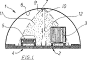
図1に自動車の2車線トンネル1の横断面を示す。トンネル断面の右側の走行車線2上にトラック車3を示し、対向車線4上に乗用車5を示す。
【0021】
トンネル天井6の中央領域の縦方向にセンサが等間隔になるよう超音波センサユニット7が配置される。各超音波センサユニット7にはそれぞれ2つの超音波センサ9,10が含まれ、それぞれは配属された円錐形の発射および受信領域11,12が隣接する状態で走行車線2と対向車線4に向かう。図1で明らかなように、発射および受信領域11,12は通過する自動車3、5を検知する。
【0022】
図2には、図1の走行車線2および対向車線4の概略的平面図を自動車3および5とともに示す。ほぼ円錐形の発射および受信領域11,12によって走行車線2および4上にほぼ円形の領域が投影される。超音波センサ9,10の配置は、発射および受信領域11,12が投影された円によって縦方向にも横方向にも明らかにほぼ隣接するように実施されるので、通過する自動車に関して走行車線2および4で隙間のない検知が可能となる。同様に互いに連続する超音波センサの発射および受信領域は多少重ねることができ、または多少間隔を空けることもできる。配置に際しては、自動車が検知できない場所が生じるような大きさに間隔を選択しないことが、または領域の重なりあるいは大き過ぎる領域のためにその間に存在するいくつかの自動車が場合によっては1台の自動車としてしか検出されないことにならないようにすることが重要である。
【0023】
図3にトンネル監視システムの機能概略図を走行車線2および4の概略平面図と共に示す。縦方向に10個の超音波センサユニット71から710が配置されるが、トンネルはさらに続くことがある。超音波ユニット75の領域で走行車線2に隣接して故障駐車場所13を設け、同様に超音波センサ75a,75b,および75cで監視される。走行車線2にはトラック車3が存在し、故障駐車場所には自動車14が停車している。
【0024】
トンネル監視管理室15に評価ユニット16が装備され、そこに超音波センサ9,10を有する超音波センサユニット7がそれぞれ、連続するバス17を介して接続される。評価ユニットは表示および記録装置を含むプロセス案内システム18に接続される。評価結果をさらに利用するため、概略的で典型的に2つの制御装置が設けられる。制御装置はトンネル入口の進入信号機19に関係し、この進入信号機19は、例えば走行車線2を自動車が停車している場合、または交通渋滞が確認された場合は「赤」に切り換る。さらに表示板20による制御がトンネルでなされ、例えば点滅する光の文字で交通案内の指示が与えられる。
【0025】
図4にはトンネル監視システムの典型的な回路図が示される。超音波センサユニット7の個々の超音波センサ9,10はアナログ−デジタル−変換器21に配属されて接続され、連続するバス17に接続される。連続するバス17は評価ユニット16に連絡する。この評価ユニット16は望ましい機能に応じて、また装備拡張に応じていくつかの、必要ならば互いに一体となった測定・評価ユニットを備える。特に、位置検出ユニットを介して、特定の発射・受信領域での自動車の位置に応じて自動車の位置を検出することができる。タイマーを介して走行時間測定、その結果、自動車の速度を決定する速度測定ユニットを使用した速度測定が可能となる。それに加えて、トンネルを通る特定の自動車の通過が追跡ユニットを使用して追跡され、トンネル入口からトンネル出口まで隙間のない通過追跡が可能となる。さらに自動車間の間隔測定、同様に走行方向認識および故障駐車場所の監視が実施可能となる。センサ信号の強さを評価することによって、評価ユニットを適当に構成する場合、自動車の高さと長さの探知することで自動車形式の認識も可能となる。前記の評価結果のすべてまたは一部は統計的な意味または制御介入または警告指示に関連づけることができる。
【0026】
評価装置16はここでは出力ユニットとして、典型的には視覚装置としての画面22に切り換えられ、これによって監視者はトンネル内の出来事をビジュアルに追跡することができる。さらに、例えばメモリや印刷などの公知の記録ユニットが可能となる。
【0027】
さらに、評価ユニット16の結果は制御ユニット23に導かれ、例えば交通案内、警告、安全確保などのために接続される表示装置が自動的に制御される。典型的にはランプ24は信号機および/または点滅ランプおよび/または光文字を意味する。さらにスピーカ25はサイレンおよび/または放送装置を概略的に指す。通風機26は換気、自動消火装置、閉鎖装置などのトンネルの安全装置が含まれる。
【図面の簡単な説明】
【図1】 トンネルの横断図を示す。
【図2】 トンネルの走行軌道の平面図を示す。
【図3】 トンネル監視装置の機能概略図を示す。
【図4】 図3によるトンネル装置の回路図を示す。[0001]
The present invention relates to a tunnel monitoring system for an automobile tunnel as defined in the premise of claim 1.
[0002]
A variety of embodiments of a tunnel monitoring system for an automobile tunnel are generally known.
For example, a tunnel monitoring system equipped with a fire alarm in the longitudinal direction of the tunnel is known. With this system, the possibility of fire in the tunnel, especially the investigation and location of the car causing the fire, is detected. The system further includes a control device that activates an automatic warning device, traffic guidance device or closure device in the event of a fire. Such a monitoring system is only suitable for recognizing fire-induced hazards.
[0003]
Another commonly known tunnel monitoring system is composed of a number of surveillance cameras that are spaced along the tunnel path. By displaying the progress detected by the camera on the screen of the tunnel monitoring management room and evaluating it by the supervisor, the tunnel portion assigned to each can be visually monitored. It is also known to monitor by turning such a monitoring camera. In this case, it is also possible to remotely control the turn from the tunnel monitoring management room.
[0004]
Such a tunnel monitoring system including a surveillance camera is expensive to procure and maintain. In particular, the function of a camera lens is limited by the generation of smoke when it becomes dirty or when a serious fire occurs. In addition, if a relatively wide tunnel area is detected by a surveillance camera with multiple cars if necessary and automatic image evaluation is difficult to perform, automatic recognition and evaluation of the inherent danger state in the system is not possible or simply limited. It is. Therefore, the use of the screen information of such a tunnel monitoring system is essentially a duty of the supervisor in the tunnel monitoring management room regarding the recognition of the dangerous state from the traveling speed and the inter-vehicle distance and the evaluation of the traffic density. In this way, the safety function essentially depends on the attention of the individual observer, so that the rapid recognition of the dangerous situation and the necessary quick action are not guaranteed.
[0005]
In the two known tunnel monitoring systems, the fire alarm and the monitoring camera can be used as a kind of position detection sensor of a car for a normal driving car and / or can be detected in a dangerous state. Disadvantages and weaknesses need to be removed at the time of purchase.
[0006]
An object of the present invention is to freely set up a tunnel monitoring system that can be manufactured inexpensively under good functions, does not require maintenance, and provides a means for automatically evaluating monitoring information that changes in large quantities. It is.
[0007]
This problem is solved by the features described in claim 1.
According to claim 1, the position detection sensor is implemented as an ultrasonic sensor, and the emission / reception area is directed to at least one traveling lane, and the vehicle passes through the emission / reception area of the ultrasonic sensor. If this is the case, an appropriate sensor signal is sent from this sensor together with a sensor recognition signal to the evaluation unit. The evaluation unit includes a travel time measurement unit in which travel time measurement is activated in response to the passage of an automobile within the launch / reception area of a specific ultrasonic sensor using sensor signals. Using the sensor signal that follows the ultrasonic sensor that follows the tunneling direction in which a car traveling in the launch and reception area is detected later, the travel time between at least these two ultrasonic sensors can be measured. In order to measure the travel time, the next ultrasonic sensor that follows directly or further spaced apart is considered for evaluation. The interval between the ultrasonic sensors that are taken into account for the measurement of the travel time is fixed in advance, so that the speed signal of a specific vehicle is immediately calculated by a speed measurement unit that is essentially composed of a multiplier and placed later. The
[0008]
The speed measurement is preferably performed for all types of automobiles traveling in the above-described tunnel, and when each automobile passes the first ultrasonic sensor, the measurement of the travel time is started, and the second assigned super Finish after passing the acoustic wave sensor. The evaluation unit detects such a speed signal for each car very quickly and stores it for another evaluation if necessary. In this case, the measurement length part is activated again for the subsequent car and a new travel time measurement. Since such measurement length portions are provided one after another in the route of the tunnel, each actual automobile is measured at each tunnel location. Thus, it is possible to determine information derived easily and quickly, such as the average speed traveled or the vehicle density.
[0009]
With this arrangement, the evaluation unit determines the running time threshold between two assigned ultrasonic sensors, so that a car that is running or stopped at a particularly low speed can be very quickly and automatically Are advantageously detected. Therefore, by further evaluating the sensor detection signal from the ultrasonic sensor in question, it is possible to automatically detect the position of a car that is stopped in the tunnel or traveling at a particularly low speed. Furthermore, the presence of a stationary car is indicated in the evaluation unit by the detection sensor signal not changing within a defined time.
[0010]
Due to a particularly preferred embodiment as claimed in
[0011]
The tunnel monitoring system according to the invention can be manufactured with relatively inexpensive and functionally reliable parts even in the preferred implementation for clearance-free monitoring. In particular, an ultrasonic sensor is a launcher unit that is relatively inexpensive, functionally reliable, hassle-free maintenance, and is reliable even under harsh operating conditions, such as coastal use. Such an ultrasonic sensor is more resistant to dirt and has an advantage that it can provide an effective signal for detecting the position of the automobile even when a fire occurs and smoke is generated. Furthermore, it is relatively easy to evaluate the sensor signals together with the respective sensor detection signals. The installation cost and operation cost are also relatively low.
[0012]
With the inventive tunnel monitoring system, it is possible to accurately detect the passage of vehicles based on individual vehicles using a tracking unit with a simple addition of an evaluation unit according to
[0013]
Furthermore, the evaluation unit described in
[0014]
In a particularly preferred embodiment, the sensor signal of the ultrasonic sensor as claimed in
[0015]
In another form according to claim 4, a unit counting unit capable of performing the counting of the automobile via the sensor signal can be easily incorporated into the evaluation unit.
The evaluation device of the one unit can be compactly integrated into the evaluation electronic device by a known method, and can be easily adapted to a specific built-in state if it has appropriate programmability.
[0016]
6. The feature according to
[0017]
The sensor signal must be digitized in the usual way for electronic evaluation, especially when evaluating the strength of the sensor signal. According to the sixth aspect of the present invention , an A / D converter corresponding to the purpose to be attached to the ultrasonic sensor is prepared, and the digitized signal is guided to the evaluation unit via the continuous bus system. In order to confirm from which ultrasonic sensor the determined sensor signal is received, it is necessary to send the sensor recognition signal together with the measurement value signal to the evaluation unit by a known method. For this reason, a two-guide system is used with simple equipment technology, and voltage supply of the ultrasonic sensor and the A / D converter can also be implemented via this. In particular, since only a voltage supply in the low voltage region is necessary, the danger to the safety of tunnel operation is further distant. Alternatively or additionally, signal transmission can be performed wirelessly from the ultrasonic sensor to the evaluation device. Therefore, the equipment expenditure is further reduced depending on the actual situation, and even when the cable may be destroyed in the event of a fire, a signal transmission without defects is reliably formed.
[0018]
Evaluation results are greatly automated using the tunnel monitoring system according to the invention, freeing the observer without the need for subjective evaluation, and also automated when dealing with specific evaluation results according to
[0019]
According to claim 8 , the tunnel monitoring system of the invention can be used for road and / or track tunnels. With a simple structure, simple and inexpensive equipment can be added to or combined with existing monitoring equipment for existing tunnels.
[0020]
The invention will be described in detail with reference to the drawings.
FIG. 1 shows a cross section of a two-lane tunnel 1 of an automobile. A
[0021]
The
[0022]
FIG. 2 shows a schematic plan view of the traveling
[0023]
FIG. 3 shows a functional schematic diagram of the tunnel monitoring system together with schematic plan views of the traveling
[0024]
The tunnel
[0025]
FIG. 4 shows a typical circuit diagram of a tunnel monitoring system. The individual
[0026]
The
[0027]
Further, the result of the
[Brief description of the drawings]
FIG. 1 shows a cross-sectional view of a tunnel.
FIG. 2 is a plan view of a traveling track of a tunnel.
FIG. 3 shows a functional schematic diagram of a tunnel monitoring device.
4 shows a circuit diagram of the tunnel device according to FIG. 3;
Claims (8)
自動車位置検出装置の構成要素として、少なくとも1つの走行車線(2,4)の縦方向にトンネルに分散して取り付けられた位置検出センサと、
位置検出センサのセンサ信号が供給される評価ユニット(16)と、
評価ユニット(16)の後に配置され、評価結果が表示できる出力ユニットと、
で構成されるトンネル監視システムにおいて、
位置検出センサは、少なくとも1つの走行車線(2,4)に発射・受信領域(11,12)が向けられた超音波センサ(7,9,10)であって、超音波センサ(7,9,10)の発射・受信領域(11,12)を自動車(3,5)が通過した場合、このセンサから適当なセンサ信号(16)が評価ユニットに送られるように形成され、
センサ信号を使用して特定の超音波センサ(7,9,10)の発射・受信領域(11,12)内の自動車(3,5)の通過に応じて走行時間測定が活性化され、さらに後に続くセンサ信号を使用してトンネルの走行方向の後に続く超音波センサの発射・受信領域で同一の自動車の遅れた通過に応じて、少なくともこれら2つの超音波センサ間の走行時間が測定できる走行時間測定ユニットが評価ユニット(16)に含まれ、
走行時間測定ユニットの後に、測定された走行時間と既知のセンサ間隔から自動車(3,5)の速度信号が算出可能な速度測定ユニットが配置され、
トンネル(1)の縦方向に相次いで続く超音波センサ(7,9,10)の発射・受信領域(11,12)が自動車検知領域で互いに境界を接し、自動車走行方向の縦間隔が普通の自動車の長さよりも短く、
自動車(3,5)がトンネルに進入するとき第1の超音波センサによって検知され、トンネル出口に至るまで後に続く超音波センサで次々と切り換えることによって通過が検知可能で、かつ制御可能である追跡ユニットが評価ユニット(1 6)に含まれ、
次への切り換えが中断された場合は、センサ認識信号と結合して、通過しなくなった超音波センサの位置に応じて自動車(3,5)の停止信号が出される
ことを特徴とするトンネル評価システム。A tunnel monitoring system for an automobile tunnel having at least one traveling lane,
As a component of the automobile position detection device, position detection sensors distributed in the tunnel in the longitudinal direction of at least one traveling lane (2, 4),
An evaluation unit (16) to which the sensor signal of the position detection sensor is supplied;
An output unit arranged after the evaluation unit (16) and capable of displaying the evaluation results;
In the tunnel monitoring system consisting of
The position detection sensor is an ultrasonic sensor (7, 9, 10) in which the emission / reception area (11, 12) is directed to at least one traveling lane (2, 4), and the ultrasonic sensor (7, 9). , 10) when the vehicle (3, 5) passes through the launch / receive area (11, 12), an appropriate sensor signal (16) is sent from this sensor to the evaluation unit,
The travel time measurement is activated in response to the passage of the car (3, 5) in the launch / reception area (11, 12) of the specific ultrasonic sensor (7, 9, 10) using the sensor signal, A travel that can measure at least the travel time between these two ultrasonic sensors in response to a delayed passage of the same vehicle in the launch / reception area of the ultrasonic sensors that follow the travel direction of the tunnel using subsequent sensor signals A time measurement unit is included in the evaluation unit (16),
After the travel time measurement unit, a speed measurement unit capable of calculating the speed signal of the automobile (3, 5) from the measured travel time and the known sensor interval is arranged,
The launch / reception areas (11, 12) of the ultrasonic sensors (7, 9, 10) successively following the longitudinal direction of the tunnel (1) are in contact with each other in the automobile detection area, and the vertical distance in the automobile traveling direction is normal. Shorter than the length of the car,
Tracking that is detected by the first ultrasonic sensor when the car (3, 5) enters the tunnel and can be detected and controlled by switching one after another by the ultrasonic sensor that continues to the tunnel exit. The unit is included in the evaluation unit ( 16)
When switching to the next is interrupted, it is combined with the sensor recognition signal, and a stop signal for the automobile (3, 5) is output according to the position of the ultrasonic sensor that has stopped passing. Tunnel evaluation system.
機能的に結合された一列の超音波センサ(7,9,10)が走行方向の走行車線(2,4)に、好ましくはそれぞれが1つの走行車線および故障駐車場所に配置されるA row of ultrasonic sensors (7, 9, 10) that are functionally coupled are arranged in the driving lane (2, 4) in the direction of travel, preferably each in one driving lane and a faulty parking location.
ことを特徴とする請求項1ないし4のいずれか1項に記載のトンネル評価システム。The tunnel evaluation system according to any one of claims 1 to 4, wherein
Applications Claiming Priority (2)
| Application Number | Priority Date | Filing Date | Title |
|---|---|---|---|
| EP00128758A EP1220181B1 (en) | 2000-12-30 | 2000-12-30 | Tunnel monitoring system in a tunnel |
| PCT/EP2001/015273 WO2002054368A1 (en) | 2000-12-30 | 2001-12-21 | Tunnel monitoring system in a vehicle tunnel |
Publications (3)
| Publication Number | Publication Date |
|---|---|
| JP2004517419A JP2004517419A (en) | 2004-06-10 |
| JP2004517419A5 JP2004517419A5 (en) | 2005-05-19 |
| JP3838975B2 true JP3838975B2 (en) | 2006-10-25 |
Family
ID=8170874
Family Applications (1)
| Application Number | Title | Priority Date | Filing Date |
|---|---|---|---|
| JP2002555391A Expired - Fee Related JP3838975B2 (en) | 2000-12-30 | 2001-12-21 | Tunnel monitoring system for automobile tunnel |
Country Status (7)
| Country | Link |
|---|---|
| US (1) | US6925377B2 (en) |
| EP (1) | EP1220181B1 (en) |
| JP (1) | JP3838975B2 (en) |
| AT (1) | ATE301861T1 (en) |
| DE (1) | DE50010935D1 (en) |
| NO (1) | NO20033006L (en) |
| WO (1) | WO2002054368A1 (en) |
Families Citing this family (52)
| Publication number | Priority date | Publication date | Assignee | Title |
|---|---|---|---|---|
| DE10243224B3 (en) * | 2002-08-23 | 2004-04-22 | Thyssenkrupp Hiserv Gmbh | Method and detection system for increasing the traffic safety of vehicles on a measuring section having at least one lane |
| EP2064097B1 (en) * | 2006-09-19 | 2011-05-18 | Ventech GmbH | Method for the automatic identification of a type of vehicle or type of tire on a test stand |
| US8762035B2 (en) | 2008-05-19 | 2014-06-24 | Waze Mobile Ltd. | System and method for realtime community information exchange |
| US8612136B2 (en) * | 2008-08-27 | 2013-12-17 | Waze Mobile Ltd. | System and method for road map creation |
| US8271057B2 (en) * | 2009-03-16 | 2012-09-18 | Waze Mobile Ltd. | Condition-based activation, shut-down and management of applications of mobile devices |
| EP2517189B1 (en) | 2009-12-22 | 2014-03-19 | Leddartech Inc. | Active 3d monitoring system for traffic detection |
| CN101799985B (en) * | 2010-03-18 | 2011-10-26 | 招商局重庆交通科研设计院有限公司 | Highway tunnel traffic identification method |
| ES2377613B1 (en) * | 2010-08-02 | 2013-02-01 | Universidad Carlos Iii De Madrid | METHOD FOR CHARACTERIZING THE ROLLED TRAFFIC. |
| US20120182160A1 (en) * | 2011-01-14 | 2012-07-19 | TCS International, Inc. | Directional Vehicle Sensor Matrix |
| US8908159B2 (en) | 2011-05-11 | 2014-12-09 | Leddartech Inc. | Multiple-field-of-view scannerless optical rangefinder in high ambient background light |
| US9378640B2 (en) | 2011-06-17 | 2016-06-28 | Leddartech Inc. | System and method for traffic side detection and characterization |
| DE102012011600B4 (en) * | 2012-02-21 | 2015-07-16 | Phoenix Contact Gmbh & Co. Kg | Method for controlling an escape route marker lighting |
| USRE48914E1 (en) | 2012-03-02 | 2022-02-01 | Leddartech Inc. | System and method for multipurpose traffic detection and characterization |
| ES2559827T3 (en) | 2012-08-22 | 2016-02-16 | Kapsch Trafficcom Ag | Procedures and devices for taking pictures of a vehicle that exceeds a speed |
| CN102930598B (en) * | 2012-10-08 | 2016-04-13 | 山东康威通信技术股份有限公司 | Three-dimensional model is used to locate and show the system and method for Tunnel testing equipment state |
| CN103309324A (en) * | 2013-06-05 | 2013-09-18 | 广州供电局有限公司 | Mobile tunnel environment inspection equipment |
| CN103309323B (en) * | 2013-06-05 | 2016-05-04 | 广州供电局有限公司 | Inspection device method for supervising and the system of tunnel environment |
| DE102013213583A1 (en) * | 2013-07-11 | 2015-01-15 | Bayerische Motoren Werke Aktiengesellschaft | System and method for assistance in a tunnel, in particular in a road tunnel |
| CN104123429A (en) * | 2014-08-15 | 2014-10-29 | 重庆巨蟹数码影像有限公司 | Synchronous control system for virtual simulation scene and actual scene |
| US10488492B2 (en) | 2014-09-09 | 2019-11-26 | Leddarttech Inc. | Discretization of detection zone |
| RU2606554C2 (en) * | 2015-02-24 | 2017-01-10 | Общество с ограниченной ответственностью "Техноисток" | System for controlling passage and movement in tunnel |
| CN104991488B (en) * | 2015-05-27 | 2018-01-30 | 华北电力大学(保定) | Intelligent robot inspection system for cable tunnel |
| JP2017037364A (en) * | 2015-08-06 | 2017-02-16 | オムロン株式会社 | Vehicle management system and vehicle management method |
| WO2017116325A1 (en) * | 2015-12-30 | 2017-07-06 | Hasan Kalyoncu Universitesi | Real time vehicle detection through highway tunnels |
| CN105679052A (en) * | 2016-04-01 | 2016-06-15 | 东南大学 | Multi-mode multilayer ground public transport signal priority coordination control method |
| CN106323231A (en) * | 2016-08-08 | 2017-01-11 | 爱德森(厦门)电子有限公司 | Acoustic monitoring device and method for settlement deformation of in-service rail transit tunnel surrounding rock |
| CN106200485A (en) * | 2016-08-10 | 2016-12-07 | 上海化学工业区公共管廊有限公司 | Public piping lane supervisory-controlled robot based on android system |
| CN106157522B (en) * | 2016-08-31 | 2018-08-21 | 招商局重庆交通科研设计院有限公司 | Vcehicular tunnel vehicle spontaneous combustion early warning system and method based on thermal sensation imaging |
| KR101936659B1 (en) * | 2016-12-01 | 2019-01-09 | 주식회사 스마트비전 | Apparatus and method for notifying traffic situation in tunnel |
| US10585185B2 (en) * | 2017-02-03 | 2020-03-10 | Rohde & Schwarz Gmbh & Co. Kg | Security scanning system with walk-through-gate |
| CN106952485B (en) * | 2017-05-09 | 2020-05-12 | 重庆幻凰科技有限公司 | Crossroad intelligent traffic light network control system capable of processing emergency |
| KR101974196B1 (en) * | 2017-05-15 | 2019-04-30 | 주식회사 에스티씨 | Traffic Information Displaying Syatem of Tunnel and Method thereof |
| CN107180533A (en) * | 2017-06-22 | 2017-09-19 | 北京中交华安科技有限公司 | Road method for early warning and device |
| JP6983632B2 (en) * | 2017-11-24 | 2021-12-17 | ホーチキ株式会社 | Traffic flow monitoring system in the tunnel |
| CN110271554B (en) * | 2018-03-13 | 2023-02-17 | 奥迪股份公司 | Driving assistance system and method for vehicle |
| CN109295872A (en) * | 2018-08-29 | 2019-02-01 | 安徽理工大学 | A kind of tunnel traffic management system and its implementation |
| CN109375549A (en) * | 2018-11-22 | 2019-02-22 | 上海塔盟网络科技有限公司 | A kind of subway tunnel internal box group's monitoring system based on Internet of Things and cloud computing |
| KR101996632B1 (en) * | 2018-11-23 | 2019-07-04 | 미성엠프로 주식회사 | Driver alarm device and system using communication facilities in road tunnel |
| CN109403229A (en) * | 2018-12-07 | 2019-03-01 | 山西路泽交通科技有限公司 | A kind of tunnel caution system |
| DE102018251771A1 (en) * | 2018-12-28 | 2020-07-02 | Robert Bosch Gmbh | Method for at least partially automated driving of a motor vehicle |
| CN109697473A (en) * | 2018-12-29 | 2019-04-30 | 中铁十九局集团第六工程有限公司 | A kind of detection method, computer installation and the computer readable storage medium of construction tunnel vehicle violation |
| CN110146930A (en) * | 2019-06-04 | 2019-08-20 | 成都希格玛光电科技有限公司 | Limit detection system and method are invaded in tunnel based on photodetection |
| CN110572792A (en) * | 2019-09-17 | 2019-12-13 | 广脉科技股份有限公司 | NB-loT-based railway tunnel monitoring system |
| JP7244398B2 (en) * | 2019-10-14 | 2023-03-22 | 株式会社デンソー | Moving object detection device |
| GB2590730B (en) * | 2020-01-03 | 2022-08-17 | Valerann Ltd | Automatically tracking a trajectory of a vehicle |
| US11769412B2 (en) * | 2020-06-10 | 2023-09-26 | Hyundai Mobis Co., Ltd. | Rear side warning system and method for vehicle |
| CN113310528B (en) * | 2021-06-16 | 2022-10-04 | 深圳防灾减灾技术研究院 | Real-time tunnel structure health monitoring method based on multivariate sensing data |
| CN114333303B (en) * | 2021-12-20 | 2022-12-16 | 武汉微创光电股份有限公司 | Highway tunnel monitoring data fusion processing system |
| CN115773473A (en) * | 2022-04-29 | 2023-03-10 | 重庆大学 | Monitoring system and monitoring method for natural gas leakage in tunnel |
| CN115100862B (en) * | 2022-06-23 | 2023-03-31 | 北京交科公路勘察设计研究院有限公司 | Road tunnel intelligent light early warning system and method based on multi-source data perception |
| CN115601963B (en) * | 2022-09-28 | 2024-01-30 | 广州市恒盛建设工程有限公司 | Construction method for active intelligent induction spike linkage monitoring control system in ultra-long tunnel |
| CN115981219B (en) * | 2023-03-21 | 2023-06-30 | 山东博安智能科技股份有限公司 | Intelligent monitoring system for high-speed tunnel |
Family Cites Families (12)
| Publication number | Priority date | Publication date | Assignee | Title |
|---|---|---|---|---|
| US3668625A (en) * | 1970-09-21 | 1972-06-06 | David Wolf | Monitoring system |
| US4789941A (en) * | 1986-07-18 | 1988-12-06 | Bennett Nunberg | Computerized vehicle classification system |
| GB2231753A (en) * | 1989-05-05 | 1990-11-21 | Golden River Ltd | Traffic incident monitoring with vido cameras |
| US5173692A (en) * | 1990-08-13 | 1992-12-22 | Ai Computer Services, Inc. | System and method of vehicle detection |
| US5305390A (en) * | 1991-01-11 | 1994-04-19 | Datatec Industries Inc. | Person and object recognition system |
| US5528234A (en) * | 1994-02-01 | 1996-06-18 | Mani; Siva A. | Traffic monitoring system for determining vehicle dimensions, speed, and class |
| US5778332A (en) * | 1995-11-17 | 1998-07-07 | J-Squared, Llc | Electronic nervous system for a roadway and method |
| JPH09282581A (en) * | 1996-04-17 | 1997-10-31 | Hitachi Ltd | Method and device for detecting vehicle accident inside tunnel |
| JPH1088996A (en) * | 1996-09-12 | 1998-04-07 | Shinko Electric Co Ltd | Fire robot for inside of tunnel |
| CA2656132C (en) * | 1998-05-15 | 2012-10-02 | International Road Dynamics Inc. | Method for detecting and signalling truck presence |
| DE19929645C2 (en) * | 1999-06-28 | 2001-07-12 | Gerhaher Christiane | Road traffic control system for dangerous routes, in particular tunnels, and light signaling devices |
| JP2001103451A (en) * | 1999-09-29 | 2001-04-13 | Toshiba Corp | System and method for image monitoring |
-
2000
- 2000-12-30 EP EP00128758A patent/EP1220181B1/en not_active Expired - Lifetime
- 2000-12-30 AT AT00128758T patent/ATE301861T1/en not_active IP Right Cessation
- 2000-12-30 DE DE50010935T patent/DE50010935D1/en not_active Expired - Fee Related
-
2001
- 2001-12-21 US US10/451,935 patent/US6925377B2/en not_active Expired - Fee Related
- 2001-12-21 JP JP2002555391A patent/JP3838975B2/en not_active Expired - Fee Related
- 2001-12-21 WO PCT/EP2001/015273 patent/WO2002054368A1/en active Application Filing
-
2003
- 2003-06-30 NO NO20033006A patent/NO20033006L/en not_active Application Discontinuation
Also Published As
| Publication number | Publication date |
|---|---|
| WO2002054368A1 (en) | 2002-07-11 |
| NO20033006D0 (en) | 2003-06-30 |
| ATE301861T1 (en) | 2005-08-15 |
| US6925377B2 (en) | 2005-08-02 |
| EP1220181B1 (en) | 2005-08-10 |
| NO20033006L (en) | 2003-06-30 |
| US20040059503A1 (en) | 2004-03-25 |
| JP2004517419A (en) | 2004-06-10 |
| DE50010935D1 (en) | 2005-09-15 |
| EP1220181A1 (en) | 2002-07-03 |
Similar Documents
| Publication | Publication Date | Title |
|---|---|---|
| JP3838975B2 (en) | Tunnel monitoring system for automobile tunnel | |
| US5864304A (en) | Wireless railroad grade crossing warning system | |
| CN107953830B (en) | Large bus blind area detection alarm system and detection alarm method thereof | |
| US6688561B2 (en) | Remote monitoring of grade crossing warning equipment | |
| JP2004517419A5 (en) | ||
| JP3342017B2 (en) | Fault detection system | |
| EP3328707A2 (en) | System for securing of safety of railroad crossing against vehicle entry during warning signaling | |
| CN105390027B (en) | A kind of road safety monitoring and early warning device and method | |
| KR101682061B1 (en) | The road alarm system and control method thereof | |
| CN111369828B (en) | Safety early warning system and method for vehicle turning blind area | |
| WO2014072730A1 (en) | Road safety apparatus | |
| CN111717241A (en) | Crossing warning system and crossing warning control method | |
| US20060180712A1 (en) | Advance warning system for railroad crossing | |
| KR20050062889A (en) | Train emergency control system and method using unexpected accident image detector | |
| KR102216785B1 (en) | Driving control method for autonomous vehicle | |
| KR102246833B1 (en) | Vehicle Congestion and Road Situation Notification System | |
| JP2011090513A (en) | System and method of detecting fallen object | |
| KR101128978B1 (en) | Intelligence System for Accident Prevention at Railway Level Crossing and Train Brake Method | |
| EP1168276A1 (en) | Traffic control system for signalling timely any obstruction on the road | |
| JPH11120457A (en) | Tunnel disaster preventing system | |
| KR101819420B1 (en) | Highway Shelter Entry and Exit Notification System | |
| CN113734207B (en) | Vehicle safety protection system and method and vehicle | |
| JPH0245264A (en) | System for monitoring situation in running way | |
| JP3914944B2 (en) | Crossing road information communication device | |
| KR200345401Y1 (en) | Train emergency control system using unexpected accident image detector |
Legal Events
| Date | Code | Title | Description |
|---|---|---|---|
| A621 | Written request for application examination |
Free format text: JAPANESE INTERMEDIATE CODE: A621 Effective date: 20041020 |
|
| TRDD | Decision of grant or rejection written | ||
| A01 | Written decision to grant a patent or to grant a registration (utility model) |
Free format text: JAPANESE INTERMEDIATE CODE: A01 Effective date: 20060704 |
|
| A61 | First payment of annual fees (during grant procedure) |
Free format text: JAPANESE INTERMEDIATE CODE: A61 Effective date: 20060801 |
|
| R150 | Certificate of patent or registration of utility model |
Free format text: JAPANESE INTERMEDIATE CODE: R150 |
|
| LAPS | Cancellation because of no payment of annual fees |