CN115773473A - Monitoring system and monitoring method for natural gas leakage in tunnel - Google Patents
Monitoring system and monitoring method for natural gas leakage in tunnel Download PDFInfo
- Publication number
- CN115773473A CN115773473A CN202211245123.2A CN202211245123A CN115773473A CN 115773473 A CN115773473 A CN 115773473A CN 202211245123 A CN202211245123 A CN 202211245123A CN 115773473 A CN115773473 A CN 115773473A
- Authority
- CN
- China
- Prior art keywords
- leakage
- source
- tunnel
- gas
- leakage source
- Prior art date
- Legal status (The legal status is an assumption and is not a legal conclusion. Google has not performed a legal analysis and makes no representation as to the accuracy of the status listed.)
- Pending
Links
- VNWKTOKETHGBQD-UHFFFAOYSA-N methane Chemical compound C VNWKTOKETHGBQD-UHFFFAOYSA-N 0.000 title claims abstract description 150
- 238000012544 monitoring process Methods 0.000 title claims abstract description 52
- 238000000034 method Methods 0.000 title claims abstract description 41
- 239000003345 natural gas Substances 0.000 title claims abstract description 28
- 238000004364 calculation method Methods 0.000 claims abstract description 37
- 230000003287 optical effect Effects 0.000 claims abstract description 11
- 239000007789 gas Substances 0.000 claims description 72
- 238000009826 distribution Methods 0.000 claims description 49
- 238000004880 explosion Methods 0.000 claims description 24
- 230000003068 static effect Effects 0.000 claims description 16
- 238000009792 diffusion process Methods 0.000 claims description 13
- 238000002474 experimental method Methods 0.000 claims description 6
- 238000004088 simulation Methods 0.000 claims description 6
- 238000005315 distribution function Methods 0.000 claims description 5
- 238000013507 mapping Methods 0.000 claims description 3
- 238000009827 uniform distribution Methods 0.000 claims description 3
- 238000010586 diagram Methods 0.000 description 6
- 230000006870 function Effects 0.000 description 5
- 230000004044 response Effects 0.000 description 4
- 230000006378 damage Effects 0.000 description 3
- 239000002360 explosive Substances 0.000 description 3
- 208000027418 Wounds and injury Diseases 0.000 description 2
- 238000001514 detection method Methods 0.000 description 2
- 230000002708 enhancing effect Effects 0.000 description 2
- 208000014674 injury Diseases 0.000 description 2
- 239000003949 liquefied natural gas Substances 0.000 description 2
- 238000010801 machine learning Methods 0.000 description 2
- 238000005259 measurement Methods 0.000 description 2
- 238000004904 shortening Methods 0.000 description 2
- 206010003497 Asphyxia Diseases 0.000 description 1
- 208000001034 Frostbite Diseases 0.000 description 1
- 238000013461 design Methods 0.000 description 1
- 230000000694 effects Effects 0.000 description 1
- 239000000446 fuel Substances 0.000 description 1
- 239000000203 mixture Substances 0.000 description 1
- 239000000779 smoke Substances 0.000 description 1
- 238000000547 structure data Methods 0.000 description 1
Images


Abstract
The invention discloses a system and a method for monitoring natural gas leakage in a tunnel, which comprises a sensor, an optical cable, a host, an alarm device and a display device, wherein the sensor is connected with the host through the optical cable, the host is respectively connected with the alarm device and the display device, the host comprises a control unit, a leakage source positioning calculation unit, a leakage source leakage rate inversion calculation unit and an early warning decision unit, the leakage source positioning calculation unit positions the position of a leakage source according to methane concentration data, the leakage source leakage rate inversion calculation unit calculates the leakage rate of the leakage source according to the methane concentration data, the early warning decision unit controls the starting and stopping of the alarm device according to the methane concentration data, and the leakage source positioning result and the leakage source leakage rate calculation result are both output to the display device. The invention realizes high automation, is automatically detected by the sensor, and has high efficiency through real-time early warning and judgment of the host. The links such as information acquisition, transportation, storage are all carried out through monitoring and early warning system, and the human factor influence is little.
Description
Technical Field
The invention relates to a natural gas leakage monitoring system in a tunnel and a monitoring method of the natural gas leakage monitoring system in the tunnel.
Background
Compressed natural gas and liquefied natural gas tank car road transportation is one of the common transportation modes of natural gas, and the compressed natural gas and the liquefied natural gas are also power fuels of many vehicles. In the process of running through a tunnel, if leakage is caused by accidents such as high temperature (fire disasters), impact, pipe fitting falling and the like, flammable and explosive gas clouds are formed in the space of the tunnel and can cause anoxic suffocation and frostbite of people, dangerous accidents such as steam cloud explosion and the like can occur in the tunnel when the flammable and explosive gas clouds are formed and meet an ignition source, and the generated high-temperature smoke and overpressure can cause serious damage to people and property.
However, in the current 'design code of highway tunnels' in China, the monitoring of the gas concentration is only required to be carried out through the tunnels of gas strata, and the monitoring of flammable and explosive gases in the highway tunnels is not universally required, so that the arrangement of a methane monitoring system in the tunnels is very necessary.
Disclosure of Invention
The invention aims to provide a natural gas leakage monitoring system in a tunnel, which can effectively monitor and early warn natural gas in the tunnel, position accident sites and improve accident handling efficiency.
The first object of the invention is achieved by the following technical measures: the utility model provides a natural gas leakage monitoring system in tunnel, its characterized in that, it is including sensor, optical cable, host computer, alarm device and the display device who is used for gathering methane concentration, the sensor is a plurality of and is connected with the host computer through the optical cable, the host computer links to each other with alarm device, display device respectively, the host computer includes the control unit, leaks source location calculating unit, leaks source leakage rate back calculation unit and early warning decision-making unit who is connected with it respectively, wherein, leak source location calculating unit fixes a position the source position according to methane concentration data, leak source leakage rate back calculation unit calculates leaking the source leakage rate according to methane concentration data, early warning decision-making unit opens and stops according to methane concentration data control alarm device, leaks source location result and leaks source leakage rate calculation result and all exports to display device on.
The invention can realize high automation, automatic detection by the methane sensor and real-time early warning judgment by the host, and has high working efficiency. All links such as information acquisition, transportation, storage are carried out through monitoring and early warning system, need not artifical the participation, and the human factor influence is little. The method can realize the early warning of natural gas leakage in the tunnel and the calculation of the position and the intensity of the leakage source, simultaneously utilizes the monitored methane concentration data to carry out the early warning of the natural gas leakage, and carries out inversion on the intensity and the position of the leakage source, thereby shortening the response time of accident disposal, improving the probability of early warning of the occurrence of the leakage accident and enhancing the pertinence and the effectiveness of accident response measures. The monitored methane concentration data is combined with a machine learning method to carry out inversion on the natural gas leakage source and the leakage intensity, position and leakage intensity information can be provided for accident rescue and accident disposal, in addition, reference can also be provided for accident disposal measures, and a suitable disaster relief scheme is provided by combining calculated leakage source information.
The sensors are distributed on the inner wall of the tunnel at intervals along the length direction of the tunnel, and the distance between two adjacent sensors is calculated through the following steps:
s1, carrying out numerical simulation on the gas leakage diffusion process in the tunnel under different gas cloud volumes by using gas leakage diffusion numerical simulation software to obtain the gas cloud distribution form of the leaked gas in the tunnel;
s2, carrying out a numerical experiment on the gas explosion consequence by using gas explosion consequence calculation software to quantify the maximum explosion overpressure value generated by gas explosion in the tunnel under different leakage time lengths;
s3, mapping the maximum explosion overpressure values under different gas cloud volumes to a gas cloud volume range corresponding to the maximum explosion overpressure of 20KPa (light injury of human body);
and S4, taking the distance of the combustible gas cloud in the length direction of the tunnel as the maximum distance between adjacent sensors.
The second purpose of the invention is to provide a monitoring method of the natural gas leakage monitoring system in the tunnel.
The second object of the invention is achieved by the following technical measures: the monitoring method of the natural gas leakage monitoring system in the tunnel is characterized by comprising the following steps:
s1, monitoring methane concentration data by a sensor, and transmitting the methane concentration data to a host through an optical cable;
s2, the host receives the methane concentration data, and the early warning decision unit judges the methane concentration data to obtain a judgment result;
s3, the alarm device responds to the judgment result;
and S4, a leakage source leakage rate inversion calculation unit in the host machine calculates the leakage rate of the leakage source, a leakage source positioning calculation unit calculates the leakage position of the leakage source, and the calculation result of the leakage rate of the leakage source and the positioning result of the leakage source are output to a display device.
In step S2, the basis of the determination by the early warning decision unit is:

in the formula: c i -the methane concentration measured by the ith methane gas detector; LEL-lower explosion limit of methane gas, 5%.
In step S4, the calculating of the leakage rate and the leakage position of the leakage source specifically includes:
(1) Calculating the forward distribution of the flow field when the leakage source is in a static state, and obtaining concentration parameters of the leakage source at different moments in the gas leakage process at the positions of monitoring points when the leakage source is in the static state;
(2) Assuming that a leakage source in a tunnel is always in a uniform motion state from the beginning of entering the tunnel to the end of exiting the tunnel, calculating forward distribution of a flow field when the leakage source is in the uniform motion state, and obtaining concentration parameters of different moments in the gas leakage process at each monitoring point position when the leakage source is in the uniform motion state;
(3) The prior distribution function of the leakage source intensity and the leakage position is assumed to be a uniform distribution function in a certain range;
(4) Calculating a likelihood function of observation concentration distribution under the condition that the prior distribution of the intensity of the leakage source is established according to the observation data of each sensor;
(5) Calculating the posterior distribution approximate solution of the source item leakage rate parameter by using Bayesian theorem in combination with the prior distribution, the predicted concentration and the observation data;
(6) And calculating the values of the leakage rate and the leakage position of the leakage source as corresponding values when the posterior distribution probability is maximum, and obtaining the inversion result of the leakage rate and the leakage position when the leakage source is in a static state and the inversion result of the leakage rate when the leakage source is in a constant-speed motion state.
The invention discloses a method for calculating the forward distribution of a flow field when a leakage source is in a static state, which comprises the following steps:
(1) adopting a CFD three-dimensional numerical simulation method at a tunnel section within 100m in the longitudinal direction away from the leakage source to respectively solve the tunnel gas leakage concentration distribution at different leakage source strengths and leakage source positions;
(2) adopting a simplified one-dimensional gas diffusion model in a tunnel section which is away from the leakage source by 100m in the longitudinal direction, and respectively solving the tunnel gas leakage concentration distribution at different leakage source intensities and leakage source positions;
(3) and when the leakage source is in a static state, the concentration parameters at different moments in the gas leakage process at the positions of the monitoring points are calculated by the forward model.
The invention discloses a method for calculating the forward distribution of a flow field when a leakage source is in a uniform motion state, which comprises the following steps:
(1) the leakage concentration field continuously released in the tunnel is regarded as a continuous instantaneous point source in a range along the longitudinal length of the tunnel under a certain time sequence, and when the length of the tunnel is L, the intensity of the leakage source continuously released in the tunnel is q 0 Continuously released leakage sources are regarded as point sources of instant release at certain intervals delta x, and the driving speed of the tunnel is designed to be u 0 Calculating the leakage of each point source as
(2) Respectively solving tunnel interior by adopting one-dimensional gas diffusion model Point sources at time intervals u 0 Longitudinal concentration distribution of the flow field after Δ x is released in sequence;
(3) and obtaining concentration parameters of the leakage source at different moments in the gas leakage process at the positions of the monitoring points calculated by the forward model when the leakage source is in a uniform motion state.
The prior distribution function of the leakage source intensity and the leakage position is as follows:

in the formula:
p(Y k ) -a prior distribution of leak source intensities;
W max -estimating an upper value of the parameter;
W min -estimating a lower value of the parameter.
The calculation formula of the step (4) of the invention is as follows:

wherein C β A measured concentration value of the sensor is represented, representing the sensor values, σ, calculated using a forward model f·k Representing the standard deviation, sigma, of the concentration data calculated by the forward model β·k Indicating the standard deviation of the concentration data measured with the sensor.
Compared with the prior art, the invention has the following remarkable effects:
(1) The invention can realize high automation, automatic detection by the methane sensor and real-time early warning judgment by the host, and has high working efficiency. All links such as information acquisition, transportation, storage are all gone on through monitoring and early warning system, need not artifical the participation, and the human factor influence is little.
(2) The method can realize the early warning of natural gas leakage in the tunnel and the calculation of the position and the intensity of the leakage source, simultaneously utilizes the monitored methane concentration data to carry out the early warning of the natural gas leakage, and carries out inversion on the intensity and the position of the leakage source, thereby shortening the response time of accident disposal, improving the probability of early warning of the occurrence of the leakage accident and enhancing the pertinence and the effectiveness of accident response measures.
(3) The method utilizes the monitored methane concentration data to carry out inversion on the natural gas leakage source and the leakage intensity by combining a machine learning method, can provide position and leakage intensity information for accident rescue and accident disposal, and can also provide reference for accident disposal measures and provide a suitable disaster relief scheme by combining calculated leakage source information.
Drawings
The invention is described in further detail below with reference to the figures and the specific embodiments.
FIG. 1 is a schematic diagram of the composition structure of the natural gas leakage monitoring system in the tunnel according to the present invention;
FIG. 2 is a block flow diagram of a monitoring method of the present invention;
FIG. 3 is a block flow diagram of leak location and leak rate inversion according to the present invention;
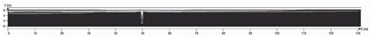
FIG. 4 is a schematic view of the gas cloud concentration distribution obtained by numerical calculation according to the present invention;
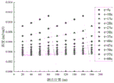
FIG. 5 is a schematic diagram of the calculated result of the concentration of each measuring point obtained by calculating the leakage source moving at a constant speed through the forward model;
FIG. 6 is a schematic diagram of the concentration calculation results of the measuring points obtained by calculating the leakage source in uniform motion through three-dimensional simulation according to the present invention;
FIG. 7 is a schematic illustration of the inversion results of the position of a leakage source of the present invention with the leakage source at rest;
FIG. 8 is a schematic diagram of the inversion result of the intensity of the leakage source in a state of uniform motion.
Detailed Description
As shown in fig. 1, the invention relates to a monitoring system for natural gas leakage in a tunnel, which comprises sensors 1 for collecting methane concentration, an optical cable 2, a host 3, alarm devices 4 and a display device (not shown in the figure), wherein the sensors 1 are distributed on the inner wall of the tunnel at intervals along the length direction of the tunnel, the host 3 and the alarm devices 4 are installed in a cabinet 5, the sensors 1 are a plurality of and are connected with the host 3 through the optical cable 2, the host 3 is respectively connected with the alarm devices 4 and the display device, the host 3 comprises a control unit, a leakage source positioning calculation unit, a leakage source leakage rate inversion calculation unit and an early warning decision unit, the leakage source positioning calculation unit positions the position of a leakage source according to the methane concentration data, the leakage source leakage rate inversion calculation unit calculates the leakage rate of the leakage source according to the methane concentration data, the early warning decision unit controls the starting and stopping of the alarm devices according to the methane concentration data, and both the leakage source positioning result and the leakage rate calculation result are output to the display device.
As shown in fig. 2, the system for monitoring natural gas leakage in a tunnel of the present invention is installed, specifically:
1. determining a sensor arrangement pitch in the longitudinal direction:
(1) Modeling is carried out according to tunnel structure data, the length (X), the width (Y) and the height (Z) of a highway tunnel numerical experiment model in the embodiment are respectively 200m multiplied by 6m, and the gas leakage diffusion process of the compressed natural gas in the tunnel is numerically simulated by using gas leakage diffusion numerical simulation software to obtain the distribution form of the gas cloud of the leaked gas in the tunnel.
(2) According to the gas cloud concentration distribution at different moments obtained by simulating the natural gas leakage diffusion numerical value, performing a numerical experiment on the gas explosion consequence by using gas explosion consequence calculation software, wherein the calculation result is shown in fig. 4, and performing a numerical experiment on the gas explosion consequence by using the gas explosion consequence calculation software so as to quantify the maximum explosion overpressure value generated by gas explosion in the tunnel under different leakage time lengths.
(3) And mapping to the gas cloud volume range corresponding to the maximum explosion overpressure of 20KPa (light injury of human body) according to the explosion maximum overpressure values under different gas cloud volumes.
(4) The distance of the combustible gas cloud in the tunnel length direction at this time is taken as the arrangement distance of the methane concentration sensors, and if the arrangement distance of the methane concentration sensors obtained in this case is 20m, the total number of the methane concentration sensors in the model of this embodiment is 9.
2. And arranging the monitoring system according to the longitudinal arrangement distance of the sensors, and monitoring data in real time.
A monitoring method of the natural gas leakage monitoring system in the tunnel specifically comprises the following steps:
s1, when methane gas generated by tank car leakage diffuses in a tunnel, a sensor monitors real-time methane concentration data and transmits the methane concentration data to a host through an optical cable;
s2, the host receives the methane concentration data, and the early warning decision unit judges the methane concentration data to obtain a judgment result; the judgment basis of the early warning decision unit is as follows:

in the formula: c i -the methane concentration measured by the ith methane gas detector; LEL-lower explosion limit of methane gas, 5%.
S3, the alarm device responds to the judgment result;
and S4, calculating the leakage rate of the leakage source by a leakage source leakage rate inversion calculation unit in the host, calculating the leakage position of the leakage source by a leakage source positioning calculation unit, and outputting the calculation result of the leakage rate of the leakage source and the positioning result of the leakage source to a display device.
As shown in fig. 3, calculating the leakage rate and the leakage position of the leakage source specifically includes:
(1) Calculating the forward distribution of the flow field when the leakage source is in a static state, and obtaining concentration parameters of the leakage source at different moments in the gas leakage process at the positions of monitoring points when the leakage source is in the static state;
in this embodiment, when the calculated leakage source intensities are 0.1kg/s, 0.2kg/s, 0.3kg/s, 0.4kg/s, 0.5kg/s, 0.6kg/s, 0.7kg/s, 0.8kg/s, 0.9kg/s, and 1.0kg/s, the leakage positions are the forward distribution of the static leakage source flow field every 5m in the tunnel space.
(1) Adopting a CFD three-dimensional numerical simulation method at a tunnel section within 100m in the longitudinal direction away from the leakage source to respectively solve the tunnel gas leakage concentration distribution at different leakage source strengths and leakage source positions;
(2) adopting a simplified one-dimensional gas diffusion model in a tunnel section which is 100m away from a leakage source along the longitudinal direction, calculating an equation by adopting a time front term and central difference method, and programming to solve tunnel gas leakage concentration distribution at different leakage source strengths and leakage source positions;
(3) and extracting concentration parameters in the gas leakage process at the positions of the monitoring points calculated by the forward model when the leakage source is in a static state, wherein data is recorded every 20s at each measuring point, and the leakage duration time is 600s.
(2) Assuming that a leakage source in a tunnel is always in a uniform motion state from the beginning of entering the tunnel to the end of exiting the tunnel, calculating forward distribution of a flow field when the leakage source is in the uniform motion state, and obtaining concentration parameters of different moments in the gas leakage process at each monitoring point position when the leakage source is in the uniform motion state;
in the embodiment, when the intensities of the leakage sources in the tunnel are calculated to be 0.1kg/s, 0.2kg/s, 0.3kg/s, 0.4kg/s, 0.5kg/s, 0.6kg/s, 0.7kg/s, 0.8kg/s, 0.9kg/s and 1.0kg/s respectively, the flow field forward distribution when the leakage sources are in the motion state is calculated on the assumption that the leakage sources are in the uniform motion state all the time from the tunnel entrance to the tunnel exit.
(1) Regarding a leakage concentration field continuously released in a tunnel as a continuous instantaneous point source in a certain time sequence within a range along the longitudinal length of the tunnel, regarding the continuously released leakage source as a point source at intervals of a certain distance of 5m when the length of the tunnel is 200m and the intensity of the continuously released leakage source in the tunnel is 0.1kg/s, and calculating the leakage amount of each point source as 60km/h when a travelling crane is in the tunnel
(2) And respectively solving the longitudinal concentration distribution of the flow field after the 39 point sources in the tunnel are released by adopting a one-dimensional gas diffusion model, wherein the leakage duration is 60s, and every 1s records one datum, and the calculation result is shown in figure 5 when the leakage source intensity is 0.9 kg/s.
(3) And obtaining concentration parameters of the leakage source at different moments in the gas leakage process at the positions of the monitoring points calculated by the forward model when the leakage source is in a uniform motion state.
And obtaining the concentration distribution of each measuring point at each moment by adopting a three-dimensional numerical experiment method, and taking the concentration distribution as a sensor measurement concentration value of inversion calculation. For a static leakage source in the tunnel, the leakage concentration in the tunnel is 0.26kg/s, and the position of the leakage source is 50m; for the leakage source in the moving state in the tunnel, the leakage concentration is 0.77kg/s, and the calculation result is shown in FIG. 6.
(3) The prior distribution function of the leakage source intensity and the leakage position is assumed to be a uniform distribution function in a certain range;
the calculation formula is as follows:

in the formula:
p(Y k ) -a prior distribution of leak source intensities;
W max -estimating an upper value of the parameter;
W min -estimating a lower value of the parameter.
When the leakage source is in static state, the intensity prior distribution of the leakage source obeys U0, 1, and the position prior distribution of the leakage source obeys U0, 200; when the leakage source is in a uniform motion state, the intensity prior distribution of the leakage source follows U [0,1].
(4) Calculating a likelihood function of the observation concentration distribution under the condition that the prior distribution of the intensity of the leakage source is satisfied according to the observation data of each sensor, wherein the calculation formula is as follows:

namely:

wherein Indicating the jth measurement of the ith sensorThe value of the intensity of the light beam is,
 the method is characterized in that j-th measured concentration value of each sensor calculated by using a forward model is shown, sigma is the standard deviation between the calculated concentration and the measured concentration of the forward model, the error and the measured concentration are set to be the same magnitude, and the standard deviation is assumed to be the same as the measured concentration.
(5) Calculating the posterior distribution approximate solution of the source item leakage rate parameter by using Bayes theorem in combination with prior distribution, predicted concentration and observation data, and obtaining p (Y) k |β)=(p(Y k )p(β|Y k ) /(p (β)), wherein p (Y) k ) For a prior distribution, p (β | Y) k ) Is a likelihood function.
(6) And performing curve fitting according to the probability values of the calculated leakage source intensity and position, and taking the maximum probability value of the fitted curve as an inversion result. For a stationary state leakage source, the inversion result of the position of the leakage source is shown in fig. 7, the inversion result of the position of the leakage source is 39.95m, the error is 10.05m, the inversion result of the intensity of the leakage source is 0.17kg/s, and the error is 0.07kg/s; for the leakage source in a uniform motion state, the intensity of the leakage source corresponding to the probability maximum value obtained after fitting is 0.706kg/s, the error is 0.064kg/s, and the inversion result of the intensity of the leakage source is shown in fig. 8.
The embodiments of the present invention are not limited thereto, and according to the above-described contents of the present invention, the present invention can be modified, substituted or changed in various other forms according to the general technical knowledge and the conventional means in the field, which fall within the scope of the present invention.
Claims (9)
1. The utility model provides a natural gas leakage monitoring system in tunnel which characterized in that: it is including sensor, optical cable, host computer, alarm device and display device that is used for gathering methane concentration, the sensor is a plurality of and is connected with the host computer through the optical cable, the host computer links to each other with alarm device, display device respectively, the host computer includes the control unit, leaks source location calculating unit, leaks source leakage rate back calculation unit and early warning decision-making unit who is connected with it respectively, wherein, leak source location calculating unit and fix a position the source position according to methane concentration data, leak source leakage rate back calculation unit and calculate leaking source leakage rate according to methane concentration data, early warning decision-making unit opens and stops according to methane concentration data control alarm device, leaks source location result and leaks source leakage rate calculation result and all exports to display device.
2. The in-tunnel natural gas leakage monitoring system according to claim 1, characterized in that: the sensors are distributed on the inner wall of the tunnel at intervals along the length direction of the tunnel, and the distance between every two adjacent sensors is calculated through the following steps:
s1, carrying out numerical simulation on the gas leakage diffusion process in the tunnel under different gas cloud volumes by using gas leakage diffusion numerical simulation software to obtain the distribution form of gas cloud of leaked gas in the tunnel;
s2, carrying out a numerical experiment on the gas explosion consequence by using gas explosion consequence calculation software to quantify the maximum explosion overpressure value generated by gas explosion in the tunnel under different leakage time lengths;
s3, mapping to a gas cloud volume range corresponding to the maximum explosion overpressure of 20KPa according to the maximum explosion overpressure values under different gas cloud volumes;
and S4, taking the distance of the combustible gas cloud in the length direction of the tunnel as the maximum distance between adjacent sensors.
3. The monitoring method of the natural gas leakage monitoring system in the tunnel according to claim 1, characterized by comprising the following steps:
s1, monitoring methane concentration data by a sensor, and transmitting the methane concentration data to a host through an optical cable;
s2, the host receives the methane concentration data, and the early warning decision unit judges the methane concentration data to obtain a judgment result;
s3, the alarm device responds to the judgment result;
and S4, calculating the leakage rate of the leakage source by a leakage source leakage rate inversion calculation unit in the host, calculating the leakage position of the leakage source by a leakage source positioning calculation unit, and outputting the calculation result of the leakage rate of the leakage source and the positioning result of the leakage source to a display device.
4. The monitoring method according to claim 3, characterized in that: in step S2, the basis for the early warning decision unit is:

in the formula: c i -the methane concentration measured by the ith methane gas detector; LEL-lower explosion limit of methane gas, 5%.
5. The monitoring method according to claim 4, wherein: in step S4, calculating the leakage rate and the leakage position of the leakage source specifically includes:
(1) Calculating the forward distribution of a flow field when the leakage source is in a static state to obtain concentration parameters of different moments in the gas leakage process at each monitoring point position when the leakage source is in the static state;
(2) Assuming that a leakage source in a tunnel is always in a uniform motion state from the beginning of entering the tunnel to the end of exiting the tunnel, calculating forward distribution of a flow field when the leakage source is in the uniform motion state, and obtaining concentration parameters of different moments in the gas leakage process at each monitoring point position when the leakage source is in the uniform motion state;
(3) The prior distribution function of the leakage source intensity and the leakage position is assumed to be a uniform distribution function in a certain range;
(4) Calculating a likelihood function of the observed concentration distribution under the condition that the prior distribution of the intensity of the leakage source is established according to the observed data of each sensor;
(5) Calculating the posterior distribution approximate solution of the source item leakage rate parameter by using Bayesian theorem in combination with the prior distribution, the predicted concentration and the observation data;
(6) And calculating the values of the leakage rate and the leakage position of the leakage source as corresponding values when the posterior distribution probability is maximum, and obtaining the inversion result of the leakage rate and the leakage position when the leakage source is in a static state and the inversion result of the leakage rate when the leakage source is in a constant-speed motion state.
6. The monitoring method according to claim 5, characterized in that: the method for calculating the forward modeling distribution of the flow field when the leakage source is in a static state comprises the following steps:
(1) adopting a CFD three-dimensional numerical simulation method at a tunnel section within 100m in the longitudinal direction away from the leakage source to respectively solve the tunnel gas leakage concentration distribution at different leakage source strengths and leakage source positions;
(2) adopting a simplified one-dimensional gas diffusion model in a tunnel section which is 100m away from a leakage source along the longitudinal direction, and respectively solving the tunnel gas leakage concentration distribution at different leakage source intensities and leakage source positions;
(3) and obtaining concentration parameters of the gas leakage process at different moments at the positions of the monitoring points calculated by the forward model when the leakage source is in a static state.
7. The monitoring method according to claim 6, wherein: the method for calculating the forward distribution of the flow field when the leakage source is in a uniform motion state comprises the following steps:
(1) regarding the continuously released leakage concentration field in the tunnel as a continuous instantaneous point source in a certain time sequence along the longitudinal length range of the tunnel, and when the length of the tunnel is L, the intensity of the continuously released leakage source in the tunnel is q 0 Continuously released leakage sources are regarded as point sources of instant release at certain intervals delta x, and the driving speed of the tunnel is designed to be u 0 Calculating the leakage of each point source as
(2) Respectively solving tunnel interior by adopting one-dimensional gas diffusion model Point sources at time intervals u 0 The longitudinal concentration distribution of the flow field after the delta x is released in sequence;
(3) and obtaining concentration parameters of the leakage source at different moments in the gas leakage process at the positions of the monitoring points calculated by the forward model when the leakage source is in a uniform motion state.
8. The monitoring method according to claim 7, wherein: the prior distribution function of the leak source intensity and the leak location is:

in the formula:
p(Y k ) -a prior distribution of leak source intensities;
W max -estimating an upper value of the parameter;
W min -estimating a lower value of the parameter.
9. The monitoring method according to claim 8, wherein: the calculation formula of the step (4) is as follows:

wherein C β A measured concentration value of the sensor is represented, representing the sensor values, σ, calculated using a forward model f·k Representing the standard deviation, sigma, of the concentration data calculated by the forward model β·k Indicating the standard deviation of the concentration data measured with the sensor.
Applications Claiming Priority (2)
| Application Number | Priority Date | Filing Date | Title |
|---|---|---|---|
| CN2022104666834 | 2022-04-29 | ||
| CN202210466683 | 2022-04-29 |
Publications (1)
| Publication Number | Publication Date |
|---|---|
| CN115773473A true CN115773473A (en) | 2023-03-10 |
Family
ID=85388519
Family Applications (1)
| Application Number | Title | Priority Date | Filing Date |
|---|---|---|---|
| CN202211245123.2A Pending CN115773473A (en) | 2022-04-29 | 2022-10-10 | Monitoring system and monitoring method for natural gas leakage in tunnel |
Country Status (1)
| Country | Link |
|---|---|
| CN (1) | CN115773473A (en) |
Cited By (1)
| Publication number | Priority date | Publication date | Assignee | Title |
|---|---|---|---|---|
| CN117034740A (en) * | 2023-07-10 | 2023-11-10 | 重庆大学 | Method and system for positioning combustible gas leakage source and predicting leakage rate in tunnel |
Citations (7)
| Publication number | Priority date | Publication date | Assignee | Title |
|---|---|---|---|---|
| EP1220181A1 (en) * | 2000-12-30 | 2002-07-03 | Goddert Peters | Tunnel monitoring system in a tunnel |
| US20100013627A1 (en) * | 2008-07-17 | 2010-01-21 | General Electric Company | System and method for monitoring infrastructure |
| CN201575308U (en) * | 2009-09-02 | 2010-09-08 | 胜利油田胜利工程设计咨询有限责任公司 | Tunnel open space natural gas leakage laser monitoring device |
| CN103196038A (en) * | 2013-03-14 | 2013-07-10 | 清华大学 | Real-time positioning analysis method and system for fuel gas pipeline network leakage source |
| CN109140242A (en) * | 2018-09-12 | 2019-01-04 | 哈尔滨工业大学 | A kind of pipe gallery combustion gas cabin on-line monitoring and ventilated linked control method |
| CN111521728A (en) * | 2020-05-15 | 2020-08-11 | 福州大学 | Gas blasting pipeline experimental device and method with multi-dimensional concentration gradient |
| CN112966378A (en) * | 2021-03-04 | 2021-06-15 | 浙大城市学院 | Hydrogen leakage prediction method and system based on safety evaluation model |
-
2022
- 2022-10-10 CN CN202211245123.2A patent/CN115773473A/en active Pending
Patent Citations (7)
| Publication number | Priority date | Publication date | Assignee | Title |
|---|---|---|---|---|
| EP1220181A1 (en) * | 2000-12-30 | 2002-07-03 | Goddert Peters | Tunnel monitoring system in a tunnel |
| US20100013627A1 (en) * | 2008-07-17 | 2010-01-21 | General Electric Company | System and method for monitoring infrastructure |
| CN201575308U (en) * | 2009-09-02 | 2010-09-08 | 胜利油田胜利工程设计咨询有限责任公司 | Tunnel open space natural gas leakage laser monitoring device |
| CN103196038A (en) * | 2013-03-14 | 2013-07-10 | 清华大学 | Real-time positioning analysis method and system for fuel gas pipeline network leakage source |
| CN109140242A (en) * | 2018-09-12 | 2019-01-04 | 哈尔滨工业大学 | A kind of pipe gallery combustion gas cabin on-line monitoring and ventilated linked control method |
| CN111521728A (en) * | 2020-05-15 | 2020-08-11 | 福州大学 | Gas blasting pipeline experimental device and method with multi-dimensional concentration gradient |
| CN112966378A (en) * | 2021-03-04 | 2021-06-15 | 浙大城市学院 | Hydrogen leakage prediction method and system based on safety evaluation model |
Non-Patent Citations (6)
| Title |
|---|
| WANG K,LI C,JIA W: "Study on multicomponent leakage and diffusioncharacteristics of hydrogen-blended natural gas in utility tunnels", INTERNATIONAL JOURNAL OF HYDROGEN ENERGY, vol. 50, 2 January 2024 (2024-01-02), pages 740 - 760, XP087439619, DOI: 10.1016/j.ijhydene.2023.06.262 * |
| 彭世尼;段萍;: "LNG泄露后果的预测模型", 重庆大学学报(自然科学版), no. 01, 28 January 2006 (2006-01-28) * |
| 李新宏;朱红卫;陈国明;王向南;康前前;: "公路隧道内CNG管束气瓶车泄漏天然气扩散CFD仿真", 中国安全生产科学技术, no. 12, 30 December 2016 (2016-12-30) * |
| 郭少冬;杨锐;翁文国;: "基于MCMC方法的城区有毒气体扩散源反演", 清华大学学报(自然科学版)网络.预览, no. 05, 15 March 2009 (2009-03-15) * |
| 马世海;黄平;代鹏飞;李想;: "隧道内液化天然气管道泄漏爆炸过程的数值模拟", 科技导报, no. 22, 8 August 2011 (2011-08-08) * |
| 黄小美;彭世尼;徐海东;杨茂华;: "燃气管道泄漏流量的计算", 煤气与热力, no. 03, 15 March 2008 (2008-03-15) * |
Cited By (1)
| Publication number | Priority date | Publication date | Assignee | Title |
|---|---|---|---|---|
| CN117034740A (en) * | 2023-07-10 | 2023-11-10 | 重庆大学 | Method and system for positioning combustible gas leakage source and predicting leakage rate in tunnel |
Similar Documents
| Publication | Publication Date | Title |
|---|---|---|
| WO2021036597A1 (en) | Robot and method for intelligently monitoring and evaluating dangerous gas source in unsealing closed tunnel of coal mine | |
| CN108154265B (en) | Cellular automaton optimization and guidance method for mine fire escape path | |
| CN103196038B (en) | Gas ductwork source of leaks real-time positioning analyzes method and system | |
| Wu et al. | An intelligent tunnel firefighting system and small-scale demonstration | |
| CN110263461B (en) | Bridge safety monitoring and early warning system based on BIM | |
| CN114485570B (en) | Intelligent monitoring, measuring and early warning system and method for tunnel construction safety | |
| CN115773473A (en) | Monitoring system and monitoring method for natural gas leakage in tunnel | |
| CN116384112A (en) | Method and system for mine disaster simulation and early warning | |
| CN115880862A (en) | Mine tunnel collapse real-time early warning method and system based on 5G and big data | |
| CN104863634A (en) | Performance detecting method of tunnel fire-fighting equipment | |
| CN114519304A (en) | Multi-target fire scene temperature prediction method based on distributed optical fiber temperature measurement | |
| CN105629848B (en) | A kind of monitoring method and controller of equipment of speedily carrying out rescue work | |
| CN207050704U (en) | A kind of system for monitoring displacement available for building structure deformation monitoring | |
| CN110427000B (en) | Intelligent management and control system for point-by-point grading plans of chemical plants | |
| Wang et al. | Escape route optimization by cellular automata based on the multiple factors during the coal mine disasters | |
| CN115081340B (en) | Micro pipe gallery gas monitoring method and system based on simulation and deep learning | |
| CN114399883B (en) | Blasting equipment transportation monitoring and early warning system and method | |
| CN115788591A (en) | Monitoring and intelligent regulation and control system for dust and harmful gas in deep-buried long tunnel | |
| Hruboš et al. | Model-based predictive detector of a fire inside the road tunnel for intelligent vehicles | |
| CN206557188U (en) | A kind of mine laneway flow of flue gas simulated testing system | |
| LU500830B1 (en) | Coal Mine Safety Monitoring and Early Warning System | |
| CN116236720A (en) | Remote alarm system for high-altitude operation and alarm safety belt thereof | |
| JP3746712B2 (en) | Diffusion status prediction method | |
| Hansen | Design fires in underground hard rock mines | |
| CN207882181U (en) | A kind of radioactive source movement flaw detection safety monitoring system |
Legal Events
| Date | Code | Title | Description |
|---|---|---|---|
| PB01 | Publication | ||
| PB01 | Publication | ||
| SE01 | Entry into force of request for substantive examination | ||
| SE01 | Entry into force of request for substantive examination |