JP3790691B2 - Substrate drying method and substrate drying apparatus - Google Patents
Substrate drying method and substrate drying apparatus Download PDFInfo
- Publication number
- JP3790691B2 JP3790691B2 JP2001268424A JP2001268424A JP3790691B2 JP 3790691 B2 JP3790691 B2 JP 3790691B2 JP 2001268424 A JP2001268424 A JP 2001268424A JP 2001268424 A JP2001268424 A JP 2001268424A JP 3790691 B2 JP3790691 B2 JP 3790691B2
- Authority
- JP
- Japan
- Prior art keywords
- substrate
- air
- speed
- transport
- transported
- Prior art date
- Legal status (The legal status is an assumption and is not a legal conclusion. Google has not performed a legal analysis and makes no representation as to the accuracy of the status listed.)
- Expired - Fee Related
Links
Images


Description
【0001】
【発明の属する技術分野】
本発明は、液晶デバイスの製造工程において、液晶ディスプレイ(Liquid Crystal Display:LCD)等に使用されるガラス基板に対し所定の液処理を行った後に、ガラス基板を乾燥させる基板乾燥方法、基板乾燥装置及び液処理装置に関する。
【0002】
【従来の技術】
LCDの製造工程において、LCD用のガラス基板上にITO(Indium Tin Oxide)の薄膜や電極パターンを形成するために、半導体デバイスの製造に用いられるものと同様のフォトリソグラフィ技術が利用される。フォトリソグラフィ技術では、フォトレジストをガラス基板に塗布し、これを露光し、さらに現像する。
【0003】
これらレジスト塗布、露光及び現像の一連の処理は、従来から、塗布、現像あるいはベーキングや洗浄等の各処理を行う塗布現像処理システムによって行われている。
【0004】
この塗布現像処理システムにおける現像処理及び洗浄処理では、例えば、基板をコロ式の搬送ローラによりほぼ水平に搬送させながら、現像液や洗浄液等の処理液を基板に供給して現像処理、洗浄処理を行っている。そしてその後、例えば搬送下流側に配置されたエアナイフノズルにより、基板に対し高圧のエアを噴出させて基板上の処理液を除去(液切り)し乾燥処理を行っている。
【0005】
【発明が解決しようとする課題】
しかしながら、従来の乾燥処理においては、一定の風量をエアナイフから噴出させていたため、例えばガラス基板の中央付近においては液切りを十分に行うことができても、基板の端部付近においては、当該一定の風量では的確に液切りを行うことができず、当該端部付近に処理液が残存してしまうという問題が生じていた。
【0006】
従って、一定の風量で1枚の基板をムラなく乾燥させるためには、基板の中央付近又は端部付近に処理液が残らない程度のエア風量を、基板1枚全面にわたって噴出しなければならず、消費エア量が増大しつつあった。また、最近のガラス基板の大型化の観点からも、益々消費エア量が増大の傾向にある。
【0007】
以上のような事情に鑑み、本発明の目的は、エアの消費量を削減することができ、かつ乾燥ムラを抑えることができる基板乾燥方法及び基板乾燥装置を提供することにある。
【0008】
【課題を解決するための手段】
上記目的を達成するため、本発明の第1の観点に係る基板乾燥方法は、基板を搬送させながら乾燥させる基板乾燥方法において、(a)前記搬送される基板の前端付近及び後端付近の領域に、第1の風量でエアを噴出する工程と、(b)前記基板の前端付近及び後端付近以外の領域に、前記第1の風量と異なる第2の風量でエアを噴出する工程とを具備する。
【0009】
このような構成によれば、従来において一定のエア風量では除去しきれなかった処理液を、本発明によれば基板全面にわたってばらつきなく完全に除去することができ、乾燥ムラの発生を防止することができる。例えば第1の風量を第2の風量よりも多くすることにより、基板の前端付近及び後端付近で残存することがあった処理液を除去することができる。
【0010】
また、従来において処理液を完全に除去するために、基板全面にわたり風量を多くして一定の風量でエアを噴出していたのに比べ、本発明では基板前端付近及び後端付近以外の領域においては噴出するエアの風量を少なくしている。従って、例えば、エアの供給源の電力消費を削減することができ、またエア消費をも削減することができて省エネルギー化に寄与する。
【0011】
更に、基板前端付近及び後端付近以外の領域においてエア風量を少なくしていることにより、一定多風量の場合に比べ、例えば乾燥処理チャンバ内の乱気流を抑制でき飛散するミスト状の処理液の量を減らすことができる。これにより、ミストが再び基板に付着することはなく乾燥性能が向上する。
【0012】
本発明の一の形態によれば、前記工程(a)は、(c)前記搬送される基板の前端を検知し、この検知に基づいて前記前端付近の領域に第1の風量でエアを噴出する工程と、(d)前記前端を検知した後、所定時間経過後に前記後端付近の領域に第1の風量でエアを噴出する工程とを具備する。例えば、工程(c)の検知を光センサにより行うことも可能である。また一方、工程(c)の検知を、基板に対しエアが当るときの「音」の変動に基づいて行うことも可能である。例えばこの「音」の強さ、周波数、音色等の変化に基づいて、基板の搬送速度を変化させることにより、基板全面にわたってばらつきなく処理液を完全に除去することができ乾燥ムラの発生を防止することができる。
【0013】
本発明の第2の観点に係る基板乾燥方法は、基板を搬送させながら、所定の位置で基板に対しエアを噴出して乾燥させる基板乾燥方法において、(a)前記搬送される基板の前端付近及び後端付近が前記所定の位置に到達したときに、基板の搬送速度を第1の速度にする工程と、(b)前記前端付近及び後端付近が前記所定の位置を通過した後に、基板の搬送速度を前記第1の速度と異なる第2の速度にする工程とを具備する。
【0014】
このような構成によれば、例えば第1の搬送速度を第2の搬送速度よりも遅くすることにより、基板全面にわたってばらつきなく処理液を完全に除去することができ、乾燥ムラの発生を防止することができる。特に基板の前端付近及び後端付近で残存することがあった処理液を除去することができる。
【0015】
本発明の一の形態によれば、前記工程(a)は、(c)前記搬送される基板の前端を検知し、この検知に基づいて基板の搬送速度を第1の速度にする工程と、(d)前記前端を検知した後、所定時間経過後に基板の搬送速度を第2の速度にする工程とを具備する。例えば、工程(c)を光センサにより行うことも可能であるし、基板に対しエアが当るときの音の変動に基づいて行うことも可能である。
【0016】
本発明の一の形態によれば、前記エアを噴出し、前記基板の前端又は後端の一辺に対して所定の角度を有する長尺状のノズルを備え、前記長尺状のノズルにおける、前記基板の前端に近い方の部位から噴出されるエアの風量を、前記基板の後端に近い方の部位から噴出されるエアの風量と異なるようにする。例えば、基板後端に近い方の部位から噴出されるエア風量を、前端に近い方の部位から噴出されるエア風量よりも多くすることにより、前記後端に近い側からの噴出エアにより飛散する処理液を、前記後端に近い側からの噴出エアにより飛散する処理液よりも遠方とすることができ、効率良く乾燥処理を行うことができる。
【0017】
本発明に係る第1の観点に係る基板乾燥装置は、基板を搬送させる搬送手段と、前記搬送手段により搬送される基板に対しエアを噴出して基板を乾燥させるエア噴出手段と、前記エア噴出手段から噴出されるエアの風量を、前記搬送される基板の前端付近及び後端付近の領域で第1の風量にし、前記前端付近及び後端付近以外の領域で前記第1の風量と異なる第2の風量に制御する手段とを具備する。
【0018】
このような構成によれば、従来において一定のエア風量では除去しきれなかった処理液を、本発明によれば基板全面にわたってばらつきなく完全に除去することができ、乾燥ムラの発生を防止することができる。特に第1の風量を第2の風量よりも多くすることにより、基板の前端付近及び後端付近で残存することがあった処理液を除去することができる。
【0019】
また、従来において処理液を完全に除去するために、基板全面にわたり風量を多くして一定の風量でエアを噴出していたのに比べ、本発明では基板前端付近及び後端付近以外の領域においては噴出するエアの風量を少なくしている。従って、例えば、エアの供給源の電力消費を削減することができ、またエア消費をも削減することができて省エネルギー化に寄与する。
【0020】
本発明に係る第2の観点に係る基板乾燥装置は、基板を搬送させる搬送手段と、前記搬送手段により搬送される基板に対しエアを噴出して基板を乾燥させるエア噴出手段と、前記搬送される基板の前端付近及び後端付近が所定の位置に到達したときに、基板の搬送速度を第1の速度にし、前記前端付近及び後端付近が前記所定の位置を通過した後に、基板の搬送速度を前記第1の速度と異なる第2の速度にする手段とを具備する。
【0021】
このような構成によれば、例えば第1の搬送速度を第2の搬送速度よりも遅くすることにより、基板全面にわたってばらつきなく処理液を完全に除去することができ、乾燥ムラの発生を防止することができる。特に基板の前端付近及び後端付近で残存することがあった処理液を除去することができる。
本発明の一の形態によれば、前記第1の風量から前記第2の風量まで、又は、前記第2の風量から前記第1の風量まで徐々に風量を変化させる。
本発明の一の形態によれば、基板の速度を可変する。
本発明に係る第3の観点に係る液処理装置は、基板に液を供給して液処理を行う液処理装置であって、基板を搬送させる搬送手段と、前記搬送手段により搬送される基板に対し液を供給する手段と、前記搬送手段により搬送される基板に対しエアを噴出して基板を乾燥させるエア噴出手段と、前記エア噴出手段から噴出されるエアの風量を、前記搬送される基板の前端付近及び後端付近の領域で第1の風量にし、前記前端付近及び後端付近以外の領域で前記第1の風量より少ない第2の風量に制御する手段とを具備する。
本発明に係る第4の観点に係る液処理装置は、基板に液を供給して液処理を行う液処理装置であって、基板を搬送させる搬送手段と、前記搬送手段により搬送される基板に対し液を供給する手段と、前記搬送手段により搬送される基板に対しエアを噴出して基板を乾燥させるエア噴出手段と、前記エア噴出手段から噴出されるエアの風量を、前記搬送される基板の前端付近の領域で第1の風量にし、前記前端付近及び後端付近以外の領域で前記第1の風量より少ない第2の風量にし、前記搬送される基板の後端付近の領域で前記第1の風量より大きな風量に制御する手段とを具備する。
本発明の一の形態によれば、基板の前端付近の領域内において、前記第1の風量から段階的も若しくは線形的に風量を減少させ、及び/又は基板の前端付近及び後端付近以外の領域から基板の後端付近の領域にかけて段階的若しくは線形的に風量を増加させることを特徴とする。
本発明に係る第4の観点に係る液処理装置は、基板に液を供給して液処理を行う液処理装置であって、基板を搬送させる搬送手段と、前記搬送手段により搬送される基板に対し液を供給する手段と、前記搬送手段により搬送される基板に対しエアを噴出して基板を乾燥させるエア噴出手段と、前記搬送される基板の前端が所定の位置に到達したときに、基板の搬送速度を第1の速度にして基板の前端付近の領域にエアを供給し、所定時間経過後に搬送速度を上げて基板の前端付近及び後端付近以外の領域エアを供給し、更に所定時間後搬送速度を減速して基板の後端付近の領域にエアを供給し、基板の後端が前記エア噴出手段を通過した後に再び搬送速度を上げるように制御する手段とを具備する。
本発明の一の形態によれば、基板の後端付近の領域にエアが供給されるときの基板の搬送速度を、前記第1の搬送速度より遅くすることを特徴とする。
本発明の一の形態によれば、エアの音の変動を検知することにより、基板の前端が所定の位置に到達したと検知する手段を有することを特徴とする。
【0022】
本発明の更なる特徴と利点は、添付した図面及び発明の実施の形態の説明を参酌することにより一層明らかになる。
【0023】
【発明の実施の形態】
以下、本発明の実施の形態を図面に基づき説明する。
【0024】
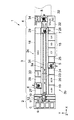
図1は本発明の搬送装置が適用されるLCD基板の塗布現像処理システムを示す平面図であり、図2はその正面図、また図3はその背面図である。
【0025】
この塗布現像処理システム1は、複数のガラス基板Gを収容するカセットCを載置するカセットステーション2と、基板Gにレジスト塗布および現像を含む一連の処理を施すための複数の処理ユニットを備えた処理部3と、露光装置32との間で基板Gの受け渡しを行うためのインターフェース部4とを備えており、処理部3の両端にそれぞれカセットステーション2及びインターフェース部4が配置されている。
【0026】
カセットステーション2は、カセットCと処理部3との間でLCD基板の搬送を行うための搬送機構10を備えている。そして、カセットステーション2においてカセットCの搬入出が行われる。また、搬送機構10はカセットの配列方向に沿って設けられた搬送路12上を移動可能な搬送アーム11を備え、この搬送アーム11によりカセットCと処理部3との間で基板Gの搬送が行われる。
【0027】
処理部3には、カセットステーション2におけるカセットCの配列方向(Y方向)に垂直方向(X方向)に延設された主搬送部3aと、この主搬送部3aに沿って、レジスト塗布処理ユニット(CT)を含む各処理ユニットが並設された上流部3b及び現像処理ユニット(DEV)18を含む各処理ユニットが並設された下流部3cとが設けられている。
【0028】
主搬送部3aには、X方向に延設された搬送路31と、この搬送路31に沿って移動可能に構成されガラス基板GをX方向に搬送する搬送シャトル23とが設けられている。この搬送シャトル23は、例えば支持ピンにより基板Gを保持して搬送するようになっている。また、主搬送部3aのインターフェース部4側端部には、処理部3とインターフェース部4との間で基板Gの受け渡しを行う垂直搬送ユニット7が設けられている。
【0029】
上流部3bにおいて、カセットステーション2側端部には、基板Gに洗浄処理を施すスクラバ洗浄処理ユニット(SCR)20が設けられ、このスクラバ洗浄処理ユニット(SCR)20の上段に基板G上の有機物を除去するためのエキシマUV処理ユニット(e−UV)19が配設されている。
【0030】
スクラバ洗浄処理ユニット(SCR)20の隣には、ガラス基板Gに対して熱的処理を行うユニットが多段に積み上げられた熱処理系ブロック24及び25が配置されている。これら熱処理系ブロック24と25との間には、垂直搬送ユニット5が配置され、搬送アーム5aがZ方向及び水平方向に移動可能とされ、かつθ方向に回動可能とされているので、両ブロック24及び25における各熱処理系ユニットにアクセスして基板Gの搬送が行われるようになっている。なお、上記処理部3における垂直搬送ユニット7についてもこの垂直搬送ユニット5と同一の構成を有している。
【0031】
図2に示すように、熱処理系ブロック24には、基板Gにレジスト塗布前の加熱処理を施すベーキングユニット(BAKE)が2段、HMDSガスにより疎水化処理を施すアドヒージョンユニット(AD)が下から順に積層されている。一方、熱処理系ブロック25には、基板Gに冷却処理を施すクーリングユニット(COL)が2段、アドヒージョンユニット(AD)が下から順に積層されている。
【0032】
熱処理系ブロック25に隣接してレジスト処理ブロック15がX方向に延設されている。このレジスト処理ブロック15は、基板Gにレジストを塗布するレジスト塗布処理ユニット(CT)と、減圧により前記塗布されたレジストを乾燥させる減圧乾燥ユニット(VD)と、基板Gの周縁部のレジストを除去するエッジリムーバ(ER)とが一体的に設けられて構成されている。このレジスト処理ブロック15には、レジスト塗布処理ユニット(CT)からエッジリムーバ(ER)にかけて移動する図示しないサブアームが設けられており、このサブアームによりレジスト処理ブロック15内で基板Gが搬送されるようになっている。
【0033】
レジスト処理ブロック15に隣接して多段構成の熱処理系ブロック26が配設されており、この熱処理系ブロック26には、基板Gにレジスト塗布後の加熱処理を行うプリベーキングユニット(PREBAKE)が3段積層されている。
【0034】
下流部3cにおいては、図3に示すように、インターフェース部4側端部には、熱処理系ブロック29が設けられており、これには、クーリングユニット(COL)、露光後現像処理前の加熱処理を行うポストエクスポージャーベーキングユニット(PEBAKE)が2段、下から順に積層されている。
【0035】
熱処理系ブロック29に隣接して現像処理を行う現像処理ユニット(DEV)18がX方向に延設されている。この現像処理ユニット(DEV)18の隣には熱処理系ブロック28及び27が配置され、これら熱処理系ブロック28と27との間には、上記垂直搬送ユニット5と同一の構成を有し、両ブロック28及び27における各熱処理系ユニットにアクセス可能な垂直搬送ユニット6が設けられている。また、現像処理ユニット(DEV)18端部の上には、i線処理ユニット(i―UV)33が設けられている。
【0036】
熱処理系ブロック28には、クーリングユニット(COL)、基板Gに現像後の加熱処理を行うポストベーキングユニット(POBAKE)が2段、下から順に積層されている。一方、熱処理系ブロック27も同様に、クーリングユニット(COL)、ポストベーキングユニット(POBAKE)が2段、下から順に積層されている。
【0037】
インターフェース部4には、正面側にタイトラー及び周辺露光ユニット(Titler/EE)22が設けられ、垂直搬送ユニット7に隣接してエクステンションクーリングユニット(EXTCOL)35が、また背面側にはバッファカセット34が配置されており、これらタイトラー及び周辺露光ユニット(Titler/EE)22とエクステンションクーリングユニット(EXTCOL)35とバッファカセット34と隣接した露光装置32との間で基板Gの受け渡しを行う垂直搬送ユニット8が配置されている。この垂直搬送ユニット8も上記垂直搬送ユニット5と同一の構成を有している。
【0038】
以上のように構成された塗布現像処理システム1の処理工程については、先ずカセットC内の基板Gが処理部3部における上流部3bに搬送される。上流部3bでは、エキシマUV処理ユニット(e−UV)19において表面改質・有機物除去処理が行われ、次にスクラバ洗浄処理ユニット(SCR)20において、基板Gが略水平に搬送されながら洗浄処理及び乾燥処理が行われる。続いて熱処理系ブロック24の最下段部で垂直搬送ユニットにおける搬送アーム5aにより基板Gが取り出され、同熱処理系ブロック24のベーキングユニット(BAKE)にて加熱処理、アドヒージョンユニット(AD)にて疎水化処理が行われ、熱処理系ブロック25のクーリングユニット(COL)による冷却処理が行われる。
【0039】
次に、基板Gは搬送アーム5aから搬送シャトル23に受け渡される。そしてレジスト塗布処理ユニット(CT)に搬送され、レジストの塗布処理が行われた後、減圧乾燥処理ユニット(VD)にて減圧乾燥処理、エッジリムーバ(ER)にて基板周縁のレジスト除去処理が順次行われる。
【0040】
次に、基板Gは搬送シャトル23から垂直搬送ユニット7の搬送アームに受け渡され、熱処理系ブロック26におけるプリベーキングユニット(PREBAKE)にて加熱処理が行われた後、熱処理系ブロック29におけるクーリングユニット(COL)にて冷却処理が行われる。続いて基板Gはエクステンションクーリングユニット(EXTCOL)35にて冷却処理されるとともに露光装置にて露光処理される。
【0041】
次に、基板Gは垂直搬送ユニット8及び7の搬送アームを介して熱処理系ブロック29のポストエクスポージャーベーキングユニット(PEBAKE)に搬送され、ここで加熱処理が行われた後、クーリングユニット(COL)にて冷却処理が行われる。そして基板Gは垂直搬送ユニット7の搬送アームを介して、現像処理ユニット(DEV)18において基板Gは略水平に搬送されながら現像処理、リンス処理及び乾燥処理が行われる。
【0042】
次に、基板Gは熱処理系ブロック28における最下段から垂直搬送ユニット6の搬送アーム6aにより受け渡され、熱処理系ブロック28又は27におけるポストベーキングユニット(POBAKE)にて加熱処理が行われ、クーリングユニット(COL)にて冷却処理が行われる。そして基板Gは搬送機構10に受け渡されカセットCに収容される。
【0043】
図4(a)は上記スクラバ洗浄処理ユニット(SCR)20を示す概略側面図である。このスクラバ洗浄処理ユニット(SCR)20には、ガラス基板Gを搬送するためのコロ式の搬送ローラ38が複数設けられている。搬送ローラ38の両端には、昇降動作により他の処理部との間で基板の受け渡しを行う受け渡しピン39が配置されており、この両受け渡しピン39の間には、この基板の搬送上流側(図において左側)から、ロールブラシ洗浄室36、スプレー洗浄室37及び本発明に係る乾燥処理装置40が順に配置されている。ロールブラシ洗浄室36にはロールブラシ45が設けられ、スプレー洗浄室37には、洗浄液を噴出するスプレー式のノズル46が設けられている。なお、スプレー式のノズル46は、図示するように基板の表面側だけでなく、基板裏面側にも更に配置するようにしてもかまわない。
【0044】
このようなスクラバ洗浄処理ユニット(SCR)20においては、先ずロールブラシ洗浄室36で基板上の比較的大きいゴミを除去洗浄した後、スプレー洗浄室37で微細なゴミを除去洗浄し、乾燥処理装置40で乾燥処理される。
【0045】
図4(b)は、上記現像処理ユニット(DEV)18を示す概略側面図である。この現像処理ユニット(DEV)18には、スクラバ洗浄処理ユニット(SCR)20と同様に、コロ式の搬送ローラ38及び受け渡しピン39が配置されている。この両受け渡しピン39の間には、搬送上流側(図において左側)から、プリウェット処理室41、現像処理室42、リンス処理室43及び本発明に係る上記と同一の乾燥処理装置40が順に配置されている。プリウェット処理室41には、プリウェットノズル47が、また現像処理室42には現像液を吐出する現像液ノズル48がそれぞれ設けられ、またリンス処理室43にはリンスノズル49が設けられている。
【0046】
このような現像処理ユニット(DEV)18においては、先ず、プリウェット処理室41で、現像液吐出の際の基板に対するインパクト軽減のために、基板をプリウェットし、次に現像処理室42で現像液が吐出されて現像され、そしてリンス処理室43で現像液が洗い流され、最後に乾燥処理装置40で乾燥処理される。
【0047】
なお、現像処理室42においては、現像時間を確保するために、搬送ローラ38を逆回転させ基板Gを往復させながら現像処理を行っている。
【0048】
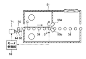
図5及び図6は、第1の実施形態に係る乾燥処理装置40の平断面図及び側断面図である。この乾燥処理装置40のチャンバ51内の空間は、搬送上流側(図5及び図6において左側)から仕切り板63によって仕切られている。このチャンバ51の上流端及び下流端には、それぞれ基板Gを搬入及び搬出するための開口部51a及び51bが形成されている。
【0049】
仕切り板63の下端切り欠き部63aには、搬送される基板Gに対し清浄エアを噴出して基板Gを乾燥させる長尺形状のエアナイフノズル53a及び53bが搬送される基板Gを挟みこむように上下に配置されている。これらエアナイフ53a及び53bは基板Gに対し鉛直方向から例えば40°以上傾けて配置されており、エアが基板面の鉛直方向に対して40°以上傾いて噴出されるようになっている。
【0050】
図7(a)に示すように、両エアナイフ53a及び53bは同一の構成を有しており、例えば内部に供給口72から供給されたエアを一旦滞留させるバッファ室73を有し、このバッファ室73から基板Gに対して線状にエアを噴出させるためのスリット74が形成されている。
【0051】
それぞれの搬送ローラ38には、例えば、その軸心部材の一端に複数の歯車75が取り付けられ、これらの歯車75にそれぞれ噛合する歯車68が軸部材44にそれぞれ取り付けられている。この軸部材44は、モータ71の駆動により回転するようになっており、モータ71の駆動により搬送ローラ38が回転し基板Gを搬送するようになっている。
【0052】
図6を参照して、エアナイフ53a、53bには、ブロアファン60から、フィルタ部59及び供給管66を介してエアが供給されるようになっている。このブロアファン60は、例えばクリーンルーム内あるいは外部の空気を取り入れている。フィルタ部59には、例えば粗いパーティクル用のプレフィルタ61と細かいパーティクル用のULPAフィルタ62が設けられている。このULPAフィルタ62は、HEPAフィルタであってもよい。
【0053】
このように、ブロアファン60を設けることにより、工場の高圧エアコンプレッサを使用する必要がなくなり、工場用力を削減し省エネルギー化を図ることができる。特に基板Gの大型に伴い用力も増大する傾向にあるのでブロアファンを使用する効果は大きい。また、ブロアファンはエアコンプレッサに比べ経済的にも極めて有利である。
【0054】
制御系50はCPU56、メモリ57、インバータ回路58を有しており、ブロアファン60はこの制御系50により周波数制御されるようになっている。例えば供給管66に設けられ当該管内のエアの流量を計測するフローメータ65の計測結果に基づいて、ブロアファン60から吐出されるエアの流量が制御されるようになっている。これにより、フィルタ部59の目詰まり等によりエアナイフ53a、53bに供給されるエアの流量が減少した場合であっても、フローメータ65の計測結果をフィードバックすることによりエアナイフ53a、53bへ常に所望の流量でエアを供給することができる。
【0055】
チャンバ51の下流側上部には、開口が形成されここにファンフィルタユニット52が設置されている。このファンフィルタユニット52は、例えばクリーンルーム内あるいは外部のエアを清浄にしてチャンバ51内に取り入れ、この取り入れたエアを、搬送上流側の上下部に設けられた排気口55a及び55bから排気している。排気口55a及び55bには図示しないバキューム装置等に接続されている。これにより、チャンバ51内の気圧を、下流側から上流側に向かうにつれて低くなるように制御しており、この気圧の制御により液切りによる基板G上の処理液をも効率良く排出することができる。
【0056】
エアナイフ53a、53bより搬送上流側には、例えば発光部Sa及び受光部Sbを備えた光センサSが配置されている。例えば、基板Gによって光センサSの光が遮光されると、その情報が制御系50に伝えられるようになっており、これに基づきブロアファン60の周波数を制御してエアナイフ53a、53bへ供給されるエアの量を調整できるようになっている。
【0057】
センサSにより基板Gの前端を検知すると、図7(a)に示すように、エアナイフ53a、53bから噴出されるエアの風量を待機時よりも多く例えばし、基板Gの前端付近の領域Gaに付着した処理液を除去する。この前端付近の領域Gaとしては、基板Gの前端からの距離が1cm〜5cmの部位である。この領域Gaで噴出されるエア量は、例えば基板の幅が700mmの場合で1000(l/min)である。
【0058】
そして、センサSが基板前端を検知してから所定時間経過後、基板前端付近及び後端付近以外の領域Gcにおいては、図7(b)に示すように、領域Gaにおける噴出量よりもを少なくしてエアを噴出して処理液を除去し、図7(c)に示すように、センサSが基板前端を検知してから所定時間経過後に再び、基板Gの後端からの距離が1cm〜5cmの部位である後端付近の領域Gbに付着した処理液を除去する。センサSが基板前端を検知してから所定時間経過後というのは、基板搬送速度と基板Gのサイズにより既定値であり、この値は予め制御系50にインプットされている。
【0059】
ここで、領域Gcで噴出されるエア量は、例えば700mmの場合で800(l/min)であり、領域Gbで噴出されるエア量は、例えば700mmの場合で1300(l/min)である。
【0060】
これにより、従来において一定のエア風量では除去しきれなかった処理液を、本実施形態によれば基板全面にわたってばらつきなく、完全に除去することができ乾燥ムラの発生を防止することができる。従って、特に基板の前端付近及び後端付近で残存することがあった処理液を除去することができる。
【0061】
また、従来において処理液を完全に除去するために、基板全面にわたり風量を多くして一定の風量でエアを噴出していたのに比べ、本実施形態では領域Gcにおいては噴出するエアの風量を少なくしている。従って、ブロアファン60の電力消費を削減することができ、またエア消費をも削減することができて省エネルギー化に寄与する。
【0062】
更に、基板の領域Gcにおいてエア風量を少なくしていることにより、一定多風量の場合に比べ、チャンバ51内の乱気流を抑制できチャンバ51内に飛散するミスト状の処理液の量を減らすことができる。これにより、ミストが再び基板Gに付着することはなく乾燥性能が向上する。
【0063】
なお、ブロアファン60により変化したエア量の、エアナイフへのレスポンス時間にロスがあるため、例えば、図6においてセンサSの配置位置をエアナイフ53a及び53bから所定距離だけ離すようにすることが好ましい。
【0064】
また、領域Ga内において、エア量を例えば1000(l/min)から段階的若しくは線形的に減少させてもよく、又は、領域Gcから領域Gbにかけて段階的に若しくは線形的に、エア量を例えば800(l/min)から1300(l/min)に増加させてもよく、このように制御することにより急激なエア量の変化による基板近傍の気流の乱れ及びミストの発生を抑制できる。
【0065】
次に、図8を参照して本発明の第2の実施形態について説明する。なお、図8において、図5及び図6における構成要素と同一のものについては同一の符号を付すものとし、その説明を省略する。
【0066】
本実施形態においては、センサSが基板Gの前端を検知すると、この情報がモータ71の回転数を制御するモータ制御部69に伝達されて搬送ローラ38の回転速度を落とす。これによって基板Gの搬送が減速され、例えば図7に示した場合と同様に、基板Gの前端付近の領域Gaにエアを供給し、次に所定時間経過後に、搬送速度を上げて領域Gcにエアを供給し、更に所定時間経過後に搬送速度を領域Gaにエアを供給する場合と同じ速度となるように減速して領域Gbにエアを供給する。そして、基板Gの後端がエアナイフ53a及び53bを通過した後に、再び搬送速度を上げる。ここで、センサSが基板前端を検知してから所定時間経過後というのは、基板搬送速度と基板Gのサイズにより既定値であり、この値は予めモータ制御部69にインプットされている。なお、例えばエアの噴出される風量は領域Ga、Gc及びGbにおいて一定としている。
【0067】
このように、領域Ga及びGbにエアが供給されるときの基板Gの搬送速度を、それら以外の領域Gcにエアが供給されるときの場合に比べて遅くすることにより、基板全面にわたってばらつきなく、完全に除去することができる。従って、特に基板の前端付近及び後端付近で残存することがあった処理液を除去することができる。
【0068】
なお、領域Gbにエアが供給されるときの基板Gの搬送速度を、領域Gaにエアが供給されるときの基板Gの搬送速度より遅くしてもよく、この場合、基板の前端より液残りしやすい後端付近での処理液の除去性能を向上させることができる。
【0069】
図9は、本発明の第3の実施形態を示している。なお、図9において、図8における構成要素と同一のものについては同一の符号を付すものとし、その説明を省略する。
【0070】
本実施形態では、基板Gの前端を検知するセンサとして、例えばマイク70を用いている。これは、エアナイフ53a及び53bからエアが噴出しているときに、基板Gがこのエアナイフに接近すると、エアが基板に当り始めることにより除々に音がそれまでより強くなり、かつ周波数が高くなる現象を利用するものである。
【0071】
そしてこの「音」は、図7に示す基板の領域Ga付近においては、そのように強くなりかつ周波数が高くなるが、領域Gcにおいては、領域Gaに比べると弱くなりなりかつ周波数が低くなる傾向にある。そして領域Gbにおいては再び領域Gaと同様に「音」が強くなり、かつ周波数が高くつまり音が高くなる。すなわち「音」の強さ及び周波数は、Ga≒Gb>Gcとなる。
【0072】
この「音」の変動に基づいて、上記第2の実施形態と同様に、基板Gの搬送速度を変化させることにより、基板全面にわたってばらつきなく、完全に除去することができる。従って、特に基板の前端付近及び後端付近で残存することがあった処理液を除去することができる。
【0073】
ここで「音」は、その強さ又は周波数だけでなく、例えば減衰度、複数和音の組み合わせ等により様々な「音質」や「音色」があり、とにかく「音」の変動を検知できれば、基板を検知することができる。
【0074】
なお、本実施形態においては、「音」が変化するごとにこれをフィードバックして基板の搬送速度を制御するようにしたが、基板前端の「音」を最初に一度検出するのみで、あとはこの最初の検出から所定時間経過後に搬送速度を変化させるようにしてもかまわない。
【0075】
図10は、他の実施形態に係るエアナイフを示す断面図である。このエアナイフ80内は、仕切板81により3つのバッファ室73a、73b及び73cが形成されている。これら各バッファ室73a、73b及び73cへそれぞれエアを供給するための供給管77、78及び79が接続され、また、それぞれのエアの供給量を調節するバルブ83、84及び85が設けられている。
【0076】
本実施形態では、このバルブ83、84及び85の開度をそれぞれ大、中及び小とし、各バッファ室73a、73b及び73cから噴出されるエアの風量をそれそれ大、中及び小とする。
【0077】
例えば、図11に示すように、矢印Aで示す方向に搬送される基板G上の図中右側へ効率良く液切りするために、搬送方向Aに対して所定の角度α=10°〜20°でエアナイフ80の長手方向を傾けて配置させている場合、バッファ室73aから噴出されるエア量をバッファ室73cから噴出されるエア量より多くすることにより、基板Gの図中左側にある処理液を右側よりも遠くへ除去することができ、効率良く乾燥処理を行うことができる。特に、排気口55aの位置がエアナイフ80によるエア噴出の方向であるので、効果は大である。
【0078】
本発明は以上説明した実施形態には限定されるものではなく、種々の変形が可能である。
【0079】
例えば、上記第1の実施形態におけるエアの風量制御と、第2の実施形態における搬送速度の制御を同時に行うようにしてもよい。
【0080】
また、上記各実施形態においては、搬送される基板の前端を検知するセンサとして光センサSやマイクを使用したが、これに限らず、基板Gの重量により反応する振り子式センサを使用することもできる。
【0081】
また、上記第1の実施形態において、エアナイフ53a及び53bの下流側に更に同一のエアナイフを2つ、搬送される基板の上下に設ける構成としてもよい。この場合、上流側のエアナイフと下流側のエアナイフそれぞれ別個にブロアファンを接続し、搬送される基板のサイズや搬送速度を記憶した上で両ブロアファンをそれぞれ別個にインバータ制御することにより、本発明の目的を達成することができる。
【0082】
また、このようにエアナイフ53a及び53bの下流側に更に設ける際に、下流側のエアナイフに対する領域Ga、Gb、Gcに対しても前述したような制御を行ってもよく、当該下流側のエアナイフから領域Ga、Gbに対する単位面積当りのエア量が、上流側のエアナイフから領域Ga、Gbに対する単位面積当りのエア量より多くなるように制御してもよい。このようにすれば、処理液が残りやすい基板の前端又は後端近傍を確実に乾燥できる。また、上流側のエアナイフが主で、下流側のエアナイフが補助という意味合いが強ければ、逆に下流側のエアナイフからの領域Ga、Gbに対する単位面積当りのエア量を上流のエアナイフに対する単位面積当りのエア量より少なく制御することにより、更にランニングコストやミストを抑制できる。なお、領域GcはGa及びGbに比べ液切りが容易であり、領域Gcは上流側のエアナイフでほぼ液切りできているので、下流側のエアナイフからの領域Gcに対する単位面積当りのエア量を上流側のエアナイフからの領域Gcに対するエア量より少なくしてもよい。
【0083】
更に、図10においてエアナイフのバッファ室を3つとしたが、更に仕切板81を増やし、基板に噴出される風量を更に詳細に制御するようにしてもよい。
【0084】
【発明の効果】
以上説明したように、本発明によれば、基板全面にわたり効率良くかつ処理液を残すことなく乾燥処理を行うことができる。また、エアの消費量及び電力を削減することができ、省エネルギー化を図ることができる。
【図面の簡単な説明】
【図1】本発明が適用される塗布現像処理システムの全体構成を示す平面図である。
【図2】図1に示す塗布現像処理システムの正面図である。
【図3】図1に示す塗布現像処理システムの背面図である。
【図4】(a)スクラバ洗浄処理ユニット(SCR)、(b)現像処理ユニット(DEV)を示す概略側面図である。
【図5】本発明の第1の実施形態に係る乾燥処理装置を示す平断面図である。
【図6】図5に示す乾燥処理装置の側断面図及び概念構成図である。
【図7】第1の実施形態に係る乾燥作用を示す側面図である。
【図8】本発明の第2の実施形態に係る乾燥処理装置を示す側断面図である。
【図9】本発明の第3の実施形態に係る乾燥処理装置を示す側断面図である。
【図10】本発明の他の実施形態に係るエアナイフを示す断面図である。
【図11】図10に示すエアナイフを使用した場合の乾燥作用を示す平面図である。
【符号の説明】
G…ガラス基板
S…光センサ
Ga、Gb…基板前端付近及び後端付近の領域
Gc…基板のGa、Gb以外の領域
A…搬送方向
α…所定の角度
38…搬送ローラ
40…乾燥処理装置
50…制御系
53a、53b…エアナイフノズル
60…ブロアファン
69…モータ制御部
70…マイク
71…モータ
80…エアナイフ
83、84、85…バルブ[0001]
BACKGROUND OF THE INVENTION
The present invention relates to a substrate drying method and a substrate drying apparatus for drying a glass substrate after performing a predetermined liquid treatment on a glass substrate used in a liquid crystal display (LCD) or the like in a manufacturing process of a liquid crystal device. And a liquid processing apparatus .
[0002]
[Prior art]
In the LCD manufacturing process, a photolithography technique similar to that used for manufacturing semiconductor devices is used to form an ITO (Indium Tin Oxide) thin film or electrode pattern on a glass substrate for LCD. In the photolithography technique, a photoresist is applied to a glass substrate, which is exposed and further developed.
[0003]
Conventionally, a series of processes such as resist coating, exposure, and development is performed by a coating and developing system that performs coating, development, baking, washing, and other processes.
[0004]
In the development processing and cleaning processing in this coating and developing processing system, for example, while the substrate is transported almost horizontally by a roller-type transport roller, a processing solution such as a developing solution or a cleaning solution is supplied to the substrate to perform development processing and cleaning processing. Is going. Then, for example, high-pressure air is ejected from the substrate by an air knife nozzle disposed on the downstream side of the transport to remove (remove) the processing liquid on the substrate and perform a drying process.
[0005]
[Problems to be solved by the invention]
However, in the conventional drying process, since a constant air volume is ejected from the air knife, for example, even if the liquid can be sufficiently drained near the center of the glass substrate, the constant air volume is near the edge of the substrate. With this air flow, the liquid could not be drained accurately, and there was a problem that the treatment liquid remained in the vicinity of the end.
[0006]
Therefore, in order to dry a single substrate uniformly with a constant airflow, an airflow must be blown over the entire surface of the substrate so that the processing liquid does not remain near the center or end of the substrate. The amount of air consumed was increasing. In addition, from the viewpoint of the recent increase in the size of glass substrates, the amount of air consumption is increasing.
[0007]
In view of the circumstances as described above, an object of the present invention is to provide a substrate drying method and a substrate drying apparatus that can reduce air consumption and suppress uneven drying.
[0008]
[Means for Solving the Problems]
In order to achieve the above object, a substrate drying method according to a first aspect of the present invention is a substrate drying method in which a substrate is dried while being transported. (A) Areas near the front end and the rear end of the transported substrate. A step of ejecting air with a first air volume, and (b) a step of ejecting air with a second air volume different from the first air volume in a region other than the vicinity of the front end and the vicinity of the rear end of the substrate. It has.
[0009]
According to such a configuration, according to the present invention, it is possible to completely remove the processing liquid that could not be removed with a constant air flow rate over the entire surface of the substrate, and prevent the occurrence of drying unevenness. Can do. For example, by increasing the first air volume more than the second air volume, it is possible to remove the processing liquid that may remain near the front edge and the rear edge of the substrate.
[0010]
Further, in the prior art, in order to completely remove the processing liquid, the air volume is increased over the entire surface of the substrate and air is blown at a constant air volume. In the present invention, in the region other than the vicinity of the front end and the vicinity of the rear end. Reduces the volume of air blown out. Therefore, for example, the power consumption of the air supply source can be reduced, and the air consumption can be reduced, contributing to energy saving.
[0011]
Furthermore, by reducing the air flow rate in areas other than the vicinity of the front end and near the back end of the substrate, the amount of mist-like processing liquid that can be scattered, for example, can suppress turbulence in the drying processing chamber, compared to the case of a constant high air flow rate. Can be reduced. Thereby, the mist does not adhere to the substrate again, and the drying performance is improved.
[0012]
According to one aspect of the present invention, in the step (a), (c) the front end of the substrate to be transported is detected, and air is ejected to the region near the front end with a first air volume based on the detection. And (d) a step of ejecting air with a first air volume in a region near the rear end after a predetermined time has elapsed after detecting the front end. For example, it is possible to detect the step (c) with an optical sensor. On the other hand, the detection in the step (c) can be performed based on the fluctuation of “sound” when air hits the substrate . For example, by changing the transport speed of the substrate based on changes in the intensity, frequency, timbre, etc. of this “sound”, the processing liquid can be completely removed over the entire surface of the substrate, preventing the occurrence of uneven drying. can do.
[0013]
A substrate drying method according to a second aspect of the present invention is a substrate drying method in which air is blown to a substrate at a predetermined position while the substrate is being transported, and (a) near the front end of the substrate to be transported. And a step of setting the substrate transport speed to the first speed when the vicinity of the rear end reaches the predetermined position, and (b) the substrate after the vicinity of the front end and the vicinity of the rear end have passed the predetermined position. And a second speed different from the first speed.
[0014]
According to such a configuration, for example, by making the first transport speed slower than the second transport speed, the processing liquid can be completely removed without variation over the entire surface of the substrate, thereby preventing the occurrence of drying unevenness. be able to. In particular, it is possible to remove the processing liquid that may remain near the front end and the rear end of the substrate.
[0015]
According to one aspect of the present invention, the step (a) includes (c) detecting a front end of the substrate to be transported, and setting the substrate transport speed to a first speed based on the detection; (D) After detecting the front end, a step of setting the substrate transport speed to a second speed after a predetermined time has elapsed. For example, the step (c) can be performed by an optical sensor, or can be performed based on the fluctuation of sound when air hits the substrate.
[0016]
According to an aspect of the present invention, the air is ejected, and a long nozzle having a predetermined angle with respect to one side of the front end or the rear end of the substrate is provided. The amount of air blown from a portion closer to the front end of the substrate is made different from the amount of air blown from a portion closer to the rear end of the substrate. For example, the amount of air blown from the portion closer to the rear end of the substrate is made larger than the amount of air blown from the portion closer to the front end, so that the air blown from the side closer to the rear end is scattered. The treatment liquid can be located farther than the treatment liquid scattered by the jet air from the side close to the rear end, and the drying process can be performed efficiently.
[0017]
A substrate drying apparatus according to a first aspect of the present invention includes: a transport unit that transports a substrate; an air ejection unit that ejects air to the substrate transported by the transport unit to dry the substrate; and the air ejection The air volume blown from the means is set to a first air volume in a region near the front end and the rear end of the substrate to be transported, and is different from the first air volume in a region other than the vicinity of the front end and the vicinity of the rear end. Means for controlling the air volume to 2.
[0018]
According to such a configuration, according to the present invention, it is possible to completely remove the processing liquid that could not be removed with a constant air flow rate over the entire surface of the substrate, and prevent the occurrence of drying unevenness. Can do. In particular, by making the first air volume larger than the second air volume, it is possible to remove the processing liquid that may remain near the front edge and the rear edge of the substrate.
[0019]
Further, in the prior art, in order to completely remove the processing liquid, the air volume is increased over the entire surface of the substrate and air is blown at a constant air volume. In the present invention, in the region other than the vicinity of the front end and the vicinity of the rear end. Reduces the volume of air blown out. Therefore, for example, the power consumption of the air supply source can be reduced, and the air consumption can be reduced, contributing to energy saving.
[0020]
A substrate drying apparatus according to a second aspect of the present invention includes a transport unit that transports a substrate, an air ejection unit that ejects air to the substrate transported by the transport unit, and dries the substrate, and the transport unit. When the vicinity of the front end and the vicinity of the rear end of the substrate reaches a predetermined position , the substrate transfer speed is set to the first speed, and after the vicinity of the front end and the vicinity of the rear end passes the predetermined position, the substrate is transferred. Means for setting the speed to a second speed different from the first speed.
[0021]
According to such a configuration, for example, by making the first transport speed slower than the second transport speed, the processing liquid can be completely removed without variation over the entire surface of the substrate, thereby preventing the occurrence of drying unevenness. be able to. In particular, it is possible to remove the processing liquid that may remain near the front end and the rear end of the substrate.
According to one aspect of the present invention, the air volume is gradually changed from the first air volume to the second air volume or from the second air volume to the first air volume.
According to one aspect of the invention, the speed of the substrate is varied.
A liquid processing apparatus according to a third aspect of the present invention is a liquid processing apparatus that supplies a liquid to a substrate to perform liquid processing, and includes a transport unit that transports the substrate, and a substrate transported by the transport unit. A means for supplying liquid, an air ejection means for blowing air to the substrate transported by the transport means to dry the substrate, and an air flow rate of air ejected from the air ejecting means. Means for controlling the first air volume in a region near the front end and in the vicinity of the rear end, and controlling to a second air volume smaller than the first air volume in a region other than the vicinity of the front end and the vicinity of the rear end.
A liquid processing apparatus according to a fourth aspect of the present invention is a liquid processing apparatus that supplies a liquid to a substrate to perform liquid processing, and includes a transport unit that transports the substrate, and a substrate transported by the transport unit. A means for supplying liquid, an air ejection means for blowing air to the substrate transported by the transport means to dry the substrate, and an air flow rate of air ejected from the air ejecting means. The first air volume is set in a region near the front end of the substrate, the second air volume is set lower than the first air volume in a region other than the vicinity of the front end and the vicinity of the rear end, and the second air volume is decreased in the region near the rear end of the substrate to be transferred. Means for controlling the air volume to be larger than the air volume of 1.
According to one aspect of the present invention, in the region near the front edge of the substrate, the air volume is reduced stepwise or linearly from the first air volume, and / or other than near the front edge and near the rear edge of the substrate. The air volume is increased stepwise or linearly from the region to the region near the rear end of the substrate.
A liquid processing apparatus according to a fourth aspect of the present invention is a liquid processing apparatus that supplies a liquid to a substrate to perform liquid processing, and includes a transport unit that transports the substrate, and a substrate transported by the transport unit. A means for supplying liquid, an air ejection means for blowing air to the substrate conveyed by the conveying means to dry the substrate, and a substrate when the front end of the conveyed substrate reaches a predetermined position. Air is supplied to an area near the front edge of the substrate at a first speed, and after a predetermined time has passed, the air is increased to supply air in areas other than the vicinity of the front edge and the rear edge of the substrate, and for a predetermined time. Means for decelerating the rear conveyance speed, supplying air to a region near the rear edge of the substrate, and controlling the rear edge of the substrate to increase again after passing through the air ejecting means.
According to an aspect of the present invention, the substrate transport speed when air is supplied to the region near the rear end of the substrate is slower than the first transport speed.
According to one aspect of the present invention, it is characterized by having means for detecting that the front end of the substrate has reached a predetermined position by detecting fluctuations in the sound of air.
[0022]
Further features and advantages of the present invention will become more apparent by referring to the attached drawings and description of embodiments of the invention.
[0023]
DETAILED DESCRIPTION OF THE INVENTION
Hereinafter, embodiments of the present invention will be described with reference to the drawings.
[0024]
FIG. 1 is a plan view showing a coating and developing system for an LCD substrate to which the conveying apparatus of the present invention is applied, FIG. 2 is a front view thereof, and FIG. 3 is a rear view thereof.
[0025]
The coating and developing
[0026]
The
[0027]
The
[0028]
The
[0029]
In the
[0030]
Next to the scrubber cleaning processing unit (SCR) 20, thermal processing blocks 24 and 25 are arranged in which units for performing thermal processing on the glass substrate G are stacked in multiple stages. Between these heat treatment blocks 24 and 25, the
[0031]
As shown in FIG. 2, the heat
[0032]
A resist
[0033]
A multi-stage heat
[0034]
In the
[0035]
A development processing unit (DEV) 18 that performs development processing adjacent to the
[0036]
In the
[0037]
The
[0038]
Regarding the processing steps of the coating and developing
[0039]
Next, the substrate G is transferred from the
[0040]
Next, the substrate G is transferred from the
[0041]
Next, the substrate G is transferred to the post-exposure baking unit (PEBAKE) of the heat
[0042]
Next, the substrate G is transferred from the lowermost stage in the heat
[0043]
FIG. 4A is a schematic side view showing the scrubber cleaning unit (SCR) 20. The scrubber cleaning unit (SCR) 20 is provided with a plurality of roller-
[0044]
In such a scrubber cleaning unit (SCR) 20, first, relatively large dust on the substrate is removed and cleaned in the roll
[0045]
FIG. 4B is a schematic side view showing the development processing unit (DEV) 18. In the development processing unit (DEV) 18, similarly to the scrubber cleaning processing unit (SCR) 20, roller-
[0046]
In such a development processing unit (DEV) 18, first, the substrate is pre-wet in the
[0047]
In the
[0048]
5 and 6 are a plan sectional view and a side sectional view of the drying
[0049]
Upper and lower
[0050]
As shown in FIG. 7A, both
[0051]
For example, a plurality of
[0052]
With reference to FIG. 6, air is supplied to the
[0053]
Thus, by providing the
[0054]
The control system 50 has a CPU 56, a memory 57, and an inverter circuit 58, and the
[0055]
An opening is formed in the upper part on the downstream side of the
[0056]
An optical sensor S including, for example, a light emitting unit Sa and a light receiving unit Sb is disposed on the upstream side of conveyance from the
[0057]
When the front end of the substrate G is detected by the sensor S , as shown in FIG. 7A, the amount of air blown from the
[0058]
Then, after a predetermined time has elapsed since the sensor S detects the front end of the substrate, in the region Gc other than the vicinity of the front end of the substrate and the vicinity of the rear end, as shown in FIG. Then, the processing liquid is removed by ejecting air, and as shown in FIG. 7C, the distance from the rear end of the substrate G is 1 cm to again after a predetermined time elapses after the sensor S detects the front end of the substrate. The treatment liquid adhering to the region Gb near the rear end, which is a 5 cm portion, is removed. The predetermined time after the sensor S detects the front edge of the substrate is a predetermined value depending on the substrate conveyance speed and the size of the substrate G, and this value is input to the control system 50 in advance.
[0059]
Here, the amount of air ejected in the region Gc is 800 (l / min) in the case of 700 mm, for example, and the amount of air ejected in the region Gb is 1300 (l / min) in the case of 700 mm, for example. .
[0060]
Thereby, according to the present embodiment, the processing liquid that could not be removed with a constant air flow rate can be completely removed over the entire surface of the substrate and the occurrence of drying unevenness can be prevented. Accordingly, it is possible to remove the processing liquid that may remain in the vicinity of the front end and the rear end of the substrate.
[0061]
Further, in the present embodiment, in the region Gc, the air volume of the air to be ejected is compared with the case where the air volume is increased over the entire surface of the substrate and air is ejected at a constant air volume in order to completely remove the processing liquid. Less. Therefore, the power consumption of the
[0062]
Furthermore, by reducing the air flow rate in the substrate region Gc, the turbulent air flow in the
[0063]
In addition, since there is a loss in the response time to the air knife for the air amount changed by the
[0064]
In the region Ga, the air amount may be decreased stepwise or linearly from, for example, 1000 (l / min), or the air amount may be decreased stepwise or linearly from the region Gc to the region Gb, for example. It may be increased from 800 (l / min) to 1300 (l / min), and by controlling in this way, it is possible to suppress the turbulence of the airflow near the substrate and the generation of mist due to a sudden change in the air amount.
[0065]
Next, a second embodiment of the present invention will be described with reference to FIG. In FIG. 8, the same components as those in FIGS. 5 and 6 are denoted by the same reference numerals, and the description thereof is omitted.
[0066]
In the present embodiment, when the sensor S detects the front end of the substrate G, this information is transmitted to the
[0067]
In this way, the substrate G is transported at a lower speed when air is supplied to the regions Ga and Gb than when air is supplied to the other regions Gc, so that there is no variation over the entire surface of the substrate. Can be completely removed. Accordingly, it is possible to remove the processing liquid that may remain in the vicinity of the front end and the rear end of the substrate.
[0068]
Note that the transport speed of the substrate G when air is supplied to the region Gb may be slower than the transport speed of the substrate G when air is supplied to the region Ga. In this case, the liquid remaining from the front end of the substrate It is possible to improve the removal performance of the treatment liquid in the vicinity of the rear end where it is easy to do.
[0069]
FIG. 9 shows a third embodiment of the present invention. In FIG. 9, the same components as those in FIG. 8 are denoted by the same reference numerals, and the description thereof is omitted.
[0070]
In the present embodiment, for example, a
[0071]
The “sound” becomes so strong and has a high frequency in the vicinity of the region Ga of the substrate shown in FIG. 7, but tends to become weaker and have a lower frequency in the region Gc than the region Ga. It is in. In the region Gb, the “sound” becomes strong again, as in the region Ga, and the frequency is high, that is, the sound is high. That is, the intensity and frequency of “sound” are Ga≈Gb> Gc.
[0072]
By changing the transport speed of the substrate G on the basis of the fluctuation of the “sound” as in the second embodiment, it can be completely removed without variation over the entire surface of the substrate. Accordingly, it is possible to remove the processing liquid that may remain in the vicinity of the front end and the rear end of the substrate.
[0073]
Here, “sound” has not only its strength or frequency but also various “sound quality” and “timbre” depending on, for example, the degree of attenuation, the combination of multiple chords, etc. Can be detected.
[0074]
In this embodiment, every time the “sound” changes, this is fed back to control the conveyance speed of the substrate. However, the “sound” at the front end of the substrate is only detected once, and the rest The conveyance speed may be changed after a predetermined time has elapsed since the first detection.
[0075]
FIG. 10 is a cross-sectional view showing an air knife according to another embodiment. In the
[0076]
In the present embodiment, the opening degrees of the
[0077]
For example, as shown in FIG. 11, a predetermined angle α = 10 ° to 20 ° with respect to the transport direction A in order to efficiently drain the liquid to the right side in the figure on the substrate G transported in the direction indicated by the arrow A. When the
[0078]
The present invention is not limited to the embodiments described above, and various modifications are possible.
[0079]
For example, the air volume control in the first embodiment and the conveyance speed control in the second embodiment may be performed simultaneously.
[0080]
In each of the above embodiments, the optical sensor S or the microphone is used as a sensor for detecting the front end of the substrate to be transported. However, the present invention is not limited to this, and a pendulum sensor that reacts with the weight of the substrate G may be used. it can.
[0081]
Moreover, in the said 1st Embodiment, it is good also as a structure which provides two same air knives on the downstream of the
[0082]
Further, when the
[0083]
Furthermore, although the three air knife buffer chambers are shown in FIG. 10, the
[0084]
【The invention's effect】
As described above, according to the present invention, the drying process can be performed efficiently over the entire surface of the substrate without leaving the processing liquid. In addition, air consumption and power can be reduced, and energy saving can be achieved.
[Brief description of the drawings]
FIG. 1 is a plan view showing an overall configuration of a coating and developing treatment system to which the present invention is applied.
FIG. 2 is a front view of the coating and developing treatment system shown in FIG.
FIG. 3 is a rear view of the coating and developing treatment system shown in FIG. 1;
4A and 4B are schematic side views showing a scrubber cleaning unit (SCR) and (b) a development unit (DEV).
FIG. 5 is a plan sectional view showing a drying processing apparatus according to the first embodiment of the present invention.
6 is a side sectional view and a conceptual configuration diagram of the drying processing apparatus shown in FIG. 5. FIG.
FIG. 7 is a side view showing a drying operation according to the first embodiment.
FIG. 8 is a side sectional view showing a drying processing apparatus according to a second embodiment of the present invention.
FIG. 9 is a side sectional view showing a drying apparatus according to a third embodiment of the present invention.
FIG. 10 is a cross-sectional view showing an air knife according to another embodiment of the present invention.
11 is a plan view showing a drying action when the air knife shown in FIG. 10 is used. FIG.
[Explanation of symbols]
G ... Glass substrate S ... Optical sensors Ga, Gb ... Area Gc in the vicinity of the front end and the rear end of the substrate Gc ... Area other than Ga and Gb of the substrate A ... Conveying direction .alpha. ... control
Claims (13)
(a)前記搬送される基板の前端付近の領域に、第1の風量でエアを噴出する工程と、
(b)前記基板の中央付近の領域に、前記第1の風量より少ない第2の風量でエアを噴出する工程と、
(c)前記基板の後端付近の領域に、前記第1の風量より多く、且つ、第2の風量より多い第3の風量でエアを噴出する工程とを備え、
基板の表面及び裏面にエアを噴出する位置の近傍で、且つ、基板上方の空間を仕切り板により仕切り、
前記仕切り板により仕切られた空間における基板搬送下流側上部からエアを供給し、且つ、基板搬送上流側でエアを排気する
ことを特徴とする基板乾燥方法。In the substrate drying method of blowing air to the front and back surfaces of the substrate at predetermined positions while transporting the substrate to dry the front and back of the substrate,
(A) a step of ejecting air with a first air volume to a region near the front end of the substrate to be transported;
(B) ejecting air to a region near the center of the substrate with a second air volume less than the first air volume ;
(C) in a region near the rear end of the substrate, a step of ejecting air with a third air volume larger than the first air volume and larger than the second air volume;
In the vicinity of the position where air is blown to the front and back surfaces of the substrate, and the space above the substrate is partitioned by a partition plate,
A substrate drying method, wherein air is supplied from an upper part on the downstream side of the substrate transport in the space partitioned by the partition plate, and air is exhausted on the upstream side of the substrate transport .
前記(a)工程では、前記搬送される基板の前端を検知し、この検知結果に基づいてエアの噴出を開始し、
前記(b)工程では、前記(a)工程における検知から所定時間経過後にエアを前記第1の風量から前記第2の風量に切り替え、
前記(c)工程では、前記(a)工程における検知から所定時間経過後にエアを前記第2の風量から前記第3の風量に切り替える
ことを特徴とする基板乾燥方法。The substrate drying method according to claim 1,
In the step (a), the front end of the substrate to be transported is detected, and the ejection of air is started based on the detection result,
In the step (b), the air is switched from the first air volume to the second air volume after a predetermined time has elapsed since the detection in the process (a).
In the step (c) , the substrate drying method is characterized in that the air is switched from the second air volume to the third air volume after a predetermined time has elapsed since the detection in the step (a) .
前記(a)工程のおける前記搬送される基板の前端の検知を基板にエアが当たるときに発生する音の変動に基づき行うことを特徴とする基板乾燥方法。A substrate drying method characterized in that the front end of the substrate to be transported in the step (a) is detected based on fluctuations in sound generated when air hits the substrate.
前記第1の風量から前記第2の風量まで、又は、前記第2の風量から前記第3の風量まで段階的に又は線形的に風量を変化させることを特徴とする基板乾燥方法。A substrate drying method, wherein the air volume is changed stepwise or linearly from the first air volume to the second air volume, or from the second air volume to the third air volume.
(a)前記搬送される基板の前端付近が前記所定の位置に到達したときに、基板の搬送速度を第1の速度にする工程と、
(b)前記基板の中央付近が前記所定の位置に到達したときに、基板の搬送速度を前記第1の速度より速い第2の速度にする工程と
c)前記基板の後端付近が前記所定の位置に到達したときに、基板の搬送速度を前記第1及び第2の速度より遅い第3の速度にする工程とを備え、
基板の表面及び裏面にエアを噴出する位置の近傍で、且つ、基板上方の空間を仕切り板により仕切り、
前記仕切り板により仕切られた空間における基板搬送下流側上部からエアを供給し、且つ、基板搬送上流側でエアを排気する
ことを特徴とする基板乾燥方法。In the substrate drying method of blowing air to the front and back surfaces of the substrate at predetermined positions while transporting the substrate to dry the front and back of the substrate,
(A) when the vicinity of the front end of the substrate to be transported reaches the predetermined position, the substrate transport speed is set to a first speed;
(B) when the vicinity of the center of the substrate reaches the predetermined position , the substrate transport speed is set to a second speed higher than the first speed;
c) when the vicinity of the rear end of the substrate reaches the predetermined position, the substrate transport speed is set to a third speed slower than the first and second speeds,
In the vicinity of the position where air is blown to the front and back surfaces of the substrate, and the space above the substrate is partitioned by a partition plate,
A substrate drying method, wherein air is supplied from an upper part on the downstream side of the substrate transport in the space partitioned by the partition plate, and air is exhausted on the upstream side of the substrate transport .
前記(a)工程では、前記搬送される基板の前端を検知し、この検知結果に基づいて基板の搬送速度を第1の速度にし、
前記(b)工程では、前記(a)工程における検知から所定時間経過後に基板の搬送速度を第2の速度にし、
前記(c)工程では、前記(a)工程における検知から所定時間経過後に基板の搬送速度を第3の速度にする
ことを特徴とする基板乾燥方法。The substrate drying method according to claim 5 ,
In the step (a), the front end of the substrate to be transported is detected, and based on the detection result, the substrate transport speed is set to the first speed,
In the step (b), the substrate transport speed is set to the second speed after a predetermined time has elapsed since the detection in the step (a).
In the step (c) , the substrate drying method is characterized in that the substrate transport speed is set to the third speed after a predetermined time has elapsed since the detection in the step (a) .
前記(a)工程のおける前記搬送される基板の前端の検知を基板にエアが当たるときにWhen air hits the substrate when detecting the front end of the substrate to be transported in the step (a) 発生する音の変動に基づき行うことを特徴とする基板乾燥方法。A method for drying a substrate, which is performed based on fluctuations in generated sound.
前記搬送手段により搬送される基板に対して所定の位置で基板の表面及び裏面にエアを噴出するエア噴出手段と、
前記エア噴出手段から噴出されるエアの風量を、前記搬送される基板の前端付近の領域で第1の風量にし、前記搬送される基板の中央付近の領域で前記第1の風量より少ない第2の風量にし、前記搬送される基板の後端付近の領域で前記第1の風量より多く、且つ、第2の風量より多い第3の風量に制御する手段と、
前記基板の表面及び裏面にエアを噴出する位置の近傍で、且つ、基板上方の空間を仕切る仕切り板と、
前記仕切り板により仕切られた空間における基板搬送下流側上部からエアを供給する手段と、
前記基板搬送上流側でエアを排気する手段と
を具備することを特徴とする基板乾燥装置。Transport means for transporting the substrate;
Air ejection means for ejecting air to the front surface and back surface of the substrate at a predetermined position with respect to the substrate transported by the transport device;
The amount of air blown from the air blowing means is set to a first air amount in a region near the front end of the substrate to be transported, and a second air amount smaller than the first air amount in a region near the center of the substrate to be transported. Means for controlling to a third air volume that is greater than the first air volume and greater than the second air volume in a region near the rear end of the substrate to be transported;
A partition plate that divides the space above the substrate in the vicinity of the position where air is blown to the front surface and the back surface of the substrate;
Means for supplying air from the upper part of the substrate transport downstream side in the space partitioned by the partition plate;
And a means for exhausting air on the upstream side of the substrate conveyance .
前記搬送手段により搬送される基板に対して所定の位置で基板の表面及び裏面にエアを噴出するエア噴出手段と、
前記搬送される基板の前端付近が前記所定の位置に到達したときに基板の搬送速度を第1の速度にし、前記搬送される基板の中央付近が前記所定の位置に到達したときに基板の搬送速度を前記第1の速度より速い第2の速度にし、前記搬送される基板の後端付近が前記所定の位置に到達したときに基板の搬送速度を前記第1及び第2の速度より遅い第3の速度に制御する手段と、
前記基板の表面及び裏面にエアを噴出する位置の近傍で、且つ、基板上方の空間を仕切る仕切り板と、
前記仕切り板により仕切られた空間における基板搬送下流側上部からエアを供給する手段と、
前記基板搬送上流側でエアを排気する手段と
を具備することを特徴とする基板乾燥装置。Transport means for transporting the substrate;
Air ejection means for ejecting air to the front surface and back surface of the substrate at a predetermined position with respect to the substrate transported by the transport device;
When the vicinity of the front end of the substrate to be transferred reaches the predetermined position, the substrate transfer speed is set to the first speed, and when the vicinity of the center of the substrate to be transferred reaches the predetermined position, the substrate is transferred. The speed is set to a second speed higher than the first speed, and when the vicinity of the rear end of the transported substrate reaches the predetermined position, the transport speed of the substrate is lower than the first speed and the second speed. Means for controlling to a speed of 3,
A partition plate that divides the space above the substrate in the vicinity of the position where air is blown to the front surface and the back surface of the substrate;
Means for supplying air from the upper part of the substrate transport downstream side in the space partitioned by the partition plate;
And a means for exhausting air on the upstream side of the substrate conveyance .
前記エア噴出手段からエアが基板に当たるときに発生する音を検出する検出手段と、Detection means for detecting sound generated when air hits the substrate from the air ejection means;
前記検出された音の変動に基づき搬送される基板の前端を検知する検知手段とを備え、Detecting means for detecting the front end of the substrate to be transported based on the detected variation in sound;
前記制御手段は、前記検知手段による検知結果に基づき制御することを特徴とする基板乾燥装置。The substrate drying apparatus, wherein the control means performs control based on a detection result by the detection means.
基板を搬送させる搬送手段と、
前記搬送手段により搬送される基板に対し液を供給する手段と、
前記搬送手段により搬送される基板に対して所定の位置で基板の表面及び裏面にエアを噴出するエア噴出手段と、
前記エア噴出手段から噴出されるエアの風量を、前記搬送される基板の前端付近の領域で第1の風量にし、前記搬送される基板の中央付近の領域で前記第1の風量より少ない第2の風量にし、前記搬送される基板の後端付近の領域で前記第1の風量より多く、且つ、第2の風量より多い第3の風量に制御する手段と、
前記基板の表面及び裏面にエアを噴出する位置の近傍で、且つ、基板上方の空間を仕切る仕切り板と、
前記仕切り板により仕切られた空間における基板搬送下流側上部からエアを供給する手段と、
前記基板搬送上流側でエアを排気する手段と
を具備することを特徴とする液処理装置。A liquid processing apparatus for supplying a liquid to a substrate to perform liquid processing,
Transport means for transporting the substrate;
Means for supplying a liquid to the substrate conveyed by the conveying means;
Air ejection means for ejecting air to the front surface and back surface of the substrate at a predetermined position with respect to the substrate transported by the transport device;
The amount of air blown from the air blowing means is set to a first air amount in a region near the front end of the substrate to be transported, and a second air amount smaller than the first air amount in a region near the center of the substrate to be transported. Means for controlling to a third air volume that is greater than the first air volume and greater than the second air volume in a region near the rear end of the substrate to be transported;
A partition plate that divides the space above the substrate in the vicinity of the position where air is blown to the front surface and the back surface of the substrate;
Means for supplying air from the upper part of the substrate transport downstream side in the space partitioned by the partition plate;
And a means for exhausting air on the upstream side of the substrate conveyance .
基板を搬送させる搬送手段と、
前記搬送手段により搬送される基板に対し液を供給する手段と、
前記搬送手段により搬送される基板に対して所定の位置で基板の表面及び裏面にエアを噴出するエア噴出手段と、
前記搬送される基板の前端付近が前記所定の位置に到達したときに基板の搬送速度を第1の速度にし、前記搬送される基板の中央付近が前記所定の位置に到達したときに基板の搬送速度を前記第1の速度より速い第2の速度にし、前記搬送される基板の後端付近が前記所定の位置に到達したときに基板の搬送速度を前記第1及び第2の速度より遅い第3の速度に制御する手段と、
前記基板の表面及び裏面にエアを噴出する位置の近傍で、且つ、基板上方の空間を仕切る仕切り板と、
前記仕切り板により仕切られた空間における基板搬送下流側上部からエアを供給する手段と、
前記基板搬送上流側でエアを排気する手段と
を具備することを特徴とする液処理装置。A liquid processing apparatus for supplying a liquid to a substrate to perform liquid processing,
Transport means for transporting the substrate;
Means for supplying a liquid to the substrate conveyed by the conveying means;
Air ejection means for ejecting air to the front surface and back surface of the substrate at a predetermined position with respect to the substrate transported by the transport device;
When the vicinity of the front end of the substrate to be transferred reaches the predetermined position, the substrate transfer speed is set to the first speed, and when the vicinity of the center of the substrate to be transferred reaches the predetermined position, the substrate is transferred. The speed is set to a second speed higher than the first speed, and when the vicinity of the rear end of the transported substrate reaches the predetermined position, the transport speed of the substrate is lower than the first speed and the second speed. Means for controlling to a speed of 3,
A partition plate that divides the space above the substrate in the vicinity of the position where air is blown to the front surface and the back surface of the substrate;
Means for supplying air from the upper part of the substrate transport downstream side in the space partitioned by the partition plate;
And a means for exhausting air on the upstream side of the substrate conveyance .
前記エア噴出手段からエアが基板に当たるときに発生する音を検出する検出手段と、Detection means for detecting sound generated when air hits the substrate from the air ejection means;
前記検出された音の変動に基づき搬送される基板の前端を検知する検知手段とを備え、Detecting means for detecting the front end of the substrate to be transported based on the detected variation in sound;
前記制御手段は、前記検知手段による検知結果に基づき制御することを特徴とする液処理装置。The liquid processing apparatus according to claim 1, wherein the control unit performs control based on a detection result by the detection unit.
Priority Applications (5)
| Application Number | Priority Date | Filing Date | Title |
|---|---|---|---|
| JP2001268424A JP3790691B2 (en) | 2001-09-05 | 2001-09-05 | Substrate drying method and substrate drying apparatus |
| KR1020020053401A KR100877146B1 (en) | 2001-09-05 | 2002-09-05 | Substrate drying method and substrate drying apparatus |
| KR1020080041040A KR100854466B1 (en) | 2001-09-05 | 2008-05-01 | Substrate drying method and substrate drying apparatus |
| KR1020080041036A KR100886020B1 (en) | 2001-09-05 | 2008-05-01 | Substrate drying method and substrate drying apparatus |
| KR1020080091039A KR100899608B1 (en) | 2001-09-05 | 2008-09-17 | Substrate drying method and substrate drying apparatus |
Applications Claiming Priority (1)
| Application Number | Priority Date | Filing Date | Title |
|---|---|---|---|
| JP2001268424A JP3790691B2 (en) | 2001-09-05 | 2001-09-05 | Substrate drying method and substrate drying apparatus |
Publications (3)
| Publication Number | Publication Date |
|---|---|
| JP2003077883A JP2003077883A (en) | 2003-03-14 |
| JP2003077883A5 JP2003077883A5 (en) | 2004-09-16 |
| JP3790691B2 true JP3790691B2 (en) | 2006-06-28 |
Family
ID=19094407
Family Applications (1)
| Application Number | Title | Priority Date | Filing Date |
|---|---|---|---|
| JP2001268424A Expired - Fee Related JP3790691B2 (en) | 2001-09-05 | 2001-09-05 | Substrate drying method and substrate drying apparatus |
Country Status (1)
| Country | Link |
|---|---|
| JP (1) | JP3790691B2 (en) |
Families Citing this family (9)
| Publication number | Priority date | Publication date | Assignee | Title |
|---|---|---|---|---|
| JP4152871B2 (en) | 2003-12-03 | 2008-09-17 | 東京エレクトロン株式会社 | Nozzle and substrate processing apparatus |
| JP4509613B2 (en) * | 2004-03-19 | 2010-07-21 | 大日本スクリーン製造株式会社 | Substrate processing equipment |
| JP2006003036A (en) * | 2004-06-18 | 2006-01-05 | Shimada Phys & Chem Ind Co Ltd | Drying device |
| JP4557872B2 (en) * | 2005-11-28 | 2010-10-06 | 株式会社日立ハイテクノロジーズ | Substrate processing apparatus, substrate processing method, and substrate manufacturing method |
| JP4908316B2 (en) * | 2007-05-29 | 2012-04-04 | 株式会社日立ハイテクノロジーズ | Cleaning apparatus, flat panel display manufacturing apparatus and flat panel display |
| CN108847398B (en) * | 2018-05-16 | 2021-01-01 | 武汉华星光电半导体显示技术有限公司 | Air knife device for drying substrate |
| JP7451781B2 (en) | 2022-03-18 | 2024-03-18 | 芝浦メカトロニクス株式会社 | Substrate processing equipment |
| JP2023156115A (en) * | 2022-04-12 | 2023-10-24 | 日本電気硝子株式会社 | Device and method for manufacturing glass product |
| CN116287483B (en) * | 2023-03-23 | 2024-02-13 | 重庆能源职业学院 | Drying equipment with reciprocating motion structure |
-
2001
- 2001-09-05 JP JP2001268424A patent/JP3790691B2/en not_active Expired - Fee Related
Also Published As
| Publication number | Publication date |
|---|---|
| JP2003077883A (en) | 2003-03-14 |
Similar Documents
| Publication | Publication Date | Title |
|---|---|---|
| KR100886020B1 (en) | Substrate drying method and substrate drying apparatus | |
| JP4056858B2 (en) | Substrate processing equipment | |
| JP4341978B2 (en) | Substrate processing equipment | |
| JP2013045877A (en) | Substrate processing apparatus | |
| JP4579268B2 (en) | Substrate processing equipment | |
| JP3790691B2 (en) | Substrate drying method and substrate drying apparatus | |
| JP3754905B2 (en) | Substrate dryer | |
| JP2009178672A (en) | Substrate treatment apparatus and substrate treatment method | |
| KR100904278B1 (en) | Substrate processing apparatus | |
| JP3887549B2 (en) | Substrate transfer device | |
| JP4152871B2 (en) | Nozzle and substrate processing apparatus | |
| KR101568050B1 (en) | Substrate processing apparatus | |
| JP4620536B2 (en) | Substrate processing equipment | |
| JP3959634B2 (en) | Substrate processing apparatus and substrate processing method | |
| JP4180250B2 (en) | Substrate processing apparatus and substrate processing method | |
| JP4328342B2 (en) | Substrate processing method and substrate processing apparatus | |
| JP3843252B2 (en) | Substrate processing apparatus and substrate processing method | |
| KR100937153B1 (en) | Developing apparatus | |
| JP4044047B2 (en) | Transport type substrate processing equipment | |
| JP2003083676A (en) | Device and method for adjusting position of nozzle | |
| JP2000252254A (en) | Substrate processing equipment | |
| JP4523402B2 (en) | Processing apparatus and processing method | |
| JPH09246228A (en) | Draining device of substrate | |
| JPH11352448A (en) | Device for treating substrate | |
| JP2003017392A (en) | Substrate processor |
Legal Events
| Date | Code | Title | Description |
|---|---|---|---|
| A977 | Report on retrieval |
Free format text: JAPANESE INTERMEDIATE CODE: A971007 Effective date: 20050826 |
|
| A131 | Notification of reasons for refusal |
Free format text: JAPANESE INTERMEDIATE CODE: A131 Effective date: 20051018 |
|
| A521 | Written amendment |
Free format text: JAPANESE INTERMEDIATE CODE: A523 Effective date: 20051214 |
|
| TRDD | Decision of grant or rejection written | ||
| A01 | Written decision to grant a patent or to grant a registration (utility model) |
Free format text: JAPANESE INTERMEDIATE CODE: A01 Effective date: 20060328 |
|
| A61 | First payment of annual fees (during grant procedure) |
Free format text: JAPANESE INTERMEDIATE CODE: A61 Effective date: 20060403 |
|
| R150 | Certificate of patent or registration of utility model |
Free format text: JAPANESE INTERMEDIATE CODE: R150 |
|
| FPAY | Renewal fee payment (event date is renewal date of database) |
Free format text: PAYMENT UNTIL: 20120407 Year of fee payment: 6 |
|
| FPAY | Renewal fee payment (event date is renewal date of database) |
Free format text: PAYMENT UNTIL: 20150407 Year of fee payment: 9 |
|
| LAPS | Cancellation because of no payment of annual fees |